WO2019058506A1 - 空気調和装置 - Google Patents
空気調和装置 Download PDFInfo
- Publication number
- WO2019058506A1 WO2019058506A1 PCT/JP2017/034312 JP2017034312W WO2019058506A1 WO 2019058506 A1 WO2019058506 A1 WO 2019058506A1 JP 2017034312 W JP2017034312 W JP 2017034312W WO 2019058506 A1 WO2019058506 A1 WO 2019058506A1
- Authority
- WO
- WIPO (PCT)
- Prior art keywords
- flow rate
- refrigerant
- heat source
- opening degree
- heat medium
- Prior art date
- Legal status (The legal status is an assumption and is not a legal conclusion. Google has not performed a legal analysis and makes no representation as to the accuracy of the status listed.)
- Ceased
Links
Images


Classifications
-
- F—MECHANICAL ENGINEERING; LIGHTING; HEATING; WEAPONS; BLASTING
- F25—REFRIGERATION OR COOLING; COMBINED HEATING AND REFRIGERATION SYSTEMS; HEAT PUMP SYSTEMS; MANUFACTURE OR STORAGE OF ICE; LIQUEFACTION SOLIDIFICATION OF GASES
- F25B—REFRIGERATION MACHINES, PLANTS OR SYSTEMS; COMBINED HEATING AND REFRIGERATION SYSTEMS; HEAT PUMP SYSTEMS
- F25B13/00—Compression machines, plants or systems, with reversible cycle
-
- F—MECHANICAL ENGINEERING; LIGHTING; HEATING; WEAPONS; BLASTING
- F25—REFRIGERATION OR COOLING; COMBINED HEATING AND REFRIGERATION SYSTEMS; HEAT PUMP SYSTEMS; MANUFACTURE OR STORAGE OF ICE; LIQUEFACTION SOLIDIFICATION OF GASES
- F25B—REFRIGERATION MACHINES, PLANTS OR SYSTEMS; COMBINED HEATING AND REFRIGERATION SYSTEMS; HEAT PUMP SYSTEMS
- F25B49/00—Arrangement or mounting of control or safety devices
- F25B49/02—Arrangement or mounting of control or safety devices for compression type machines, plants or systems
-
- F—MECHANICAL ENGINEERING; LIGHTING; HEATING; WEAPONS; BLASTING
- F24—HEATING; RANGES; VENTILATING
- F24D—DOMESTIC- OR SPACE-HEATING SYSTEMS, e.g. CENTRAL HEATING SYSTEMS; DOMESTIC HOT-WATER SUPPLY SYSTEMS; ELEMENTS OR COMPONENTS THEREFOR
- F24D15/00—Other domestic- or space-heating systems
- F24D15/04—Other domestic- or space-heating systems using heat pumps
-
- F—MECHANICAL ENGINEERING; LIGHTING; HEATING; WEAPONS; BLASTING
- F25—REFRIGERATION OR COOLING; COMBINED HEATING AND REFRIGERATION SYSTEMS; HEAT PUMP SYSTEMS; MANUFACTURE OR STORAGE OF ICE; LIQUEFACTION SOLIDIFICATION OF GASES
- F25B—REFRIGERATION MACHINES, PLANTS OR SYSTEMS; COMBINED HEATING AND REFRIGERATION SYSTEMS; HEAT PUMP SYSTEMS
- F25B1/00—Compression machines, plants or systems with non-reversible cycle
-
- F—MECHANICAL ENGINEERING; LIGHTING; HEATING; WEAPONS; BLASTING
- F25—REFRIGERATION OR COOLING; COMBINED HEATING AND REFRIGERATION SYSTEMS; HEAT PUMP SYSTEMS; MANUFACTURE OR STORAGE OF ICE; LIQUEFACTION SOLIDIFICATION OF GASES
- F25B—REFRIGERATION MACHINES, PLANTS OR SYSTEMS; COMBINED HEATING AND REFRIGERATION SYSTEMS; HEAT PUMP SYSTEMS
- F25B25/00—Machines, plants or systems, using a combination of modes of operation covered by two or more of the groups F25B1/00 - F25B23/00
- F25B25/005—Machines, plants or systems, using a combination of modes of operation covered by two or more of the groups F25B1/00 - F25B23/00 using primary and secondary systems
-
- F—MECHANICAL ENGINEERING; LIGHTING; HEATING; WEAPONS; BLASTING
- F25—REFRIGERATION OR COOLING; COMBINED HEATING AND REFRIGERATION SYSTEMS; HEAT PUMP SYSTEMS; MANUFACTURE OR STORAGE OF ICE; LIQUEFACTION SOLIDIFICATION OF GASES
- F25B—REFRIGERATION MACHINES, PLANTS OR SYSTEMS; COMBINED HEATING AND REFRIGERATION SYSTEMS; HEAT PUMP SYSTEMS
- F25B2313/00—Compression machines, plants or systems with reversible cycle not otherwise provided for
- F25B2313/004—Outdoor unit with water as a heat sink or heat source
-
- F—MECHANICAL ENGINEERING; LIGHTING; HEATING; WEAPONS; BLASTING
- F25—REFRIGERATION OR COOLING; COMBINED HEATING AND REFRIGERATION SYSTEMS; HEAT PUMP SYSTEMS; MANUFACTURE OR STORAGE OF ICE; LIQUEFACTION SOLIDIFICATION OF GASES
- F25B—REFRIGERATION MACHINES, PLANTS OR SYSTEMS; COMBINED HEATING AND REFRIGERATION SYSTEMS; HEAT PUMP SYSTEMS
- F25B2313/00—Compression machines, plants or systems with reversible cycle not otherwise provided for
- F25B2313/006—Compression machines, plants or systems with reversible cycle not otherwise provided for two pipes connecting the outdoor side to the indoor side with multiple indoor units
-
- F—MECHANICAL ENGINEERING; LIGHTING; HEATING; WEAPONS; BLASTING
- F25—REFRIGERATION OR COOLING; COMBINED HEATING AND REFRIGERATION SYSTEMS; HEAT PUMP SYSTEMS; MANUFACTURE OR STORAGE OF ICE; LIQUEFACTION SOLIDIFICATION OF GASES
- F25B—REFRIGERATION MACHINES, PLANTS OR SYSTEMS; COMBINED HEATING AND REFRIGERATION SYSTEMS; HEAT PUMP SYSTEMS
- F25B2313/00—Compression machines, plants or systems with reversible cycle not otherwise provided for
- F25B2313/023—Compression machines, plants or systems with reversible cycle not otherwise provided for using multiple indoor units
- F25B2313/0231—Compression machines, plants or systems with reversible cycle not otherwise provided for using multiple indoor units with simultaneous cooling and heating
-
- F—MECHANICAL ENGINEERING; LIGHTING; HEATING; WEAPONS; BLASTING
- F25—REFRIGERATION OR COOLING; COMBINED HEATING AND REFRIGERATION SYSTEMS; HEAT PUMP SYSTEMS; MANUFACTURE OR STORAGE OF ICE; LIQUEFACTION SOLIDIFICATION OF GASES
- F25B—REFRIGERATION MACHINES, PLANTS OR SYSTEMS; COMBINED HEATING AND REFRIGERATION SYSTEMS; HEAT PUMP SYSTEMS
- F25B2313/00—Compression machines, plants or systems with reversible cycle not otherwise provided for
- F25B2313/023—Compression machines, plants or systems with reversible cycle not otherwise provided for using multiple indoor units
- F25B2313/0233—Compression machines, plants or systems with reversible cycle not otherwise provided for using multiple indoor units in parallel arrangements
-
- F—MECHANICAL ENGINEERING; LIGHTING; HEATING; WEAPONS; BLASTING
- F25—REFRIGERATION OR COOLING; COMBINED HEATING AND REFRIGERATION SYSTEMS; HEAT PUMP SYSTEMS; MANUFACTURE OR STORAGE OF ICE; LIQUEFACTION SOLIDIFICATION OF GASES
- F25B—REFRIGERATION MACHINES, PLANTS OR SYSTEMS; COMBINED HEATING AND REFRIGERATION SYSTEMS; HEAT PUMP SYSTEMS
- F25B2313/00—Compression machines, plants or systems with reversible cycle not otherwise provided for
- F25B2313/027—Compression machines, plants or systems with reversible cycle not otherwise provided for characterised by the reversing means
- F25B2313/0272—Compression machines, plants or systems with reversible cycle not otherwise provided for characterised by the reversing means using bridge circuits of one-way valves
-
- F—MECHANICAL ENGINEERING; LIGHTING; HEATING; WEAPONS; BLASTING
- F25—REFRIGERATION OR COOLING; COMBINED HEATING AND REFRIGERATION SYSTEMS; HEAT PUMP SYSTEMS; MANUFACTURE OR STORAGE OF ICE; LIQUEFACTION SOLIDIFICATION OF GASES
- F25B—REFRIGERATION MACHINES, PLANTS OR SYSTEMS; COMBINED HEATING AND REFRIGERATION SYSTEMS; HEAT PUMP SYSTEMS
- F25B2313/00—Compression machines, plants or systems with reversible cycle not otherwise provided for
- F25B2313/027—Compression machines, plants or systems with reversible cycle not otherwise provided for characterised by the reversing means
- F25B2313/02741—Compression machines, plants or systems with reversible cycle not otherwise provided for characterised by the reversing means using one four-way valve
-
- F—MECHANICAL ENGINEERING; LIGHTING; HEATING; WEAPONS; BLASTING
- F25—REFRIGERATION OR COOLING; COMBINED HEATING AND REFRIGERATION SYSTEMS; HEAT PUMP SYSTEMS; MANUFACTURE OR STORAGE OF ICE; LIQUEFACTION SOLIDIFICATION OF GASES
- F25B—REFRIGERATION MACHINES, PLANTS OR SYSTEMS; COMBINED HEATING AND REFRIGERATION SYSTEMS; HEAT PUMP SYSTEMS
- F25B2313/00—Compression machines, plants or systems with reversible cycle not otherwise provided for
- F25B2313/031—Sensor arrangements
- F25B2313/0315—Temperature sensors near the outdoor heat exchanger
-
- F—MECHANICAL ENGINEERING; LIGHTING; HEATING; WEAPONS; BLASTING
- F25—REFRIGERATION OR COOLING; COMBINED HEATING AND REFRIGERATION SYSTEMS; HEAT PUMP SYSTEMS; MANUFACTURE OR STORAGE OF ICE; LIQUEFACTION SOLIDIFICATION OF GASES
- F25B—REFRIGERATION MACHINES, PLANTS OR SYSTEMS; COMBINED HEATING AND REFRIGERATION SYSTEMS; HEAT PUMP SYSTEMS
- F25B2339/00—Details of evaporators; Details of condensers
- F25B2339/04—Details of condensers
- F25B2339/047—Water-cooled condensers
-
- F—MECHANICAL ENGINEERING; LIGHTING; HEATING; WEAPONS; BLASTING
- F25—REFRIGERATION OR COOLING; COMBINED HEATING AND REFRIGERATION SYSTEMS; HEAT PUMP SYSTEMS; MANUFACTURE OR STORAGE OF ICE; LIQUEFACTION SOLIDIFICATION OF GASES
- F25B—REFRIGERATION MACHINES, PLANTS OR SYSTEMS; COMBINED HEATING AND REFRIGERATION SYSTEMS; HEAT PUMP SYSTEMS
- F25B2600/00—Control issues
- F25B2600/25—Control of valves
- F25B2600/2515—Flow valves
Definitions
- a water-cooled air conditioner includes, for example, a heat source unit provided with a heat source-side heat exchanger that exchanges heat with a heat source heat medium such as water flowing in a heat medium circuit.
- the air conditioner has a flow control valve for adjusting the flow rate of the heat source heat medium in the heat medium circuit in which the heat source heat medium flows.
- the flow control valve is controlled in conjunction with the operation of the air conditioner.
- Patent Document 1 discloses a water-cooled air conditioner in which heat is exchanged between cooling water flowing in a cooling water pipe and a refrigerant in an outdoor water heat exchanger provided on the outdoor side.
- the cooling water pipe is provided with a water amount adjusting valve, and the water amount adjusting valve adjusts the amount of cooling water flowing to the cooling water pipe.
- the controller of Patent Document 1 reduces the flow rate of water flowing in the cooling water pipe by throttling the opening of the water amount adjustment valve when the rotational speed of the compressor and the indoor fan is low.
- the flow rate of the cooling water flowing to the outdoor side water heat exchanger changes in a predetermined range from the lower limit flow rate to the upper limit flow rate depending on the air conditioning load.
- the lower limit flow rate and the upper limit flow rate are determined by the flow rate capability of the water-cooled air conditioner. Therefore, in the water-cooled air conditioner, it is necessary to make the maximum opening degree and the minimum opening degree of the water amount adjustment valve correspond to the upper limit flow rate and the lower limit flow rate, respectively.
- a worker makes a water-cooled air conditioner test-operated on site, and adjusts the maximum opening degree and the minimum opening degree of the water amount adjustment valve.
- the operator manually adjusts the water amount adjustment valve, it takes time for adjustment, and adjustment variation occurs due to the skill of the operator.
- the present invention has been made to solve the problems as described above, and provides an air conditioner that shortens the time for adjusting the flow control valve and reduces the adjustment variation.
- the air conditioner according to the present invention includes a compressor for compressing a refrigerant, a heat source side heat exchanger for exchanging heat between the refrigerant and a heat source heat medium, an expansion unit for expanding the refrigerant, and a load for exchanging heat with the load heat medium.
- a heat transfer medium is connected with a refrigerant circuit in which a side heat exchanger is connected by a refrigerant pipe, a refrigerant flows, a flow control valve for adjusting the flow rate of a heat source heat medium, and a heat source side heat exchanger.
- a control device having storage means for storing a prescribed maximum flow rate and a prescribed minimum flow rate of the heat source heat medium flowing in the heat medium circuit.
- the control device stores the specified maximum flow rate and the specified minimum flow rate of the heat source heat medium flowing in the heat medium circuit. Therefore, the control device can automatically adjust the opening degree of the flow control valve based on the prescribed maximum flow rate and the prescribed minimum flow rate. Therefore, the time to adjust the opening of the flow rate adjustment valve can be shortened, and the adjustment variation can be reduced.
- the heat source unit 1, the indoor units 30a to 30d, and the relay unit 20 are connected via the high pressure pipe 4a, the low pressure pipe 4b, and the refrigerant pipes 5a and 5b.
- a refrigerant circuit 100A is provided.
- the heat source unit 1 has a function of supplying cold or heat to the four indoor units 30a to 30d.
- the four indoor units 30a to 30d are connected in parallel to one another, and have the same configuration.
- the indoor units 30a to 30d have a function of cooling or heating a space to be air-conditioned such as a room by cold energy or heat energy supplied from the heat source unit 1.
- the air conditioning apparatus 100 has, as operation modes, full cooling operation, full heating operation, cooling main operation and heating main operation.
- the cooling only operation is a mode in which all the indoor units 30a to 30d perform the cooling operation.
- the all heating operation is a mode in which all the indoor units 30a to 30d perform the heating operation.
- the cooling main operation is a mode in which the capacity of the cooling operation is larger than the capacity of the heating operation in the cooling-heating mixed operation.
- the heating-based operation is a mode in which the capacity of the heating operation is larger than the capacity of the cooling operation in the cooling-heating mixed operation.
- the heat source unit 1 is disposed, for example, outside a building such as a building or a house.
- the heat source unit 1 may be disposed in a space in a building such as a machine room.
- the heat source unit 1 supplies cold or heat to the four indoor units 30a to 30d through the relay device 20.
- the heat source unit 1 includes a compressor 10, a first flow path switching device 11, a heat source side heat exchanger 12, an accumulator 13, and a heat source side flow path adjusting unit 14.
- the compressor 10 compresses the sucked refrigerant and discharges it in a high temperature and high pressure state.
- the discharge side of the compressor 10 is connected to the first flow path switching device 11, and the suction side is connected to the accumulator 13.
- the compressor 10 is configured of, for example, an inverter compressor or the like whose capacity can be controlled.
- the first flow path switching device 11 includes, for example, a four-way valve, and switches the flow direction of the refrigerant according to the operation mode.
- the first flow path switching device 11 connects the discharge side of the compressor 10 and the heat source side heat exchanger 12 and connects the heat source side flow path adjusting unit 14 and the suction side of the accumulator 13 during cooling operation.
- gas refrigerant flows from the gas pipe 21a to the indoor units 30a to 30d via the second flow path switching devices 24a, 24b, 24c, and 24d. As a result, the heat is supplied to the indoor units 30a to 30d.
- the refrigerant used in the air conditioner 100 may be, for example, an HFC refrigerant such as R410A, R407C, or R404A, an HCFC refrigerant such as R22 or R134a, or a natural refrigerant such as hydrocarbon or helium.
- the control device 50 controls the opening degree of the flow rate adjustment valve 60 according to the air conditioning load so that the flow rate of the heat source heat medium flowing to the heat medium circuit 100B falls within the flow rate capability of the heat source device 1. For example, when the air conditioning load is large, the controller 50 increases the opening degree of the flow control valve 60 to increase the flow rate of the heat medium. Further, when the air conditioning load is small, the controller 50 reduces the opening degree of the flow rate adjustment valve 60 to reduce the flow rate of the heat source heat medium. In this way, the heat source heat medium can be used as much as necessary when necessary.
- FIG. 3 is a block diagram showing a control device 50 of the air conditioning apparatus 100 according to Embodiment 1 of the present invention.
- the control device 50 has a storage unit 51 and an opening degree setting unit 52.
- the storage unit 51 includes, for example, a memory, and stores the specified maximum flow rate Fmax and the specified minimum flow rate Fmin of the heat source heat medium flowing through the heat medium circuit 100B.
- the flow rate of the heat source heat medium flowing to the heat medium circuit 100B is in the range from the maximum to the minimum. Is provided.
- the opening degree setting means 52 is based on the detected flow rate detected by the flow rate sensor 63, the prescribed maximum flow rate Fmax stored in the storage means 51, and the prescribed minimum flow rate Fmin stored in the storage means 51.
- the maximum opening degree and the minimum opening degree of 60 are set.
- the maximum opening degree is an opening degree corresponding to the specified maximum flow rate Fmax which is an upper limit value of the range of the flow rate capability of the heat source device 1 unlike the maximum opening degree as a part.
- the minimum opening degree is an opening degree corresponding to the specified minimum flow rate Fmin which is a lower limit value of the range of the flow rate capability of the heat source device 1 unlike the minimum opening degree as a part.
- the opening degree setting means 52 has a maximum setting means 52a and a minimum setting means 52b.
- the minimum setting means 52b increases the opening of the flow control valve 60 by the adjustment opening ⁇ L when the flow detected by the flow sensor 63 falls below the specified minimum flow Fmin when the pump 61 is driven with the set output.
- the minimum setting means 52b adjusts the opening degree of the flow rate adjusting valve 60 when the flow rate detected by the flow rate sensor 63 exceeds the prescribed minimum flow rate Fmin when the pump 61 is driven with the setting output. Only decrease. Thereby, the minimum setting means 52b sets the minimum opening degree.
- the opening degree L is repeatedly reduced by the adjustment opening degree ⁇ L every time until the detected flow rate detected by the flow rate sensor 63 falls below a value obtained by adding the allowable flow rate ⁇ Qw to the specified minimum flow rate Fmin after a predetermined time passes.
- the adjustment opening degree ⁇ L may be changed at an opening degree exceeding the specified minimum flow rate Fmin and at an opening degree falling below a value obtained by adding the allowable flow rate ⁇ Qw to the specified minimum flow rate Fmin.
- the refrigerant that has flowed into the indoor units 30a and 30b is expanded by the expansion unit 32 controlled so that the superheat on the outlet side of the load-side heat exchanger 31 becomes constant, and a low temperature and low pressure gas-liquid two-phase It becomes a refrigerant of
- the gas-liquid two-phase refrigerant flows into the load-side heat exchanger 31 acting as an evaporator and absorbs heat from the room air as a load heat medium, thereby cooling the room air and reducing the temperature and pressure of the gas refrigerant. Become. At that time, the room is cooled.
- the high temperature and high pressure gas refrigerant flowing into the indoor units 30a, 30b flows into the load side heat exchanger 31 acting as a condenser, and heats the room air by radiating heat to the room air as a load heat medium. It becomes liquid refrigerant while doing. At that time, the room is heated.
- the liquid refrigerant flowing out of the load-side heat exchanger 31 is expanded by the expansion unit 32 controlled so that the subcooling on the outlet side of the load-side heat exchanger 31 becomes constant, and a low temperature and low pressure gas-liquid two-phase It becomes a refrigerant. Thereafter, the refrigerant flows out of the relay device 20 through the refrigerant pipe 5b, the sixth check valve 26b and the second expansion device 23.
- the refrigerant that has flowed out of the relay device 20 flows into the heat source unit 1 again through the low pressure pipe 4b.
- the refrigerant flowing into the heat source unit 1 flows through the second check valve 14b into the heat source side heat exchanger 12 acting as an evaporator.
- the refrigerant flowing into the heat source side heat exchanger 12 absorbs heat from the heat source heat medium in the heat source side heat exchanger 12, and becomes a low temperature and low pressure gas refrigerant.
- the low-temperature low-pressure gas refrigerant flowing out of the heat source side heat exchanger 12 is again drawn into the compressor 10 via the first flow path switching device 11 and the accumulator 13.
- the low temperature and low pressure refrigerant is drawn into the compressor 10, and the high temperature and high pressure gas refrigerant discharged from the compressor 10 passes through the first flow path switching device 11 and acts as a radiator Into the heat source side heat exchanger 12.
- the refrigerant flowing into the heat source side heat exchanger 12 dissipates heat to the heat source heat medium in the heat source side heat exchanger 12 and becomes a gas-liquid two-phase refrigerant.
- the gas-liquid two-phase refrigerant flows out of the heat source unit 1 through the third check valve 14c, and flows into the relay device 20 through the high-pressure pipe 4a.
- the gas-liquid two-phase refrigerant flowing into the relay device 20 is separated into a high-pressure gas refrigerant and a high-pressure liquid refrigerant in the gas-liquid separator 21.
- the high-pressure gas refrigerant separated in the gas-liquid separator 21 flows into the indoor unit 30b via the gas pipe 21a, the first opening / closing device 25a of the second flow path switching device 24b, and the refrigerant pipe 5a.
- the high-temperature gas refrigerant flowing into the indoor unit 30b flows into the load-side heat exchanger 31 acting as a condenser and radiates heat to the indoor air as a load heat medium, thereby heating the indoor air and liquid refrigerant. Become. At that time, the room is heated.
- the liquid refrigerant that has flowed out of the load-side heat exchanger 31 is expanded by the expansion unit 32 controlled so that the subcooling on the outlet side of the load-side heat exchanger 31 becomes constant. Thereafter, the refrigerant flows to the outlet side of the first expansion device 22 through the refrigerant pipe 5b and the sixth check valve 26b.
- the high-pressure liquid refrigerant separated in the gas-liquid separator 21 is expanded to an intermediate pressure in the first expansion device 22 through the liquid pipe 21b, and merges with the refrigerant flowing out of the indoor unit 30b.
- the intermediate pressure is, for example, a value obtained by subtracting about 0.3 MPa from a high pressure.
- the combined medium pressure liquid refrigerant flows into the indoor unit 30a via the fifth check valve 26a and the refrigerant pipe 5b.
- the refrigerant flowing into the indoor unit 30a is expanded by the expansion unit 32 controlled so that the superheat on the outlet side of the load-side heat exchanger 31 becomes constant, and the low temperature and low pressure gas-liquid two-phase refrigerant It becomes.
- the heat source heat medium sucked into the pump 61 is discharged from the pump 61 and flows into the heat source side heat exchanger 12 through the flow rate adjustment valve 60.
- the heat source heat medium that has flowed into the heat source side heat exchanger 12 exchanges heat with the refrigerant and is heated.
- the heated heat source heat medium is again drawn into the pump 61.
- FIG. 8 is a circuit diagram showing the flow of the refrigerant during the heating main operation of the air conditioning apparatus 100 according to Embodiment 1 of the present invention.
- the indoor unit 30a performs a cooling operation
- the indoor unit 30b performs a heating operation
- the indoor units 30c and 30d are stopped.
- the first flow path switching device 11 is switched such that the refrigerant discharged from the compressor 10 flows to the relay device 20 without passing through the heat source side heat exchanger 12.
- the low temperature and low pressure refrigerant is drawn into the compressor 10, and the high temperature and high pressure gas refrigerant discharged from the compressor 10 is the first flow path switching device 11 and the first check valve.
- the high-temperature, high-pressure gas refrigerant that has flowed into the relay device 20 is sent to the indoor unit 30b via the gas-liquid separator 21, the gas pipe 21a, the first opening / closing device 25a of the second flow path switching device 24b, and the refrigerant pipe 5a.
- the gas refrigerant flowing out of the indoor unit 30a passes through the refrigerant pipe 5a and the second opening / closing device 25b of the second flow path switching device 24a, and merges with the refrigerant passing through the second expansion device 23 to form a relay device It leaks from 20.
- the refrigerant that has flowed out of the relay device 20 flows into the heat source unit 1 again through the low pressure pipe 4b.
- the refrigerant flowing into the heat source unit 1 flows through the second check valve 14b into the heat source side heat exchanger 12 acting as an evaporator.
- the refrigerant flowing into the heat source side heat exchanger 12 absorbs heat from the heat source heat medium in the heat source side heat exchanger 12, and becomes a low temperature and low pressure gas refrigerant.
- the low-temperature low-pressure gas refrigerant flowing out of the heat source side heat exchanger 12 is again drawn into the compressor 10 via the first flow path switching device 11 and the accumulator 13.
- step ST3 it is determined whether the detected flow rate F detected is larger than the specified maximum flow rate Fmax stored in the storage unit 51 (step ST3). If the detected flow rate F is larger than the specified maximum flow rate Fmax (YES in step ST3), the maximum setting unit 52a decreases the opening degree L of the flow rate adjusting valve 60 by the adjustment opening degree ⁇ L1 (step ST4). Then, the process returns to step ST2, and the maximum setting unit 52a repeatedly decreases the opening degree L by the adjustment opening degree ⁇ L1 every time until the detected flow rate F falls below the specified maximum flow rate Fmax.
- step ST3 If the detected flow rate F is less than or equal to the specified maximum flow rate Fmax (NO in step ST3), it is determined whether the detected flow rate F is smaller than a value obtained by subtracting the allowable flow rate ⁇ Qw from the specified maximum flow rate Fmax (step ST5).
- the maximum setting unit 52a increases the opening degree L of the flow rate adjusting valve 60 by the adjustment opening degree ⁇ L2 (step ST6).
- the maximum setting unit 52a sets the set opening degree L at that time as the maximum opening degree Lmax (step ST7) ).
- the adjustment opening degree ⁇ L1 is larger than the adjustment opening degree ⁇ L2.
- FIG. 10 is a flowchart showing an operation of the air conditioning apparatus 100 according to Embodiment 1 of the present invention. Next, the operation of the minimum setting means 52b will be described. As shown in FIG. 10, first, the control device 50 controls the opening degree of the flow rate adjusting valve 60 to be the initial opening degree L0 (step ST11). Next, the flow rate sensor 63 detects the flow rate of the heat source heat medium flowing to the heat medium circuit 100B (step ST12).
- step ST13 it is determined whether the detected flow rate F detected is smaller than the specified minimum flow rate Fmin stored in the storage unit 51 (step ST13). If the detected flow rate F is smaller than the specified minimum flow rate Fmin (YES in step ST13), the minimum setting means 52b increases the opening degree L of the flow rate adjusting valve 60 by the adjustment opening degree ⁇ L1 (step ST14). Then, returning to step ST12, the minimum setting means 52b repeatedly increases the opening degree L by the adjustment opening degree ⁇ L1 every time until the detected flow rate F exceeds the specified minimum flow rate Fmin.
- step ST13 If the detected flow rate F is equal to or higher than the specified minimum flow rate Fmin (NO in step ST13), it is determined whether the detected flow rate F is larger than a value obtained by adding the allowable flow rate ⁇ Qw to the specified minimum flow rate Fmin (step ST15). If the detected flow rate F is larger than the value obtained by adding the allowable flow rate ⁇ Qw to the specified minimum flow rate Fmin (YES in step ST15), the minimum setting unit 52b decreases the opening degree L of the flow rate adjusting valve 60 by the adjustment opening degree ⁇ L2 (step ST16).
- the control device 50 stores the specified maximum flow rate Fmax and the specified minimum flow rate Fmin of the heat source heat medium flowing in the heat medium circuit 100B. Therefore, the controller 50 can automatically adjust the opening degree of the flow rate adjustment valve 60 based on the specified maximum flow rate Fmax and the specified minimum flow rate Fmin. Accordingly, it is possible to shorten the time for adjusting the opening degree of the flow rate adjustment valve 60 and to reduce the adjustment variation.
- the opening degree setting means 52 of the control device 50 is based on the flow rate detected by the flow rate sensor 63, the prescribed maximum flow rate Fmax stored in the storage means 51, and the prescribed minimum flow rate Fmin stored in the storage means 51. Thus, the maximum opening and the minimum opening of the flow control valve 60 are set. As described above, in the first embodiment, the maximum opening degree and the minimum opening degree of the flow rate adjustment valve 60 are automatically set.
- the flow rate of the cooling water that can be flowed to the outdoor water heat exchanger is predetermined, so the maximum opening and the minimum opening of the water amount adjustment valve are adjusted at the time of trial operation.
- a worker operates the water-cooled air conditioner to manually adjust the water amount adjustment valve.
- the operator since the operator manually adjusts the water amount adjustment valve, it takes time for adjustment, and adjustment variation occurs due to the skill of the operator.
- the maximum opening degree and the minimum opening degree of the flow rate adjustment valve 60 are automatically set, the operator does not have to adjust the water amount adjustment valve manually. Therefore, the time for adjustment can be shortened, and no adjustment variation occurs.
- an air conditioner that changes the opening degree of the flow rate adjustment valve according to the rotational speed of the compressor and the indoor fan.
- the opening degree of the flow control valve can not be changed unless the compressor and the indoor fan are in operation, and the flow rate supplied to the heat source side heat exchanger at the time of trial operation is a prescribed flow rate It takes a lot of time to adjust the opening of the flow control valve so as to be within the range. As described above, the readjustment of the opening degree is repeated, which reduces the efficiency of the test operation.
- the opening degree setting means 52 of the first embodiment sets the maximum opening degree and the minimum opening degree of the flow rate adjusting valve 60 based on the specified maximum flow rate Fmax and the specified minimum flow rate Fmin stored in the storage means 51. doing. Therefore, regardless of the operation of the compressor 10, the maximum opening degree and the minimum opening degree of the flow rate adjusting valve 60 can be set. Therefore, the opening degree setting means 52 of the first embodiment can set the maximum opening degree and the minimum opening degree of the flow rate adjusting valve 60 when the compressor 10 is not in operation. Therefore, it is not necessary to repeat adjustment of the opening degree of the flow control valve 60 so that a flow volume range may be satisfied at the time of trial operation. Therefore, the efficiency of the trial operation can be significantly improved.
- the opening degree of the flow rate adjusting valve 60 can be set even if the work of the refrigerant piping is not completed. It can be adjusted.
- FIG. 11 is a circuit diagram showing an air conditioning apparatus 200 according to a modification of the first embodiment of the present invention. In the modification, the cooling only operation or the heating only operation is possible, and the relay device 20 is not provided.
- the air conditioning apparatus 200 has six joints for connecting three refrigerant pipes 4 between the heat source unit 1 and the indoor units 30a to 30d.
- three first joints 120a, a second joint 120b and a third joint 120c are provided. Connected in series. The three first joints 120a, the second joint 120b and the third joint 120c are connected to the expansion portions 32 of the four indoor units 30a to 30d, respectively.
- three sixth joints 120f and a fifth joint are provided between the refrigerant pipe 4 connected to the first flow path switching device 11 and the refrigerant pipe 5 connected to the load-side heat exchanger 31, three sixth joints 120f and a fifth joint are provided.
- a joint valve 120e and a fourth joint valve 120d are connected in series.
- the three sixth joints 120f, the fifth joint 120e and the fourth joint 120d are connected to the load-side heat exchangers 31 of the four indoor units 30a to 30d, respectively.
- the air conditioner 200 has the cooling only operation and the heating only operation as operation modes.
- the low-temperature low-pressure refrigerant is drawn into the compressor 10, and the high-temperature high-pressure gas refrigerant discharged from the compressor 10 passes through the first flow path switching device 11 and acts as a radiator.
- Flow into The refrigerant flowing into the heat source side heat exchanger 12 dissipates heat to the heat source heat medium in the heat source side heat exchanger 12 and is liquefied.
- the liquefied high-pressure liquid refrigerant passes through the refrigerant pipe 4 to the first joint 120 a.
- the refrigerant branches into the refrigerant toward the indoor unit 30a and the refrigerant toward the second joint 120b in the first joint 120a.
- the refrigerant directed to the second joint 120b is branched at the second joint 120b into a refrigerant directed to the indoor unit 30b and a refrigerant directed to the third joint 120c.
- the refrigerant directed to the third joint 120c branches into the refrigerant directed to the indoor unit 30c and the refrigerant directed to the indoor unit 30d at the third joint 120c.
- the respective refrigerants flowing into the indoor units 30a to 30d are expanded by the expansion unit 32, and become low-temperature and low-pressure gas-liquid two-phase refrigerants.
- the gas-liquid two-phase refrigerant flows into the load-side heat exchanger 31 acting as an evaporator and absorbs heat from the room air as a load heat medium, thereby cooling the room air and reducing the temperature and pressure of the gas refrigerant. Become. At that time, the room is cooled.
- the gas refrigerant flowing out of the indoor unit 30a reaches the refrigerant pipe 4 through the fourth joint 120d, the fifth joint 120e, and the sixth joint 120f, and flows into the heat source unit 1 again.
- the heat source heat medium sucked into the pump 61 is discharged from the pump 61 and flows into the heat source side heat exchanger 12 through the flow rate adjustment valve 60.
- the heat source heat medium that has flowed into the heat source side heat exchanger 12 exchanges heat with the refrigerant and is heated.
- the heated heat source heat medium is again drawn into the pump 61.
- the low-temperature low-pressure refrigerant is sucked into the compressor 10, and the high-temperature high-pressure gas refrigerant discharged from the compressor 10 passes through the first flow path switching device 11 and the refrigerant pipe 4 to the sixth joint It reaches 120 f.
- the refrigerant branches into the refrigerant toward the indoor unit 30 d and the refrigerant toward the fifth joint 120 e in the sixth joint 120 f.
- the refrigerant directed to the fifth joint 120 e is branched at the fifth joint 120 e into a refrigerant directed to the indoor unit 30 c and a refrigerant directed to the fourth joint 120 d.
- the refrigerant directed to the fourth joint 120d branches into a refrigerant directed to the indoor unit 30b and a refrigerant directed to the indoor unit 30a at the fourth joint 120d.
- the respective refrigerants flowing into the indoor units 30a to 30d flow into the load-side heat exchanger 31 acting as a condenser and radiate heat to the indoor air which is a load heat medium, thereby heating the indoor air, and liquid refrigerant It becomes. At that time, the room is heated.
- the liquid refrigerant that has flowed out of the load-side heat exchanger 31 is expanded by the expansion unit 32 and becomes a low-temperature, low-pressure gas-liquid two-phase refrigerant.
- the refrigerant flowing out of the indoor unit 30d reaches the refrigerant pipe 4 through the third joint 120c, the second joint 120b, and the first joint 120a, and then flows into the heat source unit 1 again.
- the gas refrigerant flowing out of the indoor unit 30c reaches the refrigerant pipe 4 through the third joint 120c, the second joint 120b, and the first joint 120a, and flows into the heat source unit 1 again.
- the refrigerant flowing out of the indoor unit 30 b passes through the second joint 120 b and the first joint 120 a, reaches the refrigerant pipe 4, and flows into the heat source unit 1 again.
- the refrigerant that has flowed out of the indoor unit 30a reaches the refrigerant pipe 4 through the first joint 120a and flows into the heat source unit 1 again.
- the refrigerant flowing into the heat source unit 1 flows through the second check valve 14b into the heat source side heat exchanger 12 acting as an evaporator.
- the refrigerant flowing into the heat source side heat exchanger 12 absorbs heat from the heat source heat medium in the heat source side heat exchanger 12, and becomes a low temperature and low pressure gas refrigerant.
- the low-temperature low-pressure gas refrigerant flowing out of the heat source side heat exchanger 12 is again drawn into the compressor 10 via the first flow path switching device 11 and the accumulator 13.
- the heat source heat medium sucked into the pump 61 is discharged from the pump 61 and flows into the heat source side heat exchanger 12 through the flow rate adjustment valve 60.
- the heat source heat medium flowing into the heat source side heat exchanger 12 exchanges heat with the refrigerant and is cooled.
- the cooled heat source heat medium is again drawn into the pump 61.
- the control device 50 stores the specified maximum flow rate Fmax and the specified minimum flow rate Fmin of the heat source heat medium flowing through the heat medium circuit 100B, The same effect as in mode 1 is exerted.
- the flow path configuration by piping connection of the refrigerant, the compressor 10, the heat exchanger, the devices constituting the refrigerant circuit 100A such as the expansion unit 32, and the like can be appropriately changed.
- Reference Signs List 1 heat source machine 4 refrigerant piping, 4a high pressure piping, 4b low pressure piping, 5, 5a, 5b refrigerant piping, 7 notification means, 10 compressor, 11 first flow switching device, 12 heat source side heat exchanger, 13 accumulator , 14 heat source side flow path adjusting unit, 14a first check valve, 14b second check valve, 14c third check valve, 14d fourth check valve, 15 discharge pressure sensor, 16 suction pressure sensor , 17 heat medium temperature sensor, 20 relay device, 21 gas-liquid separator, 21a gas pipe, 21b liquid pipe, 22 first throttling device, 23 second throttling device, 24a, 24b, 24c, 24d second flow Road switching device, 25a first switching device, 25b second switching device, 26a fifth check valve, 26b sixth check valve, 30a, 30b, 30c, 30d indoor unit, 31 Load side heat exchanger, 32 expansion part, 41 first pressure sensor, 42 second pressure sensor, 43 first load temperature sensor, 44 second load temperature sensor, 45 air temperature sensor,
Landscapes
- Engineering & Computer Science (AREA)
- Physics & Mathematics (AREA)
- Mechanical Engineering (AREA)
- Thermal Sciences (AREA)
- General Engineering & Computer Science (AREA)
- Chemical & Material Sciences (AREA)
- Combustion & Propulsion (AREA)
- Air Conditioning Control Device (AREA)
- Other Air-Conditioning Systems (AREA)
Abstract
空気調和装置は、冷媒を圧縮する圧縮機、冷媒と熱源熱媒体とを熱交換する熱源側熱交換器、冷媒を膨張する膨張部及び冷媒と負荷熱媒体とを熱交換する負荷側熱交換器が冷媒配管により接続され、冷媒が流れる冷媒回路と、熱源熱媒体の流量を調整する流量調整弁及び熱源側熱交換器が熱媒体配管により接続され、熱源熱媒体が流れる熱媒体回路と、熱媒体回路に流れる熱源熱媒体の規定最大流量及び規定最小流量を記憶する記憶手段を有する制御装置と、を備える。
Description
本発明は、熱媒体回路に流れる熱源熱媒体と熱交換する熱源側熱交換器を備える空気調和装置に関する。
従来、水冷式の空気調和装置が知られている。水冷式の空気調和装置は、例えば熱媒体回路に流れる水等の熱源熱媒体と熱交換する熱源側熱交換器が設けられる熱源機を備えている。熱源熱媒体の流量を調整するため、空気調和装置は、熱源熱媒体が流れる熱媒体回路に、熱源熱媒体の流量を調整する流量調整弁を有している。流量調整弁は、空気調和装置の運転と連動して制御される。特許文献1には、室外側に設けられた室外側水熱交換器において、冷却水配管に流れる冷却水と冷媒とが熱交換される水冷式空気調和機が開示されている。冷却水配管には水量調整弁が設けられており、水量調整弁は、冷却水配管に流れる冷却水の量を調整する。特許文献1の制御器は、圧縮機及び室内ファンの回転数が低いときに水量調整弁の開度を絞ることによって、冷却水配管に流れる水の流量を低減させている。
特許文献1に開示された水冷式空気調和機において、室外側水熱交換器に流れる冷却水の流量は、空調負荷によって下限流量から上限流量までの所定の範囲内で変化する。下限流量と上限流量とは、水冷式空気調和機の流量能力によって定まる。そこで、水冷式空気調和機では、水量調整弁の最大開度及び最小開度と、上限流量及び下限流量とをそれぞれ対応させる必要がある。従来、現地において、作業者が水冷式空気調和機を試運転させて、水量調整弁の最大開度及び最小開度を調整している。しかし、作業者が水量調整弁を手動で調整するため、調整に時間を要すると共に、作業者の技術力による調整ばらつきが生じる。
本発明は、上記のような課題を解決するためになされたもので、流量調整弁の調整の時間を短縮し、調整ばらつきを軽減する空気調和装置を提供するものである。
本発明に係る空気調和装置は、冷媒を圧縮する圧縮機、冷媒と熱源熱媒体とを熱交換する熱源側熱交換器、冷媒を膨張する膨張部及び冷媒と負荷熱媒体とを熱交換する負荷側熱交換器が冷媒配管により接続され、冷媒が流れる冷媒回路と、熱源熱媒体の流量を調整する流量調整弁及び熱源側熱交換器が熱媒体配管により接続され、熱源熱媒体が流れる熱媒体回路と、熱媒体回路に流れる熱源熱媒体の規定最大流量及び規定最小流量を記憶する記憶手段を有する制御装置と、を備える。
本発明によれば、制御装置が、熱媒体回路に流れる熱源熱媒体の規定最大流量及び規定最小流量を記憶している。このため、制御装置は、規定最大流量及び規定最小流量に基づいて、流量調整弁の開度を自動的に調整することができる。従って、流量調整弁の開度を調整する時間を短縮し、調整ばらつきを軽減することができる。
実施の形態1.
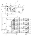
以下、本発明に係る空気調和装置の実施の形態について、図面を参照しながら説明する。図1は、本発明の実施の形態1に係る空気調和装置100を示す回路図である。図1に示すように、空気調和装置100は、熱源機1と、複数の室内機30a~30dと、中継装置20と、制御装置50とを備えている。なお、本実施の形態1では、1台の熱源機1に4台の室内機30a~30dが接続されている場合について例示するが、熱源機1の台数は、1台でもよいし、4台以外の複数でもよい。
以下、本発明に係る空気調和装置の実施の形態について、図面を参照しながら説明する。図1は、本発明の実施の形態1に係る空気調和装置100を示す回路図である。図1に示すように、空気調和装置100は、熱源機1と、複数の室内機30a~30dと、中継装置20と、制御装置50とを備えている。なお、本実施の形態1では、1台の熱源機1に4台の室内機30a~30dが接続されている場合について例示するが、熱源機1の台数は、1台でもよいし、4台以外の複数でもよい。
図1に示すように、空気調和装置100は、熱源機1と、室内機30a~30dと、中継装置20とが、高圧配管4a、低圧配管4b及び冷媒配管5a,5bを介して接続された冷媒回路100Aを備えている。熱源機1は、4台の室内機30a~30dに冷熱又は温熱を供給する機能を有している。4台の室内機30a~30dは、それぞれ互いに並列に接続されており、それぞれ同じ構成となっている。室内機30a~30dは、熱源機1から供給される冷熱又は温熱によって、室内等の空調対象空間を冷房又は暖房する機能を有している。
中継装置20は、熱源機1と室内機30a~30dとの間に介在し、室内機30a~30dからの要求に応じて熱源機1から供給される冷媒の流れを切り替える機能を有している。また、空気調和装置100は、熱源機1に熱源熱媒体を供給する熱媒体回路100Bを有している。
また、空気調和装置100は、各種センサを有している。空気調和装置100は、例えば吐出圧力センサ15と、吸入圧力センサ16と、熱媒体温度センサ17と、第1の負荷温度センサ43と、第2の負荷温度センサ44と、空気温度センサ45と、第1の圧力センサ41と、第2の圧力センサ42とを有している。
ここで、空気調和装置100は、運転モードとして、全冷房運転、全暖房運転、冷房主体運転及び暖房主体運転を有している。全冷房運転は、室内機30a~30dの全てが冷房運転を行うモードである。全暖房運転は、室内機30a~30dの全てが暖房運転を行うモードである。冷房主体運転は、冷暖混在運転のうち、冷房運転の容量が暖房運転の容量よりも大きいモードである。暖房主体運転は、冷暖混在運転のうち、暖房運転の容量が冷房運転の容量よりも大きいモードである。
(熱源機1)
熱源機1は、例えばビル又は家屋等の建物の外等に配置される。なお、熱源機1は、機械室等の建物内の空間に配置されてもよい。熱源機1は、中継装置20を介して4台の室内機30a~30dに冷熱又は温熱を供給する。熱源機1は、圧縮機10、第1の流路切替装置11、熱源側熱交換器12、アキュムレータ13及び熱源側流路調整ユニット14を有している。
熱源機1は、例えばビル又は家屋等の建物の外等に配置される。なお、熱源機1は、機械室等の建物内の空間に配置されてもよい。熱源機1は、中継装置20を介して4台の室内機30a~30dに冷熱又は温熱を供給する。熱源機1は、圧縮機10、第1の流路切替装置11、熱源側熱交換器12、アキュムレータ13及び熱源側流路調整ユニット14を有している。
圧縮機10は、吸入した冷媒を圧縮して高温高圧の状態で吐出する。圧縮機10は、吐出側が第1の流路切替装置11に接続され、吸入側がアキュムレータ13に接続される。圧縮機10は、例えば容量制御可能なインバータ圧縮機等で構成されている。第1の流路切替装置11は、例えば四方弁等からなり、運転モードに応じて冷媒の流れる方向を切り替える。第1の流路切替装置11は、冷房運転時に、圧縮機10の吐出側と熱源側熱交換器12とを接続し、熱源側流路調整ユニット14とアキュムレータ13の吸入側とを接続する。第1の流路切替装置11は、暖房運転時に、圧縮機10の吐出側と熱源側流路調整ユニット14とを接続し、熱源側熱交換器12とアキュムレータ13の吸入側とを接続する。なお、第1の流路切替装置11は、四方弁である場合について例示しているが、二方弁又は三方弁等を組み合わせることによって構成されてもよい。
熱源側熱交換器12は、例えばプレート内を流れる冷媒とプレート内を流れる熱源熱媒体との間で熱交換するプレート型熱交換器からなる。熱源側熱交換器12は、一方が第1の流路切替装置11に接続され、他方が熱源側流路調整ユニット14を介して高圧配管4aに接続されている。熱源側熱交換器12は、冷房運転時に放熱器として作用し、暖房運転時に蒸発器として作用する。アキュムレータ13は、暖房運転時に流れる冷媒と冷房運転時に流れる冷媒との差である余剰冷媒を蓄える。また、アキュムレータ13は、例えば室内機30a~30dの運転台数の変化といった過度的な運転の変化によって生じる余剰冷媒を蓄える。アキュムレータ13は、一方が圧縮機10の吸入側に接続され、他方が第1の流路切替装置11に接続されている。
熱源側流路調整ユニット14は、冷房運転及び暖房運転のいずれの場合にも、熱源機1から中継装置20に流れる冷媒の流れを一定方向にするものであり、第1の逆止弁14a、第2の逆止弁14b、第3の逆止弁14c及び第4の逆止弁14dを有している。第1の逆止弁14aは、第1の流路切替装置11と高圧配管4aとを接続する配管に設けられ、第1の流路切替装置11から高圧配管4aに向かう冷媒の流れを許容する。第2の逆止弁14bは、熱源側熱交換器12と低圧配管4bとを接続する配管に設けられ、低圧配管4bから熱源側熱交換器12に向かう冷媒の流れを許容する。第3の逆止弁14cは、熱源側熱交換器12と高圧配管4aとを接続する配管に設けられ、熱源側熱交換器12から高圧配管4aに向かう冷媒の流れを許容する。第4の逆止弁14dは、第1の流路切替装置11と低圧配管4bとを接続する配管に設けられ、低圧配管4bから第1の流路切替装置11に向かう冷媒の流れを許容する。
また、熱源機1には、吐出圧力センサ15と、吸入圧力センサ16と、熱媒体温度センサ17とが設けられている。吐出圧力センサ15は、圧縮機10と第1の流路切替装置11との間に流れる冷媒の圧力を検出する。吸入圧力センサ16は、第1の流路切替装置11とアキュムレータ13との間に流れる冷媒の圧力を検出する。熱媒体温度センサ17は、熱媒体回路100Bに流れる熱源熱媒体の温度を検出する。なお、吐出圧力センサ15及び吸入圧力センサ16は、熱源機1内のほかの冷媒配管に設けられてもよいし、中継装置20内に設けられてもよい。
(室内機30a~30d)
室内機30a~30dは、例えば居室等の建物の内部の空間である室内空間において、冷房用空気又は暖房用空気を供給することができる位置に配置されている。これにより、室内機30a~30dは、空調対象空間である室内空間に冷房用空気又は暖房用空気を供給する。室内機30a~30dには、有線又は無線によってリモコン(図示せず)が接続されており、利用者がリモコンを操作することによって、リモコンから室内機30a~30dに所定の信号が送信される。各室内機30a~30dは、それぞれ負荷側熱交換器31及び膨張部32を有している。
室内機30a~30dは、例えば居室等の建物の内部の空間である室内空間において、冷房用空気又は暖房用空気を供給することができる位置に配置されている。これにより、室内機30a~30dは、空調対象空間である室内空間に冷房用空気又は暖房用空気を供給する。室内機30a~30dには、有線又は無線によってリモコン(図示せず)が接続されており、利用者がリモコンを操作することによって、リモコンから室内機30a~30dに所定の信号が送信される。各室内機30a~30dは、それぞれ負荷側熱交換器31及び膨張部32を有している。
負荷側熱交換器31は、例えばファン等の送風機(図示せず)から供給される空気といった負荷熱媒体と冷媒との間で熱交換して、室内空間に供給するための冷房用空気又は暖房用空気を生成する。負荷側熱交換器31は、冷媒配管5aを介して、中継装置20にそれぞれ接続されている。膨張部32は、例えば開度が変更自在の電子式膨張弁からなり、冷媒を減圧して膨張させる。膨張部32は、冷房運転時に冷媒を減圧して膨張させて負荷側熱交換器31に供給する。膨張部32は、暖房運転時に冷媒を減圧して膨張させて中継装置20に供給する。
また、室内機30a~30dには、それぞれ、第1の負荷温度センサ43と、第2の負荷温度センサ44と、空気温度センサ45とが設けられている。第1の負荷温度センサ43は、負荷側熱交換器31と膨張部32との間に設けられ、負荷側熱交換器31と膨張部32との間に流れる冷媒の温度を検出する。第2の負荷温度センサ44は、負荷側熱交換器31と中継装置20との間に設けられ、負荷側熱交換器31と中継装置20との間に流れる冷媒の温度を検出する。空気温度センサ45は、負荷熱媒体である室内空気の温度を検出する。
(中継装置20)
中継装置20は、熱源機1及び複数の室内機30a~30dとは別の筐体からなり、室外空間及び室内空間とは別の位置に設置可能である。中継装置20は、気液分離器21、第1の絞り装置22、第2の絞り装置23及び第2の流路切替装置24a,24b,24c,24dを有している。中継装置20は、高圧配管4a及び低圧配管4bを介して熱源機1に接続され、冷媒配管5a,5bを介して各室内機30a~30dに接続されている。中継装置20は、熱源機1から供給される冷熱又は温熱を各室内機30a~30dに分配する。
中継装置20は、熱源機1及び複数の室内機30a~30dとは別の筐体からなり、室外空間及び室内空間とは別の位置に設置可能である。中継装置20は、気液分離器21、第1の絞り装置22、第2の絞り装置23及び第2の流路切替装置24a,24b,24c,24dを有している。中継装置20は、高圧配管4a及び低圧配管4bを介して熱源機1に接続され、冷媒配管5a,5bを介して各室内機30a~30dに接続されている。中継装置20は、熱源機1から供給される冷熱又は温熱を各室内機30a~30dに分配する。
気液分離器21は、熱源機1から供給される高圧の気液二相冷媒を、液冷媒とガス冷媒とに分離する。気液分離器21は、中継装置20の入口に設置され、高圧配管4aを介して熱源機1に接続されている。気液分離器21は、上部にガス管21aが接続され、下部に液管21bが接続されている。気液分離器21によって分離された冷媒のうち液冷媒は、液管21bから第2の流路切替装置24a,24b,24c,24dを介して室内機30a~30dに流れる。これにより、室内機30a~30dに冷熱が供給される。気液分離器21によって分離された冷媒のうちガス冷媒は、ガス管21aから第2の流路切替装置24a,24b,24c,24dを介して室内機30a~30dに流れる。これにより、室内機30a~30dに温熱が供給される。
第1の絞り装置22は、減圧弁及び開閉弁の機能を有し、例えば開度が可変の電子式膨張弁からなる。第1の絞り装置22は、液管21bに設けられている。第1の絞り装置22は、液冷媒を目標圧力まで減圧させるとともに、液冷媒の流路を開閉する。第2の絞り装置23は、減圧弁及び開閉弁の機能を有し、例えば開度が可変の電子式膨張弁からなる。第2の絞り装置23は、低圧配管4bに接続される中継装置20の出口側の低圧配管4bと、第1の絞り装置22の出口側に接続される配管との間に設けられている。第2の絞り装置23は、全暖房運転モードにおいて、冷媒の流路を開いて冷媒をバイパスさせ、暖房主体運転モードにおいて、負荷側の負荷に応じて開度を調整し、バイパス流量を調整する。
第2の流路切替装置24a,24b,24c,24dは、複数の室内機30a~30dの運転モードに応じて流路を切り替えるものであり、室内機30a~30dの設置台数と同じ個数だけ設置される。第2の流路切替装置24a,24b,24c,24dは、第1の開閉装置25a及び第2の開閉装置25bと、第5の逆止弁26a及び第6の逆止弁26bとを有している。第1の開閉装置25a及び第2の開閉装置25bは、ガス管21a、低圧配管4b及び熱源側熱交換器12に接続される冷媒配管5aに接続されている。第5の逆止弁26a及び第6の逆止弁26bは、液管21b及び膨張部32に接続される冷媒配管5bに接続されている。なお、本実施の形態1では、第2の流路切替装置24a,24b,24c,24dが第5の逆止弁26a、第6の逆止弁26b、第1の開閉装置25a及び第2の開閉装置25bを有している場合について例示しているが、例えば四方弁等で構成されてもよい。
第1の開閉装置25aは、例えば電磁弁等からなり、ガス管21aと冷媒配管5aとの間に設けられている。第1の開閉装置25aは、室内機30a~30dの暖房運転時に開放され、室内機30a~30dの冷房運転時に閉止される。第2の開閉装置25bは、例えば電磁弁等からなり、冷媒配管5bと低圧配管4bとの間に設けられている。第2の開閉装置25bは、室内機30a~30dの冷房運転時に開放され、室内機30a~30dの暖房運転時に閉止される。第1の開閉装置25aと第2の開閉装置25bとは、互いに並列に接続されている。
第5の逆止弁26aは、一方が冷媒配管5bに接続され、他方が第1の絞り装置22及び第2の絞り装置23に接続されている。第5の逆止弁26aは、第1の絞り装置22側から室内機30a~30dに流れる冷媒の流れを許容する。これにより、室内機30a~30dの冷房運転時に、冷媒が第5の逆止弁26aを通って室内機30a~30dに流入する。第6の逆止弁26bは、一方が冷媒配管5bに接続され、他方が第1の絞り装置22及び第2の絞り装置23に接続されている。第6の逆止弁26bは、冷媒配管5b側から第2の絞り装置23に流れる冷媒の流れを許容する。これにより、室内機30a~30dの暖房運転時に、冷媒が第6の逆止弁26bを通って第2の絞り装置23に流入する。
また、中継装置20には、第1の圧力センサ41と第2の圧力センサ42とが設けられている。第1の圧力センサ41は、気液分離器21と第1の絞り装置22との間に流れる冷媒の圧力を検出する。第2の圧力センサ42は、第1の絞り装置22を通過した冷媒の圧力を検出する。なお、第1の圧力センサ41、第1の負荷温度センサ43及び第2の負荷温度センサ44は、負荷側熱交換器31を流れる冷媒の温度を検出する冷媒温度センサとして機能する。
(冷媒)
空気調和装置100に用いられる冷媒は、例えばR410A、R407C又はR404A等のHFC冷媒でもよいし、R22又はR134a等のHCFC冷媒でもよいし、炭化水素又はヘリウム等の自然冷媒でもよい。
空気調和装置100に用いられる冷媒は、例えばR410A、R407C又はR404A等のHFC冷媒でもよいし、R22又はR134a等のHCFC冷媒でもよいし、炭化水素又はヘリウム等の自然冷媒でもよい。
(熱媒体回路100B)
熱媒体回路100Bは、ポンプ61、流量調整弁60及び熱源側熱交換器12が熱媒体配管62により接続され、熱源熱媒体が流れる。ポンプ61は、熱源側熱媒体を熱源側熱交換器12に搬送する。ポンプ61は、通常、予め設定された設定出力で駆動している。流量調整弁60は、開度調整可能であり、熱媒体回路100Bを循環する熱源熱媒体の流量を調整する。なお、流量調整弁60は、部品としての最小開度が全閉であり、流入する熱源熱媒体を全て遮断する。なお、流量調整弁60は、部品として最小開度が全閉ではなく、若干開いているものであってもよい。この場合、二方弁等が併用されることによって、全閉と同じように熱源熱媒体の流れを遮断することができる。また、流量調整弁60は、部品としての最大開度が全開であり、流入する熱源熱媒体を全てそのまま流出させる。
熱媒体回路100Bは、ポンプ61、流量調整弁60及び熱源側熱交換器12が熱媒体配管62により接続され、熱源熱媒体が流れる。ポンプ61は、熱源側熱媒体を熱源側熱交換器12に搬送する。ポンプ61は、通常、予め設定された設定出力で駆動している。流量調整弁60は、開度調整可能であり、熱媒体回路100Bを循環する熱源熱媒体の流量を調整する。なお、流量調整弁60は、部品としての最小開度が全閉であり、流入する熱源熱媒体を全て遮断する。なお、流量調整弁60は、部品として最小開度が全閉ではなく、若干開いているものであってもよい。この場合、二方弁等が併用されることによって、全閉と同じように熱源熱媒体の流れを遮断することができる。また、流量調整弁60は、部品としての最大開度が全開であり、流入する熱源熱媒体を全てそのまま流出させる。
熱源側熱交換器12は、前述の如く、例えばプレート内を流れる冷媒とプレート内を流れる熱源熱媒体との間で熱交換するプレート型熱交換器からなる。熱源側熱交換器12は、一方が流量調整弁60に接続され、他方がポンプ61の吸入側に接続される。熱源側熱交換器12は、冷房運転時に放熱器として作用し、これにより、熱源熱媒体が加熱される。熱源側熱交換器12は、暖房運転時に蒸発器として作用し、これにより、熱源熱媒体が冷却される。なお、熱源側熱交換器12には、熱源熱媒体を流すことができる流量が予め決められている。これを、本実施の形態1では、熱源機1の流量能力の範囲と呼称する場合がある。
熱媒体回路100Bには、熱源機1に設けられた熱媒体温度センサ17及び流量センサ63が設けられている。熱媒体温度センサ17は、熱媒体回路100Bに流れる熱源熱媒体の温度を検出する。流量センサ63は、熱媒体配管62に設けられ、熱媒体回路100Bに流れる熱源熱媒体の流量を検出する。本実施の形態1では、流量センサ63は、熱源熱媒体の流量を直接計測する流量計である場合について例示しているが、流量センサ63は、2個の圧力計としてもよい。この場合、圧力計は、熱源側熱交換器12の入口側及び出口側に流れる熱源熱媒体の圧力を検出する。そして、制御装置50は、2個の圧力計によって計測された圧力の差圧に基づいて熱源熱媒体の流量を推定する。なお、本実施の形態1では、1台の熱源機1と1台のポンプ61とが接続されているが、これに限らず、1台のポンプ61に複数台の熱源機1が接続されてもよい。
(熱媒体)
熱媒体回路100Bに用いられる熱源熱媒体は、例えば水であるが、ブラインとしてもよい。熱源熱媒体が水である場合、熱源側熱交換器12において、冷媒と水とで熱交換して、冷熱又は温熱を室内機30a~30dに供給する。即ち、本実施の形態1の空気調和装置100は、水冷式の空気調和装置100である。
熱媒体回路100Bに用いられる熱源熱媒体は、例えば水であるが、ブラインとしてもよい。熱源熱媒体が水である場合、熱源側熱交換器12において、冷媒と水とで熱交換して、冷熱又は温熱を室内機30a~30dに供給する。即ち、本実施の形態1の空気調和装置100は、水冷式の空気調和装置100である。
(制御装置50)
図2は、本発明の実施の形態1に係る空気調和装置100を示すハードウエア構成図である。図2に示すように、制御装置50は、マイコン等で構成されており、各センサによって検出された検出情報及びリモコンから送信された指示信号に基づいて、空気調和装置100の動作を制御する。なお、本実施の形態1では、制御装置50は、熱源機1に設けられている場合について例示しているが、制御装置50は、室内機30a~30dに設けられていてもよい。また、制御装置50は、熱源機1及び室内機30a~30dとは別の筐体として設けられていてもよい。
図2は、本発明の実施の形態1に係る空気調和装置100を示すハードウエア構成図である。図2に示すように、制御装置50は、マイコン等で構成されており、各センサによって検出された検出情報及びリモコンから送信された指示信号に基づいて、空気調和装置100の動作を制御する。なお、本実施の形態1では、制御装置50は、熱源機1に設けられている場合について例示しているが、制御装置50は、室内機30a~30dに設けられていてもよい。また、制御装置50は、熱源機1及び室内機30a~30dとは別の筐体として設けられていてもよい。
制御装置50は、第1の圧力センサ41によって検出された圧力と、第2の圧力センサ42によって検出された圧力との差が目標圧力差となるように、第1の絞り装置22の開度を制御する。目標圧力差は、例えば0.3MPaである。制御装置50は、冷房運転時に、第1の負荷温度センサ43によって検出された温度と第2の負荷温度センサ44によって検出された温度との差として得られるスーパーヒート(過熱度)が一定となるように、膨張部32の開度を制御する。制御装置50は、暖房運転時に、第1の圧力センサ41によって検出された圧力を飽和温度に変換した値と、第1の負荷温度センサ43によって検出された温度との差として得られるサブクール(過冷却度)が一定となるように、膨張部32の開度を制御する。
また、制御装置50は、吐出圧力センサ15によって検出された圧力が目標圧力を下回らないように圧縮機10の圧縮量を制御する。制御装置50は、吸入圧力センサ16によって検出された圧力が目標圧力の範囲内に収まるように、圧縮機10の圧縮量を制御する。制御装置50は、熱媒体温度センサ17によって検出された温度が目標温度の範囲外となる場合、空気調和装置100の運転を停止させて、機器の損傷を抑制する。
なお、空気調和装置100は、報知手段7を備えていてもよい。報知手段7は、例えば表示装置又はスピーカ等である。制御装置50は、各センサによって検出された検出情報及びリモコンから送信された指示信号に基づいて、表示装置に検出情報又は指示内容を表示する。また、制御装置50は、各センサによって検出された検出情報及びリモコンから送信された指示信号に基づいて、スピーカに所定の音声を出力させる。また、制御装置50は、リモコン等からの指示を受けた各室内機30a~30dからの情報を取得して、各室内機30a~30dが冷房運転又は暖房運転をするように制御する。即ち、空気調和装置100は、室内の全てが同一運転を行うことができると共に、それぞれの室内機30a~30dが異なる運転を行うこともできる。
制御装置50は、熱媒体回路100Bに流れる熱源熱媒体の流量が、熱源機1の流量能力の範囲内に収まるように、空調負荷に応じた流量調整弁60の開度を制御している。例えば、制御装置50は、空調負荷が大きいときに、流量調整弁60の開度を増加させて、熱媒体の流量を増加させる。また、制御装置50は、空調負荷が小さいときに、流量調整弁60の開度を減少させて、熱源熱媒体の流量を減少させる。これにより、必要なときに必要な分だけ熱源熱媒体を使用することができる。
図3は、本発明の実施の形態1に係る空気調和装置100の制御装置50を示すブロック図である。図3に示すように、制御装置50は、記憶手段51と、開度設定手段52とを有している。記憶手段51は、例えばメモリ等で構成されており、熱媒体回路100Bに流れる熱源熱媒体の規定最大流量Fmax及び規定最小流量Fminを記憶する。空気調和装置100において、熱源側熱交換器12に流すことができる熱源熱媒体の流量は予め定められているため、熱媒体回路100Bに流れる熱源熱媒体の流量には、最大から最小までの範囲が設けられている。
規定最大流量Fmaxとは、熱源側熱交換器12に流すことができる熱源熱媒体の最大流量をいう。また、規定最小流量Fminとは、熱源側熱交換器12に熱源熱媒体が流れる上で、最低限必要な熱源熱媒体の流量をいう。なお、規定最大流量Fmax及び規定最小流量Fminは、制御装置50の切替スイッチ(図示せず)又は、制御装置50に対し外部入力によって設定される。外部入力とは、例えば端末等を用いて記憶手段51に規定最大流量Fmax及び規定最小流量Fminを入力することをいう。
開度設定手段52は、流量センサ63によって検出された検出流量と、記憶手段51に記憶された規定最大流量Fmaxと、記憶手段51に記憶された規定最小流量Fminとに基づいて、流量調整弁60の最大開度及び最小開度を設定するものである。最大開度とは、部品としての最大開度とは異なり、熱源機1の流量能力の範囲の上限値である規定最大流量Fmaxに対応する開度をいう。最小開度とは、部品としての最小開度とは異なり、熱源機1の流量能力の範囲の下限値である規定最小流量Fminに対応する開度をいう。ここで、開度設定手段52は、最大設定手段52aと、最小設定手段52bとを有している。
図4は、本発明の実施の形態1における流量調整弁60の開度と熱源熱媒体の流量との関係を示すグラフである。図4において、横軸は流量調整弁60の開度Lであり、縦軸は熱源熱媒体の流量Fである。最大設定手段52aは、ポンプ61が設定出力で駆動している際、流量センサ63によって検出された流量が規定最大流量Fmaxを上回る場合、流量調整弁60の開度を調整開度ΔLだけ減少させる。一方、最大設定手段52aは、ポンプ61が設定出力で駆動している際、流量センサ63によって検出された流量が規定最大流量Fmaxから許容流量ΔQwを減算した値を下回る場合、流量調整弁60の開度を調整開度ΔLだけ増加させる。これにより、最大設定手段52aは、最大開度を設定する。ここで、許容流量ΔQwは、熱源機1の流量能力の範囲の上限値である規定最大流量Fmax自体の範囲を決定するパラメータである。また、調整開度ΔLは、流量調整弁60の開度を調整する際の調整幅である。なお、許容流量ΔQwに対応する開度は、調整開度ΔLより大きい。これにより、流量調整弁60の開度を調整する際に、調整範囲を超えて調整してしまうことを抑制することができる。
図4に示すように、最大設定手段52aは、流量調整弁60の開度を、予め設定されている所定の初期開度L0に設定する。そして、最大設定手段52aは、流量センサ63によって検出された検出流量が規定最大流量Fmaxを上回る場合、流量調整弁60の初期開度L0を調整開度ΔLだけ減少させる。そして、所定の時間が経過して、流量センサ63によって検出された検出流量が規定最大流量Fmaxを下回るまで、開度Lを調整開度ΔLだけ毎回繰り返し減少させる。
一方、最大設定手段52aは、流量センサ63によって検出された検出流量が規定最大流量Fmaxから許容流量ΔQwを減算した値を下回る場合、流量調整弁60の開度Lを調整開度ΔLだけ増加させる。そして、所定の時間が経過して、流量センサ63によって検出された検出流量が規定最大流量Fmaxから許容流量ΔQwを減算した値を上回るまで、開度Lを調整開度ΔLだけ毎回繰り返し増加させる。なお、調整開度ΔLは、規定最大流量Fmaxを下回るまでの開度と、規定最大流量Fmaxから許容流量ΔQwを減算した値を上回るまでの開度とで、変更されてもよい。
最大設定手段52aは、流量センサ63によって検出された検出流量が規定最大流量Fmax以下且つ規定最大流量Fmaxから許容流量ΔQwを減算した値以上の条件を満足すると、そのときの設定開度Lを最大開度Lmaxとして設定する。なお、最大開度Lmaxは、部品としての最大開度Lallよりも開度が小さい。
最小設定手段52bは、ポンプ61が設定出力で駆動している際、流量センサ63によって検出された検出流量が規定最小流量Fminを下回る場合、流量調整弁60の開度を調整開度ΔLだけ増加させる。一方、最小設定手段52bは、ポンプ61が設定出力で駆動している際、流量センサ63によって検出された検出流量が規定最小流量Fminを上回る場合、流量調整弁60の開度を調整開度ΔLだけ減少させる。これにより、最小設定手段52bは、最小開度を設定する。
最小設定手段52bは、流量センサ63によって検出された検出流量が規定最小流量Fminを下回る場合、流量調整弁60の設定開度Lを調整開度ΔLだけ増加させる。そして、所定の時間が経過して、流量センサ63によって検出された流量が規定最小流量Fminを上回るまで、開度Lを調整開度ΔLだけ毎回繰り返し増加させる。一方、最小設定手段52bは、流量センサ63によって検出された検出流量が規定最小流量Fminに許容流量ΔQwを加算した値を上回る場合、流量調整弁60の開度Lを調整開度ΔLだけ減少させる。そして、所定の時間が経過して、流量センサ63によって検出された検出流量が規定最小流量Fminに許容流量ΔQwを加算した値を下回るまで、開度Lを調整開度ΔLだけ毎回繰り返し減少させる。なお、調整開度ΔLは、規定最小流量Fminを上回るまでの開度と、規定最小流量Fminに許容流量ΔQwを加算した値を下回るまでの開度とで、変更されてもよい。最小設定手段52bは、流量センサ63によって検出された検出流量が規定最小流量Fmin以上且つ規定最小流量Fminに許容流量ΔQwを加算した値以下の条件を満足すると、そのときの設定開度Lを最小開度Lminとして設定する。
空調負荷に応じて変化する流量調整弁60の開度は、設定された最大開度と最小開度との間の範囲内で調整されるため、熱媒体回路100Bを循環する熱源熱媒体の流量は、熱源機1の流量能力の範囲内に収まる。
以上のように、開度設定手段52は、記憶手段51に記憶された規定最大流量Fmax及び規定最小流量Fminに基づいて流量調整弁60の最大開度及び最小開度を設定している。このため、圧縮機10の動作の有無にかかわらず、流量調整弁60の最大開度及び最小開度を設定することができる。従って、本実施の形態1の開度設定手段52は、圧縮機10の非運転時に、流量調整弁60の最大開度及び最小開度を設定することができる。
次に、空気調和装置100の各運転モードにおける動作について説明する。前述の如く、空気調和装置100は、運転モードとして、全冷房運転、全暖房運転、冷房主体運転及び暖房主体運転を有している。なお、以下の説明では、室内機30a,30bが運転し、室内機30c,30dについては空調負荷が無く冷媒を流す必要がない場合について例示する。従って、室内機30c,30dに設けられたそれぞれの膨張部32は、閉止される。なお、室内機30c,30dにおいて空調負荷の発生が生じた場合、それぞれの膨張部32が開放されて、冷媒が循環するようにしてもよい。
(全冷房運転)
図5は、本発明の実施の形態1に係る空気調和装置100の全冷房運転時の冷媒の流れを示す回路図である。先ず、全冷房運転について説明する。空気調和装置100において、室内機30a,30bが冷房運転を行い、室内機30c,30dは停止している。第1の流路切替装置11は、圧縮機10から吐出された冷媒が熱源側熱交換器12に流れるように切り替えられる。図5に示すように、低温且つ低圧の冷媒が圧縮機10に吸入され、圧縮機10から吐出された高温且つ高圧のガス冷媒は、第1の流路切替装置11を通り、放熱器として作用する熱源側熱交換器12に流入する。
図5は、本発明の実施の形態1に係る空気調和装置100の全冷房運転時の冷媒の流れを示す回路図である。先ず、全冷房運転について説明する。空気調和装置100において、室内機30a,30bが冷房運転を行い、室内機30c,30dは停止している。第1の流路切替装置11は、圧縮機10から吐出された冷媒が熱源側熱交換器12に流れるように切り替えられる。図5に示すように、低温且つ低圧の冷媒が圧縮機10に吸入され、圧縮機10から吐出された高温且つ高圧のガス冷媒は、第1の流路切替装置11を通り、放熱器として作用する熱源側熱交換器12に流入する。
熱源側熱交換器12に流入した冷媒は、熱源側熱交換器12において熱源熱媒体に放熱して液化される。液化された高圧の液冷媒は、第3の逆止弁14cを通って熱源機1から流出し、高圧配管4aを通って中継装置20に流入する。中継装置20に流入した高圧の液冷媒は、気液分離器21、第1の絞り装置22、第2の流路切替装置24a,24bの第5の逆止弁26a及び冷媒配管5bを経由して各室内機30a,30bに流入する。
そして、室内機30a,30bに流入した冷媒は、負荷側熱交換器31の出口側のスーパーヒートが一定となるように制御された膨張部32によって、膨張され、低温且つ低圧の気液二相の冷媒となる。気液二相の冷媒は、蒸発器として作用する負荷側熱交換器31に流入し、負荷熱媒体である室内空気から吸熱することによって、室内空気を冷却しつつ、低温且つ低圧のガス冷媒となる。その際、室内が冷房される。室内機30a,30bから流出したガス冷媒は、冷媒配管5a及び第2の流路切替装置24a,24bの第2の開閉装置25bを通って、中継装置20から流出する。中継装置20から流出した冷媒は、低圧配管4bを通って、再び熱源機1に流入する。熱源機1に流入した冷媒は、第4の逆止弁14dを通って第1の流路切替装置11及びアキュムレータ13を経由して、圧縮機10に再度吸入される。
次に、熱媒体回路100Bの熱源熱媒体の流れについて説明する。ポンプ61に吸入された熱源熱媒体は、ポンプ61から吐出され、流量調整弁60を通って熱源側熱交換器12に流入する。熱源側熱交換器12に流入した熱源熱媒体は、冷媒と熱交換されて加熱される。加熱された熱源熱媒体は、再びポンプ61に吸入される。
(全暖房運転)
図6は、本発明の実施の形態1に係る空気調和装置100の全暖房運転時の冷媒の流れを示す回路図である。次に、全暖房運転について説明する。空気調和装置100において、室内機30a,30bが暖房運転を行い、室内機30c,30dは停止している。第1の流路切替装置11は、圧縮機10から吐出された冷媒が熱源側熱交換器12を経由せずに中継装置20に流れるように切り替えられる。図6に示すように、低温且つ低圧の冷媒が圧縮機10に吸入され、圧縮機10から吐出された高温且つ高圧のガス冷媒は、第1の流路切替装置11及び第1の逆止弁14aを通り、高圧配管4aを通って中継装置20に流入する。中継装置20に流入した高温且つ高圧のガス冷媒は、気液分離器21、第2の流路切替装置24a,24bの第1の開閉装置25a及び冷媒配管5aを経由して各室内機30a,30bに流入する。
図6は、本発明の実施の形態1に係る空気調和装置100の全暖房運転時の冷媒の流れを示す回路図である。次に、全暖房運転について説明する。空気調和装置100において、室内機30a,30bが暖房運転を行い、室内機30c,30dは停止している。第1の流路切替装置11は、圧縮機10から吐出された冷媒が熱源側熱交換器12を経由せずに中継装置20に流れるように切り替えられる。図6に示すように、低温且つ低圧の冷媒が圧縮機10に吸入され、圧縮機10から吐出された高温且つ高圧のガス冷媒は、第1の流路切替装置11及び第1の逆止弁14aを通り、高圧配管4aを通って中継装置20に流入する。中継装置20に流入した高温且つ高圧のガス冷媒は、気液分離器21、第2の流路切替装置24a,24bの第1の開閉装置25a及び冷媒配管5aを経由して各室内機30a,30bに流入する。
そして、室内機30a,30bに流入した高温且つ高圧のガス冷媒は、凝縮器として作用する負荷側熱交換器31に流入し、負荷熱媒体である室内空気に放熱することによって、室内空気を加熱しつつ、液冷媒となる。その際、室内が暖房される。負荷側熱交換器31から流出した液冷媒は、負荷側熱交換器31の出口側のサブクールが一定となるように制御された膨張部32によって、膨張され、低温且つ低圧の気液二相の冷媒となる。その後、冷媒は、冷媒配管5b、第6の逆止弁26b及び第2の絞り装置23を通って、中継装置20から流出する。
中継装置20から流出した冷媒は、低圧配管4bを通って、再び熱源機1に流入する。熱源機1に流入した冷媒は、第2の逆止弁14bを通って、蒸発器として作用する熱源側熱交換器12に流入する。熱源側熱交換器12に流入した冷媒は、熱源側熱交換器12において熱源熱媒体から吸熱して、低温且つ低圧のガス冷媒となる。熱源側熱交換器12から流出した低温且つ低圧のガス冷媒は、第1の流路切替装置11及びアキュムレータ13を経由して、圧縮機10に再度吸入される。
次に、熱媒体回路100Bの熱源熱媒体の流れについて説明する。ポンプ61に吸入され熱源熱媒体は、ポンプ61から吐出され、流量調整弁60を通って熱源側熱交換器12に流入する。熱源側熱交換器12に流入した熱源熱媒体は、冷媒と熱交換されて冷却される。冷却された熱源熱媒体は、再びポンプ61に吸入される。
(冷房主体運転)
図7は、本発明の実施の形態1に係る空気調和装置100の冷房主体運転時の冷媒の流れを示す回路図である。次に、冷房主体運転について説明する。空気調和装置100において、室内機30aが冷房運転を行い、室内機30bが暖房運転を行い、室内機30c,30dは停止している。第1の流路切替装置11は、圧縮機10から吐出された冷媒が熱源側熱交換器12に流れるように切り替えられる。図7に示すように、低温且つ低圧の冷媒が圧縮機10に吸入され、圧縮機10から吐出された高温且つ高圧のガス冷媒は、第1の流路切替装置11を通り、放熱器として作用する熱源側熱交換器12に流入する。熱源側熱交換器12に流入した冷媒は、熱源側熱交換器12において熱源熱媒体に放熱して気液二相の冷媒となる。気液二相の冷媒は、第3の逆止弁14cを通って熱源機1から流出し、高圧配管4aを通って中継装置20に流入する。中継装置20に流入した気液二相の冷媒は、気液分離器21において、高圧のガス冷媒と高圧の液冷媒とに分離される。
図7は、本発明の実施の形態1に係る空気調和装置100の冷房主体運転時の冷媒の流れを示す回路図である。次に、冷房主体運転について説明する。空気調和装置100において、室内機30aが冷房運転を行い、室内機30bが暖房運転を行い、室内機30c,30dは停止している。第1の流路切替装置11は、圧縮機10から吐出された冷媒が熱源側熱交換器12に流れるように切り替えられる。図7に示すように、低温且つ低圧の冷媒が圧縮機10に吸入され、圧縮機10から吐出された高温且つ高圧のガス冷媒は、第1の流路切替装置11を通り、放熱器として作用する熱源側熱交換器12に流入する。熱源側熱交換器12に流入した冷媒は、熱源側熱交換器12において熱源熱媒体に放熱して気液二相の冷媒となる。気液二相の冷媒は、第3の逆止弁14cを通って熱源機1から流出し、高圧配管4aを通って中継装置20に流入する。中継装置20に流入した気液二相の冷媒は、気液分離器21において、高圧のガス冷媒と高圧の液冷媒とに分離される。
気液分離器21において分離された高圧のガス冷媒は、ガス管21a、第2の流路切替装置24bの第1の開閉装置25a及び冷媒配管5aを経由して、室内機30bに流入する。室内機30bに流入した高温のガス冷媒は、凝縮器として作用する負荷側熱交換器31に流入し、負荷熱媒体である室内空気に放熱することによって、室内空気を加熱しつつ、液冷媒となる。その際、室内が暖房される。負荷側熱交換器31から流出した液冷媒は、負荷側熱交換器31の出口側のサブクールが一定となるように制御された膨張部32によって、膨張される。その後、冷媒は、冷媒配管5b及び第6の逆止弁26bを通って、第1の絞り装置22の出口側に流れる。
一方、気液分離器21において分離された高圧の液冷媒は、液管21bを通って第1の絞り装置22において中間圧にまで膨張され、室内機30bから流出した冷媒と合流する。なお、中間圧とは、例えば高圧から0.3MPa程度減算した値である。合流した中間圧の液冷媒は、第5の逆止弁26a及び冷媒配管5bを経由して室内機30aに流入する。そして、室内機30aに流入した冷媒は、負荷側熱交換器31の出口側のスーパーヒートが一定となるように制御された膨張部32によって、膨張され、低温且つ低圧の気液二相の冷媒となる。
気液二相の冷媒は、蒸発器として作用する負荷側熱交換器31に流入し、負荷熱媒体である室内空気から吸熱することによって、室内空気を冷却しつつ、低温且つ低圧のガス冷媒となる。その際、室内が冷房される。室内機30aから流出したガス冷媒は、冷媒配管5a及び第2の流路切替装置24aの第2の開閉装置25bを通って、中継装置20から流出する。中継装置20から流出した冷媒は、低圧配管4bを通って、再び熱源機1に流入する。熱源機1に流入した冷媒は、第4の逆止弁14dを通って第1の流路切替装置11及びアキュムレータ13を経由して、圧縮機10に再度吸入される。
次に、熱媒体回路100Bの熱源熱媒体の流れについて説明する。ポンプ61に吸入された熱源熱媒体は、ポンプ61から吐出され、流量調整弁60を通って熱源側熱交換器12に流入する。熱源側熱交換器12に流入した熱源熱媒体は、冷媒と熱交換されて加熱される。加熱された熱源熱媒体は、再びポンプ61に吸入される。
(暖房主体運転)
図8は、本発明の実施の形態1に係る空気調和装置100の暖房主体運転時の冷媒の流れを示す回路図である。次に、暖房主体運転について説明する。空気調和装置100において、室内機30aが冷房運転を行い、室内機30bが暖房運転を行い、室内機30c,30dは停止している。第1の流路切替装置11は、圧縮機10から吐出された冷媒が熱源側熱交換器12を経由せずに中継装置20に流れるように切り替えられる。図8に示すように、低温且つ低圧の冷媒が圧縮機10に吸入され、圧縮機10から吐出された高温且つ高圧のガス冷媒は、第1の流路切替装置11及び第1の逆止弁14aを通り、高圧配管4aを通って中継装置20に流入する。中継装置20に流入した高温且つ高圧のガス冷媒は、気液分離器21、ガス管21a、第2の流路切替装置24bの第1の開閉装置25a及び冷媒配管5aを経由して室内機30bに流入する。
図8は、本発明の実施の形態1に係る空気調和装置100の暖房主体運転時の冷媒の流れを示す回路図である。次に、暖房主体運転について説明する。空気調和装置100において、室内機30aが冷房運転を行い、室内機30bが暖房運転を行い、室内機30c,30dは停止している。第1の流路切替装置11は、圧縮機10から吐出された冷媒が熱源側熱交換器12を経由せずに中継装置20に流れるように切り替えられる。図8に示すように、低温且つ低圧の冷媒が圧縮機10に吸入され、圧縮機10から吐出された高温且つ高圧のガス冷媒は、第1の流路切替装置11及び第1の逆止弁14aを通り、高圧配管4aを通って中継装置20に流入する。中継装置20に流入した高温且つ高圧のガス冷媒は、気液分離器21、ガス管21a、第2の流路切替装置24bの第1の開閉装置25a及び冷媒配管5aを経由して室内機30bに流入する。
そして、室内機30bに流入した高温且つ高圧のガス冷媒は、凝縮器として作用する負荷側熱交換器31に流入し、負荷熱媒体である室内空気に放熱することによって、室内空気を加熱しつつ、液冷媒となる。その際、室内が暖房される。負荷側熱交換器31から流出した液冷媒は、負荷側熱交換器31の出口側のサブクールが一定となるように制御された膨張部32によって、膨張され、低温且つ低圧の気液二相の冷媒となる。その後、冷媒は、冷媒配管5b及び第6の逆止弁26bを経由した後、2つのルートに分岐する。一つ目のルートは、第2の流路切替装置24aの第5の逆止弁26aに流入するルートであり、二つ目のルートは、第2の絞り装置23に流入するバイパスとして使用されるルートである。
第5の逆止弁26aを通過した冷媒は、冷媒配管5bを経由して、室内機30aに流入する。そして、室内機30aに流入した冷媒は、負荷側熱交換器31の出口側のスーパーヒートが一定となるように制御された膨張部32によって、膨張され、低温且つ低圧の気液二相の冷媒となる。気液二相の冷媒は、蒸発器として作用する負荷側熱交換器31に流入し、負荷熱媒体である室内空気から吸熱することによって、室内空気を冷却しつつ、低温且つ低圧のガス冷媒となる。その際、室内が冷房される。
室内機30aから流出したガス冷媒は、冷媒配管5a及び第2の流路切替装置24aの第2の開閉装置25bを通って、第2の絞り装置23を通った冷媒と合流して、中継装置20から流出する。中継装置20から流出した冷媒は、低圧配管4bを通って、再び熱源機1に流入する。熱源機1に流入した冷媒は、第2の逆止弁14bを通って、蒸発器として作用する熱源側熱交換器12に流入する。熱源側熱交換器12に流入した冷媒は、熱源側熱交換器12において熱源熱媒体から吸熱して、低温且つ低圧のガス冷媒となる。熱源側熱交換器12から流出した低温且つ低圧のガス冷媒は、第1の流路切替装置11及びアキュムレータ13を経由して、圧縮機10に再度吸入される。
次に、熱媒体回路100Bの熱源熱媒体の流れについて説明する。ポンプ61に吸入された熱源熱媒体は、ポンプ61から吐出され、流量調整弁60を通って熱源側熱交換器12に流入する。熱源側熱交換器12に流入した熱源熱媒体は、冷媒と熱交換されて冷却される。冷却された熱源熱媒体は、再びポンプ61に吸入される。
図9は、本発明の実施の形態1に係る空気調和装置100の動作を示すフローチャートである。次に、制御装置50による流量調整弁60の制御について説明する。先ず、最大設定手段52aの動作について説明する。図9に示すように、先ず、制御装置50によって、流量調整弁60の開度が初期開度L0となるように制御される(ステップST1)。次に、流量センサ63によって熱媒体回路100Bに流れる熱源熱媒体の流量が検出される(ステップST2)。
そして、検出された検出流量Fが、記憶手段51に記憶された規定最大流量Fmaxより大きいかが判定される(ステップST3)。検出流量Fが規定最大流量Fmaxより大きい場合(ステップST3のYES)、最大設定手段52aは、流量調整弁60の開度Lを調整開度ΔL1だけ減少させる(ステップST4)。そして、ステップST2に戻って、最大設定手段52aは、検出流量Fが規定最大流量Fmaxを下回るまで、開度Lを調整開度ΔL1だけ毎回繰り返し減少させる。
検出流量Fが規定最大流量Fmax以下の場合(ステップST3のNO)、検出流量Fが規定最大流量Fmaxから許容流量ΔQwを減算した値より小さいかが判定される(ステップST5)。検出流量Fが規定最大流量Fmaxから許容流量ΔQwを減算した値より小さい場合(ステップST5のYES)、最大設定手段52aは、流量調整弁60の開度Lを調整開度ΔL2だけ増加させる(ステップST6)。そして、ステップST2に戻って、最大設定手段52aは、検出流量Fが規定最大流量Fmaxから許容流量ΔQwを減算した値を上回るまで、開度Lを調整開度ΔL2だけ毎回繰り返し増加させる。
検出流量Fが規定最大流量Fmaxから許容流量ΔQwを減算した値より大きい場合(ステップST5のNO)、最大設定手段52aは、そのときの設定開度Lを最大開度Lmaxとして設定する(ステップST7)。なお、調整開度ΔL1は、調整開度ΔL2より大きい。
図10は、本発明の実施の形態1に係る空気調和装置100の動作を示すフローチャートである。次に、最小設定手段52bの動作について説明する。図10に示すように、先ず、制御装置50によって、流量調整弁60の開度が初期開度L0となるように制御される(ステップST11)。次に、流量センサ63によって熱媒体回路100Bに流れる熱源熱媒体の流量が検出される(ステップST12)。
そして、検出された検出流量Fが、記憶手段51に記憶された規定最小流量Fminより小さいかが判定される(ステップST13)。検出流量Fが規定最小流量Fminより小さい場合(ステップST13のYES)、最小設定手段52bは、流量調整弁60の開度Lを調整開度ΔL1だけ増加させる(ステップST14)。そして、ステップST12に戻って、最小設定手段52bは、検出流量Fが規定最小流量Fminを上回るまで、開度Lを調整開度ΔL1だけ毎回繰り返し増加させる。
検出流量Fが規定最小流量Fmin以上の場合(ステップST13のNO)、検出流量Fが規定最小流量Fminに許容流量ΔQwを加算した値より大きいかが判定される(ステップST15)。検出流量Fが規定最小流量Fminに許容流量ΔQwを加算した値より大きい場合(ステップST15のYES)、最小設定手段52bは、流量調整弁60の開度Lを調整開度ΔL2だけ減少させる(ステップST16)。そして、ステップST12に戻って、最小設定手段52bは、検出流量Fが規定最小流量Fminに許容流量ΔQwを加算した値を下回るまで、開度Lを調整開度ΔL2だけ毎回繰り返し減少させる。
検出流量Fが規定最小流量Fminに許容流量ΔQwを加算した値より小さい場合(ステップST15のNO)、最小設定手段52bは、そのときの設定開度Lを最小開度Lminとして設定する(ステップST17)。なお、調整開度ΔL1は、調整開度ΔL2より大きい。
本実施の形態1によれば、制御装置50が、熱媒体回路100Bに流れる熱源熱媒体の規定最大流量Fmax及び規定最小流量Fminを記憶している。このため、制御装置50は、規定最大流量Fmax及び規定最小流量Fminに基づいて、流量調整弁60の開度を自動的に調整することができる。従って、流量調整弁60の開度を調整する時間を短縮し、調整ばらつきを軽減することができる。また、制御装置50の開度設定手段52は、流量センサ63によって検出された流量と、記憶手段51に記憶された規定最大流量Fmaxと、記憶手段51に記憶された規定最小流量Fminとに基づいて、流量調整弁60の最大開度及び最小開度を設定する。このように、本実施の形態1は、流量調整弁60の最大開度及び最小開度を自動的に設定する。
従来の水冷式空気調和機においては、室外側水熱交換器に流すことができる冷却水の流量は予め定められているため、試運転時に、水量調整弁の最大開度及び最小開度を調整する必要がある。この場合、現地において、作業者が、水冷式空気調和機を運転させて、水量調整弁を手動で調整する。しかし、作業者が水量調整弁を手動で調整するため、調整に時間を要すると共に、作業者の技術力による調整ばらつきが生じる。これに対し、本実施の形態1は、流量調整弁60の最大開度及び最小開度を自動的に設定しているため、作業者が水量調整弁を手動で調整する必要がない。従って、調整の時間を短縮することができると共に、調整ばらつきも生じない。
また、従来、圧縮機及び室内ファンの回転数に応じて流量調整弁の開度を変更する空気調和装置が知られている。この場合、圧縮機及び室内ファンが運転している状態でなければ、流量調整弁の開度を変更することができず、試運転時に熱源側熱交換器に供給される流量が、規定された流量範囲内になるように流量調整弁の開度を調整する上で、多大な時間を要する。このように、開度の再調整が繰り返されるため、試運転の効率が悪くなる。
これに対し、本実施の形態1の開度設定手段52は、記憶手段51に記憶された規定最大流量Fmax及び規定最小流量Fminに基づいて流量調整弁60の最大開度及び最小開度を設定している。このため、圧縮機10の動作の有無にかかわらず、流量調整弁60の最大開度及び最小開度を設定することができる。従って、本実施の形態1の開度設定手段52は、圧縮機10の非運転時に、流量調整弁60の最大開度及び最小開度を設定することができる。よって、試運転時に、流量範囲を満足するように流量調整弁60の開度の調整を繰り返す必要がない。従って、試運転の効率を大幅に向上させることができる。また、圧縮機10の非運転時に、流量調整弁60の最大開度及び最小開度を設定することができるため、冷媒配管の工事が未完了であっても、流量調整弁60の開度を調整することができる。
(変形例)
図11は、本発明の実施の形態1の変形例に係る空気調和装置200を示す回路図である。変形例では、全冷房運転又は全暖房運転が可能であり、中継装置20が設けられていない。空気調和装置200は、熱源機1と室内機30a~30dとの間に、3本の冷媒配管4を接続する継手を6個有している。
図11は、本発明の実施の形態1の変形例に係る空気調和装置200を示す回路図である。変形例では、全冷房運転又は全暖房運転が可能であり、中継装置20が設けられていない。空気調和装置200は、熱源機1と室内機30a~30dとの間に、3本の冷媒配管4を接続する継手を6個有している。
熱源側熱交換器12に接続された冷媒配管4と膨張部32に接続された冷媒配管5の間には、3個の第1の継手120a、第2の継手120b及び第3の継手120cが直列に接続されている。3個の第1の継手120a、第2の継手120b及び第3の継手120cは、それぞれ4台の室内機30a~30dの膨張部32に接続されている。
また、第1の流路切替装置11に接続された冷媒配管4と負荷側熱交換器31に接続された冷媒配管5との間には、3個の第6の継手120f、第5の継手120e及び第4の継手弁120dが直列に接続されている。3個の第6の継手120f、第5の継手120e及び第4の継手120dは、それぞれ4台の室内機30a~30dの負荷側熱交換器31に接続されている。
次に、空気調和装置200の各運転モードにおける動作について説明する。前述の如く、空気調和装置200は、運転モードとして、全冷房運転及び全暖房運転を有している。
(全冷房運転)
先ず、全冷房運転について説明する。低温且つ低圧の冷媒が圧縮機10に吸入され、圧縮機10から吐出された高温且つ高圧のガス冷媒は、第1の流路切替装置11を通り、放熱器として作用する熱源側熱交換器12に流入する。熱源側熱交換器12に流入した冷媒は、熱源側熱交換器12において熱源熱媒体に放熱して液化される。液化された高圧の液冷媒は、冷媒配管4を通って第1の継手120aに至る。冷媒は、第1の継手120aにおいて、室内機30aに向かう冷媒と第2の継手120bに向かう冷媒とに分岐する。第2の継手120bに向かった冷媒は、第2の継手120bにおいて、室内機30bに向かう冷媒と第3の継手120cに向かう冷媒とに分岐する。第3の継手120cに向かった冷媒は、第3の継手120cにおいて、室内機30cに向かう冷媒と室内機30dに向かう冷媒とに分岐する。
先ず、全冷房運転について説明する。低温且つ低圧の冷媒が圧縮機10に吸入され、圧縮機10から吐出された高温且つ高圧のガス冷媒は、第1の流路切替装置11を通り、放熱器として作用する熱源側熱交換器12に流入する。熱源側熱交換器12に流入した冷媒は、熱源側熱交換器12において熱源熱媒体に放熱して液化される。液化された高圧の液冷媒は、冷媒配管4を通って第1の継手120aに至る。冷媒は、第1の継手120aにおいて、室内機30aに向かう冷媒と第2の継手120bに向かう冷媒とに分岐する。第2の継手120bに向かった冷媒は、第2の継手120bにおいて、室内機30bに向かう冷媒と第3の継手120cに向かう冷媒とに分岐する。第3の継手120cに向かった冷媒は、第3の継手120cにおいて、室内機30cに向かう冷媒と室内機30dに向かう冷媒とに分岐する。
室内機30a~30dに流入したそれぞれの冷媒は、膨張部32によって膨張され、低温且つ低圧の気液二相の冷媒となる。気液二相の冷媒は、蒸発器として作用する負荷側熱交換器31に流入し、負荷熱媒体である室内空気から吸熱することによって、室内空気を冷却しつつ、低温且つ低圧のガス冷媒となる。その際、室内が冷房される。室内機30aから流出したガス冷媒は、第4の継手120d、第5の継手120e及び第6の継手120fを通って、冷媒配管4に至り、再び熱源機1に流入する。
室内機30bから流出したガス冷媒は、第4の継手120d、第5の継手120e及び第6の継手120fを通って、冷媒配管4に至り、再び熱源機1に流入する。室内機30cから流出したガス冷媒は、第5の継手120e及び第6の継手120fを通って、冷媒配管4に至り、再び熱源機1に流入する。室内機30dから流出したガス冷媒は、第6の継手120fを通って、冷媒配管4に至り、再び熱源機1に流入する。熱源機1に流入した冷媒は、第4の逆止弁14dを通って第1の流路切替装置11及びアキュムレータ13を経由して、圧縮機10に再度吸入される。
次に、熱媒体回路100Bの熱源熱媒体の流れについて説明する。ポンプ61に吸入された熱源熱媒体は、ポンプ61から吐出され、流量調整弁60を通って熱源側熱交換器12に流入する。熱源側熱交換器12に流入した熱源熱媒体は、冷媒と熱交換されて加熱される。加熱された熱源熱媒体は、再びポンプ61に吸入される。
(全暖房運転)
次に、全暖房運転について説明する。低温且つ低圧の冷媒が圧縮機10に吸入され、圧縮機10から吐出された高温且つ高圧のガス冷媒は、第1の流路切替装置11を通り、冷媒配管4を通って、第6の継手120fに至る。冷媒は、第6の継手120fにおいて、室内機30dに向かう冷媒と第5の継手120eに向かう冷媒とに分岐する。第5の継手120eに向かった冷媒は、第5の継手120eにおいて、室内機30cに向かう冷媒と第4の継手120dに向かう冷媒とに分岐する。第4の継手120dに向かった冷媒は、第4の継手120dにおいて、室内機30bに向かう冷媒と室内機30aに向かう冷媒とに分岐する。
次に、全暖房運転について説明する。低温且つ低圧の冷媒が圧縮機10に吸入され、圧縮機10から吐出された高温且つ高圧のガス冷媒は、第1の流路切替装置11を通り、冷媒配管4を通って、第6の継手120fに至る。冷媒は、第6の継手120fにおいて、室内機30dに向かう冷媒と第5の継手120eに向かう冷媒とに分岐する。第5の継手120eに向かった冷媒は、第5の継手120eにおいて、室内機30cに向かう冷媒と第4の継手120dに向かう冷媒とに分岐する。第4の継手120dに向かった冷媒は、第4の継手120dにおいて、室内機30bに向かう冷媒と室内機30aに向かう冷媒とに分岐する。
室内機30a~30dに流入したそれぞれの冷媒は、凝縮器として作用する負荷側熱交換器31に流入し、負荷熱媒体である室内空気に放熱することによって、室内空気を加熱しつつ、液冷媒となる。その際、室内が暖房される。負荷側熱交換器31から流出した液冷媒は、膨張部32によって、膨張され、低温且つ低圧の気液二相の冷媒となる。
室内機30dから流出した冷媒は、第3の継手120c、第2の継手120b及び第1の継手120aを通って、冷媒配管4に至り、再び熱源機1に流入する。室内機30cから流出したガス冷媒は、第3の継手120c、第2の継手120b及び第1の継手120aを通って、冷媒配管4に至り、再び熱源機1に流入する。室内機30bから流出した冷媒は、第2の継手120b及び第1の継手120aを通って、冷媒配管4に至り、再び熱源機1に流入する。室内機30aから流出した冷媒は、第1の継手120aを通って、冷媒配管4に至り、再び熱源機1に流入する。
熱源機1に流入した冷媒は、第2の逆止弁14bを通って、蒸発器として作用する熱源側熱交換器12に流入する。熱源側熱交換器12に流入した冷媒は、熱源側熱交換器12において熱源熱媒体から吸熱して、低温且つ低圧のガス冷媒となる。熱源側熱交換器12から流出した低温且つ低圧のガス冷媒は、第1の流路切替装置11及びアキュムレータ13を経由して、圧縮機10に再度吸入される。
次に、熱媒体回路100Bの熱源熱媒体の流れについて説明する。ポンプ61に吸入された熱源熱媒体は、ポンプ61から吐出され、流量調整弁60を通って熱源側熱交換器12に流入する。熱源側熱交換器12に流入した熱源熱媒体は、冷媒と熱交換されて冷却される。冷却された熱源熱媒体は、再びポンプ61に吸入される。
変形例のように、中継装置20が設けられていない場合にも、制御装置50が、熱媒体回路100Bに流れる熱源熱媒体の規定最大流量Fmax及び規定最小流量Fminを記憶していれば、実施の形態1と同様の効果を奏する。このように、冷媒の配管接続による流路構成、圧縮機10、熱交換器、膨張部32等の冷媒回路100Aを構成する機器等は、適宜変更可能である。
1 熱源機、4 冷媒配管、4a 高圧配管、4b 低圧配管、5,5a,5b 冷媒配管、7 報知手段、10 圧縮機、11 第1の流路切替装置、12 熱源側熱交換器、13 アキュムレータ、14 熱源側流路調整ユニット、14a 第1の逆止弁、14b 第2の逆止弁、14c 第3の逆止弁、14d 第4の逆止弁、15 吐出圧力センサ、16 吸入圧力センサ、17 熱媒体温度センサ、20 中継装置、21 気液分離器、21a ガス管、21b 液管、22 第1の絞り装置、23 第2の絞り装置、24a,24b,24c,24d 第2の流路切替装置、25a 第1の開閉装置、25b 第2の開閉装置、26a 第5の逆止弁、26b 第6の逆止弁、30a,30b,30c,30d 室内機、31 負荷側熱交換器、32 膨張部、41 第1の圧力センサ、42 第2の圧力センサ、43 第1の負荷温度センサ、44 第2の負荷温度センサ、45 空気温度センサ、50 制御装置、51 記憶手段、52 開度設定手段、52a 最大設定手段、52b 最小設定手段、60 流量調整弁、61 ポンプ、62 熱媒体配管、63 流量センサ、100 空気調和装置、100A 冷媒回路、100B 熱媒体回路、120a 第1の継手、120b 第2の継手、120c 第3の継手、120d 第4の継手、120e 第5の継手、120f 第6の継手、200 空気調和装置。
Claims (8)
- 冷媒を圧縮する圧縮機、前記冷媒と熱源熱媒体とを熱交換する熱源側熱交換器、前記冷媒を膨張する膨張部及び前記冷媒と負荷熱媒体とを熱交換する負荷側熱交換器が冷媒配管により接続され、前記冷媒が流れる冷媒回路と、
前記熱源熱媒体の流量を調整する流量調整弁及び前記熱源側熱交換器が熱媒体配管により接続され、前記熱源熱媒体が流れる熱媒体回路と、
前記熱媒体回路に流れる前記熱源熱媒体の規定最大流量及び規定最小流量を記憶する記憶手段を有する制御装置と、
を備える空気調和装置。 - 前記熱媒体配管に設けられ、前記熱媒体回路に流れる前記熱源熱媒体の流量を検出する流量センサを更に備え、
前記制御装置は、
前記流量センサによって検出された検出流量と、前記記憶手段に記憶された前記規定最大流量と、前記記憶手段に記憶された前記規定最小流量とに基づいて、前記流量調整弁の最大開度及び最小開度を設定する開度設定手段を更に有する
請求項1記載の空気調和装置。 - 前記熱媒体回路には、前記熱源熱媒体を搬送するポンプが設けられており、
前記開度設定手段は、
前記ポンプが設定出力で駆動している際、前記検出流量が前記規定最大流量を上回る場合、前記流量調整弁の開度を調整開度だけ減少させ、前記検出流量が前記規定最大流量から許容流量を減算した値を下回る場合、前記流量調整弁の開度を調整開度だけ増加させて、前記最大開度を設定する最大設定手段を更に有する
請求項2記載の空気調和装置。 - 前記熱媒体回路には、前記熱源熱媒体を搬送するポンプが設けられており、
前記開度設定手段は、
前記ポンプが設定出力で駆動している際、前記検出流量が前記規定最小流量を下回る場合、前記流量調整弁の開度を調整開度だけ増加させ、前記検出流量が前記規定最小流量に許容流量を加算した値を上回る場合、前記流量調整弁の開度を調整開度だけ減少させて、前記最小開度を設定する最小設定手段を更に有する
請求項2又は3記載の空気調和装置。 - 前記流量センサは、流量計である
請求項2~4のいずれか1項に記載の空気調和装置。 - 前記流量センサは、
前記熱源側熱交換器の入口側及び出口側に流れる熱媒体の圧力を検出する圧力計である
請求項2~4のいずれか1項に記載の空気調和装置。 - 前記開度設定手段は、
前記圧縮機の非運転時に、前記流量調整弁の前記最大開度及び前記最小開度を設定する
請求項2~6のいずれか1項に記載の空気調和装置。 - 前記規定最大流量及び前記規定最小流量は、
前記制御装置が有する切替スイッチ又は外部入力によって設定される
請求項1~7のいずれか1項に記載の空気調和装置。
Priority Applications (4)
| Application Number | Priority Date | Filing Date | Title |
|---|---|---|---|
| EP17925704.3A EP3686512B1 (en) | 2017-09-22 | 2017-09-22 | Air conditioning device |
| JP2019542911A JP6727452B2 (ja) | 2017-09-22 | 2017-09-22 | 空気調和装置 |
| PCT/JP2017/034312 WO2019058506A1 (ja) | 2017-09-22 | 2017-09-22 | 空気調和装置 |
| US16/632,576 US11199350B2 (en) | 2017-09-22 | 2017-09-22 | Air-conditioning apparatus with regulated flow of a heat medium |
Applications Claiming Priority (1)
| Application Number | Priority Date | Filing Date | Title |
|---|---|---|---|
| PCT/JP2017/034312 WO2019058506A1 (ja) | 2017-09-22 | 2017-09-22 | 空気調和装置 |
Publications (1)
| Publication Number | Publication Date |
|---|---|
| WO2019058506A1 true WO2019058506A1 (ja) | 2019-03-28 |
Family
ID=65811243
Family Applications (1)
| Application Number | Title | Priority Date | Filing Date |
|---|---|---|---|
| PCT/JP2017/034312 Ceased WO2019058506A1 (ja) | 2017-09-22 | 2017-09-22 | 空気調和装置 |
Country Status (4)
| Country | Link |
|---|---|
| US (1) | US11199350B2 (ja) |
| EP (1) | EP3686512B1 (ja) |
| JP (1) | JP6727452B2 (ja) |
| WO (1) | WO2019058506A1 (ja) |
Cited By (6)
| Publication number | Priority date | Publication date | Assignee | Title |
|---|---|---|---|---|
| JP2021046985A (ja) * | 2019-09-20 | 2021-03-25 | 三浦工業株式会社 | 冷水製造システム |
| JP2021046986A (ja) * | 2019-09-20 | 2021-03-25 | 三浦工業株式会社 | 冷水製造システム |
| EP3822556A1 (en) * | 2019-11-15 | 2021-05-19 | Tekno Point Italia S.r.l. | Air water-cooled conditioning apparatus and plant using the apparatus |
| WO2022249424A1 (ja) * | 2021-05-28 | 2022-12-01 | 三菱電機株式会社 | 冷凍サイクルシステム |
| WO2025001692A1 (zh) * | 2023-06-30 | 2025-01-02 | 国创移动能源创新中心(江苏)有限公司 | 一种整合能源设备的热管理系统及其工作方法 |
| WO2026069669A1 (ja) * | 2024-09-30 | 2026-04-02 | ダイキン工業株式会社 | ヒートポンプ装置、及びヒートポンプシステム |
Families Citing this family (1)
| Publication number | Priority date | Publication date | Assignee | Title |
|---|---|---|---|---|
| US11199350B2 (en) * | 2017-09-22 | 2021-12-14 | Mitsubishi Electric Corporation | Air-conditioning apparatus with regulated flow of a heat medium |
Citations (8)
| Publication number | Priority date | Publication date | Assignee | Title |
|---|---|---|---|---|
| JPH01314840A (ja) | 1988-06-15 | 1989-12-20 | Toshiba Corp | 水冷式空気調和機 |
| JP2009030823A (ja) * | 2007-07-24 | 2009-02-12 | Yamatake Corp | 空調制御システムおよび空調制御方法 |
| JP2010156478A (ja) * | 2008-12-26 | 2010-07-15 | Taikisha Ltd | 熱負荷処理システム、及び、熱源システム |
| JP2010190438A (ja) * | 2009-02-16 | 2010-09-02 | Shin Nippon Air Technol Co Ltd | 1ポンプ方式熱源設備の運転制御方法 |
| JP2011153809A (ja) * | 2010-01-28 | 2011-08-11 | Arefu Net:Kk | 熱源制御システムおよび熱源制御方法 |
| WO2015114839A1 (ja) * | 2014-02-03 | 2015-08-06 | 三菱電機株式会社 | 冷却装置及び熱源機 |
| WO2015162679A1 (ja) * | 2014-04-21 | 2015-10-29 | 三菱電機株式会社 | 冷凍サイクル装置 |
| WO2016009488A1 (ja) * | 2014-07-14 | 2016-01-21 | 三菱電機株式会社 | 空気調和装置 |
Family Cites Families (8)
| Publication number | Priority date | Publication date | Assignee | Title |
|---|---|---|---|---|
| JP4134781B2 (ja) | 2003-03-26 | 2008-08-20 | 株式会社日立プラントテクノロジー | 空調設備 |
| JP4459727B2 (ja) | 2004-06-14 | 2010-04-28 | パナソニックエコシステムズ株式会社 | ビルディング用空調制御システム |
| JP4375437B2 (ja) * | 2007-05-28 | 2009-12-02 | 株式会社デンソー | 冷凍サイクル装置のコンプレッサの吸入圧力推定装置 |
| JP2009031866A (ja) | 2007-07-24 | 2009-02-12 | Yamatake Corp | 流量制御バルブおよび流量制御方法 |
| EP3112777B1 (en) * | 2011-10-25 | 2018-11-14 | LG Electronics Inc. | Air conditioner and operation method of the same |
| WO2014097440A1 (ja) * | 2012-12-20 | 2014-06-26 | 三菱電機株式会社 | 空気調和装置 |
| WO2016009487A1 (ja) * | 2014-07-14 | 2016-01-21 | 三菱電機株式会社 | 空気調和装置 |
| US11199350B2 (en) * | 2017-09-22 | 2021-12-14 | Mitsubishi Electric Corporation | Air-conditioning apparatus with regulated flow of a heat medium |
-
2017
- 2017-09-22 US US16/632,576 patent/US11199350B2/en active Active
- 2017-09-22 WO PCT/JP2017/034312 patent/WO2019058506A1/ja not_active Ceased
- 2017-09-22 JP JP2019542911A patent/JP6727452B2/ja active Active
- 2017-09-22 EP EP17925704.3A patent/EP3686512B1/en active Active
Patent Citations (8)
| Publication number | Priority date | Publication date | Assignee | Title |
|---|---|---|---|---|
| JPH01314840A (ja) | 1988-06-15 | 1989-12-20 | Toshiba Corp | 水冷式空気調和機 |
| JP2009030823A (ja) * | 2007-07-24 | 2009-02-12 | Yamatake Corp | 空調制御システムおよび空調制御方法 |
| JP2010156478A (ja) * | 2008-12-26 | 2010-07-15 | Taikisha Ltd | 熱負荷処理システム、及び、熱源システム |
| JP2010190438A (ja) * | 2009-02-16 | 2010-09-02 | Shin Nippon Air Technol Co Ltd | 1ポンプ方式熱源設備の運転制御方法 |
| JP2011153809A (ja) * | 2010-01-28 | 2011-08-11 | Arefu Net:Kk | 熱源制御システムおよび熱源制御方法 |
| WO2015114839A1 (ja) * | 2014-02-03 | 2015-08-06 | 三菱電機株式会社 | 冷却装置及び熱源機 |
| WO2015162679A1 (ja) * | 2014-04-21 | 2015-10-29 | 三菱電機株式会社 | 冷凍サイクル装置 |
| WO2016009488A1 (ja) * | 2014-07-14 | 2016-01-21 | 三菱電機株式会社 | 空気調和装置 |
Non-Patent Citations (1)
| Title |
|---|
| See also references of EP3686512A4 |
Cited By (8)
| Publication number | Priority date | Publication date | Assignee | Title |
|---|---|---|---|---|
| JP2021046985A (ja) * | 2019-09-20 | 2021-03-25 | 三浦工業株式会社 | 冷水製造システム |
| JP2021046986A (ja) * | 2019-09-20 | 2021-03-25 | 三浦工業株式会社 | 冷水製造システム |
| JP7362032B2 (ja) | 2019-09-20 | 2023-10-17 | 三浦工業株式会社 | 冷水製造システム |
| JP7362031B2 (ja) | 2019-09-20 | 2023-10-17 | 三浦工業株式会社 | 冷水製造システム |
| EP3822556A1 (en) * | 2019-11-15 | 2021-05-19 | Tekno Point Italia S.r.l. | Air water-cooled conditioning apparatus and plant using the apparatus |
| WO2022249424A1 (ja) * | 2021-05-28 | 2022-12-01 | 三菱電機株式会社 | 冷凍サイクルシステム |
| WO2025001692A1 (zh) * | 2023-06-30 | 2025-01-02 | 国创移动能源创新中心(江苏)有限公司 | 一种整合能源设备的热管理系统及其工作方法 |
| WO2026069669A1 (ja) * | 2024-09-30 | 2026-04-02 | ダイキン工業株式会社 | ヒートポンプ装置、及びヒートポンプシステム |
Also Published As
| Publication number | Publication date |
|---|---|
| EP3686512A1 (en) | 2020-07-29 |
| EP3686512A4 (en) | 2020-09-30 |
| US20200208892A1 (en) | 2020-07-02 |
| EP3686512B1 (en) | 2021-07-28 |
| JP6727452B2 (ja) | 2020-07-22 |
| JPWO2019058506A1 (ja) | 2020-04-02 |
| US11199350B2 (en) | 2021-12-14 |
Similar Documents
| Publication | Publication Date | Title |
|---|---|---|
| JP6727452B2 (ja) | 空気調和装置 | |
| CN104364590B (zh) | 空气调节装置 | |
| US9534807B2 (en) | Air conditioning apparatus with primary and secondary heat exchange cycles | |
| CN102597640B (zh) | 空调装置 | |
| CN103238034B (zh) | 空调装置 | |
| CN103261815B (zh) | 空调装置 | |
| CN103229003B (zh) | 空气调节装置 | |
| CN109791007B (zh) | 空调装置 | |
| CN103958978B (zh) | 空调系统施工时的利用侧换热器的热介质选定方法 | |
| CN103221759B (zh) | 空调机 | |
| CN102667367B (zh) | 空调装置 | |
| CN113454408B (zh) | 空气调节装置 | |
| JP5984960B2 (ja) | 空気調和装置 | |
| CN114127479B (zh) | 制冷装置 | |
| GB2508725A (en) | Air conditioner | |
| CN103261814A (zh) | 空调装置 | |
| WO2012164608A1 (ja) | 空調給湯複合システム | |
| CN105492833A (zh) | 热回收型制冷装置 | |
| GB2563170A (en) | Air conditioner | |
| WO2014199788A1 (ja) | 空気調和装置 | |
| CN113439188B (zh) | 空调装置 | |
| CN104813112B (zh) | 空调装置 | |
| WO2015177896A1 (ja) | 空気調和装置 | |
| WO2016157481A1 (ja) | 空気調和装置 | |
| JPWO2016207947A1 (ja) | 空気調和装置 |
Legal Events
| Date | Code | Title | Description |
|---|---|---|---|
| 121 | Ep: the epo has been informed by wipo that ep was designated in this application |
Ref document number: 17925704 Country of ref document: EP Kind code of ref document: A1 |
|
| ENP | Entry into the national phase |
Ref document number: 2019542911 Country of ref document: JP Kind code of ref document: A |
|
| NENP | Non-entry into the national phase |
Ref country code: DE |
|
| ENP | Entry into the national phase |
Ref document number: 2017925704 Country of ref document: EP Effective date: 20200422 |