WO2019058705A1 - Système de moteur - Google Patents
Système de moteur Download PDFInfo
- Publication number
- WO2019058705A1 WO2019058705A1 PCT/JP2018/025136 JP2018025136W WO2019058705A1 WO 2019058705 A1 WO2019058705 A1 WO 2019058705A1 JP 2018025136 W JP2018025136 W JP 2018025136W WO 2019058705 A1 WO2019058705 A1 WO 2019058705A1
- Authority
- WO
- WIPO (PCT)
- Prior art keywords
- purge
- engine
- fuel
- intake
- ecu
- Prior art date
- Legal status (The legal status is an assumption and is not a legal conclusion. Google has not performed a legal analysis and makes no representation as to the accuracy of the status listed.)
- Ceased
Links
Images


Classifications
-
- F—MECHANICAL ENGINEERING; LIGHTING; HEATING; WEAPONS; BLASTING
- F02—COMBUSTION ENGINES; HOT-GAS OR COMBUSTION-PRODUCT ENGINE PLANTS
- F02D—CONTROLLING COMBUSTION ENGINES
- F02D41/00—Electrical control of supply of combustible mixture or its constituents
- F02D41/02—Circuit arrangements for generating control signals
- F02D41/04—Introducing corrections for particular operating conditions
- F02D41/12—Introducing corrections for particular operating conditions for deceleration
-
- F—MECHANICAL ENGINEERING; LIGHTING; HEATING; WEAPONS; BLASTING
- F02—COMBUSTION ENGINES; HOT-GAS OR COMBUSTION-PRODUCT ENGINE PLANTS
- F02B—INTERNAL-COMBUSTION PISTON ENGINES; COMBUSTION ENGINES IN GENERAL
- F02B37/00—Engines characterised by provision of pumps driven at least for part of the time by exhaust
-
- F—MECHANICAL ENGINEERING; LIGHTING; HEATING; WEAPONS; BLASTING
- F02—COMBUSTION ENGINES; HOT-GAS OR COMBUSTION-PRODUCT ENGINE PLANTS
- F02D—CONTROLLING COMBUSTION ENGINES
- F02D41/00—Electrical control of supply of combustible mixture or its constituents
- F02D41/0025—Controlling engines characterised by use of non-liquid fuels, pluralities of fuels, or non-fuel substances added to the combustible mixtures
- F02D41/003—Adding fuel vapours, e.g. drawn from engine fuel reservoir
- F02D41/0032—Controlling the purging of the canister as a function of the engine operating conditions
-
- F—MECHANICAL ENGINEERING; LIGHTING; HEATING; WEAPONS; BLASTING
- F02—COMBUSTION ENGINES; HOT-GAS OR COMBUSTION-PRODUCT ENGINE PLANTS
- F02D—CONTROLLING COMBUSTION ENGINES
- F02D41/00—Electrical control of supply of combustible mixture or its constituents
- F02D41/02—Circuit arrangements for generating control signals
- F02D41/04—Introducing corrections for particular operating conditions
- F02D41/12—Introducing corrections for particular operating conditions for deceleration
- F02D41/123—Introducing corrections for particular operating conditions for deceleration the fuel injection being cut-off
- F02D41/126—Introducing corrections for particular operating conditions for deceleration the fuel injection being cut-off transitional corrections at the end of the cut-off period
-
- F—MECHANICAL ENGINEERING; LIGHTING; HEATING; WEAPONS; BLASTING
- F02—COMBUSTION ENGINES; HOT-GAS OR COMBUSTION-PRODUCT ENGINE PLANTS
- F02D—CONTROLLING COMBUSTION ENGINES
- F02D43/00—Conjoint electrical control of two or more functions, e.g. ignition, fuel-air mixture, recirculation, supercharging or exhaust-gas treatment
-
- F—MECHANICAL ENGINEERING; LIGHTING; HEATING; WEAPONS; BLASTING
- F02—COMBUSTION ENGINES; HOT-GAS OR COMBUSTION-PRODUCT ENGINE PLANTS
- F02M—SUPPLYING COMBUSTION ENGINES IN GENERAL WITH COMBUSTIBLE MIXTURES OR CONSTITUENTS THEREOF
- F02M25/00—Engine-pertinent apparatus for adding non-fuel substances or small quantities of secondary fuel to combustion-air, main fuel or fuel-air mixture
- F02M25/08—Engine-pertinent apparatus for adding non-fuel substances or small quantities of secondary fuel to combustion-air, main fuel or fuel-air mixture adding fuel vapours drawn from engine fuel reservoir
-
- F—MECHANICAL ENGINEERING; LIGHTING; HEATING; WEAPONS; BLASTING
- F02—COMBUSTION ENGINES; HOT-GAS OR COMBUSTION-PRODUCT ENGINE PLANTS
- F02D—CONTROLLING COMBUSTION ENGINES
- F02D23/00—Controlling engines characterised by their being supercharged
- F02D23/02—Controlling engines characterised by their being supercharged the engines being of fuel-injection type
-
- F—MECHANICAL ENGINEERING; LIGHTING; HEATING; WEAPONS; BLASTING
- F02—COMBUSTION ENGINES; HOT-GAS OR COMBUSTION-PRODUCT ENGINE PLANTS
- F02D—CONTROLLING COMBUSTION ENGINES
- F02D41/00—Electrical control of supply of combustible mixture or its constituents
- F02D41/0002—Controlling intake air
- F02D41/0007—Controlling intake air for control of turbo-charged or super-charged engines
-
- Y—GENERAL TAGGING OF NEW TECHNOLOGICAL DEVELOPMENTS; GENERAL TAGGING OF CROSS-SECTIONAL TECHNOLOGIES SPANNING OVER SEVERAL SECTIONS OF THE IPC; TECHNICAL SUBJECTS COVERED BY FORMER USPC CROSS-REFERENCE ART COLLECTIONS [XRACs] AND DIGESTS
- Y02—TECHNOLOGIES OR APPLICATIONS FOR MITIGATION OR ADAPTATION AGAINST CLIMATE CHANGE
- Y02T—CLIMATE CHANGE MITIGATION TECHNOLOGIES RELATED TO TRANSPORTATION
- Y02T10/00—Road transport of goods or passengers
- Y02T10/10—Internal combustion engine [ICE] based vehicles
- Y02T10/12—Improving ICE efficiencies
Definitions
- the technology disclosed in this specification includes an engine equipped with a supercharger, an intake amount adjustment valve that adjusts an intake amount of the engine, and an evaporative fuel processing device that processes evaporative fuel generated in a fuel tank,
- the present invention relates to an engine system configured to control an intake amount adjustment valve and an evaporative fuel processing device at the time of engine deceleration.
- This technology includes an engine equipped with a supercharger, an electronic throttle device for adjusting the intake amount of the engine, and a new air introduction device for introducing new air downstream from the electronic throttle device (a new air introduction passage and a new air introduction valve And an EGR device (including an EGR passage and an EGR valve) for recirculating a portion of the exhaust gas discharged from the engine to the engine as EGR gas, and a leak EGR bypass passage branched from the fresh air introduction passage.
- an engine equipped with a supercharger
- an electronic throttle device for adjusting the intake amount of the engine
- a new air introduction device for introducing new air downstream from the electronic throttle device (a new air introduction passage and a new air introduction valve
- an EGR device including an EGR passage and an EGR valve) for recirculating a portion of the exhaust gas discharged from the engine to the engine as EGR gas, and a leak EGR bypass passage branched from the fresh air introduction passage.
- an evaporated fuel processing device including a canister, a purge passage, and a purge valve
- evaporated fuel processing device including a canister, a purge passage, and a purge valve
- the outlet of the purge passage for leading the vapor flowing out of the canister to the intake passage is often provided in the intake passage upstream of the supercharger (compressor).
- the path of the intake passage from the outlet of the purge passage to the engine tends to be long and the volume also tends to be large.
- the fuel supply to the engine may be cut off (fuel cut), but normally, at the same time as the fuel cut, the purge of the vapor from the purge passage to the intake passage is shut off (purge cut ) To be done. This may cause the vapor (including unburned fuel) to flow through the engine to the catalyst in the exhaust passage, and the temperature of the catalyst may increase excessively if the fuel purge continues when the fuel cut is performed. Yes, to avoid this situation.
- the evaporative fuel processing device when the electronic throttle device is closed to a predetermined deceleration opening when the engine is decelerating, the vapor is placed in the intake passage upstream from the electronic throttle device. A large amount of intake air may be left, and the residual intake air may flow to the engine through the small opening of the electronic throttle device and may flow into the catalyst. Therefore, even if the fuel cut at the time of deceleration and the purge cut simultaneously, residual intake air containing vapor continues to flow into the catalyst, the temperature of the catalyst excessively rises, and the catalyst may be deteriorated or melted away due to overheating.
- This disclosed technology has been made in view of the above circumstances, and the purpose thereof is to use an intake amount control valve provided in an intake passage downstream of a turbocharger and an evaporative fuel generated in a fuel tank from the turbocharger. And evaporative fuel processing device for purging into the intake air passage upstream, and when fuel cut is performed when the engine is decelerating, the inflow of evaporative fuel from the engine to the catalyst is suppressed to prevent an excessive rise in the temperature of the catalyst. To provide an engine system that made it possible.
- one aspect of the disclosed technology includes an engine, an intake passage for introducing intake air into the engine, an exhaust passage for extracting exhaust gas from the engine, and fuel. And an injector for injecting fuel stored in the fuel tank, the fuel supply device for supplying fuel to the engine, and an intake passage disposed to adjust the amount of intake air flowing through the intake passage Amount adjustment valve, a compressor disposed in the intake passage, a turbine disposed in the exhaust passage, and a rotary shaft that integrally connects the compressor and the turbine so as to integrally boost the intake air in the intake passage , A canister for temporarily collecting evaporated fuel generated in the fuel tank, and purging the evaporated fuel collected in the canister to the intake passage
- the purge passage, the purge passage having an outlet connected to the intake passage upstream of the compressor, and a purge adjusting means for adjusting the amount of evaporated fuel purged from the purge passage to the intake passage; At least an injector, an intake amount control valve, and a purge adjusting means according to an operating state
- the control means for controlling the engine when the control means determines that the engine starts to decelerate based on the detected operating state of the engine during operation of the engine, evaporation from the purge passage to the intake passage
- the purge control means are controlled to shut off the fuel purge and then the engine is shut off to shut off the fuel supply. And intent to control the Kuta.
- the intake amount adjustment valve is opened.
- the valve is closed from the valve state to the deceleration opening degree, and from the deceleration start, the intake air including the evaporated fuel remains in the intake passage upstream of the intake amount adjustment valve.
- This residual intake air flows to the engine through the slight opening of the intake control valve and flows to the catalyst in the exhaust passage.
- the purge of the evaporated fuel is first shut off (purge cut), and then the fuel supply is shut off (fuel cut).
- the purge cut is performed before the fuel cut is performed, and by the time of the fuel cut, the residual intake including the evaporated fuel upstream from the intake amount adjustment valve flows to the engine, scavenged, and burned in the engine. This eliminates the evaporative fuel flowing to the catalyst after the fuel cut is performed.
- control means determines that the engine is in the predetermined operation state after controlling the purge adjustment means to shut off the purge of the evaporated fuel. Control the injector to shut off the fuel supply.
- the fuel cut is performed when the engine is in a predetermined operation state.
- the control means controls the purge adjustment means to shut off the purge of the evaporated fuel, and then enters the detected operating state. Based on this, the amount of residual intake including evaporated fuel remaining in the intake passage upstream of the intake amount adjustment valve is determined, and it is determined that scavenging of the residual intake of that amount is completed, and then the fuel supply is shut off. It is intended to control the injector.
- the evaporative fuel remaining in the intake passage upstream from the intake amount adjustment valve after the purge cut of the evaporative fuel is performed
- the amount of residual intake, including B. is determined, and a fuel cut is performed after scavenging of that amount of residual intake is complete. Therefore, the purge cut is performed, and the fuel cut is performed after the residual intake including the evaporated fuel is reliably eliminated from the intake passage upstream of the intake amount adjustment valve.
- the overheating of the catalyst becomes a problem mainly when the temperature of the catalyst becomes higher than a predetermined reference temperature .
- the purge cut is performed in accordance with the catalyst temperature state.
- the operating state detection means includes an air fuel ratio detection means for detecting an air fuel ratio of the engine, and the control means detects The delay time for delaying the shutoff of the evaporated fuel purge is determined based on the change in the air-fuel ratio, and when it is determined that the engine starts to decelerate during the operation of the engine, to shut off the evaporated fuel purge after the delay time has elapsed. Control of the purge adjustment means.
- control means purges the fuel vapor purge rate so as to gradually decrease when the fuel vapor purge is shut off. It is intended to control the adjustment means.
- the purge rate is adjusted to be gradually reduced Therefore, the evaporative fuel flowing to the engine never disappears at a stretch.
- the purge rate of the evaporated fuel is adjusted to gradually increase when restarting the purge of the evaporated fuel. Flowing evaporative fuel does not increase at a stretch.
- an output operation means operated by a driver to control an output of the engine is further provided, and an operating state detection means
- the output operation means includes an output operation amount detection means for detecting an operation amount of the output operation means, and a valve opening degree detection means for detecting an opening degree of the intake amount control valve, the control means detecting the operation amount It is an object of the present invention to determine the start of deceleration of the engine based on at least one of the change speed of and the change speed of the detected opening.
- the deceleration start of the engine is judged early.
- control means judges the start of deceleration of the engine based on the change speed of the detected operation amount, and the detected opening degree is predetermined. It is intended to control the purge adjusting means to shut off the purge of the evaporative fuel when it is determined that the opening degree is smaller than the small opening degree.
- the deceleration start of the engine is judged based on the change speed of the operation amount of the output operation means, and the opening degree of the intake amount adjustment valve is When it becomes smaller than the predetermined small opening degree, the purge cut of the evaporative fuel is performed. Therefore, the evaporative fuel remaining in the intake passage upstream of the intake amount adjustment valve flows to the engine until the opening amount of the intake amount adjustment valve becomes smaller than the predetermined small opening degree.
- the operating condition detection means includes rotational speed detection means for detecting the rotational speed of the engine, and the control means detects the rotational speed detected The purpose is to set the predetermined small opening larger as the
- the amount of evaporative fuel remaining in the intake passage upstream of the intake amount adjustment valve at the time of engine deceleration decreases the engine rotational speed The higher the
- the predetermined small opening degree to be compared with the opening degree of the intake amount adjustment valve is set larger as the rotational speed of the engine becomes higher.
- the execution time of the purge cut is adjusted.
- the intake amount control valve provided in the intake passage downstream of the turbocharger, and the evaporated fuel processing device for purging the evaporated fuel generated in the fuel tank to the intake passage upstream of the turbocharger In the engine system, the fuel flow from the engine to the catalyst can be suppressed when the fuel cut is performed when the engine decelerates, and an excessive increase in the temperature of the catalyst can be prevented.
- the inflow of evaporated fuel from the engine to the catalyst can be made more surely It is possible to suppress the excessive rise of the temperature of the catalyst with high accuracy.
- the configuration of the above (4) in addition to the effect of the configuration of the above (1) or (2), it is possible to extend the timing of purge cut to a temperature at which the catalyst may actually overheat. In this case, as a result, the purge flow rate of the evaporated fuel can be increased.
- the execution timing of the purge cut can be optimized in accordance with the temperature of the catalyst, so the drop of the purge flow rate is suppressed Coexistence of the temperature rise suppression of the catalyst and the catalyst can be achieved.
- the execution of the purge cut during the engine deceleration causes the air fuel ratio to be over lean or the catalyst to rise in temperature. Can be prevented.
- the purge cut can be executed from an early time after the start of deceleration of the engine. It is possible to suppress a wasteful increase of the evaporated fuel in the intake passage further upstream.
- the purge cut can be performed at an optimal timing at which the scavenging of the evaporated fuel remaining upstream of the intake amount control valve can be completed.
- FIG. 1 is a schematic configuration view showing an engine system according to a first embodiment.
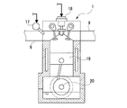
- FIG. 2 is a cross-sectional view showing an outline of an engine according to the first embodiment.
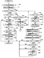
- 4 is a flowchart according to the first embodiment and showing the contents of purge control.
- a fuel cut execution load map according to a first embodiment which is referred to in order to obtain a fuel cut execution load according to an engine rotational speed.
- the time chart which concerns on 1st Embodiment and shows the behavior of the various parameters in purge control.
- the flowchart which concerns on 2nd Embodiment and which shows the content of purge control.
- the time chart which concerns on 2nd Embodiment and shows the behavior of the various parameters in purge control.
- the flowchart which concerns on 3rd Embodiment and which shows the content of purge control The small opening degree map referred in order to obtain
- the flowchart which concerns on 5th Embodiment and shows the content of purge control The time chart which concerns on 5th Embodiment and shows the behavior of the various parameters in purge control.
- require the compressor exit pressure just before deceleration according to 6th Embodiment according to the engine rotational speed and engine load just before deceleration.
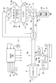
- FIG. 1 is a schematic configuration view of an engine system of this embodiment.
- a gasoline engine system (hereinafter simply referred to as "engine system") mounted on a motor vehicle includes an engine 1 having a plurality of cylinders.
- the engine 1 is a four-cylinder four-cycle reciprocating engine, and includes known configurations such as a piston 19 and a crankshaft 20 (see FIG. 2) described later.
- the engine 1 is provided with an intake passage 2 for introducing intake air to each cylinder, and an exhaust passage 3 for leading exhaust gas from each cylinder.
- a supercharger 5 is provided in the intake passage 2 and the exhaust passage 3.
- an intake port 2a, an air cleaner 4, a compressor 5a of the supercharger 5, an electronic throttle device 6, an intercooler 7, and an intake manifold 8 are provided in this order from the upstream side.
- the electronic throttle device 6 is disposed in the intake passage 2 upstream of the intake manifold 8 and the intercooler 7 and is driven to open and close according to the accelerator operation by the driver to adjust the amount of intake air flowing through the intake passage 2. It has become.
- the electronic throttle device 6 is configured by a motor type motor-operated valve, and detects a throttle valve 6a which is opened and closed by a motor (not shown) and an opening degree (throttle opening degree) TA of the throttle valve 6a. And a throttle sensor 51.
- the throttle sensor 51 corresponds to an example of the valve opening detection means in the disclosed technology.
- the electronic throttle device 6 corresponds to an example of the intake amount adjustment valve in the disclosed technology.
- the intake manifold 8 is disposed immediately upstream of the engine 1 and a plurality of (four) branches for distributing a surge tank 8a into which intake air is introduced and intake air introduced into the surge tank 8a to each cylinder of the engine 1 And a tube 8b.
- an exhaust manifold 9, a turbine 5 b of the turbocharger 5 and two catalysts 10 and 11 arranged in series are provided in this order from the upstream side.
- the two catalysts 10 and 11 are for purifying the exhaust gas, and can be constituted by, for example, a three-way catalyst.
- the supercharger 5 is provided to boost the intake air in the intake passage 2, and as an example, a compressor 5a disposed in the intake passage 2, a turbine 5b disposed in the exhaust passage 3, a compressor 5a and a turbine 5b And a rotation shaft 5c coupled integrally rotatably.
- the turbine 5 b is rotated by the exhaust gas flowing through the exhaust passage 3, and the compressor 5 a is rotationally operated in conjunction with the rotation of the turbine 5 b so that the intake air flowing through the intake passage 2 is pressurized.
- the intercooler 7 is configured to cool the intake air boosted by the compressor 5a.
- the outline of the engine 1 is shown by FIG. 2 by sectional drawing.
- the engine 1 is provided with an injector 17 for injecting fuel corresponding to each cylinder.
- the injector 17 is configured to inject the fuel supplied from the fuel tank 40 (see FIG. 1) for storing the fuel into each cylinder of the engine 1.
- a combustible mixture is formed by the fuel injected from the injector 17 and the intake air introduced from the intake manifold 8.
- the injector 17 and the fuel tank 40 are an example of the components which comprise the fuel supply system in this indication art.
- the engine 1 is provided with an igniter 18 corresponding to each cylinder.
- the igniter 18 is configured to ignite the combustible mixture formed in each cylinder.
- the combustible mixture in each cylinder explodes and burns by the ignition operation of the igniter 18, and the exhaust gas after combustion is exhausted to the outside from each cylinder through the exhaust manifold 9, the turbine 5b and each catalyst 10, 11.
- the piston 19 moves up and down, and the crankshaft 20 rotates, whereby power is obtained for the engine 1.
- the fuel supply system comprises a fuel tank 40 for storing fuel.
- the engine system also includes an evaporative fuel processing device 41 for collecting and processing evaporative fuel (vapor) generated in the fuel tank 40 without being released to the atmosphere.
- the device 41 includes a canister 42, a purge passage 43, a purge pump 44 and a purge valve 45.
- the canister 42 is designed to temporarily collect vapor generated in the fuel tank 40 through the vapor passage 46.
- the canister 42 contains an adsorbent (not shown) that adsorbs vapor.
- the purge passage 43 extends from the canister 42, and its outlet 43a is connected to the intake passage 2 upstream of the compressor 5a.
- the purge pump 44 and the purge valve 45 each have an electric configuration, and are provided in the purge passage 43.
- the purge pump 44 sucks the vapor from the canister 42 and discharges the vapor to the purge passage 43.
- the purge valve 45 is adapted to adjust the vapor flow rate in the purge passage 43.
- An atmosphere port 42 a provided in the canister 42 is adapted to introduce the atmosphere into the canister 42 when the vapor is purged into the purge passage 43.
- the purge pump 44 and the purge valve 45 correspond to an example of the purge adjusting means in this disclosed technique.
- the purge pump 44 and the purge valve 45 are operated.
- the vapor collected in the canister 42 is purged into the intake passage 2 through the purge passage 43.
- the purged vapor is sucked into the engine 1 and subjected to combustion for processing.
- the various sensors 51 to 58 provided in the engine system correspond to an example of the operating state detecting means in the disclosed technique for detecting the operating state of the engine 1.
- An air flow meter 52 provided in the vicinity of the air cleaner 4 detects an intake amount Ga flowing from the air cleaner 4 to the intake passage 2 and outputs an electrical signal according to the detected value.
- An intake pressure sensor 53 provided in the surge tank 8a detects an intake pressure PM downstream of the electronic throttle device 6, and outputs an electrical signal according to the detected value.
- a water temperature sensor 54 provided in the engine 1 detects the temperature (cooling water temperature) THW of the cooling water flowing inside the engine 1 and outputs an electric signal according to the detected value.
- the rotational speed sensor 55 provided in the engine 1 detects the rotational speed of the crankshaft 20 as the rotational speed (engine rotational speed) NE of the engine 1 and outputs an electrical signal according to the detected value.
- the rotational speed sensor 55 corresponds to an example of the rotational speed detection means in the disclosed technique.
- the oxygen sensor 56 provided in the exhaust passage 3 detects the oxygen concentration (output voltage) Ox in the exhaust gas discharged to the exhaust passage 3 and outputs an electrical signal according to the detected value.
- the oxygen sensor 56 corresponds to an example of the air-fuel ratio detection means in the disclosed technology.
- An accelerator sensor 57 is provided on an accelerator pedal 16 provided on the driver's seat.
- the accelerator pedal 16 corresponds to an example of the output operation means in the disclosed technology.
- the accelerator sensor 57 detects the depression angle of the accelerator pedal 16 as the accelerator opening degree ACC, and outputs an electrical signal according to the detected value.
- the accelerator sensor 57 corresponds to an example of the output operation amount detection means in the disclosed technique.
- a vehicle speed sensor 58 provided in the vehicle detects a traveling speed (vehicle speed) SPD of the vehicle, and outputs an electrical signal according to the detected value.
- the engine system includes an electronic control unit (ECU) 60 that controls various controls.
- ECU electronice control unit
- Various sensors 51 to 58 are connected to the ECU 60, respectively.
- the electronic throttle device 6, the injectors 17, the ignition devices 18, the purge pump 44, the purge valve 45, and the like are connected to the ECU 60, respectively.
- the ECU 60 corresponds to an example of control means in the disclosed technology.
- the ECU 60 receives various signals output from the various sensors 51 to 58, and based on these signals, performs each of the injectors to execute fuel injection control including air-fuel ratio control and ignition timing control. 17 and each igniter 18 are controlled respectively. Further, the ECU 60 controls the electronic throttle device 6, the purge pump 44, and the purge valve 45 in order to execute intake control and purge control based on various signals.
- the intake control is to control the amount of intake drawn into the engine 1 by controlling the electronic throttle device 6 based on the detection value of the accelerator sensor 57 according to the operation of the accelerator pedal 16 by the driver. It is.
- the ECU 60 controls the electronic throttle device 6 (throttle valve 6a) from the open state to a predetermined small deceleration opening degree so as to throttle the intake air taken into the engine 1 There is.
- the purge control is to control the purge flow rate of the vapor from the canister 42 to the intake passage 2 by controlling the purge pump 44 and the purge valve 45 according to the operating state of the engine 1.
- the ECU 60 includes a central processing unit (CPU), various memories, an external input circuit, an external output circuit, and the like.
- the memory stores a predetermined control program related to various controls of the engine 1.
- the CPU is configured to execute the various controls described above based on a predetermined control program based on detection values of various sensors 51 to 58 input through the input circuit.
- the path of the intake passage 2 from the outlet 43a of the purge passage 43 to the electronic throttle device 6 is relatively long, and the volume of the path is relatively large. Therefore, when the engine 1 decelerates from the purge execution state, the throttle valve 6a is closed from the open state to a predetermined deceleration opening degree. At this time, even if the purge cut is performed, since the path of the intake passage 2 from the electronic throttle device 6 to the outlet 43a of the purge passage 43 is relatively long, the portion includes the vapor purged before the purge cut is performed. The intake will remain.
- the intake air may be densified, and the residual intake air including vapor may flow back to the upstream side of the compressor 5a and may be expanded. Then, the residual intake air may flow to the engine 1 through the minute opening degree of the electronic throttle device 6 and may flow into the catalysts 10 and 11. Therefore, even if the fuel cut at the same time as the fuel cut at the time of deceleration, residual intake including vapor continues to flow into the catalysts 10 and 11, and the temperature of the catalysts 10 and 11 (catalyst temperature) rises excessively. May be degraded or melted away. Therefore, in this embodiment, the following purge control is performed in order to cope with the above-mentioned problem.
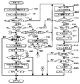
- FIG. 3 is a flowchart showing the control contents.
- step 100 the ECU 60 takes in the accelerator closing speed ⁇ TAACC based on the detection value of the accelerator sensor 57.
- the accelerator closing speed ⁇ TAACC means a change speed when the accelerator pedal 16 being depressed to a certain opening degree returns toward the fully closed position where the depression is not depressed.
- the ECU 60 can obtain this accelerator closing speed ⁇ TAACC from the change speed of the accelerator opening degree ACC.
- the ECU 60 takes in the engine rotational speed NE and the engine load KL based on the detected values of the intake pressure sensor 53, the rotational speed sensor 55 and the like.
- the ECU 60 can obtain the engine load KL from the intake pressure PM and the engine rotational speed NE.
- the ECU 60 determines whether the accelerator closing speed ⁇ TAACC is larger than the first deceleration determination value C1.
- the first deceleration determination value C1 is set to a predetermined value in order to determine the deceleration of the engine 1 early.
- the determination result is affirmative, the ECU 60 can determine that it is not the start of the deceleration of the engine 1 and shifts the processing to step 130.
- the determination result is negative, the ECU 60 can determine that the start of the deceleration of the engine 1 and shifts the processing to step 230.
- step 130 the ECU 60 determines whether the purge cut execution flag XPC is "0". As described later, the purge cut execution flag XPC is set to “1” when the purge cut (P / C) is being performed. If the determination result is affirmative, the ECU 60 can determine that the purge cut is not performed, and shifts the processing to step 140. When the determination result is negative, the ECU 60 can determine that the purge cut is being performed, and shifts the processing to step 200.
- step 140 the ECU 60 determines whether or not a predetermined fuel cut return condition necessary to execute the fuel cut (F / C) is satisfied.
- the ECU 60 shifts the processing to step 150 when the determination result is affirmative, and returns the processing to step 100 when the determination result is negative.
- the ECU 60 executes fuel cut (F / C) return. That is, the ECU 60 returns from the fuel cut to the normal fuel injection control by controlling the injectors 17.
- step 160 the ECU 60 sets the fuel cut execution flag XFC to “0” because the fuel cut is not executed.
- step 170 the ECU 60 determines whether or not a predetermined purge on condition necessary to execute the purge of the vapor is satisfied.
- the ECU 60 transfers the process to step 180 if the determination result is affirmative, and returns the process to step 100 if the determination result is negative.
- step 180 the ECU 60 takes in a predetermined target purge opening degree TPG, and restarts the purge control based on the opening degree TPG.
- the ECU 60 can obtain the target purge opening degree TPG according to the operating state of the engine 1.
- step 190 the ECU 60 sets the purge cut execution flag XPC to “0”, and returns the process to step 100.
- step 200 the ECU 60 determines whether the accelerator closing speed ⁇ TAACC is larger than a second deceleration determination value C2 (C2> C1).
- the accelerator closing speed ⁇ TAACC the first deceleration determination value C1 is faster than the second deceleration determination value C2.
- the determination result is affirmative, the ECU 60 can determine that the engine 1 has changed to acceleration or steady operation, and shifts the processing to step 210.
- the determination result is negative, the ECU 60 can determine that the deceleration of the engine 1 is continuing, and shifts the processing to step 230.
- step 210 the ECU 60 takes in the throttle opening degree TA based on the detection value of the throttle sensor 51.
- the ECU 60 determines whether the throttle opening degree TA is larger than a predetermined deceleration release determination value D1. When the determination result is affirmative, the ECU 60 can determine that the deceleration of the engine 1 has been released, and shifts the processing to step 140. If the determination result is negative, the ECU 60 can determine that the deceleration of the engine 1 is continuing because the throttle opening degree TA is relatively small, and the process proceeds to step 230.
- step 230 the ECU 60 determines whether the purge cut execution flag XPC is "0". If the determination result is affirmative, the ECU 60 can determine that the purge cut is not performed, and shifts the processing to step 240. When the determination result is negative, the ECU 60 can determine that the purge cut is being performed, and jumps the process to step 260.
- the ECU 60 executes a purge cut (P / C). That is, the ECU 60 shuts off the purge of the vapor from the purge passage 43 to the intake passage 2 by controlling the purge pump 44 and the purge valve 45.
- step 250 the ECU 60 sets the purge cut execution flag XPC to "1".
- step 260 the ECU 60 obtains a fuel cut execution load FCKL that corresponds to the engine rotational speed NE and is the engine load KL.
- the ECU 60 can obtain the fuel cut execution load FCKL according to the engine rotational speed NE, for example, by referring to the fuel cut execution load map as shown in FIG. 4. In this map, the fuel cut execution load FCKL is set to be lower as the engine rotational speed NE becomes higher.
- step 270 the ECU 60 determines whether the current engine load KL is smaller than the fuel cut execution load FCKL.
- the ECU 60 shifts the processing to step 280 when the determination result is affirmative, and returns the processing to step 100 when the determination result is negative.
- step 280 the ECU 60 determines whether the engine rotational speed NE is higher than a predetermined value A1. This predetermined value A1 is shown in the map of FIG. If the determination result is affirmative, the ECU 60 shifts the process to step 290 because the engine rotation speed NE is relatively high, and if the determination result is negative, the engine rotation speed NE is relatively low. The process returns to step 100 from step.
- the ECU 60 executes a fuel cut (F / C). That is, the ECU 60 shuts off the fuel injection from the injector 17.
- step 300 the ECU 60 sets the fuel cut execution flag XFC to “1”, and returns the process to step 100.
- the ECU 60 purges the vapor from the purge passage 43 to the intake passage 2 when it is determined that the deceleration of the engine 1 is started based on the detected operating condition of the engine 1 during the operation of the engine 1
- the purge pump 44 and the purge valve 45 are controlled to shut off (purge cut), and then the injector 17 is controlled to shut off the fuel supply to the engine 1 (fuel cut).
- the ECU 60 controls the purge pump 44 and the purge valve 45 to purge the vapor, and then cuts the fuel when it is determined that the engine 1 is in the predetermined operating state. To control the injectors 17.
- the ECU 60 determines the start of the deceleration of the engine 1 based on the accelerator closing speed ⁇ TAACC which is the change speed of the detected accelerator opening degree ACC.
- the ECU 60 determines that the deceleration is to be started, the ECU 60 performs a purge cut of the vapor at a stretch. Thereafter, if the accelerator closing speed ⁇ TAACC is between the first deceleration determination value C1 and the second deceleration determination value C2, execution of the purge cut is continued on the assumption that the deceleration state is continued.
- the ECU 60 continues the execution of the purge cut assuming that the deceleration state continues unless the accelerator opening degree ACC exceeds the deceleration release determination value D1. It is supposed to be. Further, when the return from the fuel cut is executed in a state where the accelerator opening degree ACC does not exceed the deceleration release determination value D1, the ECU 60 restarts the purge control.
- the purge pump 44 and the purge valve 45 are controlled to quickly return to the purge rate.
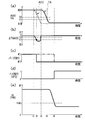
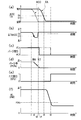
- FIG. 5 is a time chart showing the behavior of various parameters in the above-described purge control.
- (a) shows changes of the accelerator opening degree ACC (broken line) and the throttle opening degree TA (solid line).
- B) shows the change of the accelerator closing speed ⁇ TAACC.
- C) shows the change of the purge execution of vapor (a solid line shows this embodiment, a dashed-two dotted line shows a prior art example, and so on).
- D) shows a change of fuel cut (F / C) execution (fuel cut execution flag XFC).
- (E) shows the change of the engine load KL (also the change of the intake pressure PM).
- FIG. 5 shows changes of the accelerator opening degree ACC (broken line) and the throttle opening degree TA (solid line).
- B shows the change of the accelerator closing speed ⁇ TAACC.
- C shows the change of the purge execution of vapor (a solid line shows this embodiment, a dashed-two dotted line shows a prior art example, and so on
- the fuel injected from the injector 17 is supplied to the engine 1 and the vapor is purged from the purge passage 43 to the intake passage 2
- the electronic throttle device 6 is closed from the open state to the deceleration opening degree, and from the start of the deceleration, intake air including vapor remains in the intake passage 2 upstream from the electronic throttle device 6.
- This residual intake air flows to the engine 1 through the opening degree of the electronic throttle device 6 and flows to the catalysts 10 and 11 in the exhaust passage 3.
- the purge of the vapor is shut off (purge cut) first, and then the supply of fuel is shut off (fuel cut).
- the purge cut is performed before the fuel cut is performed, and the residual intake including the vapor in the intake passage 2 upstream of the electronic throttle device 6 flows to the engine 1 and is scavenged by the engine 1 until the fuel cut. Ru.
- the fuel cut is performed when the engine 1 is in a predetermined operation state (KL ⁇ FCKL, NE> A1). For this reason, it is possible to prevent the operation of the engine 1 from malfunctioning due to the execution of the fuel cut.
- the change speed of the operation amount (accelerator opening degree ACC) of the accelerator pedal 16 (accelerator closing speed ⁇ TAACC) and the change speed of the opening degree of the electronic throttle device 6 (throttle opening degree TA) The start of deceleration of the engine 1 is determined early based on Therefore, the purge cut can be performed from an early time after the start of the deceleration of the engine 1, and the wasteful increase of the vapor in the intake passage 2 upstream of the electronic throttle device 6 can be suppressed.
- the purge rate before the execution of the purge cut is promptly returned. Therefore, it is possible to suppress an excessive rise in the catalyst temperature without reducing the purge flow rate of the vapor.
- FIG. 6 is a flowchart showing the contents of the purge control.
- This embodiment differs from the configuration of the flowchart of FIG. 3 in that the processing of steps 400 and 410 is added before the processing of step 230 in the flowchart of FIG.
- step 400 the ECU 60 takes in the throttle opening degree TA based on the detection value of the throttle sensor 51.
- the ECU 60 determines whether the throttle opening degree TA is smaller than a predetermined small opening degree D2 (D2> D1). That is, after the ECU 60 determines that the deceleration of the engine 1 is started based on the accelerator closing speed ⁇ TAACC at step 120, the throttle valve 6a becomes smaller than the predetermined small opening degree D2 after the deceleration starts at this step 410. Will wait. If the determination result is affirmative, the ECU 60 shifts the process to step 230 in order to sequentially execute the purge cut and the fuel cut of the vapor. Further, when the determination result is negative, the ECU 60 returns the process to step 100.
- D2 a predetermined small opening degree D2
- the ECU 60 determines and detects the start of deceleration of the engine 1 based on the accelerator closing speed ⁇ TAACC that is the change speed of the detected accelerator opening ACC.
- the purge pump 44 and the purge valve 45 are controlled to perform the purge cut of the vapor.
- FIG. 7 is a time chart showing the behavior of various parameters in the above-described purge control.
- the types of parameters (a) to (e) are the same as those in FIG.
- the throttle opening degree TA which has started to decrease after the full closing of the accelerator opening degree ACC, has a predetermined throttle opening degree TA of (a) smaller than a predetermined small opening degree D2 at time t4.
- the purge cut is executed when the deceleration release judgment value D1 of the above is dropped. Thereafter, when the engine load KL of (e) falls below the fuel cut execution load FCKL with the throttle opening degree TA of (a) reaching the minimum deceleration opening degree at time t5, the fuel cut of (d) (F) / C) is executed.
- the purge cut is performed when the throttle opening TA falls below a predetermined deceleration release determination value D1.
- the following operations and effects can be obtained in addition to the operations and effects of the first embodiment. That is, the start of deceleration of the engine 1 is determined based on the accelerator closing speed ⁇ TAACC, and the purge cut of the vapor is performed when the throttle opening degree TA becomes smaller than the predetermined small opening degree D2. Therefore, vapor remaining in the intake passage 2 upstream of the electronic throttle device 6 flows to the engine 1 until the throttle opening degree TA becomes smaller than the predetermined small opening degree D2. Therefore, almost all the vapor remaining in the intake passage 2 upstream of the electronic throttle device 6 can be flowed to the engine 1 to be scavenged. In this case, as a result, the purge flow rate of the vapor can be increased.
- FIG. 8 is a flowchart showing the contents of the purge control.
- This embodiment differs from the configurations of the flowcharts of FIGS. 3 and 6 in that the processing of steps 420 to 440 is added before the processing of step 230 in the flowchart of FIG.
- the ECU 60 determines the small opening degree D2NE according to the engine rotational speed NE.
- the ECU 60 can obtain the small opening degree D2NE corresponding to the engine rotational speed NE, for example, by referring to the small opening degree map as shown in FIG. In this map, the small opening degree D2NE is set to increase in a curved manner as the engine rotational speed NE increases.
- step 430 the ECU 60 takes in the throttle opening degree TA based on the detection value of the throttle sensor 51.
- step 440 the ECU 60 determines whether the throttle opening degree TA is smaller than the calculated small opening degree D2NE. That is, after ECU 60 determines in step 120 that deceleration of engine 1 is to be started based on accelerator closing speed ⁇ TAACC, in step 440, throttle valve 6a has a small opening degree corresponding to engine rotational speed NE after deceleration starts. It will wait to become smaller than D2NE. If the determination result is affirmative, the ECU 60 shifts the process to step 230 in order to sequentially execute the purge cut and the fuel cut of the vapor. Further, when the determination result is negative, the ECU 60 returns the process to step 100.
- the predetermined small opening degree D2NE to be compared with the throttle opening degree TA is the engine rotational speed The higher the NE, the larger the setting.
- the following operations and effects can be obtained in addition to the operations and effects of the second embodiment. That is, the amount of the vapor remaining in the intake passage 2 upstream of the electronic throttle device 6 at the time of deceleration of the engine 1 increases to the engine 1 as the engine rotation speed NE increases.
- the predetermined small opening degree D2NE to be compared with the throttle opening degree TA is set larger as the engine rotation speed NE becomes higher. Execution time of the purge cut is adjusted. Therefore, the purge cut can be performed at an optimal timing at which the scavenging of the vapor remaining on the upstream side of the electronic throttle device 6 can be completed.
- FIG. 10 is a flowchart showing the contents of the purge control.
- the flow chart of FIG. 10 is the flow chart of FIG. 3 in that the processing of steps 450 to 480 is added between step 120 and step 230, and the processing of steps 490 and 500 is added after step 300.
- the flow chart and configuration are different.
- the process proceeds from step 120, and in step 450, the ECU 60 takes in the actual injection rate FAFVP before the deceleration fuel cut (F / C).
- the actual injection rate FAFVP is a value obtained by dividing the actual injection amount (stoichiometry) actually injected from the injector 17 by the basic injection amount (stoichiometry) with respect to the intake amount Ga.
- the ECU 60 takes in the catalyst temperature TEP.
- the ECU 60 can estimate the catalyst temperature TEP based on the fuel injection amount supplied from the injector 17 to the engine 1 or the like.
- the ECU 60 obtains an increase ⁇ TEP of the catalyst temperature from the captured actual injection rate FAFVP.
- the ECU 60 can obtain the increase ⁇ TEP of the catalyst temperature according to the actual injection rate FAFVP, for example, by referring to the catalyst temperature rise map shown in FIG. In this map, the increase ⁇ TEP in the catalyst temperature is set to decrease in a curvilinear manner as the actual injection rate FAFVP increases from “0.5” to “1.0”.
- the ECU 60 determines whether the addition result of the catalyst temperature TEP and the catalyst temperature increase ⁇ TEP is higher than a predetermined reference temperature T1.
- a predetermined reference temperature T1 for example, “750 ° C.” corresponding to the criteria for deterioration of the catalysts 10 and 11 can be applied.
- the ECU 60 shifts the processing to step 230 if the determination result is affirmative, and jumps the processing to step 260 if the determination result is negative.
- the ECU 60 executes purge cut (P / C). That is, the ECU 60 shuts off the purge of the vapor from the purge passage 43 to the intake passage 2 by controlling the purge pump 44 and the purge valve 45.
- step 500 the ECU 60 sets the purge cut execution flag XPC to “1”, and returns the process to step 100.
- the ECU 60 determines that the deceleration of the engine 1 is started during the operation of the engine 1, the ECU 60 detects the operation state of the engine 1 detected. The temperature is estimated, and the purge pump 44 and the purge valve 45 are controlled to perform vapor purge cut when the estimated temperatures of the catalysts 10 and 11 become higher than a predetermined reference temperature T1.
- the overheating of the catalysts 10 and 11 is a problem mainly because the temperature of the catalyst (the sum of the catalyst temperature TEP and the increase ⁇ TEP of the catalyst temperature) corresponds to the predetermined reference temperature T1 (for example, the criteria for catalyst deterioration It is time to get higher.
- the purge cut of vapor is executed when the estimated catalyst temperature TEP becomes higher than the predetermined reference temperature T1
- the purge cut is executed in accordance with the temperature state of the catalysts 10 and 11. Therefore, the timing of the purge cut can be extended to a temperature at which the catalysts 10 and 11 may overheat. In this case, as a result, the purge flow rate of the vapor can be increased.
- FIG. 12 is a flowchart showing the contents of the purge control.
- the flowchart of FIG. 12 omits steps 180 and 190 in the flowchart of FIG. 3, and instead provides the processing of steps 510 to 560, and performs steps 570 to 570 between steps 230 and 240 of the flowchart of FIG.
- the configuration is different from that of the flowchart of FIG. 3 in that processing of 590 is added.
- step 510 the ECU 60 takes in the target purge rate TPG%.
- the ECU 60 can obtain the target purge rate TPG% based on the operating state of the engine 1.
- step 520 the ECU 60 sets the actual actual purge rate PG% to "0".
- step 530 the ECU 60 determines the actual purge rate PG% (i) by adding a predetermined value ⁇ to the actual purge rate PG% (i-1) obtained last time, and the actual purge rate PG% ( Execute purge restart control according to i). That is, the ECU 60 controls the purge pump 44 and the purge valve 45 so that the actual purge rate PG% (i) is obtained.
- step 540 the ECU 60 determines whether the target purge rate TPG% is equal to or less than the actual purge rate PG%. If the determination result is affirmative, the ECU 60 shifts the processing to step 550 on the assumption that the purge restart is completed, and if the determination result is negative, the processing on the step 530 is regarded as incomplete purge restart. Return to.
- the ECU 60 sets the value of the target purge rate TPG% as the value of the actual purge rate PG%.
- step 560 the ECU 60 sets the purge cut execution flag XPC to “0”, assuming that the purge restart control is completed, and returns the process to step 100.
- step 230 determines whether the purge rate PG% is negative. If the determination result in step 230 is affirmative, the ECU 60 takes in the actual purge rate PG% in step 570.
- the ECU 60 determines the actual purge rate PG% (i) by subtracting the predetermined value ⁇ from the actual purge rate PG% (i-1) obtained last time, and the actual purge rate PG% ( Purge rate damping control is executed according to i). That is, the ECU 60 controls the purge pump 44 and the purge valve 45 so that the actual purge rate PG% (i) is obtained.
- step 590 the ECU 60 determines whether the actual purge rate PG% is equal to or less than "0". If the determination result is affirmative, the ECU 60 moves the process to step 240, assuming that the purge cut is completed, and if the determination result is negative, repeats the process of step 590 as the purge cut incomplete. .
- the ECU 60 performs the purge pump 44 and the purge valve 45 so that the purge rate PG% of the vapor gradually decreases when performing the purge cut of the vapor. It is supposed to control.
- the ECU 60 after performing the purge cut of the vapor in addition to the control of the first embodiment, gradually increases the purge rate PG% of the vapor when resuming the purge.
- the purge pump 44 and the purge valve 45 are controlled at the same time.
- FIG. 13 is a time chart showing the behavior of various parameters in the above-described purge control.
- (a) shows changes in the accelerator opening degree ACC (broken line) and the throttle opening degree TA (solid line).
- B) shows the change of the accelerator closing speed ⁇ TAACC.
- C) shows the change of the purge execution of vapor.
- D shows the change of the purge rate PG%.
- (E) shows a change of fuel cut (F / C) execution (fuel cut execution flag XFC).
- F) shows the change of the engine load KL (also the change of the intake pressure PM).
- the following operations and effects can be obtained in addition to the operations and effects of the first embodiment. That is, since the volume of the intake passage 2 upstream of the electronic throttle device 6 is relatively large, when the purge cut of vapor is executed at once, there is intake air remaining in the intake passage 2 upstream of the electronic throttle device 6 after the purge cut. It is difficult to predict the timing of the flow to the engine 1. On the other hand, since the engine 1 is operated by the fuel injected from the injector 17 and the vapor to be purged, the air-fuel ratio becomes over-leaned when the vapor is lost at a stroke by execution of the purge cut, and the engine 1 is misfired.
- the purge rate PG% is adjusted so as to gradually decrease, so that the vapor flowing to the engine 1 does not disappear at a stretch. Therefore, it is possible to prevent the air-fuel ratio from being over-leaned or the temperature of the catalysts 10, 11 from rising due to the execution of the purge cut when the engine is decelerating.
- the purge rate PG% is adjusted to gradually increase, so that the vapor flowing to the engine 1 does not increase at a stretch. For this reason, it is possible to prevent the air-fuel ratio from becoming over-rich and the exhaust emission from deteriorating due to the restart of the purge at the time of operation of the engine.
- FIG. 14 shows the contents of the purge control in the form of a flowchart.
- the flowchart of FIG. 14 differs from the flowchart of FIG. 3 in that the process of steps 600 to 630 is provided between step 260 and step 270 in the flowchart of FIG.
- step 600 the ECU 60 obtains the outlet pressure (compressor outlet pressure) PC of the compressor 5a just before deceleration from the engine rotational speed NE just before deceleration and the engine load KL.
- the ECU 60 can obtain the compressor outlet pressure PC immediately before deceleration according to the engine rotational speed NE immediately before deceleration and the engine load KL, for example, by referring to the outlet pressure map as shown in FIG.
- FIG. 16 is a graph showing the relationship between the compressor outlet pressure PC immediately before deceleration and the residual intake air amount VGa immediately after deceleration.
- the residual intake air amount VGa in the non-supercharged region from low pressure to atmospheric pressure, the residual intake air amount VGa becomes a predetermined constant a regardless of the compressor outlet pressure PC, and in the supercharged region, the compressor outlet pressure PC increases. It increases linearly with it.
- the ECU 60 can obtain the residual intake amount VGa immediately after deceleration according to the compressor outlet pressure PC immediately before deceleration by referring to the characteristic map according to the characteristics of the graph shown in FIG.
- the ECU 60 obtains an integrated passing intake amount TGaT that has passed through the throttle valve 6a after the start of deceleration.
- the ECU 60 can obtain the integrated passing intake amount TGaT by integrating the intake amount Ga per unit time detected by the air flow meter 52 from the start of deceleration.
- the ECU 60 determines whether the calculated value obtained by adding a predetermined value ⁇ to the difference between the residual intake amount VGa and the integrated passage intake amount TGaT is equal to or less than “0”.
- the ECU 60 determines the scavenging state of the remaining intake air in the intake passage 2 upstream of the electronic throttle device 6. If the determination result is affirmative, the ECU 60 assumes that scavenging of residual intake air has been completed, and the process proceeds to step 270. If the determination result is negative, scavenging of residual intake air is not completed. The process returns to step 100 as.
- the ECU 60 controls the purge pump 44 and the purge valve 45 in order to purge the vapor in addition to the control of the first embodiment, and then based on the operating state of the engine 1 detected.
- the fuel cut is determined after determining the residual intake amount VGa including residual air remaining in the intake passage 2 upstream of the electronic throttle device 6 (residual intake amount) VGa and determining that scavenging of the residual intake of that amount is completed.
- the injectors 17 are controlled.
- FIG. 17 is a time chart showing the behavior of various parameters in the above-described purge control.
- (a) shows changes of the accelerator opening degree ACC (broken line) and the throttle opening degree TA (solid line).
- B) shows the change of the accelerator closing speed ⁇ TAACC.
- C) shows the change of the purge execution of vapor.
- (D) shows a change of fuel cut (F / C) execution (fuel cut execution flag XFC).
- E) shows the change of the integrated passing intake amount TGaT (reduction of the residual intake amount VGa).
- (F) shows the change of the engine load KL (also the change of the intake pressure PM).
- FIG. 17 shows changes of the accelerator opening degree ACC (broken line) and the throttle opening degree TA (solid line).
- B shows the change of the accelerator closing speed ⁇ TAACC.
- C shows the change of the purge execution of vapor.
- (D) shows a change of fuel cut (F / C) execution (fuel cut execution flag
- the residual intake amount VGa decreases, the residual intake disappears (scavenging completion), and the engine load KL is a fuel cut execution load in a state in which the throttle valve 6a is closed to the deceleration opening after the accelerator opening ACC is fully closed. It can be seen that a fuel cut is carried out at once if it is below FCKL.
- the following operations and effects can be obtained in addition to the operations and effects of the first embodiment. That is, after the purge cut of the vapor is performed, the residual intake amount VGa including the vapor remaining in the intake passage 2 upstream of the electronic throttle device 6 is determined, and after scavenging of the residual intake of the amount VGa is completed, A fuel cut is performed. Therefore, the purge cut is performed, and the fuel cut is performed after the residual intake including the vapor is surely eliminated from the intake passage 2 upstream of the electronic throttle device 6.
- the present embodiment differs from the sixth embodiment in the content of the purge control.
- 18 and 19 show the contents of the purge control in the form of flowcharts. 18 and 19 adds the processing of step 640 and step 650 between step 120 and step 230 in the flowchart of FIG. 14, and step 700 between step 630 and step 270 of the flowchart of FIG.
- the configuration is different from that of the flowchart of FIG. 14 in that the processing of step 820 is added.
- step 640 the ECU 60 takes in a purge cut delay time KP described later after the deceleration determination in step 120.
- step 650 the ECU 60 shifts the process to step 230 after waiting for the purge cut delay time KP to elapse after the deceleration determination.
- step 630 determines an air-fuel ratio correction coefficient FAF at stoichiometry in step 700.
- the ECU 60 can obtain the air-fuel ratio correction coefficient FAF based on the oxygen concentration Ox detected by the oxygen sensor 56 in air-fuel ratio control of the engine 1 which is separately executed.
- the ECU 60 determines whether the air-fuel ratio correction flag XFAF is "0".
- the flag XFAF is set to "1" when the air-fuel ratio correction coefficient FAF converges to a certain value due to the purge cut of the vapor as described later.
- the ECU 60 shifts the processing to step 720 when the determination result is affirmative, and jumps the processing to step 270 when the determination result is negative.
- step 720 the ECU 60 determines whether there is a change in the air-fuel ratio correction coefficient FAF.
- the ECU 60 shifts the process to step 730 when the determination result is affirmative, and shifts the process to step 790 when the determination result is negative.
- step 730 the ECU 60 determines whether the air-fuel ratio correction coefficient FAF has been increased.
- the ECU 60 shifts the process to step 740 if the determination result is affirmative, and jumps the process to step 270 if the determination result is negative.
- the ECU 60 determines whether the change of the air-fuel ratio correction coefficient FAF has converged to a certain value.
- the ECU 60 shifts the processing to step 750 when the determination result is affirmative, and jumps the processing to step 270 when the determination result is negative.
- step 750 the ECU 60 determines whether a fuel cut (F / C) has been performed within "one second" after the convergence of the air-fuel ratio correction coefficient FAF.
- the ECU 60 transfers the process to step 760 if the determination result is affirmative, and transfers the process to step 780 if the determination result is negative.
- the ECU 60 calculates a purge cut delay time KP.
- the previous purge cut delay time KP (i-1) is taken as the current purge cut delay time KP.
- step 770 the ECU 60 sets the air-fuel ratio correction flag XFAF to "1", and then shifts the processing to step 270.
- step 780 the ECU 60 calculates the purge cut delay time KP.
- the result of adding “0.5 seconds” to the previous purge cut delay time KP (i ⁇ 1) is taken as the current purge cut delay time KP. "0.5 seconds" of the addition value is an example.
- the ECU 60 transfers the process to step 770.
- step 790 after transitioning from step 720, the ECU 60 determines whether fuel cut (F / C) has been performed without changing the air-fuel ratio correction coefficient FAF.
- the ECU 60 shifts the processing to step 800 when the determination result is affirmative, and shifts the processing to step 770 when the determination result is negative.
- the ECU 60 calculates a purge cut delay time KP.
- the result of subtracting “0.5 seconds” from the previous purge cut delay time KP (i ⁇ 1) is taken as the current purge cut delay time KP.
- the subtraction value “0.5 seconds” is an example.
- the ECU 60 determines whether the purge cut delay time KP is smaller than "0", that is, a negative value.
- the ECU 60 transfers the process to step 820 if the determination result is affirmative, and transfers the process to step 770 if the determination result is negative.
- step 820 the ECU 60 sets the purge cut delay time KP to "0", and then shifts the processing to step 770.
- the ECU 60 determines the purge cut delay time KP for delaying the purge cut of the vapor based on the detected change in the air fuel ratio (air fuel ratio correction coefficient FAF)
- the purge pump 44 and the purge valve 45 are controlled to perform the purge cut of the vapor after the purge cut delay time KP elapses.
- FIG. 20 is a time chart showing the behavior of various parameters in the above-described purge control.
- (a) shows changes of the accelerator opening degree ACC (broken line) and the throttle opening degree TA (solid line).
- B) shows the change of the accelerator closing speed ⁇ TAACC.
- C) shows the change of the purge execution of vapor.
- (D) shows a change of fuel cut (F / C) execution (fuel cut execution flag XFC).
- E) shows the change of the integrated passing intake amount TGaT (reduction of the residual intake amount VGa).
- (F) shows the change of the air-fuel ratio correction coefficient FAF.
- (G) shows the change of the engine load KL (also the change of the intake pressure PM).
- the convergence of the air-fuel ratio of the engine 1 is caused by the scavenging condition of the intake (residual intake) including the vapor remaining in the intake passage 2 upstream of the electronic throttle device 6 when the engine 1 decelerates.
- the next purge cut timing is delayed by the purge cut delay time KP from the judgment of the deceleration start.
- the following operations and effects can be obtained in addition to the operations and effects of the sixth embodiment. That is, if the purge cut is performed too early, this leads to a decrease in the flow rate of the purge supplied to the engine 1, and if the purge cut is performed too late, this will lead to an increase in the catalyst temperature.
- the timing at which the temperature of the catalyst 10, 11 rises due to the inflow of the vapor is predicted by the purge cut delay time KP. Then, after the purge cut delay time KP has elapsed, the purge cut of the vapor is executed.
- the execution timing of the purge cut is adjusted in accordance with the timing of the temperature rise of the catalysts 10 and 11. Therefore, since the execution time of the purge cut can be optimized in accordance with the temperature rise of the catalysts 10 and 11, it is possible to achieve both the suppression of the purge flow rate decrease and the suppression of the temperature rise of the catalysts 10 and 11.
- the start of deceleration of the engine 1 is determined based on the accelerator closing speed ⁇ TAACC, which is the change speed of the accelerator opening ACC, but the change speed of the throttle opening TA detected by the accelerator sensor 57 It is also possible to determine the start of deceleration of the engine 1 based on the above.
- the engine system is embodied in an engine system not provided with an EGR device.
- the engine system may be embodied in an engine system provided with an EGR device.
- the disclosed technology can be applied to an engine system provided with an engine, a supercharger, an intake amount adjustment valve, and an evaporative fuel processing device.
Landscapes
- Engineering & Computer Science (AREA)
- Chemical & Material Sciences (AREA)
- Combustion & Propulsion (AREA)
- Mechanical Engineering (AREA)
- General Engineering & Computer Science (AREA)
- Supplying Secondary Fuel Or The Like To Fuel, Air Or Fuel-Air Mixtures (AREA)
- Output Control And Ontrol Of Special Type Engine (AREA)
- Electrical Control Of Air Or Fuel Supplied To Internal-Combustion Engine (AREA)
- Combined Controls Of Internal Combustion Engines (AREA)
- Supercharger (AREA)
Abstract
L'invention concerne un système de moteur pourvu : d'un moteur (1) ; d'un injecteur (17); d'un compresseur d'alimentation (5) (comprenant un compresseur (5a)) ; d'un dispositif d'étranglement électronique (6) disposé dans un passage d'admission d'air (2), le compresseur (5a) étant disposé dans le passage d'admission d'air (2) en amont du dispositif d'étranglement électronique (6) ; d'un dispositif de traitement de carburant évaporé (41) (comprenant une cartouche (42), un chemin d'écoulement de purge (43) et une vanne de purge (45)), une sortie (43a) du trajet d'écoulement de purge (43) étant reliée au passage d'admission d'air (2) en amont du compresseur (5a) ; et d'un dispositif de commande électronique (ECU) (60). L'ECU (60) commande la vanne de purge (45) afin d'effectuer une coupure de purge de la vapeur à partir du passage de purge (43) vers le passage d'admission d'air (2) lorsqu'il est déterminé qu'une réduction de vitesse du moteur (1) a commencé, et commande ensuite l'injecteur (17) afin d'effectuer une coupure de carburant au moteur (1).
Priority Applications (2)
| Application Number | Priority Date | Filing Date | Title |
|---|---|---|---|
| US16/642,072 US20200217262A1 (en) | 2017-09-20 | 2018-07-03 | Engine system |
| CN201880060947.8A CN111108283A (zh) | 2017-09-20 | 2018-07-03 | 发动机系统 |
Applications Claiming Priority (2)
| Application Number | Priority Date | Filing Date | Title |
|---|---|---|---|
| JP2017180533A JP2019056318A (ja) | 2017-09-20 | 2017-09-20 | エンジンシステム |
| JP2017-180533 | 2017-09-20 |
Publications (1)
| Publication Number | Publication Date |
|---|---|
| WO2019058705A1 true WO2019058705A1 (fr) | 2019-03-28 |
Family
ID=65809647
Family Applications (1)
| Application Number | Title | Priority Date | Filing Date |
|---|---|---|---|
| PCT/JP2018/025136 Ceased WO2019058705A1 (fr) | 2017-09-20 | 2018-07-03 | Système de moteur |
Country Status (4)
| Country | Link |
|---|---|
| US (1) | US20200217262A1 (fr) |
| JP (1) | JP2019056318A (fr) |
| CN (1) | CN111108283A (fr) |
| WO (1) | WO2019058705A1 (fr) |
Cited By (1)
| Publication number | Priority date | Publication date | Assignee | Title |
|---|---|---|---|---|
| CN112576417A (zh) * | 2020-12-09 | 2021-03-30 | 亚普汽车部件股份有限公司 | 一种电控阀、电控阀总成、电控燃油系统及加注控制方法 |
Families Citing this family (2)
| Publication number | Priority date | Publication date | Assignee | Title |
|---|---|---|---|---|
| KR20200127640A (ko) * | 2019-05-03 | 2020-11-11 | 현대자동차주식회사 | 액티브 퍼지 시스템 및 액티브 퍼지 방법 |
| JP2021099036A (ja) * | 2019-12-20 | 2021-07-01 | トヨタ自動車株式会社 | エンジン装置 |
Citations (2)
| Publication number | Priority date | Publication date | Assignee | Title |
|---|---|---|---|---|
| JPH06221234A (ja) * | 1993-01-29 | 1994-08-09 | Honda Motor Co Ltd | 内燃機関の蒸発燃料制御装置 |
| JP2006242161A (ja) * | 2005-03-07 | 2006-09-14 | Toyota Motor Corp | 過給機付きリーンバーンエンジンのパージ制御方法 |
Family Cites Families (2)
| Publication number | Priority date | Publication date | Assignee | Title |
|---|---|---|---|---|
| JP5936469B2 (ja) * | 2012-07-17 | 2016-06-22 | 愛三工業株式会社 | エンジンの制御装置 |
| JP2017129073A (ja) * | 2016-01-21 | 2017-07-27 | トヨタ自動車株式会社 | パージ装置 |
-
2017
- 2017-09-20 JP JP2017180533A patent/JP2019056318A/ja active Pending
-
2018
- 2018-07-03 US US16/642,072 patent/US20200217262A1/en not_active Abandoned
- 2018-07-03 WO PCT/JP2018/025136 patent/WO2019058705A1/fr not_active Ceased
- 2018-07-03 CN CN201880060947.8A patent/CN111108283A/zh not_active Withdrawn
Patent Citations (2)
| Publication number | Priority date | Publication date | Assignee | Title |
|---|---|---|---|---|
| JPH06221234A (ja) * | 1993-01-29 | 1994-08-09 | Honda Motor Co Ltd | 内燃機関の蒸発燃料制御装置 |
| JP2006242161A (ja) * | 2005-03-07 | 2006-09-14 | Toyota Motor Corp | 過給機付きリーンバーンエンジンのパージ制御方法 |
Cited By (1)
| Publication number | Priority date | Publication date | Assignee | Title |
|---|---|---|---|---|
| CN112576417A (zh) * | 2020-12-09 | 2021-03-30 | 亚普汽车部件股份有限公司 | 一种电控阀、电控阀总成、电控燃油系统及加注控制方法 |
Also Published As
| Publication number | Publication date |
|---|---|
| US20200217262A1 (en) | 2020-07-09 |
| JP2019056318A (ja) | 2019-04-11 |
| CN111108283A (zh) | 2020-05-05 |
Similar Documents
| Publication | Publication Date | Title |
|---|---|---|
| JP5936469B2 (ja) | エンジンの制御装置 | |
| CN105986911B (zh) | 用于内燃发动机的控制器和控制方法 | |
| JP4446804B2 (ja) | 内燃機関の制御装置 | |
| JP6282543B2 (ja) | 蒸発燃料供給装置 | |
| JP6041753B2 (ja) | エンジンの排気還流装置 | |
| JP6093258B2 (ja) | 過給機付きエンジンの排気還流装置のための故障検出装置 | |
| JP2011252466A (ja) | 内燃機関のアイドルストップ時のパージ装置 | |
| JP6123815B2 (ja) | エンジンの制御装置 | |
| JP7147377B2 (ja) | 蒸発燃料処理装置 | |
| JP2019027296A (ja) | エンジンシステム | |
| US10941720B2 (en) | Control device for internal-combustion engine | |
| JP6744245B2 (ja) | エンジンシステム | |
| WO2019058705A1 (fr) | Système de moteur | |
| JP6350425B2 (ja) | エンジンの制御装置 | |
| JP6282544B2 (ja) | 蒸発燃料供給装置 | |
| JP6049563B2 (ja) | エンジンの制御装置 | |
| JP6299801B2 (ja) | エンジンの制御装置 | |
| JP6005543B2 (ja) | 過給機付きエンジンの制御装置 | |
| JP2019049219A (ja) | エンジンシステム | |
| JP6005534B2 (ja) | 過給機付きエンジンの制御装置 | |
| JP4501761B2 (ja) | 内燃機関の制御装置 | |
| JP2021195911A (ja) | エンジン装置 | |
| JP2005248913A (ja) | 内燃機関の制御装置 | |
| KR20180067898A (ko) | 엔진의 소기 제어 시의 배기 가스 저감 방법 | |
| JP2019044618A (ja) | エンジンシステム |
Legal Events
| Date | Code | Title | Description |
|---|---|---|---|
| 121 | Ep: the epo has been informed by wipo that ep was designated in this application |
Ref document number: 18859425 Country of ref document: EP Kind code of ref document: A1 |
|
| NENP | Non-entry into the national phase |
Ref country code: DE |
|
| 122 | Ep: pct application non-entry in european phase |
Ref document number: 18859425 Country of ref document: EP Kind code of ref document: A1 |