WO2019058813A1 - 液体入り容器の製造方法 - Google Patents
液体入り容器の製造方法 Download PDFInfo
- Publication number
- WO2019058813A1 WO2019058813A1 PCT/JP2018/030199 JP2018030199W WO2019058813A1 WO 2019058813 A1 WO2019058813 A1 WO 2019058813A1 JP 2018030199 W JP2018030199 W JP 2018030199W WO 2019058813 A1 WO2019058813 A1 WO 2019058813A1
- Authority
- WO
- WIPO (PCT)
- Prior art keywords
- liquid
- container
- rod
- preform
- discharge
- Prior art date
- Legal status (The legal status is an assumption and is not a legal conclusion. Google has not performed a legal analysis and makes no representation as to the accuracy of the status listed.)
- Ceased
Links
Images

Classifications
-
- B—PERFORMING OPERATIONS; TRANSPORTING
- B29—WORKING OF PLASTICS; WORKING OF SUBSTANCES IN A PLASTIC STATE IN GENERAL
- B29C—SHAPING OR JOINING OF PLASTICS; SHAPING OF MATERIAL IN A PLASTIC STATE, NOT OTHERWISE PROVIDED FOR; AFTER-TREATMENT OF THE SHAPED PRODUCTS, e.g. REPAIRING
- B29C49/00—Blow-moulding, i.e. blowing a preform or parison to a desired shape within a mould; Apparatus therefor
- B29C49/42—Component parts, details or accessories; Auxiliary operations
- B29C49/46—Component parts, details or accessories; Auxiliary operations characterised by using particular environment or blow fluids other than air
-
- B—PERFORMING OPERATIONS; TRANSPORTING
- B29—WORKING OF PLASTICS; WORKING OF SUBSTANCES IN A PLASTIC STATE IN GENERAL
- B29C—SHAPING OR JOINING OF PLASTICS; SHAPING OF MATERIAL IN A PLASTIC STATE, NOT OTHERWISE PROVIDED FOR; AFTER-TREATMENT OF THE SHAPED PRODUCTS, e.g. REPAIRING
- B29C49/00—Blow-moulding, i.e. blowing a preform or parison to a desired shape within a mould; Apparatus therefor
- B29C49/08—Biaxial stretching during blow-moulding
- B29C49/10—Biaxial stretching during blow-moulding using mechanical means for prestretching
- B29C49/12—Stretching rods
-
- B—PERFORMING OPERATIONS; TRANSPORTING
- B29—WORKING OF PLASTICS; WORKING OF SUBSTANCES IN A PLASTIC STATE IN GENERAL
- B29C—SHAPING OR JOINING OF PLASTICS; SHAPING OF MATERIAL IN A PLASTIC STATE, NOT OTHERWISE PROVIDED FOR; AFTER-TREATMENT OF THE SHAPED PRODUCTS, e.g. REPAIRING
- B29C49/00—Blow-moulding, i.e. blowing a preform or parison to a desired shape within a mould; Apparatus therefor
- B29C49/42—Component parts, details or accessories; Auxiliary operations
- B29C49/46—Component parts, details or accessories; Auxiliary operations characterised by using particular environment or blow fluids other than air
- B29C2049/4602—Blowing fluids
- B29C2049/465—Blowing fluids being incompressible
- B29C2049/4664—Blowing fluids being incompressible staying in the final article
-
- B—PERFORMING OPERATIONS; TRANSPORTING
- B29—WORKING OF PLASTICS; WORKING OF SUBSTANCES IN A PLASTIC STATE IN GENERAL
- B29C—SHAPING OR JOINING OF PLASTICS; SHAPING OF MATERIAL IN A PLASTIC STATE, NOT OTHERWISE PROVIDED FOR; AFTER-TREATMENT OF THE SHAPED PRODUCTS, e.g. REPAIRING
- B29C2949/00—Indexing scheme relating to blow-moulding
- B29C2949/07—Preforms or parisons characterised by their configuration
- B29C2949/0715—Preforms or parisons characterised by their configuration the preform having one end closed
-
- B—PERFORMING OPERATIONS; TRANSPORTING
- B29—WORKING OF PLASTICS; WORKING OF SUBSTANCES IN A PLASTIC STATE IN GENERAL
- B29C—SHAPING OR JOINING OF PLASTICS; SHAPING OF MATERIAL IN A PLASTIC STATE, NOT OTHERWISE PROVIDED FOR; AFTER-TREATMENT OF THE SHAPED PRODUCTS, e.g. REPAIRING
- B29C49/00—Blow-moulding, i.e. blowing a preform or parison to a desired shape within a mould; Apparatus therefor
- B29C49/02—Combined blow-moulding and manufacture of the preform or the parison
- B29C49/06—Injection blow-moulding
-
- B—PERFORMING OPERATIONS; TRANSPORTING
- B29—WORKING OF PLASTICS; WORKING OF SUBSTANCES IN A PLASTIC STATE IN GENERAL
- B29C—SHAPING OR JOINING OF PLASTICS; SHAPING OF MATERIAL IN A PLASTIC STATE, NOT OTHERWISE PROVIDED FOR; AFTER-TREATMENT OF THE SHAPED PRODUCTS, e.g. REPAIRING
- B29C49/00—Blow-moulding, i.e. blowing a preform or parison to a desired shape within a mould; Apparatus therefor
- B29C49/08—Biaxial stretching during blow-moulding
- B29C49/10—Biaxial stretching during blow-moulding using mechanical means for prestretching
- B29C49/12—Stretching rods
- B29C49/121—Stretching rod configuration, e.g. geometry; Stretching rod material
- B29C49/1212—Stretching rod configuration, e.g. geometry; Stretching rod material the stretching rod comprising at least one opening on the surface, e.g. through which compressed air is blown into the preform to expand the same
-
- B—PERFORMING OPERATIONS; TRANSPORTING
- B29—WORKING OF PLASTICS; WORKING OF SUBSTANCES IN A PLASTIC STATE IN GENERAL
- B29K—INDEXING SCHEME ASSOCIATED WITH SUBCLASSES B29B, B29C OR B29D, RELATING TO MOULDING MATERIALS OR TO MATERIALS FOR MOULDS, REINFORCEMENTS, FILLERS OR PREFORMED PARTS, e.g. INSERTS
- B29K2023/00—Use of polyalkenes or derivatives thereof as moulding material
- B29K2023/10—Polymers of propylene
- B29K2023/12—PP, i.e. polypropylene
-
- B—PERFORMING OPERATIONS; TRANSPORTING
- B29—WORKING OF PLASTICS; WORKING OF SUBSTANCES IN A PLASTIC STATE IN GENERAL
- B29K—INDEXING SCHEME ASSOCIATED WITH SUBCLASSES B29B, B29C OR B29D, RELATING TO MOULDING MATERIALS OR TO MATERIALS FOR MOULDS, REINFORCEMENTS, FILLERS OR PREFORMED PARTS, e.g. INSERTS
- B29K2067/00—Use of polyesters or derivatives thereof, as moulding material
- B29K2067/003—PET, i.e. poylethylene terephthalate
-
- B—PERFORMING OPERATIONS; TRANSPORTING
- B29—WORKING OF PLASTICS; WORKING OF SUBSTANCES IN A PLASTIC STATE IN GENERAL
- B29L—INDEXING SCHEME ASSOCIATED WITH SUBCLASS B29C, RELATING TO PARTICULAR ARTICLES
- B29L2031/00—Other particular articles
- B29L2031/712—Containers; Packaging elements or accessories, Packages
- B29L2031/7158—Bottles
Definitions
- the present invention relates to a method of manufacturing a liquid-filled container for manufacturing a liquid-containing container containing a content liquid from a synthetic resin preform.
- Containers made of synthetic resin as typified by bottles made of polypropylene (PP) and bottles made of polyethylene terephthalate (PET) contain various liquids such as beverages, cosmetics, medicines, detergents, and toiletries such as shampoo as content liquids Used for housing applications.
- Such containers are generally manufactured by blow molding a preform formed of a synthetic resin material having thermoplasticity as described above.
- blow molding for forming a preform into a container there is known liquid blow molding in which a pressurized liquid is used instead of pressurized air as a pressurized medium supplied to the inside of the preform.
- Patent Document 1 a preform made of a synthetic resin, which has been heated to a temperature at which stretchability is expressed in advance, is attached to a blow molding die, and a pump or the like is added to the inside of the preform through a blow nozzle.
- a liquid blow molding method is described in which the preform is formed into a container having a predetermined shape along a cavity of a blow molding die by supplying a liquid pressurized to a predetermined pressure by a pressure means. .
- the molding of the container and the filling of the content liquid into the container are simultaneously performed. It is possible to produce a liquid-filled container containing the content liquid. Therefore, according to the method of manufacturing a liquid-filled container using liquid blow molding as described above, the step of filling the content liquid into the container after molding can be omitted, and the liquid-containing container can be manufactured at low cost.
- Patent No. 5806929 gazette
- the liquid in the inside of the container is aspirated through a blow nozzle by a pump immediately after the formation of the liquid-filled container, and the pressure in the container is reduced to negative pressure, It is conceivable to form a head space by introducing air into the interior of the container.
- the liquid present inside the container immediately after molding is in a bubbled state by entraining the air present inside the preform. Therefore, in the method as described above, since this foamed liquid is introduced into the supply path of the liquid leading to the blow nozzle, air is mixed into the supply path, stability of molding conditions, moldability of container, etc. Problem may occur.
- the objective is the liquid containing container which can manufacture a liquid containing container precisely and low cost so that it may have predetermined
- the method for producing a liquid-filled container of the present invention is a method for producing a liquid-filled container for producing a liquid-filled container containing a content liquid from a synthetic resin preform using a nozzle unit and a blow molding die.
- the nozzle unit extends from a pressurized liquid supply source to a common path of liquid extending from the branch to the branch, a liquid supply path extending from the branch to the blow nozzle, and an outlet from the branch to the discharge rod. And supplying a liquid pressurized by the pressurized liquid supply source from the supply path into the interior of the preform in a state in which the blow nozzle is engaged with the opening of the preform.
- the pressurized liquid supply source in the above configuration, in the head space forming step, is operated in a suction direction to allow the liquid-filled container to pass through the discharge port of the discharge rod. It is preferred to drain the liquid from the inside.
- the pressurized gas is introduced into the liquid-filled container to introduce the liquid through the discharge port of the discharge rod. It is preferred to drain the liquid from the inside of the container.
- the liquid is discharged from the discharge port of the discharge rod in the liquid in the preform before and / or during molding into the liquid-containing container.
- the method further comprises a rod purge step.
- the total amount of liquid discharged from the inside of the liquid-filled container through the discharge port in the head space forming step previously performed It is preferable to discharge from.
- the liquid is discharged from the discharge port of the discharge rod in the liquid in the rod purge step.
- air is discharged from the air inside the preform to the outside by supplying the liquid to the inside of the preform prior to the liquid blow molding step. It is preferred to further have a step.
- the amount of liquid discharged from the inside of the liquid-filled container through the discharge port in the head space forming step is less than the internal volume of the discharge path preferable.
- the method for producing a liquid-filled container according to the present invention further includes a rod stretching step of stretching the preform in the axial direction by a stretching rod during or before the liquid blow molding step in the above configuration.
- the discharge rod is the drawing rod.
- the manufacturing method of the liquid containing container which can be manufactured precisely and low cost so that a liquid containing container may have predetermined
- a method for producing a liquid-filled container is a liquid-filled container for producing a liquid-filled container containing a content liquid from a synthetic resin preform using a nozzle unit and a blow molding die.
- the nozzle unit includes a common path of liquid extending from the pressurized liquid source to the branch portion, a liquid supply path extending from the branch portion to the blow nozzle, and an outlet provided in the discharge rod from the branch portion
- the pressurized liquid supply source is operated in the suction direction to discharge the liquid from the inside of the liquid-filled container through the discharge port of the discharge rod. ing.
- the liquid is discharged from the inside of the liquid-filled container through the discharge port of the discharge rod by introducing a pressurized gas into the liquid-filled container. It is like that.
- the method for manufacturing a liquid-filled container according to the present embodiment further includes a rod purge step of discharging the liquid from the discharge port of the discharge rod in the liquid in the preform before and / or during molding into the liquid-filled container. doing.
- the entire amount of liquid discharged from the inside of the liquid-filled container is discharged from the discharge port through the discharge port in the head space forming step performed last time.
- the liquid in the rod purge step, the liquid is discharged from the discharge port of the discharge rod in the liquid.
- the method for manufacturing a liquid-filled container according to the present embodiment further includes an air discharging step of discharging air inside the preform to the outside by supplying the liquid to the inside of the preform prior to the liquid blow molding step. There is.
- the amount of liquid discharged from the inside of the liquid-filled container through the discharge port in the head space forming step is equal to or less than the internal volume of the discharge path.
- the method for manufacturing a liquid-filled container according to the present embodiment further includes a rod drawing step of drawing a preform in the axial direction by a drawing rod during the liquid blow molding step, and the discharge rod is a drawing rod.
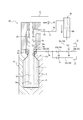
- Such a method of manufacturing a liquid-filled container of the present embodiment can be implemented, for example, using the liquid-filled container manufacturing apparatus 1 configured as shown in FIG.
- the manufacturing apparatus 1 of the liquid containing container shown in FIG. 1 manufactures the liquid containing container C (refer FIG. 4) which accommodated the content liquid from the preform 2 made from a synthetic resin.
- the liquid (content liquid) L contained in the liquid-containing container C various liquids L such as beverages, cosmetics, medicines, detergents, and toiletries such as shampoos can be adopted.
- thermoplastic synthetic resin material such as polypropylene (PP) or polyethylene terephthalate (PET) is connected to the cylindrical opening 2a serving as the opening end and the opening 2a and the lower end is closed. What was formed in the bottomed cylindrical shape which has the cylindrical body part 2b can be used.
- an engagement protrusion for attaching a closing cap (not shown) to the opening 2a of the liquid container C after molding by undercutting engagement is provided.
- a male screw may be provided to attach the closure cap to the opening 2a by screw connection.
- the liquid containing container manufacturing apparatus 1 has a blow molding die 10.
- the blow molding die 10 has a cavity 11 having a shape corresponding to the final shape of the liquid-filled container C, for example, a bottle shape.
- the cavity 11 opens upward on the upper surface of the blow molding die 10.
- the body 2 b is disposed inside the cavity 11 of the blow molding die 10 and the opening 2 a protrudes upward from the blow molding die 10 so that the blow molding die 10 is formed. It is attached to.
- the blow molding die 10 can be opened to the left and right, and after the preform 2 is formed into the liquid-containing container C, the blow molding die 10 is opened to the left and right to obtain the container containing the liquid. C can be taken out from the blow molding die 10.
- a nozzle unit 20 for supplying the pressurized liquid L to the inside of the preform 2 is provided above the blow molding die 10.
- the nozzle unit 20 has a main body block 21.
- a support block 22 is provided at the lower end of the main body block 21, and is supported by the support block 22, and a blow nozzle 23 is mounted at the lower end of the main body block 21.
- the blow nozzle 23 is formed in a substantially cylindrical shape, and the inside of the lower end portion thereof is a liquid supply port 23a.
- the main body block 21, the support block 22, and the blow nozzle 23 constitute a nozzle unit main body 20 a.
- the nozzle unit body 20 a is movable relative to the blow molding die 10 in the vertical direction. When the nozzle unit body 20a is lowered to the lower stroke end, the nozzle unit body 20a (more specifically, the blow nozzle 23) is placed on the opening 2a of the preform 2 attached to the blow molding die 10. Engage sealingly from above.
- the vertical flow path 24 extending to the liquid supply port 23a of the blow nozzle 23 is provided inside the nozzle unit main body 20a (more specifically, the main body block 21 and the blow nozzle 23).
- the vertical flow path 24 extends in the vertical direction.
- the nozzle unit main body 20a (more specifically, the main body block 21) is provided with a supply port 25 communicating with the upper end of the vertical flow path 24.
- the nozzle unit body 20 a (more specifically, the blow nozzle 23) has an annular (annular) seat 24 a provided in the vertical flow passage 24.
- the annular seat 24 a is constituted by the upper surface of the blow nozzle 23.
- the annular seat 24 a may be configured by the inner peripheral surface of the blow nozzle 23 or may be configured by the upper surface and the inner peripheral surface of the blow nozzle 23.
- the annular seat portion 24a is formed of a downward conical tapered surface. However, the shape of the annular seat 24a can be changed as appropriate.
- a seal body 26 for opening and closing (the seat 24 a of) the vertical flow passage 24 is disposed in the vertical flow passage 24.
- the seal body 26 is formed in a cylindrical shape, and the lower end of the seal body 26 is provided with a downward conical tapered surface 26 a.
- the seal surface 26 a abuts on the upper surface (seat portion 24 a) of the blow nozzle 23 and the vertical channel 24 (seat portion 24 a) Block the
- the tapered surface 26 a is provided at the lower end of the seal body 26, but the arrangement can be changed as appropriate.
- the taper surface 26a has a downward conical shape, the shape can be changed as appropriate.
- the seal body 26 moves upward from the closed position, the lower end face of the seal body 26 separates from the upper surface (seat portion 24a) of the blow nozzle 23, and the vertical flow path 24 (seat portion 24a) is opened. Ru.
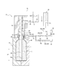
- Seal body 26 has a closed position for closing vertical flow path 24 (seat 24a) and maximum flow, which is the maximum opening in the liquid blow molding process, for vertical flow path 24 (seat 24a) It is movable between an open position where it is opened. More specifically, the seal body 26 is movable between a closed position (see FIG. 1), a preliminary open position (see FIG. 2), and an open position (see FIG. 4). In the preliminary opening position, the opening degree of the seal body 26 which opens and closes the vertical flow path 24 (seat portion 24a) is smaller than the opening degree in the opening position.
- the effective cross-sectional area of the longitudinal flow passage 24 in the pre-opening position is 10% or less of the effective cross-sectional area of the longitudinal flow passage 24 in the open position.
- the seal body 26 is fixed to a shaft body 27 provided so as to be movable relative to the nozzle unit main body 20a in the vertical direction, and movable in the vertical direction within the vertical flow path 24. It has become.
- the seal body 26 may be formed integrally with the shaft body 27.
- the nozzle unit 20 has a discharge rod 28 provided with a discharge port 28a.
- the discharge rod 28 formed in a substantially cylindrical shape by steel or the like extends along the axial center of the shaft 27 and the seal 26.
- the discharge rod 28 can be driven by a drive source (not shown) to move in the vertical direction relative to the shaft 27 and the seal 26.
- the discharge port 28a is in communication with the first pipe P1 via a hollow portion (not shown) of the discharge rod 28. More specifically, the lower end portion of the hollow portion of the discharge rod 28 is in communication with the discharge port 28a, and the upper end portion of the hollow portion of the discharge rod 28 is in communication with the first pipe P1.
- the rod valve V1 is provided in the first pipe P1, and the rod pipe V1 can open and close the first pipe P1.
- the rod valve V1 is preferably configured by an electromagnetic valve that can be controlled by the control device.
- the lower end of the discharge rod 28 is closed, and the discharge port 28 a is provided on the peripheral wall of the discharge rod 28. Therefore, when the discharge rod 28 is pulled back to the original position after the formation of the head space HS (see FIG. 7) of the container C, dripping does not easily occur.
- the present invention is not limited to such a configuration, and the discharge port 28a may be provided on the lower end surface of the discharge rod 28, or may be provided on both the lower end surface and the peripheral wall.
- the discharge rod 28 may be used as a drawing rod as in the present embodiment.
- the discharge rod 28 can extend the preform 2 in the axial direction by moving downward.
- the flow path 29 through which the liquid L and / or the gas (air in the present embodiment) flows is provided.
- the flow path 29 is a portion on the downstream side of the seat portion 24 a (in the present embodiment, the blow nozzle 23) in a supply path described later (the supply path includes the third pipe P 3, the supply port 25 and the vertical flow path 24).
- the suction state in which the opening 31 provided on the inner circumferential surface is connected to the suction source 32 capable of suctioning the liquid L in the flow path 29, and the gas (air in this embodiment) pressurized in the opening 31 is supplied.
- Possible pressurized gas supply source 33 open air state where the opening 31 is connected to the atmosphere, and shut off the opening 31 to any of the suction source 32, the pressurized gas supply source 33 and the atmosphere
- the closed state can be selected alternatively.
- by setting the flow path 29 in a suction state liquid dripping from the blow nozzle 23 can be prevented. It is not necessary to make the flow path 29 in a suction state when the content is a liquid which hardly causes liquid dripping or when liquid dripping may occur (a configuration in which the third path 29c and the suction source 32 are not provided) May be As shown in FIG.
- the discharge of the liquid L can be promoted or assisted by supplying pressurized gas (air) inside.
- the suction source 32 can be configured by, for example, a suction pump or the like.
- the pressurized gas supply source 33 can be configured by, for example, a pressure pump or the like.
- the suction source 32 and the pressurized gas supply source 33 may be configured by a suction / pressure pump (for example, a plunger pump such as the pressurized liquid supply source 30) in which the suction pump and the pressure pump are integrated.
- the flow path 29 can be provided partially or entirely in (the nozzle unit main body 20 a of) the nozzle unit 20.
- the flow path 29 includes a first path 29a provided with a first valve Va, a second path 29b provided with a second valve Vb, and a third valve Vc. It has a third path 29c provided, a fourth path 29d provided with a fourth valve Vd, and a fifth path 29e provided with a fifth valve Ve.
- One end of the first path 29 a is connected to the opening 31, and the other end is connected to the first branch 34.
- One end of the second path 29b is connected to the second branch 35, and the other end is open to the atmosphere.
- One end of the third path 29 c is connected to the second branch 35 and the other end is connected to the suction source 32.
- One end of the fourth path 29 d is connected to the first branch 34, and the other end is connected to the second branch 35.
- One end of the fifth path 29 e is connected to the first branch 34, and the other end is connected to the pressurized gas supply source 33.
- the first to fifth valves Va to Ve are preferably configured by solenoid valves.
- the pressurized liquid supply source 30 is connected to the supply port 25 by the second pipe P2.
- the pressurized liquid supply source 30 can be configured by, for example, a plunger pump provided with a cylinder 30a and a piston (plunger) 30b.
- the pressurized liquid supply source 30 has the blow nozzle 23 engaged in a sealed state with the opening 2 a of the preform 2 mounted on the blow molding die 10 and the seal body 26.
- the pressurized liquid L can be supplied to the inside of the preform 2 through the port 23a).
- the second pipe P2 branches into a first pipe P1 and a third pipe P3 at a branch portion S.
- the nozzle unit 20 has a common path formed of a second pipe P2 extending from the pressurized liquid supply source 30 to the branch S, a third pipe P3 extending from the branch S to the supply port 25, a supply port 25 and a vertical flow path A discharge path (including a first pipe P1) extending from the branch portion S to the discharge port 28a provided in the discharge rod 28 is provided.
- the pressurized liquid supply source 30 operates in the reverse direction with the seal 26 closing the vertical flow passage 24 and the rod valve V1 being opened, whereby the discharge port 28a of the discharge rod 28 is opened.
- the liquid L can be discharged from the inside of the liquid-filled container C into the discharge path from the discharge port 28 a to the branch portion S through the
- the seal body 26 closes the vertical flow passage 24, and the rod valve V1 operates in the reverse direction in the closed state, whereby the liquid L stored in the supply tank (not shown) is moved to the cylinder 30a. Can be aspirated into the interior of the and ready for the next liquid blow molding.
- a control device not shown.
- a liquid-containing container C in which a liquid (content liquid) L is accommodated inside a container having a predetermined shape from a preform 2 made of synthetic resin is obtained.
- a method of forming (a method of manufacturing a liquid-filled container according to the present embodiment) will be described.
- a waiting process is performed.
- a predetermined temperature for example, 80 ° C. to 150 ° C.
- heating means such as a heater Attach to mold 10 and clamp.
- the nozzle unit 20 is at a position separated upward with respect to the blow molding die 10, and the seal body 26 closes the seat 24a. Also, the flow path 29 is in a suction state. More specifically, the first valve Va is open, the second valve Vb is closed, the third valve Vc is open, the fourth valve Vd is open, and the fifth valve Ve is closed. At this time, since the opening 2a of the preform 2 is open, the inside of the preform 2 is filled with air.
- an air discharging step is performed.
- the seal unit is lowered with the nozzle unit 20 lowered to engage the blow nozzle 23 with the opening 2a of the preform 2 and the flow passage 29 is open to the atmosphere.
- 26 is moved to the pre-opening position, and the plunger 30b is operated in the positive direction at the first speed (that is, at the first pressure) to supply the liquid L to the inside of the preform 2 from the vertical flow path 24 (supply path).
- the air inside the preform 2 is exhausted to the atmosphere (outside) through the flow path 29.
- the first valve Va is opened, the second valve Vb is opened, the third valve Vc is closed, the fourth valve Vd is opened, and the fifth valve Ve is closed.
- a liquid blow molding step is then performed.
- the pressurized liquid supply source 30 applies pressure to the inside of the preform 2 from the vertical flow path 24 (supply path).
- the preform 2 is formed into a liquid-filled container C having a shape along the cavity 11 of the blow molding die 10.
- a rod purge step is first performed at the beginning of the liquid blow molding step.
- the rod purge step first, the flow path 29 is closed, the rod valve V1 is opened, and then the plunger 30b is moved at a second speed higher than the first speed while keeping the seal 26 in the pre-opening position That is, by operating in the forward direction with a second pressure higher than the first pressure, the discharge port 28a of the discharge rod 28 in the liquid L inside the preform 2 before and / or during the formation into the liquid-containing container C.
- Discharge the liquid L from the In the present embodiment all of the first to fifth valves Va to Ve are closed in the rod purge step and the liquid blow molding step.
- the third valve Vc may be opened in advance in preparation for the rod raising and depressurizing process.
- the fifth valve Ve may be opened in advance in preparation for the second stage suck back in the head space forming process.
- Some air may be mixed into the liquid L discharged from the discharge port 28 a of the discharge rod 28 in the previous head space forming step due to the process of the vertical movement of the discharge rod 28 or the like.
- the stability of the forming conditions pressure of the liquid L during the liquid blow molding, etc.
- the deterioration of the formability of the container are caused. There is a risk. If the liquid L (preferably the entire amount) discharged from the discharge port 28a of the discharge rod 28 in the previous head space forming step is discharged into the inside of the preform 2 by the above-described rod purge step, air is accumulated in this manner. Can be prevented.
- the amount of air supplied to the inside of the preform 2 is small, so the influence on the formability can be ignored.
- the discharge of the liquid L from the discharge port 28 a is performed in the liquid L inside the preform 2. Therefore, the occurrence of bubbling inside the preform 2 can be suppressed.
- the rod purge step is performed by operating the plunger 30b in the positive direction at the second speed while keeping the seal body 26 in the preliminary open position, but the seal body 26 is moved to the open position
- the plunger 30b may be operated in the positive direction at the second speed.
- the seal body 26 is moved to the closed position and then the rod valve V1 is opened to operate the plunger 30b in the forward direction (for example, , Second speed) is preferable.
- an open / close valve is provided on the third pipe P3 and the open / close valve is closed and the rod valve V1 is opened (at this time, the seal body 26 may be kept in the preliminary open position or may be moved to the open position) And the plunger 30b may be operated in a positive direction (eg, a second speed).
- the seal body 26 is then raised from the pre-opening position to the open position while the plunger 30b is operated in the positive direction at the second speed.
- the liquid L pressurized to the second pressure is supplied to the inside of the preform 2 from the passage 24 (supply passage) through the seat portion 24a.
- the preform 2 is formed into a liquid-filled container C having a shape along the cavity 11 of the blow molding die 10.
- the liquid blow molding step is performed in a state in which most of the air inside the preform 2 is discharged to the outside in the air discharging step, when the pressurized liquid L is supplied to the inside of the preform 2 In addition, the liquid L does not entrap air, whereby the mixing of the air into the liquid L in the liquid-containing container C is suppressed.
- the rod drawing step is performed during the liquid blow molding step.
- the rod stretching step the body portion 2b of the preform 2 is stretched in the axial direction (longitudinal direction) by the stretching rod 28 which advances downward.
- the rod drawing step may be performed prior to the liquid blow molding step.
- the preform 2 is axially drawn by the drawing rod 28. Since it is possible to perform biaxial stretch blow molding in which blow molding is performed, the preform 2 can be formed into a liquid-containing container C having a predetermined shape more accurately.
- the liquid blow molding step may be performed without the rod drawing step.
- FIG. 1 shows the drawing rod 28 in the original position.
- the lower end surface of the extension rod 28 does not have to be located at the height shown in FIG. 1 in the original position, but may be located above or below the height.
- a head space forming process is then performed.
- the first stage suck back is performed in the head space forming step (that is, liquid is supplied through the supply path by operating the pressurized liquid supply source 30 in the suction direction).
- the liquid L is discharged from the inside of the container C).
- the first stage suck back as shown in FIG.
- the seal body 26 is in the open position, the flow path 29 is in the closed state, and the rod valve V1 is kept open (the rod valve V1 may be closed)
- the plunger 30b is actuated in the reverse direction (suction direction) by a predetermined actuation amount to suck back a predetermined amount of liquid L from the inside of the container C containing liquid after molding to the vertical flow passage 24 (supply passage).
- the positive pressure state inside the container C is canceled (a negative pressure state may be made), and then the liquid L from the inside of the container C when the flow path 29 is pressurized. Can be suppressed from entering the flow path 29.
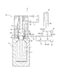
- the seal body 26 in the head space forming step, when the first stage suck back is completed, the seal body 26 is moved to the closed position (see FIG. 6), the flow path 29 is pressurized, and the second stage is performed. Suck back (see FIG. 7). More specifically, as shown in FIG. 7, the flow path 29 opens the first valve Va, closes the second valve Vb, closes the third valve Vc, closes the fourth valve Vd, and closes the fifth valve Ve. Is open. However, the third valve Vc may be opened in advance in preparation for the rod raising and depressurizing process.
- the rod valve V1 In the second stage suck back, the rod valve V1 is opened, and the pressurized liquid supply source 30 (the plunger 30b thereof) is actuated in the suction direction with the vertical flow path 24 (supply path) closed.
- the liquid L is discharged from the inside of the liquid-filled container C through the discharge port 28 a provided in the discharge rod 28 extending to the inside of the liquid-filled container C through the blow nozzle 23, and the head space HS is formed in the liquid-filled container C.
- the second stage suck back since the second stage suck back is performed while supplying pressurized gas from the flow path 29 to the inside of the preform 2, discharge of the liquid L through the discharge port 28a is promoted. .
- the support by the pressurized gas is particularly effective when the viscosity of the liquid L used as the content liquid is large.
- the flow path 29 is opened to the atmosphere (or The blow nozzle 23 may be detached from the opening 2a of the container C so that the atmosphere can be introduced from the outside), and the second stage suck back may be performed.
- the flow path 29 is closed, and the inside of the container C is made negative pressure by the second stage suckback.
- the flow passage 29 may be opened to the atmosphere to form the head space HS.
- the second stage suckback may be performed simultaneously with the first stage suckback (including partial overlap due to a time difference).
- the liquid L is discharged through the discharge port 28a only by the pressurized gas from the flow path 29 (that is, the pressurized liquid supply source 30 is
- the liquid L is discharged from the inside of the liquid filled container C through the discharge port 28a of the discharge rod 28 by introducing a pressurized gas into the liquid filled container C without operating in the suction direction), the head space HS It may be formed.
- the discharge port 28a located in the lower half portion LP (the lower portion when the height is equally divided into two in the vertical direction) of the liquid-containing container C with little air contamination.
- the liquid L is discharged from the inside of the container C containing liquid.
- the liquid L may be discharged from the inside of the liquid containing container C through the discharge port 28 a located in the upper half of the liquid containing container C.
- the discharge rod 28 may be provided with a plurality of discharge ports 28 a along the axial direction and / or the circumferential direction. The arrangement position, the number, the shape and the like of the discharge port 28a can be appropriately set in accordance with the type and the property of the liquid L and the like.
- the amount of the liquid L discharged from the inside of the liquid filled container C through the discharge port 28a is equal to or less than the internal volume of the discharge path. Therefore, it can be prevented that the discharged liquid L is mixed with the air in the supply path (the vertical flow path 24, the supply port 25 and the third pipe P3). From this point of view, the amount of the liquid L discharged from the inside of the liquid-filled container C through the discharge port 28a in the head space forming step is preferably equal to or less than the internal volume from the discharge port 28a to the rod valve V1 in the discharge path.
- the pressurized liquid supply source 30 for pressurizing the supply path can also be used for the discharge, and the configuration of the nozzle unit 20 can be simplified.
- the amount of the liquid L discharged from the inside of the liquid filled container C through the discharge port 28a in the head space forming step may be larger than the internal volume of the discharge path.
- the rod lifting and depressurizing process is performed.
- the discharge rod (stretching rod) 28 is raised and returned to the original position. Further, the flow passage 29 is brought into a suction state, and the rod valve V1 is closed. Then, the nozzle unit 20 is raised, and the container C containing liquid is taken out from the blow molding die 10. Then, the pressurized liquid supply source 30 is filled, and the process proceeds to the standby process shown in FIG.
- the method of manufacturing the liquid-filled container of the present invention is performed using the manufacturing apparatus 1 of the liquid-filled container having the configuration shown in FIG. Can also be used to carry out the method for producing a liquid-filled container of the present invention.
- the first stage suckback is performed.
- the first stage suck back may not be performed.
- the air is prevented from accumulating in the vertical flow path 24 (supply path), thereby suppressing the deterioration of the stability of the molding conditions and the moldability of the container. can do.
- the inside of the preform 2 is opened to the atmosphere by bringing the flow passage 29 into the atmosphere open state with the blow nozzle 23 engaged with the opening 2 a of the preform 2 in the air discharging step.
- the blow nozzle 23 may not be engaged with the opening 2 a of the preform 2 to secure a discharge passage of air from the inside to the outside of the preform 2.
- the pressurized liquid supply source 30 is a plunger pump
- the invention is not limited thereto, and the liquid L can be pressurized to a predetermined pressure and supplied to the preform 2
- Various types of pumps such as other types of pumps can be used as long as they can generate a negative pressure for the suckback of L.
- the liquid L is discharged from the discharge port 28 a of the discharge rod 28 in the liquid L in the preform 2 before and / or during the formation into the liquid-containing container C. It was done, but it is not limited to this.
- the discharge of the liquid L from the discharge port 28a of the discharge rod 28 may always be performed in air.
- the discharge of the liquid L from the discharge port 28a is always performed in the liquid L inside the preform 2.
- the initial stage of the discharge is air It may be carried out in the liquid L after that.
- a step of supplying the liquid L to the inside of the preform 2 in advance by means other than the blow nozzle 23 may be provided prior to the rod purge step (for example, before the standby step).
- the rod purge process was performed in the middle of the liquid blow molding process, it is not restricted to this.
- the rod purge step may be performed before the liquid blow molding step (e.g., before or during the air discharging step, or between the air discharging step and the liquid blow molding step).
- the discharge of the liquid L from the discharge port 28a of the discharge rod 28 may be performed in the liquid L inside the liquid filled container C immediately after molding (before the first stage suckback) depending on the conditions. You may go.
- the rod purge step may not be performed.
- the air discharging step is performed in the above embodiment, the air discharging step may not be performed.
- preform 2 those having various shapes can be used according to the shape of the container C containing the liquid after molding.
Landscapes
- Engineering & Computer Science (AREA)
- Manufacturing & Machinery (AREA)
- Mechanical Engineering (AREA)
- Blow-Moulding Or Thermoforming Of Plastics Or The Like (AREA)
Abstract
ブローノズル(23)をプリフォーム(2)の口部(2a)に係合させた状態で供給路からプリフォーム(2)の内部に加圧した液体(L)を供給することにより、プリフォーム(2)をブロー成形用金型(10)の内面に沿った形状の液体入り容器(C)に成形する液体ブロー成形工程と、加圧液体供給源(30)を吸引方向に作動させることによって供給路を通して液体入り容器(C)の内部から液体(L)を排出した後に供給路を閉塞し、ブローノズル(23)を通して液体入り容器(C)の内部まで延びた排出ロッド(28)に設けられた排出口(28a)を通して、液体入り容器(C)の内部から液体(L)を排出することにより、液体入り容器(C)にヘッドスペース(HS)を形成するヘッドスペース形成工程とを有する、液体入り容器の製造方法。
Description
本発明は、合成樹脂製のプリフォームから内容液を収容した液体入り容器を製造する液体入り容器の製造方法に関する。
ポリプロピレン(PP)製のボトルやポリエチレンテレフタレート(PET)製のボトルに代表されるような合成樹脂製の容器は、飲料、化粧品、薬品、洗剤、シャンプー等のトイレタリーなどの様々な液体を内容液として収容する用途に使用されている。このような容器は、上記したような熱可塑性を有する合成樹脂材料によって形成されたプリフォームをブロー成形することにより製造されるのが一般的である。
プリフォームを容器に成形するブロー成形としては、プリフォームの内部に供給する加圧媒体として、加圧エアーに替えて加圧した液体を用いるようにした液体ブロー成形が知られている。
例えば特許文献1には、予め延伸性を発現する温度にまで加熱しておいた合成樹脂製のプリフォームをブロー成形用金型に装着し、このプリフォームの内部にブローノズルを通してポンプ等の加圧手段により所定圧力にまで加圧した液体を供給することにより、当該プリフォームをブロー成形用金型のキャビティに沿った所定形状の容器に成形するようにした液体ブロー成形方法が記載されている。
上記のような液体ブロー成形方法では、プリフォームに供給する液体として最終的に製品として容器に収容される内容液を使用することにより、容器の成形と当該容器への内容液の充填とを同時に行って、内容液を収容した液体入り容器を製造することができる。したがって、このように液体ブロー成形を利用した液体入り容器の製造方法によれば、成形後の容器への内容液の充填工程を省略して、液体入り容器を低コストで製造することができる。
上記従来の液体ブロー成形方法では、通常、成形後の容器に所望の大きさのヘッドスペースを形成することが求められる。ヘッドスペースを形成する方法としては、例えば、液体入り容器の成形直後にポンプによりブローノズルを介して容器の内部の液体を吸引し、容器の内部を負圧化した後に容器の内部を大気開放して、容器の内部に空気を導入することでヘッドスペースを形成することが考えられる。しかし、成形直後の容器の内部に存在する液体は、プリフォームの内部に存在していた空気を巻き込んで泡立った状態になっている。したがって、上記のような方法では、この泡立った液体をブローノズルに通じる液体の供給路に導入することになるので、当該供給路に空気が混入し、成形条件の安定性や容器の成形性等が低下するという問題が生じる虞がある。
本発明は、このような課題に鑑みてなされたものであり、その目的は、液体入り容器を所定の内容量及び形状を有するように精度よく且つ低コストで製造することができる液体入り容器の製造方法を提供することにある。
本発明の液体入り容器の製造方法は、ノズルユニットとブロー成形用金型とを用いて合成樹脂製のプリフォームから内容液を収容した液体入り容器を製造する液体入り容器の製造方法であって、前記ノズルユニットは、加圧液体供給源から分岐部まで延びる液体の共通経路と、前記分岐部からブローノズルまで延びる液体の供給路と、前記分岐部から排出ロッドに設けられた排出口まで延びる液体の排出経路とを有し、前記ブローノズルを前記プリフォームの口部に係合させた状態で前記供給路から前記プリフォームの内部に前記加圧液体供給源によって加圧した液体を供給することにより、前記プリフォームを前記ブロー成形用金型の内面に沿った形状の前記液体入り容器に成形する液体ブロー成形工程と、前記加圧液体供給源を吸引方向に作動させることによって前記供給路を通して前記液体入り容器の内部から液体を排出した後に前記供給路を閉塞し、前記ブローノズルを通して前記液体入り容器の内部まで延びた前記排出ロッドに設けられた前記排出口を通して、前記液体入り容器の内部から液体を排出することにより、前記液体入り容器にヘッドスペースを形成するヘッドスペース形成工程とを有するものである。
本発明の液体入り容器の製造方法は、上記構成において、前記ヘッドスペース形成工程において、前記加圧液体供給源を吸引方向に作動させることにより、前記排出ロッドの前記排出口を通して前記液体入り容器の内部から液体を排出するのが好ましい。
本発明の液体入り容器の製造方法は、上記構成において、前記ヘッドスペース形成工程において、前記液体入り容器の内部に加圧した気体を導入することにより、前記排出ロッドの前記排出口を通して前記液体入り容器の内部から液体を排出するのが好ましい。
本発明の液体入り容器の製造方法は、上記構成において、前記液体入り容器への成形前及び/又は成形途中の前記プリフォームの内部の液体中で、前記排出ロッドの前記排出口から液体を吐出するロッドパージ工程をさらに有するのが好ましい。
本発明の液体入り容器の製造方法は、上記構成において、前記ロッドパージ工程において、前回行った前記ヘッドスペース形成工程において前記排出口を通して前記液体入り容器の内部から排出した液体の全量を前記排出口から吐出するのが好ましい。
本発明の液体入り容器の製造方法は、上記構成において、前記ロッドパージ工程において、液体中で、前記排出ロッドの前記排出口から液体を吐出するのが好ましい。
本発明の液体入り容器の製造方法は、上記構成において、前記液体ブロー成形工程より前に前記プリフォームの内部に液体を供給することにより、前記プリフォームの内部の空気を外部に排出させる空気排出工程をさらに有するのが好ましい。
本発明の液体入り容器の製造方法は、上記構成において、前記ヘッドスペース形成工程において前記排出口を通して前記液体入り容器の内部から排出する液体の量は、前記排出経路の内部体積以下であるのが好ましい。
本発明の液体入り容器の製造方法は、上記構成において、前記液体ブロー成形工程の最中又は前記液体ブロー成形工程より前に延伸ロッドにより前記プリフォームを軸方向に延伸させるロッド延伸工程をさらに有し、前記排出ロッドは前記延伸ロッドであるのが好ましい。
本発明によれば、液体入り容器を所定の内容量及び形状を有するように精度よく且つ低コストで製造することができる液体入り容器の製造方法を提供することができる。
以下、図面を参照して本発明をより具体的に例示説明する。
本発明の一実施形態である液体入り容器の製造方法は、ノズルユニットとブロー成形用金型とを用いて合成樹脂製のプリフォームから内容液を収容した液体入り容器を製造する液体入り容器の製造方法であって、ノズルユニットは、加圧液体供給源から分岐部まで延びる液体の共通経路と、分岐部からブローノズルまで延びる液体の供給路と、分岐部から排出ロッドに設けられた排出口まで延びる液体の排出経路とを有し、ブローノズルをプリフォームの口部に係合させた状態で供給路からプリフォームの内部に加圧液体供給源によって加圧した液体を供給することにより、プリフォームをブロー成形用金型の内面に沿った形状の液体入り容器に成形する液体ブロー成形工程と、前記加圧液体供給源を吸引方向に作動させることによって前記供給路を通して前記液体入り容器の内部から液体を排出した後に供給路を閉塞し、ブローノズルを通して液体入り容器の内部まで延びた排出ロッドに設けられた排出口を通して、液体入り容器の内部から液体を排出することにより、液体入り容器にヘッドスペースを形成するヘッドスペース形成工程とを有する、液体入り容器の製造方法である。
本実施形態の液体入り容器の製造方法は、ヘッドスペース形成工程において、加圧液体供給源を吸引方向に作動させることにより、排出ロッドの排出口を通して液体入り容器の内部から液体を排出するようにしている。
本実施形態の液体入り容器の製造方法は、ヘッドスペース形成工程において、液体入り容器の内部に加圧した気体を導入することにより、排出ロッドの排出口を通して液体入り容器の内部から液体を排出するようにしている。
本実施形態の液体入り容器の製造方法は、液体入り容器への成形前及び/又は成形途中のプリフォームの内部の液体中で、排出ロッドの排出口から液体を吐出するロッドパージ工程をさらに有している。
本実施形態の液体入り容器の製造方法は、ロッドパージ工程において、前回行ったヘッドスペース形成工程において排出口を通して液体入り容器の内部から排出した液体の全量を排出口から吐出するようにしている。
本実施形態の液体入り容器の製造方法は、ロッドパージ工程において、液体中で、排出ロッドの排出口から液体を吐出するようにしている。
本実施形態の液体入り容器の製造方法は、液体ブロー成形工程より前にプリフォームの内部に液体を供給することにより、プリフォームの内部の空気を外部に排出させる空気排出工程をさらに有している。
本実施形態の液体入り容器の製造方法では、ヘッドスペース形成工程において排出口を通して液体入り容器の内部から排出する液体の量は、排出経路の内部体積以下である。
本実施形態の液体入り容器の製造方法は、液体ブロー成形工程の最中に延伸ロッドによりプリフォームを軸方向に延伸させるロッド延伸工程をさらに有し、排出ロッドは延伸ロッドである。
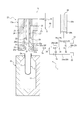
このような本実施形態の液体入り容器の製造方法は、例えば図1に示す構成の液体入り容器の製造装置1を用いて実施することができる。
図1に示す液体入り容器の製造装置1は、合成樹脂製のプリフォーム2から内容液を収容した液体入り容器C(図4参照)を製造するものである。液体入り容器Cに収容される液体(内容液)Lとしては、例えば飲料、化粧品、薬品、洗剤、シャンプー等のトイレタリーなどの様々な液体Lを採用することができる。
プリフォーム2としては、例えばポリプロピレン(PP)やポリエチレンテレフタレート(PET)等の熱可塑性を有する合成樹脂材料によって、開口端となる円筒状の口部2aと、口部2aに連なるとともに下端が閉塞された円筒状の胴部2bとを有する有底筒状に形成されたものを用いることができる。
詳細は図示しないが、口部2aの外壁面には、成形後の液体入り容器Cの口部2aに閉塞キャップ(不図示)を打栓(アンダーカット係合)によって装着するための係合突起が設けられている。なお、口部2aの外壁面に係合突起に替えて雄ネジを設けて閉塞キャップを口部2aにねじ結合により装着する構成とすることもできる。
液体入り容器の製造装置1は、ブロー成形用金型10を有している。ブロー成形用金型10は、例えばボトル形状などの液体入り容器Cの最終形状に対応した形状のキャビティ11を有している。キャビティ11はブロー成形用金型10の上面において上方に向けて開口している。プリフォーム2は、胴部2bがブロー成形用金型10のキャビティ11の内部に配置されるとともに口部2aがブロー成形用金型10から上方に突出した状態となってブロー成形用金型10に装着される。
ブロー成形用金型10は左右に型開きすることができるようになっており、プリフォーム2を液体入り容器Cに成形した後にブロー成形用金型10を左右に開くことで、当該液体入り容器Cをブロー成形用金型10から取り出すことができるようになっている。
ブロー成形用金型10の上方には、プリフォーム2の内部に加圧した液体Lを供給するためのノズルユニット20が設けられている。ノズルユニット20は本体ブロック21を有している。
本体ブロック21の下端には支持ブロック22が設けられ、この支持ブロック22により支持されて本体ブロック21の下端にはブローノズル23が装着されている。ブローノズル23は略円筒状に形成されており、その下端部の内側は液体供給口23aとなっている。本体ブロック21、支持ブロック22及びブローノズル23によって、ノズルユニット本体20aが構成されている。ノズルユニット本体20aはブロー成形用金型10に対して上下方向に相対移動自在となっている。ノズルユニット本体20aが下方側のストローク端にまで下降すると、ノズルユニット本体20a(より具体的には、ブローノズル23)は、ブロー成形用金型10に装着されたプリフォーム2の口部2aに上方側から密封状態で係合する。
ノズルユニット本体20a(より具体的には、本体ブロック21及びブローノズル23)の内部には、ブローノズル23の液体供給口23aまで延びる縦流路24が設けられている。この縦流路24は上下方向に延びている。
ノズルユニット本体20a(より具体的には、本体ブロック21)には、縦流路24の上端に連通する供給ポート25が設けられている。
ノズルユニット本体20a(より具体的には、ブローノズル23)は、縦流路24に設けられた環状(円環状)の座部24aを有している。環状の座部24aは、ブローノズル23の上面によって構成されている。環状の座部24aは、ブローノズル23の内周面によって構成してもよいし、ブローノズル23の上面及び内周面によって構成してもよい。環状の座部24aは、下向き円錐状のテーパ面からなっている。しかし、環状の座部24aの形状は適宜変更が可能である。縦流路24の内部には、縦流路24(の座部24a)を開閉するためのシール体26が配置されている。シール体26は円筒状に形成されており、シール体26の下端には、下向き円錐状のテーパ面26aが設けられている。シール体26は、下方側のストローク端位置である閉塞位置にまで移動したときに、テーパ面26aにおいてブローノズル23の上面(座部24a)に当接して縦流路24(の座部24a)を閉塞する。テーパ面26aはシール体26の下端に設けられているが、その配置は適宜変更が可能である。また、テーパ面26aは下向き円錐状をなしているが、その形状は適宜変更が可能である。一方、シール体26が閉塞位置から上方に向けて移動すると、シール体26の下端面がブローノズル23の上面(座部24a)から離脱して縦流路24(の座部24a)が開放される。
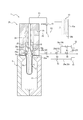
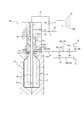
シール体26は、縦流路24(の座部24a)を閉塞する閉塞位置と、縦流路24(の座部24a)を、液体ブロー成形工程内で最大となる開度である最大開度で開放する開放位置との間で移動可能である。より具体的には、シール体26は、閉塞位置(図1参照)と、予備開放位置(図2参照)と、開放位置(図4参照)との間で移動可能となっている。予備開放位置では、縦流路24(の座部24a)を開閉するシール体26の開度は、開放位置での開度よりも小さくなっている。好ましくは、予備開放位置での縦流路24の有効断面積は、開放位置での縦流路24の有効断面積の10%以下とする。図1に示すように、シール体26はノズルユニット本体20aに対して相対的に上下方向に移動自在に設けられた軸体27に固定され、縦流路24の内部で上下方向に移動自在となっている。なお、シール体26は、軸体27と一体に形成してもよい。
ノズルユニット20は、排出口28aが設けられた排出ロッド28を有している。鋼材等によって略円柱状に形成された排出ロッド28は、軸体27及びシール体26の軸心に沿って延びている。排出ロッド28は、図示しない駆動源により駆動されて軸体27及びシール体26に対して相対的に上下方向に移動することができる。排出口28aは、排出ロッド28の中空部(図示省略)を介して第1配管P1に連通している。より具体的には、排出ロッド28の中空部の下端部が排出口28aに連通し、排出ロッド28の中空部の上端部が第1配管P1に連通している。第1配管P1には、ロッドバルブV1が設けられ、このロッドバルブV1により第1配管P1を開閉することができる。なお、ロッドバルブV1は、制御装置によって制御可能な電磁弁により構成されるのが好ましい。本実施形態では、排出ロッド28の下端が閉塞されており、排出口28aは排出ロッド28の周壁に設けられている。したがって、容器CのヘッドスペースHS(図7参照)の形成後に排出ロッド28を原位置に引き戻す際に、液垂れが生じ難い。しかし、このような構成に限定されず、排出口28aは、排出ロッド28の下端面に設けても、下端面と周壁との両方に設けてもよい。
排出ロッド28は、本実施形態のように、延伸ロッドとして用いてもよい。排出ロッド28は、下方に向けて移動することにより、プリフォーム2を軸方向に延伸させることができる。
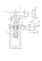
ノズルユニット20(のノズルユニット本体20a)の内部には、液体L及び/又は気体(本実施形態では空気)が流れる流路29が設けられている。流路29は、後述する供給路(供給路は、第3配管P3、供給ポート25及び縦流路24で構成される)における座部24aより下流側の部分(本実施形態ではブローノズル23の内周面)に設けられた開口31を、流路29内の液体Lを吸引可能な吸引源32に接続した吸引状態と、開口31を、加圧した気体(本実施形態では空気)を供給可能な加圧気体供給源33に接続した加圧状態と、開口31を大気に接続した大気開放状態と、開口31を吸引源32、加圧気体供給源33及び大気のいずれに対しても遮断した閉状態とを択一的に選択可能に構成されている。図1及び図8に示すように、流路29を吸引状態とすることで、ブローノズル23からの液だれを防止することができる。内容物が液だれを生じ難い液体である場合や液だれを生じても構わない場合などにおいては、流路29を吸引状態にする必要はない(第3経路29c及び吸引源32を設けない構成としてもよい)。図2に示すように、流路29を大気開放状態とすることで、空気排出工程において、プリフォーム2の内部から空気を流路29を通して大気(外部)に排出することができる。条件によっては、空気排出工程において、経路29を大気開放状態とする代わりに吸引状態とし、プリフォーム2の内部から空気を排出してもよい。図3及び図4に示すように、流路29を閉状態とすることで、液体ブロー成形工程において、プリフォーム2の内部に加圧した液体Lを安定して供給することができる。図7に示すように、流路29を加圧状態とすることで、ヘッドスペース形成工程においてプリフォーム2の内部から排出ロッド28の排出口28aを通して液体Lを排出するときに、プリフォーム2の内部に加圧した気体(空気)を供給することによって液体Lの排出を促進又は支援することができる。吸引源32は、例えば吸引ポンプ等で構成することができる。加圧気体供給源33は、例えば加圧ポンプ等で構成することができる。吸引源32及び加圧気体供給源33は、吸引ポンプと加圧ポンプを一体型とした吸引・加圧ポンプ(例えば、加圧液体供給源30のようなプランジャーポンプ)で構成してもよい。流路29は、その一部又は全体をノズルユニット20(のノズルユニット本体20a)の内部に設けることができる。
本実施形態では、流路29は、図1に示すように、第1バルブVaが設けられた第1経路29aと、第2バルブVbが設けられた第2経路29bと、第3バルブVcが設けられた第3経路29cと、第4バルブVdが設けられた第4経路29dと、第5バルブVeが設けられた第5経路29eとを有している。第1経路29aの一端は開口31に接続し、他端は第1分岐部34に接続している。第2経路29bの一端は第2分岐部35に接続し、他端は大気に開放されている。第3経路29cの一端は第2分岐部35に接続し、他端は吸引源32に接続している。第4経路29dの一端は第1分岐部34に接続し、他端は第2分岐部35に接続している。第5経路29eの一端は第1分岐部34に接続し、他端は加圧気体供給源33に接続している。第1~第5バルブVa~Veは、電磁弁により構成されるのが好ましい。
供給ポート25には、第2配管P2により加圧液体供給源30が接続されている。加圧液体供給源30は、例えばシリンダ30aとピストン(プランジャー)30bとを備えたプランジャーポンプで構成することができる。
加圧液体供給源30は、図3及び図4に示すように、ブロー成形用金型10に装着されたプリフォーム2の口部2aにブローノズル23が密封状態で係合するとともにシール体26が縦流路24を開放した状態において、正方向(加圧方向)に作動することにより、第2配管P2、第3配管P3、供給ポート25及び縦流路24(の座部24a及び液体供給口23a)を介してプリフォーム2の内部に加圧した液体Lを供給することができる。第2配管P2は、分岐部Sで第1配管P1と第3配管P3とに分岐している。ノズルユニット20は、加圧液体供給源30から分岐部Sまで延びる第2配管P2で構成される共通経路と、分岐部Sから供給ポート25まで延びる第3配管P3、供給ポート25及び縦流路24で構成される供給路と、分岐部Sから排出ロッド28に設けられた排出口28aまで延びる排出経路(第1配管P1を含む)とを有している。
加圧液体供給源30は、図7に示すように、シール体26が縦流路24を閉塞し、ロッドバルブV1が開いた状態において逆方向に作動することにより、排出ロッド28の排出口28aを通して、液体入り容器Cの内部から液体Lを排出口28aから分岐部Sまでの排出経路内に排出することができる。
加圧液体供給源30は、シール体26が縦流路24を閉塞し、ロッドバルブV1が閉じた状態において逆方向に作動することにより、図示しない供給タンクに収容されている液体Lをシリンダ30aの内部に吸引し、次の液体ブロー成形に備えることができる。
ノズルユニット本体20a、シール体26、排出ロッド(延伸ロッド)28、加圧液体供給源30(プランジャー30b)、ロッドバルブV1、第1~第5バルブVa~Ve、吸引源32及び加圧気体供給源33等の作動は、図示しない制御装置によって統合的に制御される。
次に、このような構成の液体入り容器の製造装置1を用いて、合成樹脂製のプリフォーム2から所定形状の容器の内部に液体(内容液)Lが収容されてなる液体入り容器Cを成形する方法(本実施形態に係る液体入り容器の製造方法)について説明する。
まず、待機工程が行われる。待機工程においては、予めヒーター等の加熱手段(不図示)を用いて延伸性を発現する程度の所定の温度(例えば80℃~150℃)にまで加熱しておいたプリフォーム2をブロー成形用金型10に装着し、型締めする。
このとき、ノズルユニット20は、図1に示すように、ブロー成形用金型10に対して上方に離れた位置にあり、シール体26は座部24aを閉塞した状態となっている。また、流路29は吸引状態となっている。より具体的には、第1バルブVaは開き、第2バルブVbは閉じ、第3バルブVcは開き、第4バルブVdは開き、第5バルブVeは閉じている。このとき、プリフォーム2の口部2aは開放されているので、プリフォーム2は、その内部に空気が充満した状態である。
次に、本実施形態では、空気排出工程が行われる。空気排出工程においては、図2に示すように、ノズルユニット20を下降させてプリフォーム2の口部2aにブローノズル23を係合させ、流路29を大気開放状態とした状態で、シール体26を予備開放位置に移動させ、プランジャー30bを第1速度で(すなわち、第1圧力で)正方向に作動させ、縦流路24(供給路)からプリフォーム2の内部に液体Lを供給することにより、プリフォーム2の内部の空気を、流路29を通して大気(外部)に排出させる。すなわち、プリフォーム2の内部に液体Lを供給することで、プリフォーム2の内部に充満している空気の大部分を液体Lによって外部に押し出して排出させる。このとき、流路29においては、第1バルブVaは開き、第2バルブVbは開き、第3バルブVcは閉じ、第4バルブVdは開き、第5バルブVeは閉じている。なお、空気排出工程における第1速度は、プリフォームを実質的に延伸(膨張)させない程度に設定することが好ましい。
空気排出工程が完了すると、次に、液体ブロー成形工程が行われる。液体ブロー成形工程においては、ブローノズル23をプリフォーム2の口部2aに係合させた状態で、縦流路24(供給路)からプリフォーム2の内部に加圧液体供給源30によって加圧した液体Lを供給することにより、プリフォーム2がブロー成形用金型10のキャビティ11に沿った形状の液体入り容器Cに成形される。
本実施形態では、図3に示すように、この液体ブロー成形工程の始めに、まず、ロッドパージ工程が行われる。ロッドパージ工程においては、まず、流路29を閉状態とし、ロッドバルブV1を開き、次いで、シール体26を予備開放位置に保持したままでプランジャー30bを第1速度より大きい第2速度で(すなわち、第1圧力より大きい第2圧力で)正方向に作動させ、液体入り容器Cへの成形前及び/又は成形途中のプリフォーム2の内部の液体L中で、排出ロッド28の排出口28aから液体Lを吐出する。本実施形態では、ロッドパージ工程及び液体ブロー成形工程において、第1~第5バルブVa~Veはいずれも閉じられる。しかし、第3バルブVcはロッド上昇・脱圧工程に備え、事前に開いておいてもよい。また、第5バルブVeはヘッドスペース形成工程における2段目サックバックに備え、事前に開いておいてもよい。
前回のヘッドスペース形成工程において排出ロッド28の排出口28aから排出した液体Lには、排出ロッド28の上下動の過程等により若干の空気が混入する場合があり、この空気が縦流路24(供給路)に戻され、容器Cを成形する毎に蓄積していくと、成形条件(液体ブロー成形時の液体Lの加圧の圧力等)の安定性や容器の成形性等の低下を招く虞がある。上記のロッドパージ工程によって、前回のヘッドスペース形成工程において排出ロッド28の排出口28aから排出した液体L(の好ましくは全量)をプリフォーム2の内部に吐出すれば、このように空気が蓄積するのを防止することができる。また上記のロッドパージ工程において、プリフォーム2の内部に供給される空気の量は僅かであるため、成形性に及ぼす影響は無視できる。ロッドパージ工程では排出口28aからの液体Lの吐出がプリフォーム2の内部の液体L中で行われる。したがって、プリフォーム2の内部での泡立ちの発生を抑制することができる。
本実施形態では、シール体26を予備開放位置に保持したままでプランジャー30bを第2速度で正方向に作動させることでロッドパージ工程を行っているが、シール体26を開放位置に移動させながら又は開放位置に移動させてから、プランジャー30bを第2速度で正方向に作動させるようにしてもよい。また、ロッドパージ工程においてより安定して排出口28aからの吐出を実現するためには、シール体26を閉塞位置に移動させてからロッドバルブV1を開いてプランジャー30bを正方向に作動(例えば、第2速度)させるようにすることが好ましい。或いは、第3配管P3に開閉バルブを設けて、当該開閉バルブを閉じるとともにロッドバルブV1を開いて(このときシール体26は予備開放位置に保持したままでもよいし、開放位置に移動させてもよい)、プランジャー30bを正方向に作動(例えば、第2速度)させるようにしてもよい。
液体ブロー成形工程においては、ロッドパージ工程が完了すると、次に、プランジャー30bを第2速度で正方向に作動させたままでシール体26を予備開放位置から開放位置に向けて上昇させ、縦流路24(供給路)から座部24aを通して第2圧力に加圧した液体Lをプリフォーム2の内部に供給する。その結果、プリフォーム2は、図4に示すように、ブロー成形用金型10のキャビティ11に沿った形状の液体入り容器Cに成形される。
ここで、液体ブロー成形工程は、空気排出工程においてプリフォーム2の内部の空気の大部分が外部に排出された状態で行われるので、プリフォーム2の内部に加圧した液体Lを供給したときに当該液体Lが空気を巻き込むことがなく、これにより、液体入り容器Cの内部の液体Lへの空気の混入が抑制される。
本実施形態では、図3及び図4に示すように、液体ブロー成形工程の最中にロッド延伸工程が行われる。ロッド延伸工程においては、下方に向けて進出移動する延伸ロッド28により、プリフォーム2の胴部2bを軸方向(縦方向)に延伸させる。液体ブロー成形工程より前にロッド延伸工程を行う構成とすることもできる。ロッド延伸工程の後又は最中に液体ブロー成形工程を行う(液体ブロー成形工程の開始後にロッド延伸工程を開始してもよい)ことにより、プリフォーム2を延伸ロッド28により軸方向に延伸させつつブロー成形を行う二軸延伸ブロー成形を行うことができるので、プリフォーム2をより精度よく所定形状の液体入り容器Cに成形することができる。しかし、ロッド延伸工程を行わずに液体ブロー成形工程を行うようにしてもよい。図1には、延伸ロッド28が原位置にある状態が示されている。延伸ロッド28の下端面は、原位置において、図1に示された高さに位置する必要はなく、当該高さより上方又は下方に位置してもよい。
液体ブロー成形工程が完了すると、次に、ヘッドスペース形成工程が行われる。図5に示すように、本実施形態では、ヘッドスペース形成工程においては、まず、1段目のサックバックを行う(すなわち、加圧液体供給源30を吸引方向に作動させることによって供給路を通して液体入り容器Cの内部から液体Lを排出する)。1段目のサックバックにおいては、図5に示すようにシール体26が開放位置にあり、流路29が閉状態であり、ロッドバルブV1が開いたままで(ロッドバルブV1を閉じてもよい)、プランジャー30bを所定の作動量だけ逆方向(吸引方向)に作動させて、成形後の液体入り容器Cの内部から所定量の液体Lを縦流路24(供給路)に吸い戻す。この1段目のサックバックによって、容器Cの内部の正圧状態を解消し(負圧状態にしてもよい)、その後に流路29を加圧状態とする際に容器Cの内部から液体Lが流路29内に侵入するのを抑制できる。また、この1段目のサックバックを縦流路24(供給路)を通して行うことにより、排出ロッド28の排出口28aのみを通して行う場合よりも速やかな液体Lの排出を実現し、容器Cの内部の正圧状態を速やかに解消することができる。この1段目のサックバックによる吸い戻しの量は、成形後の容器Cの内部の液体Lに混入した若干の空気ができるだけ縦流路24(供給路)に戻されない程度の僅かな量に留めることが好ましい。
本実施形態では、ヘッドスペース形成工程においては、1段目のサックバックが完了すると、シール体26を閉塞位置に移動させ(図6参照)、流路29を加圧状態とし、2段目のサックバックを行う(図7参照)。流路29は、より具体的には、図7に示すように、第1バルブVaは開き、第2バルブVbは閉じ、第3バルブVcは閉じ、第4バルブVdは閉じ、第5バルブVeは開いている。しかし、第3バルブVcはロッド上昇・脱圧工程に備え、事前に開いておいてもよい。2段目のサックバックにおいては、ロッドバルブV1を開いて、縦流路24(供給路)を閉塞した状態で加圧液体供給源30(のプランジャー30b)を吸引方向に作動させることにより、ブローノズル23を通して液体入り容器Cの内部まで延びた排出ロッド28に設けられた排出口28aを通して、液体入り容器Cの内部から液体Lを排出し、液体入り容器CにヘッドスペースHSを形成する。本実施形態では、この2段目のサックバックは、プリフォーム2の内部に流路29から加圧した気体を供給しながら行われるため、排出口28aを通した液体Lの排出が促進される。この加圧気体による支援は、特に、内容液とする液体Lの粘度が大きい場合に有効である。内容液とする液体Lの粘度が小さい場合などのように、加圧気体による支援がなくとも排出口28aからの液体Lの排出が可能な場合には、流路29を大気開放状態とし(或いは、ブローノズル23を容器Cの口部2aから離脱させて外部から大気を導入可能な状態とし)、2段目のサックバックを行うようにしてもよい。このように、プリフォーム2の内部に気体を導入しながら2段目のサックバックを行う場合には、流路29を閉状態とし、2段目のサックバックで容器Cの内部を負圧化した後に、流路29を大気開放状態にしてヘッドスペースHSを形成する場合と比べ、容器Cに過大な負圧化による変形(永久変形)を生じることなくより大きなヘッドスペースHSを形成することができる。しかし、流路29を閉状態とし、2段目のサックバックで容器Cの内部を負圧化した後に、流路29を大気開放状態にしてヘッドスペースHSを形成するようにしてもよい。この場合、2段目のサックバックを1段目のサックバックと同時(時間差による一部重複を含む)に行ってもよい。また、2段目のサックバックに代えて、流路29からの加圧気体のみにより、排出口28aを通して液体Lを排出し(すなわち、供給路を閉塞した状態で、加圧液体供給源30を吸引方向に作動させずに液体入り容器Cの内部に加圧した気体を導入することにより、排出ロッド28の排出口28aを通して液体入り容器Cの内部から液体Lを排出し)、ヘッドスペースHSを形成するようにしてもよい。
本実施形態のように排出口28aを通した液体Lの排出によれば、縦流路24(の座部24a)を通した液体Lの排出を行う場合と比べ、空気の混入が少ないより下方の部分から液体Lを排出することができる。このため、ロッドパージ工程を行う場合に、排出口28aを通して排出した液体Lの全量をロッドパージ工程で戻すことは必須ではない(空気の混入が予想される量を戻せばよい)。特に、本実施形態では、図7に示すように、空気の混入が少ない液体入り容器Cの下半部LP(高さを上下に2等分したときの下側部分)に位置する排出口28aを通して、液体入り容器Cの内部から液体Lを排出するようにしている。なお、これに代えて、液体入り容器Cの上半部に位置する排出口28aを通して、液体入り容器Cの内部から液体Lを排出するようにしてもよい。排出ロッド28に複数の排出口28aを軸方向及び/又は周方向に沿って設けてもよい。排出口28aの配置位置、数、形状等は液体Lの種類、性質などに合わせて適宜設定することができる。
また、ヘッドスペース形成工程においては、排出口28aを通して液体入り容器Cの内部から排出する液体Lの量を、排出経路の内部体積以下としている。したがって、排出した液体Lが空気とともに供給路(縦流路24、供給ポート25及び第3配管P3)に混入することを防止することができる。この観点から、ヘッドスペース形成工程において排出口28aを通して液体入り容器Cの内部から排出する液体Lの量は、排出経路における排出口28aからロッドバルブV1までの内部体積以下とすることが好ましい。また、本実施形態によれば、供給路を加圧するための加圧液体供給源30を、この排出のためにも兼用して、ノズルユニット20の構成を簡素化することができる。しかし、ヘッドスペース形成工程において排出口28aを通して液体入り容器Cの内部から排出する液体Lの量を、排出経路の内部体積より多くしてもよい。
本実施形態では、ヘッドスペース形成工程が完了すると、ロッド上昇・脱圧工程が行われる。ロッド上昇・脱圧工程においては、図8に示すように、排出ロッド(延伸ロッド)28を上昇させ、原位置に戻す。また、流路29を吸引状態とし、ロッドバルブV1を閉じる。次いで、ノズルユニット20を上昇させ、液体入り容器Cをブロー成形用金型10から取出す。そして、加圧液体供給源30を充填し、図1に示す待機工程へと移行する。
本発明は前記の実施形態に限定されるものではなく、その要旨を逸脱しない範囲で種々変更可能であることはいうまでもない。
前記の実施形態では、図1に示す構成の液体入り容器の製造装置1を用いて本発明の液体入り容器の製造方法を行う場合を示したが、他の構成の液体入り容器の製造装置等を用いて本発明の液体入り容器の製造方法を行うこともできる。
前記の実施形態においては、1段目のサックバックを行っている。しかし、1段目のサックバックを行わないようにしてもよい。この場合でも、ロッドパージ工程を行うことにより、前述したように縦流路24(供給路)に空気が蓄積するのを防止して、成形条件の安定性や容器の成形性等の低下を抑制することができる。
前記の実施形態においては、空気排出工程においてブローノズル23をプリフォーム2の口部2aに係合させた状態で流路29を大気開放状態とすることによってプリフォーム2の内部を大気開放するようにしているが、これに限られない。例えば、空気排出工程においてブローノズル23をプリフォーム2の口部2aに係合させないようにしてプリフォーム2の内部から外部への空気の排出通路を確保するようにしてもよい。
前記の実施形態においては、加圧液体供給源30はプランジャーポンプとされているが、これに限らず、液体Lを所定の圧力にまで加圧してプリフォーム2に供給することができ、液体Lのサックバックのための負圧を生じさせることができるものであれば他種類のポンプなどの種々の構成のものを用いることができる。
前記の実施形態においては、ロッドパージ工程では、液体入り容器Cへの成形前及び/又は成形途中のプリフォーム2の内部の液体L中で、排出ロッド28の排出口28aから液体Lを吐出するようにしていたが、これに限らない。例えば、ロッドパージ工程において、排出ロッド28の排出口28aからの液体Lの吐出は、常に空気中で行われてもよい。また、前記の実施形態においては、ロッドパージ工程では、排出口28aからの液体Lの吐出が常にプリフォーム2の内部の液体L中で行われるようにしていたが、例えば、吐出の初期は空気中で行い、その後は液体L中で行うようにしてもよい。また、ロッドパージ工程より前(例えば、待機工程より前)に、ブローノズル23以外の手段によって、予めプリフォーム2の内部に液体Lを供給する工程を設けてもよい。また、前記の実施形態においては、ロッドパージ工程は、液体ブロー成形工程の最中に行われていたが、これに限らない。例えば、ロッドパージ工程は液体ブロー成形工程より前(例えば空気排出工程の前若しくは最中、又は空気排出工程と液体ブロー成形工程との間)に行ってもよい。また、ロッドパージ工程において、排出ロッド28の排出口28aからの液体Lの吐出は、条件によっては、成形直後(1段目のサックバックより前)の液体入り容器Cの内部の液体L中で行ってもよい。ロッドパージ工程を行わないようにしてもよい。
前記の実施形態においては、空気排出工程を行っていたが、空気排出工程を行わないようにしてもよい。
プリフォーム2として、成形後の液体入り容器Cの形状等に応じて種々の形状のものを用いることができる。
1 液体入り容器の製造装置
2 プリフォーム
2a 口部
2b 胴部
10 ブロー成形用金型
11 キャビティ
20 ノズルユニット
20a ノズルユニット本体
21 本体ブロック
22 支持ブロック
23 ブローノズル
23a 液体供給口
24 縦流路
24a 座部
25 供給ポート
26 シール体
26a テーパ面
27 軸体
28 排出ロッド(延伸ロッド)
28a 排出口
29 流路
30 加圧液体供給源
30a シリンダ
30b ピストン(プランジャー)
31 開口
32 吸引源
33 加圧気体供給源
34 第1分岐部
35 第2分岐部
C 液体入り容器
L 液体
P1 第1配管
P2 第2配管
P3 第3配管
S 分岐部
V1 ロッドバルブ
Va~Ve 第1~第5バルブ
HS ヘッドスペース
LP 下半部
Claims (9)
- ノズルユニットとブロー成形用金型とを用いて合成樹脂製のプリフォームから内容液を収容した液体入り容器を製造する液体入り容器の製造方法であって、
前記ノズルユニットは、加圧液体供給源から分岐部まで延びる液体の共通経路と、前記分岐部からブローノズルまで延びる液体の供給路と、前記分岐部から排出ロッドに設けられた排出口まで延びる液体の排出経路とを有し、
前記ブローノズルを前記プリフォームの口部に係合させた状態で前記供給路から前記プリフォームの内部に前記加圧液体供給源によって加圧した液体を供給することにより、前記プリフォームを前記ブロー成形用金型の内面に沿った形状の前記液体入り容器に成形する液体ブロー成形工程と、
前記加圧液体供給源を吸引方向に作動させることによって前記供給路を通して前記液体入り容器の内部から液体を排出した後に前記供給路を閉塞し、前記ブローノズルを通して前記液体入り容器の内部まで延びた前記排出ロッドに設けられた前記排出口を通して、前記液体入り容器の内部から液体を排出することにより、前記液体入り容器にヘッドスペースを形成するヘッドスペース形成工程とを有する、液体入り容器の製造方法。 - 前記ヘッドスペース形成工程において、前記加圧液体供給源を吸引方向に作動させることにより、前記排出ロッドの前記排出口を通して前記液体入り容器の内部から液体を排出する、請求項1に記載の液体入り容器の製造方法。
- 前記ヘッドスペース形成工程において、前記液体入り容器の内部に加圧した気体を導入することにより、前記排出ロッドの前記排出口を通して前記液体入り容器の内部から液体を排出する、請求項1又は2に記載の液体入り容器の製造方法。
- 前記液体入り容器への成形前及び/又は成形途中の前記プリフォームの内部で、前記排出ロッドの前記排出口から液体を吐出するロッドパージ工程をさらに有する、請求項1~3のいずれか一項に記載の液体入り容器の製造方法。
- 前記ロッドパージ工程において、前回行った前記ヘッドスペース形成工程において前記排出口を通して前記液体入り容器の内部から排出した液体の全量を前記排出口から吐出する、請求項4に記載の液体入り容器の製造方法。
- 前記ロッドパージ工程において、液体中で、前記排出ロッドの前記排出口から液体を吐出する、請求項4又は5に記載の液体入り容器の製造方法。
- 前記液体ブロー成形工程より前に前記プリフォームの内部に液体を供給することにより、前記プリフォームの内部の空気を外部に排出させる空気排出工程をさらに有する、請求項1~6のいずれか一項に記載の液体入り容器の製造方法。
- 前記ヘッドスペース形成工程において前記排出口を通して前記液体入り容器の内部から排出する液体の量は、前記排出経路の内部体積以下である、請求項1~7のいずれか一項に記載の液体入り容器の製造方法。
- 前記液体ブロー成形工程の最中又は前記液体ブロー成形工程より前に延伸ロッドにより前記プリフォームを軸方向に延伸させるロッド延伸工程をさらに有し、
前記排出ロッドは前記延伸ロッドである、請求項1~8のいずれか一項に記載の液体入り容器の製造方法。
Priority Applications (3)
| Application Number | Priority Date | Filing Date | Title |
|---|---|---|---|
| CN201880059883.XA CN111093942B (zh) | 2017-09-20 | 2018-08-13 | 装有液体的容器的制造方法 |
| US16/646,272 US11312058B2 (en) | 2017-09-20 | 2018-08-13 | Liquid-containing container manufacturing method |
| EP18859579.7A EP3685985B1 (en) | 2017-09-20 | 2018-08-13 | Liquid-containing container manufacturing method |
Applications Claiming Priority (4)
| Application Number | Priority Date | Filing Date | Title |
|---|---|---|---|
| JP2017-180621 | 2017-09-20 | ||
| JP2017180622A JP6853759B2 (ja) | 2017-09-20 | 2017-09-20 | 液体入り容器の製造方法 |
| JP2017-180622 | 2017-09-20 | ||
| JP2017180621A JP6853758B2 (ja) | 2017-09-20 | 2017-09-20 | 液体入り容器の製造方法 |
Publications (1)
| Publication Number | Publication Date |
|---|---|
| WO2019058813A1 true WO2019058813A1 (ja) | 2019-03-28 |
Family
ID=65811520
Family Applications (1)
| Application Number | Title | Priority Date | Filing Date |
|---|---|---|---|
| PCT/JP2018/030199 Ceased WO2019058813A1 (ja) | 2017-09-20 | 2018-08-13 | 液体入り容器の製造方法 |
Country Status (4)
| Country | Link |
|---|---|
| US (1) | US11312058B2 (ja) |
| EP (1) | EP3685985B1 (ja) |
| CN (1) | CN111093942B (ja) |
| WO (1) | WO2019058813A1 (ja) |
Cited By (3)
| Publication number | Priority date | Publication date | Assignee | Title |
|---|---|---|---|---|
| WO2020241063A1 (ja) * | 2019-05-30 | 2020-12-03 | 株式会社吉野工業所 | 液体ブロー成形装置 |
| WO2020240972A1 (ja) * | 2019-05-31 | 2020-12-03 | 株式会社吉野工業所 | ブロー成形装置 |
| US11235505B2 (en) * | 2018-04-20 | 2022-02-01 | Yoshino Kogyosho Co., Ltd. | Method for manufacturing liquid-containing container |
Families Citing this family (2)
| Publication number | Priority date | Publication date | Assignee | Title |
|---|---|---|---|---|
| JP2023082680A (ja) * | 2021-12-02 | 2023-06-14 | サクミ・イモラ・ソシエタ・コーペラティバ | 容器をブロー成形するための機器 |
| CN114633455B (zh) * | 2022-02-18 | 2023-01-17 | 马鞍山康福塑料制品有限公司 | 塑料瓶吹塑成型生产设备和塑料瓶吹塑成型方法 |
Citations (4)
| Publication number | Priority date | Publication date | Assignee | Title |
|---|---|---|---|---|
| JPS586929B2 (ja) | 1975-06-10 | 1983-02-07 | アサヒコウガクコウギヨウ カブシキガイシヤ | ジドウロコウセイギヨカメラニオケル ハツシンシユウキガジカンノシスウデヘンカスルハツシンキ |
| JP2013132861A (ja) * | 2011-12-27 | 2013-07-08 | Yoshino Kogyosho Co Ltd | 2軸延伸ブロー成形装置及び容器の製造方法 |
| JP2013541448A (ja) * | 2010-10-18 | 2013-11-14 | アムコー リミテッド | 液圧又は水圧ブロー成型 |
| JP2017094686A (ja) * | 2015-11-27 | 2017-06-01 | 株式会社吉野工業所 | 液体ブロー成形方法 |
Family Cites Families (12)
| Publication number | Priority date | Publication date | Assignee | Title |
|---|---|---|---|---|
| NZ306047A (en) * | 1995-03-27 | 1999-02-25 | Kurt H Ruppman | Plastics container is formed by using a thermoplastic preform to make container by blow moulding using nitrogen at a pressure of 2070 kpa at a temperature below -100 degrees celsius |
| DE19934320A1 (de) * | 1999-07-21 | 2001-01-25 | Krupp Corpoplast Maschb Gmbh | Verfahren und Vorrichtung zur Blasformung von Behältern |
| JP5806929B2 (ja) | 2011-12-27 | 2015-11-10 | 株式会社吉野工業所 | ブロー成形装置およびブロー成形容器の製造方法 |
| US9610744B2 (en) * | 2011-12-27 | 2017-04-04 | Discma Ag | Blow molding device and a method for manufacturing a container |
| JP5870001B2 (ja) | 2012-09-28 | 2016-02-24 | 株式会社吉野工業所 | ブロー成形装置及び容器の製造方法 |
| JP5808733B2 (ja) * | 2012-12-28 | 2015-11-10 | 株式会社吉野工業所 | ブロー成形装置 |
| DE102013101775A1 (de) | 2013-02-22 | 2014-08-28 | Khs Gmbh | Verfahren und Vorrichtung zur Herstellung und Füllen von Behältern |
| JP6100137B2 (ja) * | 2013-09-30 | 2017-03-22 | 株式会社吉野工業所 | ブロー成形装置 |
| DE102014010283A1 (de) * | 2014-07-13 | 2016-01-14 | Khs Corpoplast Gmbh | Verfahren und Blasformungsmaschine zur blasformenden Herstellung von zumindest bereichsweise sterilen Behältern |
| JP6685705B2 (ja) | 2015-11-27 | 2020-04-22 | 株式会社吉野工業所 | 液体ブロー成形方法及び液体ブロー成形装置 |
| JP6864578B2 (ja) * | 2017-07-31 | 2021-04-28 | 株式会社吉野工業所 | 液体入り容器の製造装置及び製造方法 |
| EP3845361B1 (en) * | 2018-08-30 | 2023-01-18 | Yoshino Kogyosho Co., Ltd. | Method for manufacturing liquid-filled container |
-
2018
- 2018-08-13 WO PCT/JP2018/030199 patent/WO2019058813A1/ja not_active Ceased
- 2018-08-13 CN CN201880059883.XA patent/CN111093942B/zh active Active
- 2018-08-13 US US16/646,272 patent/US11312058B2/en active Active
- 2018-08-13 EP EP18859579.7A patent/EP3685985B1/en active Active
Patent Citations (4)
| Publication number | Priority date | Publication date | Assignee | Title |
|---|---|---|---|---|
| JPS586929B2 (ja) | 1975-06-10 | 1983-02-07 | アサヒコウガクコウギヨウ カブシキガイシヤ | ジドウロコウセイギヨカメラニオケル ハツシンシユウキガジカンノシスウデヘンカスルハツシンキ |
| JP2013541448A (ja) * | 2010-10-18 | 2013-11-14 | アムコー リミテッド | 液圧又は水圧ブロー成型 |
| JP2013132861A (ja) * | 2011-12-27 | 2013-07-08 | Yoshino Kogyosho Co Ltd | 2軸延伸ブロー成形装置及び容器の製造方法 |
| JP2017094686A (ja) * | 2015-11-27 | 2017-06-01 | 株式会社吉野工業所 | 液体ブロー成形方法 |
Non-Patent Citations (1)
| Title |
|---|
| See also references of EP3685985A4 |
Cited By (9)
| Publication number | Priority date | Publication date | Assignee | Title |
|---|---|---|---|---|
| US11235505B2 (en) * | 2018-04-20 | 2022-02-01 | Yoshino Kogyosho Co., Ltd. | Method for manufacturing liquid-containing container |
| WO2020241063A1 (ja) * | 2019-05-30 | 2020-12-03 | 株式会社吉野工業所 | 液体ブロー成形装置 |
| JP2020196132A (ja) * | 2019-05-30 | 2020-12-10 | 株式会社吉野工業所 | 液体ブロー成形装置 |
| JP7121692B2 (ja) | 2019-05-30 | 2022-08-18 | 株式会社吉野工業所 | 液体ブロー成形装置 |
| US11992992B2 (en) | 2019-05-30 | 2024-05-28 | Yoshino Kogyosho Co., Ltd. | Liquid blow molding device |
| WO2020240972A1 (ja) * | 2019-05-31 | 2020-12-03 | 株式会社吉野工業所 | ブロー成形装置 |
| EP3978222A4 (en) * | 2019-05-31 | 2023-01-25 | Yoshino Kogyosho Co., Ltd. | BLOW MOLDING DEVICE |
| US11806916B2 (en) | 2019-05-31 | 2023-11-07 | Yoshino Kogyosho Co., Ltd. | Blow molding device |
| CN113924202B (zh) * | 2019-05-31 | 2023-12-01 | 株式会社吉野工业所 | 吹塑成型装置 |
Also Published As
| Publication number | Publication date |
|---|---|
| US20210362394A1 (en) | 2021-11-25 |
| EP3685985A1 (en) | 2020-07-29 |
| CN111093942A (zh) | 2020-05-01 |
| CN111093942B (zh) | 2021-09-14 |
| US11312058B2 (en) | 2022-04-26 |
| EP3685985B1 (en) | 2022-01-26 |
| EP3685985A4 (en) | 2021-05-26 |
Similar Documents
| Publication | Publication Date | Title |
|---|---|---|
| JP6594823B2 (ja) | 液体ブロー成形方法 | |
| JP7174057B2 (ja) | 液体入り容器の製造方法 | |
| JP6893870B2 (ja) | 液体入り容器の製造方法 | |
| JP6864570B2 (ja) | 液体入り容器の製造方法 | |
| CN108290342B (zh) | 液体吹塑成型方法 | |
| CN111093942B (zh) | 装有液体的容器的制造方法 | |
| WO2019003698A1 (ja) | 液体入り容器の製造方法 | |
| CN110545982B (zh) | 装有液体的容器的制造方法 | |
| CN111936293A (zh) | 装有液体的容器的制造方法 | |
| JP6853759B2 (ja) | 液体入り容器の製造方法 | |
| CN110545983B (zh) | 装有液体的容器的制造方法 | |
| CN112601651B (zh) | 装有液体的容器的制造方法及制造装置 | |
| JP6853758B2 (ja) | 液体入り容器の製造方法 | |
| JP7492480B2 (ja) | 液体入り容器の製造方法 | |
| WO2022176423A1 (ja) | 液体入り容器の製造方法 |
Legal Events
| Date | Code | Title | Description |
|---|---|---|---|
| 121 | Ep: the epo has been informed by wipo that ep was designated in this application |
Ref document number: 18859579 Country of ref document: EP Kind code of ref document: A1 |
|
| NENP | Non-entry into the national phase |
Ref country code: DE |
|
| ENP | Entry into the national phase |
Ref document number: 2018859579 Country of ref document: EP Effective date: 20200420 |