WO2019058842A1 - 超音波センサ - Google Patents
超音波センサ Download PDFInfo
- Publication number
- WO2019058842A1 WO2019058842A1 PCT/JP2018/030840 JP2018030840W WO2019058842A1 WO 2019058842 A1 WO2019058842 A1 WO 2019058842A1 JP 2018030840 W JP2018030840 W JP 2018030840W WO 2019058842 A1 WO2019058842 A1 WO 2019058842A1
- Authority
- WO
- WIPO (PCT)
- Prior art keywords
- bottom plate
- case
- ultrasonic sensor
- longitudinal direction
- internal space
- Prior art date
- Legal status (The legal status is an assumption and is not a legal conclusion. Google has not performed a legal analysis and makes no representation as to the accuracy of the status listed.)
- Ceased
Links
Images










Classifications
-
- G—PHYSICS
- G01—MEASURING; TESTING
- G01S—RADIO DIRECTION-FINDING; RADIO NAVIGATION; DETERMINING DISTANCE OR VELOCITY BY USE OF RADIO WAVES; LOCATING OR PRESENCE-DETECTING BY USE OF THE REFLECTION OR RERADIATION OF RADIO WAVES; ANALOGOUS ARRANGEMENTS USING OTHER WAVES
- G01S7/00—Details of systems according to groups G01S13/00, G01S15/00, G01S17/00
- G01S7/52—Details of systems according to groups G01S13/00, G01S15/00, G01S17/00 of systems according to group G01S15/00
- G01S7/521—Constructional features
-
- H—ELECTRICITY
- H04—ELECTRIC COMMUNICATION TECHNIQUE
- H04R—LOUDSPEAKERS, MICROPHONES, GRAMOPHONE PICK-UPS OR LIKE ACOUSTIC ELECTROMECHANICAL TRANSDUCERS; ELECTRIC HEARING AIDS; PUBLIC ADDRESS SYSTEMS
- H04R17/00—Piezoelectric transducers; Electrostrictive transducers
-
- G—PHYSICS
- G01—MEASURING; TESTING
- G01S—RADIO DIRECTION-FINDING; RADIO NAVIGATION; DETERMINING DISTANCE OR VELOCITY BY USE OF RADIO WAVES; LOCATING OR PRESENCE-DETECTING BY USE OF THE REFLECTION OR RERADIATION OF RADIO WAVES; ANALOGOUS ARRANGEMENTS USING OTHER WAVES
- G01S15/00—Systems using the reflection or reradiation of acoustic waves, e.g. sonar systems
- G01S15/88—Sonar systems specially adapted for specific applications
- G01S15/93—Sonar systems specially adapted for specific applications for anti-collision purposes
- G01S15/931—Sonar systems specially adapted for specific applications for anti-collision purposes of land vehicles
-
- G—PHYSICS
- G01—MEASURING; TESTING
- G01S—RADIO DIRECTION-FINDING; RADIO NAVIGATION; DETERMINING DISTANCE OR VELOCITY BY USE OF RADIO WAVES; LOCATING OR PRESENCE-DETECTING BY USE OF THE REFLECTION OR RERADIATION OF RADIO WAVES; ANALOGOUS ARRANGEMENTS USING OTHER WAVES
- G01S15/00—Systems using the reflection or reradiation of acoustic waves, e.g. sonar systems
- G01S15/88—Sonar systems specially adapted for specific applications
- G01S15/93—Sonar systems specially adapted for specific applications for anti-collision purposes
- G01S15/931—Sonar systems specially adapted for specific applications for anti-collision purposes of land vehicles
- G01S2015/937—Sonar systems specially adapted for specific applications for anti-collision purposes of land vehicles sensor installation details
- G01S2015/938—Sonar systems specially adapted for specific applications for anti-collision purposes of land vehicles sensor installation details in the bumper area
Definitions
- the present invention relates to an ultrasonic sensor.
- An ultrasonic sensor is mounted, for example, at the rear of a vehicle and used as a back sonar.
- the ultrasonic sensor transmits ultrasonic waves toward the rear of the vehicle, and receives ultrasonic waves reflected back from an obstacle behind the vehicle.
- the distance information can be determined based on data obtained by electrically processing the relationship between the transmitted ultrasound and the received ultrasound. This distance information can be used for driving control of the vehicle as data indicating the relative positional relationship of the obstacle with respect to the rear of the vehicle.
- Patent Document 1 An example of an ultrasonic sensor that can be used for such an application is described in Japanese Patent Application Laid-Open No. 2002-209294 (Patent Document 1).
- the vertical directivity is not sufficient in the ultrasonic sensor, an undesired object may be erroneously detected.
- the quality of the appearance when the ultrasonic sensor is attached to a vehicle or the like, that is, the design also becomes a problem.
- an object of this invention is to improve vertical directivity, without impairing the designability at the time of attaching to a vehicle etc.
- an ultrasonic sensor comprises a cylindrical case having a bottom plate, and a piezoelectric vibrating element mounted on the bottom plate inside the case, and the case is mounted on the bottom plate.
- the case has an internal space which is a concave portion which is dug down, and when viewed from the direction perpendicular to the bottom plate, the internal space has a shape in which one direction parallel to the bottom plate is a longitudinal direction, and the case is A first portion having a cylindrical shape extending from the bottom plate in a direction perpendicular to the bottom plate, the diameter of the outer shape along the longitudinal direction being a first length, and the bottom plate of the first portion A second portion having a cylindrical shape concentric with the first portion, the second portion having a second length in which the diameter along the longitudinal direction of the outer shape is larger than the first length. And, inside the first portion of the internal space, That portion of the than the maximum value of the length along the longitudinal direction, is larger maximum value of the longitudinal direction along the length of the portion on
- vertical directivity can be improved without impairing the design when it is attached to a vehicle or the like.
- FIG. 18 is a cross-sectional view taken along line XVIII-XVIII in FIG.
- FIG. 18 is a sectional view taken along line XIX-XIX in FIG. It is a perspective view of the ultrasonic sensor in Embodiment 4 based on this invention.
- FIG. 22 is a cross-sectional view along the line XXII-XXII in FIG.
- FIG. 22 is a cross-sectional view taken along line XXIII-XXIII in FIG. It is sectional drawing of the ultrasonic sensor in Embodiment 5 based on this invention.
- the ultrasonic sensor according to the first embodiment of the present invention will be described with reference to FIGS. 1 to 8.
- the external appearance of the ultrasonic sensor 101 in the present embodiment is shown in FIG.
- the ultrasonic sensor 101 includes a case 4 and two external terminals 8 projecting from the case 4.
- Case 4 has surface 3a.
- the surface 3a is, for example, circular.
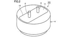
- FIG. 2 shows the ultrasonic sensor 101 turned over.
- the case 4 has an opening 19.
- the opening 19 is closed by a lid 11.
- a cross-sectional view of the ultrasonic sensor 101 is shown in FIG.
- the two external terminals 8 are arranged to protrude from the filling material 12. Each of the two external terminals 8 penetrates the lid 11.
- Case 4 is formed of, for example, a metal.
- Case 4 is formed integrally, for example.
- the case 4 has a base 3 and the surface 3 a visible in FIG. 1 comprises the outer surface of the base 3.
- the ultrasonic sensor 101 includes a cylindrical case 4 having a bottom plate 3 and a piezoelectric vibrating element 7 mounted on the bottom plate 3 inside the case 4.
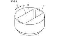
- the case 4 has an internal space 20 which is a recess dug down toward the bottom plate.
- the inner space 20 is filled with a filler 12.
- the internal space 20 is closed by a lid 11.
- the lid 11 is formed of, for example, an insulator.
- the inner space 20 is filled with a filler 12.
- one of the two external terminals 8 and the case 4 are electrically connected by the lead wire 9a.
- the other of the two external terminals 8 and the piezoelectric vibrating element 7 are electrically connected by the lead wire 9 b.
- the piezoelectric vibrating element 7 has two electrodes. One of the two electrodes of the piezoelectric vibrating element 7 is electrically connected to the lead wire 9 b, and the other is electrically connected to the bottom plate 3 of the case 4.
- FIG. 5 shows the case 4 as viewed from the side of the surface 3a.
- the internal space 20 has a shape in which one direction parallel to the bottom plate 3 is a longitudinal direction 91.
- the case 4 is viewed from the side of the opening 19 as shown in FIG.
- FIG. 7 is a sectional view taken along the line VII-VII in FIG.
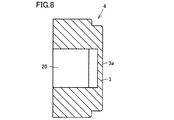
- FIG. 8 shows a cross-sectional view taken along line VIII-VIII in FIG.
- the case 4 has a cylindrical shape extending from the bottom plate 3 in a direction 90 perpendicular to the bottom plate 3 and a first portion 41 having a first length D1 along the longitudinal direction 91 of the outer shape, A second length having a cylindrical shape which is disposed on the side far from the bottom plate 3 of the portion 41 and which is concentric with the first portion 41 and whose diameter along the longitudinal direction 91 of the outer shape is larger than the first length D1 And a second portion 42 that is D2. As shown in FIG. 6, it is inside the second portion 42 of the internal space 20 than the maximum value L1 of the length along the longitudinal direction 91 of the portion of the internal space 20 inside the first portion 41. The maximum value L2 of the length along the longitudinal direction 91 of the portion is larger.
- the bottom plate 3 plays the role of a diaphragm.
- the application of the electrical signal to the piezoelectric vibrating element 7 causes the piezoelectric vibrating element 7 to vibrate.
- the vibration caused by the piezoelectric vibrating element 7 vibrates the bottom plate 3 and sends out an ultrasonic wave from the surface 3a to the outside.
- the ultrasonic wave flying from the outside to the surface 3 a vibrates the bottom plate 3. This vibration can be detected as an electrical signal by the piezoelectric vibration element 7.
- vertical directivity can be improved as compared with the conventional structure. That is, the angle range that can be sensed with high sensitivity can be narrowed. The reason will be described in detail below.
- L1 corresponds to a dimension obtained by subtracting twice the thickness of the outer peripheral wall of the first portion 41 from D1, which is a diameter along the longitudinal direction 91 of the first portion 41, it is perpendicular according to the outer shape of the first portion 41
- the directivity is fixed.
- the outer shape of the first portion 41 can not be enlarged because it is restricted by the circumstances of the installation place of the ultrasonic sensor and the like. Therefore, the upper limit of D1 is determined.
- the upper limit of L1 is determined by the upper limit of D1, and there is a limit to the improvement of the vertical directivity of the ultrasonic sensor.
- L1 and L2 have different values, and L2 is larger than L1, so L2 can be increased without changing L1. Even when D1 is determined by the circumstances of the installation place of the ultrasonic sensor and the upper limit of L1 is determined thereby, L2 can be increased.
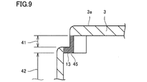
- a portion 45 shown in FIG. 9 also plays a role of a vibrating surface.
- the portion 45 is shown with fine hatching for the convenience of description.
- the portion 45 is a combination of the outer peripheral wall of the first portion 41 and the portion of the step 13 parallel to the bottom plate 3.
- An outer peripheral wall of the second portion 42 is surrounded, and a virtual surface parallel to the bottom plate 3 can be regarded as a pseudo vibration surface.
- the maximum value of the length along the inner longitudinal direction 91 is L2, vertical directivity can be determined by L2 larger than L1, and vertical directivity can be improved over conventional structures. Can.
- the ultrasonic sensor When the ultrasonic sensor is attached to a vehicle or the like, for example, a hole is generally provided in a bumper so that only the surface 3 a of the bottom plate 3 is exposed from the hole. Therefore, when discussing the design of the ultrasonic sensor in a state of being attached to a vehicle or the like, the diameter of the surface 3a becomes a problem. In the present embodiment, it is not necessary to change the diameter of the surface 3a from the conventional one because D1 does not need to be changed to increase L2. Therefore, in the present embodiment, vertical directivity can be improved without impairing the design when it is attached to a vehicle or the like.
- FIG. 10 shows a graph in which vertical directivity is compared between the ultrasonic sensor of the conventional structure and the ultrasonic sensor 101 shown in the present embodiment.
- Line 51 represents the vertical directivity obtained with an ultrasonic sensor of conventional construction.
- a line 52 represents the vertical directivity obtained by the ultrasonic sensor 101 shown in the present embodiment.
- An example of a situation in which the ultrasonic sensor 101 is attached to the rear of the vehicle 60 and used is shown in FIG.
- the main lobe 61 and the side lobes 62 are shown in FIG.
- the ultrasonic sensor 101 is expected to detect an obstacle when it is behind the vehicle 60, but the ground 65 should not.
- the main lobes 61 and the side lobes 62 indicate regions where object detection by ultrasonic waves is possible.
- FIG. 10 shows a graph in which vertical directivity is compared between the ultrasonic sensor of the conventional structure and the ultrasonic sensor 101 shown in the present embodiment.
- Line 51 represents the vertical directivity obtained with an ultrasonic sensor
- the central one of the three mountains corresponds to the main lobe 61, and the small peaks on both sides thereof correspond to the side lobes 62.
- the mountain corresponding to the main lobe 61 is preferably as narrow as possible, but as shown in FIG. 10, the width of the mountain in the line 52 is smaller than that in the line 51. Therefore, it can be seen that the narrowing of the main lobe 61 is realized, and the vertical directivity is improved.
- the mountain of the side lobe 62 be small.
- the mountain corresponding to the side lobe 62 be as low as possible, but as shown in FIG. 10, the mountain corresponding to the side lobe 62 is lower in the line 52 than in the line 51. Therefore, it can be seen that by employing the ultrasonic sensor 101 shown in the present embodiment, the reduction of the side lobes 62 is realized, and the vertical directivity is improved.
- the portion inside the first portion 41 and the portion inside the second portion 42 form the step 13. Is preferred.
- the shape of the inner surface can be rapidly changed at the transition from the first portion 41 to the second portion 42. Therefore, even if the difference between L1 and L2 is large, the first portion 41 and the second portion 42 can be connected.
- the outer shape of the inner space 20 at both ends in the longitudinal direction 91 of the inner space 20 is curved along the outer shape of the case 4 Is preferred.
- the vibration of the piezoelectric vibrating element 7 can be spread in the longitudinal direction 91, and as a result, the vertical directivity can be narrowed.
- all of the internal space 20 is filled with one type of filler 12, but this is merely an example.
- the interior space 20 may be filled by a combination of two or more materials.
- the filler 12 does not necessarily completely fill all of the internal space 20, but may be partially filled.
- the filler 12 be disposed so as to fill at least a part of the inner space 20.
- the piezoelectric vibrating element 7 can be protected.
- Filler 12 may be, for example, silicone.
- the ultrasonic sensor may have a structure without the lid 11. It is not essential that the inner space 20 be filled with the filler 12. The same applies to the following embodiments.
- FIG. 14 shows a cross-sectional view along the line XIV-XIV in FIG.
- FIG. 15 shows a cross-sectional view taken along line XV-XV in FIG.
- the case 4i is formed of, for example, a metal as in the case 4 described in the first embodiment.
- the case 4i includes the first portion 41 and the second portion 42 as in the case 4 described in the first embodiment. As shown in FIG. 13, it is inside the second portion 42 of the internal space 20 than the maximum value L1 of the length along the longitudinal direction 91 of the portion of the internal space 20 inside the first portion 41.
- the maximum value L2 of the length along the longitudinal direction 91 of the portion is larger.
- the portion inside the first portion 41 and the portion inside the second portion 42 form a step 13.
- the portion inside the first portion 41 and the portion inside the second portion 42 form the step 14 There is no.
- the two sides having the step 14 are linear.
- the two sides having the step 14 are parallel to the longitudinal direction 91. As shown in FIG. 13, the step 13 and the step 14 may be connected.
- FIG. 16 shows a plan view of the case 4j and two external terminals 8 protruding from the case 4 j.
- a plan view of the case 4j is shown in FIG.
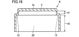
- FIG. 18 shows a cross-sectional view taken along line XVIII-XVIII in FIG.
- FIG. 19 shows a sectional view taken along line XIX-XIX in FIG.
- the case 4 j includes the first portion 41 and the second portion 42 as in the case 4 described in the first embodiment. As shown in FIG. 17, it is inside the second portion 42 of the internal space 20 than the maximum value L1 of the length along the longitudinal direction 91 of the portion of the internal space 20 inside the first portion 41. The maximum value L2 of the length along the longitudinal direction 91 of the portion is larger. As shown in FIG. 17, when viewed in the direction perpendicular to the bottom plate 3, the internal space 20 has an elliptical shape. At both ends in the longitudinal direction 91 of the internal space 20, the portion inside the first portion 41 and the portion inside the second portion 42 form a step 13.
- Embodiment 4 An ultrasonic sensor according to a fourth embodiment of the present invention will be described with reference to FIGS. 20-23.
- the external appearance of the ultrasonic sensor 104 in the present embodiment is shown in FIG.
- the ultrasonic sensor 104 includes a case 4k and two external terminals 8 projecting from the case 4k.
- a plan view of the case 4k is shown in FIG.
- FIG. 22 shows a sectional view taken along line XXII-XXII in FIG.
- FIG. 23 is a sectional view taken along line XXIII-XXIII in FIG.
- the case 4 k includes the first portion 41 and the second portion 42 as in the case 4 described in the first embodiment. As shown in FIG. 21, it is inside the second portion 42 of the internal space 20 than the maximum value L1 of the length along the longitudinal direction 91 of the portion inside the first portion 41 of the internal space 20. The maximum value L2 of the length along the longitudinal direction 91 of the portion is larger. As shown in FIG. 21, when viewed in the direction perpendicular to the bottom plate 3, the internal space 20 has an elliptical shape. At both ends in the longitudinal direction 91 of the internal space 20, the portion inside the first portion 41 and the portion inside the second portion 42 form a step 13. At both ends in the width direction 92 of the internal space 20, the portion inside the first portion 41 and the portion inside the second portion 42 form steps 14. As shown in FIG. 21, the step 13 and the step 14 may be connected.
- the same effect as that of the first embodiment can be obtained. So far, four configurations have been described in the first to fourth embodiments, but the first embodiment is particularly preferable.
- the internal space 20 has two sides parallel to the longitudinal direction 91 when viewed from the direction perpendicular to the bottom plate 3, and the two sides are the inside of the first portion 41. It is preferable that the width of the internal space 20 of the part which is the same as the width of the internal space of the part which is the inside of the second part. In the example shown in FIG. 6, these two widths are both equal to W.
- the ultrasonic sensor according to the fifth embodiment of the present invention will be described with reference to FIG.
- a cross-sectional view of the ultrasonic sensor 105 in the present embodiment is shown in FIG.
- the ultrasonic sensor 105 includes a case 4 and one lead wire 16 projecting from the case 4.
- the piezoelectric vibrating element 7 is mounted on the bottom plate 3 of the case 4.
- the inner space 20 of Case 4 is divided into three layers.
- Filler 12 may be, for example, silicone.
- a sound absorbing material 15 is disposed in the second layer closest to the bottom plate 3.
- a substrate 10 is disposed on the surface of the sound absorbing material 15.
- the layer farthest from the bottom plate 3 is filled with the filler 12.
- the sound absorbing material 15 may be, for example, any of felt, silicone sponge and the like.
- a part of the lead wire 16 is in the inner space 20 of the case 4 and the other part extends outside the case 4.
- One end of the lead 16 is electrically connected to the substrate 10.
- a portion of the lead wire 16 to be connected to the substrate 10 is covered with a filler 12.
- a connector 17 is provided at the other end of the lead wire 16.
- At least two wires are included in the lead wire 16.
- the first wiring on the surface of the substrate 10 and the case 4 are connected by lead wires 9 a.
- the second wiring on the surface of the substrate 10 and the piezoelectric vibrating element 7 are connected by the lead wire 9 b.
- the lid 11 is not provided, and the upper surface of the filler 12 is exposed as it is, but such a configuration may be employed.
- a lid may be disposed to cover the upper surface of the filler 12.
- the same effect as that of the first embodiment can be obtained.
- the sound absorbing material 15 in the internal space 20
- the back radiation from the piezoelectric vibrating element 7 can be reduced, and an effect such as reduction of reverberation can be obtained.
- Reference Signs List 3 base plate, 3a surface, 4,4i, 4j case, 7 piezoelectric vibrating element, 8 external terminal, 9a, 9b lead wire, 10 substrate, 11 lid, 12 filler, 13, 14 step, 15 sound absorbing material, 16 lead , 17 connectors, 19 openings, 20 internal spaces, 41 first parts, 42 second parts, 45 parts, 51, 52 lines, 60 vehicles, 61 main lobes, 62 side lobes, 65 ground, 90 (vertical to bottom plate Direction), 91 longitudinal direction, 92 width direction, 101, 102, 103, 104, 105 ultrasonic sensors.
Landscapes
- Engineering & Computer Science (AREA)
- Radar, Positioning & Navigation (AREA)
- Remote Sensing (AREA)
- Physics & Mathematics (AREA)
- Computer Networks & Wireless Communication (AREA)
- General Physics & Mathematics (AREA)
- Acoustics & Sound (AREA)
- Signal Processing (AREA)
- Transducers For Ultrasonic Waves (AREA)
- Measurement Of Velocity Or Position Using Acoustic Or Ultrasonic Waves (AREA)
Abstract
超音波センサ(101)は、底板(3)を有するケース(4)と、底板(3)上に搭載された圧電振動素子(7)とを備える。ケース(4)は底板(3)に向かって掘り下げられた凹部である内部空間(20)を有し、底板(3)に垂直な方向から見たとき、内部空間(20)は、底板(3)に平行な1つの方向を長手方向(91)とする形状を有し、ケース(4)は、筒形状を有して外形の長手方向(91)に沿った径が第1の長さD1である第1部分(41)と、筒形状を有して外形の長手方向(91)に沿った径が第1の長さD1よりも大きい第2の長さD2である第2部分(42)とを含む。内部空間(20)のうち第1部分(41)の内側にある部分の長手方向(91)に沿った長さの最大値よりも、内部空間(20)のうち第2部分(42)の内側にある部分の長手方向(91)に沿った長さの最大値の方が大きい。
Description
本発明は、超音波センサに関するものである。
超音波センサは、たとえば車両の後部に搭載してバックソナーとして用いられる。この場合、超音波センサは、車両の後方に向けて超音波を送信する一方、車両後方の障害物から反射されて戻ってきた超音波を受信する。送信した超音波と受信した超音波との関係を電気的に処理して得られたデータに基づいて距離情報を求めることができる。この距離情報を車両後部に対する障害物の相対的な位置関係を示すデータとして車両の運転制御に利用することができる。そのような用途に用いられうる超音波センサの一例が、特開2002-209294号公報(特許文献1)に記載されている。
超音波センサにおいて垂直指向性が十分でないと、不所望の対象物を誤検知してしまう場合がある。超音波センサによる検知の精度を上げるために、垂直指向性をさらに改善することが求められている。また、超音波センサを車両などに取り付けた際の外観の良否すなわち意匠性も問題となる。
そこで、本発明は、車両などに取り付けた際の意匠性を損なうことなく、垂直指向性を改善することを目的とする。
上記目的を達成するため、本発明に基づく超音波センサは、底板を有する筒状のケースと、上記ケースの内側において上記底板上に搭載された圧電振動素子とを備え、上記ケースは上記底板に向かって掘り下げられた凹部である内部空間を有し、上記底板に垂直な方向から見たとき、上記内部空間は、上記底板に平行な1つの方向を長手方向とする形状を有し、上記ケースは、上記底板から上記底板に垂直な方向に延在する筒形状を有して外形の上記長手方向に沿った径が第1の長さである第1部分と、上記第1部分の上記底板から遠い側に配置され、上記第1部分と同心状である筒形状を有して外形の上記長手方向に沿った径が上記第1の長さよりも大きい第2の長さである第2部分とを含み、上記内部空間のうち上記第1部分の内側にある部分の上記長手方向に沿った長さの最大値よりも、上記内部空間のうち上記第2部分の内側にある部分の上記長手方向に沿った長さの最大値の方が大きい。
本発明によれば、車両などに取り付けた際の意匠性を損なうことなく、垂直指向性を改善することができる。
図面において示す寸法比は、必ずしも忠実に現実のとおりを表しているとは限らず、説明の便宜のために寸法比を誇張して示している場合がある。以下の説明において、上または下の概念に言及する際には、絶対的な上または下を意味するとは限らず、図示された姿勢の中での相対的な上または下を意味する場合がある。
(実施の形態1)
図1~図8を参照して、本発明に基づく実施の形態1における超音波センサについて説明する。本実施の形態における超音波センサ101の外観を図1に示す。超音波センサ101は、ケース4と、ケース4から突出する2本の外部端子8とを備える。ケース4は、表面3aを有する。表面3aはたとえば円形である。超音波センサ101を裏返したところを図2に示す。ケース4は、開口部19を有する。開口部19は蓋11によって塞がれている。超音波センサ101の断面図を図3に示す。2本の外部端子8は充填材12の中から突出するように配置されている。2本の外部端子8の各々は、蓋11を貫通している。ケース4はたとえば金属で形成されている。ケース4は、たとえば一体的に形成されたものである。ケース4は底板3を有し、図1で見えていた表面3aは底板3の外側表面を含む。
図1~図8を参照して、本発明に基づく実施の形態1における超音波センサについて説明する。本実施の形態における超音波センサ101の外観を図1に示す。超音波センサ101は、ケース4と、ケース4から突出する2本の外部端子8とを備える。ケース4は、表面3aを有する。表面3aはたとえば円形である。超音波センサ101を裏返したところを図2に示す。ケース4は、開口部19を有する。開口部19は蓋11によって塞がれている。超音波センサ101の断面図を図3に示す。2本の外部端子8は充填材12の中から突出するように配置されている。2本の外部端子8の各々は、蓋11を貫通している。ケース4はたとえば金属で形成されている。ケース4は、たとえば一体的に形成されたものである。ケース4は底板3を有し、図1で見えていた表面3aは底板3の外側表面を含む。
超音波センサ101は、底板3を有する筒状のケース4と、ケース4の内側において底板3上に搭載された圧電振動素子7とを備える。ケース4は底板に向かって掘り下げられた凹部である内部空間20を有する。内部空間20には充填材12が充填されている。内部空間20は蓋11によって塞がれている。蓋11はたとえば絶縁体で形成されている。内部空間20には充填材12が充填されている。図3に示すように、2本の外部端子8のうち一方とケース4とがリード線9aによって電気的に接続されている。2本の外部端子8のうち他方と圧電振動素子7とがリード線9bによって電気的に接続されている。図3では、詳しく表示していないが、実際には圧電振動素子7は2つの電極を有している。圧電振動素子7の2つの電極のうち一方がリード線9bと電気的に接続しており、他方はケース4の底板3と電気的に接続している。
ケース4を単独で取り出したところを図4に示す。ケース4を表面3aの側から見たところを図5に示す。ケース4を底板3に垂直な方向90から見たとき、内部空間20は、底板3に平行な1つの方向を長手方向91とする形状を有する。ケース4を開口部19の側から見たところを図6に示す。図6におけるVII-VII線に関する矢視断面図を図7に示す。図6におけるVIII-VIII線に関する矢視断面図を図8に示す。
ケース4は、底板3から底板3に垂直な方向90に延在する筒形状を有して外形の長手方向91に沿った径が第1の長さD1である第1部分41と、第1部分41の底板3から遠い側に配置され、第1部分41と同心状である筒形状を有して外形の長手方向91に沿った径が第1の長さD1よりも大きい第2の長さD2である第2部分42とを含む。図6に示すように、内部空間20のうち第1部分41の内側にある部分の長手方向91に沿った長さの最大値L1よりも、内部空間20のうち第2部分42の内側にある部分の長手方向91に沿った長さの最大値L2の方が大きい。
底板3は振動板の役割を果たす。電気信号が圧電振動素子7に付与されることによって圧電振動素子7が振動する。圧電振動素子7によって引き起こされた振動が底板3を振動させ、超音波を表面3aから外部に送り出す。外部から表面3aへと飛来した超音波は底板3を振動させる。この振動を圧電振動素子7によって電気信号として検出することができる。
本実施の形態では、従来の構造に比べて垂直指向性を改善することができる。すなわち、高感度にセンシングすることができる角度範囲を狭くすることができる。この理由について、以下に詳しく説明する。
垂直指向性を向上させるためには、L1をできるだけ大きくすることが好ましい。従来の構造、すなわち、内部空間20のうちL1とL2とが等しい構造の場合には、L1によって垂直指向性が決まってしまう。L1は、第1部分41の長手方向91に沿った径であるD1から第1部分41の外周壁の厚みの2倍を引いた寸法に相当するので、結局、第1部分41の外形によって垂直指向性が定まってしまう。第1部分41の外形は超音波センサの設置場所の事情などにより制約があるので大きくすることはできない。したがって、D1の上限は決まってしまう。D1の上限によりL1の上限が決まってしまい、超音波センサの垂直指向性の向上には限界があった。
しかし、本実施の形態では、L1とL2とで異なる値としており、L2の方がL1より大きいので、L1を変えることなくL2を大きくすることができる。超音波センサの設置場所の事情などによりD1が決まってしまい、これによりL1の上限が決まってしまう場合であっても、L2を大きくすることができる。本実施の形態では、底板3に加えて、図9に示す部分45も振動面の役割を果たす。図9では、説明の便宜のために部分45に細かいハッチングを付して示している。部分45は、第1部分41の外周壁と、段差13のうち底板3と平行な部分とを合わせたものである。第2部分42の外周壁が取り囲み、底板3に平行な仮想的な面を、疑似的な振動面とみなすことができる。第2部分42では、内側の長手方向91に沿った長さの最大値はL2であるので、L1より大きなL2によって垂直指向性を定めることができ、従来の構造より垂直指向性を改善することができる。
超音波センサを車両などに取り付ける際には、たとえばバンパーに孔が設けられて、この孔から底板3の表面3aだけを露出させるように取り付けられることが一般的である。したがって、車両などに取り付けた状態での超音波センサの意匠性を議論する際には、表面3aの直径が問題となる。本実施の形態では、L2を大きくするためにはD1は変える必要がないので、表面3aの直径は従来のものから変更する必要がない。よって、本実施の形態では、車両などに取り付けた際の意匠性を損なうことなく、垂直指向性を改善することができる。
実際、従来の構造の超音波センサと本実施の形態で示した超音波センサ101とで、垂直指向性を比較したグラフを図10に示す。線51が従来の構造の超音波センサで得られる垂直指向性を表す。線52が本実施の形態で示した超音波センサ101で得られる垂直指向性を表す。超音波センサ101を車両60の後部に取り付けて使用する状況の一例を図11に示す。図11には、メインローブ61とサイドローブ62とが示されている。超音波センサ101は車両60の後方に障害物がある場合にこれを検出することが期待されているが、地面65は検出すべきではない。メインローブ61およびサイドローブ62は超音波による対象物検出が可能な領域を示している。図10には、線51および線52のいずれにおいても3つの山が表れている。図10においては3つの山のうち中央の山がメインローブ61に対応し、その両側の小さな山がサイドローブ62に相当する。メインローブ61に対応する山は幅が狭ければ狭いほどよいが、図10に示すように線51に比べて線52では山の幅が狭くなっている。したがって、メインローブ61の狭幅化が実現され、垂直指向性が向上していることがわかる。さらに、図11において超音波センサ101が地面65などで反射した超音波を誤って検出しないためには、サイドローブ62の山は小さい方が好ましい。図10においてはサイドローブ62に対応する山は低ければ低いほど好ましいが、図10に示すように、線51に比べて線52ではサイドローブ62に対応する山は低くなっている。したがって、本実施の形態で示した超音波センサ101を採用することで、サイドローブ62の低減が実現され、垂直指向性が向上していることがわかる。
なお、本実施の形態で示したように、内部空間20の長手方向91の両端においては、第1部分41の内側にある部分と第2部分42の内側にある部分とが段差13をなしていることが好ましい。この構成を採用することにより、第1部分41から第2部分42へと遷移する部分において内面の形状を急激に変化させることができる。したがって、L1とL2との差がたとえ大きくても第1部分41と第2部分42とをつなぐことができる。
本実施の形態で示したように、底板3に垂直な方向90から見たとき、内部空間20の長手方向91の両端における内部空間20の外形は、ケース4の外形に沿って湾曲していることが好ましい。この構成を採用することにより、圧電振動素子7の振動を長手方向91に関して広げることができ、その結果、垂直指向性を狭くすることができる。
本実施の形態では、内部空間20の全てを1種類の充填材12で満たしている例を示したが、これはあくまで一例である。内部空間20は2種類以上の材料の組合せによって満たされていてもよい。充填材12は内部空間20の全てを完全に満たしているとは限らず、一部のみを満たしている構成であってもよい。
本実施の形態で示したように、内部空間20の少なくとも一部を満たすように充填材12が配置されていることが好ましい。この構成を採用することにより、圧電振動素子7を保護することができる。充填材12の配置の仕方によっては、圧電振動素子7付近への水、粉塵などの侵入を軽減または防止することができる。充填材12はたとえばシリコーンであってよい。
本実施の形態では、蓋11によって開口部19が塞がれている例を示したが、蓋11の存在は必須ではない。超音波センサは、蓋11がない構造であってもよい。内部空間20に充填材12が充填されていることも必須ではない。これらのことは、以下の実施の形態においても同様にあてはまる。
(実施の形態2)
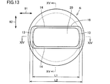
図12~図15を参照して、本発明に基づく実施の形態2における超音波センサについて説明する。本実施の形態における超音波センサ102の外観を図12に示す。超音波センサ102は、ケース4iと、ケース4iから突出する2本の外部端子8とを備える。ケース4iの平面図を図13に示す。図13におけるXIV-XIV線に関する矢視断面図を図14に示す。図13におけるXV-XV線に関する矢視断面図を図15に示す。
図12~図15を参照して、本発明に基づく実施の形態2における超音波センサについて説明する。本実施の形態における超音波センサ102の外観を図12に示す。超音波センサ102は、ケース4iと、ケース4iから突出する2本の外部端子8とを備える。ケース4iの平面図を図13に示す。図13におけるXIV-XIV線に関する矢視断面図を図14に示す。図13におけるXV-XV線に関する矢視断面図を図15に示す。
ケース4iは、実施の形態1で説明したケース4と同様に、たとえば金属で形成されている。以下の実施の形態に登場するケースについても同様である。ケース4iは、実施の形態1で説明したケース4と同様に、第1部分41と第2部分42とを含む。図13に示すように、内部空間20のうち第1部分41の内側にある部分の長手方向91に沿った長さの最大値L1よりも、内部空間20のうち第2部分42の内側にある部分の長手方向91に沿った長さの最大値L2の方が大きい。内部空間20の長手方向91の両端においては、第1部分41の内側にある部分と第2部分42の内側にある部分とが段差13をなしている。長手方向91と垂直な方向を幅方向92とすると、内部空間20の幅方向92の両端においては、第1部分41の内側にある部分と第2部分42の内側にある部分とが段差14をなしている。段差14を有する2本の辺は直線状となっている。段差14を有する2本の辺は長手方向91に平行となっている。図13に示すように、段差13と段差14とはつながっていてもよい。
本実施の形態においても、実施の形態1と同様の効果を得ることができる。
(実施の形態3)
図16~図19を参照して、本発明に基づく実施の形態3における超音波センサについて説明する。本実施の形態における超音波センサ103の外観を図16に示す。超音波センサ103は、ケース4jと、ケース4jから突出する2本の外部端子8とを備える。ケース4jの平面図を図17に示す。図17におけるXVIII-XVIII線に関する矢視断面図を図18に示す。図17におけるXIX-XIX線に関する矢視断面図を図19に示す。
(実施の形態3)
図16~図19を参照して、本発明に基づく実施の形態3における超音波センサについて説明する。本実施の形態における超音波センサ103の外観を図16に示す。超音波センサ103は、ケース4jと、ケース4jから突出する2本の外部端子8とを備える。ケース4jの平面図を図17に示す。図17におけるXVIII-XVIII線に関する矢視断面図を図18に示す。図17におけるXIX-XIX線に関する矢視断面図を図19に示す。
ケース4jは、実施の形態1で説明したケース4と同様に、第1部分41と第2部分42とを含む。図17に示すように、内部空間20のうち第1部分41の内側にある部分の長手方向91に沿った長さの最大値L1よりも、内部空間20のうち第2部分42の内側にある部分の長手方向91に沿った長さの最大値L2の方が大きい。図17に示すように、底板3に垂直な方向から見たとき、内部空間20は楕円形状となっている。内部空間20の長手方向91の両端においては、第1部分41の内側にある部分と第2部分42の内側にある部分とが段差13をなしている。
本実施の形態においても、実施の形態1と同様の効果を得ることができる。
(実施の形態4)
図20~図23を参照して、本発明に基づく実施の形態4における超音波センサについて説明する。本実施の形態における超音波センサ104の外観を図20に示す。超音波センサ104は、ケース4kと、ケース4kから突出する2本の外部端子8とを備える。ケース4kの平面図を図21に示す。図21におけるXXII-XXII線に関する矢視断面図を図22に示す。図21におけるXXIII-XXIII線に関する矢視断面図を図23に示す。
(実施の形態4)
図20~図23を参照して、本発明に基づく実施の形態4における超音波センサについて説明する。本実施の形態における超音波センサ104の外観を図20に示す。超音波センサ104は、ケース4kと、ケース4kから突出する2本の外部端子8とを備える。ケース4kの平面図を図21に示す。図21におけるXXII-XXII線に関する矢視断面図を図22に示す。図21におけるXXIII-XXIII線に関する矢視断面図を図23に示す。
ケース4kは、実施の形態1で説明したケース4と同様に、第1部分41と第2部分42とを含む。図21に示すように、内部空間20のうち第1部分41の内側にある部分の長手方向91に沿った長さの最大値L1よりも、内部空間20のうち第2部分42の内側にある部分の長手方向91に沿った長さの最大値L2の方が大きい。図21に示すように、底板3に垂直な方向から見たとき、内部空間20は楕円形状となっている。内部空間20の長手方向91の両端においては、第1部分41の内側にある部分と第2部分42の内側にある部分とが段差13をなしている。内部空間20の幅方向92の両端においては、第1部分41の内側にある部分と第2部分42の内側にある部分とが段差14をなしている。図21に示すように、段差13と段差14とはつながっていてもよい。
本実施の形態においても、実施の形態1と同様の効果を得ることができる。
ここまで実施の形態1~4で4通りの構成について説明したが、特に実施の形態1が好ましい。実施の形態1で示したように、内部空間20は、底板3に垂直な方向から見たとき、長手方向91に平行な2辺を有し、前記2辺においては、第1部分41の内側である部分の内部空間20の幅と、前記第2部分の内側である部分の前記内部空間の幅とが同じであることが好ましい。図6に示した例では、これら2つの幅はいずれも等しくWである。
ここまで実施の形態1~4で4通りの構成について説明したが、特に実施の形態1が好ましい。実施の形態1で示したように、内部空間20は、底板3に垂直な方向から見たとき、長手方向91に平行な2辺を有し、前記2辺においては、第1部分41の内側である部分の内部空間20の幅と、前記第2部分の内側である部分の前記内部空間の幅とが同じであることが好ましい。図6に示した例では、これら2つの幅はいずれも等しくWである。
(実施の形態5)
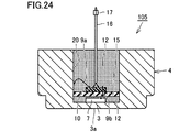
図24を参照して、本発明に基づく実施の形態5における超音波センサについて説明する。本実施の形態における超音波センサ105の断面図を図24に示す。超音波センサ105は、ケース4と、ケース4から突出する1本のリード線16とを備える。ケース4の底板3に圧電振動素子7が搭載されている。ケース4の内部空間20は、3層に分かれている。底板3に最も近い層においては、充填材12が充填されている。充填材12はたとえばシリコーンであってよい。底板3から2番目に近い層においては吸音材15が配置されている。吸音材15の表面に基板10が配置されている。底板3から最も遠い層には充填材12が充填されている。吸音材15は、たとえばフェルト、シリコーンスポンジなどのいずれかであってよい。リード線16の一部はケース4の内部空間20にあり、他の一部はケース4の外に延在している。リード線16の一方の端は基板10に電気的に接続されている。リード線16の基板10と接続する部分は充填材12に覆われている。リード線16の他方の端にはコネクタ17が設けられている。リード線16の内部には少なくとも2本の配線が含まれている。基板10の表面の第1の配線とケース4とがリード線9aによって接続されている。基板10の表面の第2の配線と圧電振動素子7とがリード線9bによって接続されている。図24に示した例では、蓋11はなく、充填材12の上面がそのまま外部に露出しているが、このような構成であってもよい。充填材12の上面を覆うように蓋を配置してもよい。
図24を参照して、本発明に基づく実施の形態5における超音波センサについて説明する。本実施の形態における超音波センサ105の断面図を図24に示す。超音波センサ105は、ケース4と、ケース4から突出する1本のリード線16とを備える。ケース4の底板3に圧電振動素子7が搭載されている。ケース4の内部空間20は、3層に分かれている。底板3に最も近い層においては、充填材12が充填されている。充填材12はたとえばシリコーンであってよい。底板3から2番目に近い層においては吸音材15が配置されている。吸音材15の表面に基板10が配置されている。底板3から最も遠い層には充填材12が充填されている。吸音材15は、たとえばフェルト、シリコーンスポンジなどのいずれかであってよい。リード線16の一部はケース4の内部空間20にあり、他の一部はケース4の外に延在している。リード線16の一方の端は基板10に電気的に接続されている。リード線16の基板10と接続する部分は充填材12に覆われている。リード線16の他方の端にはコネクタ17が設けられている。リード線16の内部には少なくとも2本の配線が含まれている。基板10の表面の第1の配線とケース4とがリード線9aによって接続されている。基板10の表面の第2の配線と圧電振動素子7とがリード線9bによって接続されている。図24に示した例では、蓋11はなく、充填材12の上面がそのまま外部に露出しているが、このような構成であってもよい。充填材12の上面を覆うように蓋を配置してもよい。
本実施の形態においても、実施の形態1と同様の効果を得ることができる。本実施の形態で示したように、内部空間20に吸音材15を配置することとすれば、圧電振動素子7からの背面放射を低減することができ、残響の低減などの効果が得られる。
なお、上記実施の形態のうち複数を適宜組み合わせて採用してもよい。
なお、今回開示した上記実施の形態はすべての点で例示であって制限的なものではない。本発明の範囲は請求の範囲によって示され、請求の範囲と均等の意味および範囲内でのすべての変更を含むものである。
なお、今回開示した上記実施の形態はすべての点で例示であって制限的なものではない。本発明の範囲は請求の範囲によって示され、請求の範囲と均等の意味および範囲内でのすべての変更を含むものである。
3 底板、3a 表面、4,4i,4j ケース、7 圧電振動素子、8 外部端子、9a,9b リード線、10 基板、11 蓋、12 充填材、13,14 段差、15 吸音材、16 リード線、17 コネクタ、19 開口部、20 内部空間、41 第1部分、42 第2部分、45 部分、51,52 線、60 車両、61 メインローブ、62 サイドローブ、65 地面、90 (底板に垂直な)方向、91 長手方向、92 幅方向、101,102,103,104,105 超音波センサ。
Claims (5)
- 底板を有する筒状のケースと、
前記ケースの内側において前記底板上に搭載された圧電振動素子とを備え、
前記ケースは前記底板に向かって掘り下げられた凹部である内部空間を有し、
前記底板に垂直な方向から見たとき、前記内部空間は、前記底板に平行な1つの方向を長手方向とする形状を有し、
前記ケースは、
前記底板から前記底板に垂直な方向に延在する筒形状を有して外形の前記長手方向に沿った径が第1の長さである第1部分と、
前記第1部分の前記底板から遠い側に配置され、前記第1部分と同心状である筒形状を有して外形の前記長手方向に沿った径が前記第1の長さよりも大きい第2の長さである第2部分とを含み、
前記内部空間のうち前記第1部分の内側にある部分の前記長手方向に沿った長さの最大値よりも、前記内部空間のうち前記第2部分の内側にある部分の前記長手方向に沿った長さの最大値の方が大きい、超音波センサ。 - 前記内部空間の前記長手方向の両端においては、前記第1部分の内側にある部分と前記第2部分の内側にある部分とが段差をなしている、請求項1に記載の超音波センサ。
- 前記底板に垂直な方向から見たとき、前記内部空間の前記長手方向の両端における前記内部空間の外形は、前記ケースの外形に沿って湾曲している、請求項1または2に記載の超音波センサ。
- 前記内部空間の少なくとも一部を満たすように充填材が配置されている、請求項1から3のいずれかに記載の超音波センサ。
- 前記内部空間は、前記底板に垂直な方向から見たとき、前記長手方向に平行な2辺を有し、前記2辺においては、前記第1部分の内側である部分の前記内部空間の幅と、前記第2部分の内側である部分の前記内部空間の幅とが同じである、請求項1から4のいずれかに記載の超音波センサ。
Priority Applications (4)
| Application Number | Priority Date | Filing Date | Title |
|---|---|---|---|
| EP18858712.5A EP3687191B1 (en) | 2017-09-21 | 2018-08-21 | Ultrasonic sensor |
| JP2019543490A JP6863466B2 (ja) | 2017-09-21 | 2018-08-21 | 超音波センサ |
| CN201880060510.4A CN111133772A (zh) | 2017-09-21 | 2018-08-21 | 超声波传感器 |
| US16/804,080 US20200200885A1 (en) | 2017-09-21 | 2020-02-28 | Ultrasonic sensor |
Applications Claiming Priority (2)
| Application Number | Priority Date | Filing Date | Title |
|---|---|---|---|
| JP2017181380 | 2017-09-21 | ||
| JP2017-181380 | 2017-09-21 |
Related Child Applications (1)
| Application Number | Title | Priority Date | Filing Date |
|---|---|---|---|
| US16/804,080 Continuation US20200200885A1 (en) | 2017-09-21 | 2020-02-28 | Ultrasonic sensor |
Publications (1)
| Publication Number | Publication Date |
|---|---|
| WO2019058842A1 true WO2019058842A1 (ja) | 2019-03-28 |
Family
ID=65811372
Family Applications (1)
| Application Number | Title | Priority Date | Filing Date |
|---|---|---|---|
| PCT/JP2018/030840 Ceased WO2019058842A1 (ja) | 2017-09-21 | 2018-08-21 | 超音波センサ |
Country Status (5)
| Country | Link |
|---|---|
| US (1) | US20200200885A1 (ja) |
| EP (1) | EP3687191B1 (ja) |
| JP (1) | JP6863466B2 (ja) |
| CN (1) | CN111133772A (ja) |
| WO (1) | WO2019058842A1 (ja) |
Cited By (3)
| Publication number | Priority date | Publication date | Assignee | Title |
|---|---|---|---|---|
| JP2021082885A (ja) * | 2019-11-15 | 2021-05-27 | Tdk株式会社 | 超音波デバイス及び流体検出装置 |
| WO2021256047A1 (ja) * | 2020-06-17 | 2021-12-23 | パナソニックIpマネジメント株式会社 | 超音波センサ装置、および、車両 |
| WO2026063430A1 (ja) * | 2024-09-20 | 2026-03-26 | 株式会社村田製作所 | 超音波センサ |
Families Citing this family (4)
| Publication number | Priority date | Publication date | Assignee | Title |
|---|---|---|---|---|
| TWI707146B (zh) * | 2019-06-12 | 2020-10-11 | 千竣科技有限公司 | 超聲波偵測裝置 |
| USD1024818S1 (en) * | 2021-04-16 | 2024-04-30 | Chengdu Huitong West Electronic Co., Ltd. | Housing of ultrasonic sensor |
| JP1748345S (ja) * | 2022-07-05 | 2023-07-10 | 超音波センサ用筐体 | |
| DE102023102399A1 (de) | 2023-02-01 | 2024-08-01 | Dr. Ing. H.C. F. Porsche Aktiengesellschaft | Anordnung einer Kraftfahrzeugsensorvorrichtung |
Citations (3)
| Publication number | Priority date | Publication date | Assignee | Title |
|---|---|---|---|---|
| JP2002112395A (ja) * | 2000-09-26 | 2002-04-12 | Matsushita Electric Works Ltd | 超音波振動子 |
| JP2002209294A (ja) | 2001-01-10 | 2002-07-26 | Murata Mfg Co Ltd | 超音波センサ、これを備える電子機器および車両用バックソナー |
| JP2002262383A (ja) * | 2000-12-28 | 2002-09-13 | Matsushita Electric Works Ltd | 超音波振動子 |
Family Cites Families (16)
| Publication number | Priority date | Publication date | Assignee | Title |
|---|---|---|---|---|
| TW345132U (en) * | 1998-03-26 | 1998-11-11 | shi-xiong Li | Improved structure for sensor of car backing radar |
| US6250162B1 (en) * | 1998-04-24 | 2001-06-26 | Murata Manufacturing Co., Ltd. | Ultrasonic sensor |
| JP3552605B2 (ja) * | 1999-08-31 | 2004-08-11 | 松下電工株式会社 | 超音波振動子 |
| JP4304556B2 (ja) * | 1999-12-03 | 2009-07-29 | 株式会社村田製作所 | 超音波センサ |
| JP2001232294A (ja) * | 2000-02-24 | 2001-08-28 | Matsushita Electric Works Ltd | 超音波振動子 |
| CN101258772B (zh) * | 2005-09-09 | 2012-04-25 | 株式会社村田制作所 | 超声波传感器 |
| CN101072452A (zh) * | 2005-12-27 | 2007-11-14 | 中国科学院声学研究所 | 深海压电水声换能器及其制造方法 |
| DE102007008744B4 (de) * | 2006-03-15 | 2012-10-31 | Denso Corporation | Ultraschallsensor |
| JP4742924B2 (ja) * | 2006-03-15 | 2011-08-10 | 株式会社デンソー | 超音波センサ |
| JP4893322B2 (ja) * | 2006-03-23 | 2012-03-07 | 株式会社デンソー | 超音波センサ |
| JP2007282058A (ja) * | 2006-04-10 | 2007-10-25 | Nippon Ceramic Co Ltd | 超音波センサ |
| DE102006050037A1 (de) * | 2006-10-24 | 2008-04-30 | Robert Bosch Gmbh | Ultraschallwandler |
| CN101740017A (zh) * | 2008-11-12 | 2010-06-16 | 同致电子企业股份有限公司 | 哑铃形腔室的超音波换能器 |
| DE112009003590B4 (de) * | 2008-12-04 | 2018-06-14 | Murata Manufacturing Co., Ltd. | Ultraschallwandler |
| KR101553869B1 (ko) * | 2013-07-02 | 2015-09-17 | 현대모비스 주식회사 | 초음파 센서 조립체 |
| JP6493415B2 (ja) * | 2014-12-26 | 2019-04-03 | 株式会社村田製作所 | 超音波センサ |
-
2018
- 2018-08-21 CN CN201880060510.4A patent/CN111133772A/zh not_active Withdrawn
- 2018-08-21 EP EP18858712.5A patent/EP3687191B1/en active Active
- 2018-08-21 JP JP2019543490A patent/JP6863466B2/ja active Active
- 2018-08-21 WO PCT/JP2018/030840 patent/WO2019058842A1/ja not_active Ceased
-
2020
- 2020-02-28 US US16/804,080 patent/US20200200885A1/en not_active Abandoned
Patent Citations (3)
| Publication number | Priority date | Publication date | Assignee | Title |
|---|---|---|---|---|
| JP2002112395A (ja) * | 2000-09-26 | 2002-04-12 | Matsushita Electric Works Ltd | 超音波振動子 |
| JP2002262383A (ja) * | 2000-12-28 | 2002-09-13 | Matsushita Electric Works Ltd | 超音波振動子 |
| JP2002209294A (ja) | 2001-01-10 | 2002-07-26 | Murata Mfg Co Ltd | 超音波センサ、これを備える電子機器および車両用バックソナー |
Non-Patent Citations (1)
| Title |
|---|
| See also references of EP3687191A4 |
Cited By (4)
| Publication number | Priority date | Publication date | Assignee | Title |
|---|---|---|---|---|
| JP2021082885A (ja) * | 2019-11-15 | 2021-05-27 | Tdk株式会社 | 超音波デバイス及び流体検出装置 |
| JP7318495B2 (ja) | 2019-11-15 | 2023-08-01 | Tdk株式会社 | 超音波デバイス及び流体検出装置 |
| WO2021256047A1 (ja) * | 2020-06-17 | 2021-12-23 | パナソニックIpマネジメント株式会社 | 超音波センサ装置、および、車両 |
| WO2026063430A1 (ja) * | 2024-09-20 | 2026-03-26 | 株式会社村田製作所 | 超音波センサ |
Also Published As
| Publication number | Publication date |
|---|---|
| EP3687191A1 (en) | 2020-07-29 |
| JPWO2019058842A1 (ja) | 2020-08-27 |
| EP3687191A4 (en) | 2021-06-16 |
| US20200200885A1 (en) | 2020-06-25 |
| EP3687191B1 (en) | 2024-05-15 |
| JP6863466B2 (ja) | 2021-04-21 |
| CN111133772A (zh) | 2020-05-08 |
Similar Documents
| Publication | Publication Date | Title |
|---|---|---|
| JP6863466B2 (ja) | 超音波センサ | |
| JP4086091B2 (ja) | 超音波トランスデューサ | |
| JP4438667B2 (ja) | 超音波センサ及び超音波振動子 | |
| US6250162B1 (en) | Ultrasonic sensor | |
| US7775110B2 (en) | Ultrasonic sensor | |
| US7513158B2 (en) | Ultrasonic sensor for use in automotive vehicle | |
| CN102726064B (zh) | 超声波振动装置 | |
| JP2007147319A (ja) | 障害物検知装置 | |
| JP2007142967A (ja) | 超音波センサ | |
| JP2021028606A (ja) | 超音波センサ | |
| JP5950742B2 (ja) | 超音波送受波器 | |
| JP2005130040A (ja) | 超音波センサの実装構造 | |
| US7461555B2 (en) | Ultrasonic sensor | |
| JPWO2007091609A1 (ja) | 超音波センサ | |
| JP4182156B2 (ja) | 超音波送受波器及び電子機器 | |
| US20200260170A1 (en) | Ultrasonic sensor | |
| JP2008092444A (ja) | 超音波センサ | |
| JP2001337172A (ja) | 超音波検知器 | |
| JP5340432B2 (ja) | 超音波センサ | |
| JP7413921B2 (ja) | 超音波センサ取付構造 | |
| JP4768684B2 (ja) | 超音波センサ | |
| JP2003032794A (ja) | 超音波振動子およびその超音波振動子を有する超音波センサ | |
| JP2004159351A (ja) | 超音波センサ | |
| JP7318495B2 (ja) | 超音波デバイス及び流体検出装置 |
Legal Events
| Date | Code | Title | Description |
|---|---|---|---|
| 121 | Ep: the epo has been informed by wipo that ep was designated in this application |
Ref document number: 18858712 Country of ref document: EP Kind code of ref document: A1 |
|
| ENP | Entry into the national phase |
Ref document number: 2019543490 Country of ref document: JP Kind code of ref document: A |
|
| NENP | Non-entry into the national phase |
Ref country code: DE |
|
| ENP | Entry into the national phase |
Ref document number: 2018858712 Country of ref document: EP Effective date: 20200421 |