WO2019058944A1 - 車両フロント窓用の合せガラス - Google Patents
車両フロント窓用の合せガラス Download PDFInfo
- Publication number
- WO2019058944A1 WO2019058944A1 PCT/JP2018/032590 JP2018032590W WO2019058944A1 WO 2019058944 A1 WO2019058944 A1 WO 2019058944A1 JP 2018032590 W JP2018032590 W JP 2018032590W WO 2019058944 A1 WO2019058944 A1 WO 2019058944A1
- Authority
- WO
- WIPO (PCT)
- Prior art keywords
- intermediate film
- glass plate
- thickness
- profile
- laminated glass
- Prior art date
- Legal status (The legal status is an assumption and is not a legal conclusion. Google has not performed a legal analysis and makes no representation as to the accuracy of the status listed.)
- Ceased
Links
Images


Classifications
-
- G—PHYSICS
- G02—OPTICS
- G02B—OPTICAL ELEMENTS, SYSTEMS OR APPARATUS
- G02B27/00—Optical systems or apparatus not provided for by any of the groups G02B1/00 - G02B26/00, G02B30/00
- G02B27/01—Head-up displays
- G02B27/0101—Head-up displays characterised by optical features
-
- B—PERFORMING OPERATIONS; TRANSPORTING
- B32—LAYERED PRODUCTS
- B32B—LAYERED PRODUCTS, i.e. PRODUCTS BUILT-UP OF STRATA OF FLAT OR NON-FLAT, e.g. CELLULAR OR HONEYCOMB, FORM
- B32B17/00—Layered products essentially comprising sheet glass, or glass, slag, or like fibres
- B32B17/06—Layered products essentially comprising sheet glass, or glass, slag, or like fibres comprising glass as the main or only constituent of a layer, next to another layer of a specific material
- B32B17/10—Layered products essentially comprising sheet glass, or glass, slag, or like fibres comprising glass as the main or only constituent of a layer, next to another layer of a specific material of synthetic resin
- B32B17/10005—Layered products essentially comprising sheet glass, or glass, slag, or like fibres comprising glass as the main or only constituent of a layer, next to another layer of a specific material of synthetic resin laminated safety glass or glazing
- B32B17/1055—Layered products essentially comprising sheet glass, or glass, slag, or like fibres comprising glass as the main or only constituent of a layer, next to another layer of a specific material of synthetic resin laminated safety glass or glazing characterized by the resin layer, i.e. interlayer
- B32B17/10559—Shape of the cross-section
- B32B17/10568—Shape of the cross-section varying in thickness
-
- B—PERFORMING OPERATIONS; TRANSPORTING
- B32—LAYERED PRODUCTS
- B32B—LAYERED PRODUCTS, i.e. PRODUCTS BUILT-UP OF STRATA OF FLAT OR NON-FLAT, e.g. CELLULAR OR HONEYCOMB, FORM
- B32B17/00—Layered products essentially comprising sheet glass, or glass, slag, or like fibres
- B32B17/06—Layered products essentially comprising sheet glass, or glass, slag, or like fibres comprising glass as the main or only constituent of a layer, next to another layer of a specific material
- B32B17/10—Layered products essentially comprising sheet glass, or glass, slag, or like fibres comprising glass as the main or only constituent of a layer, next to another layer of a specific material of synthetic resin
- B32B17/10005—Layered products essentially comprising sheet glass, or glass, slag, or like fibres comprising glass as the main or only constituent of a layer, next to another layer of a specific material of synthetic resin laminated safety glass or glazing
- B32B17/10009—Layered products essentially comprising sheet glass, or glass, slag, or like fibres comprising glass as the main or only constituent of a layer, next to another layer of a specific material of synthetic resin laminated safety glass or glazing characterized by the number, the constitution or treatment of glass sheets
- B32B17/10036—Layered products essentially comprising sheet glass, or glass, slag, or like fibres comprising glass as the main or only constituent of a layer, next to another layer of a specific material of synthetic resin laminated safety glass or glazing characterized by the number, the constitution or treatment of glass sheets comprising two outer glass sheets
-
- B—PERFORMING OPERATIONS; TRANSPORTING
- B32—LAYERED PRODUCTS
- B32B—LAYERED PRODUCTS, i.e. PRODUCTS BUILT-UP OF STRATA OF FLAT OR NON-FLAT, e.g. CELLULAR OR HONEYCOMB, FORM
- B32B17/00—Layered products essentially comprising sheet glass, or glass, slag, or like fibres
- B32B17/06—Layered products essentially comprising sheet glass, or glass, slag, or like fibres comprising glass as the main or only constituent of a layer, next to another layer of a specific material
- B32B17/10—Layered products essentially comprising sheet glass, or glass, slag, or like fibres comprising glass as the main or only constituent of a layer, next to another layer of a specific material of synthetic resin
- B32B17/10005—Layered products essentially comprising sheet glass, or glass, slag, or like fibres comprising glass as the main or only constituent of a layer, next to another layer of a specific material of synthetic resin laminated safety glass or glazing
- B32B17/1055—Layered products essentially comprising sheet glass, or glass, slag, or like fibres comprising glass as the main or only constituent of a layer, next to another layer of a specific material of synthetic resin laminated safety glass or glazing characterized by the resin layer, i.e. interlayer
- B32B17/10761—Layered products essentially comprising sheet glass, or glass, slag, or like fibres comprising glass as the main or only constituent of a layer, next to another layer of a specific material of synthetic resin laminated safety glass or glazing characterized by the resin layer, i.e. interlayer containing vinyl acetal
-
- B—PERFORMING OPERATIONS; TRANSPORTING
- B32—LAYERED PRODUCTS
- B32B—LAYERED PRODUCTS, i.e. PRODUCTS BUILT-UP OF STRATA OF FLAT OR NON-FLAT, e.g. CELLULAR OR HONEYCOMB, FORM
- B32B17/00—Layered products essentially comprising sheet glass, or glass, slag, or like fibres
- B32B17/06—Layered products essentially comprising sheet glass, or glass, slag, or like fibres comprising glass as the main or only constituent of a layer, next to another layer of a specific material
- B32B17/10—Layered products essentially comprising sheet glass, or glass, slag, or like fibres comprising glass as the main or only constituent of a layer, next to another layer of a specific material of synthetic resin
- B32B17/10005—Layered products essentially comprising sheet glass, or glass, slag, or like fibres comprising glass as the main or only constituent of a layer, next to another layer of a specific material of synthetic resin laminated safety glass or glazing
- B32B17/1055—Layered products essentially comprising sheet glass, or glass, slag, or like fibres comprising glass as the main or only constituent of a layer, next to another layer of a specific material of synthetic resin laminated safety glass or glazing characterized by the resin layer, i.e. interlayer
- B32B17/1077—Layered products essentially comprising sheet glass, or glass, slag, or like fibres comprising glass as the main or only constituent of a layer, next to another layer of a specific material of synthetic resin laminated safety glass or glazing characterized by the resin layer, i.e. interlayer containing polyurethane
-
- B—PERFORMING OPERATIONS; TRANSPORTING
- B32—LAYERED PRODUCTS
- B32B—LAYERED PRODUCTS, i.e. PRODUCTS BUILT-UP OF STRATA OF FLAT OR NON-FLAT, e.g. CELLULAR OR HONEYCOMB, FORM
- B32B17/00—Layered products essentially comprising sheet glass, or glass, slag, or like fibres
- B32B17/06—Layered products essentially comprising sheet glass, or glass, slag, or like fibres comprising glass as the main or only constituent of a layer, next to another layer of a specific material
- B32B17/10—Layered products essentially comprising sheet glass, or glass, slag, or like fibres comprising glass as the main or only constituent of a layer, next to another layer of a specific material of synthetic resin
- B32B17/10005—Layered products essentially comprising sheet glass, or glass, slag, or like fibres comprising glass as the main or only constituent of a layer, next to another layer of a specific material of synthetic resin laminated safety glass or glazing
- B32B17/1055—Layered products essentially comprising sheet glass, or glass, slag, or like fibres comprising glass as the main or only constituent of a layer, next to another layer of a specific material of synthetic resin laminated safety glass or glazing characterized by the resin layer, i.e. interlayer
- B32B17/10788—Layered products essentially comprising sheet glass, or glass, slag, or like fibres comprising glass as the main or only constituent of a layer, next to another layer of a specific material of synthetic resin laminated safety glass or glazing characterized by the resin layer, i.e. interlayer containing ethylene vinylacetate
-
- B—PERFORMING OPERATIONS; TRANSPORTING
- B32—LAYERED PRODUCTS
- B32B—LAYERED PRODUCTS, i.e. PRODUCTS BUILT-UP OF STRATA OF FLAT OR NON-FLAT, e.g. CELLULAR OR HONEYCOMB, FORM
- B32B3/00—Layered products comprising a layer with external or internal discontinuities or unevennesses, or a layer of non-planar shape; Layered products comprising a layer having particular features of form
- B32B3/26—Layered products comprising a layer with external or internal discontinuities or unevennesses, or a layer of non-planar shape; Layered products comprising a layer having particular features of form characterised by a particular shape of the outline of the cross-section of a continuous layer; characterised by a layer with cavities or internal voids ; characterised by an apertured layer
- B32B3/263—Layered products comprising a layer with external or internal discontinuities or unevennesses, or a layer of non-planar shape; Layered products comprising a layer having particular features of form characterised by a particular shape of the outline of the cross-section of a continuous layer; characterised by a layer with cavities or internal voids ; characterised by an apertured layer characterised by a layer having non-uniform thickness
-
- B—PERFORMING OPERATIONS; TRANSPORTING
- B32—LAYERED PRODUCTS
- B32B—LAYERED PRODUCTS, i.e. PRODUCTS BUILT-UP OF STRATA OF FLAT OR NON-FLAT, e.g. CELLULAR OR HONEYCOMB, FORM
- B32B2457/00—Electrical equipment
- B32B2457/20—Displays, e.g. liquid crystal displays, plasma displays
-
- B—PERFORMING OPERATIONS; TRANSPORTING
- B32—LAYERED PRODUCTS
- B32B—LAYERED PRODUCTS, i.e. PRODUCTS BUILT-UP OF STRATA OF FLAT OR NON-FLAT, e.g. CELLULAR OR HONEYCOMB, FORM
- B32B2605/00—Vehicles
- B32B2605/006—Transparent parts other than made from inorganic glass, e.g. polycarbonate glazings
-
- G—PHYSICS
- G02—OPTICS
- G02B—OPTICAL ELEMENTS, SYSTEMS OR APPARATUS
- G02B27/00—Optical systems or apparatus not provided for by any of the groups G02B1/00 - G02B26/00, G02B30/00
- G02B27/01—Head-up displays
- G02B27/0101—Head-up displays characterised by optical features
- G02B2027/011—Head-up displays characterised by optical features comprising device for correcting geometrical aberrations, distortion
Definitions
- the present invention relates to a curved laminated glass for a vehicle front window applied as a display member of a head-up display (HUD).
- HUD head-up display
- An intermediate film of a curved trapezoidal or rectangular laminated glass for a vehicle front window applied as a display member of a HUD has a shape substantially the same as the shape of the laminated glass, and is opposed from the one side
- an intermediate film whose thickness changes continuously (linearly) toward the side to be edged that is, an intermediate film having a so-called wedge angle profile.
- use of a glass plate having the depression angle profile has also been proposed (for example, Patent Documents 7 to 9).
- the winding angle profile has a thickness decreasing in the longitudinal direction from the upper side to the lower side of the laminated glass when the laminated glass is incorporated into a vehicle, and the thickness is constant in the horizontal direction of the laminated glass To be integrally formed in the laminated glass.
- the imaging device to be projected on the display member is provided in the dashboard in front of the driver's seat, the imaging portion of the image projected from the imaging device is projected on the indoor side glass surface of the laminated glass .
- the reflection image of the imaging unit is projected above the imaging unit on the glass surface of the laminated glass outside of the room (for the description of the optical system, for example, Patent Documents 1 and 2). See for reference).
- the surface of the laminated glass is inclined toward the driver, as a result, the driver can easily view a double image in the vertical direction from the lower side to the upper side.
- Patent Documents 3 to 5 since the image is projected from below the laminated glass to the indoor glass surface, reduction of double images has been achieved by the laminated glass (for example, Patent Documents 3 to 5).
- Patent Document 6 proposes the need to provide a wedge angle profile also in the horizontal direction of the interlayer of laminated glass, and one section of the interlayer has a vertically and horizontally continuous nonlinear wedge angle profile. In the laminated glass provided with the interlayer, reduction of the influence in the horizontal direction with respect to the appearance of the double image is intended.
- the intermediate film is provided on a roll. Therefore, the thickness of the depression angle profile continuously decreases in the direction from the side of the roll to the side (from the upper surface to the bottom of the cylindrical body) of the intermediate film body sheet, and the thickness of the extraction direction of the roll must be constant. (Although conventionally, the constant direction of the thickness has been arranged to be horizontal in laminated glass).
- the intermediate film bulk sheet is cut into strips from a roll, and the intermediate film is formed by pressing or the like so as to have a further depression angle profile. It is necessary to process. Such processing not only causes the cost of laminated glass to increase, but also increases the risk of lowering the processing accuracy of the intermediate film surface due to processing complexity.
- the present invention relates to a HUD using a vehicle front window as a display member, and an intermediate film having a depression angle profile capable of reducing the double image of the HUD due to the influence of the horizontal curvature as well as the vertical curvature of the window.
- An object is to provide a laminated glass used.
- the laminated glass of the present invention is a curved, trapezoidal or rectangular first glass plate, a second glass plate having the same shape as the first glass plate, and an intermediate disposed between the first and second glass plates.
- a laminated glass for the front window of a vehicle comprising a membrane;
- the indoor side surface of the laminated glass includes an imaging unit of an image projected from an imaging device incorporated in a dashboard on a driver's seat side,
- the laminated glass is provided with a wedge profile whose thickness continuously changes in all directions of 360 ° when the vertical direction from the image forming part is 0 ° in observation from inside the vehicle, and the dip angle profile is based on It is characterized in that the thickness of the laminated glass decreases continuously from the upper side to the lower side and continuously decreases in the horizontal direction from the driver's seat side to the front passenger's side.
- This laminated glass is provided with depression angle profiles in the longitudinal direction and horizontal direction of the laminated glass, and the thickness of the laminated glass based on the depression angle profile decreases continuously from the upper side to the lower side, and on the driver's seat side Continuously decreases in the direction from the passenger seat to the passenger seat. Therefore, double images in these directions can be reduced.
- a suitable laminated glass includes a curved trapezoidal or rectangular first glass plate, a second glass plate having the same shape as the first glass plate, and the first and second glass plates.
- a laminated glass for a front window of a vehicle comprising: an intermediate film disposed between two glass plates;
- the indoor side surface of the laminated glass includes an imaging unit of an image projected from an imaging device incorporated in a dashboard on a driver's seat side
- the intermediate film is provided with a wedge profile whose thickness continuously changes in all directions of 360 ° when the upper vertical direction from the image forming part is 0 ° in observation from inside the vehicle, and the dip angle profile is based It is characterized in that the thickness of the intermediate film decreases continuously from the upper side to the lower side and continuously decreases in the horizontal direction from the driver's seat side to the front passenger's side.
- This laminated glass has a depression angle profile in the longitudinal direction and the horizontal direction of the laminated glass, and the thickness of the intermediate film based on the depression angle profile decreases continuously from the upper side to the lower side, and The structure is continuously reduced in the direction from the driver's seat to the passenger's seat. Therefore, double images in these directions can be reduced.
- Another preferred laminated glass is a curved trapezoidal or rectangular first glass plate, a second glass plate having the same shape as the first glass plate, and the first glass plate.
- a laminated film for a front window of a vehicle comprising: an intermediate film disposed between the second glass plate,
- the indoor side surface of the laminated glass includes an imaging unit of an image projected from an imaging device incorporated in a dashboard on a driver's seat side
- the laminated glass is provided with a wedge profile whose thickness continuously changes in all directions of 360 ° when the vertical direction from the image forming part is 0 ° in observation from inside the vehicle, and the dip angle profile is based on
- the thickness of the laminated glass decreases continuously from the upper side to the lower side, and decreases continuously from the driver's seat side to the front passenger's side horizontally,
- At least one selected from the group consisting of the first glass plate and the second glass plate is a depression angle profile in which the thickness continuously decreases
- This laminated glass is provided with a wedge angle profile in the longitudinal direction and the horizontal direction of the laminated glass, by the intermediate film and the glass plate.
- the thickness of the laminated glass based on the depression angle profile decreases continuously from the upper side to the lower side, and continuously decreases in the direction from the driver's seat side to the front passenger's side. Therefore, double images in these directions can be reduced.
- another preferred laminated glass is a curved trapezoidal or rectangular first glass plate, a second glass plate having the same shape as the first glass plate, and the first glass plate.
- a laminated film for a front window of a vehicle comprising: an intermediate film disposed between the second glass plate,
- the indoor side surface of the laminated glass includes an imaging unit of an image projected from an imaging device incorporated in a dashboard on a driver's seat side
- the laminated glass is provided with a wedge profile whose thickness continuously changes in all directions of 360 ° when the vertical direction from the image forming part is 0 ° in observation from inside the vehicle, and the dip angle profile is based on
- the thickness of the laminated glass decreases continuously from the upper side to the lower side, and decreases continuously from the driver's seat side to the front passenger's side horizontally,
- At least one selected from the group consisting of the first glass plate and the second glass plate has a depression angle profile in which the thickness decrease
- This laminated glass is provided with a wedge angle profile in the longitudinal direction and the horizontal direction of the laminated glass, by the intermediate film and the glass plate.
- the thickness of the laminated glass based on the depression angle profile decreases continuously from the upper side to the lower side, and continuously decreases in the direction from the driver's seat side to the front passenger's side. Therefore, double images in these directions can be reduced.
- the laminated glass for a vehicle front window according to the present invention is used as a display member of a HUD, the influence of not only the vertical direction but also the horizontal direction can be reduced with respect to the appearance of the double image of the image. Furthermore, since the depression angle profile is provided in all directions in the plane of the laminated glass, the double image can be reduced regardless of the shape of the front window.
- the laminated glass of the present invention looks at the aa 'cross section in FIG. 1, the laminated glass is used as a display member of the HUD, and the display member, the image device projected onto the display member, and the image device It is a figure explaining the relationship between the image formation part of the image projected from, and the virtual image which an observer visually recognizes.
- the first intermediate film material sheet is a schematic representation of the state of being pulled out from the roll of the intermediate film material sheet. It is what represented the 2nd interlayer film base sheet typically.
- FIG. It is a figure which shows typically the principal part of a mode of shaping
- FIG. 1 is a view for explaining the main part when observing the laminated glass 1 of the present invention, which is incorporated in a vehicle as a front window, from the front of the vehicle body 100.
- FIG. 2 relates to the laminated glass, and the laminated glass is used as a display member of the HUD after looking at the aa ′ cross section of FIG. 1, and the display member and the image device 51 projected on the display member
- FIG. 6 is a view for explaining the relationship between an imaging unit 52 of an image projected from the image device 51 and a virtual image 53 visually recognized by an observer (driver) 200.
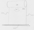
- FIG. 3 schematically shows a state in which the first intermediate film bulk sheet 3M1 is pulled out from the roll 3R of the intermediate film bulk sheet.
- the side 3S3 which is the end face of the intermediate film bulk sheet 3M1 (rectangular in plan view) in the pull-out direction is seen, the two main surfaces of the bulk sheet 3M1 are non-parallel, so that an angle occurs.
- the profile of the thickness in the drawing direction of the intermediate film bulk sheet 3M1 from the roll 3R is constant.
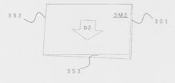
- FIG. 4 schematically shows the second intermediate film bulk sheet 3M2.
- the second interlayer film base sheet 3M2 the one cut out from the first interlayer film base sheet 3M1 extracted from the roll 3R may be applied.
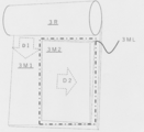
- FIG. 5 shows an intermediate film bulk material obtained by overlapping the first intermediate film bulk material sheet and the second intermediate film bulk material sheet so that the thickness profiles of both sheets are constant in the same direction. It is a figure showing sheet
- the laminated glass 1 is disposed between a curved first glass plate 21 having a trapezoidal or rectangular shape, a second glass plate 22 having the same shape as the first glass plate, and the first and second glass plates.
- 1 is a laminated glass 1 for a front window of a vehicle 100 including an intermediate film 3.
- the first glass plate 21 is disposed on the outdoor side
- the second glass plate 22 is disposed on the indoor side.
- the imaging unit 52 of the image projected from the imaging device 51 incorporated into the dashboard 4 on the driver's seat side is provided on the indoor side surface of the second glass plate 22. included.
- the intermediate film 3 has a wedge profile in which the thickness changes continuously in all directions of 360 ° when the vertical direction from the image forming part is 0 ° in observation from the inner surface of the vehicle, The thickness of the intermediate film based on the depression angle profile decreases continuously from the upper side 1U side to the lower side 1B side, and continuously in the horizontal direction from the side 1D on the driver's seat side to the side 1A on the passenger seat side Decrease.
- FIG. 1 shows the case where the driver's seat of the vehicle body 100 is the right-hand seat, and when the driver's seat of the vehicle body 100 is the left-hand seat, each configuration shown in FIG. .
- the glass plates 21 and 22 are generally used as glass plates for vehicles, and are glass plates made of soda lime silicate glass as defined in ISO 16293-1 manufactured by the float method. It can be used, and colorless ones and colored ones are used.
- the glass plates 21 and 22 have a curved trapezoidal or rectangular shape, and include an upper side 1U, a side 1D of the driver's seat, a side 1A of the passenger seat, and a lower side 1B. Each side is a cut surface formed by cutting the glass plates 21 and 22 from a glass plate larger than each glass plate, and the cut surface may be subjected to grinding or polishing.
- the curved glass plates 21 and 22 are obtained by a forming method by self-weight bending, a press forming method, or the like in which a predetermined large-scaled flat plate glass plate is heated to near the softening point to form it.
- the thickness of each glass plate may be appropriately selected, for example, in the range of 0.4 mm to 4 mm.
- glass plates 21 and 22 include plastic glass made of polyethylene terephthalate resin, polycarbonate resin, polycarbonate resin, polyvinyl chloride resin, polyethylene resin and the like.
- the intermediate film 3 is made of a thermoplastic polymer material, and as the polymer material, cycloolefin polymer (COP), polyurethane (PUR), ethylene vinyl acetate (EVA), polyvinyl butyral (PVB), etc. can be used. Particular preference is given to using PVB.
- the refractive index of the intermediate film 3 in the visible light region is preferably equivalent to that of the glass plates 21 and 22.
- the intermediate film 3 of the first laminated glass 1 is preferably provided by being cut out from an intermediate film bulk sheet stack 3ML having a depression angle profile in all directions.
- the intermediate film base sheet laminate 3ML can be obtained by laminating a first intermediate film base sheet 3M1 and a second intermediate film base sheet 3M2, as shown in FIG.
- the intermediate film base sheet 3M1 has non-parallel main surfaces of the intermediate film base sheet and a constant thickness profile in the pull-out direction of the roll 3R.
- a direction in which the thickness profile is constant (indicated by a broken arrow in FIG. 3) is taken as a direction D1. Since both main surfaces of the intermediate film base sheet are non-parallel, the thickness decreases continuously from the side 3S1 of the intermediate film base sheet 3M toward the other side 3S2.
- the angle of the direction indicated by the two solid arrows in the side 3S3 shown in the lower part of FIG. 3 is the largest angle of depression in this body sheet.
- the second intermediate film base sheet 3M2 may be cut out of the intermediate film base sheet 3M1 pulled out from the roll 3R.
- the second intermediate film base sheet 3M2 shown in FIG. 4 follows the thickness profile of the intermediate film base sheet 3S1.
- the direction in which the thickness profile is constant is denoted as a direction D2 (indicated by a broken arrow in FIG. 4).
- the second intermediate film base sheet 3M2 the one cut out from the first intermediate film base sheet 3M1 is exemplified, but a roll similar to the roll 3R may be prepared and cut out therefrom.
- the intermediate film is formed by overlapping the first intermediate film bulk sheet 3 M 1 and the second intermediate film bulk sheet 3 M 2 such that the directions D 1 and D 2 are not the same.
- a bulk sheet stack 3ML is obtained.
- the direction D1 and the direction D2 may not be the same, but the angle between the direction D1 and the direction D2 (the value on the included angle side is adopted) is 5 to 90 °, preferably 15 to It may be 75 °.
- the direction D2 may be arranged to be the same as the vertical direction from the lower side 1B to the upper side 1U, and the direction D1 may be arranged to be horizontal from the side 1D to the side 1A. .
- the direction D1 has an upper vertical direction of 0 ° from the image forming unit 52. Occasionally, it may be adjusted to any one angle of 60 ° to 87 °. In this case, the direction D2 is adjusted so that the angle formed between the direction D1 and the direction D2 is 5 to 90 °, preferably 15 to 75 °.
- the laminated glass 1 can be obtained. Further, in the intermediate film base sheets 3M1 and 3M2, there may be a zone in which the thickness profile becomes constant in the direction 31 from the side 3S1 or 3S2 side. When the intermediate film 3 includes the zone, the zone may be adjusted so that the zone does not include the imaging unit 52 in the laminated glass 1.
- the imaging unit 52 is formed on the indoor side surface of the laminated glass 1 (glass plate 22), and the virtual image 53 of the imaging 52 is observed by the observer 200 who is the driver.
- the suppression of the double image in the imaging unit 52 is important.
- the laminated glass 1 can be provided with a depression angle profile not only in the longitudinal direction but also in the horizontal direction and in all directions in the front window of the vehicle, so that the image can be formed regardless of the shape of the front window It is easy to reduce double images in the part 52.
- the intermediate film 3 has a depression angle of 0.1 mrad to 1.4 mrad in the 180 ° direction when the vertical direction from the image forming portion 52 is 0 °. Is preferred. If this angle is less than 0.1 mrad, the effect of double image suppression in the longitudinal direction of the laminated glass 1 tends to be small. On the other hand, in the case of more than 1.4 mrad, the thickness of the laminated glass on the upper side 1U side and the lower side is different, so that the efficiency at the time of assembling the laminated glass 1 to the vehicle body tends to decrease. Taking these into consideration, the depression angle may be 0.3 mrad to 1.2 mrad.
- a depression angle in the horizontal direction from the driver's seat side to the front passenger's seat side is 0.1 mrad to 0.6 mrad. If this angle is less than 0.1 mrad, the effect of double image suppression in the longitudinal direction of the laminated glass 1 tends to be small. On the other hand, in the case of more than 0.6 mrad, the double image suppression effect is too large, and it may be difficult to overlap and display the reflection image on the indoor side and the reflection image on the outdoor side. Taking these into consideration, the depression angle may be 0.2 mrad to 0.5 mrad. Furthermore, in the laminated film 1, the thickness of the intermediate film 3 may be 0.8 mm to 2.2 mm in a region where the maximum thickness is obtained.
- Step A A long intermediate film body sheet having a depression angle profile in which the thickness is continuously reduced in the direction from one side 3S1 to the opposite side 3S2, and both main surfaces of the intermediate film body sheet are Preparing a first intermediate film bulk sheet 3M1 which is non-parallel and whose thickness profile in one direction (direction D1) is constant, B1.
- a long intermediate film body sheet having a depression angle profile in which the thickness is continuously reduced in the direction from one side 3S1 to the opposite side 3S2, and both main surfaces of the intermediate film body sheet are Preparing a second intermediate film bulk sheet 3M2 which is non-parallel and whose thickness profile in one direction (direction D2) is constant, B2
- the first interlayer sheet precursor sheet 3M1 and the second interlayer sheet precursor sheet 3M2 are laminated so that the thickness profiles of the both are not constant (directions D1 and D2) so as not to be the same.
- step B3 Forming a body sheet laminate 3ML, step B3; Preparing a trapezoidal or rectangular intermediate film 3 cut out from the intermediate film base sheet stack 4ML; A process D may be provided, in which the intermediate film 3 is sandwiched between the first glass plate 21 and the second glass plate 22.
- first intermediate film base sheet 3M1, the second intermediate film base sheet 3M2, and the intermediate film base sheet laminate 3ML may be stretched to adjust the wrinkle profile of the base sheet.
- the first glass plates 21 and 22 and the intermediate film 3 are thermocompression bonded, for example, a laminate of the first glass plate 21 and the intermediate film 3 and the second glass plate 22 is 1.0.
- the laminated glass 1 can be manufactured by holding at 100 to 150 ° C. for 15 to 60 minutes while pressing at 1.5 to 1.5 MPa. Before thermocompression bonding, the intermediate film 3 and the glass plates 21 and 22 may be degassed.
- the second and third laminated glass 1 will be described in detail.
- at least one selected from the group consisting of the first glass plate and the second glass plate has a depression angle profile in which the thickness decreases continuously from one side to the opposite side.
- a glass plate hereinafter referred to as "glaze glass plate" which is non-parallel and whose thickness profile in one direction is constant is used.
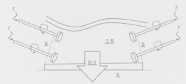
- FIG. 6 is a view schematically showing the main part of the state of molding of a glass substrate when a glazed glass plate is obtained by the float method.
- a molten glass base 2R is flowed over a molten metal bath 6 made of molten tin or the like, and a plurality of rolls 7 disposed on both wings of the bath 6 are rotated in the direction of dotted arrows to 2R molding is done.
- the glass substrate 2R flows in the direction of the arrow D3 directed downward on the bath 6.
- a glass plate in which the thickness of the glass substrate fluctuates in the width direction of the glass substrate 2R can be obtained.
- a glass plate having a profile in which the thickness continuously decreases, and a concave profile in which the central thickness in the width direction of the glass substrate 2R becomes the minimum thickness It is possible to obtain a glass plate having such a plate or the like having a convex profile such that the thickness at the center in the width direction of the glass base 2R becomes maximum.
- the second laminated glass 1 will be described with reference to FIGS. 1 and 2.
- the second laminated glass 1 is disposed between the curved first glass plate 21 having a trapezoidal or rectangular shape, the second glass plate 22 having the same shape as the first glass plate, and the first and second glass plates.
- a laminated glass 1 for a front window of a vehicle comprising: In the state where the laminated glass 1 is incorporated into the vehicle body 100, the indoor side surface of the laminated glass includes an imaging unit 52 of an image projected from the imaging device 51 incorporated into the dashboard 4 on the driver's seat side.
- the laminated glass 1 is provided with a wedge profile in which the thickness changes continuously in all directions of 360 ° when the vertical direction from the image forming part is 0 ° in observation from the inner surface of the vehicle, and the dip angle
- the thickness of laminated glass based on the profile decreases continuously from the upper side 1U side to the lower side 1B side, and continuously decreases in the horizontal direction from the side 1D on the driver's seat side to the side 1A on the passenger seat side
- At least one selected from the group consisting of the first glass plate 21 and the second glass plate 22 is a glazed glass plate, and the thickness is in the direction from the side on the side of the driver's seat to the side on the side of the passenger's seat.
- the intermediate film 3 has a depression angle profile whose thickness continuously decreases from the upper side to the lower side.
- the direction in which the thickness profile is constant is the direction D3, and in the intermediate film 3, the direction in which the thickness profile is constant is the direction D1.
- the glazed glass plate and the intermediate film 3 are stacked such that the direction D1 and the direction D3 are in different directions.
- the angle formed between the direction D1 and the direction D3 (the value on the included angle side is adopted) may be 5 to 90 °, preferably 15 to 75 °.
- the direction D3 of the glazed glass plate is arranged to be the same as the vertical direction from the lower side 1B to the upper side 1U, and the direction D1 of the intermediate film 3 is arranged so as to be the horizontal direction from the side 1D to the side 1A.
- the direction D3 is adjusted such that the angle between the direction D1 and the direction D3 is 5 to 90 °, preferably 15 to 75 °.
- the direction D3 is the flow direction of the glass substrate when the glass sheet is manufactured by the float method, micro streaks may occur in the surface layer of the glass sheet along the direction. Since the driver 200 has many opportunities to swing the neck left and right, when the direction D3 is disposed in the horizontal direction from the side 1D to the side 1A, the minute streaks are visually recognized by the driver 200 There is. When this is taken into consideration, it is preferable that the direction D3 of the glazed glass plate is arranged to be a direction of 0 ° in the upper vertical direction from the image forming portion 52 in the laminated glass including the grazing angle glass plate. The second laminated glass described above is preferable because it easily achieves this configuration. The grazing angle glass plate may be applied to either the first glass plate 21 or the second glass plate 22, or may be applied to both.
- the depression angle in the 180 ° direction is 0.1 mrad to 1.4 mrad when the vertical direction from the image forming portion is 0 ° in observation from the inner surface of the vehicle . If this angle is less than 0.1 mrad, the effect of double image suppression in the longitudinal direction of the laminated glass 1 tends to be small. On the other hand, in the case of more than 1.4 mrad, the thickness of the laminated glass on the upper side 1U side and the lower side is different, so that the efficiency at the time of assembling the laminated glass 1 to the vehicle body tends to decrease. Taking these into consideration, the depression angle may be 0.3 mrad to 1.2 mrad. Furthermore, in the laminated film 1, the thickness of the intermediate film 3 may be 0.8 mm to 2.2 mm in a region where the maximum thickness is obtained.
- a depression angle in the horizontal direction from the driver's seat side to the front passenger's seat side is 0.1 mrad to 0.6 mrad. If this angle is less than 0.1 mrad, the effect of double image suppression in the longitudinal direction of the laminated glass 1 tends to be small. On the other hand, in the case of more than 0.6 mrad, the double image suppression effect is too large, and it may be difficult to overlap and display the reflection image on the indoor side and the reflection image on the outdoor side. Taking these into consideration, the depression angle may be 0.2 mrad to 0.5 mrad.
- the third laminated glass 1 is a curved trapezoidal or rectangular first glass plate 21, a second glass plate 22 having the same shape as the first glass plate, the first and second glass plates 21, 22 is a laminated glass 1 for a front window of a vehicle, comprising an intermediate film 3 disposed between 22;
- the indoor side surface of the laminated glass 1 includes an imaging unit 52 of an image projected from an imaging device incorporated into the dashboard 4 on the driver's seat side.
- the laminated glass 1 is provided with a wedge profile in which the thickness changes continuously in all directions of 360 ° when the vertical direction from the image forming part is 0 ° in observation from the inner surface of the vehicle, and the dip angle
- the thickness of the laminated glass 1 based on the profile decreases continuously from the upper side to the lower side, and decreases continuously from the driver's seat side to the passenger side.
- At least one selected from the group consisting of the first glass plate 21 and the second glass plate 22 is a glazed glass plate, and a depression angle profile in which the thickness decreases continuously from the upper side 1U to the lower side 1B.
- Have The intermediate film 3 has a depression angle profile in which the thickness continuously decreases in the direction from the side 1D on the driver's seat side to the side 1A on the front passenger's seat side.
- the direction in which the thickness profile is constant is the direction D3, and in the intermediate film 3, the direction in which the thickness profile is constant is the direction D1.
- the glazed glass plate and the intermediate film 3 are stacked such that the direction D1 and the direction D3 are in different directions.
- the angle formed between the direction D1 and the direction D3 (the value on the included angle side is adopted) may be 5 to 90 °, preferably 15 to 75 °.
- the third laminated glass 1 has the arrangement of the direction D1 and the direction D3 interchanged with the second laminated glass 1.
- the direction D1 of the intermediate film 3 is arranged to be the same as the vertical direction from the lower side 1B to the upper side 1U, and the direction D3 of the glazed glass plate is arranged so as to be the horizontal direction from the side 1D to the side 1A.
- the direction D1 is adjusted such that the angle between the direction D1 and the direction D3 is 5 to 90 °, preferably 15 to 75 °.
- the depression angle in the 180 ° direction is 0.1 mrad to 1.4 mrad when the vertical direction from the image forming portion is 0 ° in observation from the inner surface of the vehicle . If this angle is less than 0.1 mrad, the effect of double image suppression in the longitudinal direction of the laminated glass 1 tends to be small. On the other hand, in the case of more than 1.4 mrad, the thickness of the laminated glass on the upper side 1U side and the lower side is different, so that the efficiency at the time of assembling the laminated glass 1 to the vehicle body tends to decrease. Taking these into consideration, the depression angle may be 0.3 mrad to 1.2 mrad. Furthermore, in the laminated film 1, the thickness of the intermediate film 3 may be 0.8 mm to 2.2 mm in a region where the maximum thickness is obtained.
- a depression angle in the horizontal direction from the driver's seat side to the front passenger's seat side is 0.1 mrad to 0.6 mrad. If this angle is less than 0.1 mrad, the effect of double image suppression in the longitudinal direction of the laminated glass 1 tends to be small. On the other hand, in the case of more than 0.6 mrad, the double image suppression effect is too large, and it may be difficult to overlap and display the reflection image on the indoor side and the reflection image on the outdoor side. Taking these into consideration, the depression angle may be 0.2 mrad to 0.5 mrad.
- a preferred method of manufacturing the second and third laminated glass 1 is to prepare a curved, trapezoidal or rectangular first glass plate 21 and a second glass plate 22 having the same shape as the first glass plate.
- Process A A long intermediate film body sheet 3M1 has a depression angle profile in which the thickness decreases continuously from one side to the opposite side, and both main surfaces of the intermediate film body sheet M1 are Preparing a first non-parallel, first intermediate film sheet 3M1 having a uniform thickness profile in one direction, B1.
- Another preferred method of manufacturing the second and third laminated glass 1 is a curved trapezoidal or rectangular first glass plate 21 and a second glass plate of the same shape as the first glass plate 22.
- a long intermediate film body sheet 3M1 has a depression angle profile in which the thickness decreases continuously from one side to the opposite side, and both main surfaces of the intermediate film body sheet are Preparing a first interlayer film precursor sheet 3M1 which is non-parallel and in which the thickness profile in one direction is constant, B1.
- At least one selected from the group consisting of the first glass plate and the second glass plate has a depression angle profile in which the thickness decreases continuously from one side to the opposite side, and a glass plate Both major surfaces are non-parallel, and the thickness profile in one direction is constant, The direction in which the thickness profile of the first interlayer sheet material sheet is constant is different from the direction in which the thickness profile of the glass sheet having the depression angle profile is constant.
- the first glass plates 21 and 22 and the intermediate film 3 are thermocompression bonded, for example, a laminate of the first glass plate 21 and the intermediate film 3 and the second glass plate 22 is 1.0.
- the laminated glass 1 can be manufactured by holding at 100 to 150 ° C. for 15 to 60 minutes while pressing at 1.5 to 1.5 MPa. Before thermocompression bonding, the intermediate film 3 and the glass plates 21 and 22 may be degassed.
Landscapes
- Physics & Mathematics (AREA)
- General Physics & Mathematics (AREA)
- Optics & Photonics (AREA)
- Joining Of Glass To Other Materials (AREA)
- Instrument Panels (AREA)
Abstract
【課題】窓の縦方向の曲率だけでなく、水平方向の曲率の影響によるHUDの二重像を低減できる楔角プロファイルを有する中間膜を用いた合せガラスを提供する。 【解決手段】湾曲した、台形状又は矩形状の第一ガラス板と、前記第一ガラス板と同形状の第二ガラス板と、前記第一、第二ガラス板の間に配置される中間膜とを備える、車両のフロント窓用の合せガラスであって、 前記合せガラスが車体へ組み込まれた状態において、前記合せガラスの室内側面には、運転席側のダッシュボードに組み込まれた映像装置から投射された像の結像部が含まれ、 前記中間膜は、車内面からの観測において、前記結像部から上縦方向を0°としたときに、360°の全方向に連続的に厚みが変化する楔プロファイルを備え、前記楔角プロファイル基づく中間膜の厚みが、上辺側から下辺側にかけて連続的に減少し、かつ、運転者席側から助手席側水平方向に連続的に減少すること.
Description
本発明は、ヘッドアップディスプレイ(HUD)の表示部材として適用される、車両用フロント窓用の湾曲化した合せガラスに関する。
HUDの表示部材として適用される、車両用フロント窓用の湾曲化した台形状又は矩形状の合せガラスの中間膜には、前記合せガラスの形状と概略同一の形状で、前記一つの辺から対向する辺に向かって連続的に(線形に)厚みが変化する中間膜、所謂、楔角プロファイルを有する中間膜が使用されている。また、楔角プロファイルを有する中間膜以外に、楔角プロファイルを有するガラス板の使用も提案されている(例えば、特許文献7~9)。前記楔角プロファイルは、前記合せガラスが車両に組み込まれたときに、前記合せガラスの上辺から下辺側へ縦方向に厚みが減少するように、そして、合せガラスの水平方向には厚みが一定となるように、前記合せガラス内に一体成形される。
前記表示部材に投射する映像装置は、運転席前方のダッシュボート内に備えつけられているので、前記映像装置から投射された像の結像部は、前記合せガラスの室内側ガラス面に投影される。その際、前記合せガラスの室外側のガラス表面には、前記結像部よりも上方に前記結像部の反射像が投影される(光学系の説明については、例えば、特許文献1、2を参照されたい)。前記合せガラスの面は、運転者に向かって傾いているので、結果、運転者には、下辺から上辺側への縦方向に二重像が視認されやすいものとなる。車両では、映像は合せガラスの下方から室内側ガラス面に投射されることになるので、前記合せガラスによって、二重像の低減が図られてきた(例えば、特許文献3~5)。
しかしながら、近年では、車両のデザインが多種多様化し、車両用フロント窓にあっては、水平方向にも曲率の大きな窓も増えてきていることから、特許文献6で示唆されるように、二重像の現れ方に、水平方向の曲率が影響するようになってきた。そして、特許文献6は、合せガラスの中間膜の水平方向にも楔角プロファイルを設ける必要性を提案し、中間膜の一つのセクションに垂直方向及び水平方向に連続する非線形の楔角プロファイルを有する中間膜を備えた合せガラスにて、二重像の現れ方に対して水平方向の影響の低減を図っている。
HUDの表示部材として適用される、車両用フロント窓用の湾曲化した合せガラスでの二重像の低減にあっては、前途したように、水平方向のガラスの曲率の影響も考慮する必要が出てきている。特許文献6で提案されているような、中間膜の活用で、二重像の現れ方に対して水平方向の影響の低減を図れるとは思われる。
しかしながら、合せガラスの工業的な生産においては、前記中間膜は、ロールでの提供となる。そのため、楔角プロファイルは、中間膜原体シートのロールの側辺から側辺(円柱体の上面から底面)方向に厚みが連続的に減少し、ロールの引き出し方向は厚みが一定とならざるを得ない(尚、従来では、その厚みの一定の方向は、合せガラスにおいては、水平方向に位置するように配置されてきた)。特許文献4で提案されているような中間膜を製造するためには、ロールから、前記中間膜原体シートを短冊状に切り取り、さらなる楔角プロファイルを有するように、中間膜をプレス成型等で加工する必要がある。そのような加工は、合せガラスのコスト高の要因となるだけでなく、加工の煩雑さに起因する、中間膜面の加工精度の低下のリスクを高める。
本発明は、車両用フロント窓を表示部材とした、HUDに関し、窓の縦方向の曲率だけでなく、水平方向の曲率の影響によるHUDの二重像を低減できる楔角プロファイルを有する中間膜を用いた合せガラスを提供することを課題とする。
本発明の合せガラスは、湾曲した、台形状又は矩形状の第一ガラス板と、前記第一ガラス板と同形状の第二ガラス板と、前記第一、第二ガラス板の間に配置される中間膜とを備える、車両のフロント窓用の合せガラスであって、
前記合せガラスが車体へ組み込まれた状態において、前記合せガラスの室内側面には、運転席側のダッシュボードに組み込まれた映像装置から投射された像の結像部が含まれ、
前記合せガラスは、車内からの観測において、前記結像部から上縦方向を0°としたときに、360°の全方向に連続的に厚みが変化する楔プロファイルを備え、前記楔角プロファイル基づく合せガラスの厚みが、上辺側から下辺側にかけて連続的に減少し、かつ、運転者席側から助手席側水平方向に連続的に減少することを特徴とする。
前記合せガラスが車体へ組み込まれた状態において、前記合せガラスの室内側面には、運転席側のダッシュボードに組み込まれた映像装置から投射された像の結像部が含まれ、
前記合せガラスは、車内からの観測において、前記結像部から上縦方向を0°としたときに、360°の全方向に連続的に厚みが変化する楔プロファイルを備え、前記楔角プロファイル基づく合せガラスの厚みが、上辺側から下辺側にかけて連続的に減少し、かつ、運転者席側から助手席側水平方向に連続的に減少することを特徴とする。
この合せガラスは、前記合せガラスの縦方向と水平方向に楔角プロファイルを備え、前記楔角プロファイル基づく合せガラスの厚みが、上辺側から下辺側にかけて連続的に減少し、かつ、運転者席側から助手席側方向に連続的に減少する構造である。そのため、これら方向での二重像の低減を図ることができる。
そして、好適な合せガラス(第一の合せガラス)は、湾曲した、台形状又は矩形状の第一ガラス板と、前記第一ガラス板と同形状の第二ガラス板と、前記第一、第二ガラス板の間に配置される中間膜とを備える、車両のフロント窓用の合せガラスであって、
前記合せガラスが車体へ組み込まれた状態において、前記合せガラスの室内側面には、運転席側のダッシュボードに組み込まれた映像装置から投射された像の結像部が含まれ、
前記中間膜は、車内からの観測において、前記結像部から上縦方向を0°としたときに、360°の全方向に連続的に厚みが変化する楔プロファイルを備え、前記楔角プロファイル基づく中間膜の厚みが、上辺側から下辺側にかけて連続的に減少し、かつ、運転者席側から助手席側水平方向に連続的に減少することを特徴とする。
前記合せガラスが車体へ組み込まれた状態において、前記合せガラスの室内側面には、運転席側のダッシュボードに組み込まれた映像装置から投射された像の結像部が含まれ、
前記中間膜は、車内からの観測において、前記結像部から上縦方向を0°としたときに、360°の全方向に連続的に厚みが変化する楔プロファイルを備え、前記楔角プロファイル基づく中間膜の厚みが、上辺側から下辺側にかけて連続的に減少し、かつ、運転者席側から助手席側水平方向に連続的に減少することを特徴とする。
この合せガラスは、前記中間膜を、前記合せガラスの縦方向と水平方向に楔角プロファイルを備え、前記楔角プロファイル基づく中間膜の厚みが、上辺側から下辺側にかけて連続的に減少し、かつ、運転者席側から助手席側方向に連続的に減少する構造である。そのため、これら方向での二重像の低減を図ることができる。
また、別の好適な合せガラス(第二の合せガラス)は、湾曲した、台形状又は矩形状の第一ガラス板と、前記第一ガラス板と同形状の第二ガラス板と、前記第一、第二ガラス板の間に配置される中間膜とを備える、車両のフロント窓用の合せガラスであって、
前記合せガラスが車体へ組み込まれた状態において、前記合せガラスの室内側面には、運転席側のダッシュボードに組み込まれた映像装置から投射された像の結像部が含まれ、
前記合せガラスは、車内からの観測において、前記結像部から上縦方向を0°としたときに、360°の全方向に連続的に厚みが変化する楔プロファイルを備え、前記楔角プロファイル基づく合せガラスの厚みが、上辺側から下辺側にかけて連続的に減少し、かつ、運転者席側から助手席側水平方向に連続的に減少し、
前記第一ガラス板と、前記第二ガラス板とからなる群から選ばれる少なくとも一つは、運手席側の側辺から助手席側の側辺方向に厚みが連続的に減少する楔角プロファイルを有し、
前記中間膜は、上辺側から下辺側にかけて厚みが連続的に減少する楔角プロファイルを有することを特徴とする。
前記合せガラスが車体へ組み込まれた状態において、前記合せガラスの室内側面には、運転席側のダッシュボードに組み込まれた映像装置から投射された像の結像部が含まれ、
前記合せガラスは、車内からの観測において、前記結像部から上縦方向を0°としたときに、360°の全方向に連続的に厚みが変化する楔プロファイルを備え、前記楔角プロファイル基づく合せガラスの厚みが、上辺側から下辺側にかけて連続的に減少し、かつ、運転者席側から助手席側水平方向に連続的に減少し、
前記第一ガラス板と、前記第二ガラス板とからなる群から選ばれる少なくとも一つは、運手席側の側辺から助手席側の側辺方向に厚みが連続的に減少する楔角プロファイルを有し、
前記中間膜は、上辺側から下辺側にかけて厚みが連続的に減少する楔角プロファイルを有することを特徴とする。
この合せガラスは、前記中間膜とガラス板とで、前記合せガラスの縦方向と水平方向に楔角プロファイルを備えたものとしている。かくして、前記楔角プロファイル基づく合せガラスの厚みが、上辺側から下辺側にかけて連続的に減少し、かつ、運転者席側から助手席側方向に連続的に減少する構造となる。そのため、これら方向での二重像の低減を図ることができる。
さらに、別の好適な合せガラス(第三の合せガラス)は、湾曲した、台形状又は矩形状の第一ガラス板と、前記第一ガラス板と同形状の第二ガラス板と、前記第一、第二ガラス板の間に配置される中間膜とを備える、車両のフロント窓用の合せガラスであって、
前記合せガラスが車体へ組み込まれた状態において、前記合せガラスの室内側面には、運転席側のダッシュボードに組み込まれた映像装置から投射された像の結像部が含まれ、
前記合せガラスは、車内からの観測において、前記結像部から上縦方向を0°としたときに、360°の全方向に連続的に厚みが変化する楔プロファイルを備え、前記楔角プロファイル基づく合せガラスの厚みが、上辺側から下辺側にかけて連続的に減少し、かつ、運転者席側から助手席側水平方向に連続的に減少し、
前記第一ガラス板と、前記第二ガラス板とからなる群から選ばれる少なくとも一つは、上辺側から下辺側にかけて厚みが連続的に減少する楔角プロファイルを有し、
前記中間膜は、運転者席側の側辺から助手席側の側辺方向に厚みが連続的に減少する楔角プロファイルを有することを特徴とする。
前記合せガラスが車体へ組み込まれた状態において、前記合せガラスの室内側面には、運転席側のダッシュボードに組み込まれた映像装置から投射された像の結像部が含まれ、
前記合せガラスは、車内からの観測において、前記結像部から上縦方向を0°としたときに、360°の全方向に連続的に厚みが変化する楔プロファイルを備え、前記楔角プロファイル基づく合せガラスの厚みが、上辺側から下辺側にかけて連続的に減少し、かつ、運転者席側から助手席側水平方向に連続的に減少し、
前記第一ガラス板と、前記第二ガラス板とからなる群から選ばれる少なくとも一つは、上辺側から下辺側にかけて厚みが連続的に減少する楔角プロファイルを有し、
前記中間膜は、運転者席側の側辺から助手席側の側辺方向に厚みが連続的に減少する楔角プロファイルを有することを特徴とする。
この合せガラスは、前記中間膜とガラス板とで、前記合せガラスの縦方向と水平方向に楔角プロファイルを備えたものとしている。かくして、前記楔角プロファイル基づく合せガラスの厚みが、上辺側から下辺側にかけて連続的に減少し、かつ、運転者席側から助手席側方向に連続的に減少する構造となる。そのため、これら方向での二重像の低減を図ることができる。
本発明の車両フロント窓用の合せガラスをHUDの表示部材としたときには、像の二重像の現れ方に対して、縦方向だけでなく、水平方向の影響の低減を図れる。さらには、合せガラスの面内の全方向に楔角プロファイルを有するので、フロント窓の形状によらず、二重像の低減を図ることができる。
本発明の合せガラスを、図面を用いて説明する。図1は、フロント窓として車両に組み込まれた、本発明の合せガラス1を前記車体100の前方から観察したときの要部を説明する図である。そして、図2は、前記合せガラスに関し、図1のa-a’断面を見た上で、前記合せガラスを、HUDの表示部材とし、その表示部材と、前記表示部材に投射する映像装置51と、前記映像装置51から投射された像の結像部52と、観察者(運転手)200が視認する虚像53との関係を説明する図である。図3は、第一中間膜原体シート3M1が、中間膜原体シートのロール3Rから引き出された状態を模式的に表したものである。中間膜原体シート3M1(平面視においては長方形)の引き出し方向の端面となる側辺3S3を見たときに、原体シート3M1の両主面は非平行なので、角度が生じる。ロール3Rからの中間膜原体シート3M1の引き出し方向の厚みのプロファイルは一定である。
図4は、第二中間膜原体シート3M2を模式的に表したものである。第二中間膜原体シート3M2は、ロール3Rから引き出された第一中間膜原体シート3M1から切り出されたものが適用されてもよい。図5は、第一中間膜原体シートと、第二中間膜原体シートとが、両シートの厚みプロファイルが一定である方向が同じとならないように重ねることで得られた、中間膜原体シート積層体3ML(図5中では、1点鎖線で示されている)を表す図である。
前記合せガラス1は、湾曲した、台形状又は矩形状の第一ガラス板21と、前記第一ガラス板と同形状の第二ガラス板22と、前記第一、第二ガラス板の間に配置される中間膜3とを備える、車両100のフロント窓用の合せガラス1である。前記合せガラス1は、車体100への組み込まれた時において、前記第一ガラス板21は、室外側に配置され、前記第二ガラス板22は、室内側に配置されることになる。
また、車体100への組み込まれた合せガラス1では、第二ガラス板22の室内側面には、運転席側のダッシュボード4に組み込まれた映像装置51から投射された像の結像部52が含まれる。さらには、前記中間膜3は、車内面からの観測において、前記結像部から上縦方向を0°としたときに、360°の全方向に連続的に厚みが変化する楔プロファイルを備え、前記楔角プロファイル基づく中間膜の厚みが、上辺1U側から下辺1B側にかけて連続的に減少し、かつ、運転者席側の側辺1Dから助手席側の側辺1Aへと、水平方向に連続的に減少する。図1は、前記車体100の運転者席が右側シートの場合を示したもので、前記車体100の運転席が左側シートの場合は、図1に示した各構成は、左右反対の配置となる。
前記ガラス板21、22としては、車両用のガラス板として汎用されている、フロ-ト法で製造された、ISO16293-1で規定されているようなソーダ石灰ケイ酸塩ガラスからなるガラス板を使用でき、無色のもの、着色されたものが使用される。ガラス板21、22は、湾曲した台形状乃至矩形状のものであり、上辺1U、運転席の側辺1D、助手席側の側辺1A、下辺1Bを備える。各辺は、前記ガラス板21、22が、各ガラス板よりも大きなガラス板から切断されて形成された切断面であり、その切断面は、研削や研磨が施されていてもよい。湾曲化されたガラス板21、22は、所定の大きさい切り出された平板のガラス板を、軟化点付近まで加熱して、成形する、自重曲げによる成形法や、プレス成型法などによって得られる。各ガラス板の厚みとしては、例えば、0.4mm~4mmの範囲で適宜選定してもよい。
前記ガラス板21,22に使用される、その他の例としては、ポリエチレンテレフタレート樹脂、ポリカーボネート樹脂、ポリカーボネート樹脂、ポリ塩化ビニール樹脂、ポリエチレン樹脂等からなるプラスチックガラスが挙げられる。
前記中間膜3は、熱可塑性のポリマー材料からなり、そのポリマー材料として、シクロオレフィンポリマー(COP)、ポリウレタン(PUR)、エチレンビニルアセテート(EVA)、ポリビニルブチラール(PVB)などを使用することができ、特に好ましくはPVBを使用することができる。前記中間膜3の可視光領域での屈折率は、前記ガラス板21、22と同等なものとすることが好ましい。
次に第一の合せガラス1について詳述する。第一の合せガラス1の中間膜3は、全方向に楔角プロファイルを備える、中間膜原体シート積層体3MLから切り出されて提供されることが好ましい。前記中間膜原体シート積層体3MLは、図5に示すように、第一中間膜原体シート3M1と、第二中間膜原体シート3M2とを積層することで得られることができる。
中間膜原体シート3M1は、図3に示したように、中間膜原体シートの両主面は、非平行で、ロール3Rの引き出し方向の厚みプロファイルは一定である。この厚みプロファイルが一定となっている方向(図3中では、破線矢印で示されている)を方向D1とする。中間膜原体シートの両主面は、非平行なので、中間膜原体シート3Mの側辺3S1から、もう片方の側辺3S2に向かって連続的に厚みが減少するものとなる。図3の下方に示した側辺3S3部の2つの実線の矢印で示されている方向の角度が、この原体シートでは、楔角が最大のものとなる。
第二中間膜原体シート3M2は、前記ロール3Rから引き出された中間膜原体シート3M1から切り出されたものを適用してもよい。図4で表された第二中間膜原体シート3M2は、中間膜原体シート3S1の厚みプロファイルを踏襲している。第二中間膜原体シート3M2では、厚みプロファイルが一定となっている方向を、方向D2と表記する(図4中では、破線の矢印で示されている)。ここでは、第二中間膜原体シート3M2として、第一中間膜原体シート3M1から切り出されたものが例示されたが、前記ロール3Rと同様なロールを準備して、それから切り出してもよい。
図5で表したように、第一中間膜原体シート3M1と、第二中間膜原体シート3M2とを、方向D1と、方向D2との方向が同じとならないように重ねることで、中間膜原体シート積層体3MLが得られる。方向D1と、方向D2とは同じとならなければよいが、方向D1と方向D2とでなす角度(挟角側の値を採用するものとする)は、5~90°、好ましくは、15~75°としてもよい。また、前記方向D2を下辺1Bから上辺1Uへの縦方向と同じとなるように配置し、前記方向D1を、側辺1Dから、側辺1Aへの水平方向となるように配置してもよい。ここでの「縦方向と同じとなるように配置」、「水平方向となるように配置」された構造の他に、前記方向D1は、前記結像部52から上縦方向を0°としたときに、60°~87°のうちの任意の一角度に調整してもよい。この場合、方向D2は、方向D1と方向D2とでなす角度は、5~90°、好ましくは、15~75°となるように調整される。
中間膜原体シート積層体3MLを、前記中間膜3の材料とすることで、合せガラス1を得ることができる。また、中間膜原体シート3M1、3M2において、側辺3S1、又は3S2側から方向31の方向に、厚みのプロファイルが一定となる帯域があってもよい。中間膜3が、前記帯域を含むことになる場合、合せガラス1にて、前記帯域が結像部52を含むことがないように、調整されればよい。
前記合せガラス1を使用するHUDにおいては、ダッシュボート4に組み込まれた映像装置51から、映像は図2の実践の矢印で示したように上方向に投射される。そして、合せガラス1(ガラス板22)の室内側面に、結像部52が形成され、結像52の虚像53が運転手である観察者200に観察されるようになる。観察者200に視認される虚像の二重像の抑制は、結像部52での二重像の抑制が重要となる。
前記合せガラス1では、車両のフロント窓において、縦方向だけでなく、水平方向にも、そして、全方向に楔角プロファイルを備えたものとできるので、前記フロント窓の形状によらず、結像部52での二重像を低減させやすい。
前記合せガラス1において、前記中間膜3は、車内面からの観測において、前記結像部52から上縦方向を0°としたときに180°方向の楔角が、0.1mrad~1.4mradであることが好ましい。この角度が、0.1mrad未満の場合、合せガラス1の縦方向の二重像抑制の効果が小さくなりやすい。他方で、1.4mrad超の場合、上辺1U側と下辺側での合せガラスの厚みに差異が生じるため、合せガラス1を車体へ組み付ける際の効率が低下しやすい。これらを考慮すると、該楔角は、0.3mrad~1.2mradとしてもよい。
また、前記合せガラス1において、運転者席側から助手席側水平方向の楔角が、0.1mrad~0.6mradであることが好ましい。この角度が、0.1mrad未満の場合、合せガラス1の縦方向の二重像抑制の効果が小さくなりやすい。他方で、0.6mrad超の場合、二重像抑制の効果が大きくなり過ぎて、室内側の反射像と室外側の反射像を重ねて表示することが困難となることがある。これらを考慮すると、該楔角は、0.2mrad~0.5mradとしてもよい。さらには、合せガラス1において、中間膜3では、最大の厚みとなる領域では、その厚みは0.8mm~2.2mmとしてもよい。
前記第一の合せガラス1の製造方法としては、
湾曲した、台形状又は矩形状の第一ガラス板21と、前記第一ガラス板と同形状の第二ガラス板22とを準備する、工程Aと、
長尺状の中間膜原体シートであって、一方の側辺3S1から反対側辺3S2方向に厚みが連続的に減少する楔角プロファイルを有し、前記中間膜原体シートの両主面は、非平行で、一方向(方向D1)の厚みプロファイルが一定である第一中間膜原体シート3M1を準備する、工程B1と、
長尺状の中間膜原体シートであって、一方の側辺3S1から反対側辺3S2方向に厚みが連続的に減少する楔角プロファイルを有し、前記中間膜原体シートの両主面は、非平行で、一方向(方向D2)の厚みプロファイルが一定である第二中間膜原体シート3M2を準備する、工程B2と、
前記第一中間膜原体シート3M1と、前記第二中間膜原体シート3M2とを、双方の、厚みプロファイルが一定である(方向D1とD2)方向が同じとならないように張り合わせて中間膜原体シート積層体3MLを形成する、工程B3と、
前記中間膜原体シート積層体4MLから切り出された、台形状又は矩形状の中間膜3を準備する、工程Cと、
前記第一ガラス板21と、前記第二ガラス板22との間に、前記中間膜3を挟み込む、工程Dとを、備えるものとしてもよい。
湾曲した、台形状又は矩形状の第一ガラス板21と、前記第一ガラス板と同形状の第二ガラス板22とを準備する、工程Aと、
長尺状の中間膜原体シートであって、一方の側辺3S1から反対側辺3S2方向に厚みが連続的に減少する楔角プロファイルを有し、前記中間膜原体シートの両主面は、非平行で、一方向(方向D1)の厚みプロファイルが一定である第一中間膜原体シート3M1を準備する、工程B1と、
長尺状の中間膜原体シートであって、一方の側辺3S1から反対側辺3S2方向に厚みが連続的に減少する楔角プロファイルを有し、前記中間膜原体シートの両主面は、非平行で、一方向(方向D2)の厚みプロファイルが一定である第二中間膜原体シート3M2を準備する、工程B2と、
前記第一中間膜原体シート3M1と、前記第二中間膜原体シート3M2とを、双方の、厚みプロファイルが一定である(方向D1とD2)方向が同じとならないように張り合わせて中間膜原体シート積層体3MLを形成する、工程B3と、
前記中間膜原体シート積層体4MLから切り出された、台形状又は矩形状の中間膜3を準備する、工程Cと、
前記第一ガラス板21と、前記第二ガラス板22との間に、前記中間膜3を挟み込む、工程Dとを、備えるものとしてもよい。
また、第一の前記合せガラス1の他の態様の製造方法として、
台形状又は矩形状の第一ガラス板と、前記第一ガラス板21と同形状の第二ガラス板22とを準備する、工程Aと、
長尺状の中間膜原体シート3M1であって、一方の側辺3S1から反対側辺3S2方向に厚みが連続的に減少する楔角プロファイルを有し、前記中間膜原体シートの両主面は、非平行で、一方向(方向D1)の厚みプロファイルが一定である第一中間膜原体シートを準備する、工程B1と、
長尺状の中間膜原体シートであって、一方の側辺3S1から反対側辺3S2方向に厚みが連続的に減少する楔角プロファイルを有し、前記中間膜原体シートの両主面は、非平行で、一方向(方向D2)の厚みプロファイルが一定である第二中間膜原体シート3M2を準備する、工程B2と、
前記第一中間膜原体シート3M1と、前記第二中間膜原体シート3M2とを、双方の、厚みプロファイルが一定である方向(方向D1とD2)が同じとならないようにして張り合わせて中間膜原体シート積層体3MLを形成する、工程B3と、
前記第一ガラス板21と、前記第二ガラス板22との間に、前記中間膜原体シート積層体3MLを挟み込む、工程Eと、
前記第一ガラス板と、前記第二ガラス板との間に挟まれた前記中間膜原体シート積層体から、台形状又は矩形状の中間膜3Sを切り出す、工程Fと、
を備えるものとしてもよい。
台形状又は矩形状の第一ガラス板と、前記第一ガラス板21と同形状の第二ガラス板22とを準備する、工程Aと、
長尺状の中間膜原体シート3M1であって、一方の側辺3S1から反対側辺3S2方向に厚みが連続的に減少する楔角プロファイルを有し、前記中間膜原体シートの両主面は、非平行で、一方向(方向D1)の厚みプロファイルが一定である第一中間膜原体シートを準備する、工程B1と、
長尺状の中間膜原体シートであって、一方の側辺3S1から反対側辺3S2方向に厚みが連続的に減少する楔角プロファイルを有し、前記中間膜原体シートの両主面は、非平行で、一方向(方向D2)の厚みプロファイルが一定である第二中間膜原体シート3M2を準備する、工程B2と、
前記第一中間膜原体シート3M1と、前記第二中間膜原体シート3M2とを、双方の、厚みプロファイルが一定である方向(方向D1とD2)が同じとならないようにして張り合わせて中間膜原体シート積層体3MLを形成する、工程B3と、
前記第一ガラス板21と、前記第二ガラス板22との間に、前記中間膜原体シート積層体3MLを挟み込む、工程Eと、
前記第一ガラス板と、前記第二ガラス板との間に挟まれた前記中間膜原体シート積層体から、台形状又は矩形状の中間膜3Sを切り出す、工程Fと、
を備えるものとしてもよい。
また、第一中間膜原体シート3M1や、第二中間膜原体シート3M2や、中間膜原体シート積層体3MLを、延伸加工し、原体シートの楔プロファイルの調整を行ってもよい。
前記工程Cの後、第一ガラス板21、22と、中間膜3とを熱圧着する、例えば、第一ガラス板21と、中間膜3、第二ガラス板22との積層体を1.0~1.5MPaで加圧しながら、100~150℃で15~60分保持することで合せガラス1を製造することができる。熱圧着する前に、中間膜3と、各ガラス板21、22との間を脱気していてもよい。
次に第二の、第三の合せガラス1について詳述する。これら合せガラスでは、前記第一ガラス板と、前記第二ガラス板とからなる群から選ばれる少なくとも一つは、一方の側辺から反対側辺方向に厚みが連続的に減少する楔角プロファイルを有し、ガラス板の両主面は、非平行で、一方向の厚みプロファイルが一定である、ガラス板(以降、「楔ガラス板」と表記する)が使用される。
前記楔ガラス板は、ガラス板をフロート法で製造する際の条件を工夫することで得られる。図6は、フロート法で、楔ガラス板を得る時のガラス素地の成形の様子の要部を模式的に示す図である。フロート法では、溶融錫等からなる溶融金属浴6上に溶融されたガラス素地2Rが流され、前記浴6の両翼に配置された複数のロール7を点線矢印の方向に回転させて、ガラス素地2Rの成形がなされる。ガラス素地2Rは、浴6上を下方に向いた矢印D3の方向に流れていく。ロール7が回転するときの周速度を調整することで、ガラス素地の厚みがガラス素地2Rの幅方向で変動するガラス板が得られる。例えば、図6に示したような右側から左側にかけて、厚みが連続的に減少するプロファイルを有するガラス板、ガラス素地2Rの幅方向の中央の厚みが最小の厚みとなるような凹形状のプロファイルを有するガラス板、ガラス素地2Rの幅方向の中央の厚みが最大の厚みとなるような凸形状のプロファイルを有する板などを得ることができる。
第二の合せガラス1を、図1、図2を参照して説明する。第二の合せガラス1は、湾曲した、台形状又は矩形状の第一ガラス板21と、前記第一ガラス板と同形状の第二ガラス板22と、前記第一、第二ガラス板の間に配置される中間膜3とを備える、車両のフロント窓用の合せガラス1であって、
前記合せガラス1が車体100へ組み込まれた状態において、前記合せガラスの室内側面には、運転席側のダッシュボード4に組み込まれた映像装置51から投射された像の結像部52が含まれ、
前記合せガラス1は、車内面からの観測において、前記結像部から上縦方向を0°としたときに、360°の全方向に連続的に厚みが変化する楔プロファイルを備え、前記楔角プロファイル基づく合せガラスの厚みが、上辺1U側から下辺1B側にかけて連続的に減少し、かつ、運転者席側の側辺1Dから助手席側の側辺1Aへと、水平方向に連続的に減少し、
前記第一ガラス板21と、前記第二ガラス板22とからなる群から選ばれる少なくとも一つは、楔ガラス板であり、運手席側の側辺から助手席側の側辺方向に厚みが連続的に減少する楔角プロファイルを有し、
前記中間膜3は、上辺側から下辺側にかけて厚みが連続的に減少する楔角プロファイルを有するものである。
前記合せガラス1が車体100へ組み込まれた状態において、前記合せガラスの室内側面には、運転席側のダッシュボード4に組み込まれた映像装置51から投射された像の結像部52が含まれ、
前記合せガラス1は、車内面からの観測において、前記結像部から上縦方向を0°としたときに、360°の全方向に連続的に厚みが変化する楔プロファイルを備え、前記楔角プロファイル基づく合せガラスの厚みが、上辺1U側から下辺1B側にかけて連続的に減少し、かつ、運転者席側の側辺1Dから助手席側の側辺1Aへと、水平方向に連続的に減少し、
前記第一ガラス板21と、前記第二ガラス板22とからなる群から選ばれる少なくとも一つは、楔ガラス板であり、運手席側の側辺から助手席側の側辺方向に厚みが連続的に減少する楔角プロファイルを有し、
前記中間膜3は、上辺側から下辺側にかけて厚みが連続的に減少する楔角プロファイルを有するものである。
楔ガラス板では、厚みプロファイルが一定となる方向は方向D3となり、中間膜3では、厚みプロファイルが一定となる方向は方向D1となる。楔ガラス板と、中間膜3とは、方向D1と、方向D3とが、異なる方向となるように積層される。方向D1と方向D3とでなす角度(挟角側の値を採用するものとする)は、5~90°、好ましくは、15~75°としてもよい。
楔ガラス板の方向D3を下辺1Bから上辺1Uへの縦方向と同じとなるように配置し、中間膜3の方向D1を、側辺1Dから、側辺1Aへの水平方向となるように配置してもよい。ここでの「縦方向と同じとなるように配置」、「水平方向となるように配置」された構造の他に、前記方向D1は、前記結像部52から上縦方向を0°としたときに、60°~87°のうちの任意の一角度に調整してもよい。方向D3は、方向D1と方向D3とでなす角度は、5~90°、好ましくは、15~75°となるように調整される。
前記方向D3は、ガラス板がフロート法で製造される際に、ガラス素地の流れる方向であるので、ガラス板の表層には、その方向に沿った微小な筋が生じることがある。運転者200は、首を左右に振る機会が多い事から、方向D3が、側辺1Dから側辺1Aへの水平方向に配置される場合、その微小な筋が運転者200に視認されることがある。これを考慮した場合、楔角ガラス板を含む合せガラスでは、楔ガラス板の方向D3は、前記結像部52から上縦方向0°の方向となるように配置されることが好ましい。前記の第二の合せガラスは、この構成を達成しやすく、好ましい。尚、楔角ガラス板は、第一ガラス板21、第二ガラス板22のいずれかに適用されてもよいし、両方に適用されてもよい。
第二の合せガラス1において、車内面からの観測において、前記結像部から上縦方向を0°としたときに180°方向の楔角が、0.1mrad~1.4mradであることが好ましい。この角度が、0.1mrad未満の場合、合せガラス1の縦方向の二重像抑制の効果が小さくなりやすい。他方で、1.4mrad超の場合、上辺1U側と下辺側での合せガラスの厚みに差異が生じるため、合せガラス1を車体へ組み付ける際の効率が低下しやすい。これらを考慮すると、該楔角は、0.3mrad~1.2mradとしてもよい。さらには、合せガラス1において、中間膜3では、最大の厚みとなる領域では、その厚みは0.8mm~2.2mmとしてもよい。
また、前記合せガラス1において、運転者席側から助手席側水平方向の楔角が、0.1mrad~0.6mradであることが好ましい。この角度が、0.1mrad未満の場合、合せガラス1の縦方向の二重像抑制の効果が小さくなりやすい。他方で、0.6mrad超の場合、二重像抑制の効果が大きくなり過ぎて、室内側の反射像と室外側の反射像を重ねて表示することが困難となることがある。これらを考慮すると、該楔角は、0.2mrad~0.5mradとしてもよい。
次に、第三の合せガラス1を、図1、図2を参照して説明する。第三の合せガラス1は、湾曲した、台形状又は矩形状の第一ガラス板21と、前記第一ガラス板と同形状の第二ガラス板22と、前記第一、第二ガラス板21、22の間に配置される中間膜3とを備える、車両のフロント窓用の合せガラス1であって、
前記合せガラス1が車体100へ組み込まれた状態において、前記合せガラス1の室内側面には、運転席側のダッシュボード4に組み込まれた映像装置から投射された像の結像部52が含まれ、
前記合せガラス1は、車内面からの観測において、前記結像部から上縦方向を0°としたときに、360°の全方向に連続的に厚みが変化する楔プロファイルを備え、前記楔角プロファイル基づく合せガラス1の厚みが、上辺側から下辺側にかけて連続的に減少し、かつ、運転者席側から助手席側水平方向に連続的に減少し、
前記第一ガラス板21と、前記第二ガラス板22とからなる群から選ばれる少なくとも一つは、楔ガラス板であり、上辺1U側から下辺1B側にかけて厚みが連続的に減少する楔角プロファイルを有し、
前記中間膜3は、運転者席側の側辺1Dから助手席側の側辺1A方向に厚みが連続的に減少する楔角プロファイルを有することを特徴とするものである。
前記合せガラス1が車体100へ組み込まれた状態において、前記合せガラス1の室内側面には、運転席側のダッシュボード4に組み込まれた映像装置から投射された像の結像部52が含まれ、
前記合せガラス1は、車内面からの観測において、前記結像部から上縦方向を0°としたときに、360°の全方向に連続的に厚みが変化する楔プロファイルを備え、前記楔角プロファイル基づく合せガラス1の厚みが、上辺側から下辺側にかけて連続的に減少し、かつ、運転者席側から助手席側水平方向に連続的に減少し、
前記第一ガラス板21と、前記第二ガラス板22とからなる群から選ばれる少なくとも一つは、楔ガラス板であり、上辺1U側から下辺1B側にかけて厚みが連続的に減少する楔角プロファイルを有し、
前記中間膜3は、運転者席側の側辺1Dから助手席側の側辺1A方向に厚みが連続的に減少する楔角プロファイルを有することを特徴とするものである。
楔ガラス板では、厚みプロファイルが一定となる方向は方向D3となり、中間膜3では、厚みプロファイルが一定となる方向は方向D1となる。楔ガラス板と、中間膜3とは、方向D1と、方向D3とが、異なる方向となるように積層される。方向D1と方向D3とでなす角度(挟角側の値を採用するものとする)は、5~90°、好ましくは、15~75°としてもよい。第3の合せガラス1は、第2の合せガラス1とは、方向D1と方向D3の配置が入れ替わったものとなる。
中間膜3の方向D1を下辺1Bから上辺1Uへの縦方向と同じとなるように配置し、楔ガラス板の方向D3を、側辺1Dから、側辺1Aへの水平方向となるように配置してもよい。ここでの「縦方向と同じとなるように配置」、「水平方向となるように配置」された構造の他に、前記方向D3は、前記結像部52から上縦方向を0°としたときに、60°~87°のうちの任意の一角度に調整してもよい。方向D1は、方向D1と方向D3とでなす角度は、5~90°、好ましくは、15~75°となるように調整される。
第二の合せガラス1において、車内面からの観測において、前記結像部から上縦方向を0°としたときに180°方向の楔角が、0.1mrad~1.4mradであることが好ましい。この角度が、0.1mrad未満の場合、合せガラス1の縦方向の二重像抑制の効果が小さくなりやすい。他方で、1.4mrad超の場合、上辺1U側と下辺側での合せガラスの厚みに差異が生じるため、合せガラス1を車体へ組み付ける際の効率が低下しやすい。これらを考慮すると、該楔角は、0.3mrad~1.2mradとしてもよい。さらには、合せガラス1において、中間膜3では、最大の厚みとなる領域では、その厚みは0.8mm~2.2mmとしてもよい。
また、前記合せガラス1において、運転者席側から助手席側水平方向の楔角が、0.1mrad~0.6mradであることが好ましい。この角度が、0.1mrad未満の場合、合せガラス1の縦方向の二重像抑制の効果が小さくなりやすい。他方で、0.6mrad超の場合、二重像抑制の効果が大きくなり過ぎて、室内側の反射像と室外側の反射像を重ねて表示することが困難となることがある。これらを考慮すると、該楔角は、0.2mrad~0.5mradとしてもよい。
前記第二、第三の合せガラス1の好適な製造方法は、湾曲した、台形状又は矩形状の第一ガラス板21と、前記第一ガラス板と同形状の第二ガラス板22とを準備する、工程Aと、
長尺状の中間膜原体シート3M1であって、一方の側辺から反対側辺方向に厚みが連続的に減少する楔角プロファイルを有し、前記中間膜原体シートM1の両主面は、非平行で、一方向の厚みプロファイルが一定である第一中間膜原体シート3M1を準備する、工程B1と、
前記第一中間膜原体シート3M1から切り出された、台形状又は矩形状の中間膜3を準備する、工程Gと、
前記第一ガラス板21と、前記第二ガラス板22との間に、前記中間膜3を挟み込む、工程Dとを、備え、
前記第一ガラス板21と、前記第二ガラス板22とからなる群から選ばれる少なくとも一つは、一方の側辺から反対側辺方向に厚みが連続的に減少する楔角プロファイルを有し、ガラス板の両主面は、非平行で、一方向の厚みプロファイルが一定であり、
前記第一中間膜原体シートの厚みプロファイルが一定の方向と、楔角プロファイルを有するガラス板の厚みプロファイルが一定の方向と、が異なっているものとすることである。
長尺状の中間膜原体シート3M1であって、一方の側辺から反対側辺方向に厚みが連続的に減少する楔角プロファイルを有し、前記中間膜原体シートM1の両主面は、非平行で、一方向の厚みプロファイルが一定である第一中間膜原体シート3M1を準備する、工程B1と、
前記第一中間膜原体シート3M1から切り出された、台形状又は矩形状の中間膜3を準備する、工程Gと、
前記第一ガラス板21と、前記第二ガラス板22との間に、前記中間膜3を挟み込む、工程Dとを、備え、
前記第一ガラス板21と、前記第二ガラス板22とからなる群から選ばれる少なくとも一つは、一方の側辺から反対側辺方向に厚みが連続的に減少する楔角プロファイルを有し、ガラス板の両主面は、非平行で、一方向の厚みプロファイルが一定であり、
前記第一中間膜原体シートの厚みプロファイルが一定の方向と、楔角プロファイルを有するガラス板の厚みプロファイルが一定の方向と、が異なっているものとすることである。
前記第二、第三の合せガラス1の別の好適な製造方法は、湾曲した、台形状又は矩形状の第一ガラス板21と、前記第一ガラス板22と同形状の第二ガラス板とを準備する、工程Aと、
長尺状の中間膜原体シート3M1であって、一方の側辺から反対側辺方向に厚みが連続的に減少する楔角プロファイルを有し、前記中間膜原体シートの両主面は、非平行で、一方向の厚みプロファイルが一定である第一中間膜原体シート3M1を準備する、工程B1と、
前記第一ガラス板21と、前記第二ガラス板22との間に、前記第一中間膜原体シート3M1を挟み込む、工程Hと、
前記第一ガラス板21と、前記第二ガラス板22との間に挟まれた前記第一中間膜原体シート3M1から、台形状又は矩形状の中間膜を切り出す、工程Iとを、備え、
前記第一ガラス板と、前記第二ガラス板とからなる群から選ばれる少なくとも一つは、一方の側辺から反対側辺方向に厚みが連続的に減少する楔角プロファイルを有し、ガラス板の両主面は、非平行で、一方向の厚みプロファイルが一定であり、
前記第一中間膜原体シートの厚みプロファイルが一定の方向と、楔角プロファイルを有するガラス板の厚みプロファイルが一定の方向と、を異なっているものとすることである。
長尺状の中間膜原体シート3M1であって、一方の側辺から反対側辺方向に厚みが連続的に減少する楔角プロファイルを有し、前記中間膜原体シートの両主面は、非平行で、一方向の厚みプロファイルが一定である第一中間膜原体シート3M1を準備する、工程B1と、
前記第一ガラス板21と、前記第二ガラス板22との間に、前記第一中間膜原体シート3M1を挟み込む、工程Hと、
前記第一ガラス板21と、前記第二ガラス板22との間に挟まれた前記第一中間膜原体シート3M1から、台形状又は矩形状の中間膜を切り出す、工程Iとを、備え、
前記第一ガラス板と、前記第二ガラス板とからなる群から選ばれる少なくとも一つは、一方の側辺から反対側辺方向に厚みが連続的に減少する楔角プロファイルを有し、ガラス板の両主面は、非平行で、一方向の厚みプロファイルが一定であり、
前記第一中間膜原体シートの厚みプロファイルが一定の方向と、楔角プロファイルを有するガラス板の厚みプロファイルが一定の方向と、を異なっているものとすることである。
前記工程Cの後、第一ガラス板21、22と、中間膜3とを熱圧着する、例えば、第一ガラス板21と、中間膜3、第二ガラス板22との積層体を1.0~1.5MPaで加圧しながら、100~150℃で15~60分保持することで合せガラス1を製造することができる。熱圧着する前に、中間膜3と、各ガラス板21、22との間を脱気していてもよい。
1 合せガラス
1U 合せガラスの上辺
1B 合せガラスの下辺
1D 合せガラスの運転席側の側辺
1A 合せガラスの助手席側の側辺
21 第一ガラス板
22 第二ガラス板
2R ガラス素地
3 中間膜
3M1 第一中間膜原体シート
3M2 第二中間膜原体シート
3ML 中間膜原体シート積層体
4 ダッシュボード
51 表示部材(合せガラス)に投射する映像装置
52 表示部材(合せガラス)に投射された像の結像部
53 観察者(運転手)に視認される虚像
6 溶融金属
7 ロール
100 車体
200 観察者(運転手)
1U 合せガラスの上辺
1B 合せガラスの下辺
1D 合せガラスの運転席側の側辺
1A 合せガラスの助手席側の側辺
21 第一ガラス板
22 第二ガラス板
2R ガラス素地
3 中間膜
3M1 第一中間膜原体シート
3M2 第二中間膜原体シート
3ML 中間膜原体シート積層体
4 ダッシュボード
51 表示部材(合せガラス)に投射する映像装置
52 表示部材(合せガラス)に投射された像の結像部
53 観察者(運転手)に視認される虚像
6 溶融金属
7 ロール
100 車体
200 観察者(運転手)
Claims (16)
- 湾曲した、台形状又は矩形状の第一ガラス板と、前記第一ガラス板と同形状の第二ガラス板と、前記第一、第二ガラス板の間に配置される中間膜と、を備える、車両のフロント窓用の合せガラスであって、
前記合せガラスが車体へ組み込まれた状態において、前記合せガラスの室内側面には、運転席側のダッシュボードに組み込まれた映像装置から投射された像の結像部が含まれ、
前記合せガラスは、車内からの観測において、前記結像部から上縦方向を0°としたときに、360°の全方向に連続的に厚みが変化する楔プロファイルを備え、前記楔角プロファイル基づく合せガラスの厚みが、上辺側から下辺側にかけて連続的に減少し、かつ、運転者席側から助手席側水平方向に連続的に減少することを特徴とする合せガラス。 - 前記中間膜は、車内からの観測において、前記結像部から上縦方向を0°としたときに、360°の全方向に連続的に厚みが変化する楔プロファイルを備え、前記楔角プロファイル基づく中間膜の厚みが、上辺側から下辺側にかけて連続的に減少し、かつ、運転者席側から助手席側水平方向に連続的に減少することを特徴とする請求項1に記載の合せガラス。
- 前記中間膜は、車内面からの観測において、前記結像部から上縦方向を0°としたときに180°方向の楔角が、0.1mrad~1.4mradであることを特徴とする請求項1又は2に記載の合せガラス。
- 前記中間膜は、運転者席側から助手席側水平方向の楔角が、0.1mrad~0.6mradであることを特徴とする請求項1乃至3のいずれかに記載の合せガラス。
- 前記第一ガラス板と、前記第二ガラス板とからなる群から選ばれる少なくとも一つは、運手席側の側辺から助手席側の側辺方向に厚みが連続的に減少する楔角プロファイルを有し、
前記中間膜は、上辺側から下辺側にかけて厚みが連続的に減少する楔角プロファイルを有することを特徴とする請求項1に記載の合せガラス。 - 前記第一ガラス板と、前記第二ガラス板とからなる群から選ばれる少なくとも一つは、上辺側から下辺側にかけて厚みが連続的に減少する楔角プロファイルを有し、
前記中間膜は、運転者席側の側辺から助手席側の側辺方向に厚みが連続的に減少する楔角プロファイルを有することを特徴とする請求項1に記載の合せガラス。 - 前記合せガラスは、車内からの観測において、前記結像部から上縦方向を0°としたときに180°方向の楔角が、0.1mrad~1.4mradであることを特徴とする請求項5又は6に記載の合せガラス。
- 前記合せガラスは、運転者席側から助手席側水平方向の楔角が、0.1mrad~0.6mradであることを特徴とする請求項5乃至7のいずれかに記載の合せガラス。
- 楔角プロファイルを有するガラス板が、厚みプロファイルが一定の方向を備え、
楔角プロファイルを有する中間膜が、厚みプロファイルが一定の方向を備え、
楔角プロファイルを有するガラス板の、厚みプロファイルが一定の方向が、前記合せガラスの下辺からから上辺への縦方向と同じである、請求項5乃至8のいずれかに記載の合せガラス。 - 楔角プロファイルを有するガラス板の厚みプロファイルが一定の方向と、楔角プロファイルを有する中間膜の厚みプロファイルが一定の方向とがなす角度が、5°~90°であることを特徴とする請求項9に記載の合せガラス。
- 請求項1乃至4のいずれかに記載の合せガラスの製造方法であって、
湾曲した、台形状又は矩形状の第一ガラス板と、前記第一ガラス板と同形状の第二ガラス板とを準備する、工程Aと、
長尺状の中間膜原体シートであって、一方の側辺から反対側辺方向に厚みが連続的に減少する楔角プロファイルを有し、前記中間膜原体シートの両主面は、非平行で、一方向の厚みプロファイルが一定である第一中間膜原体シートを準備する、工程B1と、
長尺状の中間膜原体シートであって、一方の側辺から反対側辺方向に厚みが連続的に減少する楔角プロファイルを有し、前記中間膜原体シートの両主面は、非平行で、一方向の厚みプロファイルが一定である第二中間膜原体シートを準備する、工程B2と、
前記第一中間膜原体シートと、前記第二中間膜原体シートと、を双方の、厚みプロファイルが一定である方向が同じとならないように中間膜原体シート積層体を形成する、工程B3と、
前記中間膜原体シート積層体から切り出された、台形状又は矩形状の中間膜を準備する、工程Cと、
前記第一ガラス板と、前記第二ガラス板との間に、前記中間膜を挟み込む、工程Dとを、備える合せガラスの製造方法。 - 請求項1乃至4のいずれかに記載の合せガラスの製造方法であって、
台形状又は矩形状の第一ガラス板と、前記第一ガラス板と同形状の第二ガラス板とを準備する、工程Aと、
長尺状の中間膜原体シートであって、一方の側辺から反対側辺方向に厚みが連続的に減少する楔角プロファイルを有し、前記中間膜原体シートの両主面は、非平行で、一方向の厚みプロファイルが一定である第一中間膜原体シートを準備する、工程B1と、
長尺状の中間膜原体シートであって、一方の側辺から反対側辺方向に厚みが連続的に減少する楔角プロファイルを有し、前記中間膜原体シートの両主面は、非平行で、一方向の厚みプロファイルが一定である第二中間膜原体シートを準備する、工程B2と、
前記第一中間膜原体シートと、前記第二中間膜原体シートとを、双方の、厚みプロファイルが一定である方向が同じとならないようにして中間膜原体シート積層体を形成する、工程B3と、
前記第一ガラス板と、前記第二ガラス板との間に、前記中間膜原体シート積層体を挟み込む、工程Eと、
前記第一ガラス板と、前記第二ガラス板との間に挟まれた前記中間膜原体シート積層体から、台形状又は矩形状の中間膜を切り出す、工程Fと、
を備える合せガラスの製造方法。 - 請求項1、5乃至10のいずれかに記載の合せガラスの製造方法であって、
湾曲した、台形状又は矩形状の第一ガラス板と、前記第一ガラス板と同形状の第二ガラス板とを準備する、工程Aと、
長尺状の中間膜原体シートであって、一方の側辺から反対側辺方向に厚みが連続的に減少する楔角プロファイルを有し、前記中間膜原体シートの両主面は、非平行で、一方向の厚みプロファイルが一定である第一中間膜原体シートを準備する、工程B1と、
前記第一中間膜原体シートから切り出された、台形状又は矩形状の中間膜を準備する、工程Gと、
前記第一ガラス板と、前記第二ガラス板との間に、前記中間膜を挟み込む、工程Dとを、備え、
前記第一ガラス板と、前記第二ガラス板とからなる群から選ばれる少なくとも一つは、一方の側辺から反対側辺方向に厚みが連続的に減少する楔角プロファイルを有し、ガラス板の両主面は、非平行で、一方向の厚みプロファイルが一定であり、
前記第一中間膜原体シートの厚みプロファイルが一定の方向と、楔角プロファイルを有するガラス板の厚みプロファイルが一定の方向と、が異なっていることを特徴とする合せガラスの製造方法。 - 請求項1、5乃至10のいずれかに記載の合せガラスの製造方法であって、
湾曲した、台形状又は矩形状の第一ガラス板と、前記第一ガラス板と同形状の第二ガラス板とを準備する、工程Aと、
長尺状の中間膜原体シートであって、一方の側辺から反対側辺方向に厚みが連続的に減少する楔角プロファイルを有し、前記中間膜原体シートの両主面は、非平行で、一方向の厚みプロファイルが一定である第一中間膜原体シートを準備する、工程B1と、
前記第一ガラス板と、前記第二ガラス板との間に、前記第一中間膜原体シートを挟み込む、工程Hと、
前記第一ガラス板と、前記第二ガラス板との間に挟まれた前記第一中間膜原体シートから、台形状又は矩形状の中間膜を切り出す、工程Iとを、備え、
前記第一ガラス板と、前記第二ガラス板とからなる群から選ばれる少なくとも一つは、一方の側辺から反対側辺方向に厚みが連続的に減少する楔角プロファイルを有し、ガラス板の両主面は、非平行で、一方向の厚みプロファイルが一定であり、
前記第一中間膜原体シートの厚みプロファイルが一定の方向と、楔角プロファイルを有するガラス板の厚みプロファイルが一定の方向と、が異なっていることを特徴とする合せガラスの製造方法。 - 楔角プロファイルを有するガラス板の厚みプロファイルが一定の方向と、楔角プロファイルを有する中間膜原体シートの厚みプロファイルが一定の方向とがなす角度を、5°~90°とする請求項13又は14に記載の合せガラスに製造方法。
- 楔角プロファイルを有するガラス板の厚みプロファイルが一定の方向が、前記合せガラスの下辺からから上辺への縦方向と同じであることを特徴とする請求項13乃至15のいずれかに記載の合せガラスの製造方法。
Priority Applications (4)
| Application Number | Priority Date | Filing Date | Title |
|---|---|---|---|
| JP2019543526A JP7260790B2 (ja) | 2017-09-21 | 2018-09-03 | 車両フロント窓用の合せガラス |
| CN201880060366.4A CN111094208A (zh) | 2017-09-21 | 2018-09-03 | 车辆前车窗用的夹层玻璃 |
| EP18859794.2A EP3686170A4 (en) | 2017-09-21 | 2018-09-03 | LAMINATED GLASS FOR VEHICLE FRONT WINDOWS |
| US16/812,744 US20200209622A1 (en) | 2017-09-21 | 2020-03-09 | Laminated glass for vehicle front windows |
Applications Claiming Priority (4)
| Application Number | Priority Date | Filing Date | Title |
|---|---|---|---|
| JP2017-180872 | 2017-09-21 | ||
| JP2017180872 | 2017-09-21 | ||
| JP2017205905 | 2017-10-25 | ||
| JP2017-205905 | 2017-10-25 |
Related Child Applications (1)
| Application Number | Title | Priority Date | Filing Date |
|---|---|---|---|
| US16/812,744 Continuation US20200209622A1 (en) | 2017-09-21 | 2020-03-09 | Laminated glass for vehicle front windows |
Publications (1)
| Publication Number | Publication Date |
|---|---|
| WO2019058944A1 true WO2019058944A1 (ja) | 2019-03-28 |
Family
ID=65811514
Family Applications (1)
| Application Number | Title | Priority Date | Filing Date |
|---|---|---|---|
| PCT/JP2018/032590 Ceased WO2019058944A1 (ja) | 2017-09-21 | 2018-09-03 | 車両フロント窓用の合せガラス |
Country Status (5)
| Country | Link |
|---|---|
| US (1) | US20200209622A1 (ja) |
| EP (1) | EP3686170A4 (ja) |
| JP (1) | JP7260790B2 (ja) |
| CN (1) | CN111094208A (ja) |
| WO (1) | WO2019058944A1 (ja) |
Cited By (1)
| Publication number | Priority date | Publication date | Assignee | Title |
|---|---|---|---|---|
| JPWO2021182522A1 (ja) * | 2020-03-11 | 2021-09-16 |
Families Citing this family (5)
| Publication number | Priority date | Publication date | Assignee | Title |
|---|---|---|---|---|
| DE102019002986A1 (de) * | 2018-05-07 | 2019-11-07 | AGC Inc. | Laminiertes glas |
| US20230278309A1 (en) * | 2020-07-30 | 2023-09-07 | Solutia Inc. | Interlayers having enhanced optical performance in transmission |
| CN116137836A (zh) * | 2020-07-30 | 2023-05-19 | 首诺公司 | 具有增强的光学性能的夹层 |
| CN115185115A (zh) * | 2022-06-23 | 2022-10-14 | 芜湖长信新型显示器件有限公司 | 一种车载3d曲面玻璃盖板及其制作方法 |
| WO2024037902A1 (en) * | 2022-08-15 | 2024-02-22 | Signify Holding B.V. | Thermal-mechanical deformation of a polymeric body into a curved optical window |
Citations (11)
| Publication number | Priority date | Publication date | Assignee | Title |
|---|---|---|---|---|
| JPH02279437A (ja) | 1989-03-29 | 1990-11-15 | Nissan Motor Co Ltd | 車両用表示装置 |
| JPH03209210A (ja) | 1989-09-28 | 1991-09-12 | Hughes Aircraft Co | ヘッドアップデイスプレイ、楔形フロントガラス及び楔形フロントガラスの組立方法 |
| JPH07175007A (ja) * | 1990-12-18 | 1995-07-14 | Ppg Ind Inc | ヘッドアップディスプレイ装置 |
| JPH07195959A (ja) | 1991-08-20 | 1995-08-01 | Ppg Ind Inc | ヘッドアップディスプレー装置 |
| JPH07508690A (ja) | 1992-06-25 | 1995-09-28 | イー・アイ・デュポン・ドゥ・ヌムール・アンド・カンパニー | ヘッドアップディスプレイ風防のための成形された中間層およびその製造方法 |
| JPH11130481A (ja) | 1997-07-24 | 1999-05-18 | Saint Gobain Vitrage | Hudシステムの反射鏡としても兼用される積層フロントガラス |
| JP2003252659A (ja) * | 2002-02-28 | 2003-09-10 | Central Glass Co Ltd | 中間膜の加工方法および加工装置 |
| JP2011505330A (ja) | 2007-12-07 | 2011-02-24 | サン−ゴバン グラス フランス | 合わせガラスからなる曲面の車両用フロントガラス |
| WO2016121559A1 (ja) | 2015-01-26 | 2016-08-04 | 旭硝子株式会社 | 合わせガラス |
| JP2017502125A (ja) | 2013-12-12 | 2017-01-19 | サン−ゴバン グラス フランスSaint−Gobain Glass France | 垂直方向及び水平方向でセクションごとに非線形に連続する楔形挿入部材を含む、積層ガラスパネル用の熱可塑性フィルム |
| JP2017105665A (ja) | 2015-12-08 | 2017-06-15 | 旭硝子株式会社 | 合わせガラス |
Family Cites Families (3)
| Publication number | Priority date | Publication date | Assignee | Title |
|---|---|---|---|---|
| CN102976637B (zh) * | 2006-05-12 | 2016-03-30 | 积水化学工业株式会社 | 夹层玻璃用中间膜及夹层玻璃 |
| CN106489095B (zh) * | 2015-06-11 | 2019-07-16 | 法国圣戈班玻璃厂 | 用于接触模拟平视显示器(hud)的投影装置 |
| CA2988210C (en) * | 2015-06-11 | 2020-09-15 | Saint-Gobain Glass France | Projection arrangement for a head-up display (hud) |
-
2018
- 2018-09-03 CN CN201880060366.4A patent/CN111094208A/zh active Pending
- 2018-09-03 WO PCT/JP2018/032590 patent/WO2019058944A1/ja not_active Ceased
- 2018-09-03 EP EP18859794.2A patent/EP3686170A4/en not_active Withdrawn
- 2018-09-03 JP JP2019543526A patent/JP7260790B2/ja active Active
-
2020
- 2020-03-09 US US16/812,744 patent/US20200209622A1/en not_active Abandoned
Patent Citations (11)
| Publication number | Priority date | Publication date | Assignee | Title |
|---|---|---|---|---|
| JPH02279437A (ja) | 1989-03-29 | 1990-11-15 | Nissan Motor Co Ltd | 車両用表示装置 |
| JPH03209210A (ja) | 1989-09-28 | 1991-09-12 | Hughes Aircraft Co | ヘッドアップデイスプレイ、楔形フロントガラス及び楔形フロントガラスの組立方法 |
| JPH07175007A (ja) * | 1990-12-18 | 1995-07-14 | Ppg Ind Inc | ヘッドアップディスプレイ装置 |
| JPH07195959A (ja) | 1991-08-20 | 1995-08-01 | Ppg Ind Inc | ヘッドアップディスプレー装置 |
| JPH07508690A (ja) | 1992-06-25 | 1995-09-28 | イー・アイ・デュポン・ドゥ・ヌムール・アンド・カンパニー | ヘッドアップディスプレイ風防のための成形された中間層およびその製造方法 |
| JPH11130481A (ja) | 1997-07-24 | 1999-05-18 | Saint Gobain Vitrage | Hudシステムの反射鏡としても兼用される積層フロントガラス |
| JP2003252659A (ja) * | 2002-02-28 | 2003-09-10 | Central Glass Co Ltd | 中間膜の加工方法および加工装置 |
| JP2011505330A (ja) | 2007-12-07 | 2011-02-24 | サン−ゴバン グラス フランス | 合わせガラスからなる曲面の車両用フロントガラス |
| JP2017502125A (ja) | 2013-12-12 | 2017-01-19 | サン−ゴバン グラス フランスSaint−Gobain Glass France | 垂直方向及び水平方向でセクションごとに非線形に連続する楔形挿入部材を含む、積層ガラスパネル用の熱可塑性フィルム |
| WO2016121559A1 (ja) | 2015-01-26 | 2016-08-04 | 旭硝子株式会社 | 合わせガラス |
| JP2017105665A (ja) | 2015-12-08 | 2017-06-15 | 旭硝子株式会社 | 合わせガラス |
Non-Patent Citations (1)
| Title |
|---|
| See also references of EP3686170A4 |
Cited By (5)
| Publication number | Priority date | Publication date | Assignee | Title |
|---|---|---|---|---|
| JPWO2021182522A1 (ja) * | 2020-03-11 | 2021-09-16 | ||
| WO2021182522A1 (ja) * | 2020-03-11 | 2021-09-16 | Agc株式会社 | 車両用ガラス及びカメラユニット |
| CN115279710A (zh) * | 2020-03-11 | 2022-11-01 | Agc株式会社 | 车辆用玻璃及摄像机单元 |
| CN115279710B (zh) * | 2020-03-11 | 2024-08-09 | Agc株式会社 | 车辆用玻璃及摄像机单元 |
| JP7694556B2 (ja) | 2020-03-11 | 2025-06-18 | Agc株式会社 | 車両用ガラス及びカメラユニット |
Also Published As
| Publication number | Publication date |
|---|---|
| EP3686170A1 (en) | 2020-07-29 |
| JP7260790B2 (ja) | 2023-04-19 |
| JPWO2019058944A1 (ja) | 2020-09-03 |
| EP3686170A4 (en) | 2021-06-30 |
| CN111094208A (zh) | 2020-05-01 |
| US20200209622A1 (en) | 2020-07-02 |
Similar Documents
| Publication | Publication Date | Title |
|---|---|---|
| JP7260790B2 (ja) | 車両フロント窓用の合せガラス | |
| US11305517B2 (en) | Stiff interlayers for laminated glass structures | |
| US10800143B2 (en) | Glass laminate structures for head-up display system | |
| TWI652164B (zh) | 抬頭顯示器系統之玻璃積層結構 | |
| CN110341598B (zh) | 夹层玻璃 | |
| CN108883610A (zh) | 具有增强的光学性能的中间层 | |
| EP3381879A1 (en) | Laminated glass | |
| JP2018505831A (ja) | ヘッドアップディスプレイ(hud)用の、小さな厚さを有する合わせガラス | |
| JP7003929B2 (ja) | 合わせガラス | |
| EP3441375A1 (en) | Laminated glass | |
| EP3381880B1 (en) | Laminated glass | |
| CN109562606B (zh) | 用于复合玻璃板的热塑性塑料薄膜 | |
| CN116137836A (zh) | 具有增强的光学性能的夹层 | |
| US20220072829A1 (en) | Laminated glass for vehicle front windows | |
| CN116157259A (zh) | 具有增强的在透射中的光学性能的夹层 | |
| JP4371654B2 (ja) | 合わせガラス用中間膜及び合わせガラス。 | |
| CN112912786A (zh) | 用于平视显示器的复合安全玻璃板 | |
| EA045130B1 (ru) | Многослойное остекление для проецирования изображения с индикаторной панели на ветровом стекле (hud) |
Legal Events
| Date | Code | Title | Description |
|---|---|---|---|
| 121 | Ep: the epo has been informed by wipo that ep was designated in this application |
Ref document number: 18859794 Country of ref document: EP Kind code of ref document: A1 |
|
| ENP | Entry into the national phase |
Ref document number: 2019543526 Country of ref document: JP Kind code of ref document: A |
|
| NENP | Non-entry into the national phase |
Ref country code: DE |
|
| ENP | Entry into the national phase |
Ref document number: 2018859794 Country of ref document: EP Effective date: 20200421 |