WO2019059098A1 - 紡糸装置 - Google Patents
紡糸装置 Download PDFInfo
- Publication number
- WO2019059098A1 WO2019059098A1 PCT/JP2018/034031 JP2018034031W WO2019059098A1 WO 2019059098 A1 WO2019059098 A1 WO 2019059098A1 JP 2018034031 W JP2018034031 W JP 2018034031W WO 2019059098 A1 WO2019059098 A1 WO 2019059098A1
- Authority
- WO
- WIPO (PCT)
- Prior art keywords
- negative electrode
- sheet
- electrode current
- current collector
- spinning
- Prior art date
- Legal status (The legal status is an assumption and is not a legal conclusion. Google has not performed a legal analysis and makes no representation as to the accuracy of the status listed.)
- Ceased
Links
Images





Classifications
-
- D—TEXTILES; PAPER
- D01—NATURAL OR MAN-MADE THREADS OR FIBRES; SPINNING
- D01D—MECHANICAL METHODS OR APPARATUS IN THE MANUFACTURE OF ARTIFICIAL FILAMENTS, THREADS, FIBRES, BRISTLES OR RIBBONS
- D01D5/00—Formation of filaments, threads, or the like
- D01D5/0007—Electro-spinning
- D01D5/0061—Electro-spinning characterised by the electro-spinning apparatus
-
- D—TEXTILES; PAPER
- D01—NATURAL OR MAN-MADE THREADS OR FIBRES; SPINNING
- D01D—MECHANICAL METHODS OR APPARATUS IN THE MANUFACTURE OF ARTIFICIAL FILAMENTS, THREADS, FIBRES, BRISTLES OR RIBBONS
- D01D11/00—Other features of manufacture
-
- D—TEXTILES; PAPER
- D01—NATURAL OR MAN-MADE THREADS OR FIBRES; SPINNING
- D01D—MECHANICAL METHODS OR APPARATUS IN THE MANUFACTURE OF ARTIFICIAL FILAMENTS, THREADS, FIBRES, BRISTLES OR RIBBONS
- D01D5/00—Formation of filaments, threads, or the like
- D01D5/0007—Electro-spinning
- D01D5/0015—Electro-spinning characterised by the initial state of the material
- D01D5/0023—Electro-spinning characterised by the initial state of the material the material being a polymer melt
-
- D—TEXTILES; PAPER
- D04—BRAIDING; LACE-MAKING; KNITTING; TRIMMINGS; NON-WOVEN FABRICS
- D04H—MAKING TEXTILE FABRICS, e.g. FROM FIBRES OR FILAMENTARY MATERIAL; FABRICS MADE BY SUCH PROCESSES OR APPARATUS, e.g. FELTS, NON-WOVEN FABRICS; COTTON-WOOL; WADDING ; NON-WOVEN FABRICS FROM STAPLE FIBRES, FILAMENTS OR YARNS, BONDED WITH AT LEAST ONE WEB-LIKE MATERIAL DURING THEIR CONSOLIDATION
- D04H1/00—Non-woven fabrics formed wholly or mainly of staple fibres or like relatively short fibres
- D04H1/70—Non-woven fabrics formed wholly or mainly of staple fibres or like relatively short fibres characterised by the method of forming fleeces or layers, e.g. reorientation of fibres
- D04H1/72—Non-woven fabrics formed wholly or mainly of staple fibres or like relatively short fibres characterised by the method of forming fleeces or layers, e.g. reorientation of fibres the fibres being randomly arranged
- D04H1/728—Non-woven fabrics formed wholly or mainly of staple fibres or like relatively short fibres characterised by the method of forming fleeces or layers, e.g. reorientation of fibres the fibres being randomly arranged by electro-spinning
-
- H—ELECTRICITY
- H01—ELECTRIC ELEMENTS
- H01M—PROCESSES OR MEANS, e.g. BATTERIES, FOR THE DIRECT CONVERSION OF CHEMICAL ENERGY INTO ELECTRICAL ENERGY
- H01M50/00—Constructional details or processes of manufacture of the non-active parts of electrochemical cells other than fuel cells, e.g. hybrid cells
- H01M50/40—Separators; Membranes; Diaphragms; Spacing elements inside cells
- H01M50/409—Separators, membranes or diaphragms characterised by the material
- H01M50/44—Fibrous material
-
- H—ELECTRICITY
- H01—ELECTRIC ELEMENTS
- H01M—PROCESSES OR MEANS, e.g. BATTERIES, FOR THE DIRECT CONVERSION OF CHEMICAL ENERGY INTO ELECTRICAL ENERGY
- H01M50/00—Constructional details or processes of manufacture of the non-active parts of electrochemical cells other than fuel cells, e.g. hybrid cells
- H01M50/40—Separators; Membranes; Diaphragms; Spacing elements inside cells
- H01M50/46—Separators, membranes or diaphragms characterised by their combination with electrodes
-
- H—ELECTRICITY
- H01—ELECTRIC ELEMENTS
- H01M—PROCESSES OR MEANS, e.g. BATTERIES, FOR THE DIRECT CONVERSION OF CHEMICAL ENERGY INTO ELECTRICAL ENERGY
- H01M50/00—Constructional details or processes of manufacture of the non-active parts of electrochemical cells other than fuel cells, e.g. hybrid cells
- H01M50/40—Separators; Membranes; Diaphragms; Spacing elements inside cells
- H01M50/403—Manufacturing processes of separators, membranes or diaphragms
- H01M50/406—Moulding; Embossing; Cutting
-
- Y—GENERAL TAGGING OF NEW TECHNOLOGICAL DEVELOPMENTS; GENERAL TAGGING OF CROSS-SECTIONAL TECHNOLOGIES SPANNING OVER SEVERAL SECTIONS OF THE IPC; TECHNICAL SUBJECTS COVERED BY FORMER USPC CROSS-REFERENCE ART COLLECTIONS [XRACs] AND DIGESTS
- Y02—TECHNOLOGIES OR APPLICATIONS FOR MITIGATION OR ADAPTATION AGAINST CLIMATE CHANGE
- Y02E—REDUCTION OF GREENHOUSE GAS [GHG] EMISSIONS, RELATED TO ENERGY GENERATION, TRANSMISSION OR DISTRIBUTION
- Y02E60/00—Enabling technologies; Technologies with a potential or indirect contribution to GHG emissions mitigation
- Y02E60/10—Energy storage using batteries
Definitions
- Embodiments of the present invention relate to a spinning device.
- Some batteries such as secondary batteries, have a separator that insulates between the positive electrode and the negative electrode integrally formed with the positive electrode or the negative electrode.
- a sheet of organic fibers is formed on the surface of an electrode (positive electrode or negative electrode) integrally formed with the separator, for example, by electrospinning (electrospinning). Then, the sheet of the organic fiber serves as a separator between the positive electrode and the negative electrode.
- Each of the positive electrode and the negative electrode includes, for example, a current collector made of a metal foil, and an active material supported on the surface of the current collector. Further, in each of the positive electrode and the negative electrode, a current collection tab is formed by one of the side edges of the current collector and the vicinity thereof, and the active material is not supported on the current collection tab. Then, in the current collection tab, the surfaces of the current collectors are joined together, and the current collectors are joined to a backup lead or the like. Therefore, when forming a separator integrally with one of the electrodes by electrospinning as described above, after forming a sheet of organic fibers by electrospinning on the entire surface of the electrode, the active material is not supported on the current collector. It is necessary to remove the organic fibers from the part, i.e. the part that forms the current collection tab.
- the electrospinning method it is possible not to form the sheet of the organic fiber in a portion where the active material of the current collector is not supported by control or the like. However, when such control is performed in the electrospinning method, the uniformity of the film thickness of the sheet of organic fibers may be affected.
- the problem to be solved by the present invention is to provide a spinning device which appropriately forms a sheet of organic fiber integrally with the electrode by spinning and appropriately removes the organic fiber from the portion of the electrode where the current collector is joined after spinning. It is.
- the spinning device comprises a spinning head and a rotating brush.
- the inside of the spinning head is filled with an organic material, and the spinning head ejects the organic material onto the surface of the substrate to form a sheet of organic fibers on the surface of the substrate.
- the rotating brush comprises a plurality of bristles and is rotationally driven with the bristles in contact with the sheet on the surface of the substrate. The rotating brush peels off the organic fibers in a part of the sheet by rotational driving.
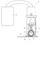
- FIG. 1 is a schematic view showing a spinning apparatus according to one embodiment.
- FIG. 2A is a schematic view showing the configuration of a sheet forming machine according to an embodiment.
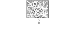
- FIG. 2B is a view showing an enlarged image of the range A1 of FIG. 2A.
- FIG. 3 is a schematic view showing the configuration of a stripping machine according to one embodiment.
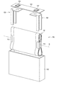
- FIG. 4 is a perspective view schematically showing an example of a battery in which a negative electrode is integrally formed with a separator by the spinning device according to one embodiment.
- FIG. 5 is a schematic view showing the structure of the connection portion of the electrode group with one of the leads in the battery of FIG. FIG.
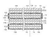
- FIG. 6 is a cross sectional view schematically showing a laminated state of a positive electrode and a negative electrode in the electrode group of the battery of FIG.
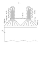
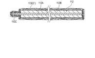
- FIG. 7 is a cross-sectional view schematically showing the state of the negative electrode immediately after the processing by the sheet forming machine is completed when the separator is integrally formed with the negative electrode by the spinning apparatus according to one embodiment.
- FIG. 8 is a cross-sectional view schematically showing the state of the negative electrode immediately after the processing by the stripping machine is completed when the separator is integrally formed with the negative electrode by the spinning apparatus according to an embodiment.
- FIG. 9 is a graph showing experimental data on the influence of each wire diameter and bristle length of the brush hair on the removal of organic fibers by the rotating brush according to one embodiment.
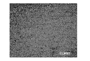
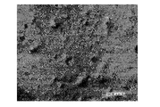
- FIG. 10A is a view showing an optical microscope image of a site at which the organic fiber is peeled off on the surface of the negative electrode current collector foil when the organic fiber is peeled off under the condition X9 of FIG.
- FIG. 10B is a view showing an optical microscope image of a site at which the organic fiber is stripped off on the surface of the negative electrode current collector foil when the organic fiber is stripped off under condition X4 in FIG. 9.
- FIG. 10C is a view showing an optical microscope image of a site at which the organic fiber is peeled off on the surface of the negative electrode current collector foil when the organic fiber is peeled off under the condition X7 of FIG. 9.
- FIG. 1 shows a spinning device 1 according to an embodiment.
- the spinning device 1 includes a sheet forming machine 2 and a stripping machine 5. Further, in the spinning device 1, a transport line 6 is formed.
- the base material 50 (see FIGS. 2A and 3) is transported by the transport line 6 in the order of the sheet forming machine 2 and the stripping machine 5.
- FIG. 2A shows the configuration of the sheet forming machine 2.
- FIG. 2B is shown with the image which expanded range A1 of FIG. 2A.
- the sheet forming machine 2 comprises a spinning head 11 and a voltage generator 12.
- the sheet 51 of the organic fiber 52 is formed on the surface of the substrate 50 by electrospinning (electro spinning) in the sheet forming machine 2 (see FIG. 2B).
- electrospinning electro spinning
- the spinning head 11 comprises a nozzle 13 capable of ejecting the filled organic material. Only one nozzle 13 may be provided, or a plurality of nozzles may be provided.
- polyolefins include polypropylene (PP) and polyethylene (PE).
- the organic material is dissolved in the solvent at a concentration of about 5% by mass to 60% by mass.
- a solvent for dissolving the organic material any solvent such as dimethyl acetoamide (DMAc), dimethyl sulfoxide (DMSO), N, N 'dimethylformamide (DMF), N-methyl pyrrolidone (NMP), water and alcohols Is used.
- DMAc dimethyl acetoamide
- DMSO dimethyl sulfoxide
- DMF N, N 'dimethylformamide
- NMP N-methyl pyrrolidone
- water and alcohols water and alcohols
- the sheet-like organic material may be melted by a laser or the like during electrospinning.
- a high boiling point organic solvent and a low melting point solvent may be mixed.
- the voltage generator 12 applies a voltage (high voltage) between the spinning head 11 and the substrate 50.
- a voltage high voltage
- a solution of an organic material is ejected from the nozzles 13 of the spinning head 11 to the surface of the substrate 50.
- the sheet (layer) 51 of the organic fiber 52 is formed on the surface of the base material 50.
- the sheet 51 is an insulating layer having electrical insulation.
- the voltage between the spinning head 11 and the substrate 50 is the type of solvent and solute, the boiling point and vapor pressure curve of the solvent, the solution concentration, the temperature, the shape of the nozzle 13, and the shape between the substrate 50 and the nozzle 13. It is appropriately determined according to the distance and the like, and is appropriately determined, for example, between 1 kV and 100 kV. Further, the supply rate of the solution of the organic material is appropriately determined in accordance with the solution concentration, solution viscosity, temperature, pressure, applied voltage, shape of the nozzle 13 and the like.
- the formation of the sheet 51 of the organic fibers 52 may be performed by a technique other than the electrospinning method.
- the sheet 51 of the organic fiber 52 may be formed on the surface of the substrate 50 by any of an inkjet method, a jet dispenser method and a spray application method instead of the electrospinning method.
- the substrate 50 on which the sheet 51 is formed is conveyed to the stripping machine 5. Then, processing by the stripping machine 5 is performed.
- FIG. 3 shows the configuration of the stripper 5.
- the stripping machine 5 includes a rotating brush 21, a suction head 22, and a dust collector 23.
- the rotating brush 21 is mounted on the suction head 22, and in the present embodiment, is disposed inside the suction head 22.
- the rotating brush 21 is rotatable around the axis of rotation R with respect to the suction head 22.
- the suction head 22 has a suction port 25, and the inside of the suction head 22 is opened to the outside through the suction port 25.
- the cleaner 26 is disposed inside the suction head 22, and the rotation axis R is located between the suction port 25 and the cleaner 26. Further, in the state where the dust collector 23 is driven, a suction force acts on the inside of the suction head 22 from the suction port 25 of the suction head 22, and a suction force acts on the dust collector 23 from the inside of the suction head 22.
- the rotating brush 21 is brought into contact with the sheet 51 of the organic fiber 52 on the surface of the base material 50. At this time, the rotary brush 21 contacts the sheet 51 at the suction port 25 of the suction head 22. Then, in a state where the rotary brush 21 contacts the sheet 51, the rotary brush 21 is rotationally driven.
- the organic fibers 52 are peeled off from the sheet 51 by the rotational drive of the rotary brush 21. In the present embodiment, the organic fibers 52 are peeled off at a part of the sheet 51 by the rotating brush 21. Therefore, even after the processing by the stripping machine 5 is completed, the sheet 51 of the organic fiber 52 is formed on the surface of the base material 50 at a portion where stripping by the rotating brush 21 is not performed.
- the dust collector 23 is driven.
- the organic fibers 52 stripped off by the rotating brush 21 are sucked into the inside of the suction head 22 from the suction port 25 of the suction head 22.
- the organic fibers 52 sucked into the suction head 22 are sucked and collected by a tank (not shown) or the like provided in the dust collector 23.
- the cleaner 26 removes the organic fibers 52 and the like attached to the rotating brush 21.
- the organic fibers 52 and the like removed from the rotating brush 21 by the cleaner 26 are also sucked and collected by the tank or the like of the dust collector 23.
- the rotating brush 21 includes a plurality of (multiple) brush bristles 27.
- Each of the brush bristles 27 is formed of chemical fibers or animal fibers. Chemical fibers forming the brush bristles 27 include nylon, polypropylene, vinyl chloride, polyester, acrylic resin, aramid and Teflon (registered trademark).
- the animal fibers forming the brush bristles 27 include horse hair, pig hair, wool and deer hair.
- Each of the brush bristles 27 has a wire diameter of 0.1 mm or more and 0.5 mm or less, and a hair length of 30 mm or less.
- each wire diameter and diameter of brush bristles 27 are set to an appropriate size within the above-mentioned range.
- the spinning device 1 of the present embodiment is used, for example, when forming a positive electrode or a negative electrode integrally with a separator in a battery such as a non-aqueous electrolyte secondary battery or an alkaline secondary battery.
- FIG. 4 shows a battery 100.
- a separator integrated electrode in which the negative electrode 112 (see FIG. 6) is integrally formed with the separator 113 (see FIG. 6) by the spinning device 1 is used.
- the battery 100 is, for example, a sealed non-aqueous electrolyte secondary battery.
- the battery 100 includes an electrode group 101, an outer can 102 in which the electrode group 101 is accommodated, a positive electrode lead 103 and a negative electrode lead 104 located in the outer can 102, and a lid 105 attached to the opening of the outer can 102. And the positive electrode terminal 106 and the negative electrode terminal 107 provided on the lid 105.
- the outer can 102 is formed of a metal such as aluminum, aluminum alloy, iron or stainless steel. Further, in the inside of the outer can 102, the electrode group 101 is impregnated with an electrolytic solution (not shown). Instead of the outer can 102, a packaging material made of laminated film may be provided, and the electrode group 101 may be accommodated in the packaging material. Further, the positive electrode lead 103 is electrically insulated from the package can 102 and the lid 105, and is electrically connected to the positive electrode terminal 106. The negative electrode lead 104 is electrically insulated from the package can 102 and the lid 105, and is also electrically connected to the negative electrode terminal 107.
- FIG. 5 shows the configuration of the connection portion of the electrode group 101 with one of the leads 103 and 104
- FIG. 6 shows the stacked state of the positive electrode 111 and the negative electrode 112 in the electrode group 101.
- the electrode group 101 includes the above-described positive electrode 111 and negative electrode 112, and a separator 113, and the separator 113 is integrally formed with the negative electrode 112.
- the separator 113 is in close contact with the surface of the negative electrode 112 in a fixed state, and the separator 113 electrically insulates between the positive electrode 111 and the negative electrode 112.
- the separator 113 is formed on the surface of the negative electrode 112 by the above-described spinning device 1.
- the separator 113 is formed by the electrospinning method or the like, and is formed of the above-described organic material filled in the inside of the spinning head 11. Therefore, when the separator 113 is integrally formed with the negative electrode 112 by the spinning apparatus 1, the negative electrode 112 is the base 50, and the separator 113 is the sheet 51 of the organic fibers 52 formed on the surface of the negative electrode 112.
- the separator 113 is formed on the negative electrode 112 by the spinning device 1.
- the positive electrode 111 includes a positive electrode current collector foil 111A as a positive electrode current collector, and a positive electrode active material containing layer 111B supported on the surface of the positive electrode current collector foil 111A.
- the positive electrode current collector foil 111A is, for example, an aluminum foil or an aluminum alloy foil, and has a thickness of about 10 ⁇ m to 20 ⁇ m.
- a slurry containing a positive electrode active material, a binder, and a conductive agent is applied to the positive electrode current collector foil 111A.
- the positive electrode active material include oxides, sulfides, and polymers that can occlude and release lithium. Further, from the viewpoint of obtaining a high positive electrode potential, as the positive electrode active material, lithium manganese composite oxide, lithium nickel composite oxide, lithium cobalt composite oxide, lithium iron phosphate and the like are preferably used.
- the negative electrode 112 includes a negative electrode current collector foil 112A as a negative electrode current collector, and a negative electrode active material containing layer 112B supported on the surface of the negative electrode current collector foil 112A.
- the negative electrode current collector foil 112A is, for example, an aluminum foil or an aluminum alloy foil, and has a thickness of about 10 ⁇ m to 20 ⁇ m.
- a slurry containing a negative electrode active material, a binder, and a conductive agent is applied to the negative electrode current collector foil 112A.
- the negative electrode active material metal oxides, metal sulfides, metal nitrides, alloys and the like which can occlude and release lithium can be mentioned, and substances having a lithium ion absorption and release potential of 0.4 V or more with respect to the metal lithium potential Is preferred.
- the negative electrode active material having the lithium ion storage and release potential as described above, an alloy reaction between aluminum or an aluminum alloy and lithium can be suppressed. Therefore, aluminum can be used as a component related to negative electrode current collector foil 112A and negative electrode 112 And aluminum alloys can be used.
- lithium titanium composite oxide such as titanium oxide and lithium titanate, tungsten oxide, amorphous tin oxide, tin silicon oxide, silicon oxide and the like can be mentioned, and lithium titanium It is particularly preferable to use a composite oxide as the negative electrode active material.
- the aluminum alloy used for the positive electrode current collector and the negative electrode current collector preferably contains one or more elements selected from Mg, Ti, Zn, Mn, Fe, Cu and Si.
- the purity of aluminum and aluminum alloy can be 98% by weight or more, preferably 99.99% by weight or more.
- pure aluminum having a purity of 100% can be used as a material of the positive electrode current collector and / or the negative electrode current collector.
- the content of transition metals such as nickel and chromium in aluminum and aluminum alloys is preferably 100 ppm by weight or less (including 0 ppm by weight).
- the positive electrode 111, the negative electrode 112, and the separator 113 have a flat shape centering on the winding axis B in a state where the separator 113 is disposed between the positive electrode 111 and the negative electrode 112. It is wounded by For this reason, in the electrode group 101, the positive electrode 111 and the negative electrode 112 are alternately stacked via the separator 113 therebetween.
- the positive electrode current collector foil 111A each of the pair of side edges is formed by the corresponding long side, and one of the side edges and the vicinity thereof form the positive electrode current collector tab 111C.
- the positive electrode current collection tab 111C is formed over a predetermined distance from one of the side edges in the direction along the winding axis B, and the positive electrode active material containing layer 111B is not supported by the positive electrode current collection tab 111C.
- each of the pair of side edges is formed by the corresponding long side, and the negative electrode current collector tab 112C is formed by one of the side edges and the vicinity thereof.
- the negative electrode current collection tab 112C is formed over a predetermined distance from one of the side edges in the direction along the winding axis B, and the negative electrode active material containing layer 112B is not supported on the negative electrode current collection tab 112C.
- the positive electrode 111 and the negative electrode 112 are disposed in a state of being shifted relative to each other in the direction along the winding axis B. For this reason, the positive electrode current collection tab 111C which is not supported by the positive electrode active material-containing layer 111B protrudes to one side in the direction along the winding axis B with respect to the negative electrode 112 and the separator 113. Then, the negative electrode current collection tab 112C, which does not support the negative electrode active material-containing layer 112B, is opposite to the side where the positive electrode current collection tab 111C protrudes in the direction along the winding axis B with respect to the positive electrode 111 and the separator 113. Stand out. In one example of FIGS. 4 to 6, the direction along the winding axis B is parallel or substantially parallel to the long side direction of the lid 105.
- the surfaces of the positive electrode current collector foil 111A are joined together by ultrasonic welding or the like. Further, the positive electrode current collection tab 111C is bundled by the positive electrode backup lead 115 and is joined to the positive electrode backup lead 115 by ultrasonic welding or the like. The positive electrode backup lead 115 is joined to the positive electrode lead 103 by ultrasonic welding or the like. Therefore, the positive electrode current collector foil 111A is electrically connected to the positive electrode terminal 106 through the positive electrode backup lead 115 and the positive electrode lead 103.
- the surfaces of the negative electrode current collection foil 112A are joined by ultrasonic welding or the like.
- the negative electrode current collection tab 112C is bundled by the negative electrode backup lead 116, and is joined to the negative electrode backup lead 116 by ultrasonic welding or the like.
- the negative electrode backup lead 116 is joined to the negative electrode lead 104 by ultrasonic welding or the like. Therefore, the negative electrode current collector foil 112A is electrically connected to the negative electrode terminal 107 via the negative electrode backup lead 116 and the negative electrode lead 104.
- the separator 113 is formed, for example, on the surface of the negative electrode 112, using the spinning device 1.
- the slurry containing the negative electrode active material is applied to the negative electrode current collector foil 112A before the treatment by the spinning device 1 is performed.
- the slurry containing a negative electrode active material is not apply
- the negative electrode active material containing layer 112B is formed at a portion other than the portion where the negative electrode current collector tab 112C is formed.
- FIG. 7 shows the state of the negative electrode 112 immediately after the processing by the sheet forming machine 2 is completed.
- the sheet 51 of the organic fiber 52 is formed over the entire surface of the negative electrode 112. For this reason, immediately after the treatment with the sheet forming machine 2, both of the portion on the negative electrode current collector foil 112A on which the negative electrode active material containing layer 112B is supported and the region on which the negative electrode active material containing layer 112B is not supported are Covered.
- the portion forming the negative electrode current collection tab 112 ⁇ / b> C is also covered by the sheet 51. Further, immediately after the processing in the sheet forming machine 2, both side edges of the negative electrode current collector foil 112 ⁇ / b> A, that is, both long sides are also covered by the sheet 51.
- FIG. 8 shows the state of the negative electrode 112 immediately after the treatment by the stripping machine 5 is completed.
- the organic fiber 52 is stripped off at a part of a portion where the negative electrode current collection tab 112 ⁇ / b> C is formed.
- the negative electrode current collection tab 112C the organic fiber 52 is stripped off over the predetermined dimension L1 from the side edge by the side of the negative electrode current collection tab 112C of the negative electrode current collection foil 112A.
- the predetermined dimension L1 is smaller than the distance L2 from the side edge on the negative electrode current collector tab 112C side of the negative electrode current collector foil 112A to the end on the negative electrode current collector tab 112C side of the negative electrode active material containing layer 112B. For this reason, in the negative electrode current collection tab 112C in which the negative electrode active material containing layer 112B is not supported, the organic fiber 52 is not peeled off over the whole. Therefore, even after the treatment by the stripping machine 5 is completed, a part of the negative electrode current collection tab 112C is covered by the sheet 51 of the organic fiber 52.
- the negative electrode current collection tab 112C By partially covering the negative electrode current collection tab 112C with the sheet 51, the negative electrode current collection tab 112C with respect to the non-supported portion of the positive electrode active material containing layer 111B at the edge of the positive electrode 111 opposite to the positive electrode current collection tab 111C. Insulation is secured. In addition, the insulation of the positive electrode current collection tab 111C with respect to the non-supported portion of the negative electrode active material containing layer 112B is also secured at the edge of the negative electrode 112 opposite to the negative electrode current collection tab 112C.
- the sheet forming machine 2 forms the sheet 51 over the entire surface of the negative electrode 112 which is the base material 50. Therefore, in the sheet forming machine 2, it is not necessary to perform control or the like so that the sheet 51 of the organic fiber 52 is not formed in the non-supported portion of the negative electrode active material containing layer 112B of the negative electrode current collector foil 112A. For this reason, in the sheet forming machine 2, the control of the spinning head 11, the voltage generator 12, etc. does not become complicated. Further, since the sheet 51 is formed over the entire surface of the negative electrode 112, uniformity of the film thickness of the sheet 51 of the organic fiber 52 is secured. Therefore, the sheet 51 of the organic fiber 52 is appropriately formed integrally with the negative electrode 112 which is the base material 50.
- the stripping machine 5 peels off the organic fibers 52 from a part of the portion forming the negative electrode current collection tab 112 ⁇ / b> C. That is, the organic fiber 52 is appropriately removed from the portion where the negative electrode current collector foil 112A is joined. By appropriately removing the organic fibers 52 from a part of the portion forming the negative electrode current collection tab 112C, the surfaces of the negative electrode current collection foil 112A are appropriately joined to each other in the negative electrode current collection tab 112C. In addition, by appropriately removing the organic fiber 52 from a part of a portion forming the negative electrode current collection tab 112C, the negative electrode current collection tab 112C is appropriately joined to the negative electrode lead 104 via the negative electrode backup lead 116. .
- the organic fibers 52 peeled off by the rotating brush 21 are sucked from the suction port 25 of the suction head 22 and collected by the dust collector 23. For this reason, the stripped organic fibers 52 are properly recovered.
- FIG. 9 shows experimental data on the influence of the respective wire diameters and bristle length of the brush bristles 27 on the removal of the organic fibers 52 by the rotating brush 21.
- each of the brush bristles 27 is condition X1 (wire diameter 0.1 mm, hair height 3 mm), condition X2 (wire diameter 0.1 mm, hair height 5 mm), condition X3 (wire diameter 0.1 mm) , Height 8 mm), condition X 4 (wire diameter 0.2 mm, hair length 4 mm), condition X 5 (wire diameter 0.2 mm, hair length 8 mm), condition X 6 (wire diameter 0.2 mm, height 12 mm), condition X 7 (Wire diameter 0.2 mm, hair length 17 mm), condition X8 (wire diameter 0.3 mm, hair length 8 mm), condition X9 (wire diameter 0.3 mm, hair length 12 mm), condition X10 (wire diameter 0.3 mm, hair In the case of height 15 mm, condition X11 (wire diameter 0.3 mm, condition 0.3
- the same base 50 as the above-described negative electrode 112 was used, and the organic fiber 52 was formed by the electrospinning method. Then, under any of the conditions X1 to X13, polyimide was used as the organic material for forming the organic fiber 52, and N-methylpyrrolidone (NMP) was used as the solvent for dissolving the organic material. Further, under any of the conditions X1 to X13, verification was performed with the voltage between the spinning head 11 and the base material 50 set to 30 kV.
- an aluminum alloy foil having a purity of aluminum of 99% by weight or more and a thickness of 15 ⁇ m was used as the negative electrode current collector foil 112A forming the base 50.
- lithium titanate having a spinel structure was used as the negative electrode active material.
- the area ratio of the organic fiber 52 in the part which peeled off the organic fiber 52 was acquired, and the effect of each wire diameter and hair length of the brush hair 27 on the removal of the organic fiber 52 based on the acquired area ratio Verified.
- the area ratio is the ratio of the area occupied by the non-removed organic fiber 52 to the area of the entire range of 6 mm from the side edge on the negative electrode current collector tab 112C side of the negative electrode current collector foil 112A.
- the aforementioned predetermined dimension L1 from which the organic fiber 52 is peeled off is the same as or substantially the same as 6 mm.
- a distance L2 from the side edge on the negative electrode current collection tab 112C side of the negative electrode current collector foil 112A to the end on the negative electrode current collection tab 112C side of the negative electrode active material containing layer 112B is larger than 6 mm.
- image data in a range of 6 mm is acquired from the side edge of the negative electrode current collector tab 112C of the negative electrode current collector foil 112A, and the acquired image data is binarized Is calculated.
- the area ratio of the organic fibers 52 became 20% or less after peeling off the organic fibers 52 under any of the conditions X1 to X13.
- the area ratio of the organic fiber 52 in the above-mentioned range is 90% or more. Therefore, regardless of the conditions X1 to X13, the organic fibers 52 are removed from the surface of the negative electrode current collector foil 112A (base material 50) as compared to before the removal. Therefore, by setting the wire diameter to 0.1 mm or more and 0.5 mm or less and setting the hair length to 30 mm or less for each of the brush bristles 27, an appropriate amount of organic fibers 52 can be obtained from the surface of the substrate 50. It is removed.
- the bonding strength of the surfaces of the negative electrode current collector foil 112A in the negative electrode current collector tab 112C is secured by setting the wire diameter and the hair length in the above-mentioned range for each of the brush bristles 27, and the negative electrode current collector tab 112C The bonding strength to the negative electrode backup lead 116 and the negative electrode lead 104 is secured.
- the aforementioned area ratio was 5% or less under the conditions X1, X4, X5, and X8 to X13. That is, among the conditions X1 to X13, the removal amount of the organic fiber 52 from the surface of the substrate 50 was large under the conditions X1, X4, X5, and X8 to X13. Therefore, even when the wire diameter is 0.1 mm or more and 0.5 mm or less and the hair length is 30 mm or less in each of the brush bristles 27, particularly when the wire diameter is larger than 0.2 mm, or When the ratio of hair length to diameter is smaller than 50, the amount of removal of the organic fibers 52 from the surface of the substrate 50 is increased.
- the bonding strength of the surfaces of the negative electrode current collector foil 112A in the negative electrode current collecting tab 112C is further improved, and the bonding strength of the negative electrode current collecting tab 112C to the negative electrode backup lead 116 and the negative electrode lead 104 is further improved.
- Whether or not unevenness is formed in the portion where the organic fiber 52 is peeled off on the surface of the substrate 50 changes depending on the material forming the substrate 50, the thickness of the substrate 50, and the like. For example, it changes corresponding to the purity of aluminum in the negative electrode current collector foil 112A, the thickness of the negative electrode current collector foil 112A, and the like. When the purity of aluminum is 98% by weight or more and the thickness is in the range of 10 ⁇ m to 20 ⁇ m, the same tendency as shown in the experimental data of FIG. 9 is obtained.
- FIG. 9 the above-mentioned conditions X1, X4, X5, and X8 to X13 having an area ratio of 5% or less are black circles, and the area ratio is not less than 5% and not more than 20%. , X7 in black triangles.
- or FIG. 10C the optical microscope image of the site
- FIG. 10A shows the case where it peeled off under condition X9
- FIG. 10B shows the case where it peeled off under condition X7, when FIG. 10B peeled off under condition X4.
- the removal amount of the organic fiber 52 by the rotating brush 21 is larger at the conditions X4 and X9 than at the condition X7. Further, under the condition X9, the surface of the base material 50 becomes smooth at the portion where the organic fiber 52 is peeled off, as compared to the condition X4.
- the spinning head includes a sheet of organic fibers formed on the surface of a substrate, and a rotating brush that peels off the organic fibers in a part of the sheet. For this reason, it is possible to provide a spinning device that appropriately forms a sheet of organic fibers integrally with the electrode by spinning, and appropriately removes the organic fiber from the portion of the electrode to which the current collector is joined after spinning.
Landscapes
- Engineering & Computer Science (AREA)
- Textile Engineering (AREA)
- Mechanical Engineering (AREA)
- Chemical & Material Sciences (AREA)
- Chemical Kinetics & Catalysis (AREA)
- Electrochemistry (AREA)
- General Chemical & Material Sciences (AREA)
- Spinning Methods And Devices For Manufacturing Artificial Fibers (AREA)
- Nonwoven Fabrics (AREA)
- Secondary Cells (AREA)
- Battery Electrode And Active Subsutance (AREA)
Abstract
紡糸装置(1)は、紡糸ヘッド(11)と、回転ブラシ(21)と、を備える。紡糸ヘッド(11)の内部には有機材料が充填され、紡糸ヘッド(11)は、基材(50)の表面に有機材料を噴出し、基材(50)の表面に有機繊維(52)のシート(51)を形成する。回転ブラシ(21)は、複数のブラシ毛(27)を備え、基材(50)の表面においてシート(51)にブラシ毛(27)が接触する状態で回転駆動される。回転ブラシ(21)は、回転駆動によって、シート(51)の一部において有機繊維(52)を剥ぎ取る。
Description
本発明の実施形態は、紡糸装置に関する。
二次電池等の電池には、正極と負極との間を絶縁するセパレータが正極又は負極と一体に形成されるものがある。この電池の製造では、セパレータと一体に形成される電極(正極又は負極)の表面に、例えば、電界紡糸法(エレクトロスピニング法)によって、有機繊維のシートを形成する。そして、有機繊維のシートが、正極と負極との間のセパレータとなる。
正極及び負極のそれぞれは、例えば金属箔からなる集電体と、集電体の表面に担持される活物質と、を備える。また、正極及び負極のそれぞれでは、集電体の側縁の一方及びその近傍によって集電タブが形成され、集電タブには活物質が担持されない。そして、集電タブでは、集電体の表面同士が接合されるとともに、集電体がバックアップリード等に接合される。このため、前述のように電界紡糸法によって電極の一方と一体にセパレータを形成する場合、電極の全面に電界紡糸法によって有機繊維のシートを形成した後、集電体において活物質が無担持の部分、すなわち、集電タブを形成する部分から、有機繊維を除去する必要がある。
なお、電界紡糸法では、制御等によって、集電体の活物質が無担持の部分に、有機繊維のシートを形成しないことは可能である。ただし、電界紡糸法においてこのような制御を行った場合、有機繊維のシートの膜厚の均一性に影響を及ぼす可能性がある。
本発明が解決しようとする課題は、紡糸によって電極と一体に有機繊維のシートを適切に形成し、紡糸後に電極において集電体を接合する部分から有機繊維を適切に除去する紡糸装置を提供することにある。
実施形態によれば、紡糸装置は、紡糸ヘッドと、回転ブラシと、を備える。紡糸ヘッドの内部には有機材料が充填され、紡糸ヘッドは、基材の表面に有機材料を噴出し、基材の表面に有機繊維のシートを形成する。回転ブラシは、複数のブラシ毛を備え、基材の表面においてシートにブラシ毛が接触する状態で回転駆動される。回転ブラシは、回転駆動によって、シートの一部において有機繊維を剥ぎ取る。
以下、実施形態について、図1乃至図10Cを参照して説明する。
図1は、一実施形態に係る紡糸装置1を示す。図1に示すように、紡糸装置1は、シート形成機2及び剥ぎ取り機5を備える。また、紡糸装置1には、搬送ライン6が形成される。紡糸装置1では、基材50(図2A及び図3参照)が、搬送ライン6によって、シート形成機2及び剥ぎ取り機5の順に搬送される。
図2Aは、シート形成機2の構成を示す。また、図2Bは、図2Aの範囲A1を拡大した画像で示す。図2Aに示すように、シート形成機2は、紡糸ヘッド11及び電圧発生器12を備える。本実施形態では、シート形成機2において、電界紡糸法(エレクトロスピニング法)によって、基材50の表面に有機繊維52のシート51が形成される(図2B参照)。紡糸ヘッド11の内部には、有機材料が溶媒に溶解した溶液が充填される。紡糸ヘッド11は、充填された有機材料を噴出可能なノズル13を備える。ノズル13は、1つのみ設けられてもよく、複数設けられてもよい。紡糸ヘッド11に充填される有機材料としては、例えば、ポリオレフィン、ポリエーテル、ポリイミド、ポリケトン、ポリスルホン、セルロース、ポリビニルアルコール(PVA)、ポリアミド、ポリアミドイミド及びポリフッ化ビニリデン(PVdf)のいずれか1以上が選択される。ポリオレフィンとしては、例えば、ポリプロピレン(PP)及びポリエチレン(PE)等が挙げられる。
また、紡糸ヘッド11の内部では、有機材料は、5質量%~60質量%程度の濃度で、溶媒に溶解される。有機材料を溶解する溶媒としては、ジメチルアセドアミド(DMAc)、ジメチルスルホキシド(DMSO)、N,N‘ジメチルホルムアミド(DMF)、N-メチルピロリドン(NMP),水及びアルコール類等の任意の溶媒が用いられる。また、溶解性の低い有機材料に対しては、電界紡糸法を行っている最中に、レーザー等によってシート状の有機材料を溶融してもよい。さらに、有機材料の溶液では、高沸点の有機溶剤と低融点の溶剤とが混合されてもよい。
電圧発生器12は、紡糸ヘッド11と基材50との間に電圧(高電圧)を印加する。紡糸ヘッド11と基材50との間に電圧が印加されることにより、紡糸ヘッド11のノズル13から基材50の表面に、有機材料の溶液が噴出される。これにより、基材50の表面に、有機繊維52のシート(層)51が形成される。シート51は、電気的絶縁性を有する絶縁層である。
紡糸ヘッド11と基材50との間の電圧は、溶媒及び溶質の種類、溶媒の沸点及び蒸気圧曲線、溶液濃度、温度、ノズル13の形状、及び、基材50とノズル13との間の距離等に対応して、適宜決定され、例えば1kV~100kVの間で適宜決定される。また、有機材料の溶液の供給速度は、溶液濃度、溶液粘度、温度、圧力、印加電圧、及び、ノズル13の形状等に対応して、適宜決定される。
また、有機繊維52のシート51の形成、すなわち、基材50の表面への有機繊維52の紡糸は、電界紡糸法以外の手法によって行われてもよい。例えば、電界紡糸法の代わりに、インクジェット法、ジェットディスペンサー法及びスプレー塗布法のいずれかによって、基材50の表面に有機繊維52のシート51が形成されてもよい。
電界紡糸法等の紡糸によって基材50に有機繊維52のシート51が形成された後、シート51が形成された基材50は、剥ぎ取り機5に搬送される。そして、剥ぎ取り機5による処理が行われる。
図3は、剥ぎ取り機5の構成を示す。剥ぎ取り機5は、回転ブラシ21と、吸引ヘッド22と、集塵機23と、を備える。回転ブラシ21は、吸引ヘッド22に搭載され、本実施形態では、吸引ヘッド22の内部に配置される。回転ブラシ21は、吸引ヘッド22に対して、回転軸Rの軸回りに回転可能である。また、吸引ヘッド22は、吸引口25を有し、吸引ヘッド22の内部は吸引口25で外部に開口する。そして、吸引ヘッド22の内部には、クリーナー26が配置され、回転軸Rは、吸引口25とクリーナー26との間に位置する。また、集塵機23が駆動された状態では、吸引ヘッド22の吸引口25から吸引ヘッド22の内部へ吸引力が作用するとともに、吸引ヘッド22の内部から集塵機23へ吸引力が作用する。
本実施形態では、基材50の表面において有機繊維52のシート51に、回転ブラシ21を接触させる。この際、吸引ヘッド22の吸引口25において、回転ブラシ21がシート51に接触する。そして、回転ブラシ21がシート51に接触する状態で、回転ブラシ21が回転駆動される。回転ブラシ21の回転駆動によって、シート51において有機繊維52が剥ぎ取られる。本実施形態では、回転ブラシ21によって、シート51の一部で、有機繊維52が剥ぎ取られる。したがって、剥ぎ取り機5での処理が完了後においても、基材50の表面には、回転ブラシ21による剥ぎ取りが行われていない部位に、有機繊維52のシート51が形成される。
また、回転ブラシ21が回転駆動されている状態では、集塵機23が駆動される。これにより、回転ブラシ21によって剥ぎ取られた有機繊維52が、吸引ヘッド22の吸引口25から吸引ヘッド22の内部へ吸引される。そして、吸引ヘッド22の内部に吸引された有機繊維52は、集塵機23に設けられるタンク(図示しない)等に吸引回収される。また、クリーナー26は、回転ブラシ21に付着した有機繊維52等を除去する。そして、クリーナー26によって回転ブラシ21から除去された有機繊維52等も、集塵機23のタンク等に吸引回収される。なお、吸引口25から剥ぎ取られた有機繊維52を吸引している状態では、吸引ヘッド22の内部での吸引通路の断面積に比べて、吸引ヘッド22と基材50との間での吸引通路の断面積が、小さい。このため、吸引口25から剥ぎ取られた有機繊維52を吸引している状態では、吸引ヘッド22の内部での空気の流速に比べて、吸引ヘッド22と基材50との間での空気の流速が、大きい。
回転ブラシ21は、複数(多数)のブラシ毛27を備える。ブラシ毛27のそれぞれは、化学繊維又は動物繊維から形成される。ブラシ毛27を形成する化学繊維としては、ナイロン、ポリプロピレン、塩化ビニル、ポリエステル、アクリル樹脂、アラミド及びテフロン(登録商標)が挙げられる。ブラシ毛27を形成する動物繊維としては、馬毛、豚毛、羊毛及び鹿毛が挙げられる。ブラシ毛27のそれぞれは、線径が0.1mm以上かつ0.5mm以下であるとともに、毛丈が30mm以下である。
ただし、ブラシ毛27のそれぞれの線径及び毛丈が前述の範囲内であっても、線径に対する毛丈の比率が大きい場合、基材50における回転ブラシ21による有機繊維52の除去量が低下する。また、ブラシ毛27のそれぞれの線径及び毛丈が前述の範囲内であっても、線径に対する毛丈の比率が小さい場合、有機繊維52の剥ぎ取り後において、基材50の表面に凸凹が形成され易い。さらに、ブラシ毛27のそれぞれの線径及び毛丈が前述の範囲内であっても、毛丈が小さい場合、回転ブラシ21の寿命が短くなる。したがって、前述の事項に対応させて、ブラシ毛27のそれぞれの線径及び径丈は、前述の範囲内において適宜の寸法に設定される。
本実施形態の紡糸装置1は、例えば、非水電解質二次電池やアルカリ二次電池等の電池において、正極又は負極をセパレータと一体に形成する際に用いられる。図4は、電池100を示し、電池100では、紡糸装置1によって負極112(図6参照)がセパレータ113(図6参照)と一体に形成されたセパレータ一体型電極が用いられる。ここで、電池100は、例えば、密閉型の非水電解質二次電池である。電池100は、電極群101と、内部に電極群101が収容される外装缶102と、外装缶102内に位置する正極リード103及び負極リード104と、外装缶102の開口部に取り付けられる蓋105と、蓋105に設けられる正極端子106及び負極端子107と、を備える。
外装缶102は、アルミニウム、アルミニウム合金、鉄又はステンレス等の金属から形成される。また、外装缶102の内部では、電極群101に、電解液(図示しない)が含浸される。なお、外装缶102の代わりに、ラミネートフィルム製包材が設けられ、電極群101は、包材に収容されてもよい。また、正極リード103は、外装缶102及び蓋105に対して電気的に絶縁されるとともに、正極端子106に電気的に接続される。そして、負極リード104は、外装缶102及び蓋105に対して電気的に絶縁されるとともに、負極端子107に電気的に接続される。
図5は、リード103,104の一方との電極群101の接続部分の構成を示し、図6は、電極群101での正極111及び負極112の積層状態を示す。図4乃至図6の一例では、電極群101は、前述の正極111及び負極112と、セパレータ113と、を備え、セパレータ113は、負極112と一体に形成される。セパレータ113は、負極112の表面に固定された状態で密着し、セパレータ113によって、正極111と負極112との間が電気的に絶縁される。セパレータ113は、前述の紡糸装置1によって、負極112の表面に形成される。このため、セパレータ113は、電界紡糸法等によって形成され、紡糸ヘッド11の内部に充填される前述の有機材料から形成される。したがって、紡糸装置1によってセパレータ113を負極112と一体に形成する場合、負極112が基材50となり、セパレータ113が負極112の表面に形成される有機繊維52のシート51となる。なお、以下の説明では、セパレータ113が負極112に形成される場合について説明するが、紡糸装置1によって正極111の表面にセパレータ113が形成される場合も、同様である。
正極111は、正極集電体としての正極集電箔111Aと、正極集電箔111Aの表面に担持される正極活物質含有層111Bと、を備える。正極集電箔111Aは、アルミニウム箔又はアルミニウム合金箔等であり、厚さが10μm~20μm程度である。正極集電箔111Aには、正極活物質、結着剤及び導電剤を含むスラリーが塗布される。正極活物質としては、リチウムを吸蔵放出できる酸化物、硫化物及びポリマー等が挙げられる。また、高い正極電位を得られる観点から、正極活物質は、リチウムマンガン複合酸化物、リチウムニッケル複合酸化物、リチウムコバルト複合酸化物及びリチウム燐酸鉄等が、用いられることが好ましい。
負極112は、負極集電体としての負極集電箔112Aと、負極集電箔112Aの表面に担持される負極活物質含有層112Bと、を備える。負極集電箔112Aは、アルミニウム箔又はアルミニウム合金箔等であり、厚さが10μm~20μm程度である。負極集電箔112Aには、負極活物質、結着剤及び導電剤を含むスラリーが塗布される。負極活物質としては、リチウムを吸蔵放出できる金属酸化物、金属硫化物、金属窒化物及び合金等が挙げられ、リチウムイオンの吸蔵放出電位が金属リチウム電位に対して0.4V以上となる物質であることが好ましい。前述のようなリチウムイオン吸蔵放出電位を有する負極活物質を用いることにより、アルミニウム又はアルミニウム合金とリチウムとの合金反応が抑えられるため、負極集電箔112A及び負極112に関連する構成部材に、アルミニウム及びアルミニウム合金を使用可能になる。したがって、負極活物質としては、例えば、チタン酸化物及びチタン酸リチウム等のリチウムチタン複合酸化物、タングステン酸化物、アモルファススズ酸化物、スズ珪素酸化物、及び、酸化珪素等が挙げられ、リチウムチタン複合酸化物を負極活物質として用いることが、特に好ましい。
正極集電体及び負極集電体に用いられるアルミニウム合金は、Mg、Ti、Zn、Mn、Fe、Cu及びSiから選択される1種又は2種以上の元素を含むことが望ましい。アルミニウムおよびアルミニウム合金の純度は、98重量%以上にすることができ、99.99重量%以上が好ましい。また、純度100%の純アルミニウムを、正極集電体及び/又は負極集電体の材料として用いることが可能である。アルミニウム及びアルミニウム合金における、ニッケル、クロムなどの遷移金属の含有量は100重量ppm以下(0重量ppmを含む)にすることが好ましい。
図4乃至図6の一例では、電極群101において、正極111と負極112との間にセパレータ113が配置された状態で、捲回軸Bを中心に正極111、負極112及びセパレータ113が偏平形状に捲回される。このため、電極群101では、セパレータ113を間に介して、正極111及び負極112が交互に積層される。正極集電箔111Aでは、一対の側縁のそれぞれは対応する長辺によって形成され、側縁の一方及びその近傍によって正極集電タブ111Cが形成される。正極集電タブ111Cは、捲回軸Bに沿う方向について側縁の一方から所定の距離に渡って形成され、正極集電タブ111Cには、正極活物質含有層111Bが担持されない。また、負極集電箔112Aでは、一対の側縁のそれぞれは対応する長辺によって形成され、側縁の一方及びその近傍によって負極集電タブ112Cが形成される。負極集電タブ112Cは、捲回軸Bに沿う方向について側縁の一方から所定の距離に渡って形成され、負極集電タブ112Cには、負極活物質含有層112Bが担持されない。
電極群101では、正極111及び負極112が捲回軸Bに沿う方向について互いに対してずれた状態で、配置される。このため、正極活物質含有層111Bが無担持の正極集電タブ111Cは、負極112及びセパレータ113に対して、捲回軸Bに沿う方向について一方側へ突出する。そして、負極活物質含有層112Bが無担持の負極集電タブ112Cは、正極111及びセパレータ113に対して、捲回軸Bに沿う方向について正極集電タブ111Cが突出する側とは反対側に突出する。図4乃至図6の一例では、捲回軸Bに沿う方向は、蓋105の長辺方向に対して、平行又は略平行である。
正極集電タブ111Cでは、正極集電箔111Aの表面同士が超音波溶接等によって接合される。また、正極集電タブ111Cは、正極バックアップリード115によって束ねられ、正極バックアップリード115に超音波溶接等によって接合される。そして、正極バックアップリード115は、超音波溶接等によって正極リード103に接合される。このため、正極集電箔111Aは、正極バックアップリード115及び正極リード103を介して、正極端子106に電気的に接続される。
同様に、負極集電タブ112Cでは、負極集電箔112Aの表面同士が超音波溶接等によって接合される。また、負極集電タブ112Cは、負極バックアップリード116によって束ねられ、負極バックアップリード116に超音波溶接等によって接合される。そして、負極バックアップリード116は、超音波溶接等によって負極リード104に接合される。このため、負極集電箔112Aは、負極バックアップリード116及び負極リード104を介して、負極端子107に電気的に接続される。
電池100の製造においては、正極111及び負極112を捲回する前に、紡糸装置1を用いて、例えば負極112の表面に、セパレータ113を形成する。なお、負極112では、紡糸装置1による処理が行われる前に、負極集電箔112Aに負極活物質を含むスラリーが塗布される。この際、側縁の一方及びその近傍、すなわち、負極集電タブ112Cを形成する部位には、負極活物質を含むスラリーは塗布されない。このため、負極集電箔112Aの表面において、負極集電タブ112Cを形成する部位以外の部位に、負極活物質含有層112Bが形成される。
紡糸装置1によって負極112と一体にセパレータ113を形成する際には、シート形成機2において、前述した電界紡糸法等によって、負極112の表面に、有機繊維52のシート51を形成する。図7は、シート形成機2による処理が完了した直後の負極112の状態を示す。図7に示すように、シート形成機2では、負極112の表面の全体に渡って、有機繊維52のシート51が形成される。このため、シート形成機2での処理の直後では、負極集電箔112Aにおいて負極活物質含有層112Bが担持された部位及び負極活物質含有層112Bが無担持の部位の両方が、シート51によって覆われる。したがって、シート形成機2での処理の直後では、負極集電タブ112Cを形成する部位も、シート51によって覆われる。また、シート形成機2での処理の直後では、負極集電箔112Aの両方の側縁、すなわち両方の長辺も、シート51によって覆われる。
そして、紡糸装置1では、シート形成機2によって前述のようにシート51が形成された後に、剥ぎ取り機5によって、シート51の一部において有機繊維52が剥ぎ取られる。図8は、剥ぎ取り機5による処理が完了した直後の負極112の状態を示す。図8に示すように、剥ぎ取り機5では、負極集電タブ112Cを形成する部位の一部において、有機繊維52が剥ぎ取られる。この際、負極集電タブ112Cでは、負極集電箔112Aの負極集電タブ112C側の側縁から所定の寸法L1に渡って、有機繊維52が剥ぎ取られる。ここで、所定の寸法L1は、負極集電箔112Aの負極集電タブ112C側の側縁から負極活物質含有層112Bの負極集電タブ112C側の端までの距離L2に比べて、小さい。このため、負極活物質含有層112Bが無担持の負極集電タブ112Cでは、全体に渡って有機繊維52が剥ぎ取られるわけではない。したがって、剥ぎ取り機5での処理が完了後でも、負極集電タブ112Cの一部は、有機繊維52のシート51によって覆われる。負極集電タブ112Cの一部がシート51で覆われることにより、正極111の正極集電タブ111Cとは反対側の縁部において正極活物質含有層111Bが無担持の部分に対する負極集電タブ112Cの絶縁が、担保される。また、負極112の負極集電タブ112Cとは反対側の縁部において負極活物質含有層112Bが無担持の部分に対する正極集電タブ111Cの絶縁も、担保される。
前述のように、紡糸装置1では、シート形成機2によって、基材50である負極112の表面の全体に渡って、シート51が形成される。したがって、シート形成機2において、負極集電箔112Aの負極活物質含有層112Bが無担持の部分に有機繊維52のシート51を形成させない制御等を行う必要はない。このため、シート形成機2において、紡糸ヘッド11及び電圧発生器12等の制御が複雑にならない。また、負極112の表面の全体に渡ってシート51が形成されるため、有機繊維52のシート51の膜厚の均一性が確保される。したがって、基材50である負極112と一体に、有機繊維52のシート51が適切に形成される。
また、紡糸装置1では、剥ぎ取り機5によって、負極集電タブ112Cを形成する部位の一部から、有機繊維52が剥ぎ取られる。すなわち、負極集電箔112Aを接合する部分から、有機繊維52が適切に除去される。負極集電タブ112Cを形成する部位の一部から有機繊維52が適切に除去されることにより、負極集電タブ112Cにおいて負極集電箔112Aの表面同士が適切に接合される。また、負極集電タブ112Cを形成する部位の一部から有機繊維52が適切に除去されることにより、負極集電タブ112Cが、負極バックアップリード116を介して負極リード104に適切に接合される。
また、本実施形態では、回転ブラシ21によって剥ぎ取られた有機繊維52は、吸引ヘッド22の吸引口25から吸引され、集塵機23に回収される。このため、剥ぎ取られた有機繊維52が、適切に回収される。
図9は、回転ブラシ21による有機繊維52の除去へのブラシ毛27のそれぞれの線径及び毛丈の影響に関する実験データを示す。図9の実験データでは、ブラシ毛27のそれぞれが、条件X1(線径0.1mm、毛丈3mm)、条件X2(線径0.1mm、毛丈5mm)、条件X3(線径0.1mm、毛丈8mm)、条件X4(線径0.2mm、毛丈4mm)、条件X5(線径0.2mm、毛丈8mm)、条件X6(線径0.2mm、毛丈12mm)、条件X7(線径0.2mm、毛丈17mm)、条件X8(線径0.3mm、毛丈8mm)、条件X9(線径0.3mm、毛丈12mm)、条件X10(線径0.3mm、毛丈15mm)、条件X11(線径0.3mm、毛丈17mm)、条件X12(線径0.3mm、毛丈20mm)及び条件X13(線径0.5mm、毛丈20mm)になる場合について、検証を行った。いずれの条件X1~X13においても、前述した負極112と同様の基材50を用いるとともに、電界紡糸法によって有機繊維52を形成した。そして、いずれの条件X1~X13においても、有機繊維52を形成する有機材料としてポリイミドを用いるとともに、有機材料を溶解する溶媒としてN-メチルピロリドン(NMP)を用いた。また、いずれの条件X1~X13においても、紡糸ヘッド11と基材50との間の電圧を30kVとして検証を行った。さらに、いずれの条件X1~X13においても、基材50を形成する負極集電箔112Aとしては、アルミニウムの純度が99重量%以上で、かつ、厚さ15μmのアルミニウム合金箔を用いた。また、いずれの条件X1~X13においても、負極活物質にスピネル構造のチタン酸リチウムを使用した。
図9の実験データでは、基材50の表面において有機繊維52を剥ぎ取った部分を顕微鏡で観察することにより、有機繊維52の除去へのブラシ毛27のそれぞれの線径及び毛丈の影響を検証した。また、有機繊維52を剥ぎ取った部分での有機繊維52の面積比率を取得し、取得した面積比率に基づいて、有機繊維52の除去へのブラシ毛27のそれぞれの線径及び毛丈の影響を検証した。ここで、面積比率は、負極集電箔112Aの負極集電タブ112C側の側縁から6mmの範囲全体の面積に対する、除去されていない有機繊維52が占める面積の割合である。本検証では、有機繊維52が剥ぎ取られる前述の所定の寸法L1が、6mmと同一又は略同一になる。そして、負極集電箔112Aの負極集電タブ112C側の側縁から負極活物質含有層112Bの負極集電タブ112C側の端までの距離L2は、6mmより大きい。面積比率は、有機繊維52の剥ぎ取り後において、負極集電箔112Aの負極集電タブ112C側の側縁から6mmの範囲の画像データを取得し、取得した画像データを二値化処理等することにより、算出される。
図9の実験データでは、条件X1~X13のいずれでも、有機繊維52の剥ぎ取り後において有機繊維52の面積比率が20%以下になった。ここで、有機繊維52の剥ぎ取りを行う前は、前述の範囲での有機繊維52の面積比率は90%以上となる。したがって、条件X1~X13のいずれで剥ぎ取りを行っても、剥ぎ取りを行う前に比べて、負極集電箔112A(基材50)の表面から有機繊維52が除去される。このため、ブラシ毛27のそれぞれについて、線径を0.1mm以上かつ0.5mm以下にし、かつ、毛丈を30mm以下にすることにより、基材50の表面から適切な量の有機繊維52が除去される。このため、ブラシ毛27のそれぞれについて、線径及び毛丈を前述の範囲にすることにより、負極集電タブ112Cにおいて負極集電箔112Aの表面同士の接合強度が確保され、負極集電タブ112Cの負極バックアップリード116及び負極リード104への接合強度が確保される。
また、図9の実験データでは、条件X1,X4,X5,X8~X13において、前述の面積比率が5%以下になった。すなわち、条件X1~X13の中でも、条件X1,X4,X5,X8~X13において、基材50の表面からの有機繊維52の除去量が大きくなった。したがって、ブラシ毛27のそれぞれで、線径が0.1mm以上かつ0.5mm以下で、かつ、毛丈が30mm以下になる場合でも、特に、線径が0.2mmより大きい場合、又は、線径に対する毛丈の比率が50より小さい場合に、基材50の表面からの有機繊維52の除去量が大きくなる。この場合、負極集電タブ112Cにおいて負極集電箔112Aの表面同士の接合強度がさらに向上するとともに、負極集電タブ112Cの負極バックアップリード116及び負極リード104への接合強度がさらに向上する。
また、図9の実験データと同様の負極集電箔112Aが用いられる場合、条件X4,X8では、基材50を形成する負極集電箔112Aの表面において有機繊維52が剥ぎ取られた部位に、凸凹が形成される。したがって、図9の実験データと同様の負極集電箔112Aが用いられる場合、ブラシ毛27のそれぞれで、線径に対する毛丈の比率が30より小さくなると、回転ブラシ21による押当て力が強くなるため、有機繊維52が剥ぎ取られた部位に凸凹が形成され易くなる。なお、基材50の表面において有機繊維52が剥ぎ取られた部位に凸凹が形成されるか否かは、基材50を形成する材料及び基材50の厚さ等に対応して変化し、例えば、負極集電箔112Aでのアルミニウムの純度及び負極集電箔112Aの厚さ等に対応して変化する。アルミニウムの純度が98重量%以上で、厚さが10μm~20μmの範囲の場合、図9の実験データに示すのと同様の傾向が得られる。
なお、図9では、前述の面積比率が5%以下の条件X1,X4,X5,X8~X13を黒塗りの丸で、面積比率が5%より大きくかつ20%以下の条件X2,X3,X6,X7を黒塗りの三角で、示す。また、図10A乃至図10Cでは、負極集電箔112Aの表面において有機繊維52が剥ぎ取られた部位の光学顕微鏡画像を示す。そして、図10Aは条件X9で剥ぎ取られた場合、図10Bは条件X4で剥ぎ取られた場合、図10Cは条件X7で剥ぎ取られた場合を、示す。
図10A乃至図10Cでも示すように、条件X4,X9では、条件X7に比べて回転ブラシ21による有機繊維52の除去量が大きい。また、条件X9では、条件X4に比べて、有機繊維52が剥ぎ取られた部位において基材50の表面が滑らかになる。
これらの少なくとも一つの実施形態又は実施例の紡糸装置によれば、基材の表面に有機繊維のシートを形成する紡糸ヘッド、及び、シートの一部において有機繊維を剥ぎ取る回転ブラシを含む。このため、紡糸によって電極と一体に有機繊維のシートを適切に形成し、紡糸後に電極において集電体を接合する部分から有機繊維を適切に除去する紡糸装置を提供することができる。
本発明のいくつかの実施形態を説明したが、これらの実施形態は、例として提示したものであり、発明の範囲を限定することは意図していない。これら新規な実施形態は、その他の様々な形態で実施されることが可能であり、発明の要旨を逸脱しない範囲で、種々の省略、置き換え、変更を行うことができる。これら実施形態やその変形は、発明の範囲や要旨に含まれるとともに、特許請求の範囲に記載された発明とその均等の範囲に含まれる。
Claims (5)
- 内部に有機材料が充填され、基材の表面に前記有機材料を噴出することにより、前記基材の表面に有機繊維のシートを形成する紡糸ヘッドと、
複数のブラシ毛を備えるとともに、前記基材の前記表面において前記シートに前記ブラシ毛が接触する状態で回転駆動され、前記回転駆動によって前記シートの一部において前記有機繊維を剥ぎ取る回転ブラシと、
を具備する紡糸装置。 - 前記回転ブラシの前記ブラシ毛のそれぞれは、線径が0.1mm以上かつ0.5mm以下であるとともに、毛丈が30mm以下である、請求項1の紡糸装置。
- 前記回転ブラシの前記ブラシ毛のそれぞれは、前記線径が0.2mmより大きい、又は、前記線径に対する前記毛丈の比率が50より小さい、請求項2の紡糸装置。
- 前記回転ブラシが搭載されるとともに、前記回転ブラシによって剥ぎ取られた前記有機繊維を吸引する吸引口を有する吸引ヘッドをさらに具備する、請求項1乃至3のいずれか1項の紡糸装置。
- 前記紡糸ヘッドと前記基材との間に電圧を印加することにより、前記紡糸ヘッドから前記基材の表面に前記有機材料を噴出させる電圧発生器をさらに具備する、請求項1乃至4のいずれか1項の紡糸装置。
Priority Applications (3)
| Application Number | Priority Date | Filing Date | Title |
|---|---|---|---|
| EP18859673.8A EP3686324B1 (en) | 2017-09-20 | 2018-09-13 | Spinning apparatus |
| CN201880050087.XA CN111032934B (zh) | 2017-09-20 | 2018-09-13 | 纺丝装置 |
| US16/787,113 US11414788B2 (en) | 2017-09-20 | 2020-02-11 | Spinning apparatus |
Applications Claiming Priority (2)
| Application Number | Priority Date | Filing Date | Title |
|---|---|---|---|
| JP2017180663A JP6946130B2 (ja) | 2017-09-20 | 2017-09-20 | 紡糸装置 |
| JP2017-180663 | 2017-09-20 |
Related Child Applications (1)
| Application Number | Title | Priority Date | Filing Date |
|---|---|---|---|
| US16/787,113 Continuation US11414788B2 (en) | 2017-09-20 | 2020-02-11 | Spinning apparatus |
Publications (1)
| Publication Number | Publication Date |
|---|---|
| WO2019059098A1 true WO2019059098A1 (ja) | 2019-03-28 |
Family
ID=65809772
Family Applications (1)
| Application Number | Title | Priority Date | Filing Date |
|---|---|---|---|
| PCT/JP2018/034031 Ceased WO2019059098A1 (ja) | 2017-09-20 | 2018-09-13 | 紡糸装置 |
Country Status (5)
| Country | Link |
|---|---|
| US (1) | US11414788B2 (ja) |
| EP (1) | EP3686324B1 (ja) |
| JP (1) | JP6946130B2 (ja) |
| CN (1) | CN111032934B (ja) |
| WO (1) | WO2019059098A1 (ja) |
Cited By (1)
| Publication number | Priority date | Publication date | Assignee | Title |
|---|---|---|---|---|
| WO2021179740A1 (zh) * | 2020-03-10 | 2021-09-16 | 深圳先进技术研究院 | 一体化结构的隔膜负极材料及其制备方法和二次电池 |
Families Citing this family (2)
| Publication number | Priority date | Publication date | Assignee | Title |
|---|---|---|---|---|
| JP6957429B2 (ja) | 2018-09-18 | 2021-11-02 | 株式会社東芝 | クリーナーヘッド、除去装置及び除去方法 |
| JP7682737B2 (ja) * | 2021-08-27 | 2025-05-26 | 株式会社東芝 | 二次電池のための検査システム及び検査方法 |
Citations (6)
| Publication number | Priority date | Publication date | Assignee | Title |
|---|---|---|---|---|
| US2048651A (en) * | 1933-06-23 | 1936-07-21 | Massachusetts Inst Technology | Method of and apparatus for producing fibrous or filamentary material |
| JPS5624653B2 (ja) | 1973-12-06 | 1981-06-08 | ||
| JP2008034295A (ja) * | 2006-07-31 | 2008-02-14 | Mitsubishi Rayon Co Ltd | 多孔質炭素電極基材およびそれを用いた固体高分子型燃料電池 |
| JP2013091869A (ja) * | 2011-10-25 | 2013-05-16 | Nanofactory Japan Co Ltd | ナノファイバー積層体の製造方法 |
| WO2014017567A1 (ja) * | 2012-07-24 | 2014-01-30 | 株式会社 東芝 | 二次電池 |
| WO2017158872A1 (ja) * | 2016-03-18 | 2017-09-21 | 株式会社 東芝 | 電界紡糸装置、および堆積体の製造方法 |
Family Cites Families (17)
| Publication number | Priority date | Publication date | Assignee | Title |
|---|---|---|---|---|
| US2920679A (en) * | 1956-01-16 | 1960-01-12 | Walsco Company | Method and apparatus for producing fibrous structures |
| DE2926261C3 (de) * | 1979-06-29 | 1982-02-04 | Trützschler GmbH & Co KG, 4050 Mönchengladbach | Vorrichtung zum Reinigen der umlaufenden Deckel einer Karde |
| EP0356795A3 (de) * | 1988-08-23 | 1991-12-18 | Maschinenfabrik Rieter Ag | Reinigungsvorrichtung für Wanderdeckel der Karde |
| CN1175504C (zh) * | 1995-02-17 | 2004-11-10 | 三菱制纸株式会社 | 碱电池隔离器用非织造织物及其制造方法 |
| JP3122370B2 (ja) * | 1996-05-29 | 2001-01-09 | 株式会社伸興 | 除塵装置 |
| JP2002008640A (ja) * | 2000-06-23 | 2002-01-11 | Matsushita Electric Ind Co Ltd | 電池用電極板の製造方法および電池 |
| KR101027404B1 (ko) * | 2002-04-25 | 2011-04-11 | 세이지 까가와 | 직선으로 쉽게 찢어지는 성질을 가진 열가소성 수지필름및 그 제조 방법, 및 그 제조장치 |
| US20110236769A1 (en) * | 2010-03-23 | 2011-09-29 | Xing Xie | Three dimensional electrodes useful for microbial fuel cells |
| CZ303380B6 (cs) * | 2011-06-27 | 2012-08-22 | Contipro Biotech S.R.O. | Zpusob výroby materiálu s anizotropními vlastnostmi složených z nanovláken nebo mikrovláken a zarízení pro provádení tohoto zpusobu |
| DE102012200160A1 (de) * | 2012-01-06 | 2013-07-11 | Evonik Industries Ag | Vorrichtung zur schichtweisen Herstellung von dreidimensionalen Objekten mittels rotierendem Auftrag |
| WO2013132738A1 (ja) * | 2012-03-06 | 2013-09-12 | パナソニック株式会社 | 非水電解質二次電池用セパレータ、それを用いた非水電解質二次電池、及びそれらの製造方法 |
| JP2013251214A (ja) * | 2012-06-04 | 2013-12-12 | Sony Corp | 電極、光電変換素子、電子機器および建築物 |
| CN203583026U (zh) * | 2013-12-05 | 2014-05-07 | 厦门大学 | 一种转轮式熔融电纺装置 |
| JP6398902B2 (ja) * | 2014-08-19 | 2018-10-03 | 信越化学工業株式会社 | インプリント・リソグラフィ用角形基板及びその製造方法 |
| GB201513328D0 (en) * | 2015-07-29 | 2015-09-09 | Univ Surrey | An Electrospinning Device and Configuration Method |
| WO2017155075A1 (ja) * | 2016-03-09 | 2017-09-14 | バンドー化学株式会社 | クリーニング装置及びクリーニング方法 |
| JP6957429B2 (ja) * | 2018-09-18 | 2021-11-02 | 株式会社東芝 | クリーナーヘッド、除去装置及び除去方法 |
-
2017
- 2017-09-20 JP JP2017180663A patent/JP6946130B2/ja active Active
-
2018
- 2018-09-13 WO PCT/JP2018/034031 patent/WO2019059098A1/ja not_active Ceased
- 2018-09-13 EP EP18859673.8A patent/EP3686324B1/en active Active
- 2018-09-13 CN CN201880050087.XA patent/CN111032934B/zh active Active
-
2020
- 2020-02-11 US US16/787,113 patent/US11414788B2/en active Active
Patent Citations (6)
| Publication number | Priority date | Publication date | Assignee | Title |
|---|---|---|---|---|
| US2048651A (en) * | 1933-06-23 | 1936-07-21 | Massachusetts Inst Technology | Method of and apparatus for producing fibrous or filamentary material |
| JPS5624653B2 (ja) | 1973-12-06 | 1981-06-08 | ||
| JP2008034295A (ja) * | 2006-07-31 | 2008-02-14 | Mitsubishi Rayon Co Ltd | 多孔質炭素電極基材およびそれを用いた固体高分子型燃料電池 |
| JP2013091869A (ja) * | 2011-10-25 | 2013-05-16 | Nanofactory Japan Co Ltd | ナノファイバー積層体の製造方法 |
| WO2014017567A1 (ja) * | 2012-07-24 | 2014-01-30 | 株式会社 東芝 | 二次電池 |
| WO2017158872A1 (ja) * | 2016-03-18 | 2017-09-21 | 株式会社 東芝 | 電界紡糸装置、および堆積体の製造方法 |
Non-Patent Citations (1)
| Title |
|---|
| See also references of EP3686324A4 |
Cited By (1)
| Publication number | Priority date | Publication date | Assignee | Title |
|---|---|---|---|---|
| WO2021179740A1 (zh) * | 2020-03-10 | 2021-09-16 | 深圳先进技术研究院 | 一体化结构的隔膜负极材料及其制备方法和二次电池 |
Also Published As
| Publication number | Publication date |
|---|---|
| US11414788B2 (en) | 2022-08-16 |
| JP2019056189A (ja) | 2019-04-11 |
| CN111032934A (zh) | 2020-04-17 |
| EP3686324B1 (en) | 2023-02-22 |
| EP3686324A1 (en) | 2020-07-29 |
| EP3686324A4 (en) | 2021-07-07 |
| JP6946130B2 (ja) | 2021-10-06 |
| CN111032934B (zh) | 2022-10-11 |
| US20200173055A1 (en) | 2020-06-04 |
Similar Documents
| Publication | Publication Date | Title |
|---|---|---|
| JP6957429B2 (ja) | クリーナーヘッド、除去装置及び除去方法 | |
| JP5801446B2 (ja) | 二次電池 | |
| JP5222842B2 (ja) | 被覆シートを処理するための装置およびその方法 | |
| JP7844451B2 (ja) | 電池に使用する電極の製造 | |
| JP6848682B2 (ja) | 二次電池 | |
| CN111032934B (zh) | 纺丝装置 | |
| US12609290B2 (en) | Foreign material removal device for notching secondary battery | |
| JP6609564B2 (ja) | 二次電池用電極の製造方法および製造装置 | |
| JP4745459B2 (ja) | 電気化学素子用電極の製造方法、電気化学素子用電極、および電気化学素子 | |
| WO2016067706A1 (ja) | 二次電池用電極の製造方法、二次電池用電極、および二次電池 | |
| WO2011128963A1 (ja) | 電池用電極の製造方法 | |
| JP4964818B2 (ja) | 巻回素子の製造装置 | |
| CN108780877A (zh) | 电化学装置和电化学装置用电极的制造方法 | |
| JP2004073944A (ja) | 極板表面異物除去装置 | |
| JP6875167B2 (ja) | 二次電池の製造方法 | |
| JP7721671B2 (ja) | 電極組立体、バッテリセル、バッテリセル加工装置、これを含むバッテリパック及び車両 | |
| CN116762198A (zh) | 用于电极的间隔物、电极堆叠及电池与其系统及方法 | |
| EP4654307A1 (en) | A battery comprising one or more folded electrodes | |
| JP3817781B2 (ja) | 電池の金属製フィルムの巻き取り方法 | |
| CN105098256A (zh) | 二次电池卷绕系统的分离膜切割器刷洗装置 | |
| JP2024038930A (ja) | 電池の製造方法 |
Legal Events
| Date | Code | Title | Description |
|---|---|---|---|
| 121 | Ep: the epo has been informed by wipo that ep was designated in this application |
Ref document number: 18859673 Country of ref document: EP Kind code of ref document: A1 |
|
| NENP | Non-entry into the national phase |
Ref country code: DE |
|
| ENP | Entry into the national phase |
Ref document number: 2018859673 Country of ref document: EP Effective date: 20200420 |