WO2019059284A1 - トルク検出装置 - Google Patents
トルク検出装置 Download PDFInfo
- Publication number
- WO2019059284A1 WO2019059284A1 PCT/JP2018/034833 JP2018034833W WO2019059284A1 WO 2019059284 A1 WO2019059284 A1 WO 2019059284A1 JP 2018034833 W JP2018034833 W JP 2018034833W WO 2019059284 A1 WO2019059284 A1 WO 2019059284A1
- Authority
- WO
- WIPO (PCT)
- Prior art keywords
- ring
- magnetic
- torque
- detection device
- magnetic sensor
- Prior art date
- Legal status (The legal status is an assumption and is not a legal conclusion. Google has not performed a legal analysis and makes no representation as to the accuracy of the status listed.)
- Ceased
Links
Images


Classifications
-
- G—PHYSICS
- G01—MEASURING; TESTING
- G01L—MEASURING FORCE, STRESS, TORQUE, WORK, MECHANICAL POWER, MECHANICAL EFFICIENCY, OR FLUID PRESSURE
- G01L3/00—Measuring torque, work, mechanical power, or mechanical efficiency, in general
- G01L3/02—Rotary-transmission dynamometers
- G01L3/04—Rotary-transmission dynamometers wherein the torque-transmitting element comprises a torsionally-flexible shaft
- G01L3/10—Rotary-transmission dynamometers wherein the torque-transmitting element comprises a torsionally-flexible shaft involving electric or magnetic means for indicating
- G01L3/101—Rotary-transmission dynamometers wherein the torque-transmitting element comprises a torsionally-flexible shaft involving electric or magnetic means for indicating involving magnetic or electromagnetic means
- G01L3/104—Rotary-transmission dynamometers wherein the torque-transmitting element comprises a torsionally-flexible shaft involving electric or magnetic means for indicating involving magnetic or electromagnetic means involving permanent magnets
-
- G—PHYSICS
- G01—MEASURING; TESTING
- G01L—MEASURING FORCE, STRESS, TORQUE, WORK, MECHANICAL POWER, MECHANICAL EFFICIENCY, OR FLUID PRESSURE
- G01L3/00—Measuring torque, work, mechanical power, or mechanical efficiency, in general
- G01L3/02—Rotary-transmission dynamometers
- G01L3/14—Rotary-transmission dynamometers wherein the torque-transmitting element is other than a torsionally-flexible shaft
- G01L3/1407—Rotary-transmission dynamometers wherein the torque-transmitting element is other than a torsionally-flexible shaft involving springs
- G01L3/1428—Rotary-transmission dynamometers wherein the torque-transmitting element is other than a torsionally-flexible shaft involving springs using electrical transducers
- G01L3/1435—Rotary-transmission dynamometers wherein the torque-transmitting element is other than a torsionally-flexible shaft involving springs using electrical transducers involving magnetic or electromagnetic means
Definitions
- the present invention relates to a torque detection device, and more particularly to a torque detection device used to measure a torque applied to a rotating shaft or the like.
- Patent Document 1 discloses a torque measuring device that measures torque applied to a rotating shaft or the like.
- This torque measurement device is provided with a main strain generation site as a main portion in which strain occurs and an auxiliary strain generation site as a secondary portion in which strain occurs.
- the main strain location is a portion that is mainly displaced in the direction around the rotation axis of the inner ring and the outer ring according to the torque due to the rotation of the inner ring and the outer ring.
- the auxiliary strained portion has an annular shape extending from one end of the main strained portion in the rotational direction of the inner ring and the outer ring, that is, in the circumferential direction of the main strained portion.
- the auxiliary straining portion removes displacement components in directions other than the direction around the rotation axis of the main straining portion.
- the above-described action of the auxiliary straining portion suppresses the strain of the main straining portion in directions other than the direction in which the strain should originally be displaced.
- the torque measuring device disclosed in JP 2009-288198 A when one or more pairs (for example, four pairs) of strain gauges are attached to the main strain location, the sensor output is obtained from the change in the electric resistance value of each strain gauge. A signal of voltage can be obtained. The torque is measured with high accuracy and high sensitivity from the signal of the output voltage.
- the torque measurement device disclosed in JP 2009-288198 A calculates the change in electric resistance value of each set of strain gauges from distortion due to expansion and contraction of the main strain, calculates the sensor output voltage signal therefrom, and further calculates torque Process the For this reason, the said torque measurement apparatus needs to carry out arithmetic processing of the value detected from several strain gauges in a complicated process. That is, it is assumed that the torque measurement device has a complicated processing circuit.
- the present invention has been made in view of the above problems, and an object thereof is to provide a torque detection device capable of simply detecting only the torque in the direction around the rotation axis even if multiple torques are input. .
- the torque detection device includes an inner ring, a middle ring, an outer ring, a first beam, a second beam, a magnetic target, and a magnetic sensor.
- the first beam comprises an elastic member extending radially to connect the inner ring and the middle ring.
- the second beam comprises an elastic member extending radially to connect the middle and outer rings.
- the magnetic target and the magnetic sensor are fixed so as to face each other on either one and the other of the inner ring and the middle ring, or on any one and the other of the middle ring and the outer ring.
- the torque applied to the inner ring or the outer ring is calculated according to the change in the amount of magnetism detected by the magnetic sensor.
- the torque applied to the inner ring or the outer ring is calculated according to the change in the amount of magnetism detected by the magnetic sensor. For this reason, it is possible to omit complicated processes such as calculating the signal of the sensor output voltage from changes in electric resistance values of a plurality of strain gauges attached to the main origin distortion site, and performing necessary rotation by simple processing. Only torque in the direction around the axis can be detected.
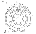
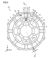
- FIG. 1 is a schematic plan view showing a planar aspect of a torque detection device according to a first embodiment. It is a schematic sectional drawing of the part which follows the II-II line of FIG.
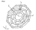
- FIG. 3 is a schematic perspective view for more clearly showing the above-mentioned X direction, Y direction, and Z direction in FIGS. 1 and 2 as an X axis, a Y axis, and a Z axis, respectively.
- FIG. 5 is a schematic view showing an example of the configuration of the magnetic target 8 and the magnetic sensor 7 in FIGS. 1 to 3 in more detail.
- FIG. 6 is a schematic plan view displaying dimensions in the width direction intersecting the extending direction of the portions of the first beam and the second beam of FIG. 1 in particular; FIG.
- FIG. 6 is a schematic cross-sectional view of a portion along the line VI-VI of FIG. 5;
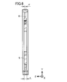
- FIG. 7 is a schematic cross-sectional view of a portion along the line VII-VII in FIG. 5; It is a schematic sectional drawing of the part which follows the VIII-VIII line of FIG. In Embodiment 1, it is a graph which shows the relationship between the torque and magnetic quantity change amount which are known beforehand.
- FIG. 10 is a schematic plan view showing a plane aspect of a torque detection device according to Embodiment 2.
- FIG. 11 is a schematic cross-sectional view of a portion along line XI-XI of FIG. 10;
- FIG. 11 is a schematic plan view showing dimensions in the width direction intersecting the extending direction of the portions of the first beam and the second beam in FIG. 10 in particular.
- FIG. 13 is a schematic cross-sectional view of a portion along the line XIII-XIII of FIG. 12;
- FIG. 13 is a schematic plan view showing a plane aspect of a torque detection device according to a third embodiment.
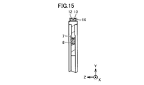
- FIG. 15 is a schematic cross-sectional view of a portion along line XV-XV of FIG. 14;
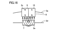
- FIG. 17 is a schematic view showing in more detail another example different from FIG. 4 of the configuration of the magnetic target 8 and the magnetic sensor 7 of the torque detection device according to Embodiment 4.
- FIG. 1 is a schematic plan view showing a planar aspect of the torque detection device according to the present embodiment.
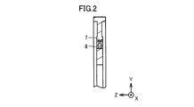
- FIG. 2 is a schematic cross-sectional view of a portion along line II-II in FIG.
- FIG. 3 is a schematic perspective view for more clearly showing the above-mentioned X direction, Y direction, and Z direction in FIGS. 1 and 2 as an X axis, a Y axis, and a Z axis, respectively.
- torque detection device 1 ⁇ / b> A of the present embodiment includes inner ring 2, middle ring 3, outer ring 4, first beam 5, and second beam 6. , Magnetic sensor 7 and magnetic target 8 are mainly provided.
- the inner ring 2 is an annular portion disposed at the innermost side in a plan view.
- the inner side of the inner ring 2 is a circular hollow portion.
- a rotary shaft of a motor can be inserted into a circular hollow portion of the inner ring 2.
- the inner ring 3 is an annular portion disposed on the outer peripheral side of the inner ring 2 at a distance from the inner ring 2.
- the outer ring 4 is an annular portion disposed on the outer peripheral side of the middle ring 3 at a distance from the inner ring 2.
- On the outer peripheral surface of the outer ring 4 for example, an annular object rotating by using a rotational force of a motor is inserted and fixed.
- the torque detection device 1A Since each of these members has an annular shape, the torque detection device 1A has a substantially circular planar shape as a whole. However, the shape on the inner peripheral side of the inner ring 2 and the shape on the outer peripheral side of the outer ring 4 can be appropriately changed according to the shape of the rotary shaft fixed to the inner ring 2 and the shape of the object fixed to the outer ring 4 . Therefore, the entire torque detection device 1A can be changed in any plane shape such as a square.
- the first beam 5 extends in the radial direction of the circular shape of the inner ring 2 and the middle ring 3 so as to connect the inner ring 2 and the middle ring 3. More specifically, the inner ring 2 includes the inner ring outer diameter surface 2a as the outermost surface, and the middle ring 3 includes the middle wheel inner diameter surface 3a as the innermost surface. The first beam 5 extends in the circular radial direction of the inner ring 2 and the middle ring 3 so as to connect the inner ring outer diameter surface 2 a and the middle ring inner diameter surface 3 a. A plurality of first beams 5 are arranged at intervals in the circumferential direction of the circular shape, and eight first beams 5 are disposed as an example in FIG. 1. The first beam 5 is fixed to the inner ring 2 and the middle ring 3. In other words, the first beam 5 does not move freely relative to the inner ring 2 and the middle ring 3.
- the second beam 6 extends in the radial direction of the circular shape of the middle ring 3 and the outer ring 4 so as to connect the middle ring 3 and the outer ring 4. More specifically, the middle ring 3 includes the middle ring outer diameter surface 3b as the outermost surface, and the outer ring 4 includes the outer ring inner diameter surface 4a as the innermost surface. The second beam 6 extends in the radial direction of the circular shape of the middle ring 3 and the outer ring 4 so as to connect the middle ring outer diameter surface 3 b and the outer ring inner diameter surface 4 a.
- a plurality of second beams 6 are disposed spaced apart from one another in the circumferential direction of the circular shape, and eight second beams 6 are disposed as an example in FIG. 1.
- the second beam 6 is fixed to the middle ring 3 and the outer ring 4. In other words, the second beam 6 does not move freely with respect to the middle wheel 3 and the outer wheel 4.
- the first beam 5 and the second beam 6 are preferably arranged so as not to align on a straight line in plan view.
- the second beams 6 in FIG. 1 are arranged to have a pair of ones extending in a direction substantially coinciding with the X direction and the Y direction
- the first beams 5 are such All are arranged to extend in a direction having a constant angle with respect to the X direction and the Y direction.
- the magnetic target 8 is fixed to the inner ring 2 in FIGS. 1 and 2. More specifically, an inner ring convex portion 2 c is formed on a part of the inner ring outer diameter surface 2 a of the inner ring 2 toward the outer peripheral side.
- the inner ring convex portion 2 c is formed, for example, on one inner ring outer diameter surface 2 a of the inner ring outer diameter surfaces 2 a divided into eight in the circumferential direction by eight first beams 5.
- a flat surface concave portion 2e is further formed on a tip end flat surface 2d which is a tip surface of the inner ring convex portion 2c, that is, a flat surface on the outermost side.
- the flat surface recess 2e is formed toward the inner peripheral side.
- the magnetic target 8 is disposed so as to be fixed to the flat surface concave portion 2e.
- the magnetic target 8 is a mechanism that generates a magnetic field as described later.
- the magnetic sensor 7 is fixed to the middle wheel 3 in FIGS. 1 and 2. More specifically, a middle wheel recess 3c is formed on a part of the middle wheel inner diameter surface 3a of the middle wheel 3 toward the outer peripheral side. The magnetic sensor 7 is disposed so as to be fixed to the middle wheel recess 3c. The magnetic sensor 7 is directly fixed to the middle wheel recess 3c. However, the magnetic sensor 7 may be mounted on a printed circuit board (not shown), and the printed circuit board may be fixed on a flat surface (not shown) provided on a part of the surface of the middle ring inner diameter surface 3a.
- the magnetic sensor 7 is a mechanism that detects a magnetic field generated by the magnetic target 8. In order to detect the magnetic field, the magnetic target 8 and the magnetic sensor 7 face each other in the radial direction.
- the torque detection device 1A having the above configuration calculates the torque applied to the inner ring 2 in accordance with the amount of magnetism detected by the magnetic sensor 7. Next, the configuration of such a torque detection device 1A will be described in more detail using FIGS. 4 to 8. FIG.
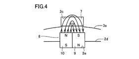
- FIG. 4 is a schematic diagram showing an example of the configuration of the portions of the magnetic target 8 and the magnetic sensor 7 in FIGS. 1 to 3 in more detail.
- the magnetic target 8 includes two permanent magnets 9 and 10.
- the permanent magnets 9 and 10 are magnetized so as to have a pair of N and S poles in the longitudinal direction, ie, the vertical direction in FIG.
- the two permanent magnets 9 and 10 are disposed adjacent to each other and adhered.
- one and the other of the two permanent magnets 9 and 10 are bonded so that their polarities are opposite to each other. That is, it is preferable that one N pole and the other S pole of the two permanent magnets 9 and 10 be arranged in a direction along the circumferential direction of the inner ring 2, the outer ring 4 and the like. Thus, in the magnetic field generated by the magnetic target 8, magnetic lines of force having components along the circumferential direction are formed from the N pole of the permanent magnet 9 toward the S pole of the permanent magnet 10.
- the permanent magnets 9 and 10 used as the magnetic target 8 are preferably any one selected from the group consisting of neodymium magnets, samarium cobalt magnets, alnico magnets, and ferrite magnets.
- the magnetic sensor 7 is a bonded portion (the boundary between the permanent magnet 9 and the permanent magnet 10 in FIG. 4) in which the two permanent magnets 9 and 10 are bonded to each other particularly when no torque is applied to the inner ring 2 by rotational displacement.
- any one selected from the group consisting of a magnetoresistive element (MR sensor), a magnetic impedance element (MI sensor), and a Hall element can be used.
- MR sensor magnetoresistive element
- MI sensor magnetic impedance element
- Hall element it is more preferable to use a Hall IC in which a Hall element and an electric circuit such as an amplifier circuit are integrated, and in this case, the number of post-mounting circuits can be reduced.
- the magnetic sensor 7 more preferably has a program function, which makes it easy to set the output voltage. If the magnetic sensor 7 has a program function, the linearity and sensitivity of the output from the magnetic sensor 7 can be corrected.
- the magnetic sensor 7 one having a temperature compensation circuit may be used. In this way, temperature compensation becomes possible without providing an external circuit.
- FIG. 5 is a schematic plan view showing dimensions in the width direction intersecting the extending direction of the portions of the first beam 5 and the second beam 6 in FIG. 1 in particular.
- FIG. 6 is a schematic cross-sectional view showing the dimensions in the thickness direction of the first beam 5 and the second beam 6 of FIG. 2 in particular, that is, the dimensions in the direction perpendicular to the sheet of
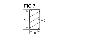
- FIG. 7 is a schematic cross-sectional view in the direction intersecting the extending direction of the first beam 5
- FIG. 8 is a schematic cross-sectional view in the direction intersecting the extending direction of the second beam 6. As shown in FIG.
- the dimension b is larger than the dimension a. More specifically, the dimension b is preferably, for example, 1.2 to 2 times the dimension a, and more preferably 1.5 to 1.8 times.
- a dimension c in a thickness direction (a left-right direction in FIG. 6 and a direction perpendicular to the sheet of FIG.
- the dimension c is larger than the dimension d. More specifically, the dimension c is preferably, for example, 1.2 to 2 times the dimension d, and more preferably 1.5 to 1.8 times.
- the dimensions (lengths) of the first beam 5 and the second beam 6 in the radial direction (direction extending radially from the center of the circle such as the inner ring 2 to the outer periphery) intersecting both the thickness direction and the width direction ) can be determined arbitrarily.
- the first beam 5 and the second beam 6 have the same dimensions in this direction.
- the first beam 5 has a larger dimension in one direction (here, the thickness direction) than the second beam 6 and relates to another direction (here, the width direction) intersecting the one direction. Small size.
- the cross section in the direction intersecting the extending direction of the first beam 5 (shown in FIG. 7) and the direction intersecting the extending direction of the second beam 6 has a shape different from each other, and in particular, the two are non-similar to each other.
- the horizontal dimension in FIG. 7 indicates the width a of the first beam 5 in FIG. 5, and the vertical dimension indicates the thickness c of the first beam 5.
- the horizontal dimension in FIG. 8 indicates the width b of the second beam 6 in FIG. 5, and the vertical dimension indicates the thickness d of the second beam 6 in FIG.
- an annular object that is rotated by using, for example, the rotational shaft of a motor fixed to the inner ring 2 and the rotational force of a motor fixed to the outer ring 4 is rotated.
- a torque is applied between the inner ring 2 and the outer ring 4 by these rotations.
- the first beam 5 connecting the inner ring 2 and the middle ring 3 and the second beam 6 connecting the middle ring 3 and the outer ring 4 are deformed to generate rotational displacement. Due to this rotational displacement, the permanent magnets 9 and 10 of the magnetic target 8 transmit to the magnetic sensor 7 and the amount of magnetism detected by the magnetic sensor 7 changes.
- the torque is calculated from the amount of change in the amount of magnetism detected by the magnetic sensor 7.
- the torque is only calculated from the change of the magnetic amount due to the rotational displacement. For this reason, for example, the change of the electrical resistance value of a plurality of gauges laid on the beam is obtained from expansion and contraction due to rotational displacement of the beam, the signal of the sensor output voltage is calculated therefrom, and the torque is calculated therefrom.
- the torque can be calculated in a simple process. That is, in the torque detection device 1A, the processing circuit for calculating the torque is simplified.
- a cross section in a direction intersecting the extending radial direction of the first beam 5 (see FIG. 7) and a cross section in a direction intersecting the extending radial direction of the second beam 6 (FIG. 8 (See reference) are dissimilar to each other.
- the first beam 5 has a larger dimension in one direction (here, thickness direction) than the second beam 6, and another direction (here, width direction) intersecting the one direction. The dimensions regarding are small.
- the first beam 5 and the second beam 6 can be easily deformed with respect to the torque in the different directions. It becomes. That is, one of the first beam 5 or the second beam 6 has lower rigidity in the direction of detecting the amount of magnetism as compared to the other of the first beam 5 or the second beam 6, and the direction of detecting the amount of magnetism The rigidity in the other direction is higher.
- the first beam 5 has a smaller dimension in the width direction than the second beam 6.
- the width direction corresponds to the direction along the circumferential direction, and is along the direction of rotating the inner ring 2 and the outer ring 4 around the Z axis.
- the rigidity of the first beam 5 with respect to the rotational torque around the Z axis is lower than that of the second beam 6, and the torque detection device 1A is easy to rotate.
- the first beam 5 has a larger dimension in the thickness direction than the second beam 6.
- the thickness direction is along the direction in which the inner ring 2 and the outer ring 4 are rotated around the X axis and the Y axis. Therefore, the torque detection device 1A has high rigidity with respect to rotational torque around the X axis and the Y axis as compared with the second beam 6, and the torque detection device 1A is difficult to rotate.
- a magnetic target 8 is installed on the inner race 2 and a magnetic sensor 7 is installed on the middle race 3. Therefore, only the torque corresponding to the rotational displacement of the inner ring 2 is detected, and the torque corresponding to the rotational displacement of the outer ring 4 is not detected. Since rotational displacement occurs due to rotation of the rotation shaft of the motor extending in the Z-axis direction, it is necessary to measure the rotational torque around the Z-axis of the inner ring 2. In this measurement, it is desirable that the rotational torque corresponding to the displacement around the X axis and the Y axis of the inner ring 2 is a noise, and thus it is excluded.
- the first beam 5 connected to the inner ring 2 detects a torque (rotation around the Z axis) as compared to the second beam 6 not directly connected to the inner ring 2 Rigidity in the direction) is low, and rigidity in directions (rotation directions around the X axis and Y axis) other than the direction in which the torque is detected is high.
- a torque about the X axis or a Y axis is applied, the second beam 6 having low rigidity with respect to the torque in this direction is largely deformed, so the influence on the deformation of the first beam 5 is reduced. be able to.
- the present embodiment it is possible to detect only the necessary torque around the rotation axis with high accuracy by the simple processing circuit and the simple configuration.
- the effect of reducing the detection of rotational displacement other than around the Z-axis by members other than the desired member of the inner ring 2 or the outer ring 4 is realized by having three ring members including the middle ring 3 Be done.
- the magnetic fluxes from the permanent magnets 9 and 10 are indicated by a plurality of arrows, the direction of the arrow indicates the direction of the magnetic flux, and the density of the arrow indicates the density of the magnetic flux.
- the direction of the arrow indicates the direction of the magnetic flux
- the density of the arrow indicates the density of the magnetic flux.
- the relative displacement between the magnetic target 8 and the magnetic sensor 7 slightly changes due to the rotational displacement of the inner ring 2 around the Z axis, and the amount of magnetism detected by the magnetic sensor 7 changes rapidly accordingly.
- the magnetic amount changes particularly greatly due to the minute change of the position.
- the magnetic sensor 7 is disposed at a position facing the bonding portion of the permanent magnets 9 and 10, so that the magnetic target 8 and the magnetic sensor 7 Although only such displacement occurs, the amount of magnetism due to rotational displacement can be accurately detected, and torque can be calculated from the detected amount of magnetism.
- the positional relationship between the magnetic target 8 and the magnetic sensor 7 changes with respect to the applied torque, and the amount of magnetism detected by the magnetic sensor 7 changes.
- the torque applied to the torque detection device 10 is calculated from the amount of change in the amount of magnetism detected by the magnetic sensor 7.
- the amount of change in the amount of magnetism detected by the magnetic sensor 7 is detected as a voltage from the magnetic sensor 7. Therefore, the output voltage of the magnetic sensor 7 can be regarded as the change amount of the magnetic amount of the magnetic sensor 7.
- the value of the torque of the torque detection device 10 is calculated by the relationship between the torque and the amount of change in the amount of magnetism that is known in advance.
- the relationship between the torque and the amount of change in magnetic quantity can be obtained, for example, by a test. That is, a torque known in advance is applied to the torque detection device 10, and the amount of change in the amount of magnetism at that time is measured. Thereby, for example, a torque calculation table as shown in FIG. 9 can be created.
- the graph of FIG. 9 shows the relationship between the torque and the amount of change in the amount of magnetism known in advance.
- the horizontal axis of FIG. 9 indicates the applied torque, and the vertical axis indicates the amount of change of the magnetic amount when the torque is applied.
- a Hall IC or the like be used for the magnetic sensor 7, and one having a program function as described above be used for the Hall IC. In this way, the torque applied to the torque detection device 10 can be calculated from the voltage output from the magnetic sensor 7.
- the torque applied to the torque detection device 10 may be accurately calculated. Can. However, if the relationship between the torque applied to the torque detection device 10 and the amount of change in the magnetic amount is nonlinear as shown by the dotted line in FIG. 9, for example, the torque applied to the torque detection device 10 is accurately It can not be calculated. Therefore, a correction straight line is obtained using a plurality of values (a plurality of coordinate points not shown in FIG. 9 but which can be shown on the graph but not shown in FIG. 9) from the relationship between torque and amount of change in the non-linear data. Is preferred. In this way, the torque can be accurately calculated from the correction straight line.
- the member positioned on the back side (the opposite side in the radial direction) of the magnetic sensor 7 as viewed from the magnetic target 8 is more preferably formed of a ferromagnetic material such as an iron-based material. In this way, the density of the magnetic flux passing through the magnetic sensor 7 can be effectively increased.
- the inner ring 2, the middle ring 3, the outer ring 4, the first beam 5, and the second beam 6 be integrally formed.
- the respective members can be formed in a simpler process, so that the manufacturing cost can be reduced.
- at least the first beam 5 and the second beam 6 are formed of elastic members. Thus, even after the rotation site is added, the member can be returned to its original position by releasing it.
- FIG. 10 is a schematic plan view showing a planar aspect of the torque detection device according to the present embodiment.
- FIG. 11 is a schematic cross-sectional view of a portion along line XI-XI in FIG.
- torque detection device 1B of the present embodiment has basically the same configuration as torque detection device 1A. Therefore, the same components are denoted by the same reference numerals, and the description thereof will not be repeated. However, in the torque detection device 1B, the installation mode of the magnetic target 8 and the magnetic sensor 7 is different.
- the magnetic target 8 is fixed to the middle wheel 3 in FIGS. 10 and 11. More specifically, a middle wheel convex portion 3 f is formed on a part of the middle wheel outer diameter surface 3 b of the middle wheel 3 toward the outer peripheral side.
- the middle ring convex portion 3 f is formed, for example, on one middle wheel outer diameter surface 3 b of the middle wheel outer diameter surfaces 3 b divided into eight in the circumferential direction by eight second beams 6.
- a flat surface concave portion 3e is further formed on a tip end flat surface 3d which is a tip surface of the middle ring convex portion 3f, that is, a flat surface on the outermost side.
- the flat surface recess 3e is formed toward the inner peripheral side.
- a magnetic target 8 is disposed so as to be fixed to the flat surface recess 3e.
- the magnetic sensor 7 is fixed to the outer ring 4 in FIGS. 10 and 11. More specifically, an outer ring recessed portion 4 c is formed on a part of the outer ring inner diameter surface 4 a of the outer ring 4 toward the outer peripheral side. A magnetic sensor 7 is disposed so as to be fixed to the outer ring recess 4c. The magnetic sensor 7 is directly fixed to the outer ring recess 4c. However, the magnetic sensor 7 may be mounted on a printed circuit board (not shown), and the printed circuit board may be fixed on a flat surface (not shown) provided on a part of the surface of the outer ring inner diameter surface 4a.
- the torque detection device 1B having the above configuration calculates the torque applied to the outer ring 4 according to the amount of magnetism detected by the magnetic sensor 7.
- FIG. 12 is a schematic plan view showing dimensions in the width direction intersecting the extending direction of the portions of the first beam 5 and the second beam 6 in FIG. 10 in particular.
- FIG. 13 is a schematic cross-sectional view showing the dimensions in the thickness direction of the first beam 5 and the second beam 6 in FIG. 11, that is, the dimensions in the direction perpendicular to the paper surface of FIG.
- the dimension a in the width direction intersecting the extending direction of the first beam 5 intersects the extending direction of the second beam 6 It is larger than the dimension b in the width direction. More specifically, the dimension a is preferably, for example, 1.2 to 2 times the dimension b, and more preferably 1.5 to 1.8 times.
- the dimension c in the thickness direction intersecting the dimension in the width direction of the first beam 5 intersects the dimension in the width direction of the second beam 6.
- the dimension d in the thickness direction is larger. More specifically, the dimension d is preferably, for example, 1.2 to 2 times the dimension c, and more preferably 1.5 to 1.8 times.
- the first beam 5 has a larger dimension in one direction (here, the width direction) than the second beam 6 and relates to another direction (here, the thickness direction) intersecting the one direction. Small size.
- the functions and effects of the torque detection device 1B having the above configuration are basically the same as the functions and effects of the torque detection device 1A, so the description of the same functions and effects will not be repeated. That is, one of the first beam 5 or the second beam 6 has lower rigidity in the torque detection direction than the other of the first beam 5 or the second beam 6, and the one other than the torque detection direction The rigidity in the direction increases. However, here, specifically, the second beam 6 has a smaller dimension in the width direction than the first beam 5. Therefore, in the torque detection device 1B, the rigidity of the second beam 6 with respect to the rotational torque around the Z-axis is lower than that of the first beam 5, and the torque detection device 1B is easy to rotate.
- the second beam 6 has a larger dimension in the thickness direction than the first beam 5. Therefore, in the torque detection device 1B, the rigidity of the second beam 6 is higher than that of the first beam 5 with respect to the rotational torque around the X axis and the Y axis, and is difficult to rotate.
- the magnetic target 8 is installed on the middle wheel 3 and the magnetic sensor 7 is installed on the outer ring 4. Therefore, only torque corresponding to rotational displacement of the outer ring 4 with respect to the middle wheel 3 is detected, and torque due to rotational displacement of the inner ring 2 with respect to the middle wheel 3 is not detected.
- the rigidity in the torque detection direction (rotational direction around Z axis) is lower
- the rigidity in directions (rotation directions around the X axis and Y axis) other than the direction of detecting
- FIG. 14 is a schematic plan view showing a planar aspect of the torque detection device according to the present embodiment.
- FIG. 15 is a schematic cross-sectional view of a portion along line XV-XV of FIG.
- torque detection apparatus 1C of the present embodiment has basically the same configuration as torque detection apparatus 1A. Therefore, the same components are denoted by the same reference numerals, and the description thereof will not be repeated.
- the torque detection device 1C further includes a signal processing unit 14 including a power supply unit 12 and a transmission unit 13 for transmitting a torque signal as a change in magnetic amount obtained from the magnetic sensor 7 in the torque detection device 1A.
- the signal processing unit 14 is for calculating a torque according to the amount of magnetism detected by the magnetic sensor 7.
- the torque detection device 1B may further include the signal processing unit 14 configured as described above.
- the power supply unit 12 may be either a battery or a self-generating unit.
- the transmission unit 13 transmits, for example, wirelessly the torque signal obtained from the magnetic sensor 7 but may not be wireless.
- an arithmetic processing unit (CPU) may be mounted that converts a signal of the magnetic amount of the magnetic sensor 7 into a torque value.
- Signal processing unit 14 is fixed to, for example, outer ring outer diameter surface 4 b of outer ring 4, but may be fixed to another portion.
- the torque detection device 1C can process the signal of the magnetic quantity of the magnetic sensor 7 more efficiently.
- Embodiment 4 In each of the torque detection devices of the above-described embodiments, the magnetic target 8 is fixed to a member disposed on the inner peripheral side of the magnetic sensor 7. However, in the torque detection device of any of the above-described embodiments, the magnetic target 8 may be fixed to a member disposed on the outer peripheral side of the magnetic sensor 7. Specifically, for example, with reference to FIG. 16, this configuration is basically the same as the configuration shown in FIG. However, as shown in FIG. 16, for example, in the torque detection device 1A of FIG. 1, the magnetic target 8 may be fixed to the middle ring 3 and the magnetic sensor 7 may be fixed to the inner ring 2. Although not shown, in the torque detection device 1B of FIG.
- the magnetic target 8 may be fixed to the outer ring 4 and the magnetic sensor 7 may be fixed to the middle ring 3.
- Such a configuration in which the magnetic target 8 is disposed on the outer peripheral side of the magnetic sensor 7 may be applied to the torque detection device 1C of FIG. If all the examples of the above each embodiment are put together, the magnetic target 8 will be fixed to any one of the inner ring 2 and the middle ring 3, or any one of the middle ring 3 and the outer ring 4.
- a magnetic sensor 7 for detecting a magnetic field generated by the magnetic target 8 is fixed to any one of the inner ring 2 and the middle ring 3 or the other one of the middle ring 3 and the outer ring 4.
- the magnetic target 8 and the magnetic sensor 7 face each other in the radial direction.
- 1A, 1B, 1C torque detection device 2 inner ring, 2a inner ring outer diameter surface, 2c inner ring convex portion, 2d, 3d tip flat surface, 2e, 3e flat surface recess, 3 middle ring, 3a middle ring inner diameter surface, 3b middle Ring outer diameter surface, 3c middle ring concave portion, 3f middle ring convex portion, 4 outer ring, 4a outer ring inner diameter surface, 4b outer ring outer diameter surface, 4c outer ring concave portion, 5 first beam, 6 second beam, 7 magnetic sensor, 8 magnetic target, 9, 10 permanent magnet, 12 power supply unit, 13 transmission unit, 14 signal processing unit.
Landscapes
- Physics & Mathematics (AREA)
- Electromagnetism (AREA)
- General Physics & Mathematics (AREA)
- Power Steering Mechanism (AREA)
Abstract
複合的なトルクが入力されても、回転軸周り方向のトルクのみを簡素に検出し、ノイズとしてのトルクを除去可能なトルク検出装置を提供する。トルク検出装置は、内輪(2)と、中輪(3)と、外輪(4)と、第1の梁(5)と、第2の梁(6)と、磁気ターゲット(8)と、磁気センサ(7)とを備える。第1の梁(5)は、内輪(2)および中輪(3)を連結するように径方向に延びる弾性部材からなる。第2の梁(6)は、中輪(3)および外輪(4)を連結するように径方向に延びる弾性部材からなる。磁気ターゲット(8)は内輪(2)に、磁気センサ(7)は中輪(3)に、互いに対向するように固定される。磁気センサ(7)が検出する磁気量の変化に応じて内輪(2)または外輪(4)に加わるトルクが算出される。
Description
本発明はトルク検出装置に関し、特に、回転軸などに加わるトルクを測定するために用いるトルク検出装置に関するものである。
たとえば特開2009-288198号公報(特許文献1)には、回転軸などに加わるトルクを計測するトルク計測装置が開示されている。このトルク計測装置は、歪みが起きる主の部分としての主起歪部位と、歪みが起きる副の部分としての補助起歪部位とを備えている。主起歪部位は内輪と外輪との回転によるトルクに応じて、主に内輪および外輪の回転軸周り方向に変位する部分である。補助起歪部位は主起歪部位の一方の端部から内輪および外輪の回転方向すなわち主起歪部位の周方向に延びる環状を有している。補助起歪部位は、主起歪部位の回転軸周り方向以外の方向の変位成分を除去する。補助起歪部位の上記作用により、主起歪部位が本来歪み変位すべき方向以外の方向に歪むことが抑制される。
特開2009-288198号公報のトルク計測装置においては、主起歪部位に1組以上(たとえば4組)の歪みゲージを貼設することで、それぞれの歪みゲージの電気抵抗値の変化からセンサ出力電圧の信号を得ることができる。そしてその出力電圧の信号から、トルクが高精度かつ高感度に計測される。しかし特開2009-288198号公報のトルク計測装置は、主起歪部位の伸縮による歪曲から各組の歪みゲージの電気抵抗値の変化を求め、そこからセンサ出力電圧の信号を演算し、さらにトルクを演算処理する。このため当該トルク計測装置は、複数の歪みゲージから検出される値を複雑な工程で演算処理する必要がある。つまり当該トルク計測装置は、処理回路が複雑であることが想定される。
本発明は以上の課題に鑑みなされたものであり、その目的は、複合的なトルクが入力されても、回転軸周り方向のトルクのみを簡素に検出可能なトルク検出装置を提供することである。
本発明のトルク検出装置は、内輪と、中輪と、外輪と、第1の梁と、第2の梁と、磁気ターゲットと、磁気センサとを備える。第1の梁は、内輪および中輪を連結するように径方向に延びる弾性部材からなる。第2の梁は、中輪および外輪を連結するように径方向に延びる弾性部材からなる。磁気ターゲットと磁気センサとは、それぞれ内輪および中輪のいずれか一方および他方、または中輪および外輪のいずれか一方および他方に、互いに対向するように固定される。磁気センサが検出する磁気量の変化に応じて内輪または外輪に加わるトルクが算出される。
本発明によれば、磁気センサが検出する磁気量の変化に応じて内輪または外輪に加わるトルクが算出される。このため主起歪部位に貼設された複数の歪みゲージの電気抵抗値の変化からセンサ出力電圧の信号を演算するような煩雑な工程を割愛することができ、簡素な処理により、必要な回転軸周り方向のトルクのみを検出することができる。
以下、本発明の実施の形態について図に基づいて説明する。
(実施の形態1)
まず本実施の形態のトルク検出装置について、図1~図8を用いて説明する。なお、説明の便宜のため、X方向、Y方向、Z方向が導入されている。図1は本実施の形態に係るトルク検出装置の平面態様を示す概略平面図である。図2は図1のII-II線に沿う部分の概略断面図である。図3は図1および図2における上記のX方向、Y方向、Z方向をそれぞれX軸、Y軸、Z軸としてより明確に示すための概略斜視図である。図1、図2および図3を参照して、本実施の形態のトルク検出装置1Aは、内輪2と、中輪3と、外輪4と、第1の梁5と、第2の梁6と、磁気センサ7と、磁気ターゲット8とを主に備えている。
(実施の形態1)
まず本実施の形態のトルク検出装置について、図1~図8を用いて説明する。なお、説明の便宜のため、X方向、Y方向、Z方向が導入されている。図1は本実施の形態に係るトルク検出装置の平面態様を示す概略平面図である。図2は図1のII-II線に沿う部分の概略断面図である。図3は図1および図2における上記のX方向、Y方向、Z方向をそれぞれX軸、Y軸、Z軸としてより明確に示すための概略斜視図である。図1、図2および図3を参照して、本実施の形態のトルク検出装置1Aは、内輪2と、中輪3と、外輪4と、第1の梁5と、第2の梁6と、磁気センサ7と、磁気ターゲット8とを主に備えている。
内輪2は、平面視における最も内側に配置される円環状の部分である。内輪2の更に内側は円形の空洞部分となっている。内輪2の円形の空洞部分にはたとえばモータの回転軸などを挿入することができる。中輪3は、内輪2の外周側に、内輪2と互いに間隔をあけて配置される円環状の部分である。外輪4は、中輪3の外周側に、内輪2と互いに間隔をあけて配置される円環状の部分である。外輪4の外周面にはたとえばモータの回転力を用いて回転する円環状の対象物が嵌挿され固定される。これらの各部材が円環状を有するため、トルク検出装置1Aは、全体がほぼ円形の平面形状を有している。ただし内輪2に固定される回転軸の形状、および外輪4に固定される対象物の形状に応じて、内輪2の内周側の形状および外輪4の外周側の形状を適宜変更することができる。このためトルク検出装置1Aの全体はたとえば四角形など任意の平面形状を変更することができる。
第1の梁5は、内輪2と中輪3とを連結するように、内輪2および中輪3の円形状の径方向に延びている。より具体的には、内輪2は最も外周側の面としての内輪外径面2aを含み、中輪3は最も内周側の面としての中輪内径面3aを含んでいる。第1の梁5は、内輪外径面2aと中輪内径面3aとを連結するように、内輪2および中輪3の円形状の径方向に延びている。第1の梁5は、当該円形状の周方向に関して、互いに間隔をあけて複数配置されており、図1においては一例として8つの第1の梁5が配置されている。第1の梁5は内輪2および中輪3に固定されている。言い換えれば第1の梁5は内輪2および中輪3に対して自由に動くことはない。
また第2の梁6は、中輪3と外輪4とを連結するように、中輪3および外輪4の円形状の径方向に延びている。より具体的には、中輪3は最も外周側の面としての中輪外径面3bを含み、外輪4は最も内周側の面としての外輪内径面4aを含んでいる。第2の梁6は、中輪外径面3bと外輪内径面4aとを連結するように、中輪3および外輪4の円形状の径方向に延びている。第2の梁6は、当該円形状の周方向に関して、互いに間隔をあけて複数配置されており、図1においては一例として8つの第2の梁6が配置されている。第2の梁6は中輪3および外輪4に固定されている。言い換えれば第2の梁6は中輪3および外輪4に対して自由に動くことはない。
図1に示すように、第1の梁5と第2の梁6とは、平面視において一直線上に並ばないように配置されることが好ましい。言い換えれば、図1において第2の梁6はX方向およびY方向にほぼ一致する方向に延びるものを1対ずつ有するように配置されているのに対し、第1の梁5はそのようなものを有さず、すべてX方向およびY方向に対して一定の角度を有する方向に延びるように配置されている。
磁気ターゲット8は、図1および図2においては、内輪2に固定されている。より具体的には、内輪2の内輪外径面2aの一部には内輪凸部2cが、外周側に向けて形成されている。内輪凸部2cはたとえば8つの第1の梁5により周方向に関して8つに区画された内輪外径面2aのうちの1つの内輪外径面2aに形成されている。この内輪凸部2cの先端面すなわち最も外周側の平坦な面である先端部平坦面2dには、さらに平坦面凹部2eが形成されている。平坦面凹部2eは、内周側に向けて形成されている。この平坦面凹部2eに固定されるように、磁気ターゲット8が配置されている。磁気ターゲット8は後述するように磁場を発生する機構である。
磁気センサ7は、図1および図2においては、中輪3に固定されている。より具体的には、中輪3の中輪内径面3aの一部には中輪凹部3cが、外周側に向けて形成されている。この中輪凹部3cに固定されるように、磁気センサ7が配置されている。磁気センサ7は、中輪凹部3cに直接固定される。ただし磁気センサ7は、図示されないプリント基板上に実装され、そのプリント基板が中輪内径面3aの表面の一部に設けられた図示されない平坦面上に固定されてもよい。
磁気センサ7は、磁気ターゲット8が発生する磁場を検出する機構である。磁場を検出するために、磁気ターゲット8および磁気センサ7は、径方向に関して互いに対向する。以上のような構成を有するトルク検出装置1Aは、磁気センサ7が検出する磁気量に応じて内輪2に加わるトルクを算出する。次に図4~図8を用いて、そのようなトルク検出装置1Aの構成についてより詳細に説明する。
図4は、図1~図3における磁気ターゲット8および磁気センサ7の部分の構成の一例をより詳細に示す概略図である。図4を参照して、磁気ターゲット8は、2つの永久磁石9,10を含んでいる。永久磁石9,10は長手方向すなわち図4の上下方向に1対のN極およびS極を有するように磁化されている。これら2つの永久磁石9,10は、互いに隣り合うように配置され接着されている。ここでは2つの永久磁石9,10は、トルク検出装置1Aにより検査される回転軸などの回転方向すなわち図1~図3の内輪2、外輪4などの円周方向に沿うように並ぶことが好ましい。また2つの永久磁石9,10の一方および他方は互いに極性が背反するように接着される。すなわち2つの永久磁石9,10の一方のN極と他方のS極とが上記の内輪2、外輪4などの円周方向に沿う方向に並ぶように配列されることが好ましい。これにより、磁気ターゲット8の発生する磁場では、永久磁石9のN極から永久磁石10のS極に向けて、上記円周方向に沿う成分を有する磁力線が形成される。
磁気ターゲット8として用いる永久磁石9,10は、ネオジウム磁石、サマリウムコバルト磁石、アルニコ磁石、フェライト磁石からなる群から選択されるいずれかであることが好ましい。
磁気センサ7は、特に内輪2などに回転変位によるトルクが加わっていない状態において、2つの永久磁石9,10が互いに接着される接着部(図4における永久磁石9と永久磁石10との境界)が少なくとも磁気センサ7と径方向に関して対向するように配置されている。つまり図4中の永久磁石9と永久磁石10との境界としての上下方向に延びる直線部分は、図4の上下方向すなわち径方向に関して磁気センサ7と対向している。
磁気センサ7としては、磁気抵抗素子(MRセンサ)、磁気インピーダンス素子(MIセンサ)、ホール素子からなる群から選択されるいずれかを用いることができる。ただし磁気センサ7としては、ホール素子と増幅回路などの電気回路とを一体化したホールICが用いられることがより好ましく、このようにすれば後付け回路を少なくすることができる。
また磁気センサ7はプログラム機能を有していることがより好ましく、このようにすれば出力電圧の設定が容易になる。また磁気センサ7がプログラム機能を有していれば、磁気センサ7からの出力の直線性および感度を補正することができる。
さらに磁気センサ7としては、温度補償回路を有するものが用いられてもよい。このようにすれば、外付けの回路を設けなくても温度補償が可能となる。
図5は図1の特に第1の梁5および第2の梁6の部分の延びる方向に交差する幅方向の寸法を表示する概略平面図である。図6は図2の特に第1の梁5および第2の梁6の厚み方向の寸法すなわち図5の紙面垂直方向の寸法を表示する概略断面図である。また図7は第1の梁5が延びる方向に交差する方向での概略断面図であり、図8は第2の梁6が延びる方向に交差する方向での概略断面図である。
図5を参照して、第1の梁5の延びる方向に交差する幅方向(円周方向に沿う方向)の寸法aと、第2の梁6の延びる方向に交差する幅方向(円周方向に沿う方向)の寸法bとは異なっている。トルク検出装置1Aにおいては、寸法aよりも寸法bの方が大きい。より具体的には、寸法bは寸法aのたとえば1.2倍以上2倍以下であることが好ましく、1.5倍以上1.8倍以下であることがより好ましい。また図6を参照して、第1の梁5の上記幅方向の寸法に交差する厚み方向(図6の左右方向であり図5の紙面に垂直方向)の寸法cと、第2の梁6の上記幅方向の寸法に交差する厚み方向(図6の左右方向であり図5の紙面に垂直方向)の寸法dとは異なっている。トルク検出装置1Aにおいては、寸法dよりも寸法cの方が大きい。より具体的には、寸法cは寸法dのたとえば1.2倍以上2倍以下であることが好ましく、1.5倍以上1.8倍以下であることがより好ましい。
なお図示されないが、厚み方向および幅方向の双方に交差する径方向(内輪2などの円形の中心から外周へ放射状に延びる方向)における第1の梁5および第2の梁6の寸法(長さ)については任意に決定できる。一例として図5,6では、この方向については第1の梁5および第2の梁6が同じ寸法となっている。
このように、第1の梁5は第2の梁6に比べて、一の方向(ここでは厚み方向)に関する寸法が大きく、当該一の方向に交差する他の方向(ここでは幅方向)に関する寸法が小さい。その結果、図7および図8に示すように、第1の梁5の延びる方向に交差する方向での断面(図7に示す)と、第2の梁6の延びる方向に交差する方向での断面(図8に示す)とは互いに異なる形状であり、特に両者は互いに非相似形状である。すなわち第1の梁5の延びる方向に交差する方向での断面と、第2の梁6の延びる方向に交差する方向での断面とがたとえばともに矩形状である場合、これらの縦および横の寸法の比率が互いに異なっている。図7の横方向の寸法は図5の第1の梁5の幅aを示し、縦方向の寸法は第1の梁5の厚みcを示している。また図8の横方向の寸法は図5の第2の梁6の幅bを示し、縦方向の寸法は第2の梁6の厚みdを示している。
次に、以上の構成を有するトルク検出装置1Aの機能、および作用効果について説明する。
トルク検出装置1Aにおいては、内輪2に固定されたたとえばモータの回転軸、および外輪4に固定されたたとえばモータの回転力を用いて回転する円環状の対象物が回転する。これらの回転により、内輪2と外輪4との間にトルクが加わる。これにより、内輪2と中輪3とを連結する第1の梁5、および中輪3と外輪4とを連結する第2の梁6が変形し、回転変位が発生する。この回転変位により、磁気ターゲット8の永久磁石9,10から磁気センサ7に伝わり磁気センサ7が検出する磁気量が変化する。この磁気センサ7の検出する磁気量の変化量からトルクが算出される。すなわちトルク検出装置1Aにおいては、回転変位による磁気量の変化からトルクが算出されるのみである。このため、たとえば梁の回転変位による伸縮から梁に敷設された複数のゲージの電気抵抗値の変化を求め、そこからセンサ出力電圧の信号を演算し、さらにそこからトルクを算出する装置に比べ、簡素な工程でトルクを算出することができる。すなわちトルク検出装置1Aにおいては、トルクを算出するための処理回路が簡素化される。
また本実施の形態においては、第1の梁5の延びる径方向に交差する方向での断面(図7参照)と、第2の梁6の延びる径方向に交差する方向での断面(図8参照)とが互いに非相似形状である。具体的には、第1の梁5は第2の梁6に比べて、一の方向(ここでは厚み方向)に関する寸法が大きく、当該一の方向に交差する他の方向(ここでは幅方向)に関する寸法が小さい。
このように第1の梁5および第2の梁6の各方向の寸法を設計することにより、第1の梁5および第2の梁6は、それぞれ異なる方向のトルクに対して変形しやすい構成となる。すなわち第1の梁5または第2の梁6の一方は、第1の梁5または第2の梁6の他方に比べて、磁気量を検出する方向の剛性が低く、磁気量を検出する方向以外の方向の剛性が高くなる。具体的には、第1の梁5は第2の梁6に比べて幅方向に関する寸法が小さい。幅方向は円周方向に沿う方向に相当し、Z軸周りに内輪2および外輪4を回転させる方向に沿っている。したがってトルク検出装置1Aは、第1の梁5が第2の梁6に比べて、Z軸周りの回転トルクに対して剛性が低く、回転しやすい。一方、第1の梁5は第2の梁6に比べて厚み方向に関する寸法が大きい。厚み方向はX軸周りおよびY軸周りに内輪2および外輪4を回転させる方向に沿っている。したがってトルク検出装置1Aは、第1の梁5が第2の梁6に比べて、X軸周りおよびY軸周りの回転トルクに対して剛性が高く、回転しにくい。
トルク検出装置1Aにおいては内輪2に磁気ターゲット8が、中輪3に磁気センサ7が設置されている。このため内輪2の回転変位に対応するトルクのみを検出し、外輪4の回転変位に対応するトルクは検出しない。回転変位はZ軸方向に延びるモータの回転軸などの回転により生じるため、内輪2のZ軸周りの回転トルクの計測が必要である。この計測にあたり、内輪2のX軸周りおよびY軸周りの変位に対応する回転トルクはノイズとなるため排除されることが望ましい。
トルク検出装置1Aにおいては上記のように、内輪2に連結された第1の梁5は、内輪2に直接連結されない第2の梁6に比べて、トルクを検出する方向(Z軸周りの回転方向)の剛性が低く、トルクを検出する方向以外の方向(X軸周りおよびY軸周りの回転方向)の剛性が高い。たとえばX軸周りまたはY軸周りのトルクが印加された場合には、この方向のトルクに対する剛性の低い第2の梁6が大きく変形するため、第1の梁5の変形への影響を小さくすることができる。一方、Z軸周りのトルクが印加された場合には、この方向のトルクに対する剛性の低い第1の梁5が大きく変形する。このためトルク検出装置1Aは、複数の方向周りの複雑なトルクが印加されたとしても、第1の梁5においては、Z軸周りの回転変位のみが大きくなり、X軸周りおよびY軸周りの回転変位は小さくなる。これにより、所望の内輪2のZ軸周りの回転変位を高精度に検出し、余分な内輪2のX軸周りおよびY軸周りの回転変位の影響を小さくすることができる。
以上により、本実施の形態によれば、簡素な処理回路により、かつシンプルな構成により、必要な回転軸周り方向のトルクのみを高精度に検出することができる。内輪2または外輪4のうちの、所望の部材以外の部材による、Z軸周り以外の回転変位の検出を低減する作用効果は、中輪3を含む3つのリング部材を有する構成であることにより実現される。
再度図4を参照して、永久磁石9,10による磁束が複数の矢印で示され、矢印の方向は磁束の方向を示し、矢印の密度は磁束の密度を示す。2つの永久磁石9,10が互いに接着される接着部に対向する磁気センサの部分の近傍には、互いに逆向きで隣り合う高密度の磁束が生じる。つまり、2つの永久磁石9,10が互いに接着される接着部に対向する部分において磁束の方向が転回する。これにより、永久磁石9に対向する領域においては磁束は図の下向きであり、永久磁石10に対向する領域においては磁束は図の上向きである。この磁束は磁気センサ7を貫く状態となり、磁気センサ7はこれを貫く磁束を磁気量として検出する。
しかし内輪2のZ軸周りの回転変位により磁気ターゲット8と磁気センサ7との相対位置の関係が微小変化するだけで、それに応じて磁気センサ7が検出する磁気量が急激に変化する。特に永久磁石9,10の接着部に対向する位置において磁束の向きが大きく変わっていることから、この部分に磁気センサ7があれば、位置の微小変化により磁気量が特に大きく変化する。このため特に(回転変位が加わっていない状態において)永久磁石9,10の接着部に対向する位置に磁気センサ7が配置されることにより、磁気ターゲット8と磁気センサ7とは円周方向に微小な変位しか生じないにもかかわらず、精度よく回転変位による磁気量を検出することができ、その検出された磁気量からトルクを算出することができる。
以上のように、本実施の形態においては、印加されたトルクに対して磁気ターゲット8と磁気センサ7との位置関係が変化し、磁気センサ7が検出する磁気量が変化する。磁気センサ7の検出する磁気量の変化量から、トルク検出装置10に印加されたトルクが算出される。
上記のように、磁気センサ7が検出する磁気量の変化量は、磁気センサ7から電圧として検出される。このため、磁気センサ7の出力電圧を、磁気センサ7の磁気量の変化量とみなすことができる。
トルク検出装置10のトルクの値は、予めわかっているトルクと磁気量変化量との関係により算出される。トルクと磁気量変化量との関係は、たとえば試験により得られる。すなわち、トルク検出装置10に予めわかっているトルクを印加し、その時の磁気量変化量が測定される。これにより、たとえば図9に示すようなトルクの算出テーブルが作成できる。
図9のグラフは、予めわかっているトルクと磁気量変化量との関係を示している。図9の横軸は印加されるトルクを示し、縦軸はそのトルクが印加されたときの磁気量の変化量を示している。図9を参照して、磁気センサ7にホールICなどが使用され、ホールICに上記のようにプログラム機能を有するものが使用されることが好ましい。このようにすれば、磁気センサ7から出力される電圧により、トルク検出装置10に印加されたトルクを算出することができる。
トルク検出装置10に印加されたトルクと磁気量変化量との関係がたとえば図9の実線のように直線状となっていれば、そのまま精度よくトルク検出装置10に印加されたトルクを算出することができる。しかしトルク検出装置10に印加されたトルクと磁気量変化量との関係がたとえば図9の点線のように非直線状となっていれば、そのままでは精度よくトルク検出装置10に印加されたトルクを算出することができない。そこで上記の非直線状のデータにおけるトルクと磁気量変化量との関係から複数の値(図9に示されないがグラフ上に示すことが可能な複数の座標点)を使用し、補正直線を得ることが好ましい。このようにすれば、当該補正直線から、精度よくトルクを算出することができる。
なお、磁気ターゲット8から見て磁気センサ7の裏側(径方向に関する反対側)に位置する部材は、鉄系の材料などの強磁性材料により形成されることがより好ましい。このようにすれば、磁気センサ7を貫く磁束の密度を効果的に高めることができる。
その他、トルク検出装置1Aにおいては、内輪2、中輪3、外輪4、第1の梁5および第2の梁6は、一体として形成されていることが好ましい。このようにすれば、上記各部材をより簡単な工程で形成可能なため、その製造コストを削減することができる。また上記のように一体として形成される場合においても、各部材が別体として形成される場合においても、少なくとも第1の梁5および第2の梁6は弾性部材から形成される。これにより、回転部位が付加された後も、これが解放されることにより部材を元の位置に戻すことが可能となる。
(実施の形態2)
図10は本実施の形態に係るトルク検出装置の平面態様を示す概略平面図である。図11は図10のXI-XI線に沿う部分の概略断面図である。図10および図11を参照して、本実施の形態のトルク検出装置1Bは、トルク検出装置1Aと基本的に同様の構成を有している。このため同一の構成要素には同一の符号を付し、その説明を繰り返さない。ただしトルク検出装置1Bにおいては、磁気ターゲット8および磁気センサ7の設置態様において異なっている。
図10は本実施の形態に係るトルク検出装置の平面態様を示す概略平面図である。図11は図10のXI-XI線に沿う部分の概略断面図である。図10および図11を参照して、本実施の形態のトルク検出装置1Bは、トルク検出装置1Aと基本的に同様の構成を有している。このため同一の構成要素には同一の符号を付し、その説明を繰り返さない。ただしトルク検出装置1Bにおいては、磁気ターゲット8および磁気センサ7の設置態様において異なっている。
磁気ターゲット8は、図10および図11においては、中輪3に固定されている。より具体的には、中輪3の中輪外径面3bの一部には中輪凸部3fが、外周側に向けて形成されている。中輪凸部3fはたとえば8つの第2の梁6により周方向に関して8つに区画された中輪外径面3bのうちの1つの中輪外径面3bに形成されている。この中輪凸部3fの先端面すなわち最も外周側の平坦な面である先端部平坦面3dには、さらに平坦面凹部3eが形成されている。平坦面凹部3eは、内周側に向けて形成されている。この平坦面凹部3eに固定されるように、磁気ターゲット8が配置されている。
磁気センサ7は、図10および図11においては、外輪4に固定されている。より具体的には、外輪4の外輪内径面4aの一部には外輪凹部4cが、外周側に向けて形成されている。この外輪凹部4cに固定されるように、磁気センサ7が配置されている。磁気センサ7は、外輪凹部4cに直接固定される。ただし磁気センサ7は、図示されないプリント基板上に実装され、そのプリント基板が外輪内径面4aの表面の一部に設けられた図示されない平坦面上に固定されてもよい。
以上のような構成を有するトルク検出装置1Bは、磁気センサ7が検出する磁気量に応じて外輪4に加わるトルクを算出する。
図12は図10の特に第1の梁5および第2の梁6の部分の延びる方向に交差する幅方向の寸法を表示する概略平面図である。図13は図11の特に第1の梁5および第2の梁6の厚み方向の寸法すなわち図12の紙面垂直方向の寸法を表示する概略断面図である。
図12を参照して、本実施の形態のトルク検出装置1Bにおいては、第1の梁5の延びる方向に交差する幅方向の寸法aの方が、第2の梁6の延びる方向に交差する幅方向の寸法bよりも大きい。より具体的には、寸法aは寸法bのたとえば1.2倍以上2倍以下であることが好ましく、1.5倍以上1.8倍以下であることがより好ましい。また図13を参照して、トルク検出装置1Bにおいては、第1の梁5の上記幅方向の寸法に交差する厚み方向の寸法cよりも、第2の梁6の上記幅方向の寸法に交差する厚み方向の寸法dの方が大きい。より具体的には、寸法dは寸法cのたとえば1.2倍以上2倍以下であることが好ましく、1.5倍以上1.8倍以下であることがより好ましい。
このように、第1の梁5は第2の梁6に比べて、一の方向(ここでは幅方向)に関する寸法が大きく、当該一の方向に交差する他の方向(ここでは厚み方向)に関する寸法が小さい。
以上の構成を有するトルク検出装置1Bの機能、および作用効果は、基本的にトルク検出装置1Aの機能、および作用効果と同様であるため、同一の機能および作用効果についてはその説明を繰り返さない。すなわち第1の梁5または第2の梁6の一方は、第1の梁5または第2の梁6の他方に比べて、トルクを検出する方向の剛性が低く、トルクを検出する方向以外の方向の剛性が高くなる。ただしここでは、具体的には、第2の梁6は第1の梁5に比べて幅方向に関する寸法が小さい。したがってトルク検出装置1Bは、第2の梁6が第1の梁5に比べて、Z軸周りの回転トルクに対して剛性が低く、回転しやすい。一方、第2の梁6は第1の梁5に比べて厚み方向に関する寸法が大きい。したがってトルク検出装置1Bは、第2の梁6が第1の梁5に比べて、X軸周りおよびY軸周りの回転トルクに対して剛性が高く、回転しにくい。
トルク検出装置1Bにおいては中輪3に磁気ターゲット8が、外輪4に磁気センサ7が設置されている。このため外輪4の中輪3に対する回転変位に対応するトルクのみを検出し、内輪2の中輪3に対する回転変位によるトルクは検出しない。上記のように外輪4に連結された第2の梁6が、外輪4に連結されない第1の梁5に比べて、トルクを検出する方向(Z軸周りの回転方向)の剛性が低く、トルクを検出する方向以外の方向(X軸周りおよびY軸周りの回転方向)の剛性が高い。このため実施の形態1と同様の理論により、トルク検出装置1Bは、複数の方向周りの複雑なトルクが印加されたとしても、第2の梁6においては、Z軸周りの回転変位のみが大きくなり、X軸周りおよびY軸周りの回転変位は小さくなる。これにより、所望の外輪4のZ軸周りの回転変位を高精度に検出し、余分な外輪4のX軸周りおよびY軸周りの回転変位、および内輪2のZ軸周りの回転変位の検出を小さくすることができる。
(実施の形態3)
図14は本実施の形態に係るトルク検出装置の平面態様を示す概略平面図である。図15は図14のXV-XV線に沿う部分の概略断面図である。図14および図15を参照して、本実施の形態のトルク検出装置1Cは、トルク検出装置1Aと基本的に同様の構成を有している。このため同一の構成要素には同一の符号を付し、その説明を繰り返さない。ただしトルク検出装置1Cは、トルク検出装置1Aに、電源ユニット12と、磁気センサ7から得られる磁気量変化としてのトルク信号を送信する送信ユニット13とを含む信号処理部14をさらに備えている。信号処理部14は、磁気センサ7が検出する磁気量に応じてトルクを算出するためのものである。図示されないが、トルク検出装置1Bに上記構成の信号処理部14がさらに備えられてもよい。
図14は本実施の形態に係るトルク検出装置の平面態様を示す概略平面図である。図15は図14のXV-XV線に沿う部分の概略断面図である。図14および図15を参照して、本実施の形態のトルク検出装置1Cは、トルク検出装置1Aと基本的に同様の構成を有している。このため同一の構成要素には同一の符号を付し、その説明を繰り返さない。ただしトルク検出装置1Cは、トルク検出装置1Aに、電源ユニット12と、磁気センサ7から得られる磁気量変化としてのトルク信号を送信する送信ユニット13とを含む信号処理部14をさらに備えている。信号処理部14は、磁気センサ7が検出する磁気量に応じてトルクを算出するためのものである。図示されないが、トルク検出装置1Bに上記構成の信号処理部14がさらに備えられてもよい。
電源ユニット12は、バッテリまたは自己発電用ユニットのいずれであってもよい。送信ユニット13は、磁気センサ7から得られるトルク信号をたとえばワイヤレスで送信するが、ワイヤレスでなくてもよい。送信ユニット13内には、磁気センサ7の磁気量の信号をトルク値に変換する演算処理部(CPU)が実装されてもよい。信号処理部14は、たとえば外輪4の外輪外径面4bに固定されるが、他の部位に固定されてもよい。
以上のような構成の信号処理部14を備えることにより、トルク検出装置1Cは、より高効率に磁気センサ7の磁気量の信号の処理を行なうことができる。
(実施の形態4)
上記の各実施の形態のトルク検出装置においては、いずれも磁気ターゲット8は磁気センサ7よりも内周側に配置される部材に固定されている。しかし上記のいずれの各実施の形態のトルク検出装置においても、磁気ターゲット8は磁気センサ7よりも外周側に配置される部材に固定されていてもよい。具体的には、たとえば図16を参照して、この構成は基本的に図4に示す構成と同様であるため同様である部分については説明を繰り返さない。ただし図16に示すように、たとえば図1のトルク検出装置1Aにおいて、磁気ターゲット8は中輪3に、磁気センサ7は内輪2に固定されてもよい。また図示されないが、たとえば図10のトルク検出装置1Bにおいて、磁気ターゲット8が外輪4に、磁気センサ7が中輪3に固定されてもよい。このような磁気ターゲット8が磁気センサ7よりも外周側に配置される構成は、図14のトルク検出装置1Cに適用されてもよい。以上の各実施の形態の例をすべてまとめると、内輪2および中輪3のいずれか一方、または中輪3および外輪4のいずれか一方に、磁気ターゲット8が固定される。内輪2および中輪3のいずれか他方、または中輪3および外輪4のいずれか他方に、磁気ターゲット8が発生する磁場を検出する磁気センサ7が固定される。径方向に関して磁気ターゲット8と磁気センサ7とは互いに対向する。
上記の各実施の形態のトルク検出装置においては、いずれも磁気ターゲット8は磁気センサ7よりも内周側に配置される部材に固定されている。しかし上記のいずれの各実施の形態のトルク検出装置においても、磁気ターゲット8は磁気センサ7よりも外周側に配置される部材に固定されていてもよい。具体的には、たとえば図16を参照して、この構成は基本的に図4に示す構成と同様であるため同様である部分については説明を繰り返さない。ただし図16に示すように、たとえば図1のトルク検出装置1Aにおいて、磁気ターゲット8は中輪3に、磁気センサ7は内輪2に固定されてもよい。また図示されないが、たとえば図10のトルク検出装置1Bにおいて、磁気ターゲット8が外輪4に、磁気センサ7が中輪3に固定されてもよい。このような磁気ターゲット8が磁気センサ7よりも外周側に配置される構成は、図14のトルク検出装置1Cに適用されてもよい。以上の各実施の形態の例をすべてまとめると、内輪2および中輪3のいずれか一方、または中輪3および外輪4のいずれか一方に、磁気ターゲット8が固定される。内輪2および中輪3のいずれか他方、または中輪3および外輪4のいずれか他方に、磁気ターゲット8が発生する磁場を検出する磁気センサ7が固定される。径方向に関して磁気ターゲット8と磁気センサ7とは互いに対向する。
本実施の形態においても、基本的に実施の形態1~3と同様の作用効果を奏することができる。
その他、基本的に実施の形態1に記載された内容は、実施の形態2~4においても適用可能である。以上に述べた各実施の形態に記載した特徴を、技術的に矛盾のない範囲で適宜組み合わせるように適用してもよい。
今回開示された実施の形態はすべての点で例示であって制限的なものではないと考えられるべきである。本発明の範囲は上記した説明ではなくて請求の範囲によって示され、請求の範囲と均等の意味および範囲内でのすべての変更が含まれることが意図される。
1A,1B,1C トルク検出装置、2 内輪、2a 内輪外径面、2c 内輪凸部、2d,3d 先端部平坦面、2e,3e 平坦面凹部、3 中輪、3a 中輪内径面、3b 中輪外径面、3c 中輪凹部、3f 中輪凸部、4 外輪、4a 外輪内径面、4b 外輪外径面、4c 外輪凹部、5 第1の梁、6 第2の梁、7 磁気センサ、8 磁気ターゲット、9,10 永久磁石、12 電源ユニット、13 送信ユニット、14 信号処理部。
Claims (6)
- 内輪と、
前記内輪の外周側に互いに間隔をあけて配置される中輪と、
前記中輪の外周側に互いに間隔をあけて配置される外輪と、
前記内輪および前記中輪を連結するように径方向に延びる弾性部材からなる第1の梁と、
前記中輪および前記外輪を連結するように径方向に延びる弾性部材からなる第2の梁と、
前記内輪および前記中輪のいずれか一方、または前記中輪および前記外輪のいずれか一方に固定される磁気ターゲットと、
前記内輪および前記中輪のいずれか他方、または前記中輪および前記外輪のいずれか他方に固定され、前記磁気ターゲットが発生する磁場を検出する磁気センサとを備え、
前記磁気ターゲットと前記磁気センサとは互いに対向し、
前記磁気センサが検出する磁気量の変化に応じて前記内輪または前記外輪に加わるトルクを算出する、トルク検出装置。 - 前記磁気ターゲットは、互いに隣り合うように配置される2つの永久磁石を含み、
前記2つの永久磁石の一方および他方は互いに極性が背反するように接着され、
前記2つの永久磁石が互いに接着される接着部が少なくとも前記磁気センサに対向するように、前記磁気ターゲットと前記磁気センサとが互いに対向する、請求項1に記載のトルク検出装置。 - 前記第1の梁の、延びる方向に交差する方向での断面と、前記第2の梁の、延びる方向に交差する方向での断面とは互いに非相似形状である、請求項1または2に記載のトルク検出装置。
- 前記第1の梁または前記第2の梁の一方は、前記第1の梁または前記第2の梁の他方に比べて、前記磁気量を検出する方向の剛性が低く、前記磁気量を検出する方向以外の方向の剛性が高い、請求項1~3のいずれか1項に記載のトルク検出装置。
- 前記内輪、前記中輪、前記外輪、前記第1の梁および前記第2の梁は、一体として形成されている、請求項1~4のいずれか1項に記載のトルク検出装置。
- 前記磁気センサが検出する前記磁気量に応じてトルクを算出するための信号処理部をさらに備え、
前記信号処理部は、電源ユニットと、前記磁気センサから得られるトルク信号を送信する送信ユニットとを含む、請求項1~5のいずれか1項に記載のトルク検出装置。
Priority Applications (2)
| Application Number | Priority Date | Filing Date | Title |
|---|---|---|---|
| US16/649,092 US11137303B2 (en) | 2017-09-22 | 2018-09-20 | Torque detection device |
| EP18859457.6A EP3686571A4 (en) | 2017-09-22 | 2018-09-20 | DEVICE FOR TORQUE DETECTION |
Applications Claiming Priority (2)
| Application Number | Priority Date | Filing Date | Title |
|---|---|---|---|
| JP2017182796A JP6830423B2 (ja) | 2017-09-22 | 2017-09-22 | トルク検出装置 |
| JP2017-182796 | 2017-09-22 |
Publications (1)
| Publication Number | Publication Date |
|---|---|
| WO2019059284A1 true WO2019059284A1 (ja) | 2019-03-28 |
Family
ID=65810440
Family Applications (1)
| Application Number | Title | Priority Date | Filing Date |
|---|---|---|---|
| PCT/JP2018/034833 Ceased WO2019059284A1 (ja) | 2017-09-22 | 2018-09-20 | トルク検出装置 |
Country Status (4)
| Country | Link |
|---|---|
| US (1) | US11137303B2 (ja) |
| EP (1) | EP3686571A4 (ja) |
| JP (1) | JP6830423B2 (ja) |
| WO (1) | WO2019059284A1 (ja) |
Cited By (2)
| Publication number | Priority date | Publication date | Assignee | Title |
|---|---|---|---|---|
| WO2022209109A1 (ja) * | 2021-03-31 | 2022-10-06 | 日本電産コパル電子株式会社 | トルクセンサ |
| CN117413164A (zh) * | 2021-06-30 | 2024-01-16 | 发那科株式会社 | 转矩传感器 |
Families Citing this family (5)
| Publication number | Priority date | Publication date | Assignee | Title |
|---|---|---|---|---|
| DE102019134361A1 (de) * | 2019-12-13 | 2021-06-17 | Auma Riester Gmbh & Co. Kg | Vorrichtung und Verfahren zur Drehmomentmessung in einem Stellantrieb |
| JP7471825B2 (ja) * | 2020-01-07 | 2024-04-22 | キヤノン株式会社 | 検出装置、検出方法、制御方法、ロボット装置、物品の製造方法、プログラム、および記録媒体 |
| GB2597993B (en) * | 2020-08-14 | 2023-05-17 | Dyson Technology Ltd | Torque sensor element and torque sensor |
| JP7455168B2 (ja) * | 2021-10-28 | 2024-03-25 | キストラー ホールディング アクチエンゲゼルシャフト | トルク及び回転角度検出システム |
| FR3133080B1 (fr) * | 2022-02-25 | 2024-05-31 | Ntn Snr Roulements | Procédé de réalisation d’un codeur |
Citations (6)
| Publication number | Priority date | Publication date | Assignee | Title |
|---|---|---|---|---|
| JPH1130555A (ja) * | 1997-07-14 | 1999-02-02 | Honda Motor Co Ltd | 電動補助車両における入力トルク検出装置 |
| JP2008298531A (ja) * | 2007-05-30 | 2008-12-11 | Nsk Ltd | 角度センサおよび電動パワーステアリング装置 |
| JP2009288198A (ja) | 2008-05-30 | 2009-12-10 | Sony Corp | トルク計測装置並びにアクチュエータ駆動制御システム |
| JP2013517973A (ja) * | 2010-10-28 | 2013-05-20 | 蘇州工業園区同盛車業有限公司 | 電動自転車のトルク及び速度センサ |
| US20150069175A1 (en) * | 2012-08-31 | 2015-03-12 | Bell Helicopter Textron Inc. | Rotor Position Determination System with Magneto-Resistive Sensors |
| US20160178396A1 (en) * | 2014-12-23 | 2016-06-23 | Samson Aktiengesellschaft | Torsional moment and angle sensor and actuator drive |
Family Cites Families (6)
| Publication number | Priority date | Publication date | Assignee | Title |
|---|---|---|---|---|
| US2785573A (en) * | 1955-06-02 | 1957-03-19 | Protocorp Inc | Gas-floated gyroscopes |
| US6038933A (en) * | 1997-07-15 | 2000-03-21 | Mts Systems Corporation | Multi-axis load cell |
| FR2774469B1 (fr) * | 1998-02-04 | 2000-03-03 | Roulements Soc Nouvelle | Capteur de couple pour arbre tournant |
| DE10034569B4 (de) * | 2000-07-14 | 2004-02-12 | Deutsches Zentrum für Luft- und Raumfahrt e.V. | Einrichtung zum Erfassen von Relativbewegungen eines Objekts |
| CN101550986B (zh) * | 2009-05-02 | 2011-06-22 | 罗清 | 主动控制型电动扭振减振器及其实现方法 |
| JP6092326B2 (ja) | 2015-07-29 | 2017-03-08 | 株式会社トライフォース・マネジメント | トルクセンサ |
-
2017
- 2017-09-22 JP JP2017182796A patent/JP6830423B2/ja not_active Expired - Fee Related
-
2018
- 2018-09-20 EP EP18859457.6A patent/EP3686571A4/en not_active Withdrawn
- 2018-09-20 US US16/649,092 patent/US11137303B2/en not_active Expired - Fee Related
- 2018-09-20 WO PCT/JP2018/034833 patent/WO2019059284A1/ja not_active Ceased
Patent Citations (6)
| Publication number | Priority date | Publication date | Assignee | Title |
|---|---|---|---|---|
| JPH1130555A (ja) * | 1997-07-14 | 1999-02-02 | Honda Motor Co Ltd | 電動補助車両における入力トルク検出装置 |
| JP2008298531A (ja) * | 2007-05-30 | 2008-12-11 | Nsk Ltd | 角度センサおよび電動パワーステアリング装置 |
| JP2009288198A (ja) | 2008-05-30 | 2009-12-10 | Sony Corp | トルク計測装置並びにアクチュエータ駆動制御システム |
| JP2013517973A (ja) * | 2010-10-28 | 2013-05-20 | 蘇州工業園区同盛車業有限公司 | 電動自転車のトルク及び速度センサ |
| US20150069175A1 (en) * | 2012-08-31 | 2015-03-12 | Bell Helicopter Textron Inc. | Rotor Position Determination System with Magneto-Resistive Sensors |
| US20160178396A1 (en) * | 2014-12-23 | 2016-06-23 | Samson Aktiengesellschaft | Torsional moment and angle sensor and actuator drive |
Non-Patent Citations (1)
| Title |
|---|
| See also references of EP3686571A4 |
Cited By (3)
| Publication number | Priority date | Publication date | Assignee | Title |
|---|---|---|---|---|
| WO2022209109A1 (ja) * | 2021-03-31 | 2022-10-06 | 日本電産コパル電子株式会社 | トルクセンサ |
| JP7589091B2 (ja) | 2021-03-31 | 2024-11-25 | ニデックコンポーネンツ株式会社 | トルクセンサ |
| CN117413164A (zh) * | 2021-06-30 | 2024-01-16 | 发那科株式会社 | 转矩传感器 |
Also Published As
| Publication number | Publication date |
|---|---|
| EP3686571A1 (en) | 2020-07-29 |
| JP6830423B2 (ja) | 2021-02-17 |
| JP2019056680A (ja) | 2019-04-11 |
| US20200292400A1 (en) | 2020-09-17 |
| US11137303B2 (en) | 2021-10-05 |
| EP3686571A4 (en) | 2021-06-23 |
Similar Documents
| Publication | Publication Date | Title |
|---|---|---|
| WO2019059284A1 (ja) | トルク検出装置 | |
| KR101737765B1 (ko) | 가동체의 이중적인 절대 위치 결정을 위한 장치 및 방법 | |
| US8966996B2 (en) | Force sensor | |
| CN101939623B (zh) | 旋转角度检测装置、旋转机及旋转角度检测方法 | |
| CN103403500B (zh) | 旋转角度检测装置 | |
| JP6278050B2 (ja) | 回転角度検出装置及び回転機械装置 | |
| JP5131537B2 (ja) | 角度検出装置 | |
| JP6332901B2 (ja) | 非接触型磁気線形位置センサー | |
| JP2010078366A (ja) | 角度検出装置 | |
| US20160146679A1 (en) | Arrangements and method for measuring a force or a torque on a machine element | |
| CN108717169B (zh) | 一种二维磁场传感器 | |
| TW201341761A (zh) | 磁性編碼器 | |
| JP4963134B2 (ja) | トルクセンサ | |
| JP2014077758A (ja) | 回転角度検出装置 | |
| JP2010164495A (ja) | 3軸力センサ | |
| JP2013142702A (ja) | トルク検出用のセンサシステム | |
| JP5007083B2 (ja) | 力覚センサ用チップ | |
| US11579031B2 (en) | Sensor structure for measuring torque | |
| JP2025108563A (ja) | 感知アセンブリ、力/トルクセンサアセンブリ及びロボット関節 | |
| JP6767559B2 (ja) | ひずみゲージ及び多軸力センサ | |
| TWI463120B (zh) | 磁性應變計 | |
| JP6692624B2 (ja) | 回転角検出センサー | |
| JP5191946B2 (ja) | 磁気抵抗効果素子を用いた位置検知装置 | |
| JP2005172615A (ja) | 座標変位の測定装置 | |
| WO2012153554A1 (ja) | トルク検出装置 |
Legal Events
| Date | Code | Title | Description |
|---|---|---|---|
| 121 | Ep: the epo has been informed by wipo that ep was designated in this application |
Ref document number: 18859457 Country of ref document: EP Kind code of ref document: A1 |
|
| NENP | Non-entry into the national phase |
Ref country code: DE |
|
| ENP | Entry into the national phase |
Ref document number: 2018859457 Country of ref document: EP Effective date: 20200422 |