WO2019062500A1 - 数据传输方法、装置及系统 - Google Patents
数据传输方法、装置及系统 Download PDFInfo
- Publication number
- WO2019062500A1 WO2019062500A1 PCT/CN2018/104193 CN2018104193W WO2019062500A1 WO 2019062500 A1 WO2019062500 A1 WO 2019062500A1 CN 2018104193 W CN2018104193 W CN 2018104193W WO 2019062500 A1 WO2019062500 A1 WO 2019062500A1
- Authority
- WO
- WIPO (PCT)
- Prior art keywords
- flexe
- node
- data
- flexe client
- client
- Prior art date
- Legal status (The legal status is an assumption and is not a legal conclusion. Google has not performed a legal analysis and makes no representation as to the accuracy of the status listed.)
- Ceased
Links
Images


Classifications
-
- H—ELECTRICITY
- H04—ELECTRIC COMMUNICATION TECHNIQUE
- H04L—TRANSMISSION OF DIGITAL INFORMATION, e.g. TELEGRAPHIC COMMUNICATION
- H04L47/00—Traffic control in data switching networks
- H04L47/70—Admission control; Resource allocation
- H04L47/74—Admission control; Resource allocation measures in reaction to resource unavailability
-
- H—ELECTRICITY
- H04—ELECTRIC COMMUNICATION TECHNIQUE
- H04J—MULTIPLEX COMMUNICATION
- H04J3/00—Time-division multiplex systems
- H04J3/16—Time-division multiplex systems in which the time allocation to individual channels within a transmission cycle is variable, e.g. to accommodate varying complexity of signals, to vary number of channels transmitted
- H04J3/1605—Fixed allocated frame structures
- H04J3/1652—Optical Transport Network [OTN]
- H04J3/1658—Optical Transport Network [OTN] carrying packets or ATM cells
-
- H—ELECTRICITY
- H04—ELECTRIC COMMUNICATION TECHNIQUE
- H04W—WIRELESS COMMUNICATION NETWORKS
- H04W72/00—Local resource management
- H04W72/12—Wireless traffic scheduling
- H04W72/1221—Wireless traffic scheduling based on age of data to be sent
-
- H—ELECTRICITY
- H04—ELECTRIC COMMUNICATION TECHNIQUE
- H04L—TRANSMISSION OF DIGITAL INFORMATION, e.g. TELEGRAPHIC COMMUNICATION
- H04L41/00—Arrangements for maintenance, administration or management of data switching networks, e.g. of packet switching networks
- H04L41/06—Management of faults, events, alarms or notifications
- H04L41/0654—Management of faults, events, alarms or notifications using network fault recovery
- H04L41/0668—Management of faults, events, alarms or notifications using network fault recovery by dynamic selection of recovery network elements, e.g. replacement by the most appropriate element after failure
-
- H—ELECTRICITY
- H04—ELECTRIC COMMUNICATION TECHNIQUE
- H04L—TRANSMISSION OF DIGITAL INFORMATION, e.g. TELEGRAPHIC COMMUNICATION
- H04L5/00—Arrangements affording multiple use of the transmission path
-
- H—ELECTRICITY
- H04—ELECTRIC COMMUNICATION TECHNIQUE
- H04L—TRANSMISSION OF DIGITAL INFORMATION, e.g. TELEGRAPHIC COMMUNICATION
- H04L5/00—Arrangements affording multiple use of the transmission path
- H04L5/003—Arrangements for allocating sub-channels of the transmission path
- H04L5/0044—Allocation of payload; Allocation of data channels, e.g. PDSCH or PUSCH
-
- H—ELECTRICITY
- H04—ELECTRIC COMMUNICATION TECHNIQUE
- H04W—WIRELESS COMMUNICATION NETWORKS
- H04W72/00—Local resource management
- H04W72/12—Wireless traffic scheduling
-
- H—ELECTRICITY
- H04—ELECTRIC COMMUNICATION TECHNIQUE
- H04W—WIRELESS COMMUNICATION NETWORKS
- H04W72/00—Local resource management
- H04W72/12—Wireless traffic scheduling
- H04W72/1263—Mapping of traffic onto schedule, e.g. scheduled allocation or multiplexing of flows
-
- H—ELECTRICITY
- H04—ELECTRIC COMMUNICATION TECHNIQUE
- H04J—MULTIPLEX COMMUNICATION
- H04J2203/00—Aspects of optical multiplex systems other than those covered by H04J14/05 and H04J14/07
- H04J2203/0001—Provisions for broadband connections in integrated services digital network using frames of the Optical Transport Network [OTN] or using synchronous transfer mode [STM], e.g. SONET, SDH
- H04J2203/0073—Services, e.g. multimedia, GOS, QOS
- H04J2203/0082—Interaction of SDH with non-ATM protocols
- H04J2203/0085—Support of Ethernet
Definitions
- the present application relates to the field of communications technologies, and in particular, to a data transmission method, apparatus, and system.
- Flexible Ethernet (FlexE) technology is an emerging interface technology for transmitting data. This technology provides a common mechanism to support various existing Ethernet media access control (MAC, Media). Access Control) The rate of data transmission at a signal rate that can be different from any existing Ethernet physical layer (PHY) rate.
- MAC Ethernet media access control
- PHY physical layer
- a node's K (1 ⁇ K ⁇ 254) time domain resources are 100G physical interfaces are bound to a FlexE group (FlexE Group).
- the time domain resources of each physical interface are divided into 20 5G time slots, and one FlexE group corresponds to 20*K time slots.
- 20*K time slots are divided into multiple groups, one FlexE client corresponds to a set of time slots, and one FlexE client is a data stream.
- the nodes transmit data at a granularity of a FlexE client, while a FlexE client has a finer granularity. If the nodes process data with a FlexE client granularity, then the node is processed. The performance requirements of the data are high.
- the present application provides a data transmission method, device and system, which can solve the problem that the granularity of the FlexE client in the related art is relatively small, and the performance requirement of the node processing data is high.
- the technical solution is as follows:
- a data transmission method is provided, the method being applied to a first node, the method comprising: the first node acquiring m (m ⁇ 2) first FlexE clients, and mapping the m first FlexE clients to a second FlexE client, after which the data of the second FlexE client is transmitted to the second node, wherein the time slot of each first FlexE client occupies the second FlexE client is fixed, and the second node is different from the first node .
- the first node can map the acquired plurality of first FlexE clients to one second FlexE client, and transmit the data of the second FlexE client to the second node, and the data of each first FlexE client is occupied.
- the time slot of the second FlexE client is fixed. Assume that there are five time slots of the second FlexE client. The time slot identifiers of the five time slots are: ST1, ST2, ST3, ST4 and ST5, respectively.
- the first node acquires two first FlexE clients: the first FlexE client.
- the data of the first FlexE client YL1 occupies the time slot identifier of the second FlexE client as ST1 and ST2
- the data of the first FlexE client YL2 occupies the time slot of the second FlexE client identified as the time slots of ST3, ST4 and ST5.
- the data of the first FlexE client YL1 always occupies the time slot identifier as ST1.
- the method eliminates the need for nodes to process data at a FlexE client granularity, reducing the performance requirements for processing data at the nodes.
- mapping the m first FlexE clients to the second FlexE client may include: mapping the data code blocks in the data of each of the first FlexE clients of the m first FlexE clients to the second FlexE client.
- the data block stream of the second FlexE client is obtained; N idle code blocks are continuously added in the data block stream of the second FlexE client, where N is an integer multiple of the number of slots of the second FlexE client.
- the N idle code blocks may be continuously added at any position in the data code block stream of the second FlexE client.
- N is an integer multiple of the number of slots of the second FlexE client, so the time of the second FlexE client There are (N/l) idle code blocks in each slot in the slot, where l is the number of slots of the second FlexE client.
- the data code block in the data of each of the first FlexE clients of the m first FlexE clients is mapped to the specified time slot of the second FlexE client, including: m first according to a preset ordering manner.
- the FlexE client performs the sorting; in the sorting order, the data code blocks in the data of each of the first FlexE clients of the m first FlexE clients are mapped into the designated time slots of the second FlexE client.
- the data code blocks in the data of each first FlexE client are mapped to the designated time slots of the second FlexE client in a sorting order, which improves the mapping efficiency of the data code blocks.
- the m first FlexE clients are sorted according to a preset sorting manner, including: performing m first FlexE clients according to the content of the flow label corresponding to each of the first FlexE clients of the m first FlexE clients. Sort.
- the information included in the flow label corresponding to the first FlexE client may have multiple representations.
- the flow label of the first FlexE client configured at the first node may include: a node identifier of all nodes for transmitting data of the first FlexE client, for transmitting data of the first FlexE client. Relationship information of any two adjacent nodes.
- the relationship information of the two adjacent nodes may include: a group identifier of the FlexE group to which the first FlexE client belongs on the node for transmitting data of the first FlexE client, a flow identifier of the first FlexE client, and the first The information of the time slot occupied by the data of the FlexE client.
- the flow identifiers of the first FlexE clients configured for different neighboring nodes are different.
- the flow label of the first FlexE client configured at the first node may include: An inflow node of the FlexE client, the outbound node of the first FlexE client, used to transmit relationship information of any two adjacent nodes of the data of the first FlexE client.
- the flow label of the first FlexE client configured at the first node may include: an inflow node of the first FlexE client, the first FlexE client An outbound node, a flow identifier of the first FlexE client, and a group identifier of the FlexE group to which the first FlexE client belongs to the node for transmitting data of the first FlexE client in any two adjacent nodes.
- the flow label of the first FlexE client configured at the first node may include: an inflow node of the first FlexE client, the first FlexE client The outgoing node and the flow identifier of the first FlexE client.
- the flow identifier of the first FlexE client configured by different nodes is the same.
- the method may further include: deleting the p first q idle code blocks in the data of a FlexE client, 1 ⁇ p ⁇ m, q ⁇ 1.
- the first node may map p (1 ⁇ p ⁇ m) first FlexE before mapping m first FlexE clients to one second FlexE client.
- the customer's data is pre-processed. For example, some redundant idle code blocks in the data of the p first FlexE clients may be deleted, so that multiple idle code blocks can be continuously added in the data block stream of the second FlexE client.
- the plurality of idle code blocks added consecutively are used to ensure that the data of the first FlexE client occupies the time slot of the second FlexE client is fixed.
- the transmitting, by the first node, the data of the second FlexE client to the second node may include: the first node sending the data of the second FlexE client to the third node. Then, when the third node detects that there are N idle code blocks continuously in the data code block stream of the second FlexE client, deleting N idle code blocks, and when the third node is transmitting the data of the second FlexE client, the first node is The node between the second node and the second node. Then, when the third node transmits the processed second FlexE client to the second node, N idle code blocks are continuously added in the processed data stream of the second FlexE client.
- the idle code block adding operation performed by the third node may be the same as or different from the idle code block adding operation performed by the first node.
- the third node may increase according to actual needs or Delete a small number of free code blocks.
- the first node and the second node are nodes in the FlexE ring network
- the FlexE ring network includes multiple nodes, where multiple nodes form a working path and a protection path, and the working path and the protection path are paths that can be bidirectionally transmitted.
- the first FlexE customer is working FlexE customer
- the second FlexE customer is protecting FlexE customer.
- obtaining m first FlexE customers may include: acquiring when an element closest to the first node in the working path is detected to be faulty m working FlexE clients to be sent to the next node on the working path, the elements are nodes or links.
- the data of the second FlexE client is transmitted to the second node, including: transmitting the data of the protection FlexE client to the second node along the protection path, and the second node is a node close to the failed element.
- the first node when the first node detects that an element closest to the first node on the working path in the FlexE ring network fails, the first node can send m jobs to be sent to the next node on the working path. FlexE customers are mapped to a FlexE customer, and the data footprint of each working FlexE customer is fixed to protect the FlexE customer's time slot. Thereafter, the first node transmits data protecting the FlexE client to the second node along a protection path in the FlexE ring network, and the second node is a node close to the failed element, which reduces performance requirements for processing data of the node, It also avoids the interruption of the service when the working path fails, improves the reliability of data transmission, and provides a reliable ring network protection mode for FlexE technology.
- the first node and the second node are nodes in a FlexE-based hierarchical network.
- the data transmission method performs multi-level mapping on the FlexE client by mapping a plurality of first FlexE clients to a second FlexE client, so that the nodes do not need to process data at a granularity of one FlexE client, which reduces the fine-grainedness that the node needs to process.
- the number of FlexE customers reduces the performance requirements for processing data on nodes and achieves the effect of building a hierarchical large-scale network.
- the first node may perform multiple mapping operations.
- the first node maps the m first FlexE clients to one second FlexE client, and may include: the first node pair m
- the first FlexE client performs multiple mapping operations to map the m first FlexE clients to one second FlexE client.
- the first node may perform multiple mapping operations on the m first FlexE clients based on the first packet remapping.
- the flow label corresponding to the first FlexE client may also include: the flow identifier of the first FlexE client and the data of the first FlexE client. the size of.
- the flow ID of the first FlexE client configured by different nodes is the same.
- a data transmission method comprising: receiving, by a second node, data of a second FlexE client transmitted by the first node, where the second FlexE client is obtained by the first node After the m first FlexE clients are mapped, the time slot of each first FlexE client occupies the second FlexE client is fixed, and the first node is different from the second node, m ⁇ 2. Thereafter, the second node performs a forwarding operation or a recovery operation on the data of the second FlexE client.
- the method eliminates the need for nodes to process data at a FlexE client granularity, reducing the performance requirements for processing data at the nodes.
- the first node and the second node are nodes in the FlexE ring network
- the FlexE ring network includes multiple nodes, where multiple nodes form a working path and a protection path, and the working path and the protection path are paths that can be bidirectionally transmitted.
- the first FlexE customer is working for FlexE customers and the second FlexE customer is working for FlexE customers.
- receiving data of the second FlexE client transmitted by the first node may include: receiving data of the protected FlexE client transmitted by the first node along the protection path, where the protection FlexE client is the first node detecting the distance on the working path When a recent element of a node fails, the m working FlexE clients to be sent to the next node on the working path are mapped, and the element is a node or a link.
- the method may further include: performing a target operation on the data of each of the working FlexE customers of the m working FlexE customers, the target operation being a forwarding operation or a discarding operation.
- restoring the protection FlexE client to the m working FlexE clients may include: deleting N idle code blocks when the data code block stream protecting the FlexE client is detected, and deleting N idle code blocks, where N is protection An integer multiple of the number of time slots of the FlexE client; recovering m working FlexE clients according to the location of the data block in the data of each working FlexE client.
- the first node when the first node detects that an element closest to the first node on the working path in the FlexE ring network fails, the first node sends m working FlexEs to be sent to the next node on the working path.
- the customer maps to a protected FlexE customer, and the data footprint of each working FlexE customer is fixed to protect the FlexE customer's time slot.
- the first node transmits data protecting the FlexE client to the second node along a protection path in the FlexE ring network, the second node being a node close to the failed element.
- the second node receives the data of the protected FlexE client transmitted by the first node, and then restores the protected FlexE client to m working FlexE clients, and then performs a forwarding operation or a discarding operation on the data of each working FlexE client of the m working FlexE clients.
- This process reduces the performance requirements of the node processing data, and also avoids the interruption of the service when the working path fails. Therefore, the reliability of the data transmission is improved, and a reliable ring network protection mode is provided for the FlexE technology.
- performing target operations on data of each working FlexE customer of the m working FlexE customers including: for each working FlexE customer: when the working FlexE customer corresponding flow label detects the working FlexE customer data does not pass the first In the case of the second node, the data of the working FlexE client is discarded.
- the forwarding operation is performed on the data of the working FlexE client.
- the flow label corresponding to the working FlexE client is used to indicate the forwarding path of the working FlexE client's data on the working path.
- the flow label corresponding to the working FlexE client may include: an inflow node of the working FlexE client, an outflow node of the working FlexE client, and a stream identifier of the working FlexE client.
- the working ID of the working FlexE client with the same node configuration is the same.
- the first node and the second node are nodes in the FlexE-based hierarchical network, and correspondingly, perform forwarding operations or recovery operations on the data of the second FlexE client, including: performing forwarding on the data of the second FlexE client. operating.
- Performing the forwarding operation on the data of the second FlexE client may include mapping the second FlexE client and another second FlexE client transmitted by the other node to the third FlexE client, and the other second FlexE client is the other
- the node obtains the obtained m first FlexE clients, wherein the data of the second FlexE client and the data of another second FlexE client occupy the slot of the third FlexE client are fixed; the third FlexE client The data is transferred to the next node.
- the next node may be based on the data of the second FlexE client.
- the size and the second FlexE customer are mapped to the order of the third FlexE customer, recovering multiple second FlexE customers.
- the next node may obtain the size of the data of the second FlexE client based on the flow label corresponding to the first FlexE client configured in the node.
- the flow label corresponding to the first FlexE client includes: the flow identifier of the first FlexE client and the size of the data of the first FlexE client.
- the data transmission method performs multi-level mapping on the FlexE client by mapping a plurality of first FlexE clients to a second FlexE client, so that the nodes do not need to process data at a granularity of one FlexE client, which reduces the fine-grainedness that the node needs to process.
- the number of FlexE customers reduces the performance requirements for processing data on nodes and achieves the effect of building a hierarchical large-scale network.
- a data transmission apparatus which is applied to a first node, the data transmission apparatus includes at least one module, and at least one module is used to implement the data transmission method according to the first aspect.
- a data transmission apparatus which is applied to a second node, the data transmission apparatus includes at least one module, and at least one module is used to implement the data transmission method according to the second aspect.
- a data transmission apparatus for use in a first node, the data transmission apparatus comprising: a processor, a memory, a network interface, and a bus.
- the bus is used to connect the processor, memory and network interface.
- the network interface is used to implement a communication connection between the first node and other nodes.
- the processor is configured to execute a program stored in the memory to implement the data transmission method of the first aspect.
- a computer readable storage medium storing instructions for causing a computer to perform the data transmission method of the first aspect when the computer readable storage medium is run on a computer .
- a computer program product comprising instructions for causing a computer to perform the data transfer method of the first aspect when the computer program product is run on a computer is provided.
- a data transmission apparatus for use in a second node, the data transmission apparatus comprising: a processor, a memory, a network interface, and a bus.
- the bus is used to connect the processor, memory and network interface.
- the network interface is used to implement a communication connection between the second node and other nodes.
- the processor is configured to execute a program stored in the memory to implement the data transmission method of the second aspect.
- a ninth aspect a computer readable storage medium storing instructions for causing a computer to execute the data transmission method of the second aspect when the computer readable storage medium is run on a computer .
- a computer program product comprising instructions for causing a computer to perform the data transfer method of the second aspect when the computer program product is run on a computer.
- a data transmission system comprising a first node and a second node.
- the first node includes the data transmission device of the third aspect, and the second node includes the data transmission device of the fourth aspect;
- the first node includes the data transmission device of the fifth aspect
- the second node includes the data transmission device of the eighth aspect.
- the first node Since the first node is capable of mapping the acquired plurality of first FlexE clients to one second FlexE client and transmitting the data of the second FlexE client to the second node, the second node is different from the first node, each first FlexE The time slot of the customer's data occupying the second FlexE client is fixed, so that the node does not need to process the data at the granularity of one FlexE client, which reduces the number of fine-grained FlexE clients that the node needs to process, and reduces the processing of data to the node. Performance requirements.
- 1-1 is a schematic diagram of an implementation environment according to an embodiment of the present invention.
- 1-2 is a schematic diagram of a FlexE ring network according to an embodiment of the present invention.
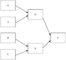
- 1-3 are schematic diagrams of a FlexE-based hierarchical network according to an embodiment of the present invention.
- 2-2 is a schematic diagram of data transmitted by a node in a related art to a first FlexE client
- 2-3 is a flowchart of mapping m first FlexE clients to a second FlexE client according to an embodiment of the present invention
- 2-4 are flowcharts for mapping data code blocks in data of each first FlexE client to designated time slots of a second FlexE client according to an embodiment of the present invention
- FIGS. 2-5 are schematic diagrams showing flow labels of a first FlexE client configured by a first node according to an embodiment of the present invention
- FIGS. 2-6 are schematic diagrams showing a data block flow of a second FlexE client according to an embodiment of the present invention.
- 2-7 are flowcharts of data for transmitting a second FlexE client according to an embodiment of the present invention.
- FIGS. 2-8 are schematic diagrams of data sent by a first node to a second FlexE client according to an embodiment of the present invention
- FIGS. 2-9 are schematic diagrams of another first node sending data of a second FlexE client according to an embodiment of the present invention.
- FIGS. 2-10 are schematic diagrams of still another data sent by a first node to a second FlexE client according to an embodiment of the present invention
- FIGS. 2-11 are schematic diagrams of still another data sent by a first node to a second FlexE client according to an embodiment of the present invention
- 3-1 is a flowchart of another data transmission method according to an embodiment of the present invention.
- 3-3 is a schematic structural diagram of a FlexE ring network with a faulty node according to an embodiment of the present invention
- 4-1 is a flowchart of still another data transmission method according to an embodiment of the present invention.
- 4-2 is a flowchart of performing a forwarding operation on data of a second FlexE client according to an embodiment of the present invention
- 5-1 is a schematic structural diagram of a data transmission apparatus according to an embodiment of the present invention.
- FIG. 5-2 is a schematic structural diagram of a mapping module according to an embodiment of the present disclosure.
- FIG. 5-3 is a schematic structural diagram of a mapping submodule according to an embodiment of the present disclosure.
- 6-1 is a schematic structural diagram of another data transmission apparatus according to an embodiment of the present invention.
- 6-2 is a schematic structural diagram of a first processing module according to an embodiment of the present invention.
- 6-3 is a schematic structural diagram of still another data transmission apparatus according to an embodiment of the present invention.
- 6-4 is a schematic structural diagram of still another first processing module according to an embodiment of the present invention.
- FIG. 7 is a schematic structural diagram of still another data transmission apparatus according to an embodiment of the present invention.
- a physical interface of a node with a K (1 ⁇ K ⁇ 254) time domain resource of 100 G can be bound to obtain one FlexE group, and one node can be configured with at least one FlexE group.
- the time domain resources of each of the K physical interfaces are divided into 20 5G time slots, and one FlexE group corresponds to 20*K time slots.
- 20*K time slots are divided into multiple groups, one set of time slots is used to transmit data of one FlexE client, and one FlexE client is a data stream.
- each group of time slots may include 1 time slot, may also include 2 time slots, and may also include 5 time slots and the like.
- a physical interface of the node P (that is, K is equal to 1) is bound to obtain a FlexE group.
- the group ID of the FlexE group is P1
- the FlexE group corresponds to 20 time slots
- the 20 time slots are divided into 2 groups, each group of slots includes 10 time slots.
- the first set of time slots is used to transmit the data of the FlexE client whose flow identifier is YL1
- the second set of time slots is used to transmit the data of the FlexE client whose flow identifier is YL2.
- the node P stores the correspondence between the node identifier, the group identifier of the FlexE group, the slot identifier, and the flow identifier of the FlexE client.
- the node identifier is used to uniquely identify the node
- the group identifier of the FlexE group is used for Uniquely identifies the FlexE group
- the FlexE customer's flow ID is used to uniquely identify the FlexE customer.
- the time slot identifier is used to uniquely indicate a time slot
- the time slot identifier may be the number of the time slot.
- the corresponding relationship can be as shown in Table 1. Referring to Table 1, the time slot with the slot identifiers 1 to 10 is used to transmit the data of the FlexE client whose flow identifier is YL1, and the time slot identifier is the time slot of 11 to 20. Used to transfer data from FlexE customers whose stream ID is YL2.
- FIG. 1-1 is a schematic diagram of an implementation environment involved in various embodiments of the present invention.
- the implementation environment may include a first node 001 and a second node 002.
- the first node 001 and the second node 002 are both devices supporting the FlexE technology.
- the first node and the second node may be switches or routers, and the like.
- the number of the first node and the second node is not limited in the embodiment of the present invention.
- the first node and the second node may be nodes in the FlexE ring network.
- the FlexE ring network may include multiple nodes, and multiple nodes form a working path WP and a protection path PP, and the working path. Both the WP and the protection path PP are paths that can be transmitted in both directions.
- the first node can be node A and the second node can be node D.
- Figures 1-2 exemplarily show two working paths WP, one protection path PP, the working path WP is indicated by a solid line, and the protection path PP is indicated by a broken line.
- protection switching is a very important link. Protection switching refers to the transmission of data through the protection path when the working path for transmitting data fails in the communication system. To avoid business disruptions.
- the ring network protection mode is often used to implement protection switching.
- the current ring network protection mode is only applicable to hierarchical network technologies, such as Multiprotocol Label Switching-Transport Profile (MPLS-). TP), Optical Transport Network (OTN), etc. Because FlexE customers and FlexE customers in FlexE technology do not have nesting relationship, FlexE technology is not a hierarchical network technology, but a flat structure network technology, so there is a need for a FlexE technology. Ring network protection.
- the present application when a node in the FlexE ring network detects that an element on the working path closest to the node (the element can be a node or a link) fails, the next step on the to-be-worked path can be The multiple working FlexE clients sent by the node are mapped to a protected FlexE client, and then the data of the protected FlexE client is transmitted along the protection path. Therefore, the present application provides a ring network protection method suitable for FlexE technology.
- the link between node A and node D has failed.
- the node A detects that the link between the node A and the node D on the working path WP is faulty, the node A can map the two working FlexE clients to be sent to the node D on the working path WP to one protection FlexE client. The data protecting the FlexE customer is then transmitted along the protection path PP to node D near the failed link.
- the first node and the second node may also be nodes in a FlexE-based hierarchical network.
- the FlexE-based hierarchical network may include multiple nodes, and multiple nodes are hierarchical structures.
- the first node may be the node G, the node A, the node B, and the node C of the first level
- the second node may be the node D and the node E of the second level.
- the Node B can map multiple first FlexE clients to one second FlexE client, and then transfer the data of the second FlexE client to the node E.
- Node C maps a plurality of first FlexE clients to a second FlexE client and then transmits the data of the second FlexE client to node E.
- the node E maps the two second FlexE clients to a third FlexE client, and then transmits the data of the third FlexE client to the node F.
- the node F can also map multiple third FlexEs and then transmit them. This multi-layered FlexE client mapping approach eliminates the need for nodes to process data at a FlexE client granularity.
- the application scenario of the first node and the second node is not limited in this embodiment of the present invention.
- Figure 2-1 is a flowchart of a data transmission method according to an embodiment of the present invention. The method may be applied to the implementation environment shown in Figure 1-1. As shown in Figure 2-1, the method may include:
- Step 201 The first node acquires m first FlexE clients, where m ⁇ 2.
- the first node may be a device supporting a FlexE technology such as a switch or a router.
- the first node In order to simultaneously transmit data of a plurality of first FlexE clients, the first node first acquires a plurality of first FlexE clients.
- a FlexE client is a data stream.
- Step 202 The first node maps the m first FlexE clients to a second FlexE client, wherein the time slot of each first FlexE client occupies the second FlexE client is fixed.
- the slots of the second FlexE client have a total of x (x ⁇ 2), and each slot in the x slots has a slot identifier.
- the time slot of each first FlexE client occupies the second FlexE client is fixed, that is, the time slot identifier of the time slot occupied by the data of each first FlexE client remains unchanged.
- the time slot identifiers of the five time slots are: ST1, ST2, ST3, ST4 and ST5, respectively.
- the first node acquires two first FlexE clients: the first FlexE client.
- the data of the first FlexE client YL1 occupies the time slot identifier of the second FlexE client as ST1 and ST2
- the gap that is, the data of the first FlexE client YL1 occupies the first two slots of the second FlexE client; the data of the first FlexE client YL2 occupies the slot of the second FlexE client identified as the slots of ST3, ST4 and ST5 That is, the data of the first FlexE client YL2 occupies the last three slots of the second FlexE client.
- the data of the first FlexE client YL1 is always occupied by the time slot identifiers ST1 and ST2, and the data of the first FlexE client YL2 is always occupied by the time slot identifiers ST3, ST4 and ST5.
- the data of the first FlexE client YL1 and the data of the first FlexE client YL2 occupy the second FlexE client's time slot unchanged, facilitating data recovery.
- the clock corresponds to the data transmission rate.
- the node L1, the node L2, and the node L3 are sequentially connected, and the data transmission rate of the node L2 is 10 Gbps (gigabits per second), and the data transmission rate of the node L1 may be (10 Gbps + 100 ppm), and the data transmission rate of the node L3. May be (10Gbps-100ppm).
- the node L1 sends the data of the first FlexE client to the node L3 through the node L2, since the data transmission rate of the node L1 is greater than the data transmission rate of the node L2 and the data transmission rate of the node L3, in order to ensure that the node L2 can
- the data to be sent is sent to the node L3 in time to prevent more data from being sent out on the node L2, and the node L2 needs to perform a rate adjustment operation. For example, when performing a rate adjustment operation, the node L2 may delete some redundant idle (IDLE) code blocks in the data to increase the rate of data transmission.
- IDLE redundant idle
- the node L2 when the data transmission rate of the node L1 is (10G bps - 100ppm) and the data transmission rate of the node L3 is (10G bps + 100ppm), in order to ensure normal data transmission, the node L2 also needs to perform rate adjustment operations, for example, Node L2 may add some idle code blocks in the data of the first FlexE client currently to be transmitted to reduce the rate of data transmission.
- this operation of idle code block addition or idle code block deletion for adjusting the rate increases the uncertainty of the time slot occupied by the first FlexE client's data during transmission, that is, the first FlexE client.
- the data blocks in the data will appear on different time slots in different time periods, which increases the difficulty of data recovery.
- the data transmission rate of the node L1 is smaller than the data transmission rate of the node L2
- the data transmission rate of the node L2 is smaller than the data transmission rate of the node L3
- the data of the first FlexE client YL1 includes six data code blocks: K1, K2, K3, K4, K5 and K6.
- the node L1 When the node L1 sends the data of the first FlexE client YL1 to the node L2, since the data transmission rate of the node L1 is smaller than the data transmission rate of the node L2, the node L1 may add two idle code blocks in the six data code blocks, the first The idle code blocks are located between K2 and K3, and the second idle code block is located after K6.
- the data of the first FlexE client YL1 processed on the node L1 is sent to the node L2 through 2 time slots, wherein K1, the first idle code block, K4 and K6 occupy 1 time slot, K2, K3, K5 and The second idle code block occupies 1 time slot.
- node L2 When the node L2 receives the data of the processed first FlexE client YL1, first deletes two idle code blocks in the data, and then, when transmitting six data code blocks to the node L3, the data transmission rate of the node L2 is smaller than the node. L3 data transmission rate, node L2 can add 2 idle code blocks in 6 data code blocks, the first idle code block is located between K3 and K4, and the second idle code block is located after K6, and is processed on node L2.
- the data of the first FlexE client YL1 is transmitted through 2 time slots, wherein K1, K3, K4 and K6 occupy 1 time slot, K2, the first idle code block, K5 and the second idle code block occupy 1 time slot.
- both the node L1 and the node L2 perform an idle code block adding operation on the data of the first FlexE client YL1, and the positions of the added idle code blocks are different, and the data code blocks in the data of the first FlexE client YL1 are The time slots occupied during transmission have changed.
- the node when transmitting the data of the plurality of first FlexE clients, maps the plurality of first FlexE clients to one second FlexE client, and the data of each first FlexE client occupies the second FlexE client.
- the time slot is fixed, that is, the time slot of the second FlexE client occupied by the data of each first FlexE client during the transmission remains unchanged, thus facilitating data recovery.
- step 202 may include:
- Step 2021 The first node deletes q idle code blocks in the data of the p first FlexE clients, where 1 ⁇ p ⁇ m, q ⁇ 1.
- the first node may pre-pse data of p(1 ⁇ p ⁇ m) first FlexE clients before mapping m first FlexE clients to one second FlexE client. Processing, for example, may delete some redundant idle code blocks in the data of the p first FlexE clients, so as to be able to continuously add multiple idle code blocks in the data code block stream of the second FlexE client, and continuously add the A plurality of idle code blocks are used to ensure that the data of the first FlexE client occupies the time slot of the second FlexE client is fixed.
- the first node When the first node deletes the idle code blocks in the data of the p first FlexE clients, it deletes the q idle code blocks in the data of each of the first FlexE clients respectively. Assuming that m is equal to 5, p is equal to 2, q is equal to 1, then the first node can delete the spatial code blocks in the data of the two first FlexE clients, and delete one idle code block for each data of the first FlexE client. .
- Step 2021 is an optional step.
- the first node may not perform step 2021.
- Step 2022 The first node maps the data code block in the data of each of the first FlexE clients of the m first FlexE clients to the designated time slot of the second FlexE client, to obtain the data code block stream of the second FlexE client. .
- the first node maps the data code block in the data of each of the first FlexE clients of the m first FlexE clients to the designated time of the second FlexE client.
- the gap it can include:
- Step 2022a The first node sorts the m first FlexE clients according to a preset sorting manner.
- the m first FlexE clients may be sorted, and then each of the first The data code blocks in the data of a FlexE client are mapped into designated time slots of the second FlexE client.
- the step 2022a may include: sorting the m first FlexE clients according to the content of the flow label corresponding to each of the first FlexE clients of the m first FlexE clients.
- the first FlexE client can be identified by the flow label corresponding to the first FlexE client.
- the first node is configured with a flow label corresponding to the first FlexE client.
- the flow label corresponding to the first FlexE client can be used to indicate the forwarding path of the data of the first FlexE client.
- the information included in the flow label of the first FlexE client can be represented by multiple representations.
- the following methods are used as an example.
- the flow label of the first FlexE client configured at the first node may include: a node identifier of all nodes for transmitting data of the first FlexE client, for transmitting data of the first FlexE client. Relationship information of any two adjacent nodes.
- the relationship information of the adjacent two nodes may include: the first FlexE client is used for The group ID of the FlexE group to which the node of the data of the first FlexE client is sent, the stream identifier of the first FlexE client, and the information of the time slot occupied by the data of the first FlexE client.
- the flow identifiers of the first FlexE clients configured for different neighboring nodes are different.
- the flow identifier of a certain first FlexE client configured on the first node is YL111
- the flow identifier of the first FlexE client configured on the third node is YL222.
- the node identifier may be a Media Access Control (MAC) address or an Internet Protocol (IP) address of the node.
- MAC Media Access Control
- IP Internet Protocol
- each node may also be assigned a node number, and the node identifier may also be the node number of the corresponding node.
- the information of the time slot may be the time slot identifier of the time slot occupied by the data of the first FlexE client.
- the time slot identifier may be the number of the time slot, or may be information for indicating the location of the time slot, etc.
- the position of the gap can be expressed in the form of a bitmap file.
- a certain first FlexE client is transmitted from the first node 001 to the second node 002 through the third node 003, and the flow identifier of the first FlexE client configured on the first node 001 is configured.
- the flow identifier of the first FlexE client configured on the third node is YL222
- the flow identifier of the first FlexE client configured on the second node is YL333.
- the first node 001 is configured with two FlexE groups, and the group ID of the FlexE group to which the first FlexE client belongs is GP1, and the time slot of the time slot occupied by the first FlexE client between the first node 001 and the third node 003
- the identifiers are 1, 2 and 3.
- the third node 003 is configured with two FlexE groups, the group ID of the FlexE group to which the first FlexE client belongs is GP3, and the time slot of the time slot occupied by the first FlexE client between the third node 003 and the second node 002
- the logos are 7, 8, and 9.
- the flow label of the first FlexE client configured in the first node 001 may include: a node identifier 001 of the first node 001, a node identifier 003 of the third node 003, and a node identifier 002 of the second node 002, the first node 001 Relationship information with the third node 003: the group identifier GP1 of the FlexE group to which the first FlexE client belongs, the stream identifier YL111 of the first FlexE client, and the slot identifier 1 of the slot occupied by the data of the first FlexE client , 2 and 3, relationship information of the third node 003 and the second node 002: the group identifier GP3 of the FlexE group to which the first FlexE client belongs, the stream identifier YL222 of the first FlexE client, and the data of the first FlexE client
- the time slot identifiers of the occupied time slots are 7, 8, and 9.
- the flow label of the first FlexE client configured at the first node may include: an inflow node of the first FlexE client, the first An outbound node of the FlexE client, used to transmit relationship information of any two adjacent nodes of the data of the first FlexE client.
- the flow identifiers of the first FlexE clients configured by different nodes may be the same.
- the flow identifier of a certain first FlexE client configured on the first node is YL111
- the first FlexE configured on the third node is still YL111.
- the flow label of the first FlexE client configured at the first node may include: an inflow node of the first FlexE client, the first FlexE client The outbound node, the flow identifier of the first FlexE client, and the group identifier of the FlexE group to which the first FlexE client belongs in the node for transmitting the data of the first FlexE client in any two adjacent nodes.
- the flow label of the first FlexE client includes the group identifier of the FlexE group to which the first FlexE client belongs and the first
- information about the time slot occupied by the data of the first FlexE client may be obtained based on the group identifier of the FlexE group to which the first FlexE client belongs and the flow identifier of the first FlexE client.
- the flow label of the first FlexE client may not include the information of the time slot occupied by the data of the first FlexE client.
- the flow label of the first FlexE client may include: an inflow node of the first FlexE client, an outflow node of the first FlexE client, and a flow identifier of the first FlexE client.
- the flow identifier of the first FlexE client configured by different nodes is the same.
- the m first FlexE clients are sorted according to the content of the flow label corresponding to each of the first FlexE clients, for example, may be based on the first The representation of the content of the stream tag corresponding to the FlexE client, sorting the m first FlexE clients.
- the first node may follow the string included in the flow label corresponding to each of the first FlexE clients of the m first FlexE clients. Size, sorting m first FlexE clients, usually comparing the size of the string based on the ASCII value of the corresponding character of the string.
- the flow label corresponding to the first FlexE client YL1 is bdcedfs
- the flow label corresponding to the first FlexE client YL2 is abckjhnd
- each character of the two strings is compared from left to right, due to the number of bdcedfs
- abckjhnd first bit is a
- b ASCII code value is greater than a ASCII code value
- bdcedfs is greater than abckjhnd
- the first node may be the size of the binary number included in the flow label corresponding to each of the first FlexE clients of the m first FlexE clients. , sorting m first FlexE customers. Assuming that m is equal to 2, the flow label corresponding to the first FlexE client YL1 is 010111, and the flow label corresponding to the first FlexE client YL2 is 101010, since the number of digits of 010111 is the same as the number of digits of 101010, and is compared from left to right, 010111 The first bit is 0,101010, the first bit is 1, so 0101110 is less than 101010. Therefore, the sorting result of the first node sorting the first FlexE client YL1 and the first FlexE client YL2 is the first FlexE client YL2 is the first One, the first FlexE customer YL1 is the second.
- Step 2022b The first node maps the data code blocks in the data of each of the first FlexE clients of the m first FlexE clients to the designated time slots of the second FlexE client according to the sorting order.
- the data code blocks in the data of each first FlexE client are mapped to the designated time slots of the second FlexE client in a sorting order, which improves the mapping efficiency of the data code blocks.
- the first node follows the string contained in the flow label corresponding to each of the first FlexE clients of the two first FlexE clients (including the first FlexE client YL1 and the first FlexE client YL2).
- the size of the two first FlexE customers is sorted.
- the sorted result is the first FlexE customer YL1 for the first place, and the first FlexE customer YL2 for the second place.
- the slot identifiers of the 5 slots are: ST1, ST2, ST3, ST4, and ST5, respectively, then in step 2022b, the first node will be the first FlexE client YL1.
- the data blocks in the data are mapped to the time slots of the second FlexE client identified as the time slots of ST1 and ST2, and the data blocks in the data of the first FlexE client YL2 are mapped to the time slots of the second FlexE client identified as ST3, ST4 and The time slot of ST5, that is, the data of the first FlexE client YL1 occupies the first two time slots of the second FlexE client, and the data of the first FlexE client YL2 occupies the last three time slots of the second FlexE client.
- Step 2023 The first node continuously adds N idle code blocks in the data code block stream of the second FlexE client, where N is an integer multiple of the number of time slots of the second FlexE client.
- the N idle code blocks may be continuously added at any position in the data code block stream of the second FlexE client.
- the location of the N idle code blocks is not limited in the embodiment of the present invention.
- the data code blocks in the data of the first FlexE client YL1 are K1, K2, K3 and K4, and the first node will be in the data of the first FlexE client YL1.
- the data code block is mapped to the first two time slots of the second FlexE client, where K1 and K3 are mapped to the first time slot of the second FlexE client, and K2 and K4 are mapped to the second time of the second FlexE client
- the data blocks in the data of the first FlexE client YL2 are K5, K6, K7, K8, K9 and K10, and the first node maps the data code blocks in the data of the first FlexE client YL2 to the second FlexE client.
- N is an integer multiple of 5
- idle code blocks may be added consecutively between K1 and K2, which is not limited in this embodiment of the present invention.
- Step 203 The first node transmits data of the second FlexE client to the second node.
- the second node is different from the first node.
- first node and the second node may be nodes in a FlexE ring network, and the first node and the second node may also be nodes in a FlexE-based hierarchical network.
- step 203 may include:
- Step 2031 The first node sends data of the second FlexE client to the third node.
- the third node is a node between the first node and the second node when transmitting data of the second FlexE client.
- the first node continuously adds 5 idle code blocks between K1 and K2, and the schematic diagram of the first node sending the data of the second FlexE client to the third node is shown in FIG. 2
- the first node transmits the data of the second FlexE client to the third node according to the time slot in which the data code block in the data of each first FlexE client is mapped.
- the first node transmits K1 and K3 in the data of the first FlexE client YL1 through the first time slot of the second FlexE client, and transmits K2 in the data of the first FlexE client YL1 through the second time slot of the second FlexE client.
- K4 the K5 and K8 in the data of the first FlexE client YL2 are transmitted through the third time slot of the second FlexE client.
- the first node continuously adds five idle code blocks between K2 and K3, and the data transmission diagram of the second FlexE client is as shown in FIG. 2-9, and the first node passes the first
- the first time slot of the second FlexE client transmits K1 and K3 in the data of the first FlexE client YL1, and transmits the K2 and K4 in the data of the first FlexE client YL1 through the second time slot of the second FlexE client.
- the third time slot of the second FlexE client transmits K5 and K8 in the data of the first FlexE client YL2.
- the first node continuously adds 10 idle code blocks between K5 and K6, and the data transmission diagram of the second FlexE client is as shown in FIG. 2-10, and the first node passes the first
- the first time slot of the second FlexE client transmits K1 and K3 in the data of the first FlexE client YL1, and transmits the K2 and K4 in the data of the first FlexE client YL1 through the second time slot of the second FlexE client.
- the third time slot of the second FlexE client transmits K5 and K8 in the data of the first FlexE client YL2.
- the first node continuously adds five idle code blocks between K7 and K8, and the data transmission diagram of the second FlexE client is as shown in FIG. 2-11, and the first node passes the first
- the first time slot of the second FlexE client transmits K1 and K3 in the data of the first FlexE client YL1, and transmits the K2 and K4 in the data of the first FlexE client YL1 through the second time slot of the second FlexE client.
- the third time slot of the second FlexE client transmits K5 and K8 in the data of the first FlexE client YL2.
- the data of each first FlexE client can be occupied regardless of which position in the data block stream of the second FlexE client is continuously added to the N idle code blocks.
- the time slot of the second FlexE client is fixed.
- N is an integer multiple of the number of slots of the second FlexE client, so the first node is
- (N/l) idle code blocks can exist in each time slot of the second FlexE client time slot, where l is the time slot of the second FlexE client. Number.
- the data of the first FlexE client YL1 is always the first two time slots of the second FlexE client, and the data of the first FlexE client YL2 is always occupied by the last three times of the second FlexE client. Gap.
- Step 2032 When the third node continuously detects N idle code blocks in the data code block stream of the second FlexE client, deleting N idle code blocks.
- the third node when the third node detects that there are five idle code blocks continuously in the data code block stream of the second FlexE client, the five idle code blocks are deleted, so that the third node is in the direction.
- the rate adjustment operation is performed when the next node sends data of the second FlexE client.
- Step 2033 The third node continuously adds N idle code blocks in the processed data stream of the second FlexE client when transmitting the processed data of the second FlexE client to the second node.
- the third node performs an idle code block adding operation on the data of the second FlexE client after deleting the N idle code blocks at the exit: the data of the processed second FlexE client.
- N idle code blocks are continuously added to the code stream, and N is an integer multiple of the number of slots of the second FlexE client.
- the idle code block adding operation performed by the third node is the same as the idle code block adding operation performed by the first node, and the process may refer to step 2023, and details are not described herein again.
- the data of the second FlexE client added with the idle code block is sent to the second node.
- FIG. 2-8 exemplarily shows There is a third node between the first node and the second node.
- the number of the third node is not limited in the embodiment of the present invention.
- the third node can also add or delete a small number of idle code blocks according to actual needs.
- Step 204 The second node performs a forwarding operation or a recovery operation on the data of the second FlexE client.
- the second node When the first node and the second node are nodes in the FlexE ring network, the second node performs a recovery operation on the data of the second FlexE client; when the first node and the second node are nodes in the FlexE-based hierarchical network The second node performs a forwarding operation on the data of the second FlexE client.
- the data transmission method provided by the embodiment of the present invention, because the first node can map the acquired multiple FlexE clients to one second FlexE client, and transmit the data of the second FlexE client to the second node.
- the second node is different from the first node.
- the data of each first FlexE client occupies the second FlexE client's time slot is fixed, so that the node does not need to process data with a FlexE client granularity, which reduces the need for the node to process.
- the sheer number of fine-grained FlexE customers reduces the performance requirements for processing data at the node.
- FIG. 3-1 is a flowchart of a data transmission method according to an embodiment of the present invention. The method may be applied to the implementation environment shown in Figure 1-2. The method may include:
- Step 301 When detecting that a component closest to the first node in the working path fails, the first node acquires m working FlexE clients to be sent to the next node on the working path, where m ⁇ 2.
- This element is a node or link.
- the first node may detect, according to the pre-configured fault detection protocol, whether an element closest to the first node on the working path is faulty.
- the fault detection protocol can be a fault detection protocol used in network technologies such as OTN, Ethernet or MPLS.
- the first node may perform a protection coordination operation based on the pre-configured protection switching protocol to coordinate the related nodes to complete the protection switching process.
- the protection switching protocol may be an Automatic Protection Switching (APS) protocol.
- APS Automatic Protection Switching
- the process of fault detection and protection coordination can refer to related technologies.
- the first node is the node A
- the second node is the node D.
- the link between the node A and the node D is faulty as an example.
- Each node in Figure 1-2 can be configured with ring network information of the FlexE ring network.
- the ring network information can include the number of nodes, the node identifier of each node, the connection relationship between the nodes, and the transmission direction of the working FlexE client. Inflow and outbound nodes, fault detection protocols, and protection switching protocols for each working FlexE client.
- the node identifier may be a MAC address or an IP address of the node.
- each node may be assigned a node number, and the node identifier may also be a node number of the node.
- the embodiment of the present invention does not limit the form of the node identifier of the node.
- the ring network information may also include the flow identifier of the working FlexE client to be protected.
- the flow ID of the working FlexE client can be represented by 16-bit data.
- the working ID of the working FlexE client can be 0111000011110001.
- the highest bit of the 16-bit data can also be used to indicate whether the FlexE customer is a working FlexE customer. For example, when the highest bit is 0, the FlexE customer is a working FlexE customer.
- the working path WP in Figure 1-2 is used to transfer data for two working FlexE customers: working FlexE customer YL1 and working FlexE customer YL2.
- the inflow node of the working FlexE client YL1 is node A, and the outbound node is node D.
- the inflow node of the working FlexE client YL2 is node A, and the outbound node is node C.
- node A When node A detects that the link between node A and node D is faulty, node A sends the fault information to node B, node C, and node D to complete the protection coordination process, and node A acquires the to-be-worked path. Node D sends the working FlexE client YL1 and the working FlexE client YL2.
- Step 302 The first node maps the m working FlexE clients to a protection FlexE client, wherein the data occupation of each working FlexE client occupies a fixed time slot of the FlexE client.
- FIG. 1-2 it is assumed that there are five slots for protecting FlexE clients.
- the slot identifiers of the five slots are: ST1, ST2, ST3, ST4, and ST5.
- Node A obtains the working FlexE customer YL1 and the working FlexE customer YL2.
- the working data of the FlexE customer YL1 occupies the first two time slots of the FlexE customer; working FlexE customers
- the data of YL2 occupies the last three slots of the FlexE customer.
- the data of the working FlexE client YL1 is always occupied by the time slot identifiers ST1 and ST2, and the data of the working FlexE client YL2 is always occupied by the time slot identifiers ST3, ST4 and ST5.
- Working with FlexE customer YL1 data and working with FlexE customer YL2 data occupancy protection FlexE customer time slots remain unchanged.
- the node needs to perform rate adjustment operations, such as reducing the rate of data transmission by adding some idle code blocks, and increasing by deleting some idle code blocks.
- rate adjustment operations such as reducing the rate of data transmission by adding some idle code blocks, and increasing by deleting some idle code blocks.
- the rate of data transmission however, the operation of idle code block addition or idle code block deletion increases the uncertainty of the time slot used to protect the FlexE client's data during transmission, thereby increasing the difficulty of data recovery.
- the time slot of each working FlexE client occupies the protection of the FlexE client is fixed, that is, the time slot of the protection FlexE client occupied by the data of each working FlexE client remains unchanged during the transmission process. In this way, it is convenient for data recovery.
- step 302 may include:
- the first node deletes q idle code blocks in the data of the p working FlexE clients, 1 ⁇ p ⁇ m, q ⁇ 1.
- node A in order to meet the data transmission rate requirements between nodes, node A can delete p (1 ⁇ p ⁇ 2) working FlexE clients before mapping two working FlexE clients. Some redundant idle code blocks in the data, so that multiple idle code blocks can be continuously added in the data code block stream of the protection FlexE client, and the plurality of idle code blocks continuously added are used to ensure the data occupation of the working FlexE client.
- the time slot for protecting FlexE customers is fixed.
- the first node may not perform this step.
- the first node maps the data code blocks in the data of each working FlexE client of the m working FlexE clients to the designated time slot of the protection FlexE client to obtain a data code block stream for protecting the FlexE client.
- the node A may sort the working FlexE client YL1 and the working FlexE client YL2 according to a preset sorting manner, for example, according to the content of the flow label corresponding to each working FlexE client.
- the flow label corresponding to the working FlexE client is used to indicate the forwarding path of the data of the working FlexE client.
- node A Based on the sorting order, node A sequentially maps the data code blocks in the data of the two working FlexE clients to the designated time slots of the protection FlexE client. Assume that there are 5 time slots for protecting FlexE customers.
- Node A maps the working FlexE client YL1 to the first two time slots of the protection FlexE client based on the sorting order, and maps the working FlexE client YL2 to the last three time slots of the protection FlexE client. in.
- the nodes used to transmit the data of the working FlexE client are configured with the flow label corresponding to the working FlexE client.
- the node A and the node D are configured with a flow label corresponding to the working FlexE client YL1
- the node A, the node D, and the node C are configured with a flow label corresponding to the working FlexE client YL2.
- the flow label corresponding to the work FlexE client YL1 may include: the inflow node of the working FlexE client YL1, that is, the node A, the outflow node of the working FlexE client YL1, that is, the node D, and the flow identifier of the working FlexE client YL1, that is, the YL1.
- the working ID of the working FlexE client YL1 configured by node A and node D is the same, both are YL1.
- the flow label corresponding to the working FlexE client YL2 may include: the inflow node of the working FlexE client YL2, that is, the node A, the outflow node of the working FlexE client YL2, that is, the node C, and the flow identifier of the working FlexE client YL2, that is, the YL2.
- the working FlexE client YL2 configured by node A, node D, and node C has the same flow identifier, and is YL2.
- the process of this step can refer to step 2022.
- the first node continuously adds N idle code blocks in the data code block stream of the protection FlexE client, where N is an integer multiple of the number of slots protecting the FlexE client.
- Node A maps the data blocks in the data of FlexE client YL1 to the first two slots protecting the FlexE client.
- Node A The data code blocks in the data of the working FlexE client YL2 are mapped to the last three time slots of the second FlexE client.
- node A continuously adds N idle code blocks in the data block stream of the protection FlexE client, it can continuously add 5, 10 or 15 idle code blocks in the data code block stream protecting the FlexE client.
- the process of this step can refer to step 2023.
- Step 303 The first node transmits the data of the protection FlexE client to the second node along the protection path.
- the second node is a node that is close to the failed element.
- the first node when the first node detects that the element closest to the first node on the working path in the FlexE ring network fails, the first node can send the next node to the working path to the m.
- the working FlexE customers are mapped to a FlexE customer, and the data footprint of each working FlexE customer is fixed to protect the FlexE customer's time slot.
- the first node transmits data protecting the FlexE client to the second node along a protection path in the FlexE ring network, and the second node is a node close to the failed element, which reduces performance requirements for processing data of the node, It also avoids the interruption of the service when the working path fails. Therefore, the reliability of data transmission is improved, and a reliable ring network protection method is provided for the FlexE technology.
- Step 303 can include the first node transmitting data of the second FlexE client to the third node along the protection path.
- the third node deletes N idle code blocks when it detects that there are N idle code blocks consecutively in the data code block stream of the second FlexE client. Then, when the third node transmits the processed data of the second FlexE client to the second node, N idle code blocks are continuously added in the processed data stream of the second FlexE client.
- node A when node A detects that the link between node A and node D is faulty, node A performs a protection coordination operation based on the pre-configured protection switching protocol: node A sends the failure information. To Node B, Node C, and Node D.
- the node A when transmitting the data protecting the FlexE client, the node A first sends the data protecting the FlexE client to the node B according to the time slot in which the data code block in the data of the working FlexE client YL1 and the working FlexE client YL2 is mapped, and the node B When it is detected that there are N idle code blocks continuously in the data code block stream protecting the FlexE client, N idle code blocks are deleted, so that the Node B performs a rate adjustment operation when transmitting data for protecting the FlexE client to the node C.
- the Node B performs an idle code block adding operation on the data of the protected FlexE client after the N idle code blocks are deleted at the egress: continuously adding N idle code blocks in the processed data stream of the protected FlexE client, N An integer multiple of the number of slots for the FlexE client.
- the idle code block addition operation performed by the Node B is the same as the idle code block addition operation performed by the Node A.
- the data of the protected FlexE client added with the idle code block is sent to the node C, and the node C sends the data of the protected FlexE client added with the idle code block according to the processing mode of the node B. To node D.
- Node B and Node C can add or delete a small number of idle code blocks according to actual needs.
- the process of this step can refer to step 2031 to step 2033.
- Step 304 The second node restores the FlexE client to m working FlexE clients.
- step 304 may include:
- Step 3041 When it is detected that there are N idle code blocks consecutively in the data code block stream of the second FlexE client, the second node deletes N idle code blocks.
- rate matching is completed, and the third node deletes 5 idle code blocks in the data block stream of the second FlexE client at the ingress.
- 5 idle code blocks after which 5 idle code blocks are continuously added in the processed data stream of the second FlexE client, and the second node continuously has 5 idle codes in the data stream of the second FlexE client.
- the block is deleted, the 5 free code blocks are deleted.
- Step 3042 The second node recovers m first FlexE clients according to the location of the data code block in the data of each first FlexE client.
- the second node recovers the first FlexE according to the location of the data code block in the data of the first FlexE client YL1 and the location of the data code block in the data of the first FlexE client YL2.
- Customer YL1 and first FlexE customer YL2 wherein the data code blocks in the data of the first FlexE client YL1 are K1, K2, K3 and K4, and the data code blocks in the data of the first FlexE client YL2 are K5, K6, K7 , K8, K9 and K10.
- the node D when the node D detects that there are N idle code blocks continuously in the data code block stream of the protection FlexE client sent by the node C, the N idle code blocks are deleted. After that, the node D restores the two working FlexE clients according to the position of the data code block in the data of the working FlexE client YL1 and the working FlexE client YL2.
- Step 305 The second node performs a target operation on data of each working FlexE client of the m working FlexE clients.
- the target operation is a forward operation or a drop operation.
- step 305 can include:
- the discard operation is performed on the data of the working FlexE client
- the forwarding operation is performed on the data of the working FlexE client.
- the flow label corresponding to the working FlexE client is used to indicate the forwarding path of the data of the working FlexE client.
- Node D detects that the node is configured with the flow label corresponding to the working FlexE client YL1, then the node D can determine the working FlexE based on the flow label corresponding to the working FlexE client YL1.
- the data of the client YL1 passes through the node D, and therefore, the node D performs a forwarding operation on the data of the working FlexE client YL1.
- Node D detects that the node is configured with the flow label corresponding to the working FlexE client YL2, then the node D can determine that the data of the working FlexE client YL2 passes through the node D based on the flow label corresponding to the working FlexE client YL2, and is working.
- the next node of node D on the path is node C. Therefore, node D performs a forwarding operation on the data of the working FlexE client YL2.
- the working path WP is used to transmit data of three working FlexE customers. : Working FlexE customer YL1, working FlexE customer YL2 and working FlexE customer YL3.
- the inflow node of the working FlexE client YL1 is node A, and the outbound node is node D.
- the inflow node of the working FlexE client YL2 is node A, and the outbound node is node C.
- the inflow node of the working FlexE client YL3 is node D, and the outbound node is node C.
- Node A and node D are configured with flow labels corresponding to working FlexE client YL1
- node A, node D and node C are configured with flow labels corresponding to working FlexE client YL2
- node D and node C are configured with flow labels corresponding to working FlexE client YL3.
- the flow label corresponding to the working FlexE client YL1 may include: the inflow node of the working FlexE client YL1, that is, the node A, the outflow node of the working FlexE client YL1, that is, the node D, and the flow identifier of the working FlexE client YL1, that is, the YL1.
- the working ID of the working FlexE client YL1 configured by node A and node D is the same, both are YL1.
- the flow label corresponding to the working FlexE client YL2 may include: the inflow node of the working FlexE client YL2, that is, the node A, the outflow node of the working FlexE client YL2, that is, the node C, and the flow identifier of the working FlexE client YL2, that is, the YL2.
- the working FlexE client YL2 configured by node A, node D, and node C has the same flow identifier, and is YL2.
- the flow label corresponding to the working FlexE client YL3 may include: the inflow node of the working FlexE client YL3, that is, the node D, the outflow node of the working FlexE client YL3, that is, the node C, and the flow identifier of the working FlexE client YL3, that is, the YL3.
- the working ID of the working FlexE client YL3 configured by node D and node C is the same, both of which are YL3.
- node A When node A detects that node D is faulty, node A sends fault information to node B and node C to complete the protection coordination process. At the same time, since the inflow node of working FlexE client YL3 is node D, node A only obtains the pending work. Node D on the path sends the working FlexE client YL1 and the working FlexE client YL2. Node A maps the working FlexE client YL1 and the working FlexE client YL2 to a protected FlexE client, working with the FlexE client YL1 data and working with the FlexE client YL2. The data footprint of the FlexE client is fixed. Node A then transmits the data protecting the FlexE client to node C along the protection path PP. After that, Node C will protect the FlexE customer from 2 working FlexE customers: working FlexE customer YL1 and working FlexE customer YL2.
- Node C detects that the node is not configured with the flow label corresponding to the working FlexE client YL1, then the node C can determine that the data of the working FlexE client YL1 does not pass through the node C, therefore, the node C works for the FlexE client YL1.
- the data performs a discard operation.
- Node C detects that the node is configured with the flow label corresponding to the working FlexE client YL2, then the node C can determine that the data of the working FlexE client YL2 passes through the node C based on the flow label corresponding to the working FlexE client YL2, therefore, the node C performs a discard operation on the data of the working FlexE client YL2.
- the node D can directly transmit the data containing the error code block or the idle code block.
- the data transmission method can detect the next element on the working path in the FlexE ring network when the element closest to the first node fails.
- the m(m ⁇ 2) working FlexE clients sent by one node are mapped to one protection FlexE client, and the data occupation of each working FlexE client is fixed.
- the time slot of the FlexE client is fixed.
- the first node is along the FlexE ring network.
- the protection path will protect the data of the FlexE client to the second node, and the second node is the node close to the failed element.
- the method does not need to map the multiple FlexE clients to a second FlexE client.
- a FlexE client processes data for granularity, reduces the performance requirements for processing data at the node, and avoids business interruption when the working path fails. Therefore, the reliability of data transmission is improved, providing a reliable FlexE technology. Ring protection.
- Figure 4-1 is a flowchart of a data transmission method according to an embodiment of the present invention. The method may be applied to the implementation environment shown in Figure 1-3. The method may include:
- Step 401 The first node acquires m first FlexE clients, where m ⁇ 2.
- the first node may be a Node B of the first level in the FlexE-based hierarchical network
- the second node is the node E of the second level.
- Step 402 The first node maps the m first FlexE clients to a second FlexE client, wherein the time slot of each of the first FlexE clients occupies the second FlexE client is fixed.
- the first node may sort the m first FlexE clients according to the content of the flow label corresponding to each of the first FlexE clients, and then sort the m first FlexEs according to the sorting order.
- the data code blocks in the data of each of the first FlexE customers in the customer are mapped into designated time slots of the second FlexE client.
- each node may perform a recovery operation on the data.
- the node performing the mapping operation and the node performing the recovery operation are known, and the data transmission can be completed when the node performing the mapping operation and the node performing the recovery operation are configured with the flow label corresponding to the first FlexE client. Therefore, the representation of the information included in the flow label corresponding to the first FlexE client may be more simplified.
- the flow label corresponding to the first FlexE client may include: the flow identifier of the first FlexE client and the data of the first FlexE client. size. The flow ID of the first FlexE client configured by different nodes is the same.
- Node B acquires three first FlexE clients, and Node B maps the three first FlexE clients to one second FlexE client ZL1.
- step 402 can refer to step 202.
- the first node may perform multiple mapping operations, that is, step 402 may include: the first node performs multiple mapping operations on the m first FlexE clients, to perform m A FlexE customer is mapped to a second FlexE customer.
- the first node may perform multiple mapping operations on the m first FlexE clients based on the first packet remapping.
- the process is described by taking the mapping operation performed by the first node as an example. First, the first node divides the m first FlexE clients into L (L ⁇ 2) groups, and at least one of the L groups includes at least 2 The first FlexE customer.
- the first node maps the first FlexE client included in each group in the L group to one target FlexE client (the data of the first FlexE client in each group occupies a fixed time slot of the target FlexE client is fixed), and obtains L Target FlexE customers. This completes the first mapping operation. Thereafter, the first node maps the L target FlexE clients to a second FelxE client (the data of each target FlexE client occupies the second FelxE client's time slot is fixed), and the second mapping operation is completed.
- Step 403 The first node transmits data of the second FlexE client to the second node.
- the second node is different from the first node.
- Node B maps the three first FlexE clients to one second FlexE client ZL1, and then Node B transmits the data of the second FlexE client ZL1 to Node E.
- step 403 can refer to step 203.
- Step 404 The second node performs a forwarding operation on the data of the second FlexE client.
- step 404 can include:
- Step 4041 The second node maps the second FlexE client and another second FlexE client transmitted by another node to the third FlexE client.
- Another second FlexE client is obtained by mapping the obtained first FlexE clients by another node, wherein the data of the second FlexE client and the data of the second FlexE client occupy the time slot of the third FlexE client. It is fixed for data recovery.
- the node B transmits the data of the second FlexE client ZL1 to the node E, and the node E maps the second FlexE client ZL1 and the second FlexE client ZL2 transmitted by the received node C to the first Three FlexE customers.
- the second FlexE client ZL2 is obtained by mapping the two first FlexE clients obtained by the node C.
- the time slots of the second FlexE client ZL1 and the second FlexE client ZL2 occupying the third FlexE client are fixed.
- step 4041 can refer to step 202.
- Step 4042 The second node transmits data of the third FlexE client to the next node.
- the node E transmits the data of the third FlexE client obtained in step 4041 to the node F.
- the node F can also map multiple third FlexEs according to the same mapping manner, and then transmit.
- the next node may be based on the data of the second FlexE client.
- the size and the second FlexE customer are mapped to the order of the third FlexE customer, recovering multiple second FlexE customers.
- the next node may obtain the size of the data of the second FlexE client based on the flow label corresponding to the first FlexE client configured in the node.
- the flow label corresponding to the first FlexE client includes: the flow identifier of the first FlexE client and the size of the data of the first FlexE client.
- the node B transmits the data of the second FlexE client ZL1 to the node E, and the node E maps the second FlexE client ZL1 and the second FlexE client ZL2 transmitted by the received node C to the third FlexE.
- the customer then transmits the data of the third FlexE client to node F.
- the node F may be based on the size of the data of the second FlexE client ZL1, the order in which the second FlexE client ZL1 is mapped to the third FlexE client, the size of the data of the second FlexE client ZL2, and the second FlexE client ZL2 being mapped to the third FlexE
- the customer's order is restored to the second FlexE customer ZL1 and the second FlexE customer ZL2.
- the node F can obtain the data size of the second FlexE client ZL1 based on the flow labels corresponding to the three first FlexE clients configured by the node B (the three first FlexE clients mapped by the node B to the second FlexE client ZL1).
- the size of the data of the second FlexE client ZL2 can be obtained based on the flow labels corresponding to the two first FlexE clients (the two first FlexE clients mapped by the node C to the second FlexE client ZL2) configured in the node.
- the multi-level mapping of FlexE clients in this data transfer method enables multiple fine-grained FlexE clients to be mapped to a larger granularity of FlexE customers, thereby eliminating the need for nodes to process data at a FlexE client granularity, at different levels.
- the nodes can process data of different granularity of FlexE customers.
- the nesting of FlexE customers reduces the number of fine-grained FlexE customers that the nodes need to process, reduces the performance requirements for processing data of nodes, and achieves hierarchical construction. The effect of the network.
- the data transmission method provided by the embodiment of the present invention, because the first node can map the acquired multiple FlexE clients to one second FlexE client, and transmit the data of the second FlexE client to the second node.
- the time slot of each first FlexE client occupies the second FlexE client is fixed, so that the second node can further map multiple second FlexE clients, and the multi-level mapping mode of the FlexE client,
- This allows multiple fine-grained FlexE customers to be mapped to a larger granularity of FlexE customers, eliminating the need for nodes to process data at the granularity of one FlexE customer. Different levels of nodes can process data for different granularity of FlexE customers.
- the nesting of FlexE customers reduces the number of fine-grained FlexE clients that nodes need to process, reduces the performance requirements for processing data on nodes, and achieves the effect of building a hierarchical large-scale network.
- FIG. 5-1 is a schematic structural diagram of a data transmission apparatus 500 according to an embodiment of the present invention.
- the data transmission apparatus can be applied to the first node in the implementation environment shown in Figure 1-1, as shown in Figure 5-1.
- the data transmission device 500 includes:
- the obtaining module 510 is configured to perform step 201, step 301 or step 401 in the above embodiment.
- the mapping module 520 is configured to perform step 202, step 302 or step 402 in the above embodiment.
- the transmission module 530 is configured to perform step 203, step 303 or step 403 in the foregoing embodiment.
- mapping module 520 may include:
- the mapping sub-module 521 is configured to perform step 2022 in the above embodiment.
- a sub-module 522 is added for performing step 2023 in the above embodiment.
- mapping submodule 521 may include:
- the sorting unit 5211 is configured to perform step 2022a in the above embodiment.
- the mapping unit 5212 is configured to perform step 2022b in the above embodiment.
- the sorting unit 5211 is configured to:
- the m first FlexE customers are sorted according to the contents of the flow label corresponding to each of the first FlexE customers of the m first FlexE customers.
- the flow label corresponding to each first FlexE client may include: an inflow node of the first FlexE client, an outflow node of the first FlexE client, and a flow identifier of the first FlexE client.
- the flow identifiers of the first FlexE clients configured by different nodes are the same.
- mapping module 520 further includes:
- the deletion sub-module 523 is configured to perform step 2021 in the above embodiment.
- the first node and the second node are nodes in the FlexE ring network
- the FlexE ring network includes multiple nodes, where multiple nodes form a working path and a protection path, and the working path and the protection path are paths that can be bidirectionally transmitted.
- the first FlexE client is a working FlexE client and the second FlexE client is a FlexE client. Accordingly, the acquisition module 510 can be used to perform step 301 in the above embodiment.
- the transmission module 530 can be used to perform step 303 in the foregoing embodiment.
- the first node and the second node may also be nodes in a FlexE-based hierarchical network.
- the mapping module can map the plurality of first FlexE clients acquired by the acquisition module to one second FlexE client
- the transmission module transmits the data of the second FlexE client to the mapping module.
- a second node the second node being different from the first node
- the time slot of each first FlexE client occupies the second FlexE client is fixed, by mapping the plurality of first FlexE clients to a second FlexE client, Nodes do not need to process data at the granularity of a FlexE client, which reduces the performance requirements for processing data of nodes, and avoids business interruption when the working path fails, improving the reliability of data transmission, and providing a FlexE technology.
- FIG. 6-1 is a schematic structural diagram of a data transmission apparatus 600 according to an embodiment of the present invention.
- the data transmission apparatus can be applied to the second node in the implementation environment shown in Figure 1-1, as shown in Figure 6-1.
- the data transmission device 600 includes:
- the receiving module 610 is configured to receive data of a second FlexE client transmitted by the first node, where the second FlexE client is obtained by mapping, by the first node, the obtained first FlexE clients, and the data of each first FlexE client.
- the time slot occupying the second FlexE client is fixed, and the first node is different from the second node, m ⁇ 2.
- the first processing module 620 is configured to perform step 204 in the foregoing embodiment.
- the first node and the second node are nodes in the FlexE ring network
- the FlexE ring network includes multiple nodes, where multiple nodes form a working path and a protection path, and the working path and the protection path are paths that can be bidirectionally transmitted.
- the first FlexE customer is a working FlexE customer
- the second FlexE customer is a FlexE customer
- the receiving module 610 can be used to:
- protecting the FlexE client is the first node to be the next node on the working path when detecting that the element closest to the first node in the working path fails
- the m working FlexE clients sent are mapped, and the elements are nodes or links.
- the first processing module 620 can include:
- the first processing sub-module 621 is configured to perform step 304 in the above embodiment.
- the data transmission device 600 may further include:
- the second processing module 630 is configured to perform step 305 in the foregoing embodiment.
- the first processing sub-module 621 is configured to perform step 3041 and step 3042 in the foregoing embodiment.
- the second processing module 630 is configured to:
- the discard operation is performed on the data of the working FlexE client
- the flow label corresponding to the working FlexE client is used to indicate the forwarding path of the working FlexE client's data on the working path.
- the flow label corresponding to the working FlexE client may include: an inflow node of the working FlexE client, an outflow node of the working FlexE client, and a flow identifier of the working FlexE client.
- the working ID of the working FlexE client with the same node configuration is the same.
- the first node and the second node are nodes in the layered network based on the FlexE.
- the first processing module 620 may include:
- the second processing sub-module 622 is configured to perform a forwarding operation on the data of the second FlexE client.
- the second processing sub-module 622 is configured to perform step 4041 and step 4042 in the foregoing embodiment.
- the first processing module can perform a forwarding operation or a recovery operation on the data of the second FlexE client, because the receiving module can receive the data of the second FlexE client transmitted by the first node.
- the second FlexE client is obtained by mapping the obtained first FlexE clients by the first node, and the data of each first FlexE client occupying the second FlexE client is fixed, the first node and the second node.
- Different nodes by mapping multiple first FlexE clients to a second FlexE client, the nodes do not need to process data at the granularity of one FlexE client, which reduces the performance requirements for processing data of nodes, and avoids when the working path appears.
- the service is interrupted during the fault, thus improving the reliability of data transmission and providing a reliable ring network protection method for FlexE technology.
- FIG. 7 is a schematic structural diagram of a data transmission apparatus 700 according to an embodiment of the present invention.
- the data transmission apparatus can be used for the first node in the implementation environment shown in FIG. 1-1.
- the data transmission device 700 includes a processor 701 (such as a CPU), a memory 702, a network interface 703, and a bus 704.
- the bus 704 is used to connect the processor 701, the memory 702, and the network interface 703.
- the memory 702 may include a random access memory (RAM), and may also include a non-volatile memory, such as at least one disk storage.
- the communication connection between the first node and other nodes is implemented through a network interface 703 (which may be wired or wireless).
- the program 702 is stored in the memory 702, and the program 7021 is used to implement various application functions.
- the processor 701 is configured to execute the program 7021 stored in the memory 702 to cooperate with the implementation of FIG. 2-1, FIG. 3-1 or FIG. 4-1. The data transmission method shown.
- the embodiment of the invention further provides a data transmission device, which can be used for the second node in the implementation environment shown in FIG. 1-1.
- the data transmission device includes a processor (e.g., a CPU), a memory, a network interface, and a bus.
- the bus is used to connect the processor, memory and network interface.
- the memory may contain random access memory, and may also contain non-volatile memory, such as at least one disk storage.
- the communication connection between the first node and the second node is implemented through a network interface (which may be wired or wireless).
- a program is stored in the memory for implementing various application functions, and the processor is configured to execute a program stored in the memory to implement the data transmission method shown in FIG. 2-1, FIG. 3-1 or FIG. 4-1.
- the embodiment of the invention further provides a data transmission system, including a first node and a second node.
- the first node may include the data transmission device shown in FIG. 5-1
- the second node may include the data transmission device shown in FIG. 6-1 or FIG. 6-3.
- the first node includes the data transmission device shown in FIG. 7, and the second node includes the data transmission device shown in FIG.
- the above embodiments it may be implemented in whole or in part by software, hardware, firmware, or any combination thereof.
- software it may be implemented in whole or in part in the form of a computer program product comprising one or more computer instructions.
- the computer program instructions When the computer program instructions are loaded and executed on a computer, the processes or functions described in accordance with embodiments of the present invention are generated in whole or in part.
- the computer can be a general purpose computer, a computer network, or other programmable device.
- the computer instructions can be stored in a readable storage medium of a computer or transferred from one computer readable storage medium to another computer readable storage medium, for example, the computer instructions can be from a website site, computer, server or data
- the center transmits to another website site, computer, server, or data center by wire (eg, coaxial cable, fiber optic, digital subscriber line) or wireless (eg, infrared, wireless, microwave, etc.).
- the computer readable storage medium can be any available media that can be accessed by a computer or a data storage device such as a server, data center, or the like that includes one or more available media.
- the usable medium may be a magnetic medium (eg, a floppy disk, a hard disk, a magnetic tape), an optical medium, or a semiconductor medium (eg, a solid state hard disk) or the like.
- the disclosed apparatus and method may be implemented in other manners.
- the device embodiments described above are merely illustrative.
- the division of the modules is only a logical function division.
- there may be another division manner for example, multiple modules or components may be combined or Can be integrated into another system, or some features can be ignored or not executed.
- the coupling or direct coupling or communication connection shown or discussed herein may be an indirect coupling or communication connection through some interface, device or unit, and may be electrical, mechanical or otherwise.
- a person skilled in the art may understand that all or part of the steps of implementing the above embodiments may be completed by hardware, or may be instructed by a program to execute related hardware, and the program may be stored in a computer readable storage medium.
- the storage medium mentioned may be a read only memory, a magnetic disk or an optical disk or the like.
Landscapes
- Engineering & Computer Science (AREA)
- Signal Processing (AREA)
- Computer Networks & Wireless Communication (AREA)
- Mobile Radio Communication Systems (AREA)
- Data Exchanges In Wide-Area Networks (AREA)
Abstract
本申请公开了一种数据传输方法、装置及系统,属于通信技术领域。该数据传输方法包括:第一节点获取m(m≥2)个第一FlexE客户,再将该m个第一FlexE客户映射至一个第二FlexE客户,之后将该第二FlexE客户的数据传输至第二节点,其中,每个第一FlexE客户的数据占用第二FlexE客户的时隙是固定的,第二节点与第一节点不同。本申请解决了相关技术中FlexE客户的粒度较细,对节点处理数据的性能要求较高的问题,通过将多个第一FlexE客户映射至一个第二FlexE客户,降低了对节点处理数据的性能要求,适用于FlexE环网的数据传输和组建的层次化网络的数据传输。
Description
本申请要求于2017年09月28日提交中国国家知识产权局、申请号为201710898393.6、申请名称为“数据传输方法、装置及系统”的中国专利申请的优先权,其全部内容通过引用结合在本申请中。
本申请涉及通信技术领域,特别涉及一种数据传输方法、装置及系统。
灵活以太网(FlexE,Flexible Ethernet)技术是一种新出现的用于传输数据的接口技术,该技术提供了一种通用机制来支持各种现有以太网(Ethernet)介质访问控制(MAC,Media Access Control)信号速率的数据传输,这些以太网MAC信号速率可以与现有的任何以太网物理层(PHY)速率不同。
目前,在灵活以太网技术中,一个节点的K(1≤K≤254)个时域资源为100G的物理接口被绑定为一个FlexE组(FlexE Group)。每个物理接口的时域资源被划分为20个5G的时隙,一个FlexE组对应20*K个时隙。20*K个时隙被分为多组,一个FlexE客户(FlexE Client)对应一组时隙,一个FlexE客户就是一个数据流。
然而节点在采用FlexE技术进行数据传输时,都是以一个FlexE客户为粒度对数据进行传输,而一个FlexE客户的粒度较细,如果节点都以一个FlexE客户为粒度来处理数据,则对节点处理数据的性能要求较高。
发明内容
本申请提供了一种数据传输方法、装置及系统,可以解决相关技术中FlexE客户的粒度较细,对节点处理数据的性能要求较高的问题。所述技术方案如下:
第一方面,提供了一种数据传输方法,该方法应用于第一节点,该方法包括:第一节点获取m(m≥2)个第一FlexE客户,再将m个第一FlexE客户映射至一个第二FlexE客户,之后将第二FlexE客户的数据传输至第二节点,其中,每个第一FlexE客户的数据占用第二FlexE客户的时隙是固定的,第二节点与第一节点不同。
在本申请中,第一节点能够将获取的多个第一FlexE客户映射至一个第二FlexE客户,并将第二FlexE客户的数据传输至第二节点,而每个第一FlexE客户的数据占用第二FlexE客户的时隙是固定的。假设第二FlexE客户的时隙共有5个,这5个时隙的时隙标识分别是:ST1、ST2、ST3、ST4和ST5,第一节点获取了2个第一FlexE客户:第一FlexE客户YL1和第一FlexE客户YL2,第一节点将这2个第一FlexE客户映射至一个第二FlexE客户后,第一FlexE客户YL1的数据占用第二FlexE客户的时隙标识为ST1和ST2的时隙;第一FlexE客户YL2的数据占用第二FlexE客户的时隙标识为ST3、ST4和ST5的时隙,在后续传输过程中,第一FlexE客户YL1的数据占用的始终是时隙标识为ST1和ST2的时隙,第一FlexE客户YL2的数据占用的始终是时隙标识为ST3、ST4和ST5的时隙,第一FlexE客户YL1的数据和第一FlexE客户YL2的数据占用第二FlexE客户的时隙保持不变,便于数据恢复。 该方法通过将多个第一FlexE客户映射至一个第二FlexE客户,使得节点无需都以一个FlexE客户为粒度来处理数据,降低了对节点处理数据的性能要求。
可选的,将m个第一FlexE客户映射至一个第二FlexE客户,可以包括:将m个第一FlexE客户中每个第一FlexE客户的数据中的数据码块映射至第二FlexE客户的指定的时隙中,得到第二FlexE客户的数据码块流;在第二FlexE客户的数据码块流中连续添加N个空闲码块,N为第二FlexE客户的时隙个数的整数倍。
第一节点在第二FlexE客户的数据码块流中连续添加N个空闲码块时,可以在第二FlexE客户的数据码块流中的任一位置连续添加该N个空闲码块。
在本申请中,由于第一节点在第二FlexE客户的数据码块流中连续添加N个空闲码块,N为第二FlexE客户的时隙个数的整数倍,所以第二FlexE客户的时隙中每个时隙都存在(N/l)个空闲码块,其中,l为第二FlexE客户的时隙个数。这样一来,能够保证每个第一FlexE客户的数据占用第二FlexE客户的时隙是固定的,即每个第一FlexE客户的数据在传输过程中所占用的第二FlexE客户的时隙保持不变,便于数据恢复。
可选的,将m个第一FlexE客户中每个第一FlexE客户的数据中的数据码块映射至第二FlexE客户的指定的时隙中,包括:按照预设排序方式对m个第一FlexE客户进行排序;按照排序顺序,将m个第一FlexE客户中每个第一FlexE客户的数据中的数据码块映射至第二FlexE客户的指定的时隙中。每个第一FlexE客户的数据中的数据码块按照排序顺序被映射至第二FlexE客户的指定的时隙中,提高了数据码块的映射效率。
可选的,按照预设排序方式对m个第一FlexE客户进行排序,包括:按照m个第一FlexE客户中每个第一FlexE客户对应的流标签的内容,对m个第一FlexE客户进行排序。
在本申请中,第一FlexE客户对应的流标签包括的信息可以有多种表示方式。
在第一种方式中,配置在第一节点的第一FlexE客户的流标签可以包括:用于传输该第一FlexE客户的数据的所有节点的节点标识,用于传输该第一FlexE客户的数据的任意相邻两个节点的关系信息。相邻两个节点的关系信息可以包括:该第一FlexE客户在用于发送该第一FlexE客户的数据的节点上所属的FlexE组的组标识,该第一FlexE客户的流标识,以及第一FlexE客户的数据占用的时隙的信息。其中,不同对相邻节点配置的该第一FlexE客户的流标识不同。
为了在节点数量较大的情况下减小该第一FlexE客户的流标签所需的存储空间,在第二种方式中,配置在第一节点的第一FlexE客户的流标签可以包括:该第一FlexE客户的流入节点,该第一FlexE客户的流出节点,用于传输该第一FlexE客户的数据的任意相邻两个节点的关系信息。
为了简化第一FlexE客户的流标签的信息,在第三种方式中,配置在第一节点的第一FlexE客户的流标签可以包括:该第一FlexE客户的流入节点,该第一FlexE客户的流出节点,该第一FlexE客户的流标识,以及该第一FlexE客户在任意相邻两个节点中用于发送该第一FlexE客户的数据的节点上所属的FlexE组的组标识。
为了进一步简化第一FlexE客户的流标签的信息,在第四种方式中,配置在第一节点的第一FlexE客户的流标签可以包括:该第一FlexE客户的流入节点,该第一FlexE客户的流出节点和该第一FlexE客户的流标识。其中,不同的节点配置的该第一FlexE客户的流标识相同。
可选的,在将m个第一FlexE客户中每个第一FlexE客户的数据中的数据码块映射至第二FlexE客户的指定的时隙中之前,该方法还可以包括:删除p个第一FlexE客户的数据中的q个空闲码块,1≤p≤m,q≥1。
在本申请中,为了满足节点间的数据传输速率的要求,第一节点在将m个第一FlexE客户映射至一个第二FlexE客户之前,可以对p(1≤p≤m)个第一FlexE客户的数据进行预处理,比如,可以删除p个第一FlexE客户的数据中的一些多余的空闲码块,以便于后续在第二FlexE客户的数据码块流中能够连续添加多个空闲码块,连续添加的该多个空闲码块用于保证第一FlexE客户的数据占用第二FlexE客户的时隙是固定的。
可选的,第一节点将第二FlexE客户的数据传输至第二节点,可以包括:第一节点将第二FlexE客户的数据发送至第三节点。然后,第三节点在检测到第二FlexE客户的数据码块流中连续存在N个空闲码块时,删除N个空闲码块,第三节点为传输第二FlexE客户的数据时,第一节点和第二节点之间的节点。之后,第三节点在将处理后的第二FlexE客户传输至第二节点时,在处理后的第二FlexE客户的数据码流中连续添加N个空闲码块。
第三节点执行的空闲码块添加操作与第一节点执行的空闲码块添加操作可以相同,也可以不同,例如,为了保证数据正常传输,完成速率匹配,第三节点可以按照实际需求来增加或删除少量的空闲码块。
可选的,第一节点和第二节点为FlexE环网中的节点,FlexE环网包括多个节点,多个节点形成工作路径和保护路径,工作路径和保护路径均为可双向传输的路径,第一FlexE客户为工作FlexE客户,第二FlexE客户为保护FlexE客户,相应的,获取m个第一FlexE客户可以包括:在检测到工作路径上距离第一节点最近的一个元素出现故障时,获取待向工作路径上的下一节点发送的m个工作FlexE客户,元素为节点或链路。
可选的,将第二FlexE客户的数据传输至第二节点,包括:沿保护路径将保护FlexE客户的数据传输至第二节点,第二节点为靠近出现故障的元素的节点。
在本申请中,当第一节点检测到FlexE环网中的工作路径上距离第一节点最近的一个元素出现故障时,第一节点能够将待向工作路径上的下一节点发送的m个工作FlexE客户映射至一个保护FlexE客户,每个工作FlexE客户的数据占用保护FlexE客户的时隙是固定的。之后,第一节点沿着FlexE环网中的保护路径将保护FlexE客户的数据传输至第二节点,第二节点为靠近出现故障的元素的节点,该过程降低了对节点处理数据的性能要求,还避免了当工作路径出现故障时业务发生中断,提高了数据传输的可靠性,为FlexE技术提供了一种可靠的环网保护方式。
可选的,第一节点和第二节点为基于FlexE的层次化网络中的节点。该数据传输方法通过将多个第一FlexE客户映射至一个第二FlexE客户,对FlexE客户进行多级映射,使得节点无需都以一个FlexE客户为粒度来处理数据,减少了节点需要处理的细粒度的FlexE客户的数量,降低了对节点处理数据的性能要求,达到了构建层次化的大规模网络的效果。
可选的,当m≥3时,第一节点可以执行多次映射操作,相应的,第一节点将m个第一FlexE客户映射至一个第二FlexE客户,可以包括:第一节点对m个第一FlexE客户执行多次映射操作,以将m个第一FlexE客户映射至一个第二FlexE客户。比如第一节点可以基于先分组再映射的方式对m个第一FlexE客户执行多次映射操作。
当第一节点和第二节点为基于FlexE的层次化网络中的节点时,可选的,第一FlexE 客户对应的流标签也可以包括:第一FlexE客户的流标识和第一FlexE客户的数据的大小。不同的节点所配置的第一FlexE客户的流标识相同。
第二方面,提供了一种数据传输方法,该方法应用于第二节点,该方法包括:第二节点接收第一节点传输的第二FlexE客户的数据,第二FlexE客户是第一节点将获取的m个第一FlexE客户进行映射后得到的,每个第一FlexE客户的数据占用第二FlexE客户的时隙是固定的,第一节点与第二节点不同,m≥2。之后,第二节点再对第二FlexE客户的数据执行转发操作或恢复操作。
该方法通过将多个第一FlexE客户映射至一个第二FlexE客户,使得节点无需都以一个FlexE客户为粒度来处理数据,降低了对节点处理数据的性能要求。
可选的,第一节点和第二节点为FlexE环网中的节点,FlexE环网包括多个节点,多个节点形成工作路径和保护路径,工作路径和保护路径均为可双向传输的路径,第一FlexE客户为工作FlexE客户,第二FlexE客户为保护FlexE客户。
相应的,接收第一节点传输的第二FlexE客户的数据,可以包括:接收第一节点沿保护路径传输的保护FlexE客户的数据,该保护FlexE客户是第一节点在检测到工作路径上距离第一节点最近的一个元素出现故障时,将待向工作路径上的下一节点发送的m个工作FlexE客户进行映射后得到的,元素为节点或链路。
对第二FlexE客户的数据执行转发操作或恢复操作,包括:将保护FlexE客户恢复为m个工作FlexE客户。
在将保护FlexE客户恢复为m个工作FlexE客户之后,该方法还可以包括:对m个工作FlexE客户中每个工作FlexE客户的数据执行目标操作,目标操作为转发操作或丢弃操作。
可选的,将保护FlexE客户恢复为m个工作FlexE客户,可以包括:当检测到保护FlexE客户的数据码块流中连续存在N个空闲码块时,删除N个空闲码块,N为保护FlexE客户的时隙个数的整数倍;按照每个工作FlexE客户的数据中的数据码块的位置,恢复出m个工作FlexE客户。
在本申请中,当第一节点检测到FlexE环网中的工作路径上距离第一节点最近的一个元素出现故障时,第一节点将待向工作路径上的下一节点发送的m个工作FlexE客户映射至一个保护FlexE客户,每个工作FlexE客户的数据占用保护FlexE客户的时隙是固定的。之后,第一节点沿着FlexE环网中的保护路径将保护FlexE客户的数据传输至第二节点,第二节点为靠近出现故障的元素的节点。第二节点接收第一节点传输的保护FlexE客户的数据,再将保护FlexE客户恢复为m个工作FlexE客户,之后对m个工作FlexE客户中每个工作FlexE客户的数据执行转发操作或丢弃操作,该过程降低了对节点处理数据的性能要求,还避免了当工作路径出现故障时业务发生中断,因此,提高了数据传输的可靠性,为FlexE技术提供了一种可靠的环网保护方式。
可选的,对m个工作FlexE客户中每个工作FlexE客户的数据执行目标操作,包括:对于每个工作FlexE客户:当基于工作FlexE客户对应的流标签检测到工作FlexE客户的数据不经过第二节点时,对工作FlexE客户的数据执行丢弃操作;当基于工作FlexE客户对应的流标签检测到工作FlexE客户的数据经过第二节点时,对工作FlexE客户的数据执行转发操作。其中,工作FlexE客户对应的流标签用于指示工作FlexE客户的数据在工作路径上的 转发路径。
为了简化第一FlexE客户的流标签的信息,工作FlexE客户对应的流标签可以包括:工作FlexE客户的流入节点,工作FlexE客户的流出节点和工作FlexE客户的流标识。其中,不同的节点配置的工作FlexE客户的流标识相同。
可选的,第一节点和第二节点为基于FlexE的层次化网络中的节点,相应的,对第二FlexE客户的数据执行转发操作或恢复操作,包括:对第二FlexE客户的数据执行转发操作。对第二FlexE客户的数据执行转发操作可以包括:将第二FlexE客户和接收到的另一节点传输的另一第二FlexE客户映射至第三FlexE客户,另一第二FlexE客户是该另一节点将获取的m个第一FlexE客户进行映射后得到的,其中,第二FlexE客户的数据和另一第二FlexE客户的数据占用第三FlexE客户的时隙是固定的;将第三FlexE客户的数据传输至下一节点。
进一步的,当下一节点接收到第二节点传输的第三FlexE客户的数据后,需要将第三FlexE客户恢复为多个第二FlexE客户时,该下一节点可以基于第二FlexE客户的数据的大小和第二FlexE客户被映射至第三FlexE客户的顺序,恢复出多个第二FlexE客户。其中,该下一节点可以基于配置在本节点的第一FlexE客户对应的流标签得到第二FlexE客户的数据的大小。比如第一FlexE客户对应的流标签包括:第一FlexE客户的流标识和第一FlexE客户的数据的大小。
该数据传输方法通过将多个第一FlexE客户映射至一个第二FlexE客户,对FlexE客户进行多级映射,使得节点无需都以一个FlexE客户为粒度来处理数据,减少了节点需要处理的细粒度的FlexE客户的数量,降低了对节点处理数据的性能要求,达到了构建层次化的大规模网络的效果。
第三方面,提供了一种数据传输装置,应用于第一节点,该数据传输装置包括至少一个模块,至少一个模块用于实现上述第一方面所述的数据传输方法。
第四方面,提供了一种数据传输装置,应用于第二节点,该数据传输装置包括至少一个模块,至少一个模块用于实现上述第二方面所述的数据传输方法。
第五方面,提供了一种数据传输装置,应用于第一节点,该数据传输装置包括:处理器、存储器、网络接口和总线。其中,总线用于连接处理器、存储器和网络接口。网络接口用于实现第一节点与其他节点之间的通信连接。处理器用于执行存储器中存储的程序来实现第一方面所述的数据传输方法。
第六方面,提供了一种计算机可读存储介质,该计算机可读存储介质中存储有指令,当该计算机可读存储介质在计算机上运行时,使得计算机执行第一方面所述的数据传输方法。
第七方面,提供了一种包含指令的计算机程序产品,当该计算机程序产品在计算机上运行时,使得计算机执行第一方面所述的数据传输方法。
第八方面,提供了一种数据传输装置,应用于第二节点,该数据传输装置包括:处理器、存储器、网络接口和总线。其中,总线用于连接处理器、存储器和网络接口。网络接口用于实现第二节点与其他节点之间的通信连接。处理器用于执行存储器中存储的程序来实现第二方面所述的数据传输方法。
第九方面,提供了一种计算机可读存储介质,该计算机可读存储介质中存储有指令, 当该计算机可读存储介质在计算机上运行时,使得计算机执行第二方面所述的数据传输方法。
第十方面,提供了一种包含指令的计算机程序产品,当该计算机程序产品在计算机上运行时,使得计算机执行第二方面所述的数据传输方法。
第十一方面,提供了一种数据传输系统,包括第一节点和第二节点。
第一节点包括第三方面所述的数据传输装置,所述第二节点包括第四方面所述的数据传输装置;
或者,所述第一节点包括第五方面所述的数据传输装置,所述第二节点包括第八方面所述的数据传输装置。
上述第三方面、第五方面、第六方面及第七方面所获得的技术效果与第一方面中对应的技术手段所获得的技术效果近似,在这里不再赘述。
上述第四方面、第八方面、第九方面及十方面所获得的技术效果与第二方面中对应的技术手段所获得的技术效果近似,在这里不再赘述。
本申请提供的技术方案带来的有益效果是:
由于第一节点能够将获取的多个第一FlexE客户映射至一个第二FlexE客户,并将第二FlexE客户的数据传输至第二节点,第二节点与第一节点不同,每个第一FlexE客户的数据占用第二FlexE客户的时隙是固定的,使得节点无需都以一个FlexE客户为粒度来处理数据,减少了节点需要处理的细粒度的FlexE客户的数量,降低了对节点处理数据的性能要求。
图1-1是本发明实施例所涉及的实施环境示意图;
图1-2是本发明实施例所涉及的FlexE环网的示意图;
图1-3是本发明实施例所涉及的基于FlexE的层次化网络的示意图;
图2-1是本发明实施例提供的一种数据传输方法的流程图;
图2-2是相关技术中节点传输第一FlexE客户的数据的示意图;
图2-3是本发明实施例提供的一种将m个第一FlexE客户映射至一个第二FlexE客户的流程图;
图2-4是本发明实施例提供的一种将每个第一FlexE客户的数据中的数据码块映射至第二FlexE客户的指定的时隙中的流程图;
图2-5是本发明实施例提供的一种第一节点配置的第一FlexE客户的流标签的示意图;
图2-6是本发明实施例提供的一种第二FlexE客户的数据码块流的示意图;
图2-7是本发明实施例提供的一种传输第二FlexE客户的数据的流程图;
图2-8是本发明实施例提供的一种第一节点发送第二FlexE客户的数据的示意图;
图2-9是本发明实施例提供的另一种第一节点发送第二FlexE客户的数据的示意图;
图2-10是本发明实施例提供的又一种第一节点发送第二FlexE客户的数据的示意图;
图2-11是本发明实施例提供的再一种第一节点发送第二FlexE客户的数据的示意图;
图3-1是本发明实施例提供的另一种数据传输方法的流程图;
图3-2是本发明实施例提供的恢复出m个第一FlexE客户的流程图;
图3-3是本发明实施例提供的存在故障节点的FlexE环网的结构示意图;
图4-1是本发明实施例提供的又一种数据传输方法的流程图;
图4-2是本发明实施例提供的一种对第二FlexE客户的数据执行转发操作的流程图;
图5-1是本发明实施例提供的一种数据传输装置的结构示意图;
图5-2是本发明实施例提供的一种映射模块的结构示意图;
图5-3是本发明实施例提供的一种映射子模块的结构示意图;
图6-1是本发明实施例提供的另一种数据传输装置的结构示意图;
图6-2是本发明实施例提供的一种第一处理模块的结构示意图;
图6-3是本发明实施例提供的又一种数据传输装置的结构示意图;
图6-4是本发明实施例提供的又一种第一处理模块的结构示意图;
图7是本发明实施例提供的再一种数据传输装置的结构示意图。
为使本申请的目的、技术方案和优点更加清楚,下面将结合附图对本申请实施方式作进一步地详细描述。
为了使读者更加深刻地理解本申请,现对FlexE技术做一简单说明。在FlexE技术中,可以对一个节点的K(1≤K≤254)个时域资源为100G的物理接口进行绑定,得到一个FlexE组,一个节点可以配置至少一个FlexE组。K个物理接口中每个物理接口的时域资源被划分为20个5G的时隙,一个FlexE组对应20*K个时隙。20*K个时隙被分为多组,一组时隙用于传输一个FlexE客户的数据,一个FlexE客户就是一个数据流。示例的,每组时隙可以包括1个时隙,也可以包括2个时隙,还可以包括5个时隙等。
比如,对节点P的一个物理接口(即K等于1)进行绑定,得到一个FlexE组,该FlexE组的组标识为P1,该FlexE组对应20个时隙,这20个时隙被划分为2组,每组时隙包括10个时隙。其中,第一组时隙用于传输流标识为YL1的FlexE客户的数据,第二组时隙用于传输流标识为YL2的FlexE客户的数据。节点P上存储有节点标识、FlexE组的组标识、时隙标识和FlexE客户的流标识的对应关系,其中,对于节点P来说,节点标识用于唯一标识节点,FlexE组的组标识用于唯一标识FlexE组,FlexE客户的流标识用于唯一标识FlexE客户。示例的,时隙标识用于唯一指示一个时隙,时隙标识可以为时隙的编号。示例的,该对应关系可以如表1所示,参见表1,时隙标识为1~10的时隙用于传输流标识为YL1的FlexE客户的数据,时隙标识为11~20的时隙用于传输流标识为YL2的FlexE客户的数据。
表1

图1-1是本发明各个实施例所涉及的实施环境示意图,如图1-1所示,该实施环境可以包括第一节点001和第二节点002。第一节点001和第二节点002均为支持FlexE技术的设备。示例的,第一节点和第二节点可以为交换机或路由器等。本发明实施例对第一节点和第二节点的数量不做限定。
示例的,第一节点和第二节点可以为FlexE环网中的节点,如图1-2所示,FlexE环网 可以包括多个节点,多个节点形成工作路径WP和保护路径PP,工作路径WP和保护路径PP均为可双向传输的路径。第一节点可以为节点A,第二节点可以为节点D。图1-2示例性示出了2条工作路径WP,1条保护路径PP,工作路径WP用实线表示,保护路径PP用虚线表示。
对于FlexE环网来说,保护倒换是一个非常重要的环节,保护倒换指的是在通信系统中,为了保证数据传输的可靠性,当用于传输数据的工作路径出现故障时通过保护路径传输数据,以避免业务中断。相关技术中,常采用环网保护方式来实现保护倒换,目前的环网保护方式仅适用于层次化结构的网络技术,比如多协议标签交换–传送子集(Multiprotocol Label Switching-Transport Profile,MPLS-TP),光传送网(Optical Transport Network,OTN)等。而由于FlexE技术中的FlexE客户与FlexE客户不存在嵌套关系,所以FlexE技术不是一种层次化结构的网络技术,是一种扁平化结构的网络技术,因此亟需一种适用于FlexE技术的环网保护方式。
而在本申请中,当FlexE环网中的某一节点检测到工作路径上距离本节点最近的一个元素(元素可以为节点或链路)出现故障时,能够将待向工作路径上的下一节点发送的多个工作FlexE客户映射至一个保护FlexE客户,然后沿着保护路径对该保护FlexE客户的数据进行传输。所以本申请提供了一种适用于FlexE技术的环网保护方式。
示例的,在图1-2中,节点A与节点D之间的链路出现了故障。当节点A检测到工作路径WP上节点A与节点D之间的链路出现故障时,节点A能够将待向工作路径WP上的节点D发送的2个工作FlexE客户映射至一个保护FlexE客户,然后沿着保护路径PP将该保护FlexE客户的数据传输至靠近故障链路的节点D。
示例的,第一节点和第二节点也可以为基于FlexE的层次化网络中的节点,如图1-3所示,基于FlexE的层次化网络可以包括多个节点,多个节点为层级结构。比如,第一节点可以为第一级的节点G、节点A、节点B和节点C,第二节点可以为第二级的节点D和节点E。比如节点B可以将多个第一FlexE客户映射至一个第二FlexE客户,然后将该第二FlexE客户的数据传输至节点E。节点C将多个第一FlexE客户映射至一个第二FlexE客户,然后将该第二FlexE客户的数据传输至节点E。之后,节点E再将2个第二FlexE客户映射至一个第三FlexE客户,再将该第三FlexE客户的数据传输至节点F。同样的,节点F也可以对多个第三FlexE进行映射,然后进行传输。这种多层次的FlexE客户的映射方式无需节点都以一个FlexE客户为粒度来处理数据。
本发明实施例对第一节点和第二节点的应用场景不做限定。
图2-1是本发明实施例提供的一种数据传输方法的流程图,该方法可以应用于图1-1所示的实施环境中,如图2-1所示,该方法可以包括:
步骤201、第一节点获取m个第一FlexE客户,m≥2。
示例的,第一节点可以为交换机、路由器等支持FlexE技术的设备。为了同时传输多个第一FlexE客户的数据,第一节点先获取多个第一FlexE客户。一个FlexE客户是一个数据流。
步骤202、第一节点将m个第一FlexE客户映射至一个第二FlexE客户,其中,每个第一FlexE客户的数据占用第二FlexE客户的时隙是固定的。
假设第二FlexE客户的时隙共有x(x≥2)个,x个时隙中每个时隙有一个时隙标识。每个第一FlexE客户的数据占用第二FlexE客户的时隙是固定的,也就是说,每个第一FlexE客户的数据占用的时隙的时隙标识是保持不变的。假设第二FlexE客户的时隙共有5个,这5个时隙的时隙标识分别是:ST1、ST2、ST3、ST4和ST5,第一节点获取了2个第一FlexE客户:第一FlexE客户YL1和第一FlexE客户YL2,第一节点将这2个第一FlexE客户映射至一个第二FlexE客户后,第一FlexE客户YL1的数据占用第二FlexE客户的时隙标识为ST1和ST2的时隙,也即是,第一FlexE客户YL1的数据占用第二FlexE客户的前两个时隙;第一FlexE客户YL2的数据占用第二FlexE客户的时隙标识为ST3、ST4和ST5的时隙,也即是,第一FlexE客户YL2的数据占用第二FlexE客户的后三个时隙。在后续传输过程中,第一FlexE客户YL1的数据占用的始终是时隙标识为ST1和ST2的时隙,第一FlexE客户YL2的数据占用的始终是时隙标识为ST3、ST4和ST5的时隙,第一FlexE客户YL1的数据和第一FlexE客户YL2的数据占用第二FlexE客户的时隙保持不变,便于数据恢复。
需要说明的是,相关技术中,节点之间的时钟总会存在偏差,通常,该偏差为一百万分之一百(100Parts Per Million,100ppm)。时钟与数据发送速率相对应。例如,节点L1、节点L2和节点L3依次连接,节点L2的数据发送速率是10Gbps(千兆比特每秒),那么节点L1的数据发送速率可能是(10Gbps+100ppm),节点L3的数据发送速率可能是(10Gbps-100ppm)。因此,当节点L1通过节点L2一直向节点L3发送第一FlexE客户的数据时,由于节点L1的数据发送速率均大于节点L2的数据发送速率和节点L3的数据发送速率,所以为了保证节点L2能及时将待发送数据发送至节点L3,避免节点L2上很快有较多数据发送不出去,节点L2需要执行速率调整操作。比如,节点L2在执行速率调整操作时,可以删除数据中的一些多余的空闲(IDLE)码块来提高数据传输的速率。同样的,当节点L1的数据发送速率是(10G bps–100ppm),节点L3的数据发送速率是(10G bps+100ppm)时,为保证数据正常传输,节点L2也需要执行速率调整操作,比如,节点L2在当前待传输的第一FlexE客户的数据中可以添加一些空闲码块来降低数据传输的速率。然而这种为调整速率而进行的空闲码块添加或空闲码块删除的操作会增大第一FlexE客户的数据在传输过程中占用的时隙的不确定性,也即是,第一FlexE客户的数据中的数据码块在不同时间段会出现在不同的时隙上,这样一来,增大了数据恢复的难度。
图2-2示例性示出了节点L1、节点L2和节点L3传输第一FlexE客户YL1的数据的示意图。假设节点L1的数据发送速率小于节点L2的数据发送速率,节点L2的数据发送速率小于节点L3的数据发送速率,且第一FlexE客户YL1的数据包括6个数据码块:K1、K2、K3、K4、K5和K6。节点L1向节点L2发送第一FlexE客户YL1的数据时,由于节点L1的数据发送速率小于节点L2的数据发送速率,所以节点L1可以在6个数据码块中添加2个空闲码块,第一个空闲码块位于K2和K3之间,第二个空闲码块位于K6之后。节点L1上处理后的第一FlexE客户YL1的数据通过2个时隙被发送至节点L2,其中,K1、第一个空闲码块、K4和K6占用1个时隙,K2、K3、K5和第二个空闲码块占用1个时隙。节点L2接收到处理后的第一FlexE客户YL1的数据时,先删除该数据中的2个空闲码块,然后在向节点L3发送6个数据码块时,由于节点L2的数据发送速率小于节点L3的数据发送速率,节点L2可以在6个数据码块中添加2个空闲码块,第一个空闲码块位于K3和K4之 间,第二个空闲码块位于K6之后,节点L2上处理后的第一FlexE客户YL1的数据通过2个时隙进行传输,其中,K1、K3、K4和K6占用1个时隙,K2、第一个空闲码块、K5和第二个空闲码块占用1个时隙。在该过程中,节点L1和节点L2都对第一FlexE客户YL1的数据执行了空闲码块添加操作,且添加的空闲码块的位置不同,第一FlexE客户YL1的数据中的数据码块在传输过程中占用的时隙发生了变化。
而在本发明实施例中,节点在传输多个第一FlexE客户的数据时,将多个第一FlexE客户映射至一个第二FlexE客户,且每个第一FlexE客户的数据占用第二FlexE客户的时隙是固定的,即每个第一FlexE客户的数据在传输过程中所占用的第二FlexE客户的时隙保持不变,这样一来,便于数据恢复。
可选的,如图2-3所示,步骤202可以包括:
步骤2021、第一节点删除p个第一FlexE客户的数据中的q个空闲码块,1≤p≤m,q≥1。
为了满足节点间的数据传输速率的要求,第一节点在将m个第一FlexE客户映射至一个第二FlexE客户之前,可以对p(1≤p≤m)个第一FlexE客户的数据进行预处理,比如,可以删除p个第一FlexE客户的数据中的一些多余的空闲码块,以便于后续在第二FlexE客户的数据码块流中能够连续添加多个空闲码块,连续添加的该多个空闲码块用于保证第一FlexE客户的数据占用第二FlexE客户的时隙是固定的。
第一节点删除p个第一FlexE客户的数据中的空闲码块时,是分别针对每个第一FlexE客户的数据中的q个空闲码块进行删除。假设m等于5,p等于2,q等于1,那么第一节点可以删除2个第一FlexE客户的数据中的空间码块,且对于每个第一FlexE客户的数据,删除1个空闲码块。
步骤2021为可选步骤。当m个第一FlexE客户的数据中原有的空闲码块较少时,第一节点则可以不执行步骤2021。
步骤2022、第一节点将m个第一FlexE客户中每个第一FlexE客户的数据中的数据码块映射至第二FlexE客户的指定的时隙中,得到第二FlexE客户的数据码块流。
可选的,如图2-4所示,步骤2022中,第一节点将m个第一FlexE客户中每个第一FlexE客户的数据中的数据码块映射至第二FlexE客户的指定的时隙中,可以包括:
步骤2022a、第一节点按照预设排序方式对m个第一FlexE客户进行排序。
在将每个第一FlexE客户的数据中的数据码块映射至第二FlexE客户的指定的时隙中时,可以对m个第一FlexE客户进行排序,然后基于排序顺序,依次将每个第一FlexE客户的数据中的数据码块映射至第二FlexE客户的指定的时隙中。
可选的,步骤2022a可以包括:按照m个第一FlexE客户中每个第一FlexE客户对应的流标签的内容,对m个第一FlexE客户进行排序。
通过第一FlexE客户对应的流标签可以标识第一FlexE客户。第一节点配置有第一FlexE客户对应的流标签。第一FlexE客户对应的流标签可以用于指示第一FlexE客户的数据的转发路径。
第一FlexE客户对应的流标签包括的信息可以有多种表示方式,现以以下几种方式为例进行说明。
在第一种方式中,配置在第一节点的第一FlexE客户的流标签可以包括:用于传输该第一FlexE客户的数据的所有节点的节点标识,用于传输该第一FlexE客户的数据的任意相邻 两个节点的关系信息。
为了能够完全标识任意相邻两个节点之间的第一FlexE客户,对于某一对相邻两个节点来说,该相邻两个节点的关系信息可以包括:该第一FlexE客户在用于发送该第一FlexE客户的数据的节点上所属的FlexE组的组标识,该第一FlexE客户的流标识,以及第一FlexE客户的数据占用的时隙的信息。其中,不同对相邻节点配置的该第一FlexE客户的流标识不同。比如,配置在第一节点上的某一第一FlexE客户的流标识为YL111,配置在第三节点上的第一FlexE客户的流标识为YL222。示例的,节点标识可以为节点的媒体访问控制(Media Access Control,MAC)地址或互联网协议(Internet Protocol,IP)地址。
可选的,还可以给每个节点赋予一个节点编号,节点标识也可以为对应节点的节点编号。时隙的信息可以为该第一FlexE客户的数据占用的时隙的时隙标识,示例的,时隙标识可以为时隙的编号,或者可以为用于指示时隙的位置的信息等,时隙的位置可以采用位图文件(bitmap)的形式来表示。
示例的,如图2-5所示,某一第一FlexE客户从第一节点001通过第三节点003传输至第二节点002,配置在第一节点001上的该第一FlexE客户的流标识为YL111,配置在第三节点上的该第一FlexE客户的流标识为YL222,配置在第二节点上的该第一FlexE客户的流标识为YL333。第一节点001配置有2个FlexE组,该第一FlexE客户所属的FlexE组的组标识为GP1,该第一FlexE客户在第一节点001和第三节点003之间占用的时隙的时隙标识为1,2和3。第三节点003配置有2个FlexE组,该第一FlexE客户所属的FlexE组的组标识为GP3,该第一FlexE客户在第三节点003和第二节点002之间占用的时隙的时隙标识为7,8,和9。那么配置在第一节点001的该第一FlexE客户的流标签可以包括:第一节点001的节点标识001、第三节点003的节点标识003和第二节点002的节点标识002,第一节点001和第三节点003的关系信息:该第一FlexE客户所属的FlexE组的组标识GP1,该第一FlexE客户的流标识YL111,以及该第一FlexE客户的数据占用的时隙的时隙标识1,2和3,第三节点003和第二节点002的关系信息:该第一FlexE客户所属的FlexE组的组标识GP3,该第一FlexE客户的流标识YL222,以及该第一FlexE客户的数据占用的时隙的时隙标识7,8,和9。
由于基于第一FlexE客户的流入节点,流出节点以及任意相邻两个节点的关系信息可以得到该第一FlexE客户流入节点和流出节点之间的节点,所以为了在节点数量较大的情况下减小该第一FlexE客户的流标签所需的存储空间,在第二种方式中,配置在第一节点的第一FlexE客户的流标签可以包括:该第一FlexE客户的流入节点,该第一FlexE客户的流出节点,用于传输该第一FlexE客户的数据的任意相邻两个节点的关系信息。
可选的,不同的节点配置的第一FlexE客户的流标识可以相同,比如,配置在第一节点上的某一第一FlexE客户的流标识为YL111,配置在第三节点上的第一FlexE客户的流标识仍为YL111。为了进一步简化第一FlexE客户的流标签的信息,在第三种方式中,配置在第一节点的第一FlexE客户的流标签可以包括:该第一FlexE客户的流入节点,该第一FlexE客户的流出节点,该第一FlexE客户的流标识,以及该第一FlexE客户在任意相邻两个节点中用于发送该第一FlexE客户的数据的节点上所属的FlexE组的组标识。
参见表1,由于FlexE组的组标识、时隙标识和FlexE客户的流标识存在对应关系,所以,在第一FlexE客户的流标签包括该第一FlexE客户所属的FlexE组的组标识和该第一 FlexE客户的流标识的情况下,可以基于该第一FlexE客户所属的FlexE组的组标识和该第一FlexE客户的流标识得到该第一FlexE客户的数据占用的时隙的信息,因此,在第三种方式中,第一FlexE客户的流标签可以不包括该第一FlexE客户的数据占用的时隙的信息。
由于第一FlexE客户所属的FlexE组的组标识在对节点进行初始配置时已经配置好了,所以为进一步简化第一FlexE客户的流标签的信息,在第四种方式中,配置在第一节点的第一FlexE客户的流标签可以包括:该第一FlexE客户的流入节点,该第一FlexE客户的流出节点和该第一FlexE客户的流标识。其中,不同的节点配置的该第一FlexE客户的流标识相同。
在本发明实施例中,按照m个第一FlexE客户中每个第一FlexE客户对应的流标签的内容,对该m个第一FlexE客户进行排序的方式有多种,比如,可以基于第一FlexE客户对应的流标签的内容的表示形式,对该m个第一FlexE客户进行排序。
示例的,当第一FlexE客户对应的流标签的内容的表示形式为字符串时,第一节点可以按照m个第一FlexE客户中每个第一FlexE客户对应的流标签所包含的字符串的大小,对m个第一FlexE客户进行排序,通常可以基于字符串相应位字符的ASCII码值来比较字符串的大小。假设m等于2,第一FlexE客户YL1对应的流标签为bdcedfs,第一FlexE客户YL2对应的流标签为abckjhnd,从左至右对两个字符串的每一位字符进行比较,由于bdcedfs的第一位为b,abckjhnd的第一位为a,b的ASCII码值大于a的ASCII码值,所以bdcedfs大于abckjhnd,因此,第一节点对第一FlexE客户YL1和第一FlexE客户YL2进行排序后的排序结果是第一FlexE客户YL1为第一名,第一FlexE客户YL2为第二名。
示例的,当第一FlexE客户对应的流标签内容的表示形式为二进制数时,第一节点可以按照m个第一FlexE客户中每个第一FlexE客户对应的流标签所包含的二进制数的大小,对m个第一FlexE客户进行排序。假设m等于2,第一FlexE客户YL1对应的流标签为010111,第一FlexE客户YL2对应的流标签为101010,由于010111的位数和101010的位数相同,且从左至右比较,010111的第一位为0,101010的第一位为1,所以0101110小于101010,因此,第一节点对第一FlexE客户YL1和第一FlexE客户YL2进行排序后的排序结果是第一FlexE客户YL2为第一名,第一FlexE客户YL1为第二名。
步骤2022b、第一节点按照排序顺序,将m个第一FlexE客户中每个第一FlexE客户的数据中的数据码块映射至第二FlexE客户的指定的时隙中。
每个第一FlexE客户的数据中的数据码块按照排序顺序被映射至第二FlexE客户的指定的时隙中,提高了数据码块的映射效率。
假设在步骤2022a中,m等于2,第一节点按照2个第一FlexE客户(包括第一FlexE客户YL1和第一FlexE客户YL2)中每个第一FlexE客户对应的流标签所包含的字符串的大小,对这2个第一FlexE客户进行排序,排序后的排序结果是第一FlexE客户YL1为第一名,第一FlexE客户YL2为第二名。假设第二FlexE客户的时隙共有5个,这5个时隙的时隙标识分别是:ST1、ST2、ST3、ST4和ST5,那么在步骤2022b中,第一节点将第一FlexE客户YL1的数据中的数据块映射至第二FlexE客户的时隙标识为ST1和ST2的时隙,将第一FlexE客户YL2的数据中的数据块映射至第二FlexE客户的时隙标识为ST3、ST4和ST5的时隙,也即是,第一FlexE客户YL1的数据占用第二FlexE客户的前两个时隙,第一FlexE客户YL2的数据占用第二FlexE客户的后三个时隙。
步骤2023、第一节点在第二FlexE客户的数据码块流中连续添加N个空闲码块,N为第二FlexE客户的时隙个数的整数倍。
第一节点在第二FlexE客户的数据码块流中连续添加N个空闲码块时,可以在第二FlexE客户的数据码块流中的任一位置连续添加该N个空闲码块。本发明实施例对N个空闲码块的添加位置不作限定。
假设m等于2,第二FlexE客户的时隙共有5个,第一FlexE客户YL1的数据中的数据码块为K1、K2、K3和K4,第一节点将第一FlexE客户YL1的数据中的数据码块映射至第二FlexE客户的前两个时隙,其中,K1和K3被映射至第二FlexE客户的第一个时隙,K2和K4被映射至第二FlexE客户的第二个时隙;第一FlexE客户YL2的数据中的数据码块为K5、K6、K7、K8、K9和K10,第一节点将第一FlexE客户YL2的数据中的数据码块映射至第二FlexE客户的后三个时隙,其中,K5和K8被映射至第二FlexE客户的第三个时隙,K6和K9被映射至第二FlexE客户的第四个时隙,K7和K10被映射至第二FlexE客户的第五个时隙,得到的第二FlexE客户的数据码块流如图2-6所示。之后,第一节点可以在图2-6所示的第二FlexE客户的数据码块流中的任一位置连续添加N(N为5的整数倍)个空闲码块,示例的,第一节点可以在K1和K2之间连续添加5个、10个或15个空闲码块,本发明实施例对此不做限定。
步骤203、第一节点将第二FlexE客户的数据传输至第二节点。
第二节点与第一节点不同。
示例的,第一节点和第二节点可以为FlexE环网中的节点,第一节点和第二节点也可以为基于FlexE的层次化网络中的节点。
可选的,如图2-7所示,步骤203可以包括:
步骤2031、第一节点将第二FlexE客户的数据发送至第三节点。
第三节点为传输第二FlexE客户的数据时,第一节点和第二节点之间的节点。
示例的,比如在图2-6中,第一节点在K1和K2之间连续添加了5个空闲码块,则第一节点向第三节点发送第二FlexE客户的数据的示意图如图2-8所示,第一节点按照每个第一FlexE客户的数据中的数据码块被映射的时隙,将第二FlexE客户的数据发送至第三节点。第一节点通过第二FlexE客户的第一个时隙传输第一FlexE客户YL1的数据中的K1和K3,通过第二FlexE客户的第二个时隙传输第一FlexE客户YL1的数据中的K2和K4,通过第二FlexE客户的第三个时隙传输第一FlexE客户YL2的数据中的K5和K8等。
又比如在图2-6中,第一节点在K2和K3之间连续添加了5个空闲码块,则第二FlexE客户的数据的传输示意图如图2-9所示,第一节点通过第二FlexE客户的第一个时隙传输第一FlexE客户YL1的数据中的K1和K3,通过第二FlexE客户的第二个时隙传输第一FlexE客户YL1的数据中的K2和K4,通过第二FlexE客户的第三个时隙传输第一FlexE客户YL2的数据中的K5和K8等。
又比如在图2-6中,第一节点在K5和K6之间连续添加了10个空闲码块,则第二FlexE客户的数据的传输示意图如图2-10所示,第一节点通过第二FlexE客户的第一个时隙传输第一FlexE客户YL1的数据中的K1和K3,通过第二FlexE客户的第二个时隙传输第一FlexE客户YL1的数据中的K2和K4,通过第二FlexE客户的第三个时隙传输第一FlexE客户YL2的数据中的K5和K8等。
再比如在图2-6中,第一节点在K7和K8之间连续添加了5个空闲码块,则第二FlexE客户的数据的传输示意图如图2-11所示,第一节点通过第二FlexE客户的第一个时隙传输第一FlexE客户YL1的数据中的K1和K3,通过第二FlexE客户的第二个时隙传输第一FlexE客户YL1的数据中的K2和K4,通过第二FlexE客户的第三个时隙传输第一FlexE客户YL2的数据中的K5和K8等。
参见图2-8至图2-11,无论第一节点在第二FlexE客户的数据码块流中的哪个位置连续添加该N个空闲码块,都可以使每个第一FlexE客户的数据占用第二FlexE客户的时隙是固定的。
在本发明实施例中,由于第一节点在第二FlexE客户的数据码块流中连续添加N个空闲码块,N为第二FlexE客户的时隙个数的整数倍,所以第一节点在向第三节点发送第二FlexE客户的数据时,能够使第二FlexE客户的时隙中每个时隙都存在(N/l)个空闲码块,其中,l为第二FlexE客户的时隙个数。这样一来,能够保证每个第一FlexE客户的数据占用第二FlexE客户的时隙是固定的,即每个第一FlexE客户的数据在传输过程中所占用的第二FlexE客户的时隙保持不变,便于数据恢复。比如在图2-8中,第一FlexE客户YL1的数据占用的始终是第二FlexE客户的前两个时隙,第一FlexE客户YL2的数据占用的始终是第二FlexE客户的后三个时隙。
步骤2032、第三节点在检测到第二FlexE客户的数据码块流中连续存在N个空闲码块时,删除N个空闲码块。
示例的,如图2-8所示,第三节点在检测到第二FlexE客户的数据码块流中连续存在5个空闲码块时,删除5个空闲码块,以便于第三节点在向下一节点发送第二FlexE客户的数据时,执行速率调整操作。
步骤2033、第三节点在将处理后的第二FlexE客户的数据传输至第二节点时,在处理后的第二FlexE客户的数据码流中连续添加N个空闲码块。
示例的,如图2-8所示,第三节点在出口处对删除了N个空闲码块之后的第二FlexE客户的数据执行空闲码块添加操作:在处理后的第二FlexE客户的数据码流中连续添加N个空闲码块,N为第二FlexE客户的时隙个数的整数倍。第三节点执行的空闲码块添加操作与第一节点执行的空闲码块添加操作相同,该过程可以参考步骤2023,在此不再赘述。第三节点执行了空闲码块添加操作后,将添加有空闲码块的第二FlexE客户的数据发送至第二节点。
需要补充说明的是,第一节点和第二节点之间的第三节点可以有多个,每个第三节点执行的操作均可以参考步骤2031至步骤2033,图2-8示例性示出了第一节点和第二节点之间有一个第三节点,本发明实施例对第三节点的数量不做限定。
另外,为了保证数据正常传输,完成速率匹配,第三节点也可以按照实际需求来增加或删除少量的空闲码块。
步骤204、第二节点对第二FlexE客户的数据执行转发操作或恢复操作。
当第一节点和第二节点为FlexE环网中的节点时,第二节点对第二FlexE客户的数据执行恢复操作;当第一节点和第二节点为基于FlexE的层次化网络中的节点时,第二节点对第二FlexE客户的数据执行转发操作。
综上所述,本发明实施例提供的数据传输方法,由于第一节点能够将获取的多个第一 FlexE客户映射至一个第二FlexE客户,并将第二FlexE客户的数据传输至第二节点,第二节点与第一节点不同,每个第一FlexE客户的数据占用第二FlexE客户的时隙是固定的,使得节点无需都以一个FlexE客户为粒度来处理数据,减少了节点需要处理的细粒度的FlexE客户的数量,降低了对节点处理数据的性能要求。
图3-1是本发明实施例提供的一种数据传输方法的流程图,该方法可以应用于图1-2所示的实施环境,该方法可以包括:
步骤301、第一节点在检测到工作路径上距离第一节点最近的一个元素出现故障时,获取待向工作路径上的下一节点发送的m个工作FlexE客户,m≥2。
该元素为节点或链路。
可选的,第一节点可以基于预先配置的故障检测协议来检测工作路径上距离第一节点最近的一个元素是否出现故障。示例的,故障检测协议可以为OTN,以太网或MPLS等网络技术中所使用的故障检测协议。进一步的,第一节点在检测到工作路径上距离第一节点最近的一个元素出现故障时,可以基于预先配置的保护倒换协议执行保护协调操作,使相关节点相互协调,从而共同完成保护倒换过程。示例的,保护倒换协议可以为自动保护切换(Automatic Protection Switching,APS)协议。关于故障检测和保护协调的过程可以参考相关技术。
示例的,参见图1-2,第一节点为节点A,第二节点为节点D,现以节点A与节点D之间的链路出现故障为例进行说明。
图1-2中的每个节点可以配置有FlexE环网的环网信息,该环网信息可以包括节点的数量、每个节点的节点标识、节点之间的连接关系、工作FlexE客户的传输方向、每一工作FlexE客户的流入节点与流出节点、故障检测协议和保护倒换协议等。
其中,节点标识可以为节点的MAC地址或IP地址。可选的,还可以给每个节点赋予一个节点编号,节点标识也可以为节点的节点编号,本发明实施例对节点的节点标识的形式不做限定。
进一步的,在需要对所有工作FlexE客户中的部分工作FlexE客户的数据进行保护的情况下,环网信息还可以包括需要保护的工作FlexE客户的流标识。示例的,工作FlexE客户的流标识可以采用16bit数据来表示,比如,工作FlexE客户的流标识可以为0111000011110001。示例的,还可以采用16bit数据中的最高位来表示该FlexE客户是否为工作FlexE客户,比如,当最高位为0时,表示该FlexE客户为工作FlexE客户。
示例的,图1-2中的工作路径WP用于传输2个工作FlexE客户的数据:工作FlexE客户YL1和工作FlexE客户YL2。工作FlexE客户YL1的流入节点为节点A,流出节点为节点D。工作FlexE客户YL2的流入节点为节点A,流出节点为节点C。
当节点A检测到节点A和节点D之间的链路出现故障时,节点A将故障信息发送至节点B、节点C和节点D,完成保护协调过程,同时节点A获取待向工作路径上的节点D发送的工作FlexE客户YL1和工作FlexE客户YL2。
步骤302、第一节点将m个工作FlexE客户映射至一个保护FlexE客户,其中,每个工作FlexE客户的数据占用保护FlexE客户的时隙是固定的。
示例的,如图1-2所示,假设保护FlexE客户的时隙共有5个,这5个时隙的时隙标识 分别是:ST1、ST2、ST3、ST4和ST5。节点A获取工作FlexE客户YL1和工作FlexE客户YL2,节点A将这2个工作FlexE客户映射至一个保护FlexE客户后,工作FlexE客户YL1的数据占用保护FlexE客户的前两个时隙;工作FlexE客户YL2的数据占用保护FlexE客户的后三个时隙。在后续传输过程中,工作FlexE客户YL1的数据占用的始终是时隙标识为ST1和ST2的时隙,工作FlexE客户YL2的数据占用的始终是时隙标识为ST3、ST4和ST5的时隙,工作FlexE客户YL1的数据和工作FlexE客户YL2的数据占用的保护FlexE客户的时隙保持不变。
相关技术中,节点之间的时钟总会存在偏差,为保证数据正常传输,节点需要执行速率调整操作,比如通过添加一些空闲码块来降低数据传输的速率,通过删除一些空闲码块来增大数据传输的速率,然而空闲码块添加或空闲码块删除的操作会增大保护FlexE客户的数据在传输过程中占用的时隙的不确定性,进而增大数据恢复的难度。而在本发明实施例中,每个工作FlexE客户的数据占用保护FlexE客户的时隙是固定的,即每个工作FlexE客户的数据在传输过程中所占用的保护FlexE客户的时隙保持不变,这样一来,便于数据恢复。
可选的,步骤302可以包括:
1)第一节点删除p个工作FlexE客户的数据中的q个空闲码块,1≤p≤m,q≥1。
示例的,如图1-2所示,为了满足节点间的数据传输速率的要求,节点A在对2个工作FlexE客户进行映射之前,可以删除p(1≤p≤2)个工作FlexE客户的数据中的一些多余的空闲码块,以便于后续在保护FlexE客户的数据码块流中能够连续添加多个空闲码块,连续添加的该多个空闲码块用于保证工作FlexE客户的数据占用保护FlexE客户的时隙是固定的。
当m个工作FlexE客户的数据中原有的空闲码块较少时,第一节点则可以不执行本步骤。
2)第一节点将m个工作FlexE客户中每个工作FlexE客户的数据中的数据码块映射至保护FlexE客户的指定的时隙中,得到保护FlexE客户的数据码块流。
示例的,如图1-2所示,节点A可以按照预设排序方式,比如按照每个工作FlexE客户对应的流标签的内容,对工作FlexE客户YL1和工作FlexE客户YL2进行排序。其中,工作FlexE客户对应的流标签用于指示工作FlexE客户的数据的转发路径。节点A基于排序顺序,依次将2个工作FlexE客户的数据中的数据码块映射至保护FlexE客户的指定的时隙中。假设保护FlexE客户的时隙共有5个,节点A基于排序顺序将工作FlexE客户YL1映射至保护FlexE客户的前两个时隙中,将工作FlexE客户YL2映射至保护FlexE客户的后三个时隙中。
在FlexE环网中的工作路径上,用于传输工作FlexE客户的数据的节点均配置有该工作FlexE客户对应的流标签。示例的,参见图1-2,节点A和节点D配置有工作FlexE客户YL1对应的流标签,节点A、节点D和节点C配置有工作FlexE客户YL2对应的流标签。工作FlexE客户YL1对应的流标签可以包括:工作FlexE客户YL1的流入节点即节点A,工作FlexE客户YL1的流出节点即节点D,以及工作FlexE客户YL1的流标识即YL1。节点A和节点D配置的工作FlexE客户YL1的流标识相同,都是YL1。
工作FlexE客户YL2对应的流标签可以包括:工作FlexE客户YL2的流入节点即节点A,工作FlexE客户YL2的流出节点即节点C,以及工作FlexE客户YL2的流标识即YL2。节点A、节点D和节点C配置的工作FlexE客户YL2的流标识相同,都是YL2。
本步骤的过程可以参考步骤2022。
3)第一节点在保护FlexE客户的数据码块流中连续添加N个空闲码块,N为保护FlexE客户的时隙个数的整数倍。
示例的,如图1-2所示,假设保护FlexE客户的时隙共有5个,节点A将工作FlexE客户YL1的数据中的数据码块映射至保护FlexE客户的前两个时隙,节点A将工作FlexE客户YL2的数据中的数据码块映射至第二FlexE客户的后三个时隙。节点A在保护FlexE客户的数据码块流中连续添加N个空闲码块时,可以在保护FlexE客户的数据码块流中连续添加5个、10个或15个空闲码块。
本步骤的过程可以参考步骤2023。
步骤303、第一节点沿保护路径将保护FlexE客户的数据传输至第二节点。
第二节点为靠近出现故障的元素的节点。
在本发明实施例中,当第一节点检测到FlexE环网中的工作路径上距离第一节点最近的一个元素出现故障时,第一节点能够将待向工作路径上的下一节点发送的m个工作FlexE客户映射至一个保护FlexE客户,每个工作FlexE客户的数据占用保护FlexE客户的时隙是固定的。之后,第一节点沿着FlexE环网中的保护路径将保护FlexE客户的数据传输至第二节点,第二节点为靠近出现故障的元素的节点,该过程降低了对节点处理数据的性能要求,还避免了当工作路径出现故障时业务发生中断,因此,提高了数据传输的可靠性,为FlexE技术提供了一种可靠的环网保护方式。
步骤303可以包括:第一节点沿保护路径将第二FlexE客户的数据发送至第三节点。第三节点在检测到第二FlexE客户的数据码块流中连续存在N个空闲码块时,删除N个空闲码块。之后,第三节点在将处理后的第二FlexE客户的数据传输至第二节点时,在处理后的第二FlexE客户的数据码流中连续添加N个空闲码块。
示例的,在图1-2中,当节点A检测到节点A和节点D之间的链路出现故障时,节点A会基于预先配置的保护倒换协议执行保护协调操作:节点A将故障信息发送至节点B、节点C和节点D。之后,在传输保护FlexE客户的数据时,节点A先按照工作FlexE客户YL1和工作FlexE客户YL2的数据中的数据码块被映射的时隙,将保护FlexE客户的数据发送至节点B,节点B在检测到保护FlexE客户的数据码块流中连续存在N个空闲码块时,删除N个空闲码块,以便于节点B在向节点C发送保护FlexE客户的数据时,执行速率调整操作。然后,节点B在出口处对删除了N个空闲码块之后的保护FlexE客户的数据执行空闲码块添加操作:在处理后的保护FlexE客户的数据码流中连续添加N个空闲码块,N为保护FlexE客户的时隙个数的整数倍。节点B执行的空闲码块添加操作与节点A执行的空闲码块添加操作相同。节点B执行了空闲码块添加操作后,将添加有空闲码块的保护FlexE客户的数据发送至节点C,节点C再按照节点B的处理方式将添加有空闲码块的保护FlexE客户的数据发送至节点D。
另外,为了保证数据正常传输,完成速率匹配,节点B和节点C可以按照实际需求来增加或删除少量的空闲码块。
本步骤的过程可以参考步骤2031至步骤2033。
步骤304、第二节点将保护FlexE客户恢复为m个工作FlexE客户。
可选的,如图3-2所示,步骤304可以包括:
步骤3041、当检测到第二FlexE客户的数据码块流中连续存在N个空闲码块时,第二节点删除N个空闲码块。
示例的,如图2-8所示,为了执行速率调整操作,完成速率匹配,第三节点在入口处检测到第二FlexE客户的数据码块流中连续存在5个空闲码块时,删除这5个空闲码块,之后,在处理后的第二FlexE客户的数据码流中连续添加5个空闲码块,第二节点在检测到第二FlexE客户的数据码流中连续存在5个空闲码块时,再删除这5个空闲码块。
步骤3042、第二节点按照每个第一FlexE客户的数据中的数据码块的位置,恢复出m个第一FlexE客户。
示例的,如图2-8所示,第二节点按照第一FlexE客户YL1的数据中的数据码块的位置,第一FlexE客户YL2的数据中的数据码块的位置,恢复出第一FlexE客户YL1和第一FlexE客户YL2,其中,第一FlexE客户YL1的数据中的数据码块为K1、K2、K3和K4,第一FlexE客户YL2的数据中的数据码块为K5、K6、K7、K8、K9和K10。
示例的,在图1-2中,节点D在检测到节点C发送的保护FlexE客户的数据码块流中连续存在N个空闲码块时,删除N个空闲码块。之后,节点D按照工作FlexE客户YL1和工作FlexE客户YL2的数据中的数据码块的位置,恢复出这2个工作FlexE客户。
步骤305、第二节点对m个工作FlexE客户中每个工作FlexE客户的数据执行目标操作。
目标操作为转发操作或丢弃操作。
可选的,步骤305可以包括:
对于每个工作FlexE客户:
当基于工作FlexE客户对应的流标签检测到工作FlexE客户的数据不经过第二节点时,对工作FlexE客户的数据执行丢弃操作;
当基于工作FlexE客户对应的流标签检测到工作FlexE客户的数据经过第二节点时,对工作FlexE客户的数据执行转发操作。
工作FlexE客户对应的流标签用于指示工作FlexE客户的数据的转发路径。
示例的,如图1-2所示,对于工作FlexE客户YL1:节点D检测到本节点配置有工作FlexE客户YL1对应的流标签,那么节点D基于工作FlexE客户YL1对应的流标签可以确定工作FlexE客户YL1的数据经过节点D,因此,节点D对工作FlexE客户YL1的数据执行转发操作。
对于工作FlexE客户YL2:节点D检测到本节点配置有工作FlexE客户YL2对应的流标签,那么节点D基于工作FlexE客户YL2对应的流标签可以确定工作FlexE客户YL2的数据经过节点D,且在工作路径上节点D的下一节点为节点C,因此,节点D对工作FlexE客户YL2的数据执行转发操作。
另外,当FlexE环网中的某个节点出现故障时,如图3-3所示,假设节点D出现故障,而在节点D出现故障之前,工作路径WP用于传输3个工作FlexE客户的数据:工作FlexE客户YL1、工作FlexE客户YL2和工作FlexE客户YL3。工作FlexE客户YL1的流入节点为节点A,流出节点为节点D。工作FlexE客户YL2的流入节点为节点A,流出节点为节点C。工作FlexE客户YL3的流入节点为节点D,流出节点为节点C。节点A和节点D配置有工作FlexE客户YL1对应的流标签,节点A、节点D和节点C配置有工作FlexE客户YL2对应的流标签,节点D和节点C配置有工作FlexE客户YL3对应的流标签。
示例的,工作FlexE客户YL1对应的流标签可以包括:工作FlexE客户YL1的流入节点即节点A,工作FlexE客户YL1的流出节点即节点D,以及工作FlexE客户YL1的流标识即YL1。节点A和节点D配置的工作FlexE客户YL1的流标识相同,都是YL1。
工作FlexE客户YL2对应的流标签可以包括:工作FlexE客户YL2的流入节点即节点A,工作FlexE客户YL2的流出节点即节点C,以及工作FlexE客户YL2的流标识即YL2。节点A、节点D和节点C配置的工作FlexE客户YL2的流标识相同,都是YL2。
工作FlexE客户YL3对应的流标签可以包括:工作FlexE客户YL3的流入节点即节点D,工作FlexE客户YL3的流出节点即节点C,以及工作FlexE客户YL3的流标识即YL3。节点D和节点C配置的工作FlexE客户YL3的流标识相同,都是YL3。
当节点A检测到节点D出现故障时,节点A将故障信息发送至节点B和节点C以完成保护协调过程,同时由于工作FlexE客户YL3的流入节点是节点D,所以节点A仅获取待向工作路径上的节点D发送的工作FlexE客户YL1和工作FlexE客户YL2。节点A将工作FlexE客户YL1和工作FlexE客户YL2映射至一个保护FlexE客户,工作FlexE客户YL1的数据和工作FlexE客户YL2的数据占用保护FlexE客户的时隙是固定的。然后,节点A沿着保护路径PP将保护FlexE客户的数据传输至节点C。之后,节点C将保护FlexE客户恢复为2个工作FlexE客户:工作FlexE客户YL1和工作FlexE客户YL2。
对于工作FlexE客户YL1:节点C检测到本节点未配置有工作FlexE客户YL1对应的流标签,那么节点C可以确定工作FlexE客户YL1的数据不经过节点C,因此,节点C对工作FlexE客户YL1的数据执行丢弃操作。
对于工作FlexE客户YL2:节点C检测到本节点配置有工作FlexE客户YL2对应的流标签,那么节点C基于工作FlexE客户YL2对应的流标签可以确定工作FlexE客户YL2的数据经过节点C,因此,节点C对工作FlexE客户YL2的数据执行丢弃操作。
而对于工作FlexE客户YL3:由于出现故障的节点D为工作FlexE客户YL3的流入节点,所以节点D可以直接将包含有错误码块或者空闲码块的数据发送出去。
综上所述,本发明实施例提供的数据传输方法,当第一节点检测到FlexE环网中的工作路径上距离第一节点最近的一个元素出现故障时,能够将待向工作路径上的下一节点发送的m(m≥2)个工作FlexE客户映射至一个保护FlexE客户,每个工作FlexE客户的数据占用保护FlexE客户的时隙是固定的,之后,第一节点沿着FlexE环网中的保护路径将保护FlexE客户的数据传输至第二节点,第二节点为靠近出现故障的元素的节点,该方法通过将多个第一FlexE客户映射至一个第二FlexE客户,使得节点无需都以一个FlexE客户为粒度来处理数据,降低了对节点处理数据的性能要求,还避免了当工作路径出现故障时业务发生中断,因此,提高了数据传输的可靠性,为FlexE技术提供了一种可靠的环网保护方式。
图4-1是本发明实施例提供的一种数据传输方法的流程图,该方法可以应用于图1-3所示的实施环境,该方法可以包括:
步骤401、第一节点获取m个第一FlexE客户,m≥2。
示例的,如图1-3所示,第一节点可以为基于FlexE的层次化网络中的第一级的节点B,第二节点为第二级的节点E。
步骤402、第一节点将m个第一FlexE客户映射至一个第二FlexE客户,其中,每个 第一FlexE客户的数据占用第二FlexE客户的时隙是固定的。
可选的,第一节点可以按照m个第一FlexE客户中每个第一FlexE客户对应的流标签的内容,对m个第一FlexE客户进行排序,之后按照排序顺序,将m个第一FlexE客户中每个第一FlexE客户的数据中的数据码块映射至第二FlexE客户的指定的时隙中。
需要说明的是,在图1-3所示的实施环境中,无需考虑某一节点或链路出现故障,也即是,每个节点都有可能对数据执行恢复操作。在该实施环境中,执行映射操作的节点和执行恢复操作的节点是已知的,当执行映射操作的节点和执行恢复操作的节点配置有第一FlexE客户对应的流标签时便可完成数据传输过程,所以,第一FlexE客户对应的流标签包括的信息的表示方式可以更加简化,比如,第一FlexE客户对应的流标签可以包括:第一FlexE客户的流标识和第一FlexE客户的数据的大小。不同的节点所配置的第一FlexE客户的流标识相同。
示例的,如图1-3所示,假设节点B获取3个第一FlexE客户,节点B将3个第一FlexE客户映射至一个第二FlexE客户ZL1。
步骤402的过程可以参考步骤202。
可选的,当m≥3时,第一节点可以执行多次映射操作,也即是,步骤402可以包括:第一节点对m个第一FlexE客户执行多次映射操作,以将m个第一FlexE客户映射至一个第二FlexE客户。比如第一节点可以基于先分组再映射的方式对m个第一FlexE客户执行多次映射操作。现以第一节点执行两次映射操作为例对该过程进行说明,首先,第一节点将m个第一FlexE客户划分为L(L≥2)组,该L组中至少有一组包括至少2个第一FlexE客户。然后,第一节点将L组中每组包括的第一FlexE客户映射至一个目标FlexE客户(每组中的第一FlexE客户的数据占用对应的目标FlexE客户的时隙是固定的),得到L个目标FlexE客户。至此完成第一次映射操作。之后,第一节点将L个目标FlexE客户映射至一个第二FelxE客户(每个目标FlexE客户的数据占用第二FelxE客户的时隙是固定的),至此完成第二次映射操作。由于L组内每组中的第一FlexE客户的数据占用对应的目标FlexE客户的时隙是固定的,每个目标FlexE客户的数据占用第二FelxE客户的时隙是固定的,因此,每个第一FlexE客户的数据占用第二FelxE客户的时隙是固定的。
步骤403、第一节点将第二FlexE客户的数据传输至第二节点。
第二节点与第一节点不同。
示例的,如图1-3所示,节点B将3个第一FlexE客户映射至一个第二FlexE客户ZL1,之后,节点B将第二FlexE客户ZL1的数据传输至节点E。
步骤403的过程可以参考步骤203。
步骤404、第二节点对第二FlexE客户的数据执行转发操作。
可选的,如图4-2所示,步骤404可以包括:
步骤4041、第二节点将第二FlexE客户和接收到的另一节点传输的另一第二FlexE客户映射至第三FlexE客户。
另一第二FlexE客户是另一节点将获取的m个第一FlexE客户进行映射后得到的,其中,第二FlexE客户的数据和另一第二FlexE客户的数据占用第三FlexE客户的时隙是固定的,以便数据恢复。
示例的,如图1-3所示,节点B将第二FlexE客户ZL1的数据传输至节点E,节点E 将第二FlexE客户ZL1和接收到的节点C传输的第二FlexE客户ZL2映射至第三FlexE客户。第二FlexE客户ZL2是节点C将获取的2个第一FlexE客户进行映射后得到的。第二FlexE客户ZL1和第二FlexE客户ZL2的数据占用第三FlexE客户的时隙是固定的。
步骤4041的过程可以参考步骤202。
步骤4042、第二节点将第三FlexE客户的数据传输至下一节点。
示例的,如图1-3所示,节点E将步骤4041得到的第三FlexE客户的数据传输至节点F。之后,节点F也可以按照相同的映射方式对多个第三FlexE进行映射,然后进行传输。
进一步的,当下一节点接收到第二节点传输的第三FlexE客户的数据后,需要将第三FlexE客户恢复为多个第二FlexE客户时,该下一节点可以基于第二FlexE客户的数据的大小和第二FlexE客户被映射至第三FlexE客户的顺序,恢复出多个第二FlexE客户。其中,该下一节点可以基于配置在本节点的第一FlexE客户对应的流标签得到第二FlexE客户的数据的大小。比如第一FlexE客户对应的流标签包括:第一FlexE客户的流标识和第一FlexE客户的数据的大小。
示例的,参见图1-3,节点B将第二FlexE客户ZL1的数据传输至节点E,节点E将第二FlexE客户ZL1和接收到的节点C传输的第二FlexE客户ZL2映射至第三FlexE客户,再将第三FlexE客户的数据传输至节点F。节点F可以基于第二FlexE客户ZL1的数据的大小、第二FlexE客户ZL1被映射至第三FlexE客户的顺序、第二FlexE客户ZL2的数据的大小和第二FlexE客户ZL2被映射至第三FlexE客户的顺序,恢复出第二FlexE客户ZL1和第二FlexE客户ZL2。其中,节点F可以基于配置在本节点的3个第一FlexE客户(被节点B映射至第二FlexE客户ZL1的3个第一FlexE客户)对应的流标签得到第二FlexE客户ZL1的数据的大小,同时可以基于配置在本节点的2个第一FlexE客户(被节点C映射至第二FlexE客户ZL2的2个第一FlexE客户)对应的流标签得到第二FlexE客户ZL2的数据的大小。
该数据传输方法中的FlexE客户的多级映射方式,使得多个细粒度的FlexE客户被映射至一个更大粒度的FlexE客户,进而使节点无需都以一个FlexE客户为粒度来处理数据,不同级的节点能够针对不同粒度的FlexE客户的数据进行处理,FlexE客户的嵌套减少了节点需要处理的细粒度的FlexE客户的数量,降低了对节点处理数据的性能要求,达到构建层次化的大规模网络的效果。
综上所述,本发明实施例提供的数据传输方法,由于第一节点能够将获取的多个第一FlexE客户映射至一个第二FlexE客户,并将第二FlexE客户的数据传输至第二节点,其中,每个第一FlexE客户的数据占用第二FlexE客户的时隙是固定的,进而使得第二节点可以再对多个第二FlexE客户进行映射,这种FlexE客户的多级映射方式,使得多个细粒度的FlexE客户被映射至一个更大粒度的FlexE客户,进而使节点无需都以一个FlexE客户为粒度来处理数据,不同级的节点能够针对不同粒度的FlexE客户的数据进行处理,FlexE客户的嵌套减少了节点需要处理的细粒度的FlexE客户的数量,降低了对节点处理数据的性能要求,达到了构建层次化的大规模网络的效果。
需要说明的是,本发明实施例提供的数据传输方法步骤的先后顺序可以进行适当调整,步骤也可以根据情况进行相应增减,任何熟悉本技术领域的技术人员在本申请揭露的技术范围内,可轻易想到变化的方法,都应涵盖在本申请的保护范围之内,因此不再 赘述。
图5-1是本发明实施例提供的一种数据传输装置500的结构示意图,该数据传输装置可以应用于图1-1所示的实施环境中的第一节点,如图5-1所示,该数据传输装置500,包括:
获取模块510,用于执行上述实施例中的步骤201、步骤301或步骤401。
映射模块520,用于执行上述实施例中的步骤202、步骤302或步骤402。
传输模块530,用于执行上述实施例中的步骤203、步骤303或步骤403。
可选的,如图5-2所示,映射模块520,可以包括:
映射子模块521,用于执行上述实施例中的步骤2022。
添加子模块522,用于执行上述实施例中的步骤2023。
可选的,如图5-3所示,映射子模块521,可以包括:
排序单元5211,用于执行上述实施例中的步骤2022a。
映射单元5212,用于执行上述实施例中的步骤2022b。
可选的,排序单元5211,用于:
按照m个第一FlexE客户中每个第一FlexE客户对应的流标签的内容,对m个第一FlexE客户进行排序。
可选的,每个第一FlexE客户对应的流标签可以包括:第一FlexE客户的流入节点,第一FlexE客户的流出节点和第一FlexE客户的流标识。其中,不同的节点所配置的第一FlexE客户的流标识相同。
进一步的,如图5-2所示,映射模块520,还包括:
删除子模块523,用于执行上述实施例中的步骤2021。
可选的,第一节点和第二节点为FlexE环网中的节点,FlexE环网包括多个节点,多个节点形成工作路径和保护路径,工作路径和保护路径均为可双向传输的路径,第一FlexE客户为工作FlexE客户,第二FlexE客户为保护FlexE客户,相应的,获取模块510可以用于执行上述实施例中的步骤301。
进一步的,传输模块530可以用于执行上述实施例中的步骤303。
可选的,第一节点和第二节点也可以为基于FlexE的层次化网络中的节点。
综上所述,本发明实施例提供的数据传输装置,由于映射模块能够将获取模块获取的多个第一FlexE客户映射至一个第二FlexE客户,传输模块再将第二FlexE客户的数据传输至第二节点,第二节点与第一节点不同,每个第一FlexE客户的数据占用第二FlexE客户的时隙是固定的,通过将多个第一FlexE客户映射至一个第二FlexE客户,使得节点无需都以一个FlexE客户为粒度来处理数据,降低了对节点处理数据的性能要求,还避免了当工作路径出现故障时业务发生中断,提高了数据传输的可靠性,为FlexE技术提供了一种可靠的环网保护方式。
图6-1是本发明实施例提供的一种数据传输装置600的结构示意图,该数据传输装置可以应用于图1-1所示的实施环境中的第二节点,如图6-1所示,该数据传输装置600,包括:
接收模块610,用于接收第一节点传输的第二FlexE客户的数据,第二FlexE客户是第一节点将获取的m个第一FlexE客户进行映射后得到的,每个第一FlexE客户的数据占用 第二FlexE客户的时隙是固定的,第一节点与第二节点不同,m≥2。
第一处理模块620,用于执行上述实施例中的步骤204。
可选的,第一节点和第二节点为FlexE环网中的节点,FlexE环网包括多个节点,多个节点形成工作路径和保护路径,工作路径和保护路径均为可双向传输的路径,第一FlexE客户为工作FlexE客户,第二FlexE客户为保护FlexE客户,相应的,接收模块610,可以用于:
接收第一节点沿保护路径传输的保护FlexE客户的数据,保护FlexE客户是第一节点在检测到工作路径上距离第一节点最近的一个元素出现故障时,将待向工作路径上的下一节点发送的m个工作FlexE客户进行映射后得到的,元素为节点或链路。
如图6-2所示,第一处理模块620可以包括:
第一处理子模块621,用于执行上述实施例中的步骤304。
进一步的,如图6-3所示,该数据传输装置600还可以包括:
第二处理模块630,用于执行上述实施例中的步骤305。
可选的,第一处理子模块621,用于执行上述实施例中的步骤3041和步骤3042。
第二处理模块630,用于:
对于每个工作FlexE客户:
当基于工作FlexE客户对应的流标签检测到工作FlexE客户的数据不经过第二节点时,对工作FlexE客户的数据执行丢弃操作;
当基于工作FlexE客户对应的流标签检测到工作FlexE客户的数据经过第二节点时,对工作FlexE客户的数据执行转发操作;
其中,工作FlexE客户对应的流标签用于指示工作FlexE客户的数据在工作路径上的转发路径。
可选的,工作FlexE客户对应的流标签可以包括:工作FlexE客户的流入节点,工作FlexE客户的流出节点和工作FlexE客户的流标识。其中,不同的节点配置的工作FlexE客户的流标识相同。
可选的,第一节点和第二节点为基于FlexE的层次化网络中的节点,如图6-4所示,第一处理模块620,可以包括:
第二处理子模块622,用于对第二FlexE客户的数据执行转发操作。
第二处理子模块622,用于执行上述实施例中的步骤4041和步骤4042。
综上所述,本发明实施例提供的数据传输装置,由于接收模块能够接收第一节点传输的第二FlexE客户的数据,第一处理模块能够对第二FlexE客户的数据执行转发操作或恢复操作,第二FlexE客户是第一节点将获取的多个第一FlexE客户进行映射后得到的,每个第一FlexE客户的数据占用第二FlexE客户的时隙是固定的,第一节点与第二节点不同,通过将多个第一FlexE客户映射至一个第二FlexE客户,使得节点无需都以一个FlexE客户为粒度来处理数据,降低了对节点处理数据的性能要求,还避免了当工作路径出现故障时业务发生中断,因此,提高了数据传输的可靠性,为FlexE技术提供了一种可靠的环网保护方式。
图7是本发明实施例提供的一种数据传输装置700的结构示意图,该数据传输装置可以用于图1-1所示的实施环境中的第一节点。如图7所示,该数据传输装置700包括处理器 701(如CPU)、存储器702、网络接口703和总线704。其中,总线704用于连接处理器701、存储器702和网络接口703。存储器702可能包含随机存取存储器(Random Access Memory,RAM),也可能包含非不稳定的存储器(non-volatile memory),例如至少一个磁盘存储器。通过网络接口703(可以是有线或者无线)实现第一节点与其他节点之间的通信连接。存储器702中存储有程序7021,该程序7021用于实现各种应用功能,处理器701用于执行存储器702中存储的程序7021来配合实现图2-1、图3-1或图4-1所示的数据传输方法。
本发明实施例还提供了一种数据传输装置,该数据传输装置可以用于图1-1所示的实施环境中的第二节点。参考图7,该数据传输装置包括处理器(如CPU)、存储器、网络接口和总线。其中,总线用于连接处理器、存储器和网络接口。存储器可能包含随机存取存储器,也可能包含非不稳定的存储器,例如至少一个磁盘存储器。通过网络接口(可以是有线或者无线)实现第一节点与第二节点之间的通信连接。存储器中存储有程序,该程序用于实现各种应用功能,处理器用于执行存储器中存储的程序来配合实现图2-1、图3-1或图4-1所示的数据传输方法。
本发明实施例还提供了一种数据传输系统,包括第一节点和第二节点。
其中,第一节点可以包括图5-1所示的数据传输装置,第二节点可以包括图6-1或图6-3所示的数据传输装置。
或者,第一节点包括图7所示的数据传输装置,第二节点包括图7所示的数据传输装置。
所属领域的技术人员可以清楚地了解到,为描述的方便和简洁,上述描述的系统、装置和模块的具体工作过程,可以参考前述方法实施例中的对应过程,在此不再赘述。
在上述实施例中,可以全部或部分地通过软件、硬件、固件或者其任意组合来实现。当使用软件实现时,可以全部或部分地以计算机程序产品的形式实现,所述计算机程序产品包括一个或多个计算机指令。在计算机上加载和执行所述计算机程序指令时,全部或部分地产生按照本发明实施例所述的流程或功能。所述计算机可以是通用计算机、计算机网络、或者其他可编程装置。所述计算机指令可以存储在计算机的可读存储介质中,或者从一个计算机可读存储介质向另一个计算机可读存储介质传输,例如,所述计算机指令可以从一个网站站点、计算机、服务器或数据中心通过有线(例如同轴电缆、光纤、数字用户线)或无线(例如红外、无线、微波等)方式向另一个网站站点、计算机、服务器或数据中心传输。所述计算机可读存储介质可以是计算机能够存取的任何可用介质或者包含一个或多个可用介质集成的服务器、数据中心等数据存储设备。所述可用介质可以是磁性介质(例如,软盘、硬盘、磁带)、光介质,或者半导体介质(例如固态硬盘)等。
在本申请所提供的几个实施例中,应该理解到,所揭露的装置和方法,可以通过其它的方式实现。例如,以上所描述的装置实施例仅仅是示意性的,例如,所述模块的划分,仅仅为一种逻辑功能划分,实际实现时可以有另外的划分方式,例如多个模块或组件可以结合或者可以集成到另一个系统,或一些特征可以忽略,或不执行。另一点,所显示或讨论的相互之间的耦合或直接耦合或通信连接可以是通过一些接口,装置或单元的间接耦合 或通信连接,可以是电性,机械或其它的形式。
本领域普通技术人员可以理解实现上述实施例的全部或部分步骤可以通过硬件来完成,也可以通过程序来指令相关的硬件完成,所述的程序可以存储于一种计算机可读存储介质中,上述提到的存储介质可以是只读存储器,磁盘或光盘等。
以上所述仅为本申请的可选实施例,并不用以限制本申请,凡在本申请的精神和原则之内,所作的任何修改、等同替换、改进等,均应包含在本申请的保护范围之内。
Claims (32)
- 一种数据传输方法,其特征在于,应用于第一节点,所述方法包括:获取m个第一FlexE客户,m≥2;将所述m个第一FlexE客户映射至一个第二FlexE客户,其中,每个所述第一FlexE客户的数据占用所述第二FlexE客户的时隙是固定的;将所述第二FlexE客户的数据传输至第二节点,所述第二节点与所述第一节点不同。
- 根据权利要求1所述的方法,其特征在于,所述将所述m个第一FlexE客户映射至一个第二FlexE客户,包括:将所述m个第一FlexE客户中每个所述第一FlexE客户的数据中的数据码块映射至所述第二FlexE客户的指定的时隙中,得到所述第二FlexE客户的数据码块流;在所述第二FlexE客户的数据码块流中连续添加N个空闲码块,所述N为所述第二FlexE客户的时隙个数的整数倍。
- 根据权利要求2所述的方法,其特征在于,所述将所述m个第一FlexE客户中每个所述第一FlexE客户的数据中的数据码块映射至所述第二FlexE客户的指定的时隙中,包括:按照预设排序方式对所述m个第一FlexE客户进行排序;按照排序顺序,将所述m个第一FlexE客户中每个所述第一FlexE客户的数据中的数据码块映射至所述第二FlexE客户的指定的时隙中。
- 根据权利要求3所述的方法,其特征在于,所述按照预设排序方式对所述m个第一FlexE客户进行排序,包括:按照所述m个第一FlexE客户中每个所述第一FlexE客户对应的流标签的内容,对所述m个第一FlexE客户进行排序。
- 根据权利要求4所述的方法,其特征在于,每个所述第一FlexE客户对应的流标签包括:所述第一FlexE客户的流入节点,所述第一FlexE客户的流出节点和所述第一FlexE客户的流标识;其中,不同的节点所配置的所述第一FlexE客户的流标识相同。
- 根据权利要求2所述的方法,其特征在于,在所述将所述m个第一FlexE客户中每个所述第一FlexE客户的数据中的数据码块映射至所述第二FlexE客户的指定的时隙中之前,所述方法还包括:删除p个第一FlexE客户的数据中的q个空闲码块,1≤p≤m,q≥1。
- 根据权利要求1所述的方法,其特征在于,所述将所述第二FlexE客户的数据传输至第二节点,包括:将所述第二FlexE客户的数据发送至第三节点;所述第三节点在检测到所述第二FlexE客户的数据码块流中连续存在N个空闲码块时,删除所述N个空闲码块,所述第三节点为传输所述第二FlexE客户的数据时,所述第一节点和所述第二节点之间的节点;所述第三节点在将处理后的第二FlexE客户传输至所述第二节点时,在所述处理后的第二FlexE客户的数据码流中连续添加所述N个空闲码块。
- 根据权利要求1所述的方法,其特征在于,所述第一节点和所述第二节点为灵活以太网FlexE环网中的节点,所述FlexE环网包括多个节点,所述多个节点形成工作路径和保护路径,所述工作路径和所述保护路径均为可双向传输的路径,所述第一FlexE客户为工作FlexE客户,所述第二FlexE客户为保护FlexE客户,所述获取m个第一FlexE客户,包括:在检测到所述工作路径上距离所述第一节点最近的一个元素出现故障时,获取待向所述工作路径上的下一节点发送的所述m个工作FlexE客户,所述元素为节点或链路。
- 根据权利要求8所述的方法,其特征在于,所述将所述第二FlexE客户的数据传输至第二节点,包括:沿所述保护路径将所述保护FlexE客户的数据传输至所述第二节点,所述第二节点为靠近出现故障的所述元素的节点。
- 根据权利要求1所述的方法,其特征在于,所述第一节点和所述第二节点为基于FlexE的层次化网络中的节点。
- 一种数据传输方法,其特征在于,应用于第二节点,所述方法包括:接收第一节点传输的第二FlexE客户的数据,所述第二FlexE客户是所述第一节点将获取的m个第一FlexE客户进行映射后得到的,每个所述第一FlexE客户的数据占用所述第二FlexE客户的时隙是固定的,所述第一节点与所述第二节点不同,m≥2;对所述第二FlexE客户的数据执行转发操作或恢复操作。
- 根据权利要求11所述的方法,其特征在于,所述第一节点和所述第二节点为灵活以太网FlexE环网中的节点,所述FlexE环网包括多个节点,所述多个节点形成工作路径和保护路径,所述工作路径和所述保护路径均为可双向传输的路径,所述第一FlexE客户为工作FlexE客户,所述第二FlexE客户为保护FlexE客户,所述接收第一节点传输的第二FlexE客户的数据,包括:接收所述第一节点沿所述保护路径传输的所述保护FlexE客户的数据,所述保护FlexE客户是所述第一节点在检测到所述工作路径上距离所述第一节点最近的一个元素出现故障时,将待向所述工作路径上的下一节点发送的m个工作FlexE客户进行映射后得到的,所述元素为节点或链路;所述对所述第二FlexE客户的数据执行转发操作或恢复操作,包括:将所述保护FlexE客户恢复为所述m个工作FlexE客户;在所述将所述保护FlexE客户恢复为所述m个工作FlexE客户之后,所述方法还包括:对所述m个工作FlexE客户中每个所述工作FlexE客户的数据执行目标操作,所述目标操作为转发操作或丢弃操作。
- 根据权利要求12所述的方法,其特征在于,所述将所述保护FlexE客户恢复为所述m个工作FlexE客户,包括:当检测到所述保护FlexE客户的数据码块流中连续存在N个空闲码块时,删除所述N个空闲码块,所述N为所述保护FlexE客户的时隙个数的整数倍;按照每个所述工作FlexE客户的数据中的数据码块的位置,恢复出所述m个工作FlexE客户。
- 根据权利要求12所述的方法,其特征在于,所述对所述m个工作FlexE客户中 每个所述工作FlexE客户的数据执行目标操作,包括:对于每个所述工作FlexE客户:当基于所述工作FlexE客户对应的流标签检测到所述工作FlexE客户的数据不经过所述第二节点时,对所述工作FlexE客户的数据执行丢弃操作;当基于所述工作FlexE客户对应的流标签检测到所述工作FlexE客户的数据经过所述第二节点时,对所述工作FlexE客户的数据执行转发操作;其中,所述工作FlexE客户对应的流标签用于指示所述工作FlexE客户的数据在所述工作路径上的转发路径。
- 根据权利要求14所述的方法,其特征在于,所述工作FlexE客户对应的流标签包括:所述工作FlexE客户的流入节点,所述工作FlexE客户的流出节点和所述工作FlexE客户的流标识;其中,不同的节点配置的所述工作FlexE客户的流标识相同。
- 根据权利要求11所述的方法,其特征在于,所述第一节点和所述第二节点为基于FlexE的层次化网络中的节点,所述对所述第二FlexE客户的数据执行转发操作或恢复操作,包括:对所述第二FlexE客户的数据执行转发操作;所述对所述第二FlexE客户的数据执行转发操作,包括:将所述第二FlexE客户和接收到的另一节点传输的另一第二FlexE客户映射至第三FlexE客户,所述另一第二FlexE客户是所述另一节点将获取的m个第一FlexE客户进行映射后得到的,其中,所述第二FlexE客户的数据和所述另一第二FlexE客户的数据占用所述第三FlexE客户的时隙是固定的;将所述第三FlexE客户的数据传输至下一节点。
- 一种数据传输装置,其特征在于,应用于第一节点,所述装置包括:获取模块,用于获取m个第一FlexE客户,m≥2;映射模块,用于将所述m个第一FlexE客户映射至一个第二FlexE客户,其中,每个所述第一FlexE客户的数据占用所述第二FlexE客户的时隙是固定的;传输模块,用于将所述第二FlexE客户的数据传输至第二节点,所述第二节点与所述第一节点不同。
- 根据权利要求17所述的装置,其特征在于,所述映射模块,包括:映射子模块,用于将所述m个第一FlexE客户中每个所述第一FlexE客户的数据中的数据码块映射至所述第二FlexE客户的指定的时隙中,得到所述第二FlexE客户的数据码块流;添加子模块,用于在所述第二FlexE客户的数据码块流中连续添加N个空闲码块,所述N为所述第二FlexE客户的时隙个数的整数倍。
- 根据权利要求18所述的装置,其特征在于,所述映射子模块,包括:排序单元,用于按照预设排序方式对所述m个第一FlexE客户进行排序;映射单元,用于按照排序顺序,将所述m个第一FlexE客户中每个所述第一FlexE客户的数据中的数据码块映射至所述第二FlexE客户的指定的时隙中。
- 根据权利要求19所述的装置,其特征在于,所述排序单元,用于:按照所述m个第一FlexE客户中每个所述第一FlexE客户对应的流标签的内容,对所述m个第一FlexE客户进行排序。
- 根据权利要求20所述的装置,其特征在于,每个所述第一FlexE客户对应的流标签包括:所述第一FlexE客户的流入节点,所述第一FlexE客户的流出节点和所述第一FlexE客户的流标识;其中,不同的节点所配置的所述第一FlexE客户的流标识相同。
- 根据权利要求18所述的装置,其特征在于,所述映射模块,还包括:删除子模块,用于删除p个第一FlexE客户的数据中的q个空闲码块,1≤p≤m,q≥1。
- 根据权利要求17所述的装置,其特征在于,所述第一节点和所述第二节点为灵活以太网FlexE环网中的节点,所述FlexE环网包括多个节点,所述多个节点形成工作路径和保护路径,所述工作路径和所述保护路径均为可双向传输的路径,所述第一FlexE客户为工作FlexE客户,所述第二FlexE客户为保护FlexE客户,所述获取模块,用于:在检测到所述工作路径上距离所述第一节点最近的一个元素出现故障时,获取待向所述工作路径上的下一节点发送的所述m个工作FlexE客户,所述元素为节点或链路。
- 根据权利要求23所述的装置,其特征在于,所述传输模块,用于:沿所述保护路径将所述保护FlexE客户的数据传输至所述第二节点,所述第二节点为靠近出现故障的所述元素的节点。
- 根据权利要求17所述的装置,其特征在于,所述第一节点和所述第二节点为基于FlexE的层次化网络中的节点。
- 一种数据传输装置,其特征在于,应用于第二节点,所述装置包括:接收模块,用于接收第一节点传输的第二FlexE客户的数据,所述第二FlexE客户是所述第一节点将获取的m个第一FlexE客户进行映射后得到的,每个所述第一FlexE客户的数据占用所述第二FlexE客户的时隙是固定的,所述第一节点与所述第二节点不同,m≥2;第一处理模块,用于对所述第二FlexE客户的数据执行转发操作或恢复操作。
- 根据权利要求26所述的装置,其特征在于,所述第一节点和所述第二节点为灵活以太网FlexE环网中的节点,所述FlexE环网包括多个节点,所述多个节点形成工作路径和保护路径,所述工作路径和所述保护路径均为可双向传输的路径,所述第一FlexE客户为工作FlexE客户,所述第二FlexE客户为保护FlexE客户,所述接收模块,用于:接收所述第一节点沿所述保护路径传输的所述保护FlexE客户的数据,所述保护FlexE客户是所述第一节点在检测到所述工作路径上距离所述第一节点最近的一个元素出现故障时,将待向所述工作路径上的下一节点发送的m个工作FlexE客户进行映射后得到的,所述元素为节点或链路;所述第一处理模块,包括:第一处理子模块,用于将所述保护FlexE客户恢复为所述m个工作FlexE客户;所述装置还包括:第二处理模块,用于对所述m个工作FlexE客户中每个所述工作FlexE客户的数据执行目标操作,所述目标操作为转发操作或丢弃操作。
- 根据权利要求27所述的装置,其特征在于,所述第一处理子模块,用于:当检测到所述第二FlexE客户的数据码块流中连续存在N个空闲码块时,删除所述N个空闲码块,所述N为所述第二FlexE客户的时隙个数的整数倍;按照每个所述第一FlexE客户的数据中的数据码块的位置,恢复出所述m个第一FlexE客户。
- 根据权利要求27所述的装置,其特征在于,所述第二处理模块,用于:对于每个所述工作FlexE客户:当基于所述工作FlexE客户对应的流标签检测到所述工作FlexE客户的数据不经过所述第二节点时,对所述工作FlexE客户的数据执行丢弃操作;当基于所述工作FlexE客户对应的流标签检测到所述工作FlexE客户的数据经过所述第二节点时,对所述工作FlexE客户的数据执行转发操作;其中,所述工作FlexE客户对应的流标签用于指示所述工作FlexE客户的数据在所述工作路径上的转发路径。
- 根据权利要求29所述的装置,其特征在于,所述工作FlexE客户对应的流标签包括:所述工作FlexE客户的流入节点,所述工作FlexE客户的流出节点和所述工作FlexE客户的流标识;其中,不同的节点配置的所述工作FlexE客户的流标识相同。
- 根据权利要求26所述的装置,其特征在于,所述第一节点和所述第二节点为基于FlexE的层次化网络中的节点,所述第一处理模块,包括:第二处理子模块,用于对所述第二FlexE客户的数据执行转发操作;所述第二处理子模块,用于:将所述第二FlexE客户和接收到的另一节点传输的所述另一第二FlexE客户映射至第三FlexE客户,所述另一第二FlexE客户是所述另一节点将获取的m个第一FlexE客户进行映射后得到的,其中,所述第二FlexE客户的数据和所述另一第二FlexE客户的数据占用所述第三FlexE客户的时隙是固定的;将所述第三FlexE客户的数据传输至下一节点。
- 一种数据传输系统,其特征在于,包括第一节点和第二节点,所述第一节点包括权利要求17至25任一所述的数据传输装置,所述第二节点包括权利要求26至31任一所述的数据传输装置。
Priority Applications (2)
| Application Number | Priority Date | Filing Date | Title |
|---|---|---|---|
| EP18861448.1A EP3681081B1 (en) | 2017-09-28 | 2018-09-05 | Data transmission method, device and system |
| US16/832,795 US11297000B2 (en) | 2017-09-28 | 2020-03-27 | Data transmission method, apparatus, and system |
Applications Claiming Priority (2)
| Application Number | Priority Date | Filing Date | Title |
|---|---|---|---|
| CN201710898393.6 | 2017-09-28 | ||
| CN201710898393.6A CN109586864B (zh) | 2017-09-28 | 2017-09-28 | 数据传输方法、装置及系统 |
Related Child Applications (1)
| Application Number | Title | Priority Date | Filing Date |
|---|---|---|---|
| US16/832,795 Continuation US11297000B2 (en) | 2017-09-28 | 2020-03-27 | Data transmission method, apparatus, and system |
Publications (1)
| Publication Number | Publication Date |
|---|---|
| WO2019062500A1 true WO2019062500A1 (zh) | 2019-04-04 |
Family
ID=65900552
Family Applications (1)
| Application Number | Title | Priority Date | Filing Date |
|---|---|---|---|
| PCT/CN2018/104193 Ceased WO2019062500A1 (zh) | 2017-09-28 | 2018-09-05 | 数据传输方法、装置及系统 |
Country Status (4)
| Country | Link |
|---|---|
| US (1) | US11297000B2 (zh) |
| EP (1) | EP3681081B1 (zh) |
| CN (1) | CN109586864B (zh) |
| WO (1) | WO2019062500A1 (zh) |
Cited By (1)
| Publication number | Priority date | Publication date | Assignee | Title |
|---|---|---|---|---|
| US20220021758A1 (en) * | 2016-10-24 | 2022-01-20 | Huawei Technologies Co., Ltd. | Data Transmission Method in Flexible Ethernet and Device |
Families Citing this family (12)
| Publication number | Priority date | Publication date | Assignee | Title |
|---|---|---|---|---|
| CN111727589B (zh) * | 2017-12-22 | 2022-05-27 | 瑞典爱立信有限公司 | 用于配置Flex以太网节点的方法和设备 |
| CN109962807B (zh) * | 2017-12-26 | 2022-04-26 | 华为技术有限公司 | 一种灵活以太网中故障指示方法以及装置 |
| CN111211957B (zh) * | 2018-11-21 | 2021-10-01 | 华为技术有限公司 | 通信方法和装置 |
| CN111817869B (zh) * | 2019-04-12 | 2023-05-19 | 华为技术有限公司 | 一种网络配置恢复方法及其相关设备 |
| CN110417631B (zh) * | 2019-07-22 | 2022-04-19 | 华信塞姆(成都)科技有限公司 | 一种基于FlexE的SPN中的L1环保护方法 |
| CN110601910A (zh) * | 2019-10-24 | 2019-12-20 | 北京通畅电信规划设计院有限公司 | 一种基于flexE业务的信息传输系统及其传输方法 |
| CN110856052B (zh) * | 2019-11-13 | 2022-07-19 | Ut斯达康通讯有限公司 | 支持多种粒度的FlexE实现方法、装置及电子设备 |
| JP7477780B2 (ja) * | 2020-02-13 | 2024-05-02 | 日本電信電話株式会社 | 通信装置及びエラー検出方法 |
| CN112822125B (zh) * | 2020-04-08 | 2023-08-01 | 中兴通讯股份有限公司 | 一种业务流的传输方法、装置、设备及存储介质 |
| CN113973381A (zh) * | 2020-07-25 | 2022-01-25 | 华为技术有限公司 | 一种灵活以太FlexE的资源管理方法及装置 |
| CN114915371A (zh) | 2021-02-10 | 2022-08-16 | 华为技术有限公司 | 一种通信方法、设备和芯片系统 |
| CN114615136B (zh) * | 2022-03-04 | 2023-10-27 | 浙江国盾量子电力科技有限公司 | 一种5G智能电网切片的FlexE接口管理方法 |
Citations (4)
| Publication number | Priority date | Publication date | Assignee | Title |
|---|---|---|---|---|
| US20110305136A1 (en) * | 2010-06-10 | 2011-12-15 | Ping Pan | Activation signaling in transport networks |
| CN106803814A (zh) * | 2015-11-26 | 2017-06-06 | 中兴通讯股份有限公司 | 一种灵活以太网路径的建立方法、装置及系统 |
| CN106850465A (zh) * | 2016-12-27 | 2017-06-13 | 深圳市海思半导体有限公司 | 一种Flex E数据交换方法及交换设备 |
| CN107204941A (zh) * | 2016-03-18 | 2017-09-26 | 中兴通讯股份有限公司 | 一种灵活以太网路径建立的方法和装置 |
Family Cites Families (12)
| Publication number | Priority date | Publication date | Assignee | Title |
|---|---|---|---|---|
| CN102833089A (zh) * | 2011-06-17 | 2012-12-19 | 中兴通讯股份有限公司 | 一种链路保护方法及装置 |
| US9838290B2 (en) * | 2015-06-30 | 2017-12-05 | Ciena Corporation | Flexible ethernet operations, administration, and maintenance systems and methods |
| CN106411454B (zh) * | 2015-07-30 | 2019-10-25 | 华为技术有限公司 | 用于数据传输的方法、发送机和接收机 |
| CN106612220A (zh) * | 2015-10-27 | 2017-05-03 | 中兴通讯股份有限公司 | 灵活以太网的通道管理方法和装置 |
| CN106612203A (zh) * | 2015-10-27 | 2017-05-03 | 中兴通讯股份有限公司 | 一种处理灵活以太网客户端数据流的方法及装置 |
| CN106788855B (zh) * | 2015-11-23 | 2018-12-07 | 华为技术有限公司 | 一种灵活以太网业务的光传送网承载方法及装置 |
| US10567352B2 (en) * | 2015-12-11 | 2020-02-18 | Ciena Corporation | Flexible ethernet encryption systems and methods |
| CN106982105B (zh) * | 2016-01-15 | 2020-03-31 | 华为技术有限公司 | 处理弹性以太网信号的方法和装置 |
| CN107438029B (zh) * | 2016-05-27 | 2021-02-09 | 华为技术有限公司 | 转发数据的方法和设备 |
| CN113300810B (zh) * | 2016-12-23 | 2023-03-10 | 华为技术有限公司 | 一种传输速率的调整方法及网络设备 |
| CN108243120B (zh) * | 2016-12-26 | 2021-06-22 | 北京华为数字技术有限公司 | 基于灵活以太网的业务流传输方法、装置和通信系统 |
| CN108347317B (zh) * | 2017-01-22 | 2020-11-10 | 华为技术有限公司 | 一种业务的传输方法、网络设备及网络系统 |
-
2017
- 2017-09-28 CN CN201710898393.6A patent/CN109586864B/zh active Active
-
2018
- 2018-09-05 EP EP18861448.1A patent/EP3681081B1/en active Active
- 2018-09-05 WO PCT/CN2018/104193 patent/WO2019062500A1/zh not_active Ceased
-
2020
- 2020-03-27 US US16/832,795 patent/US11297000B2/en active Active
Patent Citations (4)
| Publication number | Priority date | Publication date | Assignee | Title |
|---|---|---|---|---|
| US20110305136A1 (en) * | 2010-06-10 | 2011-12-15 | Ping Pan | Activation signaling in transport networks |
| CN106803814A (zh) * | 2015-11-26 | 2017-06-06 | 中兴通讯股份有限公司 | 一种灵活以太网路径的建立方法、装置及系统 |
| CN107204941A (zh) * | 2016-03-18 | 2017-09-26 | 中兴通讯股份有限公司 | 一种灵活以太网路径建立的方法和装置 |
| CN106850465A (zh) * | 2016-12-27 | 2017-06-13 | 深圳市海思半导体有限公司 | 一种Flex E数据交换方法及交换设备 |
Non-Patent Citations (1)
| Title |
|---|
| See also references of EP3681081A4 |
Cited By (2)
| Publication number | Priority date | Publication date | Assignee | Title |
|---|---|---|---|---|
| US20220021758A1 (en) * | 2016-10-24 | 2022-01-20 | Huawei Technologies Co., Ltd. | Data Transmission Method in Flexible Ethernet and Device |
| US11799992B2 (en) * | 2016-10-24 | 2023-10-24 | Huawei Technologies Co., Ltd. | Data transmission method in flexible ethernet and device |
Also Published As
| Publication number | Publication date |
|---|---|
| EP3681081A4 (en) | 2020-10-14 |
| EP3681081B1 (en) | 2026-02-25 |
| CN109586864A (zh) | 2019-04-05 |
| US20200228458A1 (en) | 2020-07-16 |
| CN109586864B (zh) | 2021-01-15 |
| US11297000B2 (en) | 2022-04-05 |
| EP3681081A1 (en) | 2020-07-15 |
Similar Documents
| Publication | Publication Date | Title |
|---|---|---|
| WO2019062500A1 (zh) | 数据传输方法、装置及系统 | |
| US7944913B2 (en) | Node, communication method, and program for node | |
| US9455916B2 (en) | Method and system for changing path and controller thereof | |
| KR102088298B1 (ko) | 패킷 전달 시스템에서의 보호 절체 방법 및 장치 | |
| US20220124025A1 (en) | Method for forwarding packet in data center network and related apparatus | |
| CN101951345B (zh) | 一种报文的发送方法和设备 | |
| CN106612220A (zh) | 灵活以太网的通道管理方法和装置 | |
| CN1579064A (zh) | 在以太网上支持同步数字系列/同步光纤网自动保护交换的方法 | |
| CN109691031B (zh) | 业务报文传输方法及节点设备 | |
| EP2928108B1 (en) | System, method and apparatus for multi-lane auto-negotiation over reduced lane media | |
| WO2018108149A1 (zh) | 数据链路切换方法和装置以及数据链路切换设备 | |
| US20070133397A1 (en) | Smart mechanism for multi-client bidirectional optical channel protection scheme | |
| WO2012100671A1 (zh) | 一种绑定物理网口的方法、网卡及通信系统 | |
| US20210273826A1 (en) | Communication method and communications apparatus | |
| WO2014166102A1 (zh) | 一种数据处理的方法、装置及系统 | |
| EP3886363B1 (en) | Communication method and apparatus | |
| US11659002B2 (en) | Extending Media Access Control Security (MACsec) to Network-to-Network Interfaces (NNIs) | |
| US9118580B2 (en) | Communication device and method for controlling transmission priority related to shared backup communication channel | |
| JP2010141845A (ja) | 複数のサーバを有する通信装置及び通信方法 | |
| CN101242335A (zh) | 多链路负荷分担的处理装置、处理方法及mpls vpn网络设备 | |
| CN103763170B (zh) | 环网保护方法及装置 | |
| CN109995567A (zh) | 链路聚合组进行自动保护的方法、设备以及系统 | |
| US12585609B2 (en) | Autonomous integrated translator for local bus operations | |
| US20260081712A1 (en) | As-needed forward error correction | |
| JP2011234141A (ja) | ネットワーク機器、冗長ネットワーク及びそれに用いるループ回避方法 |
Legal Events
| Date | Code | Title | Description |
|---|---|---|---|
| 121 | Ep: the epo has been informed by wipo that ep was designated in this application |
Ref document number: 18861448 Country of ref document: EP Kind code of ref document: A1 |
|
| NENP | Non-entry into the national phase |
Ref country code: DE |
|
| ENP | Entry into the national phase |
Ref document number: 2018861448 Country of ref document: EP Effective date: 20200406 |
|
| WWG | Wipo information: grant in national office |
Ref document number: 2018861448 Country of ref document: EP |