WO2019064557A1 - 建設機械 - Google Patents
建設機械 Download PDFInfo
- Publication number
- WO2019064557A1 WO2019064557A1 PCT/JP2017/035675 JP2017035675W WO2019064557A1 WO 2019064557 A1 WO2019064557 A1 WO 2019064557A1 JP 2017035675 W JP2017035675 W JP 2017035675W WO 2019064557 A1 WO2019064557 A1 WO 2019064557A1
- Authority
- WO
- WIPO (PCT)
- Prior art keywords
- blade
- float
- valve
- pilot
- control valve
- Prior art date
- Legal status (The legal status is an assumption and is not a legal conclusion. Google has not performed a legal analysis and makes no representation as to the accuracy of the status listed.)
- Ceased
Links
Images


Classifications
-
- E—FIXED CONSTRUCTIONS
- E02—HYDRAULIC ENGINEERING; FOUNDATIONS; SOIL SHIFTING
- E02F—DREDGING; SOIL-SHIFTING
- E02F9/00—Component parts of dredgers or soil-shifting machines, not restricted to one of the kinds covered by groups E02F3/00 - E02F7/00
- E02F9/20—Drives; Control devices
- E02F9/22—Hydraulic or pneumatic drives
- E02F9/2221—Control of flow rate; Load sensing arrangements
- E02F9/2225—Control of flow rate; Load sensing arrangements using pressure-compensating valves
- E02F9/2228—Control of flow rate; Load sensing arrangements using pressure-compensating valves including an electronic controller
-
- E—FIXED CONSTRUCTIONS
- E02—HYDRAULIC ENGINEERING; FOUNDATIONS; SOIL SHIFTING
- E02F—DREDGING; SOIL-SHIFTING
- E02F3/00—Dredgers; Soil-shifting machines
- E02F3/04—Dredgers; Soil-shifting machines mechanically-driven
- E02F3/76—Graders, bulldozers, or the like with scraper plates or ploughshare-like elements; Levelling scarifying devices
- E02F3/80—Component parts
- E02F3/84—Drives or control devices therefor, e.g. hydraulic drive systems
- E02F3/844—Drives or control devices therefor, e.g. hydraulic drive systems for positioning the blade, e.g. hydraulically
- E02F3/847—Drives or control devices therefor, e.g. hydraulic drive systems for positioning the blade, e.g. hydraulically using electromagnetic, optical or acoustic beams to determine the blade position, e.g. laser beams
-
- E—FIXED CONSTRUCTIONS
- E02—HYDRAULIC ENGINEERING; FOUNDATIONS; SOIL SHIFTING
- E02F—DREDGING; SOIL-SHIFTING
- E02F3/00—Dredgers; Soil-shifting machines
- E02F3/04—Dredgers; Soil-shifting machines mechanically-driven
- E02F3/96—Dredgers; Soil-shifting machines mechanically-driven with arrangements for alternate or simultaneous use of different digging elements
- E02F3/961—Dredgers; Soil-shifting machines mechanically-driven with arrangements for alternate or simultaneous use of different digging elements with several digging elements or tools mounted on one machine
-
- E—FIXED CONSTRUCTIONS
- E02—HYDRAULIC ENGINEERING; FOUNDATIONS; SOIL SHIFTING
- E02F—DREDGING; SOIL-SHIFTING
- E02F3/00—Dredgers; Soil-shifting machines
- E02F3/04—Dredgers; Soil-shifting machines mechanically-driven
- E02F3/96—Dredgers; Soil-shifting machines mechanically-driven with arrangements for alternate or simultaneous use of different digging elements
- E02F3/963—Arrangements on backhoes for alternate use of different tools
- E02F3/964—Arrangements on backhoes for alternate use of different tools of several tools mounted on one machine
-
- E—FIXED CONSTRUCTIONS
- E02—HYDRAULIC ENGINEERING; FOUNDATIONS; SOIL SHIFTING
- E02F—DREDGING; SOIL-SHIFTING
- E02F9/00—Component parts of dredgers or soil-shifting machines, not restricted to one of the kinds covered by groups E02F3/00 - E02F7/00
- E02F9/20—Drives; Control devices
- E02F9/2004—Control mechanisms, e.g. control levers
-
- E—FIXED CONSTRUCTIONS
- E02—HYDRAULIC ENGINEERING; FOUNDATIONS; SOIL SHIFTING
- E02F—DREDGING; SOIL-SHIFTING
- E02F9/00—Component parts of dredgers or soil-shifting machines, not restricted to one of the kinds covered by groups E02F3/00 - E02F7/00
- E02F9/20—Drives; Control devices
- E02F9/22—Hydraulic or pneumatic drives
- E02F9/2203—Arrangements for controlling the attitude of actuators, e.g. speed, floating function
-
- E—FIXED CONSTRUCTIONS
- E02—HYDRAULIC ENGINEERING; FOUNDATIONS; SOIL SHIFTING
- E02F—DREDGING; SOIL-SHIFTING
- E02F9/00—Component parts of dredgers or soil-shifting machines, not restricted to one of the kinds covered by groups E02F3/00 - E02F7/00
- E02F9/20—Drives; Control devices
- E02F9/22—Hydraulic or pneumatic drives
- E02F9/2221—Control of flow rate; Load sensing arrangements
- E02F9/2232—Control of flow rate; Load sensing arrangements using one or more variable displacement pumps
-
- E—FIXED CONSTRUCTIONS
- E02—HYDRAULIC ENGINEERING; FOUNDATIONS; SOIL SHIFTING
- E02F—DREDGING; SOIL-SHIFTING
- E02F9/00—Component parts of dredgers or soil-shifting machines, not restricted to one of the kinds covered by groups E02F3/00 - E02F7/00
- E02F9/20—Drives; Control devices
- E02F9/22—Hydraulic or pneumatic drives
- E02F9/2264—Arrangements or adaptations of elements for hydraulic drives
- E02F9/2267—Valves or distributors
-
- E—FIXED CONSTRUCTIONS
- E02—HYDRAULIC ENGINEERING; FOUNDATIONS; SOIL SHIFTING
- E02F—DREDGING; SOIL-SHIFTING
- E02F9/00—Component parts of dredgers or soil-shifting machines, not restricted to one of the kinds covered by groups E02F3/00 - E02F7/00
- E02F9/20—Drives; Control devices
- E02F9/22—Hydraulic or pneumatic drives
- E02F9/2278—Hydraulic circuits
- E02F9/2285—Pilot-operated systems
-
- E—FIXED CONSTRUCTIONS
- E02—HYDRAULIC ENGINEERING; FOUNDATIONS; SOIL SHIFTING
- E02F—DREDGING; SOIL-SHIFTING
- E02F9/00—Component parts of dredgers or soil-shifting machines, not restricted to one of the kinds covered by groups E02F3/00 - E02F7/00
- E02F9/20—Drives; Control devices
- E02F9/22—Hydraulic or pneumatic drives
- E02F9/2278—Hydraulic circuits
- E02F9/2296—Systems with a variable displacement pump
-
- F—MECHANICAL ENGINEERING; LIGHTING; HEATING; WEAPONS; BLASTING
- F15—FLUID-PRESSURE ACTUATORS; HYDRAULICS OR PNEUMATICS IN GENERAL
- F15B—SYSTEMS ACTING BY MEANS OF FLUIDS IN GENERAL; FLUID-PRESSURE ACTUATORS, e.g. SERVOMOTORS; DETAILS OF FLUID-PRESSURE SYSTEMS, NOT OTHERWISE PROVIDED FOR
- F15B15/00—Fluid-actuated devices for displacing a member from one position to another; Gearing associated therewith
- F15B15/20—Other details, e.g. assembly with regulating devices
- F15B15/202—Externally-operated valves mounted in or on the actuator
-
- E—FIXED CONSTRUCTIONS
- E02—HYDRAULIC ENGINEERING; FOUNDATIONS; SOIL SHIFTING
- E02F—DREDGING; SOIL-SHIFTING
- E02F3/00—Dredgers; Soil-shifting machines
- E02F3/04—Dredgers; Soil-shifting machines mechanically-driven
- E02F3/28—Dredgers; Soil-shifting machines mechanically-driven with digging tools mounted on a dipper- or bucket-arm, i.e. there is either one arm or a pair of arms, e.g. dippers, buckets
- E02F3/30—Dredgers; Soil-shifting machines mechanically-driven with digging tools mounted on a dipper- or bucket-arm, i.e. there is either one arm or a pair of arms, e.g. dippers, buckets with a dipper-arm pivoted on a cantilever beam, i.e. boom
- E02F3/32—Dredgers; Soil-shifting machines mechanically-driven with digging tools mounted on a dipper- or bucket-arm, i.e. there is either one arm or a pair of arms, e.g. dippers, buckets with a dipper-arm pivoted on a cantilever beam, i.e. boom working downwardly and towards the machine, e.g. with backhoes
-
- E—FIXED CONSTRUCTIONS
- E02—HYDRAULIC ENGINEERING; FOUNDATIONS; SOIL SHIFTING
- E02F—DREDGING; SOIL-SHIFTING
- E02F9/00—Component parts of dredgers or soil-shifting machines, not restricted to one of the kinds covered by groups E02F3/00 - E02F7/00
- E02F9/20—Drives; Control devices
- E02F9/22—Hydraulic or pneumatic drives
- E02F9/2278—Hydraulic circuits
- E02F9/2292—Systems with two or more pumps
-
- F—MECHANICAL ENGINEERING; LIGHTING; HEATING; WEAPONS; BLASTING
- F15—FLUID-PRESSURE ACTUATORS; HYDRAULICS OR PNEUMATICS IN GENERAL
- F15B—SYSTEMS ACTING BY MEANS OF FLUIDS IN GENERAL; FLUID-PRESSURE ACTUATORS, e.g. SERVOMOTORS; DETAILS OF FLUID-PRESSURE SYSTEMS, NOT OTHERWISE PROVIDED FOR
- F15B2211/00—Circuits for servomotor systems
- F15B2211/20—Fluid pressure source, e.g. accumulator or variable axial piston pump
- F15B2211/205—Systems with pumps
- F15B2211/20507—Type of prime mover
- F15B2211/20523—Internal combustion engine
-
- F—MECHANICAL ENGINEERING; LIGHTING; HEATING; WEAPONS; BLASTING
- F15—FLUID-PRESSURE ACTUATORS; HYDRAULICS OR PNEUMATICS IN GENERAL
- F15B—SYSTEMS ACTING BY MEANS OF FLUIDS IN GENERAL; FLUID-PRESSURE ACTUATORS, e.g. SERVOMOTORS; DETAILS OF FLUID-PRESSURE SYSTEMS, NOT OTHERWISE PROVIDED FOR
- F15B2211/00—Circuits for servomotor systems
- F15B2211/20—Fluid pressure source, e.g. accumulator or variable axial piston pump
- F15B2211/205—Systems with pumps
- F15B2211/2053—Type of pump
- F15B2211/20538—Type of pump constant capacity
-
- F—MECHANICAL ENGINEERING; LIGHTING; HEATING; WEAPONS; BLASTING
- F15—FLUID-PRESSURE ACTUATORS; HYDRAULICS OR PNEUMATICS IN GENERAL
- F15B—SYSTEMS ACTING BY MEANS OF FLUIDS IN GENERAL; FLUID-PRESSURE ACTUATORS, e.g. SERVOMOTORS; DETAILS OF FLUID-PRESSURE SYSTEMS, NOT OTHERWISE PROVIDED FOR
- F15B2211/00—Circuits for servomotor systems
- F15B2211/20—Fluid pressure source, e.g. accumulator or variable axial piston pump
- F15B2211/205—Systems with pumps
- F15B2211/2053—Type of pump
- F15B2211/20546—Type of pump variable capacity
-
- F—MECHANICAL ENGINEERING; LIGHTING; HEATING; WEAPONS; BLASTING
- F15—FLUID-PRESSURE ACTUATORS; HYDRAULICS OR PNEUMATICS IN GENERAL
- F15B—SYSTEMS ACTING BY MEANS OF FLUIDS IN GENERAL; FLUID-PRESSURE ACTUATORS, e.g. SERVOMOTORS; DETAILS OF FLUID-PRESSURE SYSTEMS, NOT OTHERWISE PROVIDED FOR
- F15B2211/00—Circuits for servomotor systems
- F15B2211/20—Fluid pressure source, e.g. accumulator or variable axial piston pump
- F15B2211/205—Systems with pumps
- F15B2211/20576—Systems with pumps with multiple pumps
-
- F—MECHANICAL ENGINEERING; LIGHTING; HEATING; WEAPONS; BLASTING
- F15—FLUID-PRESSURE ACTUATORS; HYDRAULICS OR PNEUMATICS IN GENERAL
- F15B—SYSTEMS ACTING BY MEANS OF FLUIDS IN GENERAL; FLUID-PRESSURE ACTUATORS, e.g. SERVOMOTORS; DETAILS OF FLUID-PRESSURE SYSTEMS, NOT OTHERWISE PROVIDED FOR
- F15B2211/00—Circuits for servomotor systems
- F15B2211/30—Directional control
- F15B2211/305—Directional control characterised by the type of valves
- F15B2211/3056—Assemblies of multiple valves
- F15B2211/30565—Assemblies of multiple valves having multiple valves for a single output member, e.g. for creating higher valve function by use of multiple valves like two 2/2-valves replacing a 5/3-valve
- F15B2211/3058—Assemblies of multiple valves having multiple valves for a single output member, e.g. for creating higher valve function by use of multiple valves like two 2/2-valves replacing a 5/3-valve having additional valves for interconnecting the fluid chambers of a double-acting actuator, e.g. for regeneration mode or for floating mode
-
- F—MECHANICAL ENGINEERING; LIGHTING; HEATING; WEAPONS; BLASTING
- F15—FLUID-PRESSURE ACTUATORS; HYDRAULICS OR PNEUMATICS IN GENERAL
- F15B—SYSTEMS ACTING BY MEANS OF FLUIDS IN GENERAL; FLUID-PRESSURE ACTUATORS, e.g. SERVOMOTORS; DETAILS OF FLUID-PRESSURE SYSTEMS, NOT OTHERWISE PROVIDED FOR
- F15B2211/00—Circuits for servomotor systems
- F15B2211/30—Directional control
- F15B2211/32—Directional control characterised by the type of actuation
- F15B2211/327—Directional control characterised by the type of actuation electrically or electronically
-
- F—MECHANICAL ENGINEERING; LIGHTING; HEATING; WEAPONS; BLASTING
- F15—FLUID-PRESSURE ACTUATORS; HYDRAULICS OR PNEUMATICS IN GENERAL
- F15B—SYSTEMS ACTING BY MEANS OF FLUIDS IN GENERAL; FLUID-PRESSURE ACTUATORS, e.g. SERVOMOTORS; DETAILS OF FLUID-PRESSURE SYSTEMS, NOT OTHERWISE PROVIDED FOR
- F15B2211/00—Circuits for servomotor systems
- F15B2211/30—Directional control
- F15B2211/32—Directional control characterised by the type of actuation
- F15B2211/329—Directional control characterised by the type of actuation actuated by fluid pressure
-
- F—MECHANICAL ENGINEERING; LIGHTING; HEATING; WEAPONS; BLASTING
- F15—FLUID-PRESSURE ACTUATORS; HYDRAULICS OR PNEUMATICS IN GENERAL
- F15B—SYSTEMS ACTING BY MEANS OF FLUIDS IN GENERAL; FLUID-PRESSURE ACTUATORS, e.g. SERVOMOTORS; DETAILS OF FLUID-PRESSURE SYSTEMS, NOT OTHERWISE PROVIDED FOR
- F15B2211/00—Circuits for servomotor systems
- F15B2211/30—Directional control
- F15B2211/355—Pilot pressure control
-
- F—MECHANICAL ENGINEERING; LIGHTING; HEATING; WEAPONS; BLASTING
- F15—FLUID-PRESSURE ACTUATORS; HYDRAULICS OR PNEUMATICS IN GENERAL
- F15B—SYSTEMS ACTING BY MEANS OF FLUIDS IN GENERAL; FLUID-PRESSURE ACTUATORS, e.g. SERVOMOTORS; DETAILS OF FLUID-PRESSURE SYSTEMS, NOT OTHERWISE PROVIDED FOR
- F15B2211/00—Circuits for servomotor systems
- F15B2211/60—Circuit components or control therefor
- F15B2211/63—Electronic controllers
- F15B2211/6303—Electronic controllers using input signals
- F15B2211/6306—Electronic controllers using input signals representing a pressure
- F15B2211/6313—Electronic controllers using input signals representing a pressure the pressure being a load pressure
-
- F—MECHANICAL ENGINEERING; LIGHTING; HEATING; WEAPONS; BLASTING
- F15—FLUID-PRESSURE ACTUATORS; HYDRAULICS OR PNEUMATICS IN GENERAL
- F15B—SYSTEMS ACTING BY MEANS OF FLUIDS IN GENERAL; FLUID-PRESSURE ACTUATORS, e.g. SERVOMOTORS; DETAILS OF FLUID-PRESSURE SYSTEMS, NOT OTHERWISE PROVIDED FOR
- F15B2211/00—Circuits for servomotor systems
- F15B2211/60—Circuit components or control therefor
- F15B2211/63—Electronic controllers
- F15B2211/6303—Electronic controllers using input signals
- F15B2211/6306—Electronic controllers using input signals representing a pressure
- F15B2211/6316—Electronic controllers using input signals representing a pressure the pressure being a pilot pressure
-
- F—MECHANICAL ENGINEERING; LIGHTING; HEATING; WEAPONS; BLASTING
- F15—FLUID-PRESSURE ACTUATORS; HYDRAULICS OR PNEUMATICS IN GENERAL
- F15B—SYSTEMS ACTING BY MEANS OF FLUIDS IN GENERAL; FLUID-PRESSURE ACTUATORS, e.g. SERVOMOTORS; DETAILS OF FLUID-PRESSURE SYSTEMS, NOT OTHERWISE PROVIDED FOR
- F15B2211/00—Circuits for servomotor systems
- F15B2211/60—Circuit components or control therefor
- F15B2211/635—Circuits providing pilot pressure to pilot pressure-controlled fluid circuit elements
- F15B2211/6355—Circuits providing pilot pressure to pilot pressure-controlled fluid circuit elements having valve means
-
- F—MECHANICAL ENGINEERING; LIGHTING; HEATING; WEAPONS; BLASTING
- F15—FLUID-PRESSURE ACTUATORS; HYDRAULICS OR PNEUMATICS IN GENERAL
- F15B—SYSTEMS ACTING BY MEANS OF FLUIDS IN GENERAL; FLUID-PRESSURE ACTUATORS, e.g. SERVOMOTORS; DETAILS OF FLUID-PRESSURE SYSTEMS, NOT OTHERWISE PROVIDED FOR
- F15B2211/00—Circuits for servomotor systems
- F15B2211/60—Circuit components or control therefor
- F15B2211/665—Methods of control using electronic components
- F15B2211/6658—Control using different modes, e.g. four-quadrant-operation, working mode and transportation mode
-
- F—MECHANICAL ENGINEERING; LIGHTING; HEATING; WEAPONS; BLASTING
- F15—FLUID-PRESSURE ACTUATORS; HYDRAULICS OR PNEUMATICS IN GENERAL
- F15B—SYSTEMS ACTING BY MEANS OF FLUIDS IN GENERAL; FLUID-PRESSURE ACTUATORS, e.g. SERVOMOTORS; DETAILS OF FLUID-PRESSURE SYSTEMS, NOT OTHERWISE PROVIDED FOR
- F15B2211/00—Circuits for servomotor systems
- F15B2211/60—Circuit components or control therefor
- F15B2211/67—Methods for controlling pilot pressure
Definitions
- the present invention relates to a construction machine such as a hydraulic shovel, and more particularly to a construction machine capable of floating a blade.
- Patent Document 1 relates to a blade cylinder provided so as to be vertically drivable with respect to a vehicle body, a blade cylinder operated by pressure oil discharged from a hydraulic pump to drive the blade in the vertical direction, and a hydraulic pump to the blade cylinder.
- a construction machine provided with a control valve for blades for controlling the flow of pressure oil and a control device for blades for operating the control valve for blades is disclosed.
- the construction machine is configured to allow the blade to float (in other words, the blade is not fixed). The details will be described below.
- the blade control valve has a neutral position for stopping the blade, and a raising position (switching position) for driving the blade in the raising direction.
- a raising position for driving the blade in the raising direction.
- a float position for floating the blade.
- the rod side oil chamber of the blade cylinder In the neutral position of the blade control valve, the rod side oil chamber of the blade cylinder is isolated from the hydraulic pump and the tank, and the bottom side oil chamber of the blade cylinder is isolated from the hydraulic pump and the tank.
- the rod side oil chamber of the blade cylinder At the raising position of the blade control valve, the rod side oil chamber of the blade cylinder is communicated with the hydraulic pump, and the bottom side oil chamber of the blade cylinder is communicated with the tank.
- the pressure oil from the hydraulic pump is supplied to the rod side oil chamber of the blade cylinder to shorten and shorten the blade cylinder and raise the blade.
- the bottom side oil chamber of the blade cylinder In the lowered position of the blade control valve, the bottom side oil chamber of the blade cylinder is communicated with the hydraulic pump, and the rod side oil chamber of the blade cylinder is communicated with the tank.
- the pressure oil from the hydraulic pump is supplied to the bottom side oil chamber of the blade cylinder to extend the blade cylinder and lower the blade.
- the rod side oil chamber and the bottom side oil chamber of the blade cylinder are communicated with the tank. This causes the blade to float. At this time, the blade descends by its own weight and contacts the ground. When the construction machine is advanced or retracted, the blade is in a floating state, so that the blade can follow its contour even if the ground is rough. Therefore, the leveling operation can be performed while keeping the blade always in contact with the ground.
- the blade of the construction machine is used not only when performing a leveling operation, but also when, for example, jacking up the vehicle body to maintain or clean the underbody of the vehicle body.
- the blade control valve when the blade control valve is in the float position, the rod side oil chamber and the bottom side oil chamber of the blade cylinder are communicated with the tank. Therefore, when the operator erroneously switches the blade control valve to the float position in the jack-up state of the vehicle body, the blade floats and the vehicle body is lowered.
- the blade when the operator switches the switching valve to the communication position with the intention of the leveling operation, the blade does not fall under its own weight because it does not communicate the bottom side oil chamber of the blade cylinder to the tank Or it is difficult to descend, and the blade does not follow up and down on the ground. That is, a good leveling operation can not be performed.
- the object of the present invention is to prevent the descent of the vehicle body because the blade does not float even if the operator makes a mistake in the jackup state of the vehicle body, and according to the operator's operation if the vehicle body is not jacked up It is an object of the present invention to provide a construction machine which can perform a good leveling operation by making the blades float.
- the present invention provides a blade provided so as to be vertically drivable with respect to a vehicle body, and a blade cylinder actuated by pressure oil discharged from a hydraulic pump to drive the blade vertically.
- a blade control valve for controlling the flow of pressurized oil from the hydraulic pump to the blade cylinder, a blade operating device for operating the blade control valve, and a float for performing a float instruction to make the blade float
- An indicator an oil passage respectively connected to a bottom side oil chamber and a rod side oil chamber of the blade cylinder, and a standard position enabling driving of the blade cylinder, a bottom side oil chamber and a rod side of the blade cylinder
- a float valve having a float position communicating an oil chamber to a tank and causing the blade to float;
- the blade is jacking up the vehicle body based on the pressure sensor for detecting the pressure of at least one of the bottom side oil chamber and the rod side oil chamber of the RAID cylinder and the detection result of the pressure sensor.
- a controller for controlling the float valve wherein the controller instructs the float instruction when the controller determines that the blade is not in the state of jacking up the vehicle body. Accordingly, the float valve is switched to the float position, the operation of the blade control valve by the blade operating device is invalidated, and it is determined that the blade is in a state of jacking up the vehicle body Holds the float valve in the standard position regardless of the presence or absence of the float instruction. , To enable operation of the blade control valve by the blade operating device.
- the blade in the jack-up state of the vehicle body, the blade is not floated even when the operator erroneously operates, so that the descent of the vehicle body can be prevented.
- the blade can be floated according to the operation of the operator, and a good leveling operation can be performed.
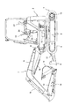
- BRIEF DESCRIPTION OF THE DRAWINGS It is a hydraulic-circuit figure showing the structure of the drive device of the hydraulic shovel in one Embodiment of this invention. It is a figure showing the relationship between the lever stroke of the operating device for blades in one embodiment of this invention, and the pilot pressure for blade lowering. It is a flowchart showing the processing procedure of the controller in one embodiment of the present invention. It is a side view showing the state where the body of the hydraulic shovel in one embodiment of the present invention is jacked up.
- FIG. 1 is a side view showing a structure of a hydraulic shovel in the present embodiment.
- the hydraulic shovel of the present embodiment includes a self-propelled lower traveling body 1 and an upper swing body 2 rotatably provided on the upper side of the lower travel body 1, and the lower traveling body 1 and the upper swing body 2 Make up the car body.
- the upper swing body 2 is swung by the swing motor 13.
- the undercarriage 1 includes an H-shaped track frame 3 as viewed from above.
- the track frame 3 is provided on the center frame extending in the left-right direction (vertical direction with respect to the paper surface in FIG. 1) and on the left side of the center frame (front side toward the paper surface in FIG. 1)
- the left side frame extends in the middle and left and right directions
- the right side frame is provided on the right side of the center frame (rear side in the plane of FIG. 1) and extends in the front and rear direction.
- the left crawler type traveling device 4 is provided on the left side frame, and is driven by the left traveling motor 15.
- the right crawler traveling device 5 (see FIG. 5 described later) is provided on the right side frame, and is driven by the right traveling motor 17 (see FIG. 5 described later).
- the lower traveling body 1 travels by driving the left and right traveling devices 4 and 5.
- the blade 6 is provided to be drivable in the vertical direction (vertical direction in FIG. 1) with respect to the center frame, and is driven by the blade cylinder 12 in the vertical direction.
- the working device 7 is connected to the front side (left side in FIG. 1) of the upper swing body 2.
- the work device 7 includes a swing post 8 pivotally connected to the upper swing body 2 in the lateral direction, a boom 9 pivotally connected to the swing post 8 in the vertical direction, and a boom 9 in the vertical direction.
- the arm 10 is movably connected, and the bucket 11 is rotatably connected to the arm 10 in the vertical direction.
- the swing post 8 is pivoted in the left-right direction by a swing cylinder 14 (see FIG. 2 described later) to swing the boom 9 in the left-right direction.
- the boom 9, the arm 10 and the bucket 11 are vertically rotated by the boom cylinder 18, the arm cylinder 16 and the bucket cylinder 19, respectively.
- FIG. 2 is a diagram showing the configuration of the drive device of the hydraulic shovel in the present embodiment.
- the drive device of the present embodiment includes hydraulic pumps P1, P2 and P3 which are main pumps driven by the engine 20 (motor), and a plurality of actuators operated by pressure oil discharged from the hydraulic pump P1 (specifically, The right traveling motor 17, boom cylinder 18, and bucket cylinder 19 described above, and a plurality of actuators operated by pressure oil discharged from the hydraulic pump P2 (specifically, the left traveling motor 15 and arm cylinder 16 described above) And a plurality of actuators (more specifically, the above-described blade cylinder 12, the swing motor 13, and the swing cylinder 14) operated by pressure oil discharged from the hydraulic pump P3 and a valve unit 21.
- the hydraulic pumps P1 and P2 are configured of split flow type hydraulic pumps.
- the valve unit 21 includes open-center control valves 27, 28, 29 for controlling the flow of pressure oil from the hydraulic pump P1 to the actuators 17, 18, 19, and pressure oil from the hydraulic pump P2 to the actuators 15, 16. And control valves 22 and 23 for controlling the flow of hydraulic fluid from the hydraulic pump P3 to the actuators 12, 13 and 14, respectively.
- Main relief valves 30a, 30b, and 30c are provided to limit the discharge pressure of the hydraulic pumps P1, P2, and P3, respectively.
- the drive device of the present embodiment includes a pilot pump P4 driven by the engine 20, a pilot relief valve 31 for keeping the discharge pressure of the pilot pump P4 constant, and operating devices 32 to 36 for operating the control valves 22 to 29. And have.
- the operating device 33 is disposed on the left side of the driver's seat 37 (see FIG. 1) in the driver's cab of the upper swing body 2, and the operating devices 32 and 34 are disposed on the right side of the driver's seat 37.
- the operating devices 35 and 36 are disposed on the front side of the driver's seat 37.
- the boom and bucket operating device 32 has a cross-operation type operating lever, and pilot valves 32a to 32d that operate according to the operation of the operating lever.
- the pilot valve 32a operates in response to the rear operation of the control lever, generates a pilot pressure a for boom raising based on the discharge pressure of the pilot pump P4, and controls the boom for the pilot pressure a for boom raising.
- the pressure is output to one pressure receiving portion of the valve 28.
- the boom control valve 28 is switched to supply the pressure oil from the hydraulic pump P1 to the bottom side oil chamber of the boom cylinder 18, and the boom cylinder 18 is extended. As a result, the boom 9 is raised.
- the pilot valve 32b operates in response to the front side operation of the control lever and generates a pilot pressure b for lowering the boom based on the discharge pressure of the pilot pump P4, and the pilot pressure b for lowering the boom is used as a control valve for the boom Output to the other side pressure receiving unit of 28.
- the boom control valve 28 is switched to supply the pressure oil from the hydraulic pump P1 to the rod side oil chamber of the boom cylinder 18, and the boom cylinder 18 is shortened. As a result, the boom 9 is lowered.
- the pilot valve 32c operates in response to the left operation of the control lever, and generates a pilot pressure c for the bucket cloud based on the discharge pressure of the pilot pump P4, and the pilot pressure c for the bucket cloud is used as a control valve for the bucket Output to 29 one side pressure receiving part.
- the control valve 29 for buckets is switched, the pressure oil from the hydraulic pump P1 is supplied to the bottom side oil chamber of the bucket cylinder 19, and the bucket cylinder 19 is extended. As a result, the bucket 11 is made to cloud.
- the pilot valve 32d operates in response to the right-hand operation of the control lever and generates a pilot pressure d for bucket dumping based on the discharge pressure of the pilot pump P4, and the pilot pressure d for bucket dumping is used as a control valve for buckets Output to the other side pressure receiving section of 29.
- the control valve 29 for buckets is switched, the pressure oil from the hydraulic pump P1 is supplied to the rod side oil chamber of the bucket cylinder 19, and the bucket cylinder 19 is contracted. As a result, the bucket 11 is dumped.
- the arm and pivoting operation device 33 has a cross-operation type operation lever and pilot valves 33a to 33d which operate according to the operation of the operation lever.
- the pilot valve 33a operates in response to the rear operation of the control lever and generates a pilot pressure e for pulling the arm based on the pressure of the pilot pump P4, and the pilot pressure e for pulling the arm is used as a control valve for the arm Output to the one side pressure receiving section of 26.
- the arm control valve 26 is switched to supply the pressure oil from the hydraulic pump P2 to the bottom side oil chamber of the arm cylinder 16, and the arm cylinder 16 is extended. As a result, the arm 10 is retracted.
- the pilot valve 33b operates in response to the front side operation of the control lever, and generates a pilot pressure f for pushing the arm based on the pressure of the pilot pump P4, and the pilot pressure f for pushing the arm is used as the control valve 26 for the arm.
- the arm control valve 26 is switched to supply pressure oil from the hydraulic pump P2 to the rod side oil chamber of the arm cylinder 16, and the arm cylinder 16 is contracted. As a result, the arm 10 is pushed in.
- the pilot valve 33c operates in response to the left operation of the control lever and generates a pilot pressure g for left turning based on the pressure of the pilot pump P4, and the pilot pressure g for left turning is used as a control valve 23 for turning.
- the pilot valve 33d operates in response to the right operation of the control lever and generates a pilot pressure h for turning right based on the pressure of the pilot pump P4, and the pilot pressure h for turning right is controlled for turning The pressure is output to the other pressure receiving portion of the valve 23.
- the swing control valve 23 is switched to supply the pressure oil from the hydraulic pump P3 to the opposite port of the swing motor 13, and the swing motor 13 is rotated in the opposite direction.
- the upper swing body 2 is turned to the right.
- the operating device 35 for traveling includes a left operation member (specifically, an integrated unit of an operation lever and an operation pedal) operable in the front-rear direction, and a pilot valve that operates according to the operation of the left operation member. Pilot valves 35c and 35d that operate according to the operation of the right operation member 35a and 35b, the right operation member (specifically, an integrated control lever and an operation pedal integrated) that can be operated in the front and rear direction, and the right operation member And.
- the pilot valve 35a operates in response to the front operation of the left operation member and generates a pilot pressure i for left travel based on the discharge pressure of the pilot pump P4, and this pilot pressure i for left travel is used for left travel
- the pressure is output to one pressure receiving portion of the control valve 25.
- the left traveling control valve 25 is switched to supply the pressure oil from the hydraulic pump P2 to one port of the left traveling motor 15, and the left traveling motor 15 is rotated in one direction.
- the left traveling device 4 is driven in the traveling direction on one side (normally, the forward direction).
- the pilot valve 35b operates in response to the rear operation of the left operation member to generate a left traveling pilot pressure j based on the discharge pressure of the pilot pump P4, and travels the left traveling pilot pressure j to the left Output to the other pressure receiving portion of the control valve 25.
- the left traveling control valve 25 is switched to supply the pressure oil from the hydraulic pump P2 to the opposite port of the left traveling motor 15, and the left traveling motor 15 is rotated in the opposite direction.
- the left traveling device 4 is driven in the opposite traveling direction (usually the reverse direction).
- the pilot valve 35c operates in response to the front operation of the right operation member, and generates a pilot pressure k for right traveling based on the discharge pressure of the pilot pump P4. This pilot pressure k for right traveling is used for right traveling
- the pressure is output to one pressure receiving portion of the control valve 27.
- the control valve 27 for right traveling is switched, the pressure oil from the hydraulic pump P1 is supplied to one side port of the right traveling motor 17, and the right traveling motor 17 is rotated in one direction.
- the right traveling device 5 is driven in the traveling direction on one side (usually, the forward direction).
- the pilot valve 35d operates in response to the rear operation of the right operation member, generates a pilot pressure l for right traveling based on the discharge pressure of the pilot pump P4, and travels the pilot pressure l for right traveling to the right It outputs to the other side pressure receiving portion of the control valve 27.
- the right traveling control valve 27 is switched to supply the pressure oil from the hydraulic pump P1 to the opposite port of the right traveling motor 17, and the right traveling motor 17 is rotated in the opposite direction.
- the right traveling device 5 is driven in the opposite traveling direction (usually the reverse direction).
- the boom swing operation device 36 includes an operation pedal that can be operated in the left-right direction, and pilot valves 36a and 36b that operate according to the operation of the operation pedal.
- the pilot valve 36a operates in response to the left operation of the operation pedal and generates a pilot pressure m for the boom left swing based on the discharge pressure of the pilot pump P4.
- the pilot pressure m for the boom left swing is used as a boom swing Output to one side pressure receiving portion of the control valve 24.
- the boom swing control valve 24 is switched to supply pressure oil from the hydraulic pump P3 to the bottom side oil chamber of the swing cylinder 14, and the swing cylinder 14 is extended.
- the boom 9 is made to swing left together with the swing post 8.
- the pilot valve 36b operates in response to the right operation of the operation pedal, generates a pilot pressure n for the boom right swing based on the discharge pressure of the pilot pump P4, and swings the pilot pressure n for the boom right swing Output to the other pressure receiving portion of the control valve 24.
- the boom swing control valve 24 is switched to supply the pressurized oil from the hydraulic pump P3 to the rod side oil chamber of the swing cylinder 14, and the swing cylinder 14 is contracted.
- the boom 9 is swung to the right together with the swing post 8.
- the operating device 34 for blades has an operating lever that can be operated in the front-rear direction, and pilot valves 34a and 34b that operate according to the operation of the operating lever.
- the pilot valve 34a operates in response to the rear operation of the control lever to generate a pilot pressure p for raising the blade based on the pressure of the pilot pump P4, and the pilot pressure p for raising the blade is used as a control valve for the blade. It outputs to the one side pressure receiving part 22 through the pilot oil passage 38a.
- the blade control valve 22 is switched from the neutral position I to the raising position II (switching position) to supply the pressure oil from the hydraulic pump P3 to the rod side oil chamber of the blade cylinder 12 and shorten the blade cylinder 12 .
- the blade 6 is raised.
- the pilot valve 34b operates in response to the front side operation of the control lever, and generates a pilot pressure o for lowering the blade based on the pressure of the pilot pump P4, and the pilot pressure o for lowering the blade is used as the control valve 22 for the blade.
- the pressure is output to the other side pressure receiving portion of the engine via the pilot oil passage 38b.
- the blade control valve 22 is switched from the neutral position I to the lowered position III (switching position) to supply the pressure oil from the hydraulic pump P3 to the bottom side oil chamber of the blade cylinder 12 and extend the blade cylinder 12 .
- the blade 6 is lowered.
- the drive device of the present embodiment is configured to be able to float the blade 6. More specifically, a branch oil passage 39a branched from the oil supply and discharge passage connected between the blade control valve 22 and the bottom side oil chamber of the blade cylinder 12, the blade control valve 22 and the rod side of the blade cylinder 12 A branch oil passage 39b branched from an oil supply / discharge oil passage connected between oil chambers, a float valve 41 (electromagnetic valve) provided between the branch oil passages 39a and 39b and the tank side oil passage 40, and a float And a controller 42 for controlling the valve 41.
- a branch oil passage 39a branched from the oil supply and discharge passage connected between the blade control valve 22 and the bottom side oil chamber of the blade cylinder 12, the blade control valve 22 and the rod side of the blade cylinder 12
- a branch oil passage 39b branched from an oil supply / discharge oil passage connected between oil chambers
- a float valve 41 electromagagnetic valve
- the controller 42 includes an arithmetic control unit (for example, a CPU) that executes arithmetic processing and control processing based on a program, and a storage unit (for example, a ROM and a RAM) that stores programs and results of the arithmetic processing.
- arithmetic control unit for example, a CPU
- a storage unit for example, a ROM and a RAM
- the float valve 41 is switchable between the standard position IV and the float position V.
- the branch oil passages 39a and 39b and the tank oil passage 40 are shut off.
- the blade cylinder 12 can be driven by switching the blade control valve 22.
- the branch oil passages 39a and 39b are communicated with the tank oil passage 40. That is, the bottom side oil chamber and the rod side oil chamber of the blade cylinder 12 are communicated with the tank T. This causes the blade 6 to float.
- the blade operating device 34 incorporates a float instruction device for performing a float instruction to make the blade 6 float, and the predetermined operation lever is on the front side (in other words, in the blade lowering direction).
- the float instruction can be performed when the operation is performed beyond the stroke.
- the pilot valve 34b raises the pilot pressure o for lowering the blade as the lever stroke increases.
- the pilot pressure o for lowering the blade is rapidly increased to a maximum value Pmax, and a preset threshold Pi (for example, 3 MPa Over).
- a pilot pressure sensor 43 is provided in the blade lowering pilot oil passage 38b, and the controller 42 determines whether the blade lowering pilot pressure o detected by the pilot pressure sensor 43 is equal to or higher than a threshold Pi. It is determined whether or not a float instruction has been issued.
- the pilot oil passage 38 b is provided with the switching valve 44 (electromagnetic valve), and the controller 42 controls the switching valve 44 in conjunction with the float valve 41.
- the switching valve 44 is switchable between the communication position VI and the blocking position VII.
- the blade lowering pilot pressure o can be output from the blade operating device 34 to the other pressure receiving portion of the blade control valve 22, and the blade control valve by the blade operating device 34 22 operations become effective.
- the switching valve 44 is in the blocking position VII, the blade lowering pilot pressure o can not be output from the blade operating device 34 to the other pressure receiving portion of the blade control valve 22.
- the operation of the control valve 22 is invalidated.
- a pressure sensor 45 for detecting the pressure in the bottom side oil chamber of the blade cylinder 12 is provided, and the controller 42 controls the blade 6 to jack the vehicle body based on the detection result of the pilot pressure sensor 43. It is determined whether it is in the up state.
- FIG. 3 is a flowchart showing the processing procedure of the controller in this embodiment.
- the controller 42 determines, based on the detection result of the pressure sensor 45, whether or not the blade 6 is in a state of jacking up the vehicle body.
- the blade 6 is a vehicle body depending on whether or not the pressure in the bottom side oil chamber of the blade cylinder 12 is equal to or higher than a preset reference value (for example 10 MPa) and the state continues for a predetermined time (for example several minutes). It is judged whether or not it is in the state of jacking up.
- step S101 the controller 42 determines that the blade 6 is in a jackup state of the vehicle body.
- step S101 the determination in step S101 is YES, and the process proceeds to step S102.
- step S102 the controller 42 turns the control signal of the float valve 41 OFF and holds the float valve 41 at the standard position IV regardless of the presence or absence of a float instruction. Further, regardless of the presence or absence of the float instruction, the control signal of the switching valve 44 is turned OFF, and the switching valve 44 is held at the communication position VI. Thereafter, the process returns to step S101 to perform the above-described process.
- step S101 determines that the blade 6 is not in a state of jacking up the vehicle body.
- step S101 determines whether or not a float instruction has been issued based on whether or not the pilot pressure o for lowering the blade detected by the pilot pressure sensor 43 is equal to or higher than a threshold Pi.
- step S103 determines that the float instruction is not performed.
- the determination in step S103 is NO, and the process proceeds to step S102 to perform the above-described processing.
- step S104 the controller 42 turns on the control signal of the float valve 41 to switch the float valve 41 to the float position V. Further, the control signal of the switching valve 44 is turned ON to switch the switching valve 44 to the shutoff position VII.
- step S101 if the blade 6 is in the float state (if the float valve 41 is in the float position V and the switching valve 44 is in the shut off position VII), the controller 42 determines whether the blade 6 is jacking up the vehicle body. It does not decide whether or not. The reason is that the pressure in the bottom side oil chamber of the blade cylinder 12 may exceed the reference value when the leveling operation is performed by the blade 6 in the float state.
- the blade 6 of the hydraulic shovel is used, for example, when jacking up the vehicle body to maintain or clean the underbody of the vehicle body or when performing a leveling operation.
- the controller 42 determines that the blade 6 is in the state of jacking up the vehicle body. In this case, even if the operator erroneously gives a float instruction with the blade operating device 34, the controller 42 proceeds to step S102 through step S101 of FIG. 4 described above and holds the float valve 41 at the standard position IV. , The switching valve 44 is held at the communication position VI. At the standard position IV of the float valve 41, the blade cylinder 12 can be driven and the blade 6 is not floated.
- the bottom side oil chamber and the rod side oil chamber of the blade cylinder 12 are communicated with the tank T. Thereby, the blade 6 is in a floating state. At this time, the blade 6 descends by its own weight and contacts the ground. Then, when the operator operates the operating device 35 to move the hydraulic shovel forward or backward, since the blade 6 is in a floating state, even if the ground is rough, the shape can be made to follow. Therefore, a good leveling operation can be performed.
- the float valve 41 is held at the standard position IV even when the operator erroneously gives a float instruction by the blade operating device 34 when the vehicle is jacked up. That is, since the blade 6 is not floated, descent of the vehicle body can be prevented.
- the float valve 41 is switched to the float position V. That is, since the bottom side oil chamber and the rod side oil chamber of the blade cylinder 12 are communicated with the tank T to make the blade 6 float, a good leveling operation can be performed.
- the switching valve 44 By switching to the blocking position VII, the operation of the blade control valve 22 by the blade operating device 34 is invalidated. That is, the blade control valve 22 is held at the neutral position I.
- the pressure oil from the hydraulic pump P3 is transferred to the tank T via the blade control valve 22 and the float valve 41. Instead, it is supplied to other control valves (in this embodiment, the control valve 23 for turning and the control valve 24 for boom swing). Therefore, even when the blade 6 is floated, pressure oil can be supplied to the other actuator (in the present embodiment, the swing motor 13 or the swing cylinder 14) through the other control valve described above, and the other actuator Can be driven.
- valve unit 21 when remodeling the existing hydraulic shovel so that the blade 6 can be floated, the float valve 41, the controller 42, and the pilot pressure A sensor 43, a switching valve 44, and a pressure sensor 45 may be added. Therefore, remodeling of the existing hydraulic shovel can be easily performed.
- the float valve 41 is provided in the branched oil passages 39a and 39b respectively communicating with the bottom side oil chamber and the rod side oil chamber of the blade cylinder 12
- a float valve may be provided to intervene in both the oil passage. Then, when the float valve is at the standard position, the bottom side oil chamber and the rod side oil chamber of the blade cylinder 12 are communicated with the blade control valve 22. On the other hand, when the float valve is in the float position, the bottom side oil chamber and the rod side oil chamber of the blade cylinder 12 are communicated with the tank. Also in such a modification, the same effect as that of the above embodiment can be obtained.
- the pressure sensor 45 for detecting the pressure in the bottom oil chamber of the blade cylinder 12 is provided, and the pressure detected by the pressure sensor 45 is equal to or higher than a preset reference value and the state
- the controller 42 determines whether or not the blade 6 is in the jacking-up state of the vehicle body based on whether or not the blade 6 has continued for a predetermined time, the invention is not limited thereto. Variations are possible within the scope of the technical concept.
- a pressure sensor for detecting the pressure of the rod side oil chamber of the blade cylinder 12 is provided, and the pressure detected by this pressure sensor is less than a preset reference value and the state continues for a predetermined time
- the controller may determine whether or not the blade 6 is in the state of jacking up the vehicle body.
- a first pressure sensor for detecting the pressure in the bottom side oil chamber of the blade cylinder 12 and a second pressure sensor for detecting the pressure in the rod side oil chamber of the blade cylinder 12 are provided. Pressure is greater than or equal to a preset first reference value, and the pressure detected by the second pressure sensor is less than or equal to a preset second reference value (where second reference value ⁇ first reference value).
- the controller 6 may determine whether the blade 6 is in a state of jacking up the vehicle body. Also in these modifications, the same effect as that of the above embodiment can be obtained.
- the blade operating device 34 incorporates the float instruction device, and the switching valve 44 is provided only in the pilot oil passage 38b.
- the present invention is not limited to this. Modifications are possible within the spirit and scope of the present invention. That is, a float indication device (in detail, for example, a float switch) may be provided separately from the blade operation device, and two switching valves may be provided in the pilot oil passages 38a and 38b.
- a float indication device in detail, for example, a float switch
- two switching valves may be provided in the pilot oil passages 38a and 38b.
- the float valve 41 When it is determined that the blade 6 is jacking up the vehicle body, the float valve 41 is held at the standard position and the two switching valves are held at the communication position regardless of the presence or absence of the float instruction. Thus, the operation of the blade control valve 22 is enabled. Also in such a modification, the same effect as that of the above embodiment can be obtained.
- the blade operating device 34 generates the pilot pressure according to the stroke of the control lever and outputs the pilot pressure to the blade control valve 22 as an example.
- the present invention is not limited thereto. Modifications can be made without departing from the spirit and technical concept of the present invention. That is, the blade operating device 34 detects the stroke of the operating lever and outputs it to the controller, and the controller generates a control signal according to the stroke of the operating lever and outputs it to the electromagnetic proportional pressure reducing valve, and the electromagnetic proportional pressure reducing valve controls The pilot pressure may be generated according to the signal and output to the blade control valve. Then, the operation of the blade control valve 22 may be enabled or disabled by the controller performing processing to enable or disable the control signal instead of the switching valve 44 of the one embodiment. Also in such a modification, the same effect as that of the above embodiment can be obtained.
- control valves 22 to 29 are open center type, and the pressure oil from the hydraulic pumps P1, P2 and P3 is returned to the tank when the control valves 22 to 29 are in the neutral position.
- the open center system has been described as an example, the present invention is not limited to this, and modifications can be made without departing from the spirit and technical concept of the present invention. That is, the control valve is a closed center type, and the pressure oil from the hydraulic pump is returned to the tank via the unload valve when the control valves are in the neutral position (closed center with load sensing control function) System).
- the present invention is applied to a hydraulic shovel as an example, the present invention is not limited to this, and the present invention may be applied to another construction machine (for example, a wheel loader etc.) .
Landscapes
- Engineering & Computer Science (AREA)
- General Engineering & Computer Science (AREA)
- Mining & Mineral Resources (AREA)
- Civil Engineering (AREA)
- Structural Engineering (AREA)
- Physics & Mathematics (AREA)
- Mechanical Engineering (AREA)
- Fluid Mechanics (AREA)
- Acoustics & Sound (AREA)
- Electromagnetism (AREA)
- Optics & Photonics (AREA)
- Operation Control Of Excavators (AREA)
Abstract
Description
図4で示すように油圧ショベルの車体をジャッキアップする場合の動作について説明する。最初に、図1で示す油圧ショベルの状態であれば、オペレータは操作装置33を操作して上部旋回体2を180度反転させる。そして、オペレータは操作装置32,33を操作して作業装置7の姿勢を変更すると共にバケット11を地面に接触させる。そして、オペレータは操作装置32を操作してブーム9を下げさせることで、下部走行体1の後部を地面から浮き上がらせる。また、オペレータは操作装置34を操作して(但し、操作レバーがデテント位置に達しないように操作して)ブレード6を下げさせることで、下部走行体1の前部を地面から浮き上がらせる。これにより、車体のジャッキアップ状態となる。
ブレード6をフロート状態にして均し作業を行う場合の動作について説明する。ブレード6が車体をジャッキアップしている状態になければ、ブレードシリンダ12のボトム側油室の圧力が基準値未満となる。これにより、コントローラ42は、ブレード6が車体をジャッキアップしている状態にないと判定する。この場合に、オペレータがブレード用操作装置34でフロート指示を行えば、コントローラ42は、上述の図4のステップS101,S103を経てステップS104に進み、フロート弁41をフロート位置Vに切換えると共に、切換弁44を遮断位置VIIに切換える。
2 上部旋回体
6 ブレード
12 ブレードシリンダ
22 ブレード用制御弁
34 ブレード用操作装置
34a,34b パイロット弁
38a,38b パイロット油路
39a,39b 分岐油路
40 タンク側油路
41 フロート弁
42 コントローラ
43 パイロット圧センサ
44 切換弁
45 圧力センサ
P1,P2,P3 油圧ポンプ
T タンク
Claims (4)
- 車体に対して上下方向に駆動可能に設けられたブレードと、
油圧ポンプから吐出された圧油によって作動し、前記ブレードを上下方向に駆動するブレードシリンダと、
前記油圧ポンプから前記ブレードシリンダへの圧油の流れを制御するブレード用制御弁と、
前記ブレード用制御弁を操作するブレード用操作装置と、
前記ブレードをフロート状態にするフロート指示を行うフロート指示装置と、
前記ブレードシリンダのボトム側油室及びロッド側油室にそれぞれ通じる油路に設けられ、前記ブレードシリンダの駆動を可能とする標準位置と、前記ブレードシリンダのボトム側油室及びロッド側油室をタンクへ連通させて前記ブレードをフロート状態にするフロート位置とを有するフロート弁と、
前記ブレードシリンダのボトム側油室及びロッド側油室のうちの少なくとも一方の圧力を検出する圧力センサと、
前記圧力センサの検出結果に基づいて、前記ブレードが前記車体をジャッキアップしている状態にあるか否かを判定すると共に、前記フロート弁を制御するコントローラとを備えた建設機械において、
前記コントローラは、
前記ブレードが前記車体をジャッキアップしている状態にないと判定した場合は、前記フロート指示に応じて、前記フロート弁を前記フロート位置に切換えると共に、前記ブレード用操作装置による前記ブレード用制御弁の操作を無効化し、
前記ブレードが前記車体をジャッキアップしている状態にあると判定した場合は、前記フロート指示の有無にかかわらず、前記フロート弁を前記標準位置に保持すると共に、前記ブレード用操作装置による前記ブレード用制御弁の操作を有効化することを特徴とする建設機械。 - 請求項1に記載の建設機械において、
前記ブレード用操作装置は、操作レバーの操作に応じてパイロット圧を生成し、パイロット油路を介し前記ブレード用制御弁にパイロット圧を出力して前記ブレード用制御弁を操作するように構成されており、
前記パイロット油路には、遮断位置と連通位置を有する切換弁が設けられており、
前記コントローラは、
前記ブレードが前記車体をジャッキアップしている状態にないと判定した場合は、前記フロート指示に応じて、前記フロート弁を前記フロート位置に切換えると共に、前記切換弁を前記遮断位置に切換えて前記ブレード用制御弁の操作を無効化し、
前記ブレードが前記車体をジャッキアップしている状態にあると判定した場合は、前記フロート指示の有無にかかわらず、前記フロート弁を前記標準位置に保持すると共に、前記切換弁を前記連通位置に保持して前記ブレード用制御弁の操作を有効化することを特徴とする建設機械。 - 請求項1に記載の建設機械において、
前記ブレード用操作装置は、
操作レバーの一方側の操作に応じてブレード上げ用のパイロット圧を生成し、第1パイロット油路を介し前記ブレード用制御弁にブレード上げ用のパイロット圧を出力して前記ブレード用制御弁を操作する第1パイロット弁と、
前記操作レバーの反対側の操作に応じてブレード下げ用のパイロット圧を生成し、第2パイロット油路を介し前記ブレード用制御弁にブレード下げ用のパイロット圧を出力して前記ブレード用制御弁を操作する第2パイロット弁とを有しており、
前記フロート指示装置は、前記ブレード用操作装置に組込まれて、前記操作レバーを前記反対側に所定のストローク以上に操作した場合に前記フロート指示を行えるようになっており、
前記コントローラは、前記第2パイロット油路に設けられたパイロット圧センサで検出されたブレード下げ用のパイロット圧が予め設定された閾値以上であるときに、前記フロート指示が行われたと判定することを特徴とする建設機械。 - 請求項3に記載の建設機械において、
前記第2パイロット油路には、遮断位置と連通位置を有する切換弁が設けられており、
前記コントローラは、
前記ブレードが前記車体をジャッキアップしている状態にないと判定した場合は、前記フロート指示に応じて、前記フロート弁を前記フロート位置に切換えると共に、前記切換弁を前記遮断位置に切換えて前記ブレード用制御弁の操作を無効化し、
前記ブレードが前記車体をジャッキアップしている状態にあると判定した場合は、前記フロート指示の有無にかかわらず、前記フロート弁を前記標準位置に保持すると共に、前記切換弁を前記連通位置に保持して前記ブレード用制御弁の操作を有効化することを特徴とする建設機械。
Priority Applications (6)
| Application Number | Priority Date | Filing Date | Title |
|---|---|---|---|
| US16/328,345 US11332911B2 (en) | 2017-09-29 | 2017-09-29 | Construction machine |
| KR1020197003400A KR102131655B1 (ko) | 2017-09-29 | 2017-09-29 | 건설 기계 |
| CN201780049434.2A CN109996924B (zh) | 2017-09-29 | 2017-09-29 | 工程机械 |
| PCT/JP2017/035675 WO2019064557A1 (ja) | 2017-09-29 | 2017-09-29 | 建設機械 |
| EP17922074.4A EP3492659B1 (en) | 2017-09-29 | 2017-09-29 | Construction machine |
| JP2019510379A JP6687992B2 (ja) | 2017-09-29 | 2017-09-29 | 建設機械 |
Applications Claiming Priority (1)
| Application Number | Priority Date | Filing Date | Title |
|---|---|---|---|
| PCT/JP2017/035675 WO2019064557A1 (ja) | 2017-09-29 | 2017-09-29 | 建設機械 |
Publications (1)
| Publication Number | Publication Date |
|---|---|
| WO2019064557A1 true WO2019064557A1 (ja) | 2019-04-04 |
Family
ID=65903628
Family Applications (1)
| Application Number | Title | Priority Date | Filing Date |
|---|---|---|---|
| PCT/JP2017/035675 Ceased WO2019064557A1 (ja) | 2017-09-29 | 2017-09-29 | 建設機械 |
Country Status (6)
| Country | Link |
|---|---|
| US (1) | US11332911B2 (ja) |
| EP (1) | EP3492659B1 (ja) |
| JP (1) | JP6687992B2 (ja) |
| KR (1) | KR102131655B1 (ja) |
| CN (1) | CN109996924B (ja) |
| WO (1) | WO2019064557A1 (ja) |
Families Citing this family (6)
| Publication number | Priority date | Publication date | Assignee | Title |
|---|---|---|---|---|
| JP6560831B2 (ja) * | 2017-03-24 | 2019-08-14 | 株式会社日立建機ティエラ | 建設機械の油圧駆動装置 |
| WO2021010489A1 (ja) * | 2019-07-17 | 2021-01-21 | 住友建機株式会社 | 作業機械及び作業機械による作業を支援する支援装置 |
| JP7201878B2 (ja) * | 2020-03-27 | 2023-01-10 | 株式会社日立建機ティエラ | 建設機械の油圧駆動装置 |
| WO2023188963A1 (ja) * | 2022-03-31 | 2023-10-05 | 日立建機株式会社 | ホイール式建設機械 |
| US12606985B2 (en) | 2023-08-02 | 2026-04-21 | Deere & Company | Collision avoidance system for avoiding collision between movable components and portions of a work machine |
| EP4549669A1 (en) * | 2023-11-06 | 2025-05-07 | Yanmar Holdings Co., Ltd. | Method for controlling working machine and working machine |
Citations (2)
| Publication number | Priority date | Publication date | Assignee | Title |
|---|---|---|---|---|
| JP2002088796A (ja) | 2000-09-19 | 2002-03-27 | Kobelco Contstruction Machinery Ltd | ドーザ装置 |
| JP2009068173A (ja) * | 2007-09-10 | 2009-04-02 | Hitachi Constr Mach Co Ltd | 油圧ショベルの油圧システム |
Family Cites Families (9)
| Publication number | Priority date | Publication date | Assignee | Title |
|---|---|---|---|---|
| US4166506A (en) * | 1975-06-30 | 1979-09-04 | Kabushiki Kaisha Komatsu Seisakusho | Controlling apparatus for bulldozer blade |
| JPH0685449U (ja) * | 1993-05-24 | 1994-12-06 | 株式会社小松製作所 | 排土板制御装置 |
| JP4159551B2 (ja) | 2002-12-27 | 2008-10-01 | 日立建機株式会社 | 作業車両の油圧回路 |
| KR100849500B1 (ko) * | 2006-11-29 | 2008-07-31 | 볼보 컨스트럭션 이키프먼트 홀딩 스웨덴 에이비 | 플로팅 기능이 구비된 더블 체크밸브 |
| KR100915206B1 (ko) * | 2007-09-20 | 2009-09-02 | 볼보 컨스트럭션 이키프먼트 홀딩 스웨덴 에이비 | 플로팅 기능이 구비된 더블 체크밸브 |
| JP2009155893A (ja) * | 2007-12-26 | 2009-07-16 | Kobelco Contstruction Machinery Ltd | ショベルのドーザ装置 |
| KR20160023710A (ko) * | 2013-06-28 | 2016-03-03 | 볼보 컨스트럭션 이큅먼트 에이비 | 플로팅기능을 갖는 건설기계용 유압회로 및 플로팅기능 제어방법 |
| CN106704313B (zh) * | 2016-12-16 | 2018-02-06 | 上海中联重科桩工机械有限公司 | 旋挖钻机及桅杆液压控制系统和桅杆起升/下降控制方法 |
| JP6560831B2 (ja) * | 2017-03-24 | 2019-08-14 | 株式会社日立建機ティエラ | 建設機械の油圧駆動装置 |
-
2017
- 2017-09-29 CN CN201780049434.2A patent/CN109996924B/zh active Active
- 2017-09-29 US US16/328,345 patent/US11332911B2/en active Active
- 2017-09-29 EP EP17922074.4A patent/EP3492659B1/en active Active
- 2017-09-29 JP JP2019510379A patent/JP6687992B2/ja active Active
- 2017-09-29 KR KR1020197003400A patent/KR102131655B1/ko active Active
- 2017-09-29 WO PCT/JP2017/035675 patent/WO2019064557A1/ja not_active Ceased
Patent Citations (2)
| Publication number | Priority date | Publication date | Assignee | Title |
|---|---|---|---|---|
| JP2002088796A (ja) | 2000-09-19 | 2002-03-27 | Kobelco Contstruction Machinery Ltd | ドーザ装置 |
| JP2009068173A (ja) * | 2007-09-10 | 2009-04-02 | Hitachi Constr Mach Co Ltd | 油圧ショベルの油圧システム |
Non-Patent Citations (1)
| Title |
|---|
| See also references of EP3492659A4 |
Also Published As
| Publication number | Publication date |
|---|---|
| KR102131655B1 (ko) | 2020-07-08 |
| CN109996924B (zh) | 2021-04-06 |
| CN109996924A (zh) | 2019-07-09 |
| US20210332560A1 (en) | 2021-10-28 |
| US11332911B2 (en) | 2022-05-17 |
| EP3492659A1 (en) | 2019-06-05 |
| JPWO2019064557A1 (ja) | 2019-11-14 |
| JP6687992B2 (ja) | 2020-04-28 |
| EP3492659B1 (en) | 2022-05-04 |
| EP3492659A4 (en) | 2020-06-03 |
| KR20190041462A (ko) | 2019-04-22 |
Similar Documents
| Publication | Publication Date | Title |
|---|---|---|
| JP6687992B2 (ja) | 建設機械 | |
| KR102556315B1 (ko) | 쇼벨 | |
| US20170211597A1 (en) | Hydraulic system and method for controlling an implement of a working machine | |
| JP6560831B2 (ja) | 建設機械の油圧駆動装置 | |
| KR102056959B1 (ko) | 유압 제어 장치 및 이것을 구비한 건설 기계 | |
| WO2011061988A1 (ja) | 建設機械の油圧駆動装置 | |
| US7637039B2 (en) | Method and apparatus for controlling hydraulic pump for working machine of working vehicle | |
| JP6882214B2 (ja) | 建設機械 | |
| CN110462137B (zh) | 作业车辆 | |
| JP2010084784A (ja) | 作業機のフロート制御システム | |
| JP5274965B2 (ja) | 作業機のフロート制御システム | |
| JP6618366B2 (ja) | ホイールローダの荷役装置 | |
| JP5328279B2 (ja) | 作業機のフロート制御システム | |
| JP4436241B2 (ja) | 建設車両 | |
| KR20260057094A (ko) | 건설 기계 | |
| JP2021031964A (ja) | 建設機械 | |
| JP2020143452A (ja) | 建設機械 | |
| JP2010084330A (ja) | 作業機のフロート制御システム | |
| JP2010084331A (ja) | 作業機のフロート制御システム |
Legal Events
| Date | Code | Title | Description |
|---|---|---|---|
| ENP | Entry into the national phase |
Ref document number: 20197003400 Country of ref document: KR Kind code of ref document: A |
|
| ENP | Entry into the national phase |
Ref document number: 2019510379 Country of ref document: JP Kind code of ref document: A |
|
| ENP | Entry into the national phase |
Ref document number: 2017922074 Country of ref document: EP Effective date: 20190227 |
|
| 121 | Ep: the epo has been informed by wipo that ep was designated in this application |
Ref document number: 17922074 Country of ref document: EP Kind code of ref document: A1 |
|
| NENP | Non-entry into the national phase |
Ref country code: DE |