WO2019065524A1 - 金属壁材及びそれを用いた壁施工方法 - Google Patents
金属壁材及びそれを用いた壁施工方法 Download PDFInfo
- Publication number
- WO2019065524A1 WO2019065524A1 PCT/JP2018/035136 JP2018035136W WO2019065524A1 WO 2019065524 A1 WO2019065524 A1 WO 2019065524A1 JP 2018035136 W JP2018035136 W JP 2018035136W WO 2019065524 A1 WO2019065524 A1 WO 2019065524A1
- Authority
- WO
- WIPO (PCT)
- Prior art keywords
- wall material
- metal wall
- metal
- main body
- projecting rib
- Prior art date
- Legal status (The legal status is an assumption and is not a legal conclusion. Google has not performed a legal analysis and makes no representation as to the accuracy of the status listed.)
- Ceased
Links
Images





Classifications
-
- E—FIXED CONSTRUCTIONS
- E04—BUILDING
- E04F—FINISHING WORK ON BUILDINGS, e.g. STAIRS, FLOORS
- E04F13/00—Coverings or linings, e.g. for walls or ceilings
- E04F13/07—Coverings or linings, e.g. for walls or ceilings composed of covering or lining elements; Sub-structures therefor; Fastening means therefor
- E04F13/08—Coverings or linings, e.g. for walls or ceilings composed of covering or lining elements; Sub-structures therefor; Fastening means therefor composed of a plurality of similar covering or lining elements
- E04F13/0801—Separate fastening elements
- E04F13/0832—Separate fastening elements without load-supporting elongated furring elements between wall and covering elements
- E04F13/0833—Separate fastening elements without load-supporting elongated furring elements between wall and covering elements not adjustable
- E04F13/0835—Separate fastening elements without load-supporting elongated furring elements between wall and covering elements not adjustable the fastening elements extending into the back side of the covering elements
- E04F13/0837—Separate fastening elements without load-supporting elongated furring elements between wall and covering elements not adjustable the fastening elements extending into the back side of the covering elements extending completely through the covering elements
-
- E—FIXED CONSTRUCTIONS
- E04—BUILDING
- E04F—FINISHING WORK ON BUILDINGS, e.g. STAIRS, FLOORS
- E04F13/00—Coverings or linings, e.g. for walls or ceilings
- E04F13/07—Coverings or linings, e.g. for walls or ceilings composed of covering or lining elements; Sub-structures therefor; Fastening means therefor
- E04F13/08—Coverings or linings, e.g. for walls or ceilings composed of covering or lining elements; Sub-structures therefor; Fastening means therefor composed of a plurality of similar covering or lining elements
- E04F13/0801—Separate fastening elements
- E04F13/0832—Separate fastening elements without load-supporting elongated furring elements between wall and covering elements
-
- E—FIXED CONSTRUCTIONS
- E04—BUILDING
- E04C—STRUCTURAL ELEMENTS; BUILDING MATERIALS
- E04C2/00—Building elements of relatively thin form for the construction of parts of buildings, e.g. sheet materials, slabs, or panels
- E04C2/02—Building elements of relatively thin form for the construction of parts of buildings, e.g. sheet materials, slabs, or panels characterised by specified materials
- E04C2/26—Building elements of relatively thin form for the construction of parts of buildings, e.g. sheet materials, slabs, or panels characterised by specified materials composed of materials covered by two or more of groups E04C2/04, E04C2/08, E04C2/10 or of materials covered by one of these groups with a material not specified in one of the groups
- E04C2/284—Building elements of relatively thin form for the construction of parts of buildings, e.g. sheet materials, slabs, or panels characterised by specified materials composed of materials covered by two or more of groups E04C2/04, E04C2/08, E04C2/10 or of materials covered by one of these groups with a material not specified in one of the groups at least one of the materials being insulating
- E04C2/292—Building elements of relatively thin form for the construction of parts of buildings, e.g. sheet materials, slabs, or panels characterised by specified materials composed of materials covered by two or more of groups E04C2/04, E04C2/08, E04C2/10 or of materials covered by one of these groups with a material not specified in one of the groups at least one of the materials being insulating composed of insulating material and sheet metal
-
- E—FIXED CONSTRUCTIONS
- E04—BUILDING
- E04D—ROOF COVERINGS; SKY-LIGHTS; GUTTERS; ROOF-WORKING TOOLS
- E04D1/00—Roof covering by making use of tiles, slates, shingles, or other small roofing elements
- E04D1/12—Roofing elements shaped as plain tiles or shingles, i.e. with flat outer surface
- E04D1/18—Roofing elements shaped as plain tiles or shingles, i.e. with flat outer surface of metal
-
- E—FIXED CONSTRUCTIONS
- E04—BUILDING
- E04D—ROOF COVERINGS; SKY-LIGHTS; GUTTERS; ROOF-WORKING TOOLS
- E04D1/00—Roof covering by making use of tiles, slates, shingles, or other small roofing elements
- E04D1/24—Roofing elements with cavities, e.g. hollow tiles
-
- E—FIXED CONSTRUCTIONS
- E04—BUILDING
- E04D—ROOF COVERINGS; SKY-LIGHTS; GUTTERS; ROOF-WORKING TOOLS
- E04D1/00—Roof covering by making use of tiles, slates, shingles, or other small roofing elements
- E04D1/28—Roofing elements comprising two or more layers, e.g. for insulation
-
- E—FIXED CONSTRUCTIONS
- E04—BUILDING
- E04F—FINISHING WORK ON BUILDINGS, e.g. STAIRS, FLOORS
- E04F13/00—Coverings or linings, e.g. for walls or ceilings
- E04F13/07—Coverings or linings, e.g. for walls or ceilings composed of covering or lining elements; Sub-structures therefor; Fastening means therefor
- E04F13/08—Coverings or linings, e.g. for walls or ceilings composed of covering or lining elements; Sub-structures therefor; Fastening means therefor composed of a plurality of similar covering or lining elements
- E04F13/0864—Coverings or linings, e.g. for walls or ceilings composed of covering or lining elements; Sub-structures therefor; Fastening means therefor composed of a plurality of similar covering or lining elements composed of superposed elements which overlap each other and of which the flat outer surface includes an acute angle with the surface to cover
-
- E—FIXED CONSTRUCTIONS
- E04—BUILDING
- E04F—FINISHING WORK ON BUILDINGS, e.g. STAIRS, FLOORS
- E04F13/00—Coverings or linings, e.g. for walls or ceilings
- E04F13/07—Coverings or linings, e.g. for walls or ceilings composed of covering or lining elements; Sub-structures therefor; Fastening means therefor
- E04F13/08—Coverings or linings, e.g. for walls or ceilings composed of covering or lining elements; Sub-structures therefor; Fastening means therefor composed of a plurality of similar covering or lining elements
- E04F13/0866—Coverings or linings, e.g. for walls or ceilings composed of covering or lining elements; Sub-structures therefor; Fastening means therefor composed of a plurality of similar covering or lining elements composed of several layers, e.g. sandwich panels or layered panels
-
- E—FIXED CONSTRUCTIONS
- E04—BUILDING
- E04F—FINISHING WORK ON BUILDINGS, e.g. STAIRS, FLOORS
- E04F13/00—Coverings or linings, e.g. for walls or ceilings
- E04F13/07—Coverings or linings, e.g. for walls or ceilings composed of covering or lining elements; Sub-structures therefor; Fastening means therefor
- E04F13/08—Coverings or linings, e.g. for walls or ceilings composed of covering or lining elements; Sub-structures therefor; Fastening means therefor composed of a plurality of similar covering or lining elements
- E04F13/0875—Coverings or linings, e.g. for walls or ceilings composed of covering or lining elements; Sub-structures therefor; Fastening means therefor composed of a plurality of similar covering or lining elements having a basic insulating layer and at least one covering layer
-
- E—FIXED CONSTRUCTIONS
- E04—BUILDING
- E04F—FINISHING WORK ON BUILDINGS, e.g. STAIRS, FLOORS
- E04F13/00—Coverings or linings, e.g. for walls or ceilings
- E04F13/07—Coverings or linings, e.g. for walls or ceilings composed of covering or lining elements; Sub-structures therefor; Fastening means therefor
- E04F13/08—Coverings or linings, e.g. for walls or ceilings composed of covering or lining elements; Sub-structures therefor; Fastening means therefor composed of a plurality of similar covering or lining elements
- E04F13/12—Coverings or linings, e.g. for walls or ceilings composed of covering or lining elements; Sub-structures therefor; Fastening means therefor composed of a plurality of similar covering or lining elements of metal or with an outer layer of metal or enameled metal
-
- E—FIXED CONSTRUCTIONS
- E04—BUILDING
- E04D—ROOF COVERINGS; SKY-LIGHTS; GUTTERS; ROOF-WORKING TOOLS
- E04D1/00—Roof covering by making use of tiles, slates, shingles, or other small roofing elements
- E04D1/34—Fastenings for attaching roof-covering elements to the supporting elements
- E04D2001/3408—Fastenings for attaching roof-covering elements to the supporting elements characterised by the fastener type or material
- E04D2001/3423—Nails, rivets, staples or straps piercing or perforating the roof covering material
-
- E—FIXED CONSTRUCTIONS
- E04—BUILDING
- E04D—ROOF COVERINGS; SKY-LIGHTS; GUTTERS; ROOF-WORKING TOOLS
- E04D1/00—Roof covering by making use of tiles, slates, shingles, or other small roofing elements
- E04D1/34—Fastenings for attaching roof-covering elements to the supporting elements
- E04D2001/347—Fastenings for attaching roof-covering elements to the supporting elements characterised by the fastening pattern
- E04D2001/3473—Fastenings for attaching roof-covering elements to the supporting elements characterised by the fastening pattern fastening single roof elements to the roof structure with or without indirect clamping of neighbouring roof covering elements
-
- E—FIXED CONSTRUCTIONS
- E04—BUILDING
- E04D—ROOF COVERINGS; SKY-LIGHTS; GUTTERS; ROOF-WORKING TOOLS
- E04D1/00—Roof covering by making use of tiles, slates, shingles, or other small roofing elements
- E04D1/34—Fastenings for attaching roof-covering elements to the supporting elements
- E04D2001/3488—Fastenings for attaching roof-covering elements to the supporting elements characterised by the type of roof covering elements being fastened
- E04D2001/3494—Fastenings for attaching roof-covering elements to the supporting elements characterised by the type of roof covering elements being fastened made of rigid material having a flat external surface
-
- E—FIXED CONSTRUCTIONS
- E04—BUILDING
- E04F—FINISHING WORK ON BUILDINGS, e.g. STAIRS, FLOORS
- E04F13/00—Coverings or linings, e.g. for walls or ceilings
- E04F13/07—Coverings or linings, e.g. for walls or ceilings composed of covering or lining elements; Sub-structures therefor; Fastening means therefor
- E04F13/08—Coverings or linings, e.g. for walls or ceilings composed of covering or lining elements; Sub-structures therefor; Fastening means therefor composed of a plurality of similar covering or lining elements
- E04F13/0801—Separate fastening elements
- E04F13/0832—Separate fastening elements without load-supporting elongated furring elements between wall and covering elements
- E04F13/0833—Separate fastening elements without load-supporting elongated furring elements between wall and covering elements not adjustable
- E04F13/0851—Hooking means on the back side of the covering elements
Definitions
- the present invention relates to a metal wall material that is tightened to a roof foundation by driving a tightening member and a wall construction method using the metal wall material.
- Patent Document 1 a double layer facing material as shown in Patent Document 1 below, that is, a metal front substrate, a back substrate disposed on the back side of the front substrate, and a front substrate.
- a metal wall material provided with a core material made of a foamed resin, which is filled between the metal and the back substrate.
- Such a metal wall material after being placed on the wall base, is tightened to the wall base by driving a binding member such as a nail or a screw.
- the pressure resulting from the driving of the binding member may cause a dent or buckling around the driving position of the binding member.
- Such depression or buckling causes retention of water such as rainwater which causes corrosion of the metal wall material and deterioration of the design of the metal wall material.
- a method of preventing dents or buckling a method of increasing the thickness of the front substrate may be considered, but such a method causes an increase in wall weight.
- the present invention has been made to solve the problems as described above, and an object thereof is to provide a metal wall material capable of reducing the depression or buckling of a front substrate due to the driving of a binding member and the metal wall material It is to provide a wall construction method that was
- the metal wall material according to the present invention comprises a front substrate having a main body portion formed of a metal plate as a material and formed in a box shape, and a back substrate disposed on the back side of the front substrate so as to close the opening of the main body portion.
- a metal wall material provided with a core material filled between the main body portion and the back base material, and tightened to the wall base by the driving of the binding member into the main body portion, and disposed along the polygonal side
- a projecting rib consisting of at least one projection provided or arranged along a circle is provided on the top plate portion of the main body, and the binding member is driven into the inner region of the projecting rib Is configured.
- a front substrate having a main body portion formed of a metal plate in a box shape, and a back base disposed on the back side of the front substrate so as to close the opening of the main body portion.
- Material and a core material filled between the main body portion and the back substrate, and comprising at least one protrusion disposed along the sides of the polygon or disposed along a circle A wall construction method using a metal wall material in which a projecting rib is provided on a top plate portion of a main body, the step of disposing the metal wall material on a wall base, and a tension member in an inner region of the projecting rib And tightening the metal wall material on the wall substrate.
- a projecting rib having at least one protrusion disposed along a side of a polygon or disposed along a circle is It is provided on the top plate portion of the main body portion, and since the binding member is driven into the inner region of the projecting rib, it is possible to reduce the dent or buckling of the front substrate due to the driving of the binding member.
- FIG. 3 is a cross-sectional view of the metal wall material taken along line III-III of FIG.
- FIG. 7 is a cross-sectional view taken along line VII-VII of FIG. 6;
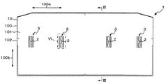
- Embodiment. 1 is a front view showing a metal wall material 1 according to an embodiment of the present invention
- FIG. 2 is a rear view showing the metal wall material 1 of FIG. 1
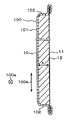
- FIG. 3 is along line III-III of FIG. 4 is a cross-sectional view of the metal wall material 1
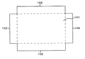
- FIG. 4 is an explanatory view showing another aspect of the main body 100 of FIG. 1
- FIG. 5 is a wall construction structure and a wall construction method using the metal wall material 1 of FIG. FIG.
- the metal wall material 1 shown in FIG. 1 to FIG. 3 is, as shown in FIG. 5, arranged together with other metal wall materials on the wall foundation of a building such as a house. As particularly shown in FIG. 3, the metal wall material 1 has a front substrate 10, a back substrate 11 and a core material 12.
- the front substrate 10 is made of a metal plate and is a member that appears on the outer surface of the wall when the metal wall material 1 is disposed on the wall substrate.
- a metal plate which is a material of the surface base material 10 a hot-dip galvanized steel sheet, a hot-dip aluminum plated steel plate, a hot-dip galvanized steel sheet, a hot-dip galvanized stainless steel sheet, a stainless steel plate, an aluminum plate, a Ti plate, a hot-dip galvanized steel sheet It is possible to use a plated steel plate, a painted molten Al plated steel plate, a painted molten Zn-based plated stainless steel plate, a painted molten Al plated stainless steel plate, a painted stainless steel plate, a painted Al plate or a painted Ti plate.
- the thickness of the metal plate is preferably 0.5 mm or less. As the thickness of the metal plate increases, the strength of the wall material increases while the weight increases. By setting the thickness of the metal plate to 0.5 mm or less, it is possible to prevent the weight of the metal wall material 1 from becoming too large. In addition, it is preferable that the thickness of a metal plate is 0.27 mm or more. By setting the thickness of the metal plate to 0.27 mm or more, the strength required as the wall can be secured, and the wind pressure resistance performance can be sufficiently obtained. Wind pressure resistance is the ability of the metal wall 1 to withstand without buckling against strong winds.
- the front substrate 10 has a box-shaped main body 100 having a top plate 101 and a peripheral wall 102.
- the main body portion 100 is preferably formed by subjecting a metal plate to a drawing process or an extrusion process.
- the peripheral wall portion 102 can be a wall surface continuous in the circumferential direction of the front surface base material 10, and moisture can infiltrate into the main body portion 100 You can reduce the sex.
- the circumferential wall portion 102 is a wall surface continuing in the circumferential direction of the surface base material 10, and the hardness of the circumferential wall portion 102 is enhanced by work hardening, whereby the wind pressure performance of the metal wall material 1 is significantly improved.
- the back substrate 11 is a member disposed on the back side of the front substrate 10 so as to close the opening of the main body 100.
- a lightweight material such as aluminum foil, aluminum-deposited paper, aluminum hydroxide paper, calcium carbonate paper, resin film or glass fiber paper can be used. By using these lightweight materials for the back substrate 11, it is possible to prevent the weight of the metal wall material 1 from increasing.
- the core material 12 is made of, for example, a foamed resin or the like, and is filled between the main body portion 100 of the front substrate 10 and the back substrate 11.
- the core material 12 is filled between the main body portion 100 and the back base material 11 to make the core material inside the main body portion 100 rather than a mode in which a backing material such as a resin sheet is attached to the back side of the front base material 10 12 can be firmly adhered, and the performance required for wall materials such as rain noise and heat insulation can be improved.
- height h of the main-body part 100 with which the core material 12 is filled be 4 mm or more and 8 mm or less.
- the strength of the main body 100 can be sufficiently increased, and the wind pressure resistance can be improved.
- the heat insulation property is also good at 4 mm or more.
- the height h of the main body 100 to 8 mm or less, it is possible to prevent the organic mass of the core material 12 from becoming too large and to obtain the non-combustible material recognition more reliably.
- the metal wall material 1 is extended along the direction 4 in which the width direction 100a (longitudinal direction) of the main body 100 is parallel to the eaves of the wall, and the depth direction 100b (described later) of the main body 100
- the latitudinal direction is adapted to extend along the vertical direction 5 of the wall.
- Each metal wall material 1 is tightened to the wall base by driving a tightening member such as a screw or a nail, for example.
- the lower metal wall material 1 is disposed on the wall base while being overlapped on the lower metal wall material 1 in the vertical direction 5.
- FIG. 6 is an enlarged plan view showing area VI of FIG. 1
- FIG. 7 is a cross-sectional view taken along line VII-VII of FIG. 6
- FIG. 8 is a plane showing a circle falling within internal area 3a of FIG. FIG.
- the driving display unit 2 is configured to indicate a position at which the binding member is driven into the metal wall material 1.
- the driving display part 2 of this Embodiment is comprised by the recessed part of a planar view circular shape.
- the drive display unit 2 can also adopt another mode in which the worker can visually or tactilely recognize the drive position of the binding member, such as a protrusion, an opening, or a printed or engraved symbol.
- the projecting rib 3 is constituted by a plurality of projecting portions 30 disposed along the side of a rectangle extended in the depth direction 100 b of the main body 100.
- the driving display unit 2 is disposed in the inner area 3 a of the projecting rib 3. That is, the metal wall material 1 of the present embodiment is configured such that the binding member is driven into the inner region 3a of the protruding rib 3, and when performing wall construction (creation of a wall) as shown in FIG. The fastening member is driven into the inner area 3 a of the projecting rib 3.
- each protrusion 30 is configured by projecting a part of the metal plate that constitutes the top plate portion 101.
- the longitudinal inner wall 30a of each protrusion 30 extends in a direction intersecting the wall surface of the inner region 3a of the protruding rib 3, and the tightening member is attached to the inner region 3a of the protruding rib 3 (the drive display portion 2).
- the projecting rib 3 is provided with a plurality of openings 31 communicating the outer region 3 b of the projecting rib 3 with the inner region 3 a.
- the projecting rib 3 of the present embodiment four openings 31 are formed by removing the protrusions 30 at both ends of the upper and lower sides of the rectangle.
- the opening portion 31 it is preferable that surfaces of the same conditions as the surfaces of the inner region 3a and the outer region 3b of the projecting rib 3 are extended.
- the openings 31 located at both ends of the lower side of the rectangle constitute a lower opening 31E located below the projecting rib 3 when the metal wall material 1 is disposed on the wall base.
- the lower side means the downstream side in the flow direction of the wall.
- opening ratio (sum of central angles corresponding to openings ⁇ 360) ⁇ 100
- the central angle corresponding to the opening draws a circle having the largest radius that fits in the inner region 3a as shown in FIG. 8 and draws a straight line passing through the center of the circle and the inner ends of each opening 31a.
- the aperture ratio (%) ⁇ ( ⁇ 1 + ⁇ 2 + ⁇ 3 + ⁇ 4) / 360 ⁇ ⁇ 100 is represented.
- the circle contained in the inner region 3a is a circle located inside the projecting rib 3 and means a circle which does not extend beyond the longitudinal inner wall 30a of all the protrusions 30.
- n is an arbitrary positive number corresponding to the number of openings 31. As will be described later with reference to Examples, when the opening ratio of the projecting rib 3 is 50% or less, the deformation of the front substrate 10 due to the driving of the binding member can be suppressed to a small level.
- the height H of the protrusion 30 is preferably 0.2 mm or more.
- the height H corresponds to the distance between the surface of the inner region 3 a or the outer region 3 b of the protruding rib 3 and the top of the protrusion 30.
- the height of the protrusion 30 is 0.2 mm or more, the deformation of the front substrate 10 due to the impaction of the binding member can be suppressed to a small value, as described later with reference to an example.
- the value (W / H) which divided the width W of the protrusion 30 by the height H of the protrusion 30 is three or more.
- the width W corresponds to the distance between the longitudinal inner wall 30a of the projection 30 and the longitudinal outer wall.
- the shortest distance L from the center position of the inner region 3a to the projection 30 be 5 mm or more and 20 mm or less.
- the shortest distance L from the central position of the inner area 3a to the projection 30 can be defined by the radius of the circle having the largest radius that fits in the inner area 3a (see FIG. 8). As described later with reference to examples, when the shortest distance L is 5 mm or more and 20 mm or less, the deformation of the front substrate 10 due to the driving of the binding member can be suppressed to a small value.
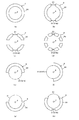
- FIG. 9 is an explanatory view showing a modified example of the protruding rib 3 of FIG.
- the protrusions 30 constituting the protruding rib 3 may be disposed along a circle.
- the projecting rib 3 may be constituted by one protrusion 30, and (b) to (d) in FIG.
- the projecting rib 3 may be comprised by the some protrusion 30.
- FIG. 9 shows in FIG.
- a plurality of openings 31 may be disposed to face each other with the central position of the protruding rib 3 interposed therebetween, as shown in (e) of FIG. And as shown to (f), the one opening part 31 may be provided so that the aperture ratio of the projecting rib 3 may be 50%. As shown to (h) of FIG. 9, one part of the opening part 31 can also be made into the lower side opening part 31E, making the aperture ratio of the projecting rib 3 into 50%.
- FIG. 10 is an explanatory view showing a further modified example of the protruding rib 3 of FIG.
- the protrusions 30 constituting the protruding rib 3 may be disposed along the sides of the square.
- the projecting rib 3 may be configured by one protrusion 30, and in (b) to (d) and (f) to (h) of FIG.
- the projecting rib 3 may be configured by a plurality of protrusions 30 as shown.
- a plurality of openings 31 may be arranged to face each other with the central position of the protruding rib 3 interposed therebetween.
- one opening 31 may be provided such that the opening ratio of the protruding rib 3 is 50%.
- a part of opening 31 can also be made into the lower side opening 31E, making the aperture ratio of the projecting rib 3 into 50%.
- FIG. 11 is an explanatory view showing still another modified example of the protruding rib 3 of FIG.
- the protrusions 30 constituting the protruding rib 3 may be disposed along the sides of a triangle, a rhombus (square), a pentagon and an octagon.
- the protrusions 30 may be disposed along the sides of the polygon having more corners. Even when the protrusions 30 are disposed along the sides of a triangle, a rhombus (square), a pentagon or an octagon as shown in (a) to (e) of FIG. 11, as shown in FIGS. An opening 31 can be provided.
- the inventor made a trial manufacture of the metal wall material 1 as a test material under the following conditions.
- a coated hot-dip Zn-55% Al-plated steel plate a painted hot-dip Zn-6% Al-3% Mg-plated steel plate or a painted hot-dip Al-plated steel plate was used.
- the back substrate 0.2 mm glass fiber paper, 0.2 mm Al vapor-deposited paper, 0.2 mm PE resin film, 0.1 mm Al foil or 0.27 mm painted hot-dip galvanized steel sheet was used.
- the core material 12 a two-component mixed foam resin was used. The mixing ratio of the polyol component and the isocyanate, phenol or nurate component was 1: 1 in weight ratio.
- the back substrate 11 is disposed on the back side of the front substrate 10 so as to close the opening of the main body 100, and a commercially available high pressure injector
- the foamed resin was injected into the space between the main body portion 100 of the front substrate 10 and the back substrate 11.
- the resin foam is kept for 2 minutes in a mold whose temperature is adjusted to 70 ° C. by warm water circulation, then the roofing material is taken out from the mold and allowed to stand for 5 minutes at room temperature 20 ° C. to complete the foaming of the resin.
- the metal plate extending from the lower end of the main body 100 toward the outer side of the main body 100 is cut so that the projecting width of the flange is 5 mm, and the metal plate is formed into a predetermined shape by a bender. It was bent to The dimensions of the final metal wall material 1 were 414 mm ⁇ 910 mm. The final thickness of the wall material was in the range of 3 mm to 8 mm.
- the shape of the protruding rib 3, the presence or absence of the lower opening 31E, the height H of the protrusion 30, the shortest distance L from the central position of the internal region 3a to the protrusion 30, the protrusion 30 The value obtained by dividing the width W of the projection 30 by the height H of the projection 30, the opening ratio (proportion of the opening 31 in the projecting rib 3) is changed, and the following evaluation of (1) wall material weight, (2) The evaluation of depressions at the time of tightening, (3) evaluation of the occurrence of coating film cracks, and (4) evaluation of the ease of flow of rainwater were performed. The results are shown in the following table.
- the shortest distance L is reduced, when the wall material is tightened with a nail or a screw by a metal hammer, a driver or an electric tool, the projection 30 may become a barrier to hinder the tightening operation. Therefore, the shortest distance L is preferably 5 mm or more.
- the protruding rib 3 comprising at least one protrusion 30 disposed along the side of a polygon or disposed along a circle Is provided in the top plate portion 101 of the main body portion 100, and the binding member is driven into the inner region 3a of the protruding rib 3, so that the dent or buckling of the front substrate 10 due to the driving of the binding member is reduced.
- At least one opening 31 communicating the outer region 3b of the protruding rib 3 with the inner region 3a is provided in the protruding rib 3, so that the upper portion of the protruding rib 3 is another metal wall material Even if it is blocked by this, it is possible to secure the flow of air moving in and out of the projecting rib 3. Thereby, even if water such as rainwater intrudes into the inner region 3a of the protruding rib 3, evaporation of the water can be promoted, and the possibility of water remaining in the inner region 3a of the protruding rib 3 is reduced. be able to.
- the at least one opening 31 includes the lower opening 31E located below the protruding rib 3 when the metal wall material 1 is disposed on the wall base, the protruding rib 3 is formed.
- the moisture which has entered the inner region 3a of the second embodiment can escape to the outer region 3b of the projecting rib 3 through the lower opening 31E, and the possibility of the moisture remaining in the inner region 3a of the projecting rib 3 is reduced. Can.
- the ratio (aperture ratio) occupied by the openings 31 in the projecting ribs 3 is 50% or less, it is possible to suppress the deformation of the front substrate 10 due to the impaction of the binding member.
- the height H of the protrusion 30 is 0.2 mm or more, it is possible to suppress the deformation of the front base material 10 due to the driving of the binding member.
- the coating film formed on the surface of the metal plate constituting the top plate portion 101 Cracks can be more reliably avoided.
- the shortest distance from the center position of the inner region 3a to the projection 30 is 5 mm or more and 20 mm or less, it is possible to suppress the deformation of the front substrate 10 due to the driving of the binding member.
- the plate thickness of the metal plate which comprises the front base material 10 is 0.5 mm or less, it can avoid more reliably that the weight of the metal wall material 1 becomes large.
Landscapes
- Engineering & Computer Science (AREA)
- Architecture (AREA)
- Civil Engineering (AREA)
- Structural Engineering (AREA)
- Finishing Walls (AREA)
Abstract
Description
実施の形態.
図1は本発明の実施の形態による金属壁材1を示す正面図であり、図2は図1の金属壁材1を示す背面図であり、図3は図1の線III-IIIに沿う金属壁材1の断面図であり、図4は図1の本体部100の別態様を示す説明図であり、図5は図1の金属壁材1を用いた壁施工構造及び壁施工方法を示す説明図である。
開口率(%)=(開口部に対応する中心角の総和÷360)×100
開口部に対応する中心角とは、図8のように内部領域3aに収まる最も大きな半径を有する円を描くとともに、その円の中心と各開口部31aの内両端とを通る直線を描いた際に、各開口部31aに対応する直線間の角度θ1・・・θnである。図8のように4つの開口部31aが突状リブ3に設けられた態様の場合、開口率(%)={(θ1+θ2+θ3+θ4)÷360}×100と表される。なお、内部領域3aに収まる円とは、突状リブ3の内側に位置する円であって、すべての突部30の縦内壁30aを超えて延在しない円を意味する。また、nは開口部31の数に対応する任意の正数である。後に実施例を挙げて説明するように、突状リブ3の開口率が50%以下であることで、緊結部材の打込みによる表基材10の変形を小さく抑えることができる。
裏基材11のとしては、0.2mmガラス繊維紙、0.2mmAl蒸着紙、0.2mmPE樹脂フィルム、0.1mmAl箔又は0.27mm塗装溶融Znめっき鋼板を使用した。
芯材12としては、2液混合型の発泡樹脂を使用した。ポリオール成分とイソシアネート、フェノールもしくはヌレート成分の混合比率は重量比で1:1とした。

壁材の単重を計測し、施工性から以下の基準により評価した。
○:壁材単重が20N/枚未満
△:壁材単重が20N/枚以上
緊結部材として、市販の山喜産業株式会社製ベストビス(径4.0mmφ×長さ35mm)とインパクトドライバー(株式会社マキタ製TD136D)とを使用して、2枚重ねの壁材を緊結した。緊結の窪みは、緊結した上側の壁材の窪みを隙間ゲージによって測定し、以下の評価基準により評価した。
○:緊結時の窪みが2mm未満
△:緊結時の窪みが2mm以上
突部30を形成するときに塗装鋼板に発生する塗膜クラックを10倍の拡大鏡により目視で観察し、以下の評価基準により評価した。
○:塗膜クラックの発生が認められないか、又は軽微なクラックが認められる
△:著しい塗膜クラックの発生が認められる
壁材を勾配15°に傾斜させ、壁材の上部に1000mLの水道水を流し、突状リブ3の内部領域3aに残る状況を目視により以下の評価基準で評価した。
○:水が淀みなく流れ、内部領域に水がほとんど残っていない
△:水が残っている
Claims (9)
- 金属板を素材とし箱形に形成された本体部を有する表基材と、前記本体部の開口を塞ぐように前記表基材の裏側に配置された裏基材と、前記本体部と前記裏基材との間に充填された芯材とを備え、前記本体部への緊結部材の打込みにより壁下地に緊結される金属壁材であって、
多角形の辺に沿って配設されるか又は円に沿って配設された少なくとも1つの突部からなる突状リブが前記本体部の天板部に設けられており、前記突状リブの内部領域に前記緊結部材が打込まれるように構成されている
ことを特徴とする金属壁材。 - 前記突状リブには、前記突状リブの外部領域と前記内部領域とを連通する少なくとも1つの開口部が設けられている
ことを特徴とする請求項1記載の金属壁材。 - 前記少なくとも1つの開口部は、前記金属壁材が前記壁下地の上に配置された際に前記突状リブの下側に位置する下側開口部を含んでいる
ことを特徴とする請求項2記載の金属壁材。 - 前記突状リブにおいて前記開口部が占める割合が50%以下である
ことを特徴とする請求項2又は請求項3に記載の金属壁材。 - 前記突部の高さが0.2mm以上である
ことを特徴とする請求項1から請求項4までのいずれか一項に記載の金属壁材。 - 前記突部の幅を前記突部の高さで除算した値が3以上である
ことを特徴とする請求項5記載の金属壁材。 - 前記内部領域の中心位置から前記突部までの最短距離が5mm以上かつ20mm以下である
ことを特徴とする請求項1から請求項6までのいずれか一項に記載の金属壁材。 - 前記表基材を構成する前記金属板の板厚が0.5mm以下である
ことを特徴とする請求項1から請求項7までのいずれか一項に記載の金属壁材。 - 金属板を素材とし箱形に形成された本体部を有する表基材と、前記本体部の開口を塞ぐように前記表基材の裏側に配置された裏基材と、前記本体部と前記裏基材との間に充填された芯材とを備え、多角形の辺に沿って配設されるか又は円に沿って配設された少なくとも1つの突部からなる突状リブが前記本体部の天板部に設けられた金属壁材を用いた壁施工方法であって、
前記金属壁材を壁下地の上に配置する工程と、
前記突状リブの内部領域に緊結部材を打ち込んで前記金属壁材を前記壁下地に緊結する工程と
を含む
ことを特徴とする壁施工方法。
Priority Applications (7)
| Application Number | Priority Date | Filing Date | Title |
|---|---|---|---|
| KR1020207006563A KR20200053488A (ko) | 2017-09-28 | 2018-09-21 | 금속 벽재 및 그것을 이용한 벽 시공 방법 |
| EP18862807.7A EP3690164A4 (en) | 2017-09-28 | 2018-09-21 | METAL WALL MATERIAL AND WALL CONSTRUCTION PROCESS WITH IT |
| RU2020114710A RU2020114710A (ru) | 2017-09-28 | 2018-09-21 | Металлический стеновой материал и способ возведения стен c использованием этого материала |
| US16/647,253 US20200256064A1 (en) | 2017-09-28 | 2018-09-21 | Metal wall material and wall construction method using same |
| CN201880062603.0A CN111148884A (zh) | 2017-09-28 | 2018-09-21 | 金属壁材以及使用了该金属壁材的壁施工方法 |
| AU2018343395A AU2018343395A1 (en) | 2017-09-28 | 2018-09-21 | Metal wall material and wall construction method using same |
| PH12020550150A PH12020550150A1 (en) | 2017-09-28 | 2020-03-26 | Metal wall material and wall construction method using same |
Applications Claiming Priority (2)
| Application Number | Priority Date | Filing Date | Title |
|---|---|---|---|
| JP2017188623A JP6981147B2 (ja) | 2017-09-28 | 2017-09-28 | 金属壁材及びそれを用いた壁施工方法 |
| JP2017-188623 | 2017-09-28 |
Publications (1)
| Publication Number | Publication Date |
|---|---|
| WO2019065524A1 true WO2019065524A1 (ja) | 2019-04-04 |
Family
ID=65903118
Family Applications (1)
| Application Number | Title | Priority Date | Filing Date |
|---|---|---|---|
| PCT/JP2018/035136 Ceased WO2019065524A1 (ja) | 2017-09-28 | 2018-09-21 | 金属壁材及びそれを用いた壁施工方法 |
Country Status (10)
| Country | Link |
|---|---|
| US (1) | US20200256064A1 (ja) |
| EP (1) | EP3690164A4 (ja) |
| JP (1) | JP6981147B2 (ja) |
| KR (1) | KR20200053488A (ja) |
| CN (1) | CN111148884A (ja) |
| AU (1) | AU2018343395A1 (ja) |
| PH (1) | PH12020550150A1 (ja) |
| RU (1) | RU2020114710A (ja) |
| TW (1) | TW201932689A (ja) |
| WO (1) | WO2019065524A1 (ja) |
Families Citing this family (3)
| Publication number | Priority date | Publication date | Assignee | Title |
|---|---|---|---|---|
| EA201992465A1 (ru) | 2017-05-23 | 2020-05-08 | Ниппон Стил Ниссин Ко., Лтд. | Металлический кровельный материал и способ выполнения кровли с применением упомянутого материала |
| CN112554396A (zh) * | 2020-12-11 | 2021-03-26 | 李兴 | 一种内外互消式抗风型建筑幕墙 |
| WO2025122742A1 (en) * | 2023-12-05 | 2025-06-12 | GAF Energy LLC | Roofing system for prevention of roofing shingle deformation |
Citations (5)
| Publication number | Priority date | Publication date | Assignee | Title |
|---|---|---|---|---|
| JPS6437826A (en) | 1987-08-04 | 1989-02-08 | Matsushita Electric Industrial Co Ltd | Electrolyte for driving electrolytic capacitor |
| JPH0967901A (ja) * | 1995-08-31 | 1997-03-11 | Furukawa Electric Co Ltd:The | 屋根及び外装用建材 |
| JP2001288854A (ja) * | 2000-04-07 | 2001-10-19 | Mtr Business Corporation:Kk | 屋根材とその製造方法および屋根材の施工方法 |
| JP2008303627A (ja) * | 2007-06-08 | 2008-12-18 | Ig Kogyo Kk | 外壁材の接続構造 |
| JP2017066853A (ja) * | 2015-10-02 | 2017-04-06 | 日新製鋼株式会社 | 金属屋根材及び屋根葺き方法 |
Family Cites Families (11)
| Publication number | Priority date | Publication date | Assignee | Title |
|---|---|---|---|---|
| FR927992A (fr) * | 1946-04-27 | 1947-11-14 | élément en plaque formant matériau pour toitures et terrasses | |
| US4712351A (en) * | 1986-11-10 | 1987-12-15 | The Celotex Corporation | Vinyl siding |
| JP2826334B2 (ja) * | 1989-01-24 | 1998-11-18 | 株式会社アイジー技術研究所 | パネルの目地構造 |
| JPH10238069A (ja) * | 1997-02-25 | 1998-09-08 | Ig Tech Res Inc | 外壁構造 |
| JP2008240321A (ja) * | 2007-03-27 | 2008-10-09 | Ig Kogyo Kk | 屋根材 |
| ES2373894B1 (es) * | 2009-10-08 | 2012-12-17 | Asturiana De Laminados, S.A. | Plaqueta para cubiertas y fachadas y recubrimiento obtenido mediante el uso de dicha plaqueta. |
| US8307599B2 (en) * | 2010-07-12 | 2012-11-13 | Certainteed Corporation | Molded shingles with moisture guards for fasteners and with shingle alignment features |
| CN203008284U (zh) * | 2012-12-27 | 2013-06-19 | 上海合富建筑科技有限公司 | 造型格条墙面板 |
| JP5999824B1 (ja) * | 2015-11-27 | 2016-09-28 | 日新製鋼株式会社 | 金属屋根材並びにそれを用いた屋根葺き構造及び屋根葺き方法 |
| EA201992465A1 (ru) * | 2017-05-23 | 2020-05-08 | Ниппон Стил Ниссин Ко., Лтд. | Металлический кровельный материал и способ выполнения кровли с применением упомянутого материала |
| CN207700591U (zh) * | 2018-01-04 | 2018-08-07 | 郝振欣 | 装饰装修用的墙板 |
-
2017
- 2017-09-28 JP JP2017188623A patent/JP6981147B2/ja not_active Expired - Fee Related
-
2018
- 2018-09-21 WO PCT/JP2018/035136 patent/WO2019065524A1/ja not_active Ceased
- 2018-09-21 EP EP18862807.7A patent/EP3690164A4/en not_active Withdrawn
- 2018-09-21 CN CN201880062603.0A patent/CN111148884A/zh active Pending
- 2018-09-21 AU AU2018343395A patent/AU2018343395A1/en not_active Abandoned
- 2018-09-21 RU RU2020114710A patent/RU2020114710A/ru unknown
- 2018-09-21 KR KR1020207006563A patent/KR20200053488A/ko not_active Ceased
- 2018-09-21 US US16/647,253 patent/US20200256064A1/en not_active Abandoned
- 2018-09-28 TW TW107134376A patent/TW201932689A/zh unknown
-
2020
- 2020-03-26 PH PH12020550150A patent/PH12020550150A1/en unknown
Patent Citations (5)
| Publication number | Priority date | Publication date | Assignee | Title |
|---|---|---|---|---|
| JPS6437826A (en) | 1987-08-04 | 1989-02-08 | Matsushita Electric Industrial Co Ltd | Electrolyte for driving electrolytic capacitor |
| JPH0967901A (ja) * | 1995-08-31 | 1997-03-11 | Furukawa Electric Co Ltd:The | 屋根及び外装用建材 |
| JP2001288854A (ja) * | 2000-04-07 | 2001-10-19 | Mtr Business Corporation:Kk | 屋根材とその製造方法および屋根材の施工方法 |
| JP2008303627A (ja) * | 2007-06-08 | 2008-12-18 | Ig Kogyo Kk | 外壁材の接続構造 |
| JP2017066853A (ja) * | 2015-10-02 | 2017-04-06 | 日新製鋼株式会社 | 金属屋根材及び屋根葺き方法 |
Non-Patent Citations (1)
| Title |
|---|
| See also references of EP3690164A4 |
Also Published As
| Publication number | Publication date |
|---|---|
| AU2018343395A1 (en) | 2020-03-19 |
| RU2020114710A (ru) | 2021-10-28 |
| KR20200053488A (ko) | 2020-05-18 |
| EP3690164A1 (en) | 2020-08-05 |
| EP3690164A4 (en) | 2021-06-09 |
| JP2019065466A (ja) | 2019-04-25 |
| CN111148884A (zh) | 2020-05-12 |
| PH12020550150A1 (en) | 2021-02-08 |
| RU2020114710A3 (ja) | 2021-12-09 |
| JP6981147B2 (ja) | 2021-12-15 |
| TW201932689A (zh) | 2019-08-16 |
| US20200256064A1 (en) | 2020-08-13 |
Similar Documents
| Publication | Publication Date | Title |
|---|---|---|
| KR102323897B1 (ko) | 금속 지붕재 및 그것을 이용한 지붕잇기 방법 | |
| WO2019065524A1 (ja) | 金属壁材及びそれを用いた壁施工方法 | |
| US10233645B2 (en) | Metal roofing member, and roofing structure and roofing method using same | |
| KR102674004B1 (ko) | 금속 지붕재 및 지붕 이음 방법 | |
| US10597874B2 (en) | Metal roofing material, and roofing structure and roofing method using same | |
| JP6378237B2 (ja) | 金属屋根材及びそれを用いた屋根葺き方法 | |
| TW201930700A (zh) | 屋頂的修補方法以及屋頂構造 | |
| KR102107952B1 (ko) | 금속 지붕재 | |
| US10400455B2 (en) | Metal roofing member, production method thereof, roofing structure and roofing method | |
| TWI750179B (zh) | 金屬屋頂構材及使用該金屬屋頂構材之屋頂敷設方法 | |
| JP6545328B2 (ja) | 金属屋根材及びその製造方法並びに屋根葺き構造及び屋根葺き方法 | |
| JP2010275731A (ja) | ラス網および防水シート付ラス網 | |
| JP2017066834A (ja) | 金属屋根材及びそれを用いた屋根葺き方法 | |
| JP2019136800A (ja) | 切断機及びそれを用いた複合建築材の製造方法 | |
| JP3144778U (ja) | 門袖ユニット | |
| WO2019069679A1 (ja) | 金属屋根材の製造方法 | |
| JPS6024820Y2 (ja) | 目地部強化モルタル下地板 | |
| JP2003027656A (ja) | 発泡樹脂製断熱パネル |
Legal Events
| Date | Code | Title | Description |
|---|---|---|---|
| 121 | Ep: the epo has been informed by wipo that ep was designated in this application |
Ref document number: 18862807 Country of ref document: EP Kind code of ref document: A1 |
|
| ENP | Entry into the national phase |
Ref document number: 2018343395 Country of ref document: AU Date of ref document: 20180921 Kind code of ref document: A |
|
| NENP | Non-entry into the national phase |
Ref country code: DE |
|
| ENP | Entry into the national phase |
Ref document number: 2018862807 Country of ref document: EP Effective date: 20200428 |