WO2019065654A1 - プリンタ - Google Patents
プリンタ Download PDFInfo
- Publication number
- WO2019065654A1 WO2019065654A1 PCT/JP2018/035515 JP2018035515W WO2019065654A1 WO 2019065654 A1 WO2019065654 A1 WO 2019065654A1 JP 2018035515 W JP2018035515 W JP 2018035515W WO 2019065654 A1 WO2019065654 A1 WO 2019065654A1
- Authority
- WO
- WIPO (PCT)
- Prior art keywords
- ribbon
- printer
- shaft
- ribbon supply
- printing unit
- Prior art date
- Legal status (The legal status is an assumption and is not a legal conclusion. Google has not performed a legal analysis and makes no representation as to the accuracy of the status listed.)
- Ceased
Links
Images


Classifications
-
- B—PERFORMING OPERATIONS; TRANSPORTING
- B41—PRINTING; LINING MACHINES; TYPEWRITERS; STAMPS
- B41J—TYPEWRITERS; SELECTIVE PRINTING MECHANISMS, i.e. MECHANISMS PRINTING OTHERWISE THAN FROM A FORME; CORRECTION OF TYPOGRAPHICAL ERRORS
- B41J2/00—Typewriters or selective printing mechanisms characterised by the printing or marking process for which they are designed
- B41J2/315—Typewriters or selective printing mechanisms characterised by the printing or marking process for which they are designed characterised by selective application of heat to a heat sensitive printing or impression-transfer material
- B41J2/32—Typewriters or selective printing mechanisms characterised by the printing or marking process for which they are designed characterised by selective application of heat to a heat sensitive printing or impression-transfer material using thermal heads
- B41J2/325—Typewriters or selective printing mechanisms characterised by the printing or marking process for which they are designed characterised by selective application of heat to a heat sensitive printing or impression-transfer material using thermal heads by selective transfer of ink from ink carrier, e.g. from ink ribbon or sheet
-
- B—PERFORMING OPERATIONS; TRANSPORTING
- B41—PRINTING; LINING MACHINES; TYPEWRITERS; STAMPS
- B41J—TYPEWRITERS; SELECTIVE PRINTING MECHANISMS, i.e. MECHANISMS PRINTING OTHERWISE THAN FROM A FORME; CORRECTION OF TYPOGRAPHICAL ERRORS
- B41J17/00—Mechanisms for manipulating page-width impression-transfer material, e.g. carbon paper
- B41J17/22—Supply arrangements for webs of impression-transfer material
- B41J17/24—Webs supplied from reels or spools attached to the machine
-
- B—PERFORMING OPERATIONS; TRANSPORTING
- B41—PRINTING; LINING MACHINES; TYPEWRITERS; STAMPS
- B41J—TYPEWRITERS; SELECTIVE PRINTING MECHANISMS, i.e. MECHANISMS PRINTING OTHERWISE THAN FROM A FORME; CORRECTION OF TYPOGRAPHICAL ERRORS
- B41J3/00—Typewriters or selective printing or marking mechanisms characterised by the purpose for which they are constructed
- B41J3/36—Typewriters or selective printing or marking mechanisms characterised by the purpose for which they are constructed for portability, i.e. hand-held printers or laptop printers
-
- B—PERFORMING OPERATIONS; TRANSPORTING
- B41—PRINTING; LINING MACHINES; TYPEWRITERS; STAMPS
- B41J—TYPEWRITERS; SELECTIVE PRINTING MECHANISMS, i.e. MECHANISMS PRINTING OTHERWISE THAN FROM A FORME; CORRECTION OF TYPOGRAPHICAL ERRORS
- B41J35/00—Other apparatus or arrangements associated with, or incorporated in, ink-ribbon mechanisms
- B41J35/28—Detachable carriers or holders for ink-ribbon mechanisms
-
- B—PERFORMING OPERATIONS; TRANSPORTING
- B41—PRINTING; LINING MACHINES; TYPEWRITERS; STAMPS
- B41J—TYPEWRITERS; SELECTIVE PRINTING MECHANISMS, i.e. MECHANISMS PRINTING OTHERWISE THAN FROM A FORME; CORRECTION OF TYPOGRAPHICAL ERRORS
- B41J2202/00—Embodiments of or processes related to ink-jet or thermal heads
- B41J2202/30—Embodiments of or processes related to thermal heads
- B41J2202/31—Thermal printer with head or platen movable
-
- B—PERFORMING OPERATIONS; TRANSPORTING
- B41—PRINTING; LINING MACHINES; TYPEWRITERS; STAMPS
- B41J—TYPEWRITERS; SELECTIVE PRINTING MECHANISMS, i.e. MECHANISMS PRINTING OTHERWISE THAN FROM A FORME; CORRECTION OF TYPOGRAPHICAL ERRORS
- B41J35/00—Other apparatus or arrangements associated with, or incorporated in, ink-ribbon mechanisms
- B41J35/04—Ink-ribbon guides
- B41J35/08—Ink-ribbon guides with tensioning arrangements
Definitions
- the present invention relates to a printer.
- JP2009-179010A includes a ribbon supply shaft for holding the ink ribbon supplied to the printing section in a roll, and a ribbon winding shaft for winding the used ink ribbon, and heats the ink ribbon to form the ink ribbon.
- a thermal transfer printer has been disclosed that transfers ink to a print medium for printing.
- the present invention has been made in view of such technical problems, and an object of the present invention is to make it possible to efficiently perform an ink ribbon replacement operation.
- a printer including: a printing unit for printing on a printing medium; a ribbon supply shaft for holding an ink ribbon supplied to the printing unit; and winding up the used ink ribbon A ribbon take-up shaft, and the ribbon supply shaft is provided movably between a ribbon supply position for supplying the ink ribbon to the printing unit and a ribbon replacement position detachable from the printer; A printer is provided, which rotates in a winding direction of the ink ribbon while moving from the ribbon replacement position to the ribbon supply position.
- the ribbon supply axis when the ribbon supply axis is changed from the ribbon replacement position to the ribbon supply position, the ribbon supply axis is automatically rotated to wind the ink ribbon. Therefore, there is no need to rotate the ribbon supply shaft or the ribbon take-up shaft to eliminate slack in the ink ribbon, and the ink ribbon can be replaced efficiently.
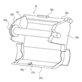
- FIG. 1 is a perspective view of a printer according to an embodiment of the present invention.
- FIG. 2 is a schematic block diagram of a printer according to the embodiment of the present invention.
- FIG. 3 is a perspective view of the partition member and the ribbon supply shaft.
- FIG. 4 is a view showing a state in which the cover is opened.
- FIG. 5 is a view showing a state where the ribbon supply axis is in the ribbon replacement position.
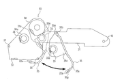
- FIG. 6 is a diagram for explaining the printing unit.
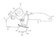
- FIG. 7 is a view for explaining how the partitioning member is moved from the open position to the closed position.
- FIG. 8 is a view for explaining a modification of the printing unit.
- the printer 100 is a thermal transfer type printer that performs printing by heating the ink ribbon R to transfer the ink of the ink ribbon R onto the print medium M.
- the print medium M is, for example, a label continuum in which a plurality of labels are temporarily and successively attached to a band-shaped backing sheet.
- the printer 100 includes a housing 10 and a cover 11 that covers the opening of the housing 10.
- the print medium M is held by the medium supply shaft 12 in a rolled state.
- a pasteless label or a fanfold type medium can be used as the print medium M.
- the cover 11 has an end on one end side pivotally supported by a support shaft 13 provided on the housing 10.
- the cover 11 can be switched between an open state (see FIG. 4) of opening the opening of the housing 10 and a closed state (see FIG. 2) of closing by pivoting the support shaft 13 as a fulcrum. .
- the housing 10 is provided with a lock mechanism (not shown) for keeping the cover 11 in the closed state.
- the lock mechanism is released by operating the lever 14 shown in FIG.
- a discharge port 16 is formed where the print medium M printed by the print unit 15 shown in FIG.
- the cutter 17 facing the discharge port 16 is attached to the cover 11 of the present embodiment. Thereby, the printed print medium M discharged from the discharge port 16 can be cut. Note that various other units can be attached to the cover 11 in place of the cutter 17.
- the cover 11 is provided with an operation unit 19 for operating the printer 100.
- the operation unit 19 includes various operation buttons, a display, a short distance wireless communication module, an LED, and the like.
- the display may be a touch panel.
- a printing unit 30 for printing on the printing medium M, a controller 40 for controlling the operation of the printer 100, and the like are accommodated.
- the printing unit 30 includes a main body 31 whose one end is pivotally supported by the support shaft 13 and a thermal head 32 attached to the main body 31.
- the thermal head 32 and the platen roller 20 provided on the housing 10 constitute a printing unit 15 that prints on the printing medium M.
- the printing unit 30 further includes a ribbon supply shaft 33 for holding the ink ribbon R supplied to the printing unit 15 in a roll, a ribbon winding shaft 34 for winding the used ink ribbon R, and the ink ribbon R and printing.
- a guide shaft 37 which defines a transport path of The ribbon supply shaft 33 is detachably attached to the partition member 35.
- the ink ribbon R of the present embodiment is a front-wound link ribbon whose surface on which the ink is applied is on the outside.
- the print medium M is supplied from the medium supply shaft 12 to the print unit 15 and is nipped between the thermal head 32 and the platen roller 20 together with the ink ribbon R.
- the heating elements of the thermal head 32 When the heating elements of the thermal head 32 are energized while the printing medium M and the ink ribbon R are held between the thermal head 32 and the platen roller 20, the ink of the ink ribbon R is printed by the heat of the heating elements. The image is transferred to the medium M, and printing on the printing medium M is performed.
- the platen roller 20 When the platen roller 20 is rotated forward by a platen drive motor (not shown), the print medium M and the ink ribbon R are transported to the downstream side in the transport direction, and the print medium M is discharged from the discharge port 16 to the outside of the printer 100. Exhausted.
- the partition member 35 supports the base portion 35a, the shaft portion 35b provided on one end side of the base portion 35a, and the ribbon supply shaft 33 in parallel with the shaft portion 35b and rotatably supported. It has the parts 35c and 35d, and the engaging part 35e formed in the center part of the axial part 35b.
- the partition member 35 is swingably supported by the main body 31 by the shaft 35 b.
- the engaging portion 35e is configured to engage with the engaged portion 11a provided on the cover 11 as shown in FIG.
- the ribbon supply shaft 33 is accommodated in the main body portion 31.
- the ribbon supply shaft 33 is at the ribbon supply position for supplying the ink ribbon R to the printing unit 15.
- the partition member 35 is maintained at the closed position where the ribbon supply shaft 33 is at the ribbon supply position by the engagement of the engaging portion 35e and the engaged portion 11a.
- the printing unit 30 and the cover 11 are coupled.
- the cover 11 When printing is performed by the printer 100, the cover 11 is closed, and the engaging portion 35e of the partition member 35 and the engaged portion 11a of the cover 11 are engaged.
- the printing unit 30 is swung integrally with the cover 11, and as shown in FIG. 4, the opening of the case 10 is opened.
- the roll-shaped ink ribbon R held by the ribbon supply shaft 33 and the ribbon supply shaft 33 moves relative to the ribbon winding shaft 34, and the printing medium M Exposed to the outlet 16 side.
- the ribbon take-up shaft 34 is attached to the main body 31 and can not move relative to the printing unit 30.
- the ribbon supply shaft 33 is at the ribbon replacement position where it can be detached from the printer 100, and the ink ribbon R can be replaced.
- the ribbon supply shaft 33 is movable relative to the ribbon take-up shaft 34, and when replacing the ink ribbon R, the ribbon replacement position can be easily performed.
- the ribbon supply shaft 33 can be moved.
- the ribbon supply shaft 33 is exposed on the side of the discharge port 16 of the print medium M, that is, on the side where the user works. According to this, the workability can be further improved.
- the engagement between the engaging portion 35e and the engaged portion 11a can be achieved by elastically deforming the engaging portion 35e and the engaged portion 11a when the partition member 35 is swung toward the housing 10 with a torque equal to or greater than a predetermined torque. Is released.
- the printing unit 30 itself also swings to the predetermined position toward the housing 10 by releasing the engagement between the engaging portion 35e and the engaged portion 11a.
- the predetermined position is a position where a rocking restriction portion (not shown) provided in the vicinity of the support shaft 13 in the housing 10 abuts on the main body portion 31.
- the rocking restriction portion When positioning the printing unit 30 by the rocking restriction portion, the rocking restriction portion is elastically deformed when the printing unit 30 is rocked toward the housing 10 with a torque equal to or more than a predetermined torque, and the main body portion 31 is Get over and get rid of it.
- the base portion 35 a of the partition member 35 extends to a position facing the reflection sensor 21 provided in the housing 10.
- the transport path of the print medium M is formed between the reflection sensor 21 and the portion of the partition member 35 facing the reflection sensor 21.
- the reflection sensor 21 is a sensor that detects an eye mark printed in advance at a predetermined interval on the surface of the print medium M opposite to the surface on which printing is performed. Thereby, the position in the conveyance direction of the print medium M can be detected.
- the partition member 35 guides the print medium M, whereby the print medium M is stably transported within a predetermined distance from the reflection sensor 21. Thereby, the detection accuracy of the reflection sensor 21 can be improved.
- the partition member 35 automatically guides the print medium M.
- the print medium M is guided by the partition member 35, there is no need to additionally provide a guide member for conveying the print medium M within a certain distance from the reflection sensor 21. The operation of inserting the print medium M is also unnecessary.
- the printer 100 further includes a transmission sensor 22 that detects the position of the print medium M in the transport direction.
- the transmission sensor 22 receives a light emitting unit 22a as a light emitting unit that emits a predetermined light, and a light receiving unit that receives light emitted from the light emitting unit 22a and outputs an electric signal corresponding to the intensity of the received light. And a unit 22b.
- the print medium M is a label continuum in which a plurality of labels are temporarily attached to a band-like backing at a predetermined interval, only a part of the backing is present between two adjacent labels.
- the transmitted amount of light emitted from the light emitting unit 22a is different between the portion where the label is present and the portion where only the mount is present, so the intensity of the light received by the light receiving unit 22b changes.
- the transmission sensor 22 can detect the position of the print medium M in the transport direction.
- the light emitting unit 22a is provided on the side opposite to the conveyance path of the printing medium M in the base 35a, that is, on the upper surface side of the base 35a. Further, in the base portion 35a, a through hole 35g through which light emitted from the light emitting unit 22a is formed is formed. On the other hand, as shown in FIG. 2, the light receiving unit 22 b is provided on the side of the housing 10 across the conveyance path.
- the work of setting the print medium M in the printer 100 is performed in a state where the printing unit 30 is in the non-printing position and the opening of the housing 10 is opened.
- the print medium M can be set in the printer 100 with the light emission unit 22a and the light reception unit 22b being largely open, the work of setting the print medium M in the printer 100 can be easily performed. Can.
- the positions of the light emitting unit 22a and the light receiving unit 22b may be interchanged.
- the printer 100 operates either the reflection sensor 21 or the transmission sensor 22 according to the mode of the print medium M to be used to detect the position of the print medium M in the transport direction.
- the printer 100 detects the position of the print medium M by the transmission sensor 22.
- the controller 40 includes a microprocessor, a storage device such as a ROM or a RAM, an input / output interface, a bus connecting these, and the like. Print data from an external computer, a signal from the reflection sensor 21, a signal from the transmission sensor 22 and the like are input to the controller 40 via the input / output interface.
- the controller 40 causes the microprocessor to execute a printing control program stored in the storage device, and controls the energization of the heating elements of the thermal head 32, the energization of the platen drive motor, and the like.
- the ribbon supply shaft 33 has a gear 33a formed on one end side.
- the printing unit 30 includes a gear 38 meshing with the gear 33 a in a state where the ribbon supply shaft 33 is at the ribbon supply position (two-dot chain line).
- the ribbon supply shaft 33 is driven via a gear 38 by a supply shaft drive motor (not shown).
- the ribbon winding shaft 34 has a gear 34a formed on one end side.
- the ribbon take-up shaft 34 is driven by a take-up shaft drive motor (not shown) via a gear (not shown).
- the rotation of the ribbon supply shaft 33 and the ribbon take-up shaft 34 is controlled by the controller 40 in synchronization with the rotation of the platen roller 20.
- the ribbon supply shaft 33 and the ribbon take-up shaft 34 may be driven by one drive motor.
- the printing unit 30 includes the partition member 35 whose one end side is swingably supported by the main body 31 by the shaft 35 b. Further, the ribbon supply shaft 33 is attached to the partition member 35.
- the ribbon supply shaft 33 becomes the ribbon supply position (two-dot chain line) for supplying the ink ribbon R to the printing unit 15
- the ribbon supply shaft 33 is in the ribbon replacement position (solid line) that can be attached to and detached from the printer 100.
- the partition member 35 is provided with a lock mechanism (not shown) for holding the ribbon supply shaft 33. The ribbon supply shaft 33 can be removed from the printer 100 by releasing the lock by the lock mechanism at the ribbon replacement position.
- a rack 31 a is provided in the main body portion 31.
- the rack 31a meshes with the gear 33a while the partition member 35 moves from the open position to the closed position, and rotates the ribbon supply shaft 33 in the direction in which the ink ribbon R is wound.
- the ribbon supply shaft 33 automatically rolls in the direction to wind the ink ribbon R. Is rotated to wind up the ink ribbon R, and the slack of the ink ribbon R is removed.
- the replacement operation of the ink ribbon R can be efficiently performed. Further, since the slack of the ink ribbon R is eliminated, it is possible to prevent the occurrence of the printing failure due to the slack of the ink ribbon R.
- the meshing between the gear 33a and the rack 31a is released immediately before the ribbon supply shaft 33 reaches the ribbon supply position. That is, the rack 31a does not mesh with the gear 33a when the ribbon supply shaft 33 is in the ribbon supply position. Therefore, the rack 31a does not inhibit the rotation of the ribbon supply shaft 33 at the time of printing.
- the printer 100 includes the printing unit 15 for printing on the printing medium M, the ribbon supply shaft 33 for holding the ink ribbon R supplied to the printing unit 15, and the used ink ribbon And the ribbon supply shaft 33 moves between a ribbon supply position for supplying the ink ribbon R to the printing unit 15 and a ribbon replacement position that can be attached to and detached from the printer 100. It is freely provided, and rotates in the direction in which the ink ribbon R is wound up while moving from the ribbon replacement position to the ribbon supply position.
- the ribbon supply shaft 33 is provided with a gear 33a
- the printer 100 includes a rack 31a that engages with the gear 33a while the ribbon supply shaft 33 moves from the ribbon replacement position to the ribbon supply position.
- the ribbon supply shaft 33 when the ribbon supply shaft 33 is changed from the ribbon replacement position to the ribbon supply position, the ribbon supply shaft 33 is automatically rotated to wind the ink ribbon R. Therefore, there is no need to rotate the ribbon supply shaft 33 or the ribbon take-up shaft 34 in order to eliminate the slack of the ink ribbon R, and the ink ribbon R can be replaced efficiently.
- the rack 31a does not mesh with the gear 33a when the ribbon supply shaft 33 is in the ribbon supply position.
- the rack 31a does not inhibit the rotation of the ribbon supply shaft 33 at the time of printing.
- the printer 100 is provided swingably, and includes a partition member 35 that partitions the ink ribbon R and the print medium M, and the ribbon supply shaft 33 is attached to the partition member 35.
- the ribbon supply shaft 33 when replacing the ink ribbon R, the ribbon supply shaft 33 can be moved to the ribbon replacement position where the operation can be easily performed.
- the printer 100 is provided with a printing unit 30 which is swingably provided and has a thermal head 32 constituting the printing unit 15, and the ribbon supply shaft 33, the ribbon winding shaft 34, and the partition member 35 are the printing unit 30.
- the ribbon winding shaft 34 is immovable relative to the printing unit 30.
- the ribbon take-up shaft 34 does not move with respect to the printing unit 30, when the ribbon supply shaft 33 is at the ribbon supply position and the ink ribbon R is taken up, the slack of the ink ribbon R can be eliminated efficiently. .
- the printer 100 includes a housing 10 and a cover 11 that covers the opening of the housing 10, and the partitioning member 35 is an engaging portion 35e that engages with the engaged portion 11a provided on the cover 11.
- the partition member 35 is maintained at the closing position where the ribbon supply shaft 33 is at the ribbon supply position, and the printing unit 30 and the cover 11 are Combined.
- the printing unit 30 integrally swings with the cover 11. Therefore, when performing maintenance of the setting of the printing medium M and each part in the housing
- the ribbon supply shaft 33 attached to the partition member 35 moves relative to the ribbon winding shaft 34.
- the ribbon supply shaft 33 may be moved by providing the slide mechanism 56 for sliding the partition member 55.
- the printing unit 30 may function as a cover without the cover 11.
- the engaged portion that engages with the engaging portion 35 e of the partition member 35 is provided on the main body portion 31 or the like of the printing unit 30.
Landscapes
- Impression-Transfer Materials And Handling Thereof (AREA)
- Printers Characterized By Their Purpose (AREA)
- Electronic Switches (AREA)
Abstract
プリンタは、印字媒体に印字を行う印字部と、印字部に供給されるインクリボンを保持するリボン供給軸と、使用済のインクリボンを巻き取るリボン巻取軸と、を備え、リボン供給軸は、インクリボンを印字部に供給するリボン供給位置と、プリンタに着脱可能なリボン交換位置と、の間で移動自在に設けられ、リボン交換位置からリボン供給位置に移動する途中で、インクリボンを巻き取る方向に回転する。
Description
本発明は、プリンタに関する。
JP2009-179010Aには、印字部に供給されるインクリボンをロール状に保持するリボン供給軸と、使用済のインクリボンを巻き取るリボン巻取軸と、を備え、インクリボンを熱してインクリボンのインクを印字媒体に転写して印字する熱転写方式のプリンタが開示されている。
上記のプリンタでは、インクリボンの交換を行った際は、リボン供給軸或いはリボン巻取軸を回転させてインクリボンの弛みを解消する必要がある。このため、インクリボンの交換作業が煩雑なものとなっていた。
本発明は、このような技術的課題に鑑みてなされたもので、インクリボンの交換作業を効率よく行うことができるようにすることを目的とする。
本発明のある態様によれば、プリンタであって、印字媒体に印字を行う印字部と、前記印字部に供給されるインクリボンを保持するリボン供給軸と、使用済の前記インクリボンを巻き取るリボン巻取軸と、を備え、前記リボン供給軸は、前記インクリボンを前記印字部に供給するリボン供給位置と、前記プリンタに着脱可能なリボン交換位置と、の間で移動自在に設けられ、前記リボン交換位置から前記リボン供給位置に移動する途中で、前記インクリボンを巻き取る方向に回転する、プリンタが提供される。
これによれば、リボン供給軸をリボン交換位置からリボン供給位置にすると、リボン供給軸が自動的に回転してインクリボンを巻き取る。よって、インクリボンの弛みを解消するためにリボン供給軸或いはリボン巻取軸を回転させる作業を行う必要がなく、インクリボンの交換作業を効率よく行うことができる。
以下、添付図面を参照しながら本発明の実施形態に係るプリンタ100について説明する。
プリンタ100は、インクリボンRを熱してインクリボンRのインクを印字媒体Mに転写することで印字を行う熱転写方式のプリンタである。印字媒体Mは、例えば、帯状の台紙に複数のラベルが連続して仮着されたラベル連続体である。
プリンタ100は、図1、図2に示すように、筐体10と、筐体10の開口部を覆うカバー11と、を備える。
印字媒体Mは、図2に示すように、ロール状に巻き回された状態で媒体供給軸12に保持される。なお、印字媒体Mとして、台紙なしラベルやファンフォールド型媒体を使用することもできる。
カバー11は、筐体10に設けられた支持軸13により一端側の端部が揺動自在に支持される。カバー11は、支持軸13を支点として揺動させることで、筐体10の開口部を開放する開放状態(図4参照)と、閉止する閉止状態(図2参照)と、を切り替えることができる。
筐体10には、カバー11を閉止状態に維持するロック機構(図示せず)が設けられる。ロック機構は、図1に示すレバー14を操作することで解除される。
カバー11の他端側の端部と筐体10との間には、図2に示す印字部15で印字された印字媒体Mがプリンタ100から排出される排出口16が形成される。
本実施形態のカバー11には、排出口16に臨むカッタ17が取り付けられる。これにより、排出口16から排出された印字済の印字媒体Mを切断することができる。なお、カバー11には、カッタ17に代えて他の様々なユニットを取り付けることができる。
また、カバー11には、プリンタ100を操作するための操作ユニット19が設けられる。操作ユニット19は、各種操作ボタン、ディスプレイ、近距離無線通信モジュール、LED等を有する。ディスプレイは、タッチパネルであってもよい。
プリンタ100の内部には、印字媒体Mに印字を行うための印字ユニット30、プリンタ100の動作を制御するコントローラ40等が収容される。
印字ユニット30は、一端側が支持軸13に揺動自在に支持される本体部31と、本体部31に取り付けられるサーマルヘッド32と、を備える。
サーマルヘッド32は、筐体10側に設けられたプラテンローラ20と共に、印字媒体Mに印字を行う印字部15を構成する。
また、印字ユニット30は、印字部15に供給されるインクリボンRをロール状に保持するリボン供給軸33と、使用済のインクリボンRを巻き取るリボン巻取軸34と、インクリボンRと印字媒体Mとの間を仕切る仕切部材35と、リボン供給軸33から印字部15へのインクリボンRの搬送路を規定するガイド軸36と、印字部15からリボン巻取軸34へのインクリボンRの搬送路を規定するガイド軸37と、を備える。リボン供給軸33は、仕切部材35に着脱可能に取り付けられている。なお、本実施形態のインクリボンRは、インクが塗布された面が外側になる表巻きのリンクリボンである。
印字媒体Mは、媒体供給軸12から印字部15に供給され、サーマルヘッド32とプラテンローラ20との間にインクリボンRと共に挟持される。
印字媒体M及びインクリボンRがサーマルヘッド32とプラテンローラ20との間に挟持された状態でサーマルヘッド32の発熱素子への通電が行われると、発熱素子の熱によってインクリボンRのインクが印字媒体Mに転写され、印字媒体Mへの印字が行われる。
また、プラテン駆動モータ(図示せず)によってプラテンローラ20を正回転させると、印字媒体M及びインクリボンRが搬送方向下流側へと搬送されて印字媒体Mが排出口16からプリンタ100の外部に排出される。
仕切部材35は、図3に示すように、ベース部35aと、ベース部35aの一端側に設けられた軸部35bと、リボン供給軸33を軸部35bと平行且つ回動自在に支持する支持部35c、35dと、軸部35bの中央部に形成された係合部35eと、を有する。
仕切部材35は、軸部35bにより本体部31に揺動自在に支持される。
係合部35eは、図2に示すように、カバー11に設けられた被係合部11aと係合するように構成される。仕切部材35を係合部35eが被係合部11aと係合する位置(閉止位置)にすると、リボン供給軸33が本体部31内に収容される。これにより、リボン供給軸33が、印字部15にインクリボンRを供給するリボン供給位置になる。
このように、係合部35eと被係合部11aとが係合することで、リボン供給軸33がリボン供給位置になる閉止位置に仕切部材35が維持される。また、印字ユニット30とカバー11とが結合された状態となる。
プリンタ100による印字を行う際は、カバー11は閉止状態とされ、且つ、仕切部材35の係合部35eとカバー11の被係合部11aとが係合した状態とされる。
よって、カバー11を閉止状態から開放状態にすると、印字ユニット30がカバー11と一体となって揺動し、図4に示すように、筐体10の開口部が開放される。
これにより、プリンタ100への印字媒体Mのセットや筐体10内の各部のメンテナンスを行うことができる。
さらに、図4に示す状態から係合部35eと被係合部11aとの係合を解除して仕切部材35を筐体10側に向けて揺動させると、仕切部材35が図5に示す開放位置になる。
仕切部材35が開放位置になるのに伴い、リボン供給軸33及びリボン供給軸33に保持されたロール状のインクリボンRがリボン巻取軸34に対して相対的に移動し、印字媒体Mの排出口16側に露出する。なお、リボン巻取軸34は本体部31に取り付けられており、印字ユニット30に対して移動不能である。
これにより、リボン供給軸33がプリンタ100から着脱可能なリボン交換位置となり、インクリボンRの交換作業を行うことができる。
このように、本実施形態では、リボン供給軸33は、リボン巻取軸34に対して相対移動自在とされ、インクリボンRの交換を行う際に、作業を容易に行うことができるリボン交換位置にリボン供給軸33を移動させることができる。
また、リボン供給軸33は、印字媒体Mの排出口16側、すなわち、ユーザの作業位置側に露出する。これによれば、作業性をより向上させることができる。
また、リボン供給軸33がリボン交換位置になった状態では、図5に示すように、リボン供給軸33からリボン巻取軸34までのインクリボンRの搬送路が全て露出する。よって、リボン供給軸33からリボン巻取軸34までインクリボンRを掛け渡す作業も容易になる。
係合部35eと被係合部11aとの係合は、仕切部材35を所定トルク以上のトルクで筐体10側に揺動させると、係合部35e及び被係合部11aが弾性変形して解除される。
なお、係合部35eと被係合部11aとの係合が解除されることで、印字ユニット30自体も、筐体10側に向けて所定の位置まで揺動する。所定の位置は、筐体10における支持軸13の近傍に設けられた揺動規制部(図示せず)と本体部31とが当接する位置である。
揺動規制部による印字ユニット30の位置決めは、印字ユニット30を所定トルク以上のトルクで筐体10側に揺動させると、揺動規制部が弾性変形して本体部31が揺動規制部を乗り越えて解除される。
また、図2に示すように、仕切部材35のベース部35aは、筐体10に設けられた反射センサ21と対向する位置まで延伸している。これにより、反射センサ21と仕切部材35における反射センサ21と対向する部位との間に、印字媒体Mの搬送路が形成される。
反射センサ21は、印字媒体Mの印字が施される面とは反対側の面に所定の間隔で予め印刷されているアイマークを検出するセンサである。これにより、印字媒体Mの搬送方向における位置を検出することができる。
本実施形態では、仕切部材35が印字媒体Mをガイドすることで、反射センサ21から一定の距離内で印字媒体Mが安定して搬送される。これにより、反射センサ21の検出精度を向上させることができる。
なお、プリンタ100を印字可能な状態、つまり、図2に示す状態にすると、自動的に仕切部材35が印字媒体Mをガイドする状態となる。
このように、仕切部材35によって印字媒体Mがガイドされるので、反射センサ21から一定の距離内で印字媒体Mが搬送されるようにするためのガイド部材を別途設ける必要がなく、ガイド部材に印字媒体Mを挿通する作業も不要となる。
また、プリンタ100は、搬送方向における印字媒体Mの位置を検出する透過センサ22を備える。
透過センサ22は、所定の光を出射する発光部としての発光ユニット22aと、発光ユニット22aから出射された光を受光し、受光した光の強度に対応する電気信号を出力する受光部としての受光ユニット22bと、を有するセンサである。
例えば、印字媒体Mが、帯状の台紙に複数のラベルが所定の間隔で連続して仮着されたラベル連続体である場合は、隣り合う2つのラベルの間には、台紙のみの部分が存在する。
ラベルが存在する部分と台紙のみの部分とでは、発光ユニット22aから出射された光の透過量が異なるので、受光ユニット22bが受光する光の強度が変化する。これにより、透過センサ22は、搬送方向における印字媒体Mの位置を検出することができる。
本実施形態では、図2、図3に示すように、発光ユニット22aは、ベース部35aにおける印字媒体Mの搬送路とは反対側、つまり、ベース部35aの上面側に設けられる。また、ベース部35aには、発光ユニット22aから出射された光を通す貫通孔35gが形成されている。一方、受光ユニット22bは、図2に示すように、搬送路を挟んで筐体10側に設けられる。
上述したように、印字媒体Mをプリンタ100にセットする作業は、印字ユニット30を非印字位置にして筐体10の開口部を開放した状態で行われる。
つまり、本実施形態では、発光ユニット22aと受光ユニット22bとの間が大きく開放された状態で印字媒体Mをプリンタ100にセットできるので、印字媒体Mをプリンタ100にセットする作業を容易に行うことができる。なお、発光ユニット22aと受光ユニット22bとの位置を入れ替えてもよい。
プリンタ100は、使用する印字媒体Mの態様に応じて、反射センサ21と透過センサ22とのいずれか作動させて搬送方向における印字媒体Mの位置を検出するようになっている。
例えば、アイマークが設けられていない印字媒体Mを使用する場合は、プリンタ100は、透過センサ22によって印字媒体Mの位置を検出する。
コントローラ40は、マイクロプロセッサ、ROMやRAM等の記憶装置、入出力インターフェース、これらを接続するバス等で構成される。コントローラ40には、入出力インターフェースを介して、外部コンピュータからの印字データ、反射センサ21からの信号、透過センサ22からの信号等が入力される。
コントローラ40は、記憶装置に格納されている印字制御プログラムをマイクロプロセッサによって実行し、サーマルヘッド32の発熱素子への通電、プラテン駆動モータへの通電等を制御する。
続いて、印字ユニット30について、主に図6、図7を参照して詳しく説明する。なお、図6、図7は、理解を容易にするためにインクリボンRを省略して記載している。
図3、図6に示すように、リボン供給軸33は、一端側に形成されたギヤ33aを有する。
また、図6に示すように、印字ユニット30は、リボン供給軸33がリボン供給位置にある状態(二点鎖線)で、ギヤ33aと噛合うギヤ38を備える。リボン供給軸33は、ギヤ38を介して供給軸駆動モータ(図示せず)により駆動される。
また、図6に示すように、リボン巻取軸34は、一端側に形成されたギヤ34aを有する。リボン巻取軸34は、ギヤ(図示せず)を介して巻取軸駆動モータ(図示せず)により駆動される。
リボン供給軸33及びリボン巻取軸34の回転は、プラテンローラ20の回転と同期するようにコントローラ40によって制御される。なお、リボン供給軸33及びリボン巻取軸34が1つの駆動モータにより駆動されるようにしてもよい。
上述したように、印字ユニット30は、軸部35bにより一端側が本体部31に揺動自在に支持される仕切部材35を備える。また、リボン供給軸33は、仕切部材35に取り付けられる。
これにより、図6に示すように、仕切部材35を閉止位置(二点鎖線)にすると、リボン供給軸33が、印字部15にインクリボンRを供給するリボン供給位置(二点鎖線)となり、開放位置(実線)にすると、リボン供給軸33が、プリンタ100に着脱可能なリボン交換位置(実線)となる。なお、仕切部材35には、リボン供給軸33を保持するためのロック機構(図示せず)が設けられる。リボン供給軸33は、リボン交換位置においてロック機構によるロックを解除することで、プリンタ100から取り外すことができる。
また、本体部31には、図6、図7に示すように、ラック31aが設けられる。
ラック31aは、図7に示すように、仕切部材35が開放位置から閉止位置に移動する途中でギヤ33aと噛合い、インクリボンRを巻き取る方向にリボン供給軸33を回転させる。
インクリボンRの交換を行った場合等においては、図5に示すように、インクリボンRに弛みが生じる場合がある。インクリボンRに弛みが生じた場合は、リボン供給軸33或いはリボン巻取軸34を回転させてインクリボンRの弛みを除去する作業が必要となる。
これに対して、本実施形態では、仕切部材35を開放位置から閉止位置にしてリボン供給軸33をリボン交換位置からリボン供給位置にすると、リボン供給軸33がインクリボンRを巻き取る方向に自動的に回転してインクリボンRを巻き取り、インクリボンRの弛みが除去される。
これによれば、インクリボンRの弛みを解消するためにリボン供給軸33或いはリボン巻取軸34を回転させる作業を行う必要が無いので、インクリボンRの交換作業を効率よく行うことができる。また、インクリボンRの弛みが解消されるので、インクリボンRの弛みに起因する印字不良の発生を防止できる。
なお、ギヤ33aとラック31aとの噛合いは、リボン供給軸33がリボン供給位置になる直前で解除される。つまり、ラック31aは、リボン供給軸33がリボン供給位置にある状態では、ギヤ33aと噛み合わないようになっている。よって、印字の際にラック31aがリボン供給軸33の回転を阻害することがない。
また、ギヤ33aとラック31aとの噛合いが解除されてすぐにギヤ33aとギヤ38とが噛み合うので、ギヤ33aとラック31aとの噛合いが解除されてからギヤ33aとギヤ38とが噛み合うまでの間にリボン供給軸33がインクリボンRを印字部15に供給する方向に回転してしまうことを抑制できる。
以上述べたように、本実施形態のプリンタ100は、印字媒体Mに印字を行う印字部15と、印字部15に供給されるインクリボンRを保持するリボン供給軸33と、使用済のインクリボンRを巻き取るリボン巻取軸34と、を備え、リボン供給軸33は、インクリボンRを印字部15に供給するリボン供給位置と、プリンタ100に着脱可能なリボン交換位置と、の間で移動自在に設けられ、リボン交換位置からリボン供給位置に移動する途中で、インクリボンRを巻き取る方向に回転する。
具体的には、リボン供給軸33にはギヤ33aが設けられ、プリンタ100は、リボン供給軸33がリボン交換位置からリボン供給位置に移動する途中でギヤ33aと噛み合うラック31aを備える。
これによれば、リボン供給軸33をリボン交換位置からリボン供給位置にすると、リボン供給軸33が自動的に回転してインクリボンRを巻き取る。よって、インクリボンRの弛みを解消するためにリボン供給軸33或いはリボン巻取軸34を回転させる作業を行う必要がなく、インクリボンRの交換作業を効率よく行うことができる。
また、ラック31aは、リボン供給軸33がリボン供給位置にある状態では、ギヤ33aと噛み合わない。
よって、印字の際にラック31aがリボン供給軸33の回転を阻害することがない。
また、プリンタ100は、揺動自在に設けられ、インクリボンRと印字媒体Mとの間を仕切る仕切部材35を備え、リボン供給軸33は、仕切部材35に取り付けられる。
これによれば、インクリボンRの交換を行う際に、作業を容易に行うことができるリボン交換位置にリボン供給軸33を移動させることができる。
また、プリンタ100は、揺動自在に設けられ、印字部15を構成するサーマルヘッド32を有する印字ユニット30を備え、リボン供給軸33、リボン巻取軸34、及び仕切部材35は、印字ユニット30に設けられ、リボン巻取軸34は、印字ユニット30に対して移動不能となっている。
これによれば、リボン巻取軸34が印字ユニット30に対して移動しないので、リボン供給軸33をリボン供給位置にしてインクリボンRを巻き取ると、インクリボンRの弛みを効率的に解消できる。
また、プリンタ100は、筐体10と、筐体10の開口部を覆うカバー11と、を備え、仕切部材35は、カバー11に設けられた被係合部11aと係合する係合部35eを有し、係合部35eと被係合部11aとが係合すると、リボン供給軸33がリボン供給位置になる閉止位置に仕切部材35が維持されると共に、印字ユニット30とカバー11とが結合される。
これによれば、カバー11を閉止状態から開放状態にすると、印字ユニット30がカバー11と一体となって揺動する。よって、印字媒体Mのセットや筐体10内の各部のメンテナンスを行う際に、カバー11と印字ユニット30とを個別に開く必要がなく、作業を効率よく行うことができる。
以上、本発明の実施形態について説明したが、上記実施形態は本発明の適用例の一つを示したものに過ぎず、本発明の技術的範囲を上記実施形態の具体的構成に限定する趣旨ではない。
例えば、上記実施形態では、印字ユニット30に仕切部材35を揺動自在に設けることで、仕切部材35に取り付けられたリボン供給軸33がリボン巻取軸34に対して相対移動するようになっている。しかしながら、図8に示す印字ユニット50のように、仕切部材55をスライドさせるスライド機構56を設けることで、リボン供給軸33が移動するようにしてもよい。
また、上記実施形態では、プリンタ100がカバー11を備えているが、カバー11を備えずに、印字ユニット30がカバーとして機能するように構成してもよい。この場合は、仕切部材35の係合部35eと係合する被係合部は、印字ユニット30の本体部31等に設けられる。
本願は2017年9月26日に日本国特許庁に出願された特願2017-185378に基づく優先権を主張し、この出願の全ての内容は参照により本明細書に組み込まれる。
Claims (6)
- プリンタであって、
印字媒体に印字を行う印字部と、
前記印字部に供給されるインクリボンを保持するリボン供給軸と、
使用済の前記インクリボンを巻き取るリボン巻取軸と、
を備え、
前記リボン供給軸は、
前記インクリボンを前記印字部に供給するリボン供給位置と、前記プリンタに着脱可能なリボン交換位置と、の間で移動自在に設けられ、
前記リボン交換位置から前記リボン供給位置に移動する途中で、前記インクリボンを巻き取る方向に回転する、
プリンタ。 - 請求項1に記載のプリンタであって、
前記リボン供給軸にはギヤが設けられ、
前記リボン供給軸が前記リボン交換位置から前記リボン供給位置に移動する途中で前記ギヤと噛み合うラックを備える、
プリンタ。 - 請求項2に記載のプリンタであって、
前記ラックは、前記リボン供給軸が前記リボン供給位置にある状態では、前記ギヤと噛み合わない、
プリンタ。 - 請求項1から3のいずれか1つに記載のプリンタであって、
揺動自在に設けられ、前記インクリボンと前記印字媒体との間を仕切る仕切部材を備え、
前記リボン供給軸は、前記仕切部材に取り付けられる、
プリンタ。 - 請求項4に記載のプリンタであって、
揺動自在に設けられ、前記印字部を構成するサーマルヘッドを有する印字ユニットを備え、
前記リボン供給軸、前記リボン巻取軸、及び前記仕切部材は、前記印字ユニットに設けられ、
前記リボン巻取軸は、前記印字ユニットに対して移動不能である、
プリンタ。 - 請求項5に記載のプリンタであって、
筐体と、
前記筐体の開口部を覆うカバーと、
を備え、
前記仕切部材は、前記カバーに設けられた被係合部と係合する係合部を有し、
前記係合部と前記被係合部とが係合すると、前記リボン供給軸が前記リボン供給位置になる位置に前記仕切部材が維持されると共に、前記印字ユニットと前記カバーとが結合される、
プリンタ。
Priority Applications (4)
| Application Number | Priority Date | Filing Date | Title |
|---|---|---|---|
| EP18863074.3A EP3689626B1 (en) | 2017-09-26 | 2018-09-25 | Printer |
| CN201880028414.1A CN110582408B (zh) | 2017-09-26 | 2018-09-25 | 打印机 |
| US16/606,825 US10981395B2 (en) | 2017-09-26 | 2018-09-25 | Printer |
| JP2019545143A JP7121025B2 (ja) | 2017-09-26 | 2018-09-25 | プリンタ |
Applications Claiming Priority (2)
| Application Number | Priority Date | Filing Date | Title |
|---|---|---|---|
| JP2017-185378 | 2017-09-26 | ||
| JP2017185378 | 2017-09-26 |
Publications (1)
| Publication Number | Publication Date |
|---|---|
| WO2019065654A1 true WO2019065654A1 (ja) | 2019-04-04 |
Family
ID=65902095
Family Applications (1)
| Application Number | Title | Priority Date | Filing Date |
|---|---|---|---|
| PCT/JP2018/035515 Ceased WO2019065654A1 (ja) | 2017-09-26 | 2018-09-25 | プリンタ |
Country Status (5)
| Country | Link |
|---|---|
| US (1) | US10981395B2 (ja) |
| EP (1) | EP3689626B1 (ja) |
| JP (1) | JP7121025B2 (ja) |
| CN (1) | CN110582408B (ja) |
| WO (1) | WO2019065654A1 (ja) |
Families Citing this family (5)
| Publication number | Priority date | Publication date | Assignee | Title |
|---|---|---|---|---|
| US10906327B2 (en) | 2017-09-26 | 2021-02-02 | Sato Holdings Kabushiki Kaisha | Printer |
| US11110721B2 (en) | 2018-06-01 | 2021-09-07 | Sato Holdings Kabushiki Kaisha | Printer |
| CN111108001B (zh) * | 2018-07-13 | 2022-06-17 | 佐藤控股株式会社 | 打印机 |
| WO2020012672A1 (ja) | 2018-07-13 | 2020-01-16 | サトーホールディングス株式会社 | プリンタ |
| US11358396B2 (en) * | 2018-07-13 | 2022-06-14 | Sato Holdings Kabushiki Kaisha | Printer |
Citations (6)
| Publication number | Priority date | Publication date | Assignee | Title |
|---|---|---|---|---|
| JPS6010081A (ja) * | 1983-06-08 | 1985-01-19 | シ−メンス、アクチエンゲゼルシヤフト | 電子鍵の符号保安方法 |
| US5374007A (en) * | 1993-01-22 | 1994-12-20 | Ncr Corporation | Ribbon supply apparatus |
| JP2003080783A (ja) * | 2001-09-12 | 2003-03-19 | Sharp Corp | インクフィルム保持装置およびインクフィルムリール |
| JP2009179010A (ja) | 2008-01-31 | 2009-08-13 | Sato Knowledge & Intellectual Property Institute | サーマルプリンタ |
| JP2009286000A (ja) * | 2008-05-29 | 2009-12-10 | Sato Knowledge & Intellectual Property Institute | プリンタ |
| JP2017185378A (ja) | 2017-07-21 | 2017-10-12 | 株式会社ニューギン | 遊技機 |
Family Cites Families (30)
| Publication number | Priority date | Publication date | Assignee | Title |
|---|---|---|---|---|
| JPS61128052U (ja) | 1985-01-29 | 1986-08-11 | ||
| JPH02219673A (ja) * | 1989-02-21 | 1990-09-03 | Ricoh Co Ltd | インクリボンカセット |
| JP2805666B2 (ja) | 1991-12-13 | 1998-09-30 | ソニー株式会社 | インクリボン |
| JP3212445B2 (ja) | 1994-05-25 | 2001-09-25 | ブラザー工業株式会社 | テープカセット |
| KR0138921B1 (ko) * | 1995-01-27 | 1998-05-15 | 이형도 | 리본 공급장치 |
| CN1078139C (zh) * | 1996-04-17 | 2002-01-23 | 西铁城时计株式会社 | 打印机的色带供送装置 |
| US6215508B1 (en) | 1997-10-15 | 2001-04-10 | Robert A. Bryan | Reverse image printing apparatus, cartridge and label, and method of making the same |
| JP4538707B2 (ja) | 2001-02-10 | 2010-09-08 | ソニー株式会社 | プリンタ装置 |
| JP2004142113A (ja) | 2002-10-21 | 2004-05-20 | Canon Semiconductor Equipment Inc | インクリボンカセット |
| US6997628B2 (en) * | 2004-06-16 | 2006-02-14 | Hi-Touch Imaging Technologies Co., Ltd. | Method and device for easily installing a printer cartridge |
| JP4572846B2 (ja) | 2006-03-02 | 2010-11-04 | ソニー株式会社 | プリンタ装置 |
| KR100767106B1 (ko) * | 2006-04-18 | 2007-10-17 | 삼성전자주식회사 | 구동장치 및 이를 포함하는 화상형성장치 |
| JP4359314B2 (ja) | 2007-02-09 | 2009-11-04 | 株式会社サトー | プリンタ |
| JP4252106B1 (ja) | 2008-02-20 | 2009-04-08 | 株式会社サトー知識財産研究所 | サーマルプリンタ |
| EP2284014B1 (en) | 2008-05-29 | 2014-02-12 | Sato Holdings Kabushiki Kaisha | Thermal printer |
| EP2246197B1 (en) | 2009-04-28 | 2012-08-22 | Dymo | Cassette for use in a label printer |
| JP5461925B2 (ja) | 2009-08-31 | 2014-04-02 | ニスカ株式会社 | 印刷装置及び印刷方法 |
| CN101708672B (zh) * | 2009-12-03 | 2011-10-12 | 硕方科技(北京)有限公司 | 五色自动换带机构 |
| CN103465634B (zh) | 2012-06-06 | 2016-03-23 | 山东新北洋信息技术股份有限公司 | 热转印打印机 |
| JP2014046606A (ja) | 2012-08-31 | 2014-03-17 | Nidec Copal Corp | 熱転写型プリンタ |
| JP2015000532A (ja) | 2013-06-17 | 2015-01-05 | サトーホールディングス株式会社 | 印字装置のリボン取り出し機構 |
| US9550380B2 (en) | 2013-12-16 | 2017-01-24 | Zih Corp. | Media processing device with enhanced media and ribbon loading and unloading features |
| US9211744B2 (en) | 2013-12-16 | 2015-12-15 | Zih Corp. | Media processing device with enhanced media and ribbon loading and unloading features |
| JP6309266B2 (ja) | 2013-12-26 | 2018-04-11 | サトーホールディングス株式会社 | プリンタ |
| JP2015189218A (ja) * | 2014-03-28 | 2015-11-02 | シチズンホールディングス株式会社 | プリンタ |
| CN104442016B (zh) * | 2014-12-11 | 2016-02-10 | 重庆品胜科技有限公司 | 一种适用于封装耗材的取放锁止机构 |
| JP5869708B2 (ja) | 2015-01-07 | 2016-02-24 | サトーホールディングス株式会社 | サーマルプリンタ |
| CN206367293U (zh) * | 2015-11-19 | 2017-08-01 | 东芝泰格有限公司 | 打印机 |
| CN105365417B (zh) * | 2015-11-24 | 2017-12-08 | 江门市得实计算机外部设备有限公司 | 一种打印机四连杆自动开合结构 |
| US10906327B2 (en) | 2017-09-26 | 2021-02-02 | Sato Holdings Kabushiki Kaisha | Printer |
-
2018
- 2018-09-25 US US16/606,825 patent/US10981395B2/en active Active
- 2018-09-25 EP EP18863074.3A patent/EP3689626B1/en active Active
- 2018-09-25 WO PCT/JP2018/035515 patent/WO2019065654A1/ja not_active Ceased
- 2018-09-25 JP JP2019545143A patent/JP7121025B2/ja active Active
- 2018-09-25 CN CN201880028414.1A patent/CN110582408B/zh active Active
Patent Citations (6)
| Publication number | Priority date | Publication date | Assignee | Title |
|---|---|---|---|---|
| JPS6010081A (ja) * | 1983-06-08 | 1985-01-19 | シ−メンス、アクチエンゲゼルシヤフト | 電子鍵の符号保安方法 |
| US5374007A (en) * | 1993-01-22 | 1994-12-20 | Ncr Corporation | Ribbon supply apparatus |
| JP2003080783A (ja) * | 2001-09-12 | 2003-03-19 | Sharp Corp | インクフィルム保持装置およびインクフィルムリール |
| JP2009179010A (ja) | 2008-01-31 | 2009-08-13 | Sato Knowledge & Intellectual Property Institute | サーマルプリンタ |
| JP2009286000A (ja) * | 2008-05-29 | 2009-12-10 | Sato Knowledge & Intellectual Property Institute | プリンタ |
| JP2017185378A (ja) | 2017-07-21 | 2017-10-12 | 株式会社ニューギン | 遊技機 |
Non-Patent Citations (1)
| Title |
|---|
| See also references of EP3689626A4 |
Also Published As
| Publication number | Publication date |
|---|---|
| EP3689626B1 (en) | 2023-04-05 |
| US20200130365A1 (en) | 2020-04-30 |
| CN110582408A (zh) | 2019-12-17 |
| EP3689626A4 (en) | 2020-12-02 |
| US10981395B2 (en) | 2021-04-20 |
| EP3689626A1 (en) | 2020-08-05 |
| JPWO2019065654A1 (ja) | 2020-09-03 |
| CN110582408B (zh) | 2021-06-04 |
| JP7121025B2 (ja) | 2022-08-17 |
Similar Documents
| Publication | Publication Date | Title |
|---|---|---|
| WO2019065654A1 (ja) | プリンタ | |
| JP7064503B2 (ja) | プリンタ | |
| JP7073401B2 (ja) | プリンタ | |
| JP7057376B2 (ja) | プリンタ | |
| JP7197740B2 (ja) | プリンタ | |
| JP7029472B2 (ja) | プリンタ | |
| JP7144198B2 (ja) | プリンタ | |
| JP2019059581A (ja) | プリンタ | |
| JP7235910B2 (ja) | プリンタ | |
| JP7039228B2 (ja) | プリンタ | |
| JP7011430B2 (ja) | プリンタ | |
| JP7029473B2 (ja) | プリンタ | |
| JP6639715B1 (ja) | プリンタ | |
| JP7043309B2 (ja) | プリンタ |
Legal Events
| Date | Code | Title | Description |
|---|---|---|---|
| 121 | Ep: the epo has been informed by wipo that ep was designated in this application |
Ref document number: 18863074 Country of ref document: EP Kind code of ref document: A1 |
|
| ENP | Entry into the national phase |
Ref document number: 2019545143 Country of ref document: JP Kind code of ref document: A |
|
| NENP | Non-entry into the national phase |
Ref country code: DE |
|
| ENP | Entry into the national phase |
Ref document number: 2018863074 Country of ref document: EP Effective date: 20200428 |