WO2019065923A1 - Mn-Zn系フェライト粒子、樹脂成形体、軟磁性混合粉及び磁芯 - Google Patents
Mn-Zn系フェライト粒子、樹脂成形体、軟磁性混合粉及び磁芯 Download PDFInfo
- Publication number
- WO2019065923A1 WO2019065923A1 PCT/JP2018/036141 JP2018036141W WO2019065923A1 WO 2019065923 A1 WO2019065923 A1 WO 2019065923A1 JP 2018036141 W JP2018036141 W JP 2018036141W WO 2019065923 A1 WO2019065923 A1 WO 2019065923A1
- Authority
- WO
- WIPO (PCT)
- Prior art keywords
- ferrite particles
- ferrite
- soft magnetic
- particles
- powder
- Prior art date
- Legal status (The legal status is an assumption and is not a legal conclusion. Google has not performed a legal analysis and makes no representation as to the accuracy of the status listed.)
- Ceased
Links
Images





Classifications
-
- C—CHEMISTRY; METALLURGY
- C30—CRYSTAL GROWTH
- C30B—SINGLE-CRYSTAL GROWTH; UNIDIRECTIONAL SOLIDIFICATION OF EUTECTIC MATERIAL OR UNIDIRECTIONAL DEMIXING OF EUTECTOID MATERIAL; REFINING BY ZONE-MELTING OF MATERIAL; PRODUCTION OF A HOMOGENEOUS POLYCRYSTALLINE MATERIAL WITH DEFINED STRUCTURE; SINGLE CRYSTALS OR HOMOGENEOUS POLYCRYSTALLINE MATERIAL WITH DEFINED STRUCTURE; AFTER-TREATMENT OF SINGLE CRYSTALS OR A HOMOGENEOUS POLYCRYSTALLINE MATERIAL WITH DEFINED STRUCTURE; APPARATUS THEREFOR
- C30B11/00—Single-crystal growth by normal freezing or freezing under temperature gradient, e.g. Bridgman-Stockbarger method
-
- C—CHEMISTRY; METALLURGY
- C01—INORGANIC CHEMISTRY
- C01G—COMPOUNDS CONTAINING METALS NOT COVERED BY SUBCLASSES C01D OR C01F
- C01G49/00—Compounds of iron
- C01G49/0018—Mixed oxides or hydroxides
- C01G49/0063—Mixed oxides or hydroxides containing zinc
-
- H—ELECTRICITY
- H01—ELECTRIC ELEMENTS
- H01F—MAGNETS; INDUCTANCES; TRANSFORMERS; SELECTION OF MATERIALS FOR THEIR MAGNETIC PROPERTIES
- H01F1/00—Magnets or magnetic bodies characterised by the magnetic materials therefor; Selection of materials for their magnetic properties
- H01F1/01—Magnets or magnetic bodies characterised by the magnetic materials therefor; Selection of materials for their magnetic properties of inorganic materials
- H01F1/03—Magnets or magnetic bodies characterised by the magnetic materials therefor; Selection of materials for their magnetic properties of inorganic materials characterised by their coercivity
- H01F1/12—Magnets or magnetic bodies characterised by the magnetic materials therefor; Selection of materials for their magnetic properties of inorganic materials characterised by their coercivity of soft-magnetic materials
- H01F1/34—Magnets or magnetic bodies characterised by the magnetic materials therefor; Selection of materials for their magnetic properties of inorganic materials characterised by their coercivity of soft-magnetic materials non-metallic substances, e.g. ferrites
- H01F1/342—Oxides
- H01F1/344—Ferrites, e.g. having a cubic spinel structure (X2+O)(Y23+O3), e.g. magnetite Fe3O4
-
- C—CHEMISTRY; METALLURGY
- C01—INORGANIC CHEMISTRY
- C01G—COMPOUNDS CONTAINING METALS NOT COVERED BY SUBCLASSES C01D OR C01F
- C01G49/00—Compounds of iron
-
- C—CHEMISTRY; METALLURGY
- C01—INORGANIC CHEMISTRY
- C01G—COMPOUNDS CONTAINING METALS NOT COVERED BY SUBCLASSES C01D OR C01F
- C01G49/00—Compounds of iron
- C01G49/0018—Mixed oxides or hydroxides
- C01G49/0072—Mixed oxides or hydroxides containing manganese
-
- C—CHEMISTRY; METALLURGY
- C01—INORGANIC CHEMISTRY
- C01G—COMPOUNDS CONTAINING METALS NOT COVERED BY SUBCLASSES C01D OR C01F
- C01G49/00—Compounds of iron
- C01G49/009—Compounds containing iron, with or without oxygen or hydrogen, and containing two or more other elements
-
- C—CHEMISTRY; METALLURGY
- C08—ORGANIC MACROMOLECULAR COMPOUNDS; THEIR PREPARATION OR CHEMICAL WORKING-UP; COMPOSITIONS BASED THEREON
- C08K—Use of inorganic or non-macromolecular organic substances as compounding ingredients
- C08K3/00—Use of inorganic substances as compounding ingredients
- C08K3/18—Oxygen-containing compounds, e.g. metal carbonyls
- C08K3/20—Oxides; Hydroxides
- C08K3/22—Oxides; Hydroxides of metals
-
- C—CHEMISTRY; METALLURGY
- C08—ORGANIC MACROMOLECULAR COMPOUNDS; THEIR PREPARATION OR CHEMICAL WORKING-UP; COMPOSITIONS BASED THEREON
- C08L—COMPOSITIONS OF MACROMOLECULAR COMPOUNDS
- C08L101/00—Compositions of unspecified macromolecular compounds
-
- C—CHEMISTRY; METALLURGY
- C30—CRYSTAL GROWTH
- C30B—SINGLE-CRYSTAL GROWTH; UNIDIRECTIONAL SOLIDIFICATION OF EUTECTIC MATERIAL OR UNIDIRECTIONAL DEMIXING OF EUTECTOID MATERIAL; REFINING BY ZONE-MELTING OF MATERIAL; PRODUCTION OF A HOMOGENEOUS POLYCRYSTALLINE MATERIAL WITH DEFINED STRUCTURE; SINGLE CRYSTALS OR HOMOGENEOUS POLYCRYSTALLINE MATERIAL WITH DEFINED STRUCTURE; AFTER-TREATMENT OF SINGLE CRYSTALS OR A HOMOGENEOUS POLYCRYSTALLINE MATERIAL WITH DEFINED STRUCTURE; APPARATUS THEREFOR
- C30B11/00—Single-crystal growth by normal freezing or freezing under temperature gradient, e.g. Bridgman-Stockbarger method
- C30B11/003—Heating or cooling of the melt or the crystallised material
-
- C—CHEMISTRY; METALLURGY
- C30—CRYSTAL GROWTH
- C30B—SINGLE-CRYSTAL GROWTH; UNIDIRECTIONAL SOLIDIFICATION OF EUTECTIC MATERIAL OR UNIDIRECTIONAL DEMIXING OF EUTECTOID MATERIAL; REFINING BY ZONE-MELTING OF MATERIAL; PRODUCTION OF A HOMOGENEOUS POLYCRYSTALLINE MATERIAL WITH DEFINED STRUCTURE; SINGLE CRYSTALS OR HOMOGENEOUS POLYCRYSTALLINE MATERIAL WITH DEFINED STRUCTURE; AFTER-TREATMENT OF SINGLE CRYSTALS OR A HOMOGENEOUS POLYCRYSTALLINE MATERIAL WITH DEFINED STRUCTURE; APPARATUS THEREFOR
- C30B29/00—Single crystals or homogeneous polycrystalline material with defined structure characterised by the material or by their shape
- C30B29/10—Inorganic compounds or compositions
- C30B29/16—Oxides
- C30B29/22—Complex oxides
-
- C—CHEMISTRY; METALLURGY
- C30—CRYSTAL GROWTH
- C30B—SINGLE-CRYSTAL GROWTH; UNIDIRECTIONAL SOLIDIFICATION OF EUTECTIC MATERIAL OR UNIDIRECTIONAL DEMIXING OF EUTECTOID MATERIAL; REFINING BY ZONE-MELTING OF MATERIAL; PRODUCTION OF A HOMOGENEOUS POLYCRYSTALLINE MATERIAL WITH DEFINED STRUCTURE; SINGLE CRYSTALS OR HOMOGENEOUS POLYCRYSTALLINE MATERIAL WITH DEFINED STRUCTURE; AFTER-TREATMENT OF SINGLE CRYSTALS OR A HOMOGENEOUS POLYCRYSTALLINE MATERIAL WITH DEFINED STRUCTURE; APPARATUS THEREFOR
- C30B29/00—Single crystals or homogeneous polycrystalline material with defined structure characterised by the material or by their shape
- C30B29/10—Inorganic compounds or compositions
- C30B29/16—Oxides
- C30B29/22—Complex oxides
- C30B29/26—Complex oxides with formula BMe2O4, wherein B is Mg, Ni, Co, Al, Zn, or Cd and Me is Fe, Ga, Sc, Cr, Co, or Al
-
- H—ELECTRICITY
- H01—ELECTRIC ELEMENTS
- H01F—MAGNETS; INDUCTANCES; TRANSFORMERS; SELECTION OF MATERIALS FOR THEIR MAGNETIC PROPERTIES
- H01F1/00—Magnets or magnetic bodies characterised by the magnetic materials therefor; Selection of materials for their magnetic properties
- H01F1/01—Magnets or magnetic bodies characterised by the magnetic materials therefor; Selection of materials for their magnetic properties of inorganic materials
- H01F1/03—Magnets or magnetic bodies characterised by the magnetic materials therefor; Selection of materials for their magnetic properties of inorganic materials characterised by their coercivity
- H01F1/12—Magnets or magnetic bodies characterised by the magnetic materials therefor; Selection of materials for their magnetic properties of inorganic materials characterised by their coercivity of soft-magnetic materials
- H01F1/33—Magnets or magnetic bodies characterised by the magnetic materials therefor; Selection of materials for their magnetic properties of inorganic materials characterised by their coercivity of soft-magnetic materials mixtures of metallic and non-metallic particles; metallic particles having oxide skin
-
- H—ELECTRICITY
- H01—ELECTRIC ELEMENTS
- H01F—MAGNETS; INDUCTANCES; TRANSFORMERS; SELECTION OF MATERIALS FOR THEIR MAGNETIC PROPERTIES
- H01F1/00—Magnets or magnetic bodies characterised by the magnetic materials therefor; Selection of materials for their magnetic properties
- H01F1/01—Magnets or magnetic bodies characterised by the magnetic materials therefor; Selection of materials for their magnetic properties of inorganic materials
- H01F1/03—Magnets or magnetic bodies characterised by the magnetic materials therefor; Selection of materials for their magnetic properties of inorganic materials characterised by their coercivity
- H01F1/12—Magnets or magnetic bodies characterised by the magnetic materials therefor; Selection of materials for their magnetic properties of inorganic materials characterised by their coercivity of soft-magnetic materials
- H01F1/34—Magnets or magnetic bodies characterised by the magnetic materials therefor; Selection of materials for their magnetic properties of inorganic materials characterised by their coercivity of soft-magnetic materials non-metallic substances, e.g. ferrites
- H01F1/36—Magnets or magnetic bodies characterised by the magnetic materials therefor; Selection of materials for their magnetic properties of inorganic materials characterised by their coercivity of soft-magnetic materials non-metallic substances, e.g. ferrites in the form of particles
-
- H—ELECTRICITY
- H01—ELECTRIC ELEMENTS
- H01F—MAGNETS; INDUCTANCES; TRANSFORMERS; SELECTION OF MATERIALS FOR THEIR MAGNETIC PROPERTIES
- H01F1/00—Magnets or magnetic bodies characterised by the magnetic materials therefor; Selection of materials for their magnetic properties
- H01F1/01—Magnets or magnetic bodies characterised by the magnetic materials therefor; Selection of materials for their magnetic properties of inorganic materials
- H01F1/03—Magnets or magnetic bodies characterised by the magnetic materials therefor; Selection of materials for their magnetic properties of inorganic materials characterised by their coercivity
- H01F1/12—Magnets or magnetic bodies characterised by the magnetic materials therefor; Selection of materials for their magnetic properties of inorganic materials characterised by their coercivity of soft-magnetic materials
- H01F1/34—Magnets or magnetic bodies characterised by the magnetic materials therefor; Selection of materials for their magnetic properties of inorganic materials characterised by their coercivity of soft-magnetic materials non-metallic substances, e.g. ferrites
- H01F1/36—Magnets or magnetic bodies characterised by the magnetic materials therefor; Selection of materials for their magnetic properties of inorganic materials characterised by their coercivity of soft-magnetic materials non-metallic substances, e.g. ferrites in the form of particles
- H01F1/37—Magnets or magnetic bodies characterised by the magnetic materials therefor; Selection of materials for their magnetic properties of inorganic materials characterised by their coercivity of soft-magnetic materials non-metallic substances, e.g. ferrites in the form of particles in a bonding agent
-
- C—CHEMISTRY; METALLURGY
- C01—INORGANIC CHEMISTRY
- C01P—INDEXING SCHEME RELATING TO STRUCTURAL AND PHYSICAL ASPECTS OF SOLID INORGANIC COMPOUNDS
- C01P2004/00—Particle morphology
- C01P2004/01—Particle morphology depicted by an image
- C01P2004/04—Particle morphology depicted by an image obtained by TEM, STEM, STM or AFM
-
- C—CHEMISTRY; METALLURGY
- C01—INORGANIC CHEMISTRY
- C01P—INDEXING SCHEME RELATING TO STRUCTURAL AND PHYSICAL ASPECTS OF SOLID INORGANIC COMPOUNDS
- C01P2004/00—Particle morphology
- C01P2004/30—Particle morphology extending in three dimensions
- C01P2004/32—Spheres
-
- C—CHEMISTRY; METALLURGY
- C01—INORGANIC CHEMISTRY
- C01P—INDEXING SCHEME RELATING TO STRUCTURAL AND PHYSICAL ASPECTS OF SOLID INORGANIC COMPOUNDS
- C01P2004/00—Particle morphology
- C01P2004/60—Particles characterised by their size
- C01P2004/61—Micrometer sized, i.e. from 1-100 micrometer
-
- C—CHEMISTRY; METALLURGY
- C01—INORGANIC CHEMISTRY
- C01P—INDEXING SCHEME RELATING TO STRUCTURAL AND PHYSICAL ASPECTS OF SOLID INORGANIC COMPOUNDS
- C01P2004/00—Particle morphology
- C01P2004/60—Particles characterised by their size
- C01P2004/62—Submicrometer sized, i.e. from 0.1-1 micrometer
-
- C—CHEMISTRY; METALLURGY
- C01—INORGANIC CHEMISTRY
- C01P—INDEXING SCHEME RELATING TO STRUCTURAL AND PHYSICAL ASPECTS OF SOLID INORGANIC COMPOUNDS
- C01P2004/00—Particle morphology
- C01P2004/60—Particles characterised by their size
- C01P2004/64—Nanometer sized, i.e. from 1-100 nanometer
-
- C—CHEMISTRY; METALLURGY
- C01—INORGANIC CHEMISTRY
- C01P—INDEXING SCHEME RELATING TO STRUCTURAL AND PHYSICAL ASPECTS OF SOLID INORGANIC COMPOUNDS
- C01P2006/00—Physical properties of inorganic compounds
- C01P2006/42—Magnetic properties
-
- H—ELECTRICITY
- H01—ELECTRIC ELEMENTS
- H01F—MAGNETS; INDUCTANCES; TRANSFORMERS; SELECTION OF MATERIALS FOR THEIR MAGNETIC PROPERTIES
- H01F27/00—Details of transformers or inductances, in general
- H01F27/24—Magnetic cores
- H01F27/255—Magnetic cores made from particles
-
- Y—GENERAL TAGGING OF NEW TECHNOLOGICAL DEVELOPMENTS; GENERAL TAGGING OF CROSS-SECTIONAL TECHNOLOGIES SPANNING OVER SEVERAL SECTIONS OF THE IPC; TECHNICAL SUBJECTS COVERED BY FORMER USPC CROSS-REFERENCE ART COLLECTIONS [XRACs] AND DIGESTS
- Y10—TECHNICAL SUBJECTS COVERED BY FORMER USPC
- Y10T—TECHNICAL SUBJECTS COVERED BY FORMER US CLASSIFICATION
- Y10T428/00—Stock material or miscellaneous articles
- Y10T428/32—Composite [nonstructural laminate] of inorganic material having metal-compound-containing layer and having defined magnetic layer
Definitions
- the present invention relates to a Mn—Zn ferrite particle, a resin molded product containing the ferrite particle, a soft magnetic mixed powder and a magnetic core.
- a switching power supply is incorporated in the power supply portion of various electric devices that require a DC power supply, such as general household electrical appliances, office automation equipment, and industrial equipment.
- a magnetic material used for a magnetic core (core / yoke) of a transformer constituting this switching power supply is required to have high saturation magnetic flux density, low coercivity, and high magnetic permeability.
- Patent Document 1 discloses that the saturation magnetic flux density of Mn-Zn ferrite particles is 3880 to 3970 gauss, and the relative permeability ⁇ 'of the ring core obtained by pressure molding the Mn-Zn ferrite particles is 1 to 100 MHz. It is shown that the band is constant at around 32 but rises as it exceeds 100 MHz and reaches a value close to 70 in the 400 to 500 MHz frequency band.
- Patent Document 2 A technique has been proposed in which a soft magnetic metal complex in which a soft magnetic metal powder and an insulator nanopowder are dispersed in a resin is used as an inductor (see, for example, Patent Document 2).
- Patent Document 2 Fe--Si--Cr, Fe--Ni--Mo, Fe--Si--Al based powders are used as soft magnetic metal powders, and Al 2 O 3 and SiO are used as insulator nanopowders. 2.
- ceramic nanopowders such as TiO 2 and NiZn based and NiCuZn based ferrites are used. According to the soft magnetic metal composite, the withstand voltage characteristics are improved and the magnetic permeability can be maintained, as compared with the case of the soft magnetic metal powder alone.
- the Mn—Zn ferrite particles disclosed in Patent Document 1 have a sphericity of 0.95 to 1 and are spherical.
- the spherical particles have a large strain in the crystal lattice due to the forced spheroidization of the particle surface. Therefore, it is not preferable because it may affect various magnetic properties, particularly the frequency dependency of the permeability.
- the soft magnetic metal composite disclosed in Patent Document 2 is supposed to maintain the magnetic permeability compared to the case of the soft magnetic metal powder alone, but since the magnetic permeability is strictly reduced, it is preferable. Absent. Therefore, Mn—Zn ferrite particles are desired which can improve the magnetic permeability more than the soft magnetic powder alone when used together with the soft magnetic powder such as iron powder, iron alloy powder and ferrite particles.
- an object of the present invention is to provide Mn—Zn ferrite particles which can improve the magnetic permeability more than the soft magnetic powder alone when used together with the soft magnetic powder.
- Another object of the present invention is to provide a resin molded product, soft magnetic mixed powder and magnetic core containing the Mn—Zn ferrite particles.
- Mn—Zn ferrite particles containing 44 to 60% by mass of Fe, 10 to 16% by mass of Mn, and 1 to 11% by mass of Zn The ferrite particle is a single crystal having an average particle size of 1 to 2000 nm, and an average sphericity of 0.85 or more and less than 0.95, and has a polyhedral particle shape.
- [3] The Mn—Zn based ferrite particles according to [1] or [2], wherein the average particle diameter of the ferrite particles is 5 to 1500 nm.
- a resin molded body comprising the Mn-Zn ferrite particles according to any one of [1] to [3].
- [5] A soft magnetic mixed powder comprising the Mn—Zn ferrite particles according to any one of [1] to [3] and a soft magnetic powder.
- a magnetic core comprising the soft magnetic mixed powder according to [5].
- the Mn—Zn ferrite particles according to the present invention can obtain higher permeability than the soft magnetic powder alone when used together with the soft magnetic powder.
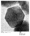
- FIG. 1 is an image of a secondary electron image by STEM observation of ferrite particles of Example 1.
- FIG. 2A is an image of a TEM image (magnification of 200,000 ⁇ ) of the ferrite particles of Example 1.
- FIG. 2B is an image of a TEM image (magnification of 400,000 times) of the ferrite particles of Example 1.
- FIG. 3 is an image of the ferrite particles of Example 1 by electron beam diffraction.
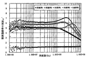
- FIG. 4 is a graph showing the frequency dependency of the real part ⁇ ′ of the complex permeability of the ferrite particles of Examples 1 to 2 and Comparative Examples 1 to 3.
- FIG. 5 is a graph showing the field strength dependency of the volume resistance of the soft magnetic mixed powders of Examples 3 to 4 and Comparative Examples 4 to 6.
- FIG. 6 is a graph showing the frequency dependency of the real part ⁇ ′ of the complex permeability of the soft magnetic mixed powders of Examples 3 to 4 and Comparative Examples 4 to 6.
- Mn—Zn Ferrite Particles according to the present invention contain 44 to 60% by mass of Fe, 10 to 16% by mass of Mn, and 1 to 11% by mass of Zn.
- the saturation magnetic flux density is high, and when used together with the soft magnetic powder, a magnetic permeability higher than that of the soft magnetic powder alone can be obtained.
- the Mn—Zn ferrite particles according to the present invention contain 44 to 60% by mass of Fe, 10 to 16% by mass of Mn, and 1 to 11% by mass of Zn. Therefore, the Mn—Zn ferrite particles according to the present invention can obtain a desired saturation magnetic flux density and a desired magnetic permeability.
- the content of Fe in the ferrite particles of the present invention is less than 44% by mass, the desired magnetic permeability can not be obtained, which is not preferable.
- the content of Fe exceeds 60% by mass, the composition is close to magnetite, residual magnetization is increased, and ferrite particles are easily aggregated, which is not preferable.
- the content of Fe in the ferrite particles of the present invention is preferably 45% by mass or more, and more preferably 45.5% by mass or more.
- the content of Fe in the ferrite particles of the present invention is preferably 58% by mass or less, more preferably 55% by mass or less.
- the content of Mn in the ferrite particles of the present invention is less than 10% by mass, the desired permeability may not be obtained, which is not preferable. In addition, it is not preferable because the residual magnetization is increased and the ferrite particles are easily aggregated. On the other hand, when the content of Mn exceeds 16% by mass, a high saturation magnetic flux density may not be obtained, which is not preferable.
- the content of Mn in the ferrite particles of the present invention is preferably 11% by mass or more, and more preferably 12% by mass or more.
- the content of Mn in the ferrite particles of the present invention is preferably 15% by mass or less, and more preferably 14% by mass or less.
- the content of Zn in the ferrite particles of the present invention is less than 1% by mass, the coercivity is too large, and the particle shape is not a polyhedron shape, but it is not preferable because it approaches a spherical shape.
- the content of Zn exceeds 11% by mass, a high saturation magnetic flux density can not be obtained, which is not preferable.
- the content of Zn in the ferrite particles of the present invention is preferably 2% by mass or more, and more preferably 3% by mass or more.
- the content of Zn in the ferrite particles of the present invention is preferably 10% by mass or less, more preferably 9% by mass or less.
- the Mn—Zn ferrite particles according to the present invention have an average particle diameter of 1 to 2000 nm, preferably 5 to 1500 nm, and more preferably 10 to 300 nm.
- the average particle diameter is in this range, the Mn—Zn ferrite particles and the soft magnetic powder are mixed to prepare a soft magnetic mixed powder, and when forming a magnetic core by the soft magnetic mixed powder, the Mn— The Zn-based ferrite particles enter the spaces between the particles of the soft magnetic powder, and excellent packing can be obtained. If the average particle diameter of the Mn—Zn ferrite particles is less than 1 nm, such particles are not preferable even if the Mn—Zn ferrite particles are surface-treated.
- the average particle diameter of the Mn-Zn ferrite particles exceeds 2000 nm, the Mn-Zn ferrite particles are less likely to enter into the gaps between the particles of the soft magnetic powder and the filling property is reduced or single crystals are obtained. Is not preferable because it becomes difficult.
- the average particle size of the ferrite particles can be determined as follows. First, ferrite particles are photographed at a magnification of 100,000 to 200,000 using FE-SEM (SU-8020, Hitachi High-Technologies Corporation) as a scanning electron microscope. At this time, ferrite particles 5 to 50 are contained in one field of view, and a plurality of fields of view are photographed in a state in which the shape of the ferrite particles is clearly visible. The captured SEM image is read into image analysis software (Image-Pro PLUS, Media Cybernetics) and image analysis is performed. Then, the horizontal Feret particle size of at least 200 particles of ferrite particles is measured by manual measurement from an image taken at a magnification of 100,000 to 200,000, and the average value is defined as "average particle size".
- the form of the Mn—Zn ferrite particles according to the present invention is a single crystal.
- the ferrite particle, which is a single crystal is excellent in frequency characteristics because the domain wall generated by the alternating magnetic field does not pass through the grain interface, and the maximum of the magnetic permeability due to the resonance of the domain wall is present on the low frequency side. An almost constant permeability can be obtained in a wide band from the point to the high frequency side.
- grain boundaries are generated in the fine structure in one grain in the process of crystal growth by firing.
- the crystal form of the ferrite particles is, for example, observing the presence or absence of grain boundaries of the ferrite particles from a TEM image of the ferrite particles using a transmission electron microscope HF-2100 Cold-FE-TEM (manufactured by Hitachi High-Technologies Corporation) It can be measured by
- the crystal form of the ferrite particles can be observed, for example, by photographing a limited field electron diffraction image using a transmission electron microscope HF-2100 Cold-FE-TEM (manufactured by Hitachi High-Technologies Corporation).
- the Mn—Zn ferrite particles according to the present invention have a polyhedral shape with an average sphericity of 0.85 or more and less than 0.95.
- the said ferrite particle becomes a polyhedron shape reflecting that it is a single crystal body. Therefore, particles having an average sphericity of less than 0.85 may have a single crystal structure broken due to segregation of the composition.
- particles having an average sphericity of 0.95 or more are spherical rather than polyhedral. Particles having a spherical shape have a large strain in the crystal lattice due to the surface of the particles being forcibly spheroidized. In that case, it is not preferable because it may affect various magnetic properties.
- the Mn—Zn ferrite particles according to the present invention have an average sphericity of 0.85 or more and less than 0.95, but in this case, they are polyhedral.
- the polyhedral shape (polyhedral shape) is typically a decahedron or more, preferably a decahedron or more and 100 or less, more preferably a 12 or more and 72 or less, and even more preferably a 14 or more and 24 or less.
- the shape of the Mn—Zn ferrite particles according to the present invention can be observed, for example, using a scanning transmission electron microscope HD-2700 Cs-corrected STEM (manufactured by Hitachi High-Technologies Corporation).
- the average sphericity of the above-mentioned ferrite particles is an average value of practical sphericity of Wadell and can be determined as follows. First, image analysis is performed in the same manner as for the average particle size, and for ferrite particles of at least 200 particles, the diameter of a circle equal to the projected area of the particles and the diameter of the smallest circle circumscribing the projected image of the particles are determined.
- the Mn—Zn ferrite particles preferably have a BET specific surface area of 1 to 30 m 2 / g.
- the BET specific surface area is less than 1 m 2 / g, it means that the particles are large.
- the BET specific surface area is 1 or more, the voids between the particles do not become large when the particles are mixed with the resin and used as a filler, and the filler filling ratio can be increased, which is preferable.
- ferrite particles composed of Mn, Zn and Fe described in this patent often produce particles with smooth surface states, so usually, the BET specific surface area of Mn-Zn ferrite particles is 30 m 2 / g It does not exceed.
- the Mn—Zn ferrite particles according to the present invention can obtain predetermined magnetic properties by having the above composition and the above particle form. Note that these magnetic properties are not measured in the powder state of the Mn—Zn ferrite particles, but are measured in the state of being filled in a cell or pressed.
- the Mn—Zn ferrite particles according to the present invention can obtain a saturation magnetic flux density of 4000 to 5000 gauss.
- the saturation magnetic flux density is 4000 gausses or more, it is preferable to use the ferrite particle as a constituent material of the magnetic core, because the magnetic core can be miniaturized.
- the saturation magnetic flux density may exceed 5000 gauss, it is usually difficult to realize a saturation magnetic flux density exceeding 5000 gauss in the Mn--Zn ferrite particles of the above composition and the above particle form.
- 10000 Gauss (G) 1 Tesla (T).
- the Mn—Zn ferrite particles according to the present invention preferably have a saturation magnetization of 50 to 65 Am 2 / kg.
- the ferrite particles are filled in a predetermined cell, and the magnetization when a magnetic field of 5 K ⁇ 1000 / 4 ⁇ ⁇ A / m is applied by a magnetic measurement device is referred to as “saturation magnetization”.
- a saturation magnetization of 50 Am 2 / kg or more is preferable because a saturation magnetic flux density of 4000 to 5000 gausses can be easily obtained.
- the saturation magnetization may exceed 65 Am 2 / kg, but in the case of Mn-Zn ferrite particles of the above composition and the above particle shape, if it exceeds 65 Am 2 / kg, residual magnetization tends to be large, and the magnetic permeability of ferrite particles Frequency characteristics may be degraded.
- the Mn—Zn ferrite particles according to the present invention preferably have a residual magnetization of less than 8 Am 2 / kg.
- the applied magnetic field is decreased to make the MH hysteresis on the recording paper.
- a loop is created, and the magnetization when the applied magnetic field is 0 K ⁇ 1000 / 4 ⁇ ⁇ A / m in this loop is referred to as “residual magnetization”.
- the said ferrite particle can prevent aggregation of particle
- magnetic metal powder such as iron powder
- the Mn—Zn ferrite particles according to the present invention preferably have a coercive force of 60 to 80 Oe.
- the coercive force is defined as the magnitude of the magnetic field when the magnetization becomes zero by applying an external magnetization in the reverse direction from the state where there is residual magnetization in the MH hysteresis loop.
- the ferrite particles can realize low loss because the coercive force is as low as 60 to 80 Oe.
- the real part ⁇ 'of the complex permeability represents a normal permeability component, and the imaginary part ⁇ " Represents a loss.
- the real part ⁇ ′ of the complex permeability exhibits a constant value on the low frequency side. As the frequency increases, it decreases linearly.
- the real part ⁇ ′ of the complex permeability indicates a numerical value of a certain value or more exceeding 1 not only in the frequency band of 1 to 100 MHz but also in the frequency band of 100 MHz to 1 GHz.
- the real part ⁇ 'of the complex permeability of the Mn-Zn ferrite particles according to the present invention may or may not show a maximum, and the maximum of the real part ⁇ ' is considered to be due to the susceptibility to domain wall resonance. It is done.
- the amount of Fe 2+ is preferably 0.1% by mass or less. Setting the amount of Fe 2+ to 0.1% by mass or less is preferable because a large amount of magnetite does not exist on the surface of the ferrite particles. Magnetite acts to lower the electrical resistance of ferrite particles and to increase the remanent magnetization.
- the amount of Fe 2+ can be measured by redox titration with potassium permanganate solution. The redox titration can be carried out according to JIS M 8213, and potassium permanganate can be used instead of potassium dichromate.
- the true density of the ferrite particles of the present invention is 4.9 g / cm 3 to 5 with a view to maximizing the capability of the magnetic properties in the resin composition by increasing the filling rate when mixed with the resin. It is preferably 0 g / cm 3 .
- the measurement of the true density can be performed by a gas replacement method in accordance with JIS Z 8807: 2012.
- the ferrite particles of the present invention contain 44 to 60% by mass of Fe, 10 to 16% by mass of Mn, and 1 to 11% by mass of Zn, but may contain other metal components.
- Other metal components include Li, Si, Ca, Ti, Al, Cu and the like.
- the ferrite particles of the present invention may contain components other than Fe, Mn and Zn as metal components, but it is preferable to contain only Fe, Mn and Zn as metal components.
- the Mn—Zn ferrite particles can be obtained, for example, as follows. First, the granulated product made of a ferrite material is subjected to primary firing, and then thermally sprayed in the air to melt and ferrite the primary fired powder. And, after rapidly cooling and solidifying the obtained ferrite particles, only ferrite particles having a particle diameter of a predetermined range or less are recovered.
- the method for producing the Mn—Zn ferrite particles will be described in detail.
- the method for preparing the above-mentioned ferrite raw material is not particularly limited, and a conventionally known method can be adopted, and a dry method or a wet method may be used.
- the method of preparing the ferrite raw material (granulate), after weighing the Zn raw material, the Mn raw material, and the Fe raw material so as to obtain a desired ferrite composition, water is added and pulverized to prepare a slurry. .
- the prepared slurry is granulated with a spray drier and classified to prepare a granulated material having a predetermined particle size.
- the particle size of the granulated product is preferably about 5 to 30 ⁇ m in consideration of the particle size of the obtained ferrite particles.
- ferrite raw materials whose composition is prepared are mixed, subjected to dry grinding, each raw material is ground and dispersed, the mixture is granulated with a granulator, and classified to obtain granulated particles having a predetermined particle diameter. You may prepare a thing.
- the granules thus prepared are subjected to primary firing in the atmosphere.
- Primary firing is performed by maintaining the temperature at 850 to 1250 ° C. for 2 to 6 hours, and then grinding. Thereby, primary fired powder having an average particle diameter of 3.5 to 28 ⁇ m is obtained.
- the thermal spraying temperature is preferably 1000 to 3500 ° C., and more preferably 2000 to 3500 ° C.
- a mixed gas of combustion gas and oxygen can be used as a combustible gas combustion flame, and the volume ratio of combustion gas to oxygen is 1: 3.5 to 6.0. If the proportion of oxygen in the combustible gas combustion flame is less than 3.5 with respect to the combustion gas, melting may be insufficient, and if the proportion of oxygen exceeds 6.0 with respect to the combustion gas, ferritization may occur. It will be difficult. For example, it can be used in a proportion of oxygen 35 ⁇ 60Nm 3 / hr against the combustion gases 10 Nm 3 / hr.
- propane gas, propylene gas, acetylene gas etc. can be used, Especially propane gas can be used suitably.
- nitrogen, oxygen or air can be used as a granule-carrying gas in order to carry the granules during combustible gas combustion.
- the flow velocity of the granules to be conveyed is preferably 20 to 60 m / sec.
- the primary fired powder is melted and ferriteified, and a part of the ferrite component is vaporized. More specifically, since the temperature of the gas frame is higher than any of the boiling points of Fe, Mn, and Zn, which are elements constituting the primary fired powder, when the primary fired powder passes through the high temperature gas frame , Those elements are vaporized on the surface of the primary fired powder. Then, single crystal particles are generated by the precipitation of these elements in the process of cooling the particles that have passed through the gas frame. However, not all the primary fired powder is vaporized, and the non-vaporized primary fired powder is melted when passing through the gas frame, is spheroidized by surface tension, and is cooled after passing through the gas frame.
- the ferrite particles produced from the non-vaporized primary fired powder have a particle size close to that of the primary fired powder, the ferrite particles produced from the components vaporized from the primary fired powder are much smaller than the primary fired powder It will have a particle size.
- the ferrite particles generated by the thermal spraying are carried on the air flow by air supply in the atmosphere to collect and collect the ferrite particles having an average particle diameter of 1 to 2000 nm.
- the above-described collection transports the rapidly solidified and precipitated ferrite particles in an air flow by supplying air, and particles having a large particle diameter fall on the way of air flow transportation, while the other particles flow to the downstream. It can carry out by the method of collecting the ferrite particle
- the flow velocity at the time of air flow conveyance By setting the flow velocity at the time of air flow conveyance to 20 to 60 m / sec, ferrite particles having a large particle diameter are dropped on the way of air flow conveyance, and only ferrite particles having an average particle diameter in the above range are efficiently downstream of the air flow. It can be recovered. If the flow velocity is less than 20 m / sec, even ferrite particles with a small particle diameter will fall on the way of air flow, so the average particle diameter of ferrite particles recovered downstream of the air flow will be less than 1 nm, or It is not preferable because the absolute amount of ferrite particles recovered downstream of the air flow is reduced to lower the productivity. On the other hand, if the flow velocity exceeds 60 m / sec, even large ferrite particles having a large particle diameter are also transported to the downstream, and the average particle diameter of the ferrite particles recovered downstream of the airflow may exceed 2000 nm.
- the recovered ferrite particles are classified as necessary to adjust the particle size to a desired particle size.
- a classification method an existing air classification, mesh filtration method, sedimentation method or the like can be used.
- ferrite particles having a particle size of greater than 2000 nm may be removed by classification.
- Mn—Zn ferrite particles having an average particle diameter of 1 to 2000 nm can be obtained.
- the obtained Mn—Zn ferrite particles are preferably subjected to surface treatment with a coupling agent.
- the surface treatment with a coupling agent can further improve the dispersibility of the ferrite particles in the resin.
- various silane coupling agents, titanate coupling agents and aluminate coupling agents can be used, and more preferably decyltrimethoxysilane, decyltriethoxysilane, n-octyltriethoxysilane It can be used.
- the amount of surface treatment depends on the BET specific surface area of the ferrite particles, but is preferably 0.05 to 2% by mass with respect to the ferrite particles in terms of a silane coupling agent.
- the Mn—Zn ferrite particles according to the present invention are suitable for magnetic cores (cores, yokes), inductors and the like because they have the above-mentioned magnetic performance.
- the magnetic core or the like may be constituted by Mn-Zn ferrite particles alone, or the magnetic core or the like may be constituted by a resin molded body containing Mn-Zn ferrite particles and a resin, or Mn-Zn
- the magnetic core or the like may be made of soft magnetic mixed powder containing ferrite particles and soft magnetic powder.
- the present invention also relates to a magnetic core containing the soft magnetic powder mixture.
- the magnetic permeability can be increased as compared with the soft magnetic powder alone, and the electric resistance is high. can do.
- the permeability of the soft magnetic mixed powder can realize a value higher than the arithmetic calculation value of the permeability considering the weight mixing ratio of the Mn—Zn ferrite particles to the soft magnetic powder.
- the resin used together with the Mn-Zn ferrite particles in forming the resin molded product is not particularly limited as long as the effects of the present invention are not impaired.
- epoxy resin, urethane resin, silicone resin, PPS resin , LCP resin can be used.
- the content of the Mn—Zn ferrite particles of the present invention in the resin molded body is preferably 10 to 98% by mass, more preferably 30 to 98% by mass, with respect to the total amount of the resin molded body. More preferably, it is 45 to 98% by mass.
- the soft magnetic powder used together with the Mn—Zn ferrite particles in forming the soft magnetic mixed powder is not particularly limited as long as the effects of the present invention are not impaired.
- Iron alloy powder and ferrite particles which are oxide magnetic materials can be used.
- Iron powder, iron alloy powder, such as carbonyl iron powder, Fe-Si alloy powder, Fe-Si-Al alloy powder, Fe-Si-Cr alloy powder, Fe-Ni alloy powder, various iron powder and iron alloy powder Can be used.
- Carbonyl iron powder is a powder produced by heating and reacting reduced iron obtained by reducing ferric oxide and carbon monoxide under pressure.
- Ferrite particles include Ni-Zn ferrite, Ni-Zn-Cu ferrite, Mg-Zn ferrite, Mn-Mg ferrite, Mn-Zn ferrite (other than the Mn-Zn ferrite particles of the present invention), etc. Can be used.
- these soft magnetic powders for example, those having an average particle diameter of 2 to 20 ⁇ m can be suitably used.
- the average particle diameter of the soft magnetic powder is less than 2 ⁇ m, the particle diameter is about the same as the particle diameter of the ferrite particles according to the present invention, and thus Mn—Zn ferrite particles are contained in the voids between the particles of the soft magnetic powder. Comes in. Therefore, a space
- the average particle size of the soft magnetic powder exceeds 20 ⁇ m, it is necessary to add a large amount of ferrite particles in order to fill the voids with ferrite particles because the voids between the particles of the soft magnetic powder are large. is there.
- the mixing ratio of the Mn—Zn ferrite particles to the soft magnetic powder in the soft magnetic mixed powder is 5 to 50:95 to 50 (Mn—Zn ferrite particles: soft magnetic powder (mass ratio) is 5 to 50: 95 to 50) is preferable, 7.5 to 50: 92.5 to 50 is more preferable, and 10 to 30: 90 to 70 is more preferable.
- the content of the Mn-Zn ferrite particles in the soft magnetic mixed powder is preferably 5 to 50% by mass with respect to the total amount of the Mn-Zn ferrite particles and the soft magnetic powder, and is 7.5 to 50 mass. %, More preferably 10 to 30% by mass.
- the content of the Mn—Zn ferrite particles is 5% by mass or more, the effect of increasing the electrical resistance is not reduced, which is preferable.
- the content of the Mn—Zn ferrite particles is 50% by mass or less, the magnetic permeability is easily increased, which is preferable.
- Ferrite Particles Iron oxide (Fe 2 O 3 ), manganese oxide (MnO) and zinc oxide (ZnO) were weighed and mixed at a molar ratio of 59:30:11. Water was added to the obtained raw material mixture, followed by grinding to prepare a slurry with a solid content of 50% by mass. The prepared slurry was granulated with a spray drier, subjected to primary firing, and classified with an air flow classifier to produce a granulated product having an average particle diameter of 25 ⁇ m.
- the obtained granulated product is held in the air at 1100 ° C. for 4 hours, and then ground by a hammer mill to obtain a primary fired powder having an average particle diameter of 20 ⁇ m.
- the thermal spraying temperature (firing temperature) was 2000.degree.
- it was rapidly cooled in the atmosphere by being carried and carried in the air flow by air supply. Because the granules were sprayed and quenched while flowing continuously, the obtained particles were independent without binding to each other. Subsequently, the cooled particles were collected by a bag filter provided on the downstream side of the air flow.
- Example 2 In this example, ferrite particles were produced in the same manner as in Example 1 except that the raw material mixture was prepared with iron oxide, manganese oxide and zinc oxide in molar ratio of 52.5: 36.6: 10.9. .
- Comparative Example 1 In the present comparative example, ferrite particles were produced in the same manner as in Example 1 except that the raw material mixture was prepared using iron oxide, manganese oxide and zinc oxide in a molar ratio of 50: 35.5: 14.5.
- Comparative Example 2 In this comparative example, ferrite particles were produced in the same manner as in Example 1 except that a raw material mixture was prepared with iron oxide and manganese oxide in a molar ratio of 80:20 without adding zinc oxide.
- Comparative Example 3 In this comparative example, ferrite particles were produced in the same manner as in Example 1 except that the raw material mixture was prepared using only iron oxide without adding manganese oxide and zinc oxide.
- the content of the metal component in the ferrite particles was measured as follows. First, 0.2 g of ferrite particles was weighed, and a mixture of 20 mL of 1 N hydrochloric acid and 20 mL of 1 N nitric acid in 60 mL of pure water was heated to prepare an aqueous solution in which the ferrite particles were completely dissolved. The obtained aqueous solution was set in an ICP analyzer (ICPS-1000IV, Shimadzu Corporation), and the content of the metal component in the ferrite particles was measured. In addition, the composition ratio (chemical analysis result) of a ferrite particle does not correspond with the composition ratio (calculated value) in a raw material mixture. The reason is considered that the vaporization rate and the deposition rate of each element are different in the process of spraying the primary fired particles to form ferrite particles because the saturation vapor pressure of each element of Fe, Mn and Zn is different. Be
- the horizontal Feret diameter measured by the above-described method was taken as the average particle diameter.
- FIG. 1 shows an image of a secondary electron image (magnification of 200,000) by STEM observation of the ferrite particles of Example 1.
- FIG. 1 shows an image of a secondary electron image (magnification of 200,000) by STEM observation of the ferrite particles of Example 1.
- the sphericity of the ferrite particles 100 was measured by the method described above, and the average value (average sphericity) was calculated.
- FIG. 2A is a magnification of 200,000 and FIG. 2B is a magnification of 400,000.
- Fe 2+ amount The presence or absence of Fe 2+ in the Mn—Zn ferrite particles was evaluated by redox titration with a potassium permanganate solution.
- the redox titration was performed according to JIS M 8213, and potassium permanganate was used instead of potassium dichromate.
- BET specific surface area The measurement of the BET specific surface area was performed using a specific surface area measuring device (Macsorb HM model-1208, Mountech Co., Ltd.). First, about 10 g of the obtained ferrite particles are placed on a medicine packing paper, degassed by a vacuum drier, and after confirming that the degree of vacuum is -0.1 MPa or less, the ferrite particles are heated at 200 ° C. for 2 hours The water adhering to the surface of was removed. Subsequently, about 0.5 to 4 g of the ferrite particles from which water was removed was placed in a standard sample cell dedicated to the device, and accurately weighed using a precision balance.
- the weighed ferrite particles were set to the measurement port of the apparatus and measured.
- the measurement was performed by one-point method.
- the measurement atmosphere was a temperature of 10 to 30 ° C. and a relative humidity of 20 to 80% (without condensation).
- true density The measurement of the true density was performed using a pycnometer in accordance with JIS Z 8807: 2012. The measurement was performed at a temperature of 25 ° C. using methanol as a solvent.
- the measurement of the magnetic properties was performed using a vibrating sample magnetometer (VSM-C7-10A, Toei Kogyo Co., Ltd.).
- VSM-C7-10A vibrating sample magnetometer
- the obtained ferrite particles were filled in a cell with an inner diameter of 5 mm and a height of 2 mm, and set in the above-described apparatus.
- a magnetic field was applied and swept to 5K ⁇ 1000 / 4 ⁇ ⁇ A / m.
- the applied magnetic field was reduced, and an MH hysteresis loop representing the relationship between the magnetization M and the magnetic field H was created on the recording paper.
- the magnetization when the applied magnetic field is 5K ⁇ 1000 / 4 ⁇ ⁇ A / m is saturation magnetization
- the magnetization when the applied magnetic field is 0K ⁇ 1000 / 4 ⁇ ⁇ A / m is residual magnetization
- the residual magnetization is The coercivity is defined as the magnitude of the magnetic field when the magnetization becomes zero by applying an external magnetization in the reverse direction from a certain state.
- the magnetic flux density when the applied magnetic field was 5 K ⁇ 1000 / 4 ⁇ ⁇ A / m was taken as the saturation magnetic flux density.
- the magnetic permeability of the ferrite particles of Examples 1 and 2 and Comparative Examples 1 to 3 was measured as follows. The permeability was measured using an E4991A RF impedance / material analyzer 16454A magnetic material measurement electrode manufactured by Agilent Technologies. First, in 100 cc of a polyethylene container, 4.5 g of ferrite particles of Examples 1 and 2 and Comparative Examples 1 to 3 and 0.5 g of a fluorine-based powder resin (KYNAR (registered trademark) 301F, average particle diameter 0.5 ⁇ m). The solution was contained and stirred for 30 minutes in a ball mill of 100 rpm and mixed.
- KYNAR registered trademark
- volume resistance The measurement of volume resistance was performed as follows. First, the Mn-Zn ferrite particles of Examples 1 and 2 and the soft magnetic powder are accommodated in a 100 cc polyethylene container, and stirred for 30 minutes with a ball mill of 100 rpm and mixed to obtain the soft magnetic properties of Examples 3 to 4. A mixed powder was prepared. As the soft magnetic powder, iron powder (carbonyl iron powder) having an average particle diameter of 3.5 ⁇ m was used.
- the soft magnetic mixed powder of Example 3 is prepared by mixing the ferrite particles of Example 1 and iron powder at a mass ratio of 10:90, and the soft magnetic mixed powder of Example 4 is The ferrite particles of Example 2 are used in place of the ferrite particles of Example 1. Also, soft magnetic mixed powders of Comparative Examples 4 to 6 were prepared.
- the soft magnetic mixed powder of Comparative Example 4 uses only iron powder without using any ferrite particles, and the soft magnetic mixed powder of Comparative Example 5 has an average particle diameter of 200 nm instead of the ferrite particles of Example 1. are those with TiO 2 particles, the soft magnetic mixed powder of Comparative example 6 is obtained by using the SiO 2 particles having an average particle diameter of 12 nm (primary particle size).
- the soft magnetic mixed powders of Examples 3 to 4 and Comparative Examples 4 to 6 obtained were compared with a 1 kg weight placed on a fluorocarbon resin cylinder having a cross section of 1.77 cm 2 and a height of 4 mm.
- the sample for measurement was produced by filling so that it might become. Electrodes are attached to both ends of the measurement sample, and a measurement voltage is applied in the range of 0 to 1000 V to the above electrodes using a Keithley 6517A insulation resistance measuring instrument, and a current when 10 seconds have elapsed after the application. The value was measured. Then, the volume resistance was calculated from the cross-sectional area of the jig, the height of the measurement sample, the applied voltage, and the current value. The results are shown in FIG. 5 and Table 3. The soft magnetic mixed powders of Comparative Examples 4 to 5 could not calculate volume resistance because their electrical resistance was excessively low.
- the measuring method of the magnetic permeability of the above-mentioned ferrite particles is the same as that of the above-mentioned ferrite particles except that 4.5 g of the soft magnetic mixed powders of Examples 3 to 4 and Comparative Examples 4 to 6 are used instead of 4.5 g of ferrite particles.
- the permeability of the soft magnetic mixed powder was measured.
- FIGS. 1 and 2A it can be seen that the ferrite particles of Example 1 have a polyhedral particle shape. From FIG. 2B, it can be seen that the ferrite particles of Example 1 are single crystals because no grain boundaries are observed inside the ferrite particles. Moreover, FIG. 3 also shows that the ferrite particle of Example 1 is a single crystal. And when it observed similarly to Example 1 about the ferrite particle of Example 2, it turned out that the particle shape and crystal form similar to the ferrite particle of Example 1 are equipped.
- the ferrite particles of Examples 1 and 2 have a high saturation magnetic flux density as compared to the Mn—Zn ferrite particles disclosed in Patent Document 1.
- the Fe content is less than 44% by mass, the Zn content is more than 11% by mass, and the Fe content is smaller compared to the ferrite particles of Examples 1 and 2 and Zn content is high.
- the ferrite particles of Comparative Example 1 have lower saturation magnetization and saturation magnetic flux density than the ferrite particles of Example 1 and Example 2.
- the ferrite particles of Comparative Example 2 contain Fe and Mn but do not contain Zn, and the ferrite particles of Comparative Example 3 contain Fe but do not substantially contain Mn and Zn.
- Mn contained in the ferrite particle of the comparative example 3 is considered to be an unavoidable impurity originating in the impurity contained in iron oxide which is a raw material.
- ferrite particles of Comparative Examples 2 to 3 have high saturation magnetization and saturation magnetic flux density but high coercivity as compared with the ferrite particles of Examples 1 to 2, they are not suitable for use as magnetic cores or inductors. It is considered to be.
- the permeability (real part ⁇ ′ of the complex permeability) of the ferrite particles of Examples 1 and 2 is 5.5 to 6.5 in the frequency band of 1 to 100 MHz, It has a peak of 6 to 7 in the frequency band of 200 to 300 MHz, and it gradually decreases when it exceeds 300 MHz, and is about 3 even at 1 GHz. From this, it is understood that the ferrite particles of Examples 1 and 2 can reduce the frequency fluctuation of the magnetic permeability as compared with the Mn—Zn ferrite particles disclosed in Patent Document 1. The ferrite particles of Examples 1 and 2 can obtain higher permeability than the ferrite particles of Comparative Examples 1 and 3.
- the soft magnetic mixed powders of Examples 3 to 4 containing the ferrite particles of Examples 1 and 2 and the soft magnetic powder are soft as soft magnetic mixed powders of Comparative Example 4.
- the volume resistance can be increased as compared with the magnetic powder alone.
- the soft magnetic mixed powders of Examples 3 to 4 including the ferrite particles of Examples 1 and 2 and the iron powder are compared with the soft magnetic powder alone of Comparative Example 4.
- the permeability (the real part ⁇ ′ of the complex permeability) can be increased, and the actual measurement value is higher than the arithmetic calculation value.
- the soft magnetic metal composite (soft magnetic mixed powder) disclosed in Patent Document 2 includes soft magnetic metal powder (soft magnetic powder) and NiZn ferrite nanopowder as insulator nanopowder. The permeability is lower than that of the soft magnetic metal powder alone.
- the Mn—Zn ferrite particles of Examples 1 and 2 are different from NiZn ferrite and NiCuZn ferrite disclosed as insulator nanopowders in Patent Document 2, and when used together with soft magnetic powder, It can be seen that the permeability can be improved as compared to powder alone.
- the soft magnetic mixed powder of Comparative Example 5 containing TiO 2 particles and iron powder has lower volume resistance and permeability as compared with the soft magnetic mixed powder of Examples 3 to 4. Low.
- the soft magnetic mixed powder of Comparative Example 6 containing SiO 2 particles and iron powder has a significantly higher volume resistance but lower permeability than the soft magnetic mixed powder of Examples 3 to 4. From this, as the powder to be combined with the soft magnetic powder, the ferrite particles of Examples 1 and 2 are preferable to TiO 2 particles and SiO 2 particles, and the effect of increasing volume resistance and increasing permeability is excellent. I understand that.
- the Mn--Zn ferrite particles according to the present invention have high saturation magnetic flux density and, when mixed with soft magnetic powder and used as soft magnetic mixed powder, obtain higher magnetic permeability than soft magnetic powder alone. be able to. Therefore, the said ferrite particle is suitable for uses, such as a magnetic core and an inductor.
- the Mn-Zn ferrite particles according to the present invention have a small particle size and a small residual magnetization and coercive force, they agglomerate when the ferrite particles are dispersed in a resin solution or a dispersion medium. It has the advantage of being difficult. Therefore, the said ferrite particle can be used suitably for the magnetic ink, the shaping
Landscapes
- Chemical & Material Sciences (AREA)
- Organic Chemistry (AREA)
- Engineering & Computer Science (AREA)
- Inorganic Chemistry (AREA)
- Power Engineering (AREA)
- Dispersion Chemistry (AREA)
- Metallurgy (AREA)
- Crystallography & Structural Chemistry (AREA)
- Materials Engineering (AREA)
- Polymers & Plastics (AREA)
- Medicinal Chemistry (AREA)
- Chemical Kinetics & Catalysis (AREA)
- Health & Medical Sciences (AREA)
- Soft Magnetic Materials (AREA)
- Compositions Of Macromolecular Compounds (AREA)
- Compounds Of Iron (AREA)
Abstract
Description
[1]
Feを44~60質量%、Mnを10~16質量%、Znを1~11質量%含有するMn-Zn系フェライト粒子であって、
当該フェライト粒子は、平均粒径が1~2000nmの単結晶体であり、且つ、平均球形度が0.85以上0.95未満であって多面体状の粒子形状を備えることを特徴とするMn-Zn系フェライト粒子。
[2]
前記フェライト粒子の飽和磁化が50~65Am2/kgである[1]に記載のMn-Zn系フェライト粒子。
[3]
前記フェライト粒子の平均粒径が5~1500nmである[1]又は[2]に記載のMn-Zn系フェライト粒子。
[4]
[1]から[3]のいずれか一項に記載のMn-Zn系フェライト粒子を含有することを特徴とする樹脂成形体。
[5]
[1]から[3]のいずれか一項に記載のMn-Zn系フェライト粒子と、軟磁性粉末とを含むことを特徴とする軟磁性混合粉。
[6]
[5]に記載の軟磁性混合粉を含むことを特徴とする磁芯。
<本発明に係るMn-Zn系フェライト粒子>
本発明に係るMn-Zn系フェライト粒子(以下、「本発明のフェライト粒子」ともいう)は、Feを44~60質量%、Mnを10~16質量%、Znを1~11質量%含有するMn-Zn系フェライト粒子であって、当該フェライト粒子は、平均粒径が1~2000nmの単結晶体であり、且つ、平均球形度が0.85以上0.95未満であって多面体状の粒子形状を備えることを特徴とする。本発明に係るMn-Zn系フェライト粒子によれば、飽和磁束密度が高く、軟磁性粉末と共に用いられたときに当該軟磁性粉末単体よりも高い透磁率を得ることができる。
本発明に係るMn-Zn系フェライト粒子は、Feを44~60質量%、Mnを10~16質量%、Znを1~11質量%含有する。このため、本発明に係るMn-Zn系フェライト粒子は、所望の飽和磁束密度と所望の透磁率を得ることができる。
本発明のフェライト粒子におけるFeの含有量は、好ましくは45質量%以上であり、更に好ましくは、45.5質量%以上である。
本発明のフェライト粒子におけるFeの含有量は、好ましくは58質量%以下であり、更に好ましくは、55質量%以下である。
本発明のフェライト粒子におけるMnの含有量は、好ましくは11質量%以上であり、更に好ましくは、12質量%以上である。
本発明のフェライト粒子におけるMnの含有量は、好ましくは15質量%以下であり、更に好ましくは、14質量%以下である。
本発明のフェライト粒子におけるZnの含有量は、好ましくは2質量%以上であり、更に好ましくは、3質量%以上である。
本発明のフェライト粒子におけるZnの含有量は、好ましくは10質量%以下であり、更に好ましくは、9質量%以下である。
本発明に係るMn-Zn系フェライト粒子は、平均粒径が1~2000nmであり、5~1500nmであることが好ましく、10~300nmであることがより好ましい。平均粒径がこの範囲であることにより、Mn-Zn系フェライト粒子と軟磁性粉末とを混合して軟磁性混合粉を調製して当該軟磁性混合粉によって磁芯を形成するときに、Mn-Zn系フェライト粒子が軟磁性粉末の粒子間の空隙に入り込み、優れた充填性を得ることができる。Mn-Zn系フェライト粒子の平均粒径が1nm未満では、Mn-Zn系フェライト粒子に表面処理を行ったとしても当該粒子が凝集してしまうため好ましくない。一方、Mn-Zn系フェライト粒子の平均粒径が2000nmを超えると、Mn-Zn系フェライト粒子が軟磁性粉末の粒子間の空隙に入り込みづらくなって充填性が低下したり、単結晶を得るのが困難になるため好ましくない。
本発明に係るMn-Zn系フェライト粒子は、その形態が単結晶体である。単結晶体である当該フェライト粒子は、交流磁場により生成された磁壁が粒界面を通過することがないため周波数特性に優れる上に、磁壁の共鳴による透磁率の極大があったとしても低周波側から高周波側までの幅広い帯域においてほぼ一定の透磁率を得ることができる。一方、多結晶体であるフェライト粒子の場合には、焼成による結晶成長の過程で1粒子内の微細構造において結晶粒界が生じる。そして、交流磁場により生成された磁壁が粒界面を通過するときに結晶粒界で磁壁が足止めされ、周波数特性が低下するため好ましくない。
フェライト粒子の結晶形態は、例えば、透過型電子顕微鏡HF-2100 Cold-FE-TEM(株式会社日立ハイテクノロジーズ製)を用いてフェライト粒子のTEM像からフェライト粒子の結晶粒界の有無を観察することで測定することができる。
本発明に係るMn-Zn系フェライト粒子は、平均球形度が0.85以上0.95未満である多面体状である。当該フェライト粒子は、単結晶体であることを反映して多面体状となる。そのため、平均球形度が0.85未満である粒子は、組成の偏析により単結晶構造が崩れていることがある。一方、平均球形度が0.95以上である粒子では、多面体状というよりもむしろ球体状である。球体状である粒子は、粒子表面が強制的に球状化されることで結晶格子のひずみが大きい。その場合、様々な磁気特性に影響を与えるおそれがあるため好ましくない。
なお、多面体状(多面体形状)とは、典型的には10面体以上であり、10面体以上100面体以下が好ましく、12面体以上72面体以下がより好ましく、14面体以上24面体以下がさらに好ましい。
本発明に係るMn-Zn系フェライト粒子の形状は、例えば、走査透過電子顕微鏡HD-2700 Cs-corrected STEM(株式会社日立ハイテクノロジーズ製)を用いて観察することができる。
上記フェライト粒子の平均球形度は、Wadellの実用球形度の平均値であり、次のようにして求めることができる。まず、平均粒径と同様に画像解析を行い、少なくとも200粒子以上のフェライト粒子について、粒子の投影面積に等しい円の直径と、粒子の投影像に外接する最小円の直径とを求める。そして、以下の式(1)によって各粒子の球形度を算出し、その平均値を「平均球形度」とする。
球形度=(粒子の投影像に外接する最小円の直径)/(粒子の投影面積に等しい円の直径)・・・(1)
上記Mn-Zn系フェライト粒子は、BET比表面積が1~30m2/gであることが好ましい。BET比表面積が1m2/g未満では粒子が大きいことを意味している。BET比表面積が1以上の場合、当該粒子を樹脂に混合してフィラーとして使用する際に粒子間の空隙が大きくならず、フィラー充填率を高くすることができるため好ましい。一方、本特許記載のMn、Zn及びFeから組成されるフェライト粒子では表面状態が平滑な粒子が生成されることが多いため、通常、Mn-Zn系フェライト粒子のBET比表面積が30m2/gを超えることはない。
本発明に係るMn-Zn系フェライト粒子は、4000~5000ガウスの飽和磁束密度を得ることができる。飽和磁束密度が4000ガウス以上では、当該フェライト粒子を磁芯の構成材料としたときに磁芯の小型化を実現できるため好ましい。飽和磁束密度が5000ガウスを超えてもよいが、上記組成及び上記粒子形態のMn-Zn系フェライト粒子において、通常、5000ガウスを超える飽和磁束密度を実現するのは困難である。
なお、10000ガウス(G)=1テスラ(T)である。
本発明に係るMn-Zn系フェライト粒子は、飽和磁化が50~65Am2/kgであることが好ましい。なお、本明細書において、前記フェライト粒子を所定のセルに充填し、磁気測定装置で5K・1000/4π・A/mの磁場を印加したときの磁化を「飽和磁化」と称す。飽和磁化が50Am2/kg以上であると、4000~5000ガウスの飽和磁束密度を得られ易くなるため好ましい。飽和磁化が65Am2/kgを超えてもよいが、上記組成及び上記粒子形状のMn-Zn系フェライト粒子において、65Am2/kgを超える場合、残留磁化が大きくなりやすく、フェライト粒子の透磁率の周波数特性が悪くなる可能性がある。
本発明に係るMn-Zn系フェライト粒子は、残留磁化が8Am2/kg未満であることが好ましい。なお、本明細書において、前記フェライト粒子を所定のセルに充填し磁気測定装置で5K・1000/4π・A/mの磁場を印加した後に、印加磁場を減少させ、記録紙上にM-Hヒステリシスループを作成し、このループにおいて印加磁場が0K・1000/4π・A/mであるときの磁化を「残留磁化」と称す。当該フェライト粒子は、残留磁化が8Am2/kg未満であることにより、粒子の凝集を防ぎ優れた分散性を得ることができる。残留磁化が8Am2/kg以上であると、粒子が凝集して優れた分散性を得られないため好ましくない。また、当該フェライト粒子を鉄粉などの磁性金属粉と混合したときに当該磁性金属粉に吸着する等して、当該フェライト粒子と当該磁性金属粉とを均一に混合することができないため好ましくない。
本発明に係るMn-Zn系フェライト粒子は、保磁力が60~80Oeであることが好ましい。なお、本明細書において、上記M-Hヒステリシスループにおいて残留磁化がある状態から逆向きの外部磁化を印加して磁化がゼロになったときの磁場の大きさを保磁力とした。当該フェライト粒子は、保磁力が60~80Oeと低いために、低損失を実現することができる。平均粒径が1~2000nmであるMn-Zn系フェライト粒子では、通常、保磁力が60Oeを下回ることはない。保磁力が80Oe以下であれば、所望の透磁率を得られ易くなるため好ましい。
なお、1A/m=4π/103Oeである。
透磁率μは、一般的に複素透磁率μ=μ’-jμ”として表現される(jは虚数単位)。複素透磁率の実部μ’は通常の透磁率成分を表し、虚部μ”は損失を表す。本件発明に係るMn-Zn系フェライト粒子では、縦軸を複素透磁率の実部μ’としてグラフ化したときに、複素透磁率の実部μ’は、低周波数側では一定の値を示すものの、周波数が高くなるにつれて直線的に低下する。そして、複素透磁率の実部μ’は、1~100MHzの周波数帯域だけでなく100MHz~1GHzの周波数帯域においても1を上回る一定以上の数値を示す。なお、本件発明に係るMn-Zn系フェライト粒子の複素透磁率の実部μ’は極大を示す場合と示さない場合があり、実部μ’の極大は磁壁共鳴が起こりやすさに起因すると考えられている。
本発明のフェライト粒子において、Fe2+量は、0.1質量%以下であることが好ましい。Fe2+量を0.1質量%以下とすることで、フェライト粒子の表面にマグネタイトが多く存在しないため好ましい。マグネタイトは、フェライト粒子の電気抵抗を低下させ、且つ、残留磁化を高くする方向に作用する。
フェライト粒子において、Fe2+量は、過マンガン酸カリウム溶液による酸化還元滴定によって、測定することができる。酸化還元滴定はJIS M 8213に準じて行うことができ、二クロム酸カリウムの代わりに過マンガン酸カリウムを用いることもできる。
本発明のフェライト粒子の真密度は、樹脂と混合する際、高い充填率を上げることで、樹脂組成物における磁気特性の能力を最大限に発揮させる観点で、4.9g/cm3~5.0g/cm3であることが好ましい。
真密度の測定は、JIS Z 8807:2012に準拠して、気体置換法で行うことができる。
本発明のフェライト粒子は、金属成分としてFe、Mn、Zn以外の成分を含有していても良いが、金属成分として、Fe、Mn、Znのみ含有することが好ましい。
上記Mn-Zn系フェライト粒子は、例えば、次のようにして得ることができる。まず、フェライト原料からなる造粒物を一次焼成した後に、大気中で溶射することにより、一次焼成粉を溶融してフェライト化する。そして、得られたフェライト粒子を急冷凝固させた後、粒径が所定範囲以下のフェライト粒子のみを回収する。以下、Mn-Zn系フェライト粒子の製造方法について詳しく説明する。
本発明に係るMn-Zn系フェライト粒子は、上記磁気性能を備えることから、磁芯(コア、ヨーク)やインダクタ等に好適である。その場合、Mn-Zn系フェライト粒子単独で磁芯等を構成してもよく、Mn-Zn系フェライト粒子と樹脂とを含む樹脂成形体によって磁芯等を構成してもよく、Mn-Zn系フェライト粒子と軟磁性粉末とを含む軟磁性混合粉によって磁芯等を構成してもよい。
本発明は、前記軟磁性混合粉を含む磁芯にも関する。
樹脂成形体における本発明のMn-Zn系フェライト粒子の含有量は、樹脂成形体の全量に対して、10~98質量%であることが好ましく、30~98質量%であることがより好ましく、45~98質量%であることが更に好ましい。
軟磁性混合粉におけるMn-Zn系フェライト粒子の含有量は、Mn-Zn系フェライト粒子と軟磁性粉末の合計量に対して、5~50質量%であることが好ましく、7.5~50質量%であることがより好ましく、10~30質量%であることが更に好ましい。
Mn-Zn系フェライト粒子の含有量が5質量%以上の場合には、電気抵抗を高くする効果が減少しないため好ましい。一方、Mn-Zn系フェライト粒子の含有量が50質量%以下の場合には、透磁率が大きくなり易いため好ましい。
1.フェライト粒子の作製
〔実施例1〕
酸化鉄(Fe2O3)と酸化マンガン(MnO)と酸化亜鉛(ZnO)とをモル比で59:30:11の割合で計量し、混合した。得られた原料混合物に水を加えて粉砕し固形分50質量%のスラリーを作製した。作製されたスラリーをスプレードライヤーで造粒し、一次焼成を行い、気流分級機により分級して平均粒径25μmの造粒物を作製した。
本実施例では、酸化鉄と酸化マンガンと酸化亜鉛とをモル比で52.5:36.6:10.9として原料混合物を調製した以外は、実施例1と同様にしてフェライト粒子を作製した。
本比較例では、酸化鉄と酸化マンガンと酸化亜鉛とをモル比で50:35.5:14.5として原料混合物を調製した以外は、実施例1と同様にしてフェライト粒子を作製した。
本比較例では、酸化亜鉛を添加せずに酸化鉄と酸化マンガンとをモル比で80:20として原料混合物を調製した以外は、実施例1と同様にしてフェライト粒子を作製した。
本比較例では、酸化マンガン及び酸化亜鉛を添加せず酸化鉄のみを用いて原料混合物を調製した以外は、実施例1と同様にしてフェライト粒子を作製した。
得られた実施例1~2及び比較例1~3のフェライト粒子について、化学分析を行うと共に、平均粒径、粒子形状、平均球形度、結晶形態、スピネル相の有無、Fe2+量、BET比表面積、真密度及び磁気特性(飽和磁化、残留磁化、保磁力、飽和磁束密度)を測定した。各測定方法は以下のとおりである。結果を表2に示す。
フェライト粒子における金属成分の含有量は、次のようにして測定した。まず、フェライト粒子0.2gを秤量し、純水60mLに1Nの塩酸20mL及び1Nの硝酸20mLを加えたものを加熱し、フェライト粒子を完全溶解させた水溶液を調製した。得られた水溶液をICP分析装置(ICPS-1000IV、株式会社島津製作所)にセットし、フェライト粒子における金属成分の含有量を測定した。なお、フェライト粒子の組成比(化学分析結果)は、原料混合物における組成比(計算値)とは一致しない。その理由は、Fe、Mn及びZnの各元素の飽和蒸気圧が異なるために、一次焼成粒子を溶射してフェライト粒子を生成する過程における各元素の気化速度及び析出速度が異なるからであると考えられる。
上述した方法によって測定した水平フェレ径を平均粒径とした。
フェライト粒子の粒子形状は、走査透過電子顕微鏡HD-2700 Cs-corrected STEM(株式会社日立ハイテクノロジーズ製)を用いて観察した。加速電圧は200kVとした。図1に、実施例1のフェライト粒子のSTEM観察による二次電子像(倍率20万倍)の画像を示す。
上述した方法によってフェライト粒子100粒子について球形度を測定し、その平均値(平均球形度)を算出した。
フェライト粒子の結晶形態を評価するために、フェライト粒子を、透過型電子顕微鏡HF-2100 Cold-FE-TEM(株式会社日立ハイテクノロジーズ製)を用いて観察した。加速電圧は200kVとした。図2A及び図2Bに実施例1のフェライト粒子のTEM像の画像を示す。図2Aは倍率20万倍、図2Bは倍率40万倍である。
測定装置としてパナリティカル社製「X’Pert PRO MPD」を用いた。X線源としてCo管球(CoKα線)を用い、集中型光学系によって0.2°/secの連続スキャンで測定した。高速検出器として「X’Celarator」を用いた。測定結果は、通常の粉末の結晶構造解析と同様に解析用ソフトウエア「X’Pert HighScore」を用いて解析した。解析結果においてスピネル相の存在が確認されたときには「有」と判定し、存在が確認されなかったときには「無」と判定した。なお、スピネル相の存在が確認されたとき、その粒子(粉末)がソフトフェライトであることを意味している。
過マンガン酸カリウム溶液による酸化還元滴定によって、Mn-Zn系フェライト粒子におけるFe2+の有無を評価した。酸化還元滴定はJIS M 8213に準じて行い、二クロム酸カリウムの代わりに過マンガン酸カリウムを用いた。
BET比表面積の測定は、比表面積測定装置(Macsorb HM model-1208、株式会社マウンテック)を用いて行った。まず、得られたフェライト粒子約10gを薬包紙に載せ、真空乾燥機で脱気して真空度が-0.1MPa以下であることを確認した後に、200℃で2時間加熱することにより、フェライト粒子の表面に付着している水分を除去した。続いて、水分が除去されたフェライト粒子を当該装置専用の標準サンプルセルに約0.5~4g入れ、精密天秤で正確に秤量した。続いて、秤量したフェライト粒子を当該装置の測定ポートにセットして測定した。測定は1点法で行った。測定雰囲気は、温度10~30℃、相対湿度20~80%(結露なし)であった。
真密度の測定は、JIS Z 8807:2012に準拠して、ピクノメーターを用いて行った。溶媒としてメタノールを用い、温度25℃にて測定を行った。
磁気特性(飽和磁化、残留磁化、保磁力及び飽和磁束密度)の測定は、振動試料型磁気測定装置(VSM-C7-10A、東英工業株式会社)を用いて行った。まず、得られたフェライト粒子を内径5mm、高さ2mmのセルに充填し、上記装置にセットした。上記装置において、磁場を印加し、5K・1000/4π・A/mまで掃引した。次いで、印加磁場を減少させ、記録紙上に、磁化Mと磁場Hとの関係を表すM-Hヒステリシスループを作成した。このループにおいて、印加磁場が5K・1000/4π・A/mであるときの磁化を飽和磁化とし、印加磁場が0K・1000/4π・A/mであるときの磁化を残留磁化とし、残留磁化がある状態から逆向きの外部磁化を印加して磁化がゼロになったときの磁場の大きさを保磁力とした。また、印加磁場が5K・1000/4π・A/mであるときの磁束密度を飽和磁束密度とした。
実施例1~2及び比較例1~3のフェライト粒子について、以下のようにして透磁率を測定した。透磁率の測定は、アジレントテクノロジー社製E4991A型RFインピーダンス/マテリアル・アナライザ 16454A磁性材料測定電極を用いて行った。まず、実施例1~2及び比較例1~3のフェライト粒子4.5gとフッ素系粉末樹脂(KYNAR(登録商標)301F、平均粒径0.5μm)0.5gとを100ccのポリエチレン製容器に収容し、100rpmのボールミルで30分間撹拌して混合した。撹拌終了後、得られた混合物0.8g程度を、内径4.5mm、外径13mmのダイスに充填し、プレス機で40MPaの圧力で1分間加圧した。得られた成形体を熱風乾燥機によって温度140℃で2時間加熱硬化させることにより、測定用サンプルを得た。そして、測定用サンプルを測定装置にセットする共に、事前に測定しておいた測定用サンプルの外径、内径、高さを測定装置に入力した。測定は、振幅100mVとし、周波数1MHz~3GHzの範囲を対数スケールで掃引し、透磁率(複素透磁率の実部μ’)を測定した。但し、周波数2GHzを超える周波数帯域では測定冶具の影響が大きいために、測定結果は得られたが信頼できるものではないので考慮しないこととする。得られたグラフを図4に示す。
体積抵抗の測定は次のように行った。まず、実施例1~2のMn-Zn系フェライト粒子と軟磁性粉末とを100ccのポリエチレン製容器に収容し、100rpmのボールミルで30分間撹拌して混合することにより実施例3~4の軟磁性混合粉を調製した。前記軟磁性粉末としては、平均粒径3.5μmの鉄粉(カルボニル鉄粉)を用いた。
ここでは、フェライト粒子4.5gに代えて、実施例3~4及び比較例4~6の軟磁性混合粉4.5gを用いたこと以外は、上記フェライト粒子の透磁率の測定方法と同様にして、軟磁性混合粉の透磁率を測定した。さらに、実施例1~2のフェライト粒子、鉄粉、TiO2粒子及びSiO2粒子の周波数10MHzにおける透磁率(複素透磁率の実部μ’)の実測値を基に、実施例3~4及び比較例4~6の軟磁性混合粉について、10MHzにおける透磁率の算術計算値を算出した。結果を図6及び表3に示す。
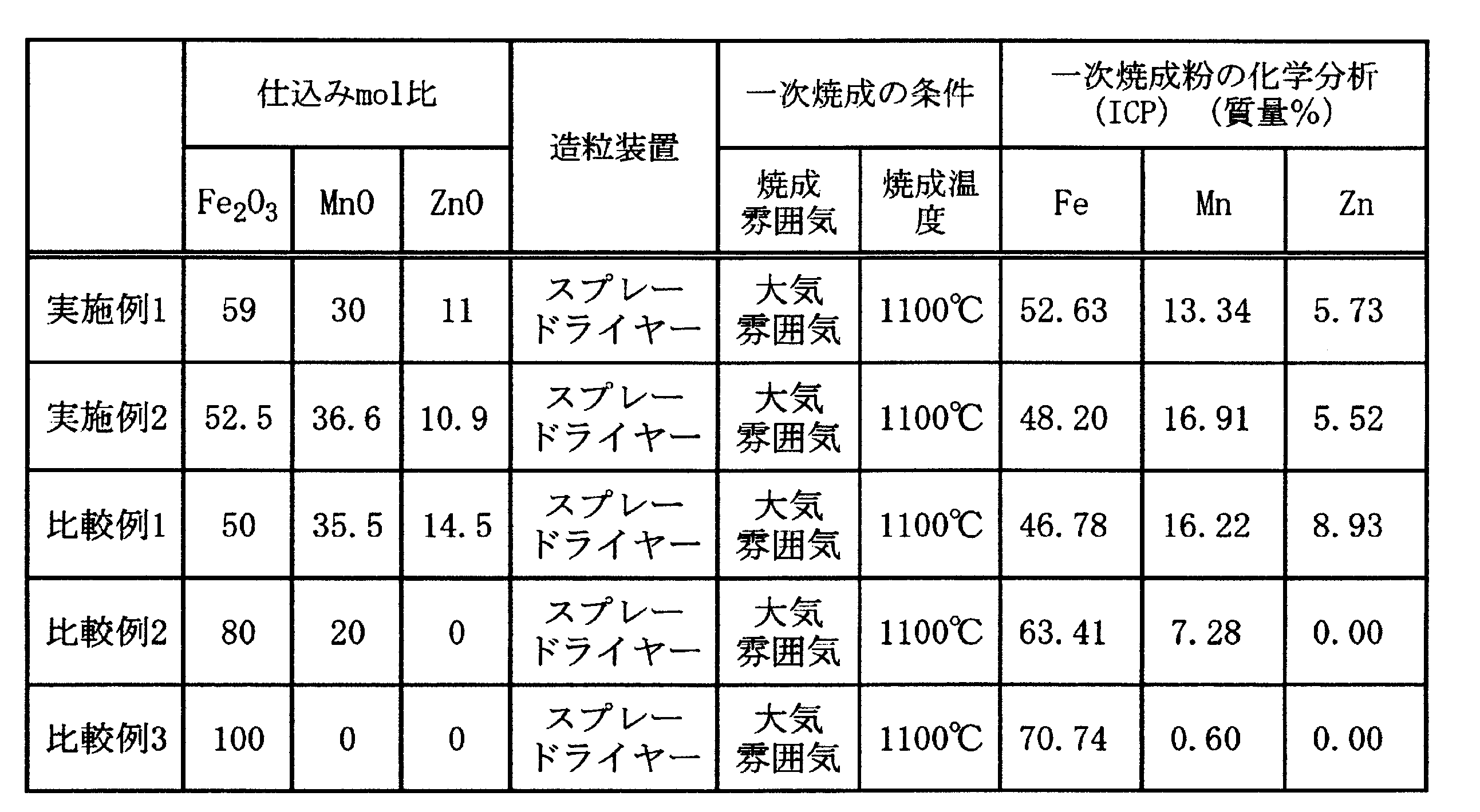


図1及び図2Aから、実施例1のフェライト粒子は多面体状の粒子形状を備えることが分かる。図2Bから、フェライト粒子の内部に結晶粒界が観察されないことから、実施例1のフェライト粒子は単結晶体であることが分かる。また、図3からも、実施例1のフェライト粒子は単結晶体であることが分かる。そして、実施例2のフェライト粒子について、実施例1と同様に観察したところ、実施例1のフェライト粒子と同様の粒子形状及び結晶形態を備えることが判明した。
本出願は、2017年9月29日出願の日本特許出願(特願2017-190071)に基づくものであり、その内容はここに参照として取り込まれる。
Claims (6)
- Feを44~60質量%、Mnを10~16質量%、Znを1~11質量%含有するMn-Zn系フェライト粒子であって、
当該フェライト粒子は、平均粒径が1~2000nmの単結晶体であり、且つ、平均球形度が0.85以上0.95未満であって多面体状の粒子形状を備えることを特徴とするMn-Zn系フェライト粒子。 - 前記フェライト粒子の飽和磁化が50~65Am2/kgである請求項1に記載のMn-Zn系フェライト粒子。
- 前記フェライト粒子の平均粒径が5~1500nmである請求項1又は請求項2に記載のMn-Zn系フェライト粒子。
- 請求項1から請求項3のいずれか一項に記載のMn-Zn系フェライト粒子を含有することを特徴とする樹脂成形体。
- 請求項1から請求項3のいずれか一項に記載のMn-Zn系フェライト粒子と、軟磁性粉末とを含むことを特徴とする軟磁性混合粉。
- 請求項5に記載の軟磁性混合粉を含むことを特徴とする磁芯。
Priority Applications (5)
| Application Number | Priority Date | Filing Date | Title |
|---|---|---|---|
| US16/650,647 US11651881B2 (en) | 2017-09-29 | 2018-09-27 | Mn—Zn ferrite particles, resin molded body, soft magnetic mixed powder, and magnetic core |
| CN201880062497.6A CN111164050B (zh) | 2017-09-29 | 2018-09-27 | Mn-Zn系铁氧体颗粒、树脂成形体、软磁性混合粉及磁芯 |
| JP2019545654A JP7217973B2 (ja) | 2017-09-29 | 2018-09-27 | Mn-Zn系フェライト粒子、樹脂成形体、軟磁性混合粉及び磁芯 |
| EP18861772.4A EP3689825A4 (en) | 2017-09-29 | 2018-09-27 | MN-ZN FERRITE PARTICLES, RESIN SHAPED BODIES, SOFT MAGNETIC MIXED POWDER AND MAGNETIC CORE |
| KR1020207008435A KR102547326B1 (ko) | 2017-09-29 | 2018-09-27 | Mn-Zn계 페라이트 입자, 수지 성형체, 연자성 혼합 분말 및 자심 |
Applications Claiming Priority (2)
| Application Number | Priority Date | Filing Date | Title |
|---|---|---|---|
| JP2017190071 | 2017-09-29 | ||
| JP2017-190071 | 2017-09-29 |
Publications (1)
| Publication Number | Publication Date |
|---|---|
| WO2019065923A1 true WO2019065923A1 (ja) | 2019-04-04 |
Family
ID=65903317
Family Applications (1)
| Application Number | Title | Priority Date | Filing Date |
|---|---|---|---|
| PCT/JP2018/036141 Ceased WO2019065923A1 (ja) | 2017-09-29 | 2018-09-27 | Mn-Zn系フェライト粒子、樹脂成形体、軟磁性混合粉及び磁芯 |
Country Status (6)
| Country | Link |
|---|---|
| US (1) | US11651881B2 (ja) |
| EP (1) | EP3689825A4 (ja) |
| JP (1) | JP7217973B2 (ja) |
| KR (1) | KR102547326B1 (ja) |
| CN (1) | CN111164050B (ja) |
| WO (1) | WO2019065923A1 (ja) |
Cited By (7)
| Publication number | Priority date | Publication date | Assignee | Title |
|---|---|---|---|---|
| JPWO2021210477A1 (ja) * | 2020-04-17 | 2021-10-21 | ||
| JP2022109787A (ja) * | 2021-01-15 | 2022-07-28 | パナソニックIpマネジメント株式会社 | 磁性樹脂組成物、及び成形体 |
| WO2022209640A1 (ja) * | 2021-03-31 | 2022-10-06 | パウダーテック株式会社 | フェライト粉末、フェライト樹脂複合材料並びに電磁波シールド材、電子材料又は電子部品 |
| WO2023149454A1 (ja) * | 2022-02-07 | 2023-08-10 | パナソニックIpマネジメント株式会社 | 磁性樹脂組成物、磁性シート、及びインダクタ部品 |
| JP2023131361A (ja) * | 2022-03-09 | 2023-09-22 | Tdk株式会社 | コイル装置 |
| JP2024080835A (ja) * | 2022-12-05 | 2024-06-17 | 日本特殊陶業株式会社 | 電波吸収体 |
| WO2024204070A1 (ja) * | 2023-03-31 | 2024-10-03 | 味の素株式会社 | 回路基板の製造方法及び樹脂組成物 |
Families Citing this family (1)
| Publication number | Priority date | Publication date | Assignee | Title |
|---|---|---|---|---|
| US12112876B2 (en) * | 2018-11-16 | 2024-10-08 | Lg Innotek Co., Ltd. | Magnetic core using composite material |
Citations (8)
| Publication number | Priority date | Publication date | Assignee | Title |
|---|---|---|---|---|
| JPS4919077B1 (ja) * | 1970-12-04 | 1974-05-15 | ||
| JPH06325918A (ja) * | 1993-05-11 | 1994-11-25 | Nippon Steel Corp | フェライト磁性材料 |
| JP2002025816A (ja) | 2000-07-07 | 2002-01-25 | Shoei Chem Ind Co | 単結晶フェライト微粉末 |
| JP2005112665A (ja) * | 2003-10-07 | 2005-04-28 | Tdk Corp | 単結晶セラミックス粒子、球状酸化物粉末 |
| JP2005240138A (ja) * | 2004-02-27 | 2005-09-08 | Tdk Corp | 軟磁性金属粉末、複合絶縁磁性組成物及び電子部品 |
| JP2010010529A (ja) * | 2008-06-30 | 2010-01-14 | Mitsui Chemicals Inc | 磁気コアおよび磁気コアの製造方法 |
| JP2011114321A (ja) * | 2009-11-30 | 2011-06-09 | Dowa Electronics Materials Co Ltd | 軟磁性粒子 |
| JP2016092403A (ja) | 2014-11-04 | 2016-05-23 | サムソン エレクトロ−メカニックス カンパニーリミテッド. | 軟磁性金属複合体 |
Family Cites Families (17)
| Publication number | Priority date | Publication date | Assignee | Title |
|---|---|---|---|---|
| NL150315B (nl) | 1972-04-18 | 1976-08-16 | Conrardus Hubertus Aquarius | Inrichting voor het vervaardigen van lolly's. |
| US4372865A (en) * | 1980-09-26 | 1983-02-08 | Spang Industries, Inc. | Carbonate/hydroxide coprecipitation process |
| DE3273566D1 (en) * | 1981-08-19 | 1986-11-06 | Basf Ag | Process for the preparation of finely divided ferrite powder |
| US4698289A (en) * | 1984-08-15 | 1987-10-06 | Halomet Inc. | Process for making ferrite spherical particulate toner core from raw fly ash |
| JPH07225910A (ja) * | 1994-02-08 | 1995-08-22 | Mitsubishi Electric Corp | 磁気ヘッドの製造方法 |
| TWI291936B (ja) * | 2001-05-31 | 2008-01-01 | Tdk Corp | |
| JP2004247370A (ja) * | 2003-02-12 | 2004-09-02 | Minebea Co Ltd | MnZnフェライト |
| JP2011227452A (ja) * | 2010-03-30 | 2011-11-10 | Powdertech Co Ltd | 電子写真現像剤用フェライトキャリア芯材、フェライトキャリア及びこれらの製造方法、並びに該フェライトキャリアを用いた電子写真現像剤 |
| JP5488910B2 (ja) * | 2010-06-30 | 2014-05-14 | パウダーテック株式会社 | 電子写真現像剤用フェライトキャリア芯材及びフェライトキャリア、並びに該フェライトキャリアを用いた電子写真現像剤 |
| JP5818380B2 (ja) | 2013-11-25 | 2015-11-18 | Dowaエレクトロニクス株式会社 | フェライト粒子並びにそれを用いた電子写真現像用キャリア及び電子写真用現像剤 |
| US10325706B2 (en) * | 2014-09-17 | 2019-06-18 | Autonetworks Technologies, Ltd. | Composite material, magnetic component, and reactor |
| EP3196168B1 (en) * | 2014-09-19 | 2023-08-02 | Powdertech Co., Ltd. | Nanosized spherical ferrite particles and method for manufacturing same |
| EP3202717B1 (en) * | 2014-10-01 | 2023-12-20 | Toda Kogyo Corp. | Ferrite particle powder for bonded magnets, resin composition for bonded magnets, and molded article using same |
| JP6547229B2 (ja) * | 2016-03-31 | 2019-07-24 | パウダーテック株式会社 | フェライト粒子、樹脂組成物及び樹脂フィルム |
| CN106229104A (zh) | 2016-08-31 | 2016-12-14 | 北京康普锡威科技有限公司 | 一种软磁复合粉末及其磁粉芯制备方法 |
| JP6393944B2 (ja) * | 2016-09-30 | 2018-09-26 | パウダーテック株式会社 | Ni−Zn−Cu系フェライト粒子、樹脂組成物及び樹脂成形体 |
| CN111788256A (zh) * | 2018-04-02 | 2020-10-16 | 松下知识产权经营株式会社 | 树脂粉末、密封材料、电子部件以及树脂粉末制造方法 |
-
2018
- 2018-09-27 JP JP2019545654A patent/JP7217973B2/ja active Active
- 2018-09-27 CN CN201880062497.6A patent/CN111164050B/zh active Active
- 2018-09-27 KR KR1020207008435A patent/KR102547326B1/ko active Active
- 2018-09-27 WO PCT/JP2018/036141 patent/WO2019065923A1/ja not_active Ceased
- 2018-09-27 EP EP18861772.4A patent/EP3689825A4/en active Pending
- 2018-09-27 US US16/650,647 patent/US11651881B2/en active Active
Patent Citations (8)
| Publication number | Priority date | Publication date | Assignee | Title |
|---|---|---|---|---|
| JPS4919077B1 (ja) * | 1970-12-04 | 1974-05-15 | ||
| JPH06325918A (ja) * | 1993-05-11 | 1994-11-25 | Nippon Steel Corp | フェライト磁性材料 |
| JP2002025816A (ja) | 2000-07-07 | 2002-01-25 | Shoei Chem Ind Co | 単結晶フェライト微粉末 |
| JP2005112665A (ja) * | 2003-10-07 | 2005-04-28 | Tdk Corp | 単結晶セラミックス粒子、球状酸化物粉末 |
| JP2005240138A (ja) * | 2004-02-27 | 2005-09-08 | Tdk Corp | 軟磁性金属粉末、複合絶縁磁性組成物及び電子部品 |
| JP2010010529A (ja) * | 2008-06-30 | 2010-01-14 | Mitsui Chemicals Inc | 磁気コアおよび磁気コアの製造方法 |
| JP2011114321A (ja) * | 2009-11-30 | 2011-06-09 | Dowa Electronics Materials Co Ltd | 軟磁性粒子 |
| JP2016092403A (ja) | 2014-11-04 | 2016-05-23 | サムソン エレクトロ−メカニックス カンパニーリミテッド. | 軟磁性金属複合体 |
Non-Patent Citations (1)
| Title |
|---|
| See also references of EP3689825A4 |
Cited By (12)
| Publication number | Priority date | Publication date | Assignee | Title |
|---|---|---|---|---|
| JPWO2021210477A1 (ja) * | 2020-04-17 | 2021-10-21 | ||
| CN115398569A (zh) * | 2020-04-17 | 2022-11-25 | 富士胶片株式会社 | 磁性树脂组合物、固化物及电子零件 |
| JP7477603B2 (ja) | 2020-04-17 | 2024-05-01 | 富士フイルム株式会社 | 磁性樹脂組成物、硬化物および電子部品 |
| JP2022109787A (ja) * | 2021-01-15 | 2022-07-28 | パナソニックIpマネジメント株式会社 | 磁性樹脂組成物、及び成形体 |
| WO2022209640A1 (ja) * | 2021-03-31 | 2022-10-06 | パウダーテック株式会社 | フェライト粉末、フェライト樹脂複合材料並びに電磁波シールド材、電子材料又は電子部品 |
| JPWO2022209640A1 (ja) * | 2021-03-31 | 2022-10-06 | ||
| JP7335670B2 (ja) | 2021-03-31 | 2023-08-30 | パウダーテック株式会社 | フェライト粉末、フェライト樹脂複合材料並びに電磁波シールド材、電子材料又は電子部品 |
| WO2023149454A1 (ja) * | 2022-02-07 | 2023-08-10 | パナソニックIpマネジメント株式会社 | 磁性樹脂組成物、磁性シート、及びインダクタ部品 |
| JP2023131361A (ja) * | 2022-03-09 | 2023-09-22 | Tdk株式会社 | コイル装置 |
| JP2024080835A (ja) * | 2022-12-05 | 2024-06-17 | 日本特殊陶業株式会社 | 電波吸収体 |
| JP7653964B2 (ja) | 2022-12-05 | 2025-03-31 | 日本特殊陶業株式会社 | 電波吸収体 |
| WO2024204070A1 (ja) * | 2023-03-31 | 2024-10-03 | 味の素株式会社 | 回路基板の製造方法及び樹脂組成物 |
Also Published As
| Publication number | Publication date |
|---|---|
| US11651881B2 (en) | 2023-05-16 |
| KR20200064070A (ko) | 2020-06-05 |
| CN111164050A (zh) | 2020-05-15 |
| EP3689825A1 (en) | 2020-08-05 |
| CN111164050B (zh) | 2023-05-30 |
| JP7217973B2 (ja) | 2023-02-06 |
| US20200251263A1 (en) | 2020-08-06 |
| JPWO2019065923A1 (ja) | 2020-09-10 |
| EP3689825A4 (en) | 2021-05-26 |
| KR102547326B1 (ko) | 2023-06-22 |
Similar Documents
| Publication | Publication Date | Title |
|---|---|---|
| JP7217973B2 (ja) | Mn-Zn系フェライト粒子、樹脂成形体、軟磁性混合粉及び磁芯 | |
| JP3542319B2 (ja) | 単結晶フェライト微粉末 | |
| JP7068703B2 (ja) | フェライト粒子、樹脂組成物及び電磁波シールド材料 | |
| KR20140031220A (ko) | 강자성 입자 분말의 제조 방법, 이방성 자석, 본드 자석 및 압분 자석 | |
| KR20140035019A (ko) | 염 함유 페라이트 자성체 및 그 제조방법 | |
| JP2020161726A (ja) | 高周波用複合磁性材料 | |
| JP7335670B2 (ja) | フェライト粉末、フェライト樹脂複合材料並びに電磁波シールド材、電子材料又は電子部品 | |
| US10825593B2 (en) | Ni—Zn—Cu ferrite particle, resin composition, and resin molding | |
| JP7486774B2 (ja) | フェライト粉末及びその製造方法 | |
| JP7687975B2 (ja) | 金属粉末 | |
| WO2021070871A1 (ja) | フェライト粉末、フェライト樹脂複合材料並びに電磁波シールド材、電子材料又は電子部品 | |
| JP7576881B2 (ja) | 高周波用磁性材料とその製造法 | |
| JP7839558B2 (ja) | フェライト粉末 | |
| JPWO2022202760A5 (ja) | ||
| CN115003633A (zh) | 铁氧体粉末及其制造方法 | |
| US20250299855A1 (en) | Soft Magnetic Powder, Dust Core, Magnetic Element, And Electronic Device | |
| US20240186038A1 (en) | Soft magnetic powder, metal powder, dust core, magnetic element, and electronic device | |
| WO2021200746A1 (ja) | フェライト粉末、フェライト樹脂組成物、樹脂成型体、電子部品、電子機器又は電子機器筐体 | |
| TW202219291A (zh) | 軟磁性合金粉末及其壓粉體及彼等之製造方法 | |
| Choi | Structure Analysis and Magnetic Properties of Nano-Sized Nb x Cu y Zn1− x− y Fe2O4 Powders Formed by Self-Propagating High-Temperature Synthesis and Ultrasonic Agitation Method | |
| Kumar et al. | Studies on Mn (ZnxFe2O4 Nanoparticles Synthesized by Co-Precipitation Method |
Legal Events
| Date | Code | Title | Description |
|---|---|---|---|
| 121 | Ep: the epo has been informed by wipo that ep was designated in this application |
Ref document number: 18861772 Country of ref document: EP Kind code of ref document: A1 |
|
| ENP | Entry into the national phase |
Ref document number: 2019545654 Country of ref document: JP Kind code of ref document: A |
|
| ENP | Entry into the national phase |
Ref document number: 20207008435 Country of ref document: KR Kind code of ref document: A |
|
| NENP | Non-entry into the national phase |
Ref country code: DE |
|
| ENP | Entry into the national phase |
Ref document number: 2018861772 Country of ref document: EP Effective date: 20200429 |