WO2019069341A1 - シート部材搬送装置及びインクジェット記録装置 - Google Patents
シート部材搬送装置及びインクジェット記録装置 Download PDFInfo
- Publication number
- WO2019069341A1 WO2019069341A1 PCT/JP2017/035764 JP2017035764W WO2019069341A1 WO 2019069341 A1 WO2019069341 A1 WO 2019069341A1 JP 2017035764 W JP2017035764 W JP 2017035764W WO 2019069341 A1 WO2019069341 A1 WO 2019069341A1
- Authority
- WO
- WIPO (PCT)
- Prior art keywords
- transport
- region
- mounting surface
- conveyance
- unit
- Prior art date
- Legal status (The legal status is an assumption and is not a legal conclusion. Google has not performed a legal analysis and makes no representation as to the accuracy of the status listed.)
- Ceased
Links
Images


Classifications
-
- B—PERFORMING OPERATIONS; TRANSPORTING
- B41—PRINTING; LINING MACHINES; TYPEWRITERS; STAMPS
- B41J—TYPEWRITERS; SELECTIVE PRINTING MECHANISMS, i.e. MECHANISMS PRINTING OTHERWISE THAN FROM A FORME; CORRECTION OF TYPOGRAPHICAL ERRORS
- B41J11/00—Devices or arrangements of selective printing mechanisms, e.g. ink-jet printers or thermal printers, for supporting or handling copy material in sheet or web form
- B41J11/007—Conveyor belts or like feeding devices
-
- B—PERFORMING OPERATIONS; TRANSPORTING
- B41—PRINTING; LINING MACHINES; TYPEWRITERS; STAMPS
- B41J—TYPEWRITERS; SELECTIVE PRINTING MECHANISMS, i.e. MECHANISMS PRINTING OTHERWISE THAN FROM A FORME; CORRECTION OF TYPOGRAPHICAL ERRORS
- B41J11/00—Devices or arrangements of selective printing mechanisms, e.g. ink-jet printers or thermal printers, for supporting or handling copy material in sheet or web form
- B41J11/0085—Using suction for maintaining printing material flat
-
- B—PERFORMING OPERATIONS; TRANSPORTING
- B41—PRINTING; LINING MACHINES; TYPEWRITERS; STAMPS
- B41J—TYPEWRITERS; SELECTIVE PRINTING MECHANISMS, i.e. MECHANISMS PRINTING OTHERWISE THAN FROM A FORME; CORRECTION OF TYPOGRAPHICAL ERRORS
- B41J13/00—Devices or arrangements of selective printing mechanisms, e.g. ink-jet printers or thermal printers, specially adapted for supporting or handling copy material in short lengths, e.g. sheets
- B41J13/08—Conveyor bands or like feeding devices
-
- B—PERFORMING OPERATIONS; TRANSPORTING
- B41—PRINTING; LINING MACHINES; TYPEWRITERS; STAMPS
- B41J—TYPEWRITERS; SELECTIVE PRINTING MECHANISMS, i.e. MECHANISMS PRINTING OTHERWISE THAN FROM A FORME; CORRECTION OF TYPOGRAPHICAL ERRORS
- B41J2/00—Typewriters or selective printing mechanisms characterised by the printing or marking process for which they are designed
- B41J2/005—Typewriters or selective printing mechanisms characterised by the printing or marking process for which they are designed characterised by bringing liquid or particles selectively into contact with a printing material
- B41J2/01—Ink jet
Definitions
- the present invention relates to a sheet member conveyance device and an inkjet recording device.
- an inkjet recording apparatus that discharges ink to a sheet member such as a sheet or a resin sheet to record an image on the sheet member.
- a sheet member conveying apparatus is widely used, in which the sheet member is placed and conveyed on the mounting surface of a conveying member (for example, a conveying belt moving around a predetermined circumferential path) which moves a predetermined movement path It is done.
- the sheet member is attracted to the mounting surface by sucking air from the side opposite to the mounting surface of the conveying member through the plurality of air holes provided in the conveying member.
- a flat plate-like ventilation member for example, a porous body
- the mounting surface of the conveying member and the flatness of the sheet member on the mounting surface there is known a technique in which a sheet member is adsorbed to a mounting surface while securing the (see, for example, Patent Document 1 and Patent Document 2).
- various processes on the sheet member such as ink ejection can be accurately performed to record a high quality image.
- An object of the present invention is to provide a sheet conveying apparatus and an inkjet recording apparatus capable of more reliably adsorbing a sheet to a mounting surface.
- the invention of the sheet member conveying apparatus is: A transport unit configured to transport the sheet member by moving the transport member on which the sheet member is placed on the placement surface in a predetermined transport direction; A ventilation member provided on the opposite side to the mounting surface of the conveyance member along the movement path of the conveyance member in the conveyance direction, and capable of ventilating in a direction perpendicular to the mounting surface; It is provided along the movement path in the range including the area which overlaps with the ventilation member when viewed from the direction perpendicular to the mounting surface on the opposite side to the mounting surface of the conveying member, and the conveying member has An air chamber capable of ventilating air through the pores to the mounting surface side of the transport member; Air is sucked through the air chamber from the side opposite to the mounting surface side of the transport member, and suction is performed to adsorb the sheet member mounted on the mounting surface of the transport member onto the mounting surface.
- the air chamber is provided in a first area within a predetermined range in the conveyance direction and on the downstream side of the first area in the conveyance direction, and is ventilated in an air passage passing through the air hole and the air vent member. Including two regions,
- the pressure loss in the ventilation path from the mounting surface side of the transport member to the first region when the air in the air chamber is sucked by the suction unit is the pressure loss of the transfer member in the ventilating portion. It is provided so as to be smaller than the pressure loss in the ventilation path from the mounting surface side to the second region.
- the invention according to claim 2 is the sheet member conveying apparatus according to claim 1,
- the ventilation member is provided in a range overlapping with the second region when viewed from a direction perpendicular to the mounting surface,
- the first region is a region where ventilation is performed in a ventilation path not passing through the ventilation member.
- the invention according to claim 3 is the sheet member conveying apparatus according to claim 1.
- the ventilation member is provided in an area overlapping with the first area and the second area when viewed from a direction perpendicular to the mounting surface.
- the first region is a region where ventilation is performed in a ventilation path passing through the ventilation member.
- the invention according to claim 4 is the sheet member conveying apparatus according to claim 3.
- the ventilation member has a flat plate shape in a portion overlapping with the first region when viewed in a direction perpendicular to the mounting surface, and a portion overlapping the second region in a direction perpendicular to the mounting surface.
- the thickness in the direction perpendicular to the mounting surface in the portion overlapping the first region is smaller than the thickness in the direction perpendicular to the mounting surface in the portion overlapping the second region.
- the invention according to claim 5 is the sheet member conveying apparatus according to any one of claims 1 to 4.
- the ventilation member is a porous body.
- the invention according to claim 6 is the sheet member conveying apparatus according to claim 3 or 4
- the ventilation member is a porous body having pores, and the opening ratio of the pores in a cross section parallel to the mounting surface in a portion overlapping the first region when viewed from the direction perpendicular to the mounting surface. Is larger than the aperture ratio of the pores in a cross section parallel to the mounting surface in a portion overlapping the second region when viewed in the direction perpendicular to the mounting surface.
- the invention according to claim 7 is the sheet member conveying apparatus according to any one of claims 1 to 4,
- the ventilation member is a plate member provided with a through hole penetrating in a direction perpendicular to the mounting surface.
- the invention according to claim 8 is the sheet member conveying apparatus according to claim 3 or 4.
- the ventilation member is a plate provided with a through hole penetrating in a direction perpendicular to the mounting surface, and the mounting surface in a portion overlapping with the first region when viewed from the direction perpendicular to the mounting surface.
- the aperture ratio of the through hole in the parallel cross section is higher than the aperture ratio of the through hole in the cross section parallel to the placing surface in the portion overlapping the second region when viewed from the direction perpendicular to the placing surface. large.
- the invention according to claim 9 is the sheet member conveying apparatus according to any one of claims 1 to 8,
- the air chamber includes the first region within a predetermined range from the upstream end of the air chamber in the transport direction, and the second region excluding the first region.
- the invention according to claim 10 is the sheet member conveying apparatus according to claim 9.
- the air chamber has a first sub air chamber forming the first region, and a second sub air chamber forming the second region and not directly ventilating with the first sub air chamber,
- the suction unit sucks air through the first sub air chamber and the second sub air chamber.
- the invention according to claim 11 is the sheet member conveying apparatus according to claim 10.
- the suction unit has a first suction fan that sucks air through the first sub air chamber, and a second suction fan that sucks air through the second sub air chamber.
- the invention according to claim 12 is the sheet member conveying apparatus according to any one of claims 1 to 11,
- the transport member is an annular transport belt whose outer peripheral surface forms the mounting surface described above,
- the transport unit moves the transport belt along a predetermined circulation path.
- the ventilation member and the air chamber are provided on the inner circumferential surface side of the conveyance belt.
- the invention according to claim 13 is the sheet member conveying apparatus according to any one of claims 1 to 9,
- the conveying member includes an annular first conveying belt whose outer peripheral surface forms the mounting surface, and an annular second conveying belt provided on the downstream side of the first conveying belt and whose outer peripheral surface forms the mounting surface.
- the conveyance unit transfers the sheet member between the first conveyance belt and the second conveyance belt by moving the first conveyance belt and the second conveyance belt along predetermined circulation paths. Conveying the sheet member in the conveying direction;
- the ventilation member is provided on the inner circumferential surface side of the second conveyance belt.
- the air chamber is provided on the inner circumferential surface side of the first conveyance belt and includes the upstream air chamber including at least a part of the first region, and the inner circumferential surface side of the second conveyance belt. It is divided into the downstream air chamber containing the 2nd field.
- the invention according to claim 14 is the sheet member conveying apparatus according to claim 13.
- the transport unit rotates at least one of the plurality of first transport rollers on which the first transport belt is spanned to move the first transport belt, and a plurality of the second transport belts are spanned Rotating at least one of the second transport rollers to move the second transport belt, Among the plurality of first conveyance rollers, the diameter of the first conveyance roller closest to the rear end of the conveyance path of the sheet member by the first conveyance belt is the second conveyance belt among the plurality of second conveyance rollers Smaller than the diameter of the second transport roller closest to the leading end of the transport path of the sheet member.
- an inkjet recording apparatus is: An ink discharge unit that discharges ink from a nozzle to a sheet member;
- the sheet member transport apparatus according to any one of claims 1 to 14, which transports a sheet member on which ink ejected from the nozzles of the ink ejection unit has landed. Equipped with
- the invention according to claim 16 is the inkjet recording apparatus according to claim 15.
- the ink ejection unit ejects from the nozzle an ink which is cured in response to application of a predetermined energy.
- the inkjet recording device is Energy provided to the side opposite to the second region of the air chamber with respect to the transport member, energy for applying the predetermined energy to the ink landed on the sheet member adsorbed to the mounting surface.
- the provision unit is provided.
- the invention according to claim 17 is the inkjet recording apparatus according to claim 15 or 16.
- the transport portion is a first transport portion provided with the ventilation member such that the vent hole forms a vent path to the first region and the second region, and the upstream side of the first transport portion in the transport direction
- a second conveyance unit for conveying the sheet member in the conveyance direction on the side, and conveying the sheet member in the conveyance direction while delivering the sheet member between the first conveyance unit and the second conveyance unit;
- the ink discharge unit discharges ink from the nozzle to a sheet member being conveyed by the second conveyance unit.
- the sheet member can be more reliably attracted to the mounting surface.
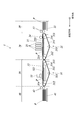
- FIG. 1 is a view showing a schematic configuration of an inkjet recording apparatus.
- FIG. 2 is a block diagram showing the main functional configuration of the inkjet recording apparatus. It is the top view which looked at the support attraction
- FIG. 3B is a cross-sectional view taken along the line AA of FIG. 3A. It is a figure explaining the suction characteristic of direct suction and ventilation member intervention suction. It is a sectional view showing the composition of the support suction part concerning modification 1. As shown in FIG. It is a sectional view showing the composition of the support suction part concerning modification 1. As shown in FIG. FIG. 10 is a cross-sectional view showing a configuration of a support suction unit according to a modification 2; FIG.
- FIG. 10 is a cross-sectional view showing a configuration of a support suction unit according to a modification 2;
- FIG. 10 is a cross-sectional view showing a configuration of a support suction unit according to a modification 2;
- FIG. 13 is a cross-sectional view showing a configuration of a support suction unit according to a third modification. It is a top view which shows the structure of the support attraction
- FIG. FIG. 13 is a view showing a schematic configuration of an ink jet recording apparatus according to a fifth modification.
- FIG. 13 is a view showing a schematic configuration of an ink jet recording apparatus according to a fifth modification.
- FIG. 1 is a view showing a schematic configuration of an inkjet recording apparatus 1 according to an embodiment of the present invention.
- the inkjet recording apparatus 1 includes a recording medium supply unit 10, an image recording unit 20, a fixing unit 30, a recording medium discharge unit 40, and the like.
- the recording medium supply unit 10 includes a placement tray 11, a medium delivery roller 12, and the like.
- the placement tray 11 is a plate-like member on which various individual recording media P (sheet members) such as paper, thick paper, corrugated board material and resin sheet can be stacked, and the recording media P on the placement tray is , And are sent to the image recording unit 20 in order from those placed at the top.
- the placement tray 11 is movable in the vertical direction, and is held at a position where the uppermost recording medium P is sent to the image recording unit 20 according to the total weight of the placed recording medium P and the like.
- the medium delivery roller 12 is a rotatable roller that holds the recording medium P from above and below, and delivers the recording medium P placed on the top of the placement tray 11 in the horizontal direction here.
- the medium delivery roller 12 is attached with a guide member for aligning the recording medium P at a predetermined position in the width direction perpendicular to the conveyance direction (left direction in FIG. 1) of the recording medium P.
- the recording medium P is sent to the image recording unit 20 in a state in which the direction alignment is performed.
- the image recording unit 20 discharges ink on the recording medium P delivered from the recording medium supply unit 10 to record an image, and sends out the recording medium P on which the ink is landed and the image is recorded to the fixing unit 30. .
- the image recording unit 20 discharges ink by the medium conveyance unit 21 (second conveyance unit) including the conveyance belt 211, the drive roller 212, the driven roller 213, the guide roller 214, and the tension roller 215, the support suction unit 22, Alternatively, a plurality of (in this case, four) head units 23 (ink ejection units), a pressing roller 24 and the like are provided.
- the conveyance belt 211 (conveyance member) of the medium conveyance unit 21 is an endless (annular) belt-like member, and a steel belt is used here.
- a steel belt for example, stainless steel such as SUS304 and SUS631 having a thickness of about 0.3 mm, or an aluminum alloy can be used.
- vents having the same opening shape that penetrates between the outer circumferential surface and the inner circumferential surface of the transport belt 211 specifically, a plurality of (multiple) circular holes having a diameter of about 0.5 mm
- the air vents are arranged at intervals of about 1.4 mm to provide an opening ratio of about 20%, and air can pass between the outer peripheral surface side and the inner peripheral surface side.
- the conveyance belt 211 is bridged between the drive roller 212 and the driven roller 213 (hereinafter collectively referred to as conveyance rollers 212 and 213), and is also referred to as an outer circumferential surface (hereinafter referred to as a placement surface) on which the recording medium P is placed. ) Are movably provided along the circumferential path around the transport rollers 212 and 213. That is, the transport belt 211 rotates around the route around the transport rollers 212 and 213 according to the speed and direction of rotation by the drive roller 212 rotating according to the rotation drive operation by the transport motor 65 (FIG. 2) Do.
- the transport belt 211 circulates counterclockwise.
- the support suction unit 22 includes an inner circumferential surface of the conveyance belt 211 (a conveyance roller 212, and the like) in a range including a portion where the placement surface of the conveyance belt 211 faces the ink discharge surface of the head unit 23 in the conveyance section of the conveyance belt 211
- the surface on the side in contact with 213 is supported by a plane (here, a horizontal surface) (hereinafter referred to as a support surface).
- the support surface of the support suction unit 22 is formed by a flat plate-like ventilation member 223 made of a porous body (porous) having air permeability.
- the support suction unit 22 is conveyed by suctioning air from the inner peripheral surface side of the conveyance belt 211 via the ventilation hole of the conveyance belt 211 and the ventilation member 223 by the suction fan 62 (FIG. 2) (suction unit).
- the recording medium P mounted on the mounting surface of the belt 211 is attracted to the mounting surface.
- Guide rollers 214 are provided on the upstream side and the downstream side of the support suction unit 22 in the transport direction.
- the two guide rollers 214 support the inner circumferential surface of the conveyance belt 211 on both ends outside of the support surface of the support suction unit 22.
- the guide rollers 214 support the transport belt 211 at substantially the same height as the support surface of the support suction unit 22 and guide the moving operation of the transport belt 211 during the circumferential movement.
- the pressing roller 24 is a roller provided rotatably at a position facing the guide roller 214 on the upstream side across the transport belt 211.
- the pressing roller 24 lifts up from the conveyance belt 211 of the recording medium P delivered from the recording medium supply unit 10 on the upstream side with respect to the discharge direction of the ink with respect to the recording medium P with respect to the discharge direction.
- the conveyance belt 211 is pressed (pressed) with appropriate pressure and guided along the conveyance belt 211 so that curling and the like are suppressed and suctioned more reliably.
- the pressing roller 24 can be configured to have a variable distance from the conveyance surface of the conveyance belt 211 according to the thickness of the recording medium P to be conveyed.
- the tension roller 215 is a side where the outer peripheral surface does not face the head unit 23 between the two conveyance rollers 212 and 213 among the conveyance belts 211, that is, the way the conveyance belt 211 moves from the driving roller 212 to the driven roller 213 An appropriate tension is given by pressing the conveyance belt 211 from the side of the inner circumferential surface at the position of.
- the tension roller 215 can be set at two different positions in the width direction, for example, vertically at the both ends vertically, and the meandering caused by the uneven tension received by the transport belt 211 by the support suction portion 22 or the like After correction, the conveyance belt 211 and the recording medium P are normally moved in the conveyance direction.
- the head unit 23 is provided on the side opposite to the support suction unit 22 with respect to the conveyance belt 211.
- the surface of the head unit 23 facing the transport belt 211 is an ink discharge surface provided with an opening of a nozzle, and the head unit 23 is mounted on the loading surface of the transport belt 211 by the support suction unit 22.
- the ink is discharged onto the recording medium P which is sucked and conveyed, and is made to land.
- the head unit 23 has one or more recording heads 231 (FIG. 2) in which the nozzle openings are provided in a predetermined array and perform an operation related to ink ejection from the nozzle openings.
- the arrangement range in the width direction of the nozzles in the head unit 23 covers the recording range of the image in the width direction with respect to the recording medium P.
- the position of the head unit 23 is fixed at the time of recording an image, and the ink is sequentially discharged at predetermined intervals (intervals in the transport direction) at different positions in the transport direction according to the transport of the recording medium P. Record images by single pass method.
- the four head units 23 are respectively connected to ink tanks (not shown) of each color of cyan (C), magenta (M), yellow (Y) and black (K), and the ink of each color of CMYK is respectively Discharge.
- the image recording unit 20 may include a head unit 23 that discharges inks other than the four colors, for example, inks of respective colors such as orange, green, violet, red, blue, and white, and transparent ink.
- an ink which changes in phase between gel and sol is used as the ink ejected from the nozzles of the head unit 23, an ink which changes in phase between gel and sol is used.
- the gel is contained in a solid, and the sol is contained in a liquid.
- the ink that has become gelled by heating is discharged from the nozzles of the head unit 23, and the ink that has landed on the recording medium P is cooled rapidly so that the ink becomes gelled and the recording medium P Solidify on.
- an ink (curable material) having a property of being cured by irradiation with ultraviolet light is used.
- the ink those containing a photopolymerizable compound (monomer), a photopolymerization initiator and a colorant are used.
- the photopolymerizable compound is a compound which is polymerized by the progress of a polymerization reaction when irradiated with ultraviolet light. This polymerization cures the ink.
- the photopolymerization initiator is a compound for initiating the above-mentioned polymerization reaction.
- the colorant also contains a pigment or dye of the color according to the ink.
- the image recording unit 20 sends the recording medium P having the ink ejected from the head unit 23 to the fixing unit 30.
- the fixing unit 30 is provided on the downstream side of the image recording unit 20 in the transport direction of the recording medium P, and fixes the ink on the recording medium P delivered from the image recording unit 20.
- the fixing unit 30 includes a medium conveyance unit 31 (first conveyance unit) including a conveyance belt 311, a drive roller 312, a driven roller 313, a guide roller 314, and a tension roller 315, a support suction unit 32, and an ultraviolet irradiation unit 33 (energy). And the like.
- the configuration of the medium transport unit 31 is the same as the configuration of the medium transport unit 21 of the image recording unit 20.
- the configuration of the support suction unit 32 is an image in that the formation range of the ventilation member 323 of the porous body constituting the support surface is an area excluding a predetermined range from the end on the upstream side of the support suction unit 32 in the transport direction. This differs from the support suction unit 22 of the recording unit 20. As described later, according to the support suction unit 32 having such a configuration, even if the recording medium P is warped or the like, it can be reliably attracted to the placement surface of the conveyance belt 211. For this reason, in the fixing unit 30, no pressure roller is provided. The configuration of the support suction unit 32 will be described in detail later.
- the ultraviolet irradiation unit 33 irradiates ultraviolet rays to the irradiation range in the width direction of the conveyance belt 311 with respect to the recording medium P which is adsorbed and conveyed on the mounting surface of the conveyance belt 311 by the support suction unit 32. By doing this, the ink on the recording medium P (which has landed on the recording medium P) is cured and fixed. It is preferable that the ultraviolet light irradiated from the ultraviolet light irradiation unit 33 be irradiated on the recording medium P placed on the conveyance belt 311 without large unevenness (variation in intensity).
- the fixing unit 30 delivers the recording medium P on which the ink is fixed to the recording medium discharge unit 40.
- the recording medium discharge unit 40 holds and holds the recording medium P delivered from the fixing unit 30 until it is taken out by the user.
- the recording medium discharge unit 40 includes a discharge tray 41 and a guide roller 42, holds the recording medium P sent from the fixing unit 30 from above and below by the guide roller 42, conveys the recording medium P, and places the recording medium P on the discharge tray 41.
- the discharge tray 41 is set lower than the mounting surface so that the recording medium P can be delivered from the mounting surface of the transport belt 311, and may be movable up and down depending on the amount of the recording medium P mounted. .
- the inkjet recording apparatus 1 conveys the recording medium P by the plurality of medium conveyance units 21 and 31 while having the respective functional configurations of the inkjet recording apparatus 1 including the medium conveyance units 21 and 31, that is, image recording
- the unit 20 and the fixing unit 30 are configured to perform predetermined processing on the recording medium P, respectively.
- the ink can be ejected to a desired position on the recording medium P, particularly in the image recording unit 20.
- the configuration of the inkjet recording apparatus 1 is not limited to those described above.
- a heating unit for heating the recording medium P to a predetermined temperature, the recording medium P, and the like between the recording medium supply unit 10 and the image recording unit 20 Alternatively, a medium processing unit that performs surface modification processing such as corona processing may be provided.
- FIG. 2 is a block diagram showing the main functional configuration of the inkjet recording apparatus 1.
- the inkjet recording apparatus 1 includes a control unit 50, support suction units 22 and 32 having a suction control unit 61 and a suction fan 62, a head unit 23 having a head control unit 63 and a recording head 231, and a conveyance control unit 64.
- a transport motor 65, an input / output interface 66, a bus 67 and the like are provided.
- the suction control unit 61, the head control unit 63, and the transport control unit 64 may use the hardware configurations of the control unit 50 in combination, or a dedicated CPU, memory, logic circuit, etc. are separately prepared. Also good.
- the control unit 50 includes a CPU 51 (Central Processing Unit), a RAM 52 (Random Access Memory), a ROM 53 (Read Only Memory), and a storage unit 54.
- CPU 51 Central Processing Unit
- RAM 52 Random Access Memory
- ROM 53 Read Only Memory
- the CPU 51 reads various control programs and setting data stored in the ROM 53 and stores the read control programs and setting data in the RAM 52, and executes the programs to perform various arithmetic processing.
- the CPU 51 also controls the overall operation of the inkjet recording apparatus 1.
- the RAM 52 provides the CPU 51 with a working memory space, and stores temporary data.
- the RAM 52 may include non-volatile memory.
- the ROM 53 stores various control programs executed by the CPU 51, setting data, and the like. Note that instead of the ROM 53, a rewritable non-volatile memory such as an EEPROM (Electrically Erasable Programmable Read Only Memory) or a flash memory may be used.
- EEPROM Electrically Erasable Programmable Read Only Memory
- the storage unit 54 stores a print job (image recording command) input from the external device 2 through the input / output interface 66 and image data of an image to be recorded according to the print job.
- a hard disk drive (HDD) may be used as the storage unit 54, and a dynamic random access memory (DRAM) may be used in combination.
- DRAM dynamic random access memory
- the suction control unit 61 causes the suction fans 62 of the support suction units 22 and 32 to rotate at a rotational speed corresponding to a control signal from the control unit 50.
- the head control unit 63 outputs various control signals and image data to the head driving unit in the recording head 231 at an appropriate timing according to the control signal from the control unit 50, so that The ink is ejected from the opening.
- the transport control unit 64 separately controls the operation of the transport motor 65 attached to each of the medium delivery roller 12 and the drive rollers 212 and 312 based on the control signal supplied from the control unit 50 to rotate each roller. And transport the recording medium P at an appropriate speed.
- the input / output interface 66 mediates transmission and reception of data between the external device 2 and the control unit 50.
- the input / output interface 66 is configured of, for example, various serial interfaces, any of various parallel interfaces, or a combination thereof.
- the bus 67 is a path for transmitting and receiving signals between the control unit 50 and other components.
- the external device 2 is, for example, a personal computer, and supplies a print job, image data, and the like to the control unit 50 via the input / output interface 66.
- the medium conveyance units 21 and 31, the support suction units 22 and 32, the conveyance control unit 64, and the conveyance motor 65 constitute a sheet member conveyance apparatus.
- the medium transport units 21 and 31 constitute a transport unit.
- the present invention may be applied as the medium transport unit 31 alone constitutes the transport unit.
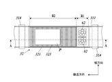
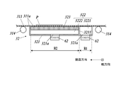
- FIG. 3A is a plan view of the support suction unit 32 as viewed from the ultraviolet irradiation unit 33 side.
- FIG. 3A in order to avoid becoming inconspicuous, each configuration is shown in a state of being transmitted through the transport belt 311, and the vent holes provided in the transport belt 311 are not shown.
- FIG. 3B is a cross-sectional view taken along the line AA of FIG. 3A.
- the support suction unit 32 is formed of a rectangular parallelepiped housing 321 whose one surface on the side of the conveyance belt 311 is open, and a plate-like porous body provided to close a part of the open surface of the housing 321. And a suction fan 62 for suctioning the air in the housing 321.
- An air chamber 322 is formed inside the housing 321 by covering the opened surface of the housing 321 with the transport belt 311. The suction fan 62 sucks the air in the air chamber 322 via a suction port 321 a opened in a part of the lower part of the housing 321.
- the housing 321 is made of a metal plate such as stainless steel or aluminum alloy having a thickness of about several millimeters.
- the length in the width direction and the conveyance direction of the housing 321 can be appropriately determined according to the size, the shape, and the like of the recording medium P to be conveyed by the medium conveyance unit 31.
- the suction port 321a is provided in the vicinity of the end on the upstream side in the transport direction of the bottom surface of the housing 321, but the position of the suction port 321a is not limited thereto.
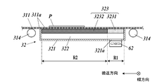
- the ventilation member 323 is a flat porous body with a thickness of about 5 mm fixed to the housing 321 along the open surface of the housing 321 (that is, along the movement path of the transport belt 311).
- the ventilation member 323 overlaps with the second region R2 excluding the first region R1 within a predetermined range from the end on the upstream side of the air chamber 322 in the conveyance direction when viewed from the direction perpendicular to the placement surface of the conveyance belt 311 It is provided. Therefore, in the first region R1 of the air chamber 322, the ventilation member 323 is not provided, and the upper surface in the housing 321 is open.
- the ventilation member 323 being arranged, in the first region R1 of the air chamber 322, the mounting surface of the conveyance belt 311 in the ventilation path which passes through the ventilation hole 311a of the conveyance belt 311 and does not pass through the ventilation member 323. Ventilation with the side is made. Further, in the second region R2 of the air chamber 322, ventilation is performed with the placement surface side of the conveyance belt 311 through the ventilation path passing through the ventilation holes 311a of the conveyance belt 311 and the ventilation member 323.
- the length in the transport direction of the first region R1 in the air chamber 322 is not particularly limited, but is set to be larger than the length at which the end portion Pc of the recording medium P may be warped. This is to ensure that the effect of attracting the end portion Pc of the recording medium P, which is warped, to the mounting surface, which will be described later, is sufficiently obtained.
- the length in the conveyance direction of the second region R2 in the air chamber 322 is, for example, a length in the conveyance direction of the recording medium P (a standard length among lengths of the recording medium P of a plurality of sizes to be conveyed). Or based on the maximum length etc.).
- the length in the transport direction of the second region R2 is greater than the maximum length of the recording medium P so that the entire recording medium P can be adsorbed on the second region R2.
- the length in the transport direction of the second region R2 is set to be larger than the length in the transport direction of the first region R1, and is about several to dozens of times the length in the transport direction of the first region R1.
- the ultraviolet irradiation part 33 is arrange
- the length in the width direction of the first area R1 and the second area R2 (that is, the length in the width direction of the housing 321 and the ventilation member 323) is the maximum value of the length in the width direction of the recording medium P to be conveyed. It is determined to be the above.
- a porous body which constitutes ventilation member 323 what was made to sinter resin particles, such as polyethylene resin, a fluoro-resin, polypropylene resin, etc. can be used, for example can be used.
- sinter resin particles such as polyethylene resin, a fluoro-resin, polypropylene resin, etc.
- the ventilation member 323 using the porous body of the material as described above has a small frictional resistance with the conveyance belt 311 and can suppress the damage of the conveyance belt 311, and the load of the conveyance motor 65. Can be reduced.
- the frictional resistance is small as described above, the generation of wear powder when the transport belt 311 slides on the ventilation member 323 can be suppressed to a very small extent.
- the suction fan 62 sucks and discharges the air in the air chamber 322 through the suction port 321 a with a suction force controlled by the suction control unit 61, and generates a negative pressure in the air chamber 322.
- air flows vertically downward through the vent holes 311a of the transport belt 311 toward the suction port 321a, It is discharged out of the housing 321.
- suction of air in the first region R1 not through the ventilation member 323 via the ventilation hole 311a will also be referred to as “direct suction”.
- vent-mediated suction In the second region R2, air flows vertically downward through the vent holes 311a of the transport belt 311 and the vent member 323, and then in the vicinity of the bottom surface of the housing 321 in the opposite direction to the transport direction toward the suction port 321a. The air flows and is discharged out of the housing 321.
- the suction of air through the vent holes 311 a and the vent member 323 in the second region R2 will also be referred to as “vent-mediated suction”.
- FIG. 4 is a view for explaining the suction characteristics of direct suction and ventilation member-mediated suction.
- FIG. 4 shows the relationship between the magnitude of the pulling force between direct suction and the ventilation member-mediated suction, and the relationship between the magnitude of the adsorption holding force.
- the attracting force is a force for attracting the recording medium P which is separated (floating) by a predetermined distance in the vertical direction from the placement surface of the conveyance belt 311, and the suction holding force is the placement surface Is a force that holds the attracted state by suppressing the peeling of the recording medium P adsorbed on the mounting surface from the mounting surface or the displacement of the recording medium P along the mounting surface.
- (Circle) in FIG.
- the vent hole 311a has a sufficiently large opening area and aperture ratio to the velocity and viscosity of air and a sufficiently small length (depth) in the vertical direction. The pressure drop at 311a is negligible.
- the pressure loss due to the various factors described above becomes larger than that of the ventilation hole 311a.
- the pressure loss in the ventilation path passing through the ventilation hole 311a and the ventilation member 323 in the ventilation member interposed suction in the second region R2 is the pressure loss in the ventilation path passing through the ventilation hole 311a in the direct suction of the first region R1. Rather, it becomes larger by the amount of passing through the ventilation member 323.
- the suction force in the first region R1 is larger in direct suction in the first region R1 than in the ventilation member-mediated suction in the second region R2.
- the support suction unit 32 even after the recording medium P is adsorbed to the mounting surface, the area around the recording medium P (both sides in the width direction of the recording medium P, and On the upstream side and the downstream side in the transport direction, air is sucked into the air chamber 322 from the mounting surface side of the transport belt 311.
- the first region R1 since the pressure loss of the air passing through the vent holes 311a of the transport belt 311 is very small, the region near the mounting surface of the transport belt 311 and the air chamber 322 There is less pressure difference between them. Therefore, due to the pressure difference, the action of attracting and holding the recording medium P on the placement surface is difficult to work, and the adsorption retention force is reduced.
- the ventilation member 323 having a large pressure loss has an effect of sealing the upper surface of the air chamber 322 with a certain degree of air tightness. Since the pressure difference between the mounting surface side of the transport belt 311 and the air chamber 322 is increased as described above, the recording medium P is strongly pressed against the mounting surface by the pressure difference. The adsorption holding power to adsorb and hold the mounting surface becomes large. From such a reason, as shown in FIG. 4, with regard to the adsorption holding power, the ventilation member-mediated suction in the second region R2 is larger than the direct suction in the first region R1.
- the first region R1 having a large attraction force is provided on the upstream side in the conveyance direction, so that the leading end of the recording medium P conveyed by the conveyance belt 311 and received on the first region R1.
- the end Pc on the side is warped (lifted from the mounting surface)
- the end Pc can be attracted to and attracted to the mounting surface by direct suction.
- the recording medium P adsorbed on the mounting surface is transported in the transport direction and reaches the second region R2
- the end portion Pc of the recording medium P is adsorbed because it is adsorbed by the strong adsorption holding force by the ventilation member interposed suction. It is possible to suppress the occurrence of the problem that the recording medium P is lifted again from the placement surface or the recording medium P is shifted on the placement surface.
- the rotational speed of the suction fan 62 is controlled to be equal to or higher than the minimum rotational speed at which the suction force capable of attracting can be obtained by pulling the Pc when the end Pc of the recording medium P is warped in the first region R1. It is controlled by the unit 50.
- the minimum rotational speed is the type (thickness, hardness, air permeability, etc.) of the recording medium P to be conveyed, the size of the assumed warpage (height from the placement surface), the width of the recording medium P It differs depending on various parameters such as the width in the direction (and hence the width of the portion of the first region R1 not covered by the recording medium P).
- the rotational speed of the suction fan 62 is, for example, predetermined corresponding to each combination of these parameters. Alternatively, it is possible to set the rotational speed at which the end Pc can be actually adsorbed by causing the end Pc of the recording medium P to be used to be warped and then conveyed one sheet.
- the ink ejected in the image recording unit 20 is in an uncured state. Therefore, when the end Pc of the recording medium P is warped, when the surface is pressed by the pressing roller, the uncured ink on the recording medium P contacts the pressing roller and the image is disturbed, or the pressing roller According to the configuration of the present embodiment, the recording medium P is adsorbed to the mounting surface without causing such a problem, and a position opposite to the ultraviolet irradiation unit 33 is generated. It can be transported.
- the ventilation member 223 is provided over the entire surface of the housing, and the ventilation member interposed suction is performed in the entire support suction unit 22. Further, when the end Pc of the recording medium P is warped, the end Pc is pressed against the placement surface by the pressing roller 24 and is attracted to the placement surface, as described above. This is because the ink is not discharged onto the recording medium P placed in the image recording unit 20, and the above-mentioned problems do not occur even if the surface of the recording medium P is directly pressed by the pressing roller 24. .
- the conveyance operation of the recording medium P and the recording operation of the image in the ink jet recording apparatus 1 of the present embodiment will be described.
- the recording operation of the image is started.
- a control signal is output from the suction control unit 61 to each suction fan 62 of the support suction units 22 and 32, and the rotation operation of each suction fan 62 is started at a predetermined rotation speed. Further, a control signal is output from the conveyance control unit 64 to the conveyance motor 65 attached to the medium delivery roller 12 and the drive rollers 212 and 312 respectively, and the recording medium supply unit 10 to the medium conveyance unit 21 of the image recording unit 20 The supply operation of the recording medium P and the conveyance operation of the recording medium P by the medium conveyance units 21 and 31 are started.
- the image data and control signal of the recording image are supplied from the head control unit 63 to each recording head 231 of the head unit 23 at an appropriate timing according to the conveyance position of the recording medium P by the medium conveyance unit 21. Then, the ink is ejected from the nozzles of the head unit 23 and an image is recorded on the recording medium P.
- the recording medium P is adsorbed and fixed to the mounting surface of the conveyance belt 211 by the strong adsorption holding force by the ventilation member-mediated suction in the support suction unit 22, floating or vibration of the recording medium P, etc. The occurrence of recording defects caused by
- the recording medium P from which the ink is discharged is delivered from the medium conveyance unit 21 of the image recording unit 20 to the medium conveyance unit 31 of the fixing unit 30.
- the recording medium P is effectively sucked by direct suction at a portion overlapping the first region R1 in the support suction unit 32. It is attracted to the placement unit and attracted. Then, the recording medium P is conveyed to a portion overlapping the second region R2, and the recording medium P is adsorbed and fixed to the mounting surface of the conveyance belt 211 with strong adsorption holding force by the ventilation member interposed suction.
- Curing and fixing of the ink by the ultraviolet irradiation unit 33 to the recording medium P in this state suppresses the occurrence of the fixing failure caused by the floating of the recording medium P, vibration, and the like.
- the recording medium P on which the ink is fixed is discharged to the recording medium discharge unit 40 in accordance with the conveyance operation of the medium conveyance unit 31.
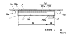
- FIGS. 5A and 5B are cross-sectional views showing the configuration of the support suction unit 32 according to the present modification.
- the ventilation member 323 is provided in a range overlapping with the entire air chamber 322 when viewed from the direction perpendicular to the mounting surface of the conveyance belt 311.
- the portion overlapping the first region R1 and the portion overlapping the second region R2 each have a flat plate shape, and the pressure loss in the portion overlapping the first region R1 is second
- the material, the shape, and the arrangement are provided so as to be smaller than the pressure loss in the portion overlapping the region R2.
- the ventilation member 323 is provided in a range overlapping the first region R1, and overlaps the first region 3231 made of a coarse porous body with pores and the second region R2 And a second portion 3232 which is provided in the range and which is a porous body having finer pores than the first portion 3231.
- the aperture ratio of the pores in a cross section parallel to the mounting surface of the first portion 3231 is greater than the aperture ratio of the pores in a cross section parallel to the mounting surface of the second portion 3232. It is getting bigger.
- the porosity of the porous body in the first portion 3231 is larger than the porosity of the porous body in the second portion 3232.
- the pressure loss in the portion overlapping the first region R1 of the ventilation member 323 is smaller than the pressure loss in the portion overlapping the second region R2.
- the ventilation member 323 has a mounting surface in the second portion 3234 in which the thickness in the direction perpendicular to the mounting surface in the first portion 3233 overlapping the first region R1 overlaps the second region R2. And the thickness in the perpendicular direction is smaller.
- the fineness (ie, the aperture ratio of the pores in the cross section parallel to the mounting surface) of the porous body in the first portion 3233 and the second portion 3234 is the same as that of the ventilation member 323 of the above embodiment. It is identical to the porous body used. Even with the configuration as shown in FIG. 5B, the pressure loss in the portion overlapping the first region R1 of the ventilation member 323 is smaller than the pressure loss in the portion overlapping the second region R2.
- the ventilation member-mediated suction is performed in both the first region R1 and the second region R2
- the pressure loss in the portion overlapping the first region R1 overlaps the second region R2
- the first region R1 is larger than the second region R2 with respect to the attraction force
- the second region R2 is more than the first region R1 with respect to the adsorption retention force, as in the above embodiment. Is larger. Therefore, also according to the configuration of the present modification, the recording medium P can be adsorbed with a high adsorption retention force in the second region R2 while the tip of the recording medium P is reliably adsorbed in the first region R1. Note that the fineness and thickness of the pores may be different between the first and second portions of the ventilation member 323.
- FIGS. 6A to 6C are cross-sectional views showing the configuration of the support suction unit 32 according to the present modification.
- the ventilation member 323 is formed by using a flat metal plate provided with a plurality of through holes 323a (323b) penetrating in a direction perpendicular to the mounting surface.
- the material of the ventilation member 323 is not limited to metal, and may be a material having sufficient strength to support the conveyance belt 311 and having little friction with the conveyance belt 311, such as resin.
- the ventilation member 323 in FIGS. 6A to 6C is also provided in such a material, shape, and arrangement that the pressure loss in the portion overlapping the first region R1 is smaller than the pressure loss in the portion overlapping the second region R2.
- the ventilation member 323 made of a metal plate is provided only in the area overlapping with the second area R2.
- direct suction is performed in the first region R1
- ventilation member-mediated suction is performed in the second region R2. Therefore, even with the configuration of FIG. 6A, the recording medium P can be adsorbed with high adsorption holding power in the second region R2 while the tip of the recording medium P is reliably adsorbed in the first region R1.
- the ventilation member 323 is provided in the range which overlaps with the whole air chamber 322.
- the opening area of each through hole 323a in the first portion 3235 overlapping the first region R1 is larger than the opening area of each through hole 323b in the second portion 3236 overlapping the second region R2.
- the aperture ratio of the through hole 323a in the cross section parallel to the mounting surface in the first portion 3231 is larger than the aperture ratio of the through hole 323b in the cross section parallel to the mounting surface in the second portion 3232.
- the pressure loss in the portion overlapping the first region R1 is also smaller than the pressure loss in the portion overlapping the second region R2 by the ventilation member 323 having such a configuration.
- the ventilation member 323 is provided in the range overlapping with the whole of the air chamber 322.
- the thickness in the direction perpendicular to the mounting surface in the first portion 3237 overlapping the first region R1 is greater than the thickness in the direction perpendicular to the mounting surface in the second portion 3238 overlapping the second region R2. Is also getting smaller.
- the opening area and the opening ratio of the through holes 323a in the first portion 3237 and the second portion 3238 are equal to each other.
- the pressure loss in the portion overlapping the first region R1 is also smaller than the pressure loss in the portion overlapping the second region R2 by the ventilation member 323 having such a configuration.
- the ventilation member-mediated suction is performed in both the first region R1 and the second region R2
- the pressure loss in the portion overlapping the first region R1 overlaps the second region R2
- the first region R1 is larger than the second region R2 with respect to the attraction force
- the second region R2 is more than the first region R1 with respect to the adsorption retention force, as in the above embodiment. Is larger. Therefore, also according to the configuration of the present modification, the recording medium P can be adsorbed with a high adsorption retention force in the second region R2 while the tip of the recording medium P is reliably adsorbed in the first region R1.
- both the opening area and the opening ratio of the through hole and the thickness may be made different.
- FIG. 7 is a cross-sectional view showing the configuration of the support suction unit 32 according to the present modification.
- the air chamber 322 is divided into a first sub air chamber 3221 forming a first region R1 and a second sub air chamber 3222 forming a second region R2.
- the first sub air chamber 3221 and the second sub air chamber 3222 are separated by the partition plate 3211 welded and fixed to the bottom and side of the housing 321 so that direct ventilation can not be achieved. It has become.
- the first sub air chamber 3221 and the second sub air chamber 3222 are provided with suction ports 321a, respectively, and internal air is sucked by the respective suction fans 62 (first suction fan, second suction fan). Ru.
- the rotation operation of each suction fan 62 is independently controlled by the suction control unit 61. According to the configuration of the present modification, the attraction force in the first region R1 and the adsorption holding force in the second region R2 can be adjusted independently.
- FIG. 8 is a plan view showing the configuration of the support suction unit 32 according to the present modification. Ventilation members 323 in the support suction portion 32 of FIG. 8 are provided in the vicinity of both ends in the width direction, and except for the second portion 3232 formed of a fine porous body with fine pores and the vicinity of both ends in the width direction. And a first portion 3231 which is provided and is made of a coarse porous body having pores larger than that of the second portion 3232.
- the pressure loss in the vicinity of both ends in the width direction in the second region R2 can be made larger than the pressure loss in the widthwise central portion.
- the sealing property of the ventilation member 323 at the outer portion in the width direction of the recording medium P is enhanced.
- the pressure difference between them and 322 can be more effectively increased, and the force for adsorbing and holding the recording medium P can be further increased.
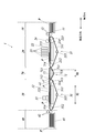
- FIG. 9 is a view showing a schematic configuration of the inkjet recording apparatus 1 according to the present modification.
- a delivery unit 70 is provided on the downstream side of the image recording unit 20 in the transport direction and on the upstream side of the fixing unit 30 in the transport direction.
- the delivery unit 70 adsorbs the recording medium P delivered from the image recording unit 20, conveys the recording medium P in the conveyance direction, and sends it to the fixing unit 30.
- the delivery unit 70 includes a medium conveyance unit 71 having a conveyance belt 711 (first conveyance belt), a drive roller 712, a driven roller 713, and a tension roller 715 (first conveyance roller), and a support suction unit 72.
- the medium conveyance unit 71 of the delivery unit 70 and the medium conveyance unit 31 of the fixing unit 30 constitute a first conveyance unit.
- the configuration of the transport belt 711 is substantially the same as the configuration of the transport belt 311 (second transport belt) of the fixing unit 30, and the configurations of the drive roller 712, the follower roller 713 and the tension roller 715 are the drive roller 312 of the fixing unit 30. And substantially the same as the driven roller 313 and the tension roller 315 (second conveyance roller).
- the diameters of the drive roller 712 and the driven roller 713 are smaller than the diameters of the drive roller 312 and the driven roller 313. Therefore, among the plurality of first conveyance rollers in the medium conveyance unit 71, the diameter of the drive roller 712 closest to the rear end e1 of the conveyance path of the recording medium P by the conveyance belt 711 is the second conveyance in the medium conveyance unit 31.
- the diameter is smaller than the diameter of the driven roller 313 closest to the tip e2 of the conveyance path of the recording medium P by the conveyance belt 311.
- the conveyance path of the recording medium P by the conveyance belts 311 and 711 means a path along which the recording medium P is conveyed in a state where the recording medium P is placed on the mounting surface of the conveyance belts 311 and 711.
- the distance between the drive roller 712 and the driven roller 713 in the transport direction is smaller than the distance between the drive roller 312 and the driven roller 313 in the transport direction, whereby the circumferential length of the transport belt 711 is equal to the perimeter of the transport belt 311. It is smaller than the length.
- the configuration of the support suction unit 72 is different from that of the support suction unit 32 in that the length in the transport direction is shorter than the support suction unit 32 and no member corresponding to the ventilation member 323 is provided. Similar to 32. Therefore, the supporting and suction unit 72 sucks the recording medium P onto the placement surface of the conveyance belt 711 by direct suction throughout the whole.
- the air chamber in the support suction unit 72 constitutes the upstream air chamber
- the air chamber in the support suction unit 32 constitutes the downstream air chamber.
- the following effects can be obtained. That is, when the recording medium P is delivered directly from the image recording unit 20 to the fixing unit 30, the section where the recording medium P is not attracted becomes long because the diameters of the driving roller 212 and the driven roller 313 are large. By relaying the conveyance of the recording medium P by the delivery unit 70 using the small driving roller 712 and the following roller 713, the length of the section in which the recording medium P is not adsorbed can be reduced. Further, since the recording medium P is adsorbed by the direct suction in the delivery unit 70, even if the end of the recording medium P is warped, the end is reliably drawn to the placement surface of the conveyance belt 711 Can be adsorbed.
- the ventilation member 323 may be provided over the entire top surface of the housing 321.
- the end portion of the recording medium P is warped, the end portion is attracted and attracted to the placement surface of the conveyance belt 711 by direct suction in the delivery unit 70, and the end portion is warped.
- the recording medium P can be reliably adsorbed also in the fixing unit 30 by delivering the fixing unit 30 to the fixing unit 30 in a state where it is pressed.
- the medium transport unit 31 transports the recording medium P by moving the transport belt 311 on which the recording medium P is placed in the predetermined transport direction.
- a ventilation member 323 provided on the opposite side to the mounting surface of the conveyance belt 311 along the moving path of the conveyance belt 311 in the conveyance direction, and capable of ventilating in the direction perpendicular to the mounting surface; It is provided along the movement path in the range including the area overlapping with the ventilation member 323 on the opposite side to the mounting surface of the mounting surface 311 and viewed from the direction perpendicular to the mounting surface, and passes through the ventilation hole 311a of the transport belt 311 Air is sucked through the air chamber 322 from the opposite side to the air chamber 322 which can be ventilated between the mounting surface side of the conveying belt 311 and the mounting surface side of the conveying belt 311, and the conveying belt 311 is mounted.
- the air chamber 322 is provided on the downstream side of the first region R1 and the first region R1 within the predetermined range in the transport direction, and the air hole 311a is provided.
- the second region R2 in which ventilation is performed in the ventilation path passing through the ventilation member 323, and the ventilation member 323 places the conveyance belt 311 when the air in the air chamber 322 is sucked by the suction fan 62.
- the pressure loss in the ventilation path extending from the surface side to the first region R1 is smaller than the pressure loss in the ventilation path extending from the mounting surface side of the transport belt 311 to the second region R2.
- the end of the recording medium P separated (lifted) from the mounting surface of the transport belt 311 is the second area It can draw closer to the mounting surface than R2. Therefore, even when the leading end of the recording medium P to be conveyed is warped and lifted, when the leading end of the recording medium P comes over the first region R1, the leading end can be more reliably attracted to the mounting surface. it can. Further, in the second region R2 in which the pressure loss in the ventilation path is relatively large, the pressure difference between the adjacent region on the mounting surface of the conveyance belt 311 and the air chamber 322 becomes larger than the first region R1.
- the recording medium P can be strongly pressed onto the mounting surface by the pressure difference, and the recording medium P can be adsorbed onto the mounting surface with a larger adsorption holding force.
- the end of the recording medium P is reliably attracted to the placement surface on the first area R1 and attracted while being attracted, and the second area on the downstream side of the first area R1 in the transport direction It is possible to maintain the adsorption state of the recording medium P on the mounting surface with high adsorption holding power on R2.
- the ventilation member 323 is provided in a range overlapping with the second region R2 when viewed from the direction perpendicular to the mounting surface, and the first region R1 in the air chamber 322 is ventilated in the ventilation path not passing through the ventilation member 323 Area.
- no pressure loss is caused by the ventilation member 323 in the first region R1. Therefore, the pressure loss in the first region R1 can be suppressed low, and the force for attracting the recording medium P to the mounting surface can be increased.
- the ventilation member 323 of the first modification and the second modification (FIGS. 6B and 6C) is provided in a range overlapping the first region R1 and the second region R2 when viewed from the direction perpendicular to the mounting surface.
- the first region R1 in 322 is a region where ventilation is performed in the ventilation path passing through the ventilation member 323.
- the transport belt 311 can be supported by the ventilation member 323 in the entire area above the air chamber 322. Therefore, the mounting surface of the conveyance belt 311 and the flatness of the recording medium P on the mounting surface can be secured in a wider range.
- the portion overlapping with the first region R1 and the portion overlapping with the second region R2 each have a flat plate shape.
- the thickness in the direction perpendicular to the mounting surface in the overlapping portion is smaller than the thickness in the direction perpendicular to the mounting surface in the portion overlapping with the second region R2.
- the ventilation member 323 By making the ventilation member 323 a porous body, the ventilation member 323 having air permeability while supporting the transport belt 311 can be realized with a simple configuration. In addition, since the entire surface of the ventilation member 323 can have air permeability, the placement surface side of the conveyance belt 311 and the air chamber have uniform ventilation regardless of the position of the air hole 311 a according to the conveyance of the conveyance belt 311 Ventilation between 322 and can be performed.
- the opening ratio of the pores in the cross section parallel to the mounting surface in the portion overlapping with the first region R1 is a portion overlapping with the second region R2. Is larger than the aperture ratio of the pores in a cross section parallel to the mounting surface in.
- the pressure loss in the ventilation path of the first region R1 is made smaller than the pressure loss in the ventilation path of the second region R2, and the attractive force of the recording medium P on the first region R1 is increased.
- the adsorption holding power on the region R2 can be increased.
- the ventilation member 323 of the modification 2 is a board
- the opening ratio of the through holes 323a in a cross section parallel to the mounting surface in the portion overlapping with the first region R1 is mounting in the portion overlapping with the second region R2. It is larger than the aperture ratio of the through hole 323b in a cross section parallel to the surface.
- the pressure loss in the ventilation path of the first region R1 is made smaller than the pressure loss in the ventilation path of the second region R2, and the attractive force of the recording medium P on the first region R1 is increased.
- the adsorption holding power on the region R2 can be increased.
- the air chamber 322 includes a first region R1 within a predetermined range from the end of the air chamber 322 on the upstream side in the transport direction, and a second region R2 excluding the first region R1.
- the adsorption state of the recording medium P attracted and attracted to the placement surface on the first region R1 near the end on the upstream side in the conveyance direction of the air chamber 322 is extended to the downstream end of the air chamber 322. This can be reliably maintained on the second region R2.
- the air chamber 322 of the third modification is a second sub air not directly ventilating between the first sub air chamber 3221 forming the first region R1 and the second region R2 and the first sub air chamber 3221.
- the suction fan 62 sucks air through the first sub air chamber 3221 and the second sub air chamber 3222 respectively.
- region R2 can be enlarged easily, and the adsorption holding power in 2nd area
- the suction fan 62 according to the third modification includes a first suction fan that sucks air through the first sub air chamber 3221 and a second suction fan that sucks air through the second sub air chamber 3222.
- a first suction fan that sucks air through the first sub air chamber 3221
- a second suction fan that sucks air through the second sub air chamber 3222.
- the conveyance belt 311 is an annular conveyance belt whose outer peripheral surface has a mounting surface, and the medium conveyance unit 31 moves the conveyance belt 311 along a predetermined circulation path, and the ventilation member 323 and the air chamber 322 The inner circumferential surface of the conveyance belt 311 is provided.
- the recording medium P can be more reliably attracted to the outer peripheral surface of the conveyance belt 311 in the medium conveyance unit 31 having a simple and compact configuration in which the conveyance belt 311 is circulated.
- the sheet member transport apparatus includes an annular transport belt 711 whose outer circumferential surface has a loading surface, and a transport belt 311 provided on the downstream side of the transport belt 711.
- 31 convey the recording medium P while transferring the recording medium P between the conveyance belt 711 and the conveyance belt 311 by moving the conveyance belt 711 and the conveyance belt 311 along predetermined circulation paths, respectively.
- the ventilation member 323 is provided on the inner circumferential surface side of the conveyance belt 311, and the air chamber 322 is provided on the inner circumferential surface side of the conveyance belt 711 and includes an upstream air chamber including at least a part of the first region R1.
- a downstream air chamber provided on the inner circumferential surface side of the transport belt 311 and including the second region R2.
- the medium transport units 71 and 31 rotate at least one of the plurality of first transport rollers on which the transport belt 711 is bridged to move the transport belt 711, and the plurality of transport belts 311 are bridged. At least one of the second transport rollers is rotated to move the transport belt 311, and among the plurality of first transport rollers, the drive roller 712 closest to the rear end e1 of the transport path of the recording medium P by the transport belt 711
- the diameter is smaller than the diameter of the driven roller 313 closest to the tip e2 of the conveyance path of the recording medium P by the conveyance belt 311 among the plurality of second conveyance rollers.
- the inkjet recording apparatus 1 includes the head unit 23 that ejects ink from the nozzles to the recording medium P, and the recording medium P on which the ink ejected from the nozzles of the head unit 23 lands. And conveying the sheet member conveyance device described above.
- the recording medium P can be attracted to and attracted to the mounting surface by suction of air from the air chamber 322 side on the first region R1, the ink after being ejected by the head unit 23
- the recording medium P can be attracted to the mounting surface and transported without staining the surface of the recording medium P.
- the head unit 23 discharges the ink which is cured in response to the application of the ultraviolet light from the nozzle, and the inkjet recording apparatus 1 is provided on the side of the conveyance belt 311 opposite to the second region R2 of the air chamber 322.
- An ultraviolet irradiation unit 33 is provided which irradiates ultraviolet light to the ink landed on the recording medium P adsorbed on the mounting surface.
- the ink before being cured and fixed is applied to the surface of the recording medium P placed on the placement surface of the conveyance belt 311.
- the air chamber is located above the first region R1.
- the medium conveyance unit 21 that conveys the recording medium P in the conveyance direction on the upstream side, and conveys the recording medium P in the conveyance direction while delivering the recording medium P between the medium conveyance unit 21 and the medium conveyance unit 31
- the head unit 23 ejects ink from the nozzles onto the recording medium P conveyed by the medium conveyance unit 21.
- the medium transport unit 31 does not contaminate the surface of the recording medium P. P can be transported.
- the present invention is not limited to the above embodiment and each modification, and various modifications are possible.
- the pressure loss in the ventilation passage changes in two stages in the first embodiment R1 and the second region R2 in the above-described embodiment and the modifications
- the present invention is not limited thereto.
- the ventilation member 323 may be provided in such a material, shape, and arrangement that the pressure loss increases toward the downstream side in the transport direction.
- a region may be provided between the first region R1 and the second region R2 in which the pressure loss is an intermediate value of each pressure loss in the first region R1 and the second region R2.
- the air chamber 322 has been described by way of example of the configuration including one first region R1 and one second region R2.
- the present invention is not limited to this. It is sufficient to have the first region R1 and at least one second region R2 provided downstream of the first region R1 in the transport direction.
- the air chamber 322 may have a first region R1 and two second regions R2 disposed on both sides of the first region R1 in the transport direction.
- the porous body and the metal plate were used as the ventilation member 323 in the above-described embodiment and each modification, the invention is not limited thereto, and a ventilation path in the ventilation member 323 when air is sucked through the ventilation member 323 Any other material causing pressure loss can be used.
- the strip-like conveyance belt was mentioned as an example and demonstrated as a conveyance member in the said embodiment and each modification, it is not restricted to this.
- the present invention may be applied to a conveyance unit that conveys the recording medium P by rotation of a cylindrical conveyance drum as a conveyance member.
- a conveyance unit that conveys the recording medium P by rotation of a cylindrical conveyance drum as a conveyance member.
- a supporting suction unit air chamber or ventilation member fixed to the rotation axis is provided, and the rotating drum is rotated.
- the recording medium P can be adsorbed on the surface of the drum by providing an air vent for ventilation and sucking air from the support suction unit.
- the mounting member may be configured to reciprocate in the transport direction within a movement range including the top of the support suction unit.
- the ultraviolet curable ink is described as an example of the ink ejected from the nozzle of the head unit 23, but the invention is not limited thereto.
- a predetermined amount of energy is applied, such as a thermosetting material in which a polymerization reaction proceeds by applying heat, an electron beam curable material in which a polymerization reaction proceeds by irradiating an electron beam, and the like. It is possible to use various materials which are cured by the progress of polymerization by reaction.
- the single-pass type inkjet recording apparatus 1 has been described as an example in the above embodiment and each modification, the present invention is applied to an inkjet recording apparatus that performs recording of an image while scanning a head unit and a recording head. You may.
- the present invention can be used for a sheet member transport apparatus and an inkjet recording apparatus.
Landscapes
- Ink Jet (AREA)
- Handling Of Sheets (AREA)
- Delivering By Means Of Belts And Rollers (AREA)
Abstract
より確実にシート部材を載置面に吸着させることができるシート部材搬送装置及びインクジェット記録装置を提供する。シート部材搬送装置は、搬送部材の搬送方向への移動経路に沿って搬送部材の載置面とは反対側に設けられた通気部材と、当該反対側において通気部材と重なる領域を含む範囲に移動経路に沿って設けられ、搬送部材が有する通気孔を通って搬送部材の載置面側との間の通気が可能な空気室と、搬送部材の載置面側とは反対側から空気室を介して空気を吸引してシート部材を載置面に吸着させる吸引部と、を備え、空気室は、第1領域と、第1領域の搬送方向下流側に設けられ、通気孔と通気部材とを通る通気経路で通気がなされる第2領域と、を含み、通気部材は、搬送部材の載置面側から第1領域に至る通気経路での圧力損失が、搬送部材の載置面側から第2領域に至る通気経路での圧力損失よりも小さくなるように設けられている。
Description
本発明は、シート部材搬送装置及びインクジェット記録装置に関する。
従来、用紙や樹脂シートといったシート部材に対してインクを吐出して当該シート部材上に画像を記録するインクジェット記録装置がある。インクジェット記録装置では、所定の移動経路を移動する搬送部材(例えば、所定の周回経路を周回移動する搬送ベルト)の載置面上にシート部材を載置して搬送するシート部材搬送装置が広く用いられている。
このようなシート部材搬送装置では、搬送部材に設けられた複数の通気孔を介して搬送部材の載置面とは反対側から空気を吸引することにより、載置面にシート部材を吸着させて固定する技術がある。さらに、平坦な板状の通気部材(例えば多孔質体)によって搬送部材の載置面とは反対側を支持することで、搬送部材の載置面及び当該載置面上のシート部材の平坦性を確保しつつ載置面にシート部材を吸着させる技術が知られている(例えば、特許文献1及び特許文献2)。このような技術により、インク吐出などのシート部材に対する各種処理を正確に行って高品位な画像を記録することができる。
しかしながら、通気部材を介して空気を吸引すると通気部材において圧力損失が生じる。このため、シート部材の端部に載置面から浮き上がる方向への反りが生じている場合にシート部材を確実に載置面に吸着させるには、圧力損失をカバーする十分な大きさの吸引力が必要となり、装置が大掛かりになったり消費電力が大きくなったりするという課題がある。
この発明の目的は、より確実にシート部材を載置面に吸着させることができるシート部材搬送装置及びインクジェット記録装置を提供することにある。
上記目的を達成するため、請求項1に記載のシート部材搬送装置の発明は、
シート部材が載置面に載置された搬送部材を所定の搬送方向に移動させて前記シート部材を搬送する搬送部と、
前記搬送部材の前記搬送方向への移動経路に沿って前記搬送部材の前記載置面とは反対側に設けられ、前記載置面に垂直な方向への通気が可能な通気部材と、
前記搬送部材の前記載置面とは反対側に、前記載置面に垂直な方向から見て前記通気部材と重なる領域を含む範囲に前記移動経路に沿って設けられ、前記搬送部材が有する通気孔を通って前記搬送部材の前記載置面側との間の通気が可能な空気室と、
前記搬送部材の前記載置面側とは反対側から前記空気室を介して空気を吸引し、前記搬送部材の前記載置面に載置されているシート部材を当該載置面に吸着させる吸引部と、
を備え、
前記空気室は、前記搬送方向について所定範囲内の第1領域と、前記第1領域の前記搬送方向下流側に設けられ、前記通気孔と前記通気部材とを通る通気経路で通気がなされる第2領域と、を含み、
前記通気部材は、前記吸引部により前記空気室内の空気を吸引した場合に、前記搬送部材の前記載置面側から前記第1領域に至る通気経路での圧力損失が、前記搬送部材の前記載置面側から前記第2領域に至る通気経路での圧力損失よりも小さくなるように設けられている。
請求項2に記載の発明は、請求項1に記載のシート部材搬送装置において、
前記通気部材は、前記載置面に垂直な方向から見て前記第2領域と重なる範囲に設けられ、
前記第1領域は、前記通気部材を通らない通気経路で通気がなされる領域である。
前記通気部材は、前記載置面に垂直な方向から見て前記第2領域と重なる範囲に設けられ、
前記第1領域は、前記通気部材を通らない通気経路で通気がなされる領域である。
請求項3に記載の発明は、請求項1に記載のシート部材搬送装置において、
前記通気部材は、前記載置面に垂直な方向から見て前記第1領域及び前記第2領域と重なる範囲に設けられ、
前記第1領域は、前記通気部材を通る通気経路で通気がなされる領域である。
前記通気部材は、前記載置面に垂直な方向から見て前記第1領域及び前記第2領域と重なる範囲に設けられ、
前記第1領域は、前記通気部材を通る通気経路で通気がなされる領域である。
請求項4に記載の発明は、請求項3に記載のシート部材搬送装置において、
前記通気部材は、前記載置面に垂直な方向から見て前記第1領域と重なる部分、及び前記載置面に垂直な方向から見て前記第2領域と重なる部分がそれぞれ平板形状を有し、前記第1領域と重なる部分における前記載置面と垂直な方向の厚さが、前記第2領域と重なる部分における前記載置面と垂直な方向の厚さよりも小さい。
前記通気部材は、前記載置面に垂直な方向から見て前記第1領域と重なる部分、及び前記載置面に垂直な方向から見て前記第2領域と重なる部分がそれぞれ平板形状を有し、前記第1領域と重なる部分における前記載置面と垂直な方向の厚さが、前記第2領域と重なる部分における前記載置面と垂直な方向の厚さよりも小さい。
請求項5に記載の発明は、請求項1から4のいずれか一項に記載のシート部材搬送装置において、
前記通気部材は、多孔質体である。
前記通気部材は、多孔質体である。
請求項6に記載の発明は、請求項3又は4に記載のシート部材搬送装置において、
前記通気部材は、細孔を有する多孔質体であり、前記載置面に垂直な方向から見て前記第1領域と重なる部分における前記載置面に平行な断面での前記細孔の開口率が、前記載置面に垂直な方向から見て前記第2領域と重なる部分における前記載置面に平行な断面での前記細孔の開口率よりも大きい。
前記通気部材は、細孔を有する多孔質体であり、前記載置面に垂直な方向から見て前記第1領域と重なる部分における前記載置面に平行な断面での前記細孔の開口率が、前記載置面に垂直な方向から見て前記第2領域と重なる部分における前記載置面に平行な断面での前記細孔の開口率よりも大きい。
請求項7に記載の発明は、請求項1から4のいずれか一項に記載のシート部材搬送装置において、
前記通気部材は、前記載置面に垂直な方向に貫通する貫通孔が設けられた板材である。
前記通気部材は、前記載置面に垂直な方向に貫通する貫通孔が設けられた板材である。
請求項8に記載の発明は、請求項3又は4に記載のシート部材搬送装置において、
前記通気部材は、前記載置面に垂直な方向に貫通する貫通孔が設けられた板材であり、前記載置面に垂直な方向から見て前記第1領域と重なる部分における前記載置面に平行な断面での前記貫通孔の開口率が、前記載置面に垂直な方向から見て前記第2領域と重なる部分における前記載置面に平行な断面での前記貫通孔の開口率よりも大きい。
前記通気部材は、前記載置面に垂直な方向に貫通する貫通孔が設けられた板材であり、前記載置面に垂直な方向から見て前記第1領域と重なる部分における前記載置面に平行な断面での前記貫通孔の開口率が、前記載置面に垂直な方向から見て前記第2領域と重なる部分における前記載置面に平行な断面での前記貫通孔の開口率よりも大きい。
請求項9に記載の発明は、請求項1から8のいずれか一項に記載のシート部材搬送装置において、
前記空気室は、当該空気室の前記搬送方向上流側の端から所定範囲内の前記第1領域と、当該第1領域を除く前記第2領域とからなる。
前記空気室は、当該空気室の前記搬送方向上流側の端から所定範囲内の前記第1領域と、当該第1領域を除く前記第2領域とからなる。
請求項10に記載の発明は、請求項9に記載のシート部材搬送装置において、
前記空気室は、前記第1領域をなす第1副空気室と、前記第2領域をなし前記第1副空気室との間で直接通気がなされない第2副空気室と、を有し、
前記吸引部は、前記第1副空気室及び前記第2副空気室をそれぞれ介して空気を吸引する。
前記空気室は、前記第1領域をなす第1副空気室と、前記第2領域をなし前記第1副空気室との間で直接通気がなされない第2副空気室と、を有し、
前記吸引部は、前記第1副空気室及び前記第2副空気室をそれぞれ介して空気を吸引する。
請求項11に記載の発明は、請求項10に記載のシート部材搬送装置において、
前記吸引部は、前記第1副空気室を介して空気を吸引する第1吸引ファンと、前記第2副空気室を介して空気を吸引する第2吸引ファンと、を有する。
前記吸引部は、前記第1副空気室を介して空気を吸引する第1吸引ファンと、前記第2副空気室を介して空気を吸引する第2吸引ファンと、を有する。
請求項12に記載の発明は、請求項1から11のいずれか一項に記載のシート部材搬送装置において、
前記搬送部材は、外周面が前記載置面をなす環状の搬送ベルトであり、
前記搬送部は、前記搬送ベルトを所定の周回経路に沿って移動させ、
前記通気部材及び前記空気室は、前記搬送ベルトの内周面側に設けられている。
前記搬送部材は、外周面が前記載置面をなす環状の搬送ベルトであり、
前記搬送部は、前記搬送ベルトを所定の周回経路に沿って移動させ、
前記通気部材及び前記空気室は、前記搬送ベルトの内周面側に設けられている。
請求項13に記載の発明は、請求項1から9のいずれか一項に記載のシート部材搬送装置において、
前記搬送部材は、外周面が前記載置面をなす環状の第1搬送ベルトと、前記第1搬送ベルトの下流側に設けられ外周面が前記載置面をなす環状の第2搬送ベルトと、を有し、
前記搬送部は、前記第1搬送ベルト及び前記第2搬送ベルトをそれぞれ所定の周回経路に沿って移動させることで、前記第1搬送ベルトと前記第2搬送ベルトとの間でシート部材を受け渡しながら当該シート部材を前記搬送方向に搬送し、
前記通気部材は、前記第2搬送ベルトの内周面側に設けられ、
前記空気室は、前記第1搬送ベルトの前記内周面側に設けられ前記第1領域の少なくとも一部を含む上流側空気室と、前記第2搬送ベルトの前記内周面側に設けられ前記第2領域を含む下流側空気室と、に分けられている。
請求項14に記載の発明は、請求項13に記載のシート部材搬送装置において、
前記搬送部は、前記第1搬送ベルトが架け渡された複数の第1搬送ローラーの少なくとも一つを回転動作させて前記第1搬送ベルトを移動させ、前記第2搬送ベルトが架け渡された複数の第2搬送ローラーの少なくとも一つを回転動作させて前記第2搬送ベルトを移動させ、
前記複数の第1搬送ローラーのうち、前記第1搬送ベルトによるシート部材の搬送経路の後端に最も近い第1搬送ローラーの直径は、前記複数の第2搬送ローラーのうち、前記第2搬送ベルトによるシート部材の搬送経路の先端に最も近い第2搬送ローラーの直径よりも小さい。
前記搬送部は、前記第1搬送ベルトが架け渡された複数の第1搬送ローラーの少なくとも一つを回転動作させて前記第1搬送ベルトを移動させ、前記第2搬送ベルトが架け渡された複数の第2搬送ローラーの少なくとも一つを回転動作させて前記第2搬送ベルトを移動させ、
前記複数の第1搬送ローラーのうち、前記第1搬送ベルトによるシート部材の搬送経路の後端に最も近い第1搬送ローラーの直径は、前記複数の第2搬送ローラーのうち、前記第2搬送ベルトによるシート部材の搬送経路の先端に最も近い第2搬送ローラーの直径よりも小さい。
また、上記目的を達成するため、請求項15に記載のインクジェット記録装置の発明は、
シート部材に対してノズルからインクを吐出するインク吐出部と、
前記インク吐出部の前記ノズルから吐出されたインクが着弾したシート部材を搬送する請求項1から14のいずれか一項に記載のシート部材搬送装置と、
を備える。
シート部材に対してノズルからインクを吐出するインク吐出部と、
前記インク吐出部の前記ノズルから吐出されたインクが着弾したシート部材を搬送する請求項1から14のいずれか一項に記載のシート部材搬送装置と、
を備える。
請求項16に記載の発明は、請求項15に記載のインクジェット記録装置において、
前記インク吐出部は、所定のエネルギーの付与に応じて硬化するインクを前記ノズルから吐出し、
当該インクジェット記録装置は、
前記搬送部材に対して前記空気室の前記第2領域とは反対側に設けられ、前記載置面に吸着されたシート部材上に着弾しているインクに対して前記所定のエネルギーを付与するエネルギー付与部を備える。
前記インク吐出部は、所定のエネルギーの付与に応じて硬化するインクを前記ノズルから吐出し、
当該インクジェット記録装置は、
前記搬送部材に対して前記空気室の前記第2領域とは反対側に設けられ、前記載置面に吸着されたシート部材上に着弾しているインクに対して前記所定のエネルギーを付与するエネルギー付与部を備える。
請求項17に記載の発明は、請求項15又は16に記載のインクジェット記録装置において、
前記搬送部は、前記通気孔が前記第1領域及び前記第2領域への通気経路をなすように前記通気部材が設けられた第1搬送部と、前記搬送方向について前記第1搬送部の上流側においてシート部材を前記搬送方向に搬送する第2搬送部と、を備え、前記第1搬送部と前記第2搬送部との間でシート部材を受け渡しながら当該シート部材を前記搬送方向に搬送し、
前記インク吐出部は、前記第2搬送部により搬送されているシート部材に対して前記ノズルからインクを吐出する。
前記搬送部は、前記通気孔が前記第1領域及び前記第2領域への通気経路をなすように前記通気部材が設けられた第1搬送部と、前記搬送方向について前記第1搬送部の上流側においてシート部材を前記搬送方向に搬送する第2搬送部と、を備え、前記第1搬送部と前記第2搬送部との間でシート部材を受け渡しながら当該シート部材を前記搬送方向に搬送し、
前記インク吐出部は、前記第2搬送部により搬送されているシート部材に対して前記ノズルからインクを吐出する。
本発明に従うと、より確実にシート部材を載置面に吸着させることができるという効果がある。
以下、本発明のシート部材搬送装置及びインクジェット記録装置に係る実施の形態を図面に基づいて説明する。
図1は、本発明の実施形態であるインクジェット記録装置1の概略構成を示す図である。
インクジェット記録装置1は、記録媒体供給部10と、画像記録部20と、定着部30と、記録媒体排出部40などを備える。
インクジェット記録装置1は、記録媒体供給部10と、画像記録部20と、定着部30と、記録媒体排出部40などを備える。
記録媒体供給部10は、載置トレー11と媒体送出ローラー12などを備える。
載置トレー11は、用紙、厚紙、段ボール材や樹脂シートなどの各種個別の記録媒体P(シート部材)を重ねて載置可能な板状の部材であり、載置トレー上の記録媒体Pは、最上部に載置されたものから順に画像記録部20へと送出される。載置トレー11は、上下方向に移動可能であり、載置された記録媒体Pの全重量などに応じて最上の記録媒体Pが画像記録部20へ送出される位置で保持される。
媒体送出ローラー12は、記録媒体Pを上下から挟持する回転自在なローラーであり、載置トレー11の最上部に載置された記録媒体Pをここでは水平方向に送出する。媒体送出ローラー12には、記録媒体Pの搬送方向(図1における左方向)に垂直な幅方向について記録媒体Pを所定の位置に合わせるガイド部材が取り付けられており、媒体送出ローラー12は、幅方向の位置合わせがなされた状態で記録媒体Pを画像記録部20に送出する。
画像記録部20は、記録媒体供給部10から引き渡された記録媒体P上にインクを吐出して画像を記録し、インクが着弾して画像が記録された記録媒体Pを定着部30に送出する。画像記録部20は、搬送ベルト211、駆動ローラー212、従動ローラー213、ガイドローラー214及びテンションローラー215を有する媒体搬送部21(第2搬送部)と、支持吸引部22と、インクを吐出する一又は複数の(ここでは4つの)ヘッドユニット23(インク吐出部)と、押さえローラー24などを備える。
媒体搬送部21の搬送ベルト211(搬送部材)は、無端状(環状)の帯状部材であって、ここではスチールベルトが用いられる。スチールベルトとしては、例えば、厚さ0.3mm程度のSUS304、SUS631といったステンレス鋼やアルミ合金などを用いることができる。また、搬送ベルト211には、搬送ベルト211の外周面と内周面との間を貫通し同一の開口形状を有する通気孔、具体的には、直径約0.5mmの多数(複数)の円形の通気孔が、約1.4mm間隔で配列されて開口率約20%となるように設けられており、外周面側と内周面側との間で空気が通過可能となっている。
搬送ベルト211は、駆動ローラー212及び従動ローラー213(以下、まとめて搬送ローラー212,213とも記す)の間に架け渡され、記録媒体Pが載置される外周面(以下、載置面とも記す)が搬送ローラー212,213の回りの周回経路に沿って移動可能に設けられている。すなわち、搬送ベルト211は、駆動ローラー212が搬送モーター65(図2)による回転駆動動作に応じて回転することで当該回転の速度及び回転方向に従って搬送ローラー212,213の回りの周回経路を周回移動する。ここでは、駆動ローラー212が図1の面内において反時計回りすることで搬送ベルト211が反時計回りに周回移動する。これにより、搬送ベルト211のうち、従動ローラー213から駆動ローラー212までの搬送区間に位置する部分が搬送方向に移動する。この搬送区間において搬送ベルト211の載置面に載置された記録媒体Pは、搬送ベルト311の移動に伴い、搬送ベルト311の搬送方向への移動経路に沿って搬送される。
支持吸引部22は、搬送ベルト211の搬送区間のうち、搬送ベルト211の載置面がヘッドユニット23のインク吐出面と対向する部分を含む範囲で搬送ベルト211の内周面(搬送ローラー212,213と接触する側の面)を平面(ここでは水平面)(以下では支持面と記す)で支持する。支持吸引部22の支持面は、通気性を有する多孔質体(ポーラス)からなる平板形状の通気部材223により形成されている。また、支持吸引部22は、吸引ファン62(図2)(吸引部)により、搬送ベルト211の通気孔及び通気部材223を介して搬送ベルト211の内周面側から空気を吸引することで搬送ベルト211の載置面に載置されている記録媒体Pを当該載置面に吸着させる。
搬送方向について、支持吸引部22の上流側及び下流側には、それぞれ、ガイドローラー214が設けられている。2つのガイドローラー214は、搬送ベルト211の内周面を、支持吸引部22の支持面の両端外側で支持する。ガイドローラー214は、それぞれ支持吸引部22の支持面と略同一の高さで搬送ベルト211を支持し、搬送ベルト211の周回移動時の移動動作を誘導する。
押さえローラー24は、上流側のガイドローラー214と搬送ベルト211を挟んで対向する位置で回転可能に設けられたローラーである。押さえローラー24は、記録媒体Pに対するインクの吐出位置に対して搬送方向について上流側において、記録媒体供給部10から送出された記録媒体Pの搬送ベルト211からの浮き上がり、特に、先端部の反り(カール)などを抑制してより確実に吸着されるように、適宜な圧力で搬送ベルト211に対して押圧(押下)して搬送ベルト211に沿って誘導する。押さえローラー24は、搬送対象の記録媒体Pの厚さなどに応じて搬送ベルト211の搬送面からの距離が可変な構成とすることができる。
テンションローラー215は、搬送ベルト211のうち、2つの搬送ローラー212,213の間において外周面がヘッドユニット23とは対向しない側、すなわち、駆動ローラー212から従動ローラー213へ搬送ベルト211が移動する途中の位置で当該搬送ベルト211を内周面の側から押圧することで適切な張力を与える。テンションローラー215は、幅方向について異なる2箇所、例えば、両端でそれぞれ鉛直方向に上下に位置を設定可能であり、支持吸引部22などにより搬送ベルト211が受ける張力の不均一に応じて生じる蛇行を補正して、搬送ベルト211及び記録媒体Pを正常に搬送方向へ移動させる。
ヘッドユニット23は、搬送ベルト211に対して支持吸引部22とは反対側に設けられている。ヘッドユニット23の搬送ベルト211と対向する側の面は、ノズルの開口部が設けられたインク吐出面となっており、ヘッドユニット23は、支持吸引部22により搬送ベルト211の載置面上に吸着されて搬送される記録媒体Pに対してインクを吐出し、着弾させる。ヘッドユニット23は、ノズル開口部が所定の配列で設けられて当該ノズル開口部からのインク吐出に係る動作を行う記録ヘッド231(図2)を一又は複数有する。ヘッドユニット23におけるノズルの幅方向の配置範囲は、記録媒体Pに対する幅方向の画像の記録範囲をカバーしている。ヘッドユニット23は、画像の記録時には位置が固定されて用いられ、記録媒体Pの搬送に応じて搬送方向の異なる位置に所定の間隔(搬送方向間隔)で順次インクを吐出していくことで、シングルパス方式で画像を記録する。4つのヘッドユニット23は、ここでは、各々シアン(C)、マゼンタ(M)、イエロー(Y)及び黒色(K)の各色のインクタンク(図示略)と接続され、これらCMYK各色のインクをそれぞれ吐出する。あるいは、画像記録部20は、これら4色以外のインク、例えば、オレンジ、グリーン、バイオレット、レッド、ブルー、ホワイトなど各色のインクや、透明インクなどを吐出するヘッドユニット23を備えていてもよい。
ヘッドユニット23のノズルから吐出されるインクとしては、ゲル状とゾル状との間で相変化するインクが用いられる。ここで、ゲルは固体に含まれ、ゾルは液体に含まれる。本実施形態では、加熱によりゲル状となったインクがヘッドユニット23のノズルから吐出され、記録媒体P上に着弾したインクは、冷却されることで速やかにインクがゲル状となって記録媒体P上で凝固する。
また、本実施形態では、紫外線を照射することにより硬化する性質を有するインク(硬化性材料)が用いられる。このインクとしては、光重合性化合物(モノマー)、光重合開始剤及び着色剤を含むものが用いられる。このうち光重合性化合物は、紫外線が照射されることにより重合反応が進行して高分子化する化合物である。この高分子化により、インクが硬化する。光重合開始剤は、上記重合反応を開始させるための化合物である。また、着色剤は、当該インクに係る色の顔料又は染料を含む。
画像記録部20は、ヘッドユニット23からインクが吐出された記録媒体Pを定着部30に送出する。
また、本実施形態では、紫外線を照射することにより硬化する性質を有するインク(硬化性材料)が用いられる。このインクとしては、光重合性化合物(モノマー)、光重合開始剤及び着色剤を含むものが用いられる。このうち光重合性化合物は、紫外線が照射されることにより重合反応が進行して高分子化する化合物である。この高分子化により、インクが硬化する。光重合開始剤は、上記重合反応を開始させるための化合物である。また、着色剤は、当該インクに係る色の顔料又は染料を含む。
画像記録部20は、ヘッドユニット23からインクが吐出された記録媒体Pを定着部30に送出する。
定着部30は、記録媒体Pの搬送方向について画像記録部20の下流側に設けられ、画像記録部20から引き渡された記録媒体P上のインクを定着させる。定着部30は、搬送ベルト311、駆動ローラー312、従動ローラー313、ガイドローラー314及びテンションローラー315を有する媒体搬送部31(第1搬送部)と、支持吸引部32と、紫外線照射部33(エネルギー付与部)などを備える。
媒体搬送部31の構成は、画像記録部20の媒体搬送部21の構成と同一である。
媒体搬送部31の構成は、画像記録部20の媒体搬送部21の構成と同一である。
支持吸引部32の構成は、支持面を構成する多孔質体の通気部材323の形成範囲が、支持吸引部32の搬送方向上流側の端から所定範囲を除いた領域となっている点で画像記録部20の支持吸引部22と異なる。後述するように、このような構成の支持吸引部32によれば、記録媒体Pに反りなどがあっても搬送ベルト211の載置面に確実に吸着させることができる。このため、定着部30では、押圧ローラーが設けられていない。支持吸引部32の構成については、後に詳述する。
紫外線照射部33は、支持吸引部32により搬送ベルト311の載置面上に吸着されて搬送される記録媒体Pに対して、搬送ベルト311の幅方向についての幅内の照射範囲に紫外線を照射することにより、記録媒体P上の(記録媒体P上に着弾している)インクを硬化させて定着させる。紫外線照射部33から照射される紫外線は、搬送ベルト311上に載置された記録媒体Pに対して大きなむら(強度のばらつき)なく照射されるのが好ましい。
定着部30は、インクの定着がなされた記録媒体Pを記録媒体排出部40に送出する。
定着部30は、インクの定着がなされた記録媒体Pを記録媒体排出部40に送出する。
記録媒体排出部40は、定着部30から引き渡された記録媒体Pをユーザーに取り出されるまで載置して保持する。記録媒体排出部40は、排出トレー41及びガイドローラー42を備え、定着部30から送出された記録媒体Pをガイドローラー42により上下から挟持して搬送し、排出トレー41上に載置させる。排出トレー41は、記録媒体Pが搬送ベルト311の載置面から送出可能なように当該載置面より低く設定されており、載置された記録媒体Pの分量によって上下可能であっても良い。
このように、インクジェット記録装置1は、複数の媒体搬送部21,31により記録媒体Pを搬送しながら、これらの媒体搬送部21,31を各々備えるインクジェット記録装置1の各機能構成、すなわち画像記録部20及び定着部30によりそれぞれ記録媒体Pに対して所定の処理を行う構成となっている。このような構成とすることにより、媒体搬送部21,31において記録媒体Pが搬送ベルト211,311にそれぞれ載置される区間を短くすることができるため、搬送ベルト211,311の伸縮や移動速度の不均一などにより記録媒体Pの搬送位置精度が低下する不具合の発生を抑制することができる。これにより、特に画像記録部20において記録媒体P上の所望の位置にインクを吐出させることができる。また、定着部30における紫外線照射により生じた熱が画像記録部20内の記録媒体Pに伝わって、当該記録媒体Pの温度がインク吐出のための適正範囲から外れる不具合の発生を抑制することができる。
なお、インクジェット記録装置1の構成は、上記のものこれらに限られず、例えば記録媒体供給部10と画像記録部20との間に、記録媒体Pを所定温度に加熱する加熱部や、記録媒体Pに対してコロナ処理などの表面改質処理を行う媒体処理部などが設けられていてもよい。
なお、インクジェット記録装置1の構成は、上記のものこれらに限られず、例えば記録媒体供給部10と画像記録部20との間に、記録媒体Pを所定温度に加熱する加熱部や、記録媒体Pに対してコロナ処理などの表面改質処理を行う媒体処理部などが設けられていてもよい。
図2は、インクジェット記録装置1の主要な機能構成を示すブロック図である。
インクジェット記録装置1は、制御部50と、吸引制御部61及び吸引ファン62を有する支持吸引部22,32と、ヘッド制御部63及び記録ヘッド231を有するヘッドユニット23と、搬送制御部64と、搬送モーター65と、入出力インターフェース66と、バス67などを備える。このうち吸引制御部61、ヘッド制御部63、搬送制御部64は、制御部50の各ハードウェア構成が併用されても良いし、別個に専用のCPU、メモ
リーや論理回路などが用意されていても良い。
インクジェット記録装置1は、制御部50と、吸引制御部61及び吸引ファン62を有する支持吸引部22,32と、ヘッド制御部63及び記録ヘッド231を有するヘッドユニット23と、搬送制御部64と、搬送モーター65と、入出力インターフェース66と、バス67などを備える。このうち吸引制御部61、ヘッド制御部63、搬送制御部64は、制御部50の各ハードウェア構成が併用されても良いし、別個に専用のCPU、メモ
リーや論理回路などが用意されていても良い。
制御部50は、CPU51(Central Processing Unit)、RAM52(Random Access Memory)、ROM53(Read Only Memory)及び記憶部54を有する。
CPU51は、ROM53に記憶された各種制御用のプログラムや設定データを読み出してRAM52に記憶させ、当該プログラムを実行して各種演算処理を行う。また、CPU51は、インクジェット記録装置1の全体動作を統括制御する。
RAM52は、CPU51に作業用のメモリー空間を提供し、一時データを記憶する。RAM52は、不揮発性メモリーを含んでいても良い。
ROM53は、CPU51により実行される各種制御用のプログラムや設定データ等を格納する。なお、ROM53に代えてEEPROM(Electrically Erasable Programmable Read Only Memory)やフラッシュメモリー等の書き換え可能な不揮発性メモリーが用いられても良い。
記憶部54には、入出力インターフェース66を介して外部装置2から入力されたプリントジョブ(画像記録命令)及び当該プリントジョブに係る記録対象の画像の画像データなどが記憶される。記憶部54としては、例えばHDD(Hard Disk Drive)が用いられ、また、DRAM(Dynamic Random Access Memory)などが併用されても良い。
吸引制御部61は、制御部50からの制御信号に応じた回転速度で支持吸引部22,32の吸引ファン62を回転動作させる。
ヘッド制御部63は、制御部50からの制御信号に応じた適切なタイミングで、記録ヘッド231内のヘッド駆動部に対して各種制御信号や画像データを出力することで、記録ヘッド231のノズルの開口部からインクを吐出させる。
搬送制御部64は、制御部50から供給される制御信号に基づいて、媒体送出ローラー12、及び駆動ローラー212,312にそれぞれ取り付けられた搬送モーター65の動作を別個に制御して各ローラーを回転させ、記録媒体Pを適切な速度で搬送させる。
入出力インターフェース66は、外部装置2と制御部50との間のデータの送受信を媒介する。入出力インターフェース66は、例えば各種シリアルインターフェース、各種パラレルインターフェースのいずれか又はこれらの組み合わせで構成される。
バス67は、制御部50と他の構成との間で信号の送受信を行うための経路である。
外部装置2は、例えばパーソナルコンピューターであり、入出力インターフェース66を介してプリントジョブ及び画像データ等を制御部50に供給する。
以上に説明したインクジェット記録装置1の構成要素のうち、媒体搬送部21,31、支持吸引部22,32、搬送制御部64、搬送モーター65によりシート部材搬送装置が構成される。また、媒体搬送部21,31により搬送部が構成される。なお、媒体搬送部31単体が搬送部を構成するものとして本発明が適用されても良い。
次に、定着部30の支持吸引部32の詳細な構成及び動作について説明する。
図3Aは、支持吸引部32を紫外線照射部33側から見た平面図である。図3Aでは、見難くなるのを避けるため、搬送ベルト311を透過させた状態で各構成が示され、また搬送ベルト311に設けられた通気孔は記載が省略されている。
図3Bは、図3AのA-A線における断面図である。
図3Aは、支持吸引部32を紫外線照射部33側から見た平面図である。図3Aでは、見難くなるのを避けるため、搬送ベルト311を透過させた状態で各構成が示され、また搬送ベルト311に設けられた通気孔は記載が省略されている。
図3Bは、図3AのA-A線における断面図である。
支持吸引部32は、搬送ベルト311側の一面が開放された直方体形状の筐体321と、筐体321の上記開放された面の一部を塞ぐように設けられた板状の多孔質体からなる通気部材323と、筐体321内の空気を吸引する吸引ファン62などを備える。筐体321の上記開放された面が搬送ベルト311により覆われることで、筐体321の内部には空気室322が形成される。吸引ファン62は、筐体321の下部の一部に開けられた吸引口321aを介して空気室322内の空気を吸引する。
筐体321は、厚さが数mm程度のステンレス鋼やアルミ合金等の金属板により構成されている。筐体321の幅方向及び搬送方向の長さは、媒体搬送部31による搬送対象となる記録媒体Pの大きさや形状などに応じて適宜定めることができる。また、図3の例では、吸引口321aが筐体321の底面のうち搬送方向上流側の端部近傍に設けられているが、吸引口321aの位置はこれに限られない。
通気部材323は、筐体321の開放された面に沿って(すなわち、搬送ベルト311の移動経路に沿って)筐体321に固定された厚さ約5mmの平板状の多孔質体である。通気部材323は、搬送ベルト311の載置面に垂直な方向から見て、空気室322の搬送方向上流側の端から所定範囲内の第1領域R1を除いた第2領域R2と重なる範囲に設けられている。したがって、空気室322のうち第1領域R1では、通気部材323が設けられずに筐体321内の上面が開放された状態となっている。
このように通気部材323が配置されていることで、空気室322のうち第1領域R1では、搬送ベルト311の通気孔311aを通り通気部材323を通らない通気経路で搬送ベルト311の載置面側との通気がなされる。また、空気室322のうち第2領域R2では、搬送ベルト311の通気孔311aと通気部材323とを通る通気経路で搬送ベルト311の載置面側との通気がなされる。
このように通気部材323が配置されていることで、空気室322のうち第1領域R1では、搬送ベルト311の通気孔311aを通り通気部材323を通らない通気経路で搬送ベルト311の載置面側との通気がなされる。また、空気室322のうち第2領域R2では、搬送ベルト311の通気孔311aと通気部材323とを通る通気経路で搬送ベルト311の載置面側との通気がなされる。
空気室322における第1領域R1の搬送方向の長さは、特には限られないが、記録媒体Pの端部Pcにおいて反りが生じ得る長さよりも大きくなるように設定される。これは、後述するような、記録媒体Pにおいて反りが生じた端部Pcを載置面に吸い寄せる効果が十分に得られるようにするためである。
空気室322における第2領域R2の搬送方向の長さは、例えば、記録媒体Pの搬送方向についての長さ(搬送対象となる複数サイズの記録媒体Pの長さのうち、標準的な長さ又は最大の長さなどに基づく)程度に好ましく定められる。記録媒体Pの全体を第2領域R2上で吸着させることができるように、第2領域R2の搬送方向の長さを、記録媒体Pの最大長さよりも大きくすることがより好ましい。このため、通常、第2領域R2の搬送方向の長さは、第1領域R1の搬送方向の長さよりも大きく設定され、第1領域R1の搬送方向の長さの数倍から十数倍程度の長さとされる。また、紫外線照射部33は、搬送ベルト311に対して空気室322の第2領域R2とは反対側に配置されている(図1参照)。
第1領域R1及び第2領域R2の幅方向の長さ(すなわち、筐体321及び通気部材323の幅方向の長さ)は、搬送対象となる記録媒体Pの幅方向の長さの最大値以上となるように定められる。
通気部材323を構成する多孔質体としては、例えば、ポリエチレン樹脂、フッ素樹脂、ポリプロピレン樹脂などの樹脂粒子を焼結させて生成されたものを用いることができる。このような多孔質体は、その内部において立体的に繋がる網目状の細孔が通気経路を構成するため、三次元方向への通気が可能である。
また、上記のような材料の多孔質体が用いられた通気部材323は、搬送ベルト311との間の摩擦抵抗が小さく、搬送ベルト311の損傷を抑制することができるとともに、搬送モーター65の負荷を軽減させることができる。また、このように摩擦抵抗が小さいことで、通気部材323上を搬送ベルト311が摺動したときの摩耗粉の発生をごく僅かに抑えることができる。
また、上記のような材料の多孔質体が用いられた通気部材323は、搬送ベルト311との間の摩擦抵抗が小さく、搬送ベルト311の損傷を抑制することができるとともに、搬送モーター65の負荷を軽減させることができる。また、このように摩擦抵抗が小さいことで、通気部材323上を搬送ベルト311が摺動したときの摩耗粉の発生をごく僅かに抑えることができる。
吸引ファン62は、吸引制御部61により制御された吸引力で、吸引口321aを介して空気室322内の空気を吸引して排出し、空気室322内に負圧を発生させる。
これにより、図3Bにおける空気室322内で実線の矢印により示されるように、第1領域R1では、搬送ベルト311の通気孔311aを通って鉛直下向きに吸引口321aに向かって空気が流動し、筐体321外に排出される。以下では、第1領域R1における、通気孔311aを介し通気部材323を介さない空気の吸引を「直接吸引」とも記す。
また、第2領域R2では、搬送ベルト311の通気孔311a及び通気部材323を通って鉛直下向きに空気が流動し、その後筐体321の底面近傍で搬送方向とは逆向きに吸引口321aに向かって空気が流動して筐体321外に排出される。以下では、第2領域R2における、通気孔311a及び通気部材323を介した空気の吸引を「通気部材介在吸引」とも記す。
図4は、直接吸引及び通気部材介在吸引の吸引特性を説明する図である。
図4では、直接吸引と通気部材介在吸引との間の引き寄せ力の大きさの関係、及び吸着保持力の大きさの関係が示されている。ここで、引き寄せ力は、搬送ベルト311の載置面から鉛直方向に所定距離だけ離れている(浮いている)記録媒体Pを載置面に引き寄せる力であり、吸着保持力は、載置面に吸着された記録媒体Pが載置面から剥離したり載置面に沿ってずれたりするのを抑制して吸着状態を保持する力である。
図4における「○」は、「△」よりも相対的に引き寄せ力や吸着保持力が大きいことを示す。図4に示されるように、引き寄せ力については、通気部材介在吸引よりも直接吸引の方が大きく、吸着保持力については、直接吸引よりも通気部材介在吸引の方が大きくなる。以下では、これらの理由について説明する。
吸引ファン62による空気の吸引では、搬送ベルト311の通気孔311aや通気部材323において圧力損失が生じる。この圧力損失は、空気の流動経路の壁面と空気との摩擦による損失、流動経路の面積の縮小による縮流や拡大による空気流の剥離、流動経路の入口及び出口での損失などに起因するものである。
本実施形態の支持吸引部32では、通気孔311aは、開口面積及び開口率が空気の速度や粘度に対して十分に大きく、鉛直方向の長さ(深さ)が十分に小さいため、通気孔311aでの圧力損失はごく僅かである。一方で、通気部材323は、多孔質体内に設けられた微細な細孔が空気の流動経路となるため、上述した各種要因による圧力損失が、通気孔311aに比べて大きくなる。このため、第2領域R2の通気部材介在吸引における、通気孔311a及び通気部材323を通る通気経路での圧力損失は、第1領域R1の直接吸引における通気孔311aを通る通気経路での圧力損失よりも、通気部材323を通る分だけ大きくなる。
本実施形態の支持吸引部32では、通気孔311aは、開口面積及び開口率が空気の速度や粘度に対して十分に大きく、鉛直方向の長さ(深さ)が十分に小さいため、通気孔311aでの圧力損失はごく僅かである。一方で、通気部材323は、多孔質体内に設けられた微細な細孔が空気の流動経路となるため、上述した各種要因による圧力損失が、通気孔311aに比べて大きくなる。このため、第2領域R2の通気部材介在吸引における、通気孔311a及び通気部材323を通る通気経路での圧力損失は、第1領域R1の直接吸引における通気孔311aを通る通気経路での圧力損失よりも、通気部材323を通る分だけ大きくなる。
圧力損失の小さい第1領域R1では、空気室322内の負圧にほぼそのまま応じた圧力で搬送ベルト311の載置面側から通気孔311aに空気が吸引されるため、吸引される空気の載置面上での流量F1(図3B)が大きくなる。このため、載置面から離れている記録媒体Pを引き寄せる力が大きくなる。
他方で、大きな圧力損失が生じる第2領域R2では、空気室322内の負圧よりも絶対値の小さな負圧により搬送ベルト311の載置面側から通気孔311aに空気が吸引されるため、吸引される空気の載置面上での流量F2(図3B)が流量F1よりも小さくなる。このため、載置面から離れている記録媒体Pを引き寄せる力が第1領域R1よりも小さくなる。
このような理由により、図4に示すように、引き寄せ力については第2領域R2における通気部材介在吸引よりも第1領域R1における直接吸引の方が大きくなる。
他方で、大きな圧力損失が生じる第2領域R2では、空気室322内の負圧よりも絶対値の小さな負圧により搬送ベルト311の載置面側から通気孔311aに空気が吸引されるため、吸引される空気の載置面上での流量F2(図3B)が流量F1よりも小さくなる。このため、載置面から離れている記録媒体Pを引き寄せる力が第1領域R1よりも小さくなる。
このような理由により、図4に示すように、引き寄せ力については第2領域R2における通気部材介在吸引よりも第1領域R1における直接吸引の方が大きくなる。
また、支持吸引部32では、記録媒体Pが載置面に吸着された後も、載置面に垂直な方向から見て記録媒体Pの周囲の領域(記録媒体Pの幅方向の両側、並びに搬送方向の上流側及び下流側)では、搬送ベルト311の載置面側から空気室322内へ空気が吸引される。
このとき、第1領域R1では、搬送ベルト311の通気孔311aを通過する際の空気の圧力損失がごく僅かであることから、搬送ベルト311の載置面側の近傍領域と空気室322との間の気圧差が生じにくい。このため、当該気圧差により記録媒体Pを載置面に吸着、保持する作用が働きにくく、吸着保持力が小さくなる。
他方で、第2領域R2では、搬送ベルト311の通気孔311a及び通気部材323を通過する際の空気の圧力損失が大きいため、搬送ベルト311の載置面側の近傍領域と空気室322との間の気圧差が大きくなる(空気室322内の気圧が相対的に小さくなる)。これは、圧力損失の大きい通気部材323が、空気室322の上面をある程度の気密性を有して封止する効果を生じさせているということもできる。このように搬送ベルト311の載置面側と空気室322との間の気圧差が大きくなることで、当該気圧差により記録媒体Pが載置面に押し付けられる作用が強く働くため、記録媒体Pを載置面に吸着、保持する吸着保持力が大きくなる。
このような理由により、図4に示すように、吸着保持力については第1領域R1における直接吸引よりも第2領域R2における通気部材介在吸引の方が大きくなる。
本実施形態の支持吸引部32では、引き寄せ力の大きい第1領域R1が搬送方向上流側に設けられていることで、搬送ベルト311により搬送され第1領域R1上に差し掛かった記録媒体Pの先端側の端部Pcが反って(載置面から浮き上がって)いる場合に、直接吸引によって当該端部Pcを載置面に引き寄せて吸着させることができる。
載置面に吸着された記録媒体Pが搬送方向に搬送されて第2領域R2上に差し掛かると、通気部材介在吸引により強い吸着保持力で吸着されるため、記録媒体Pの端部Pcが再び載置面から浮き上がったり、記録媒体Pが載置面上でずれたりする不具合の発生が抑制される。
載置面に吸着された記録媒体Pが搬送方向に搬送されて第2領域R2上に差し掛かると、通気部材介在吸引により強い吸着保持力で吸着されるため、記録媒体Pの端部Pcが再び載置面から浮き上がったり、記録媒体Pが載置面上でずれたりする不具合の発生が抑制される。
吸引ファン62の回転速度は、第1領域R1上で、記録媒体Pの端部Pcが反っている場合に当該Pcを引き寄せて吸着可能な吸引力が得られる最低回転速度以上となるように制御部50によって制御される。ここで、最低回転速度は、搬送される記録媒体Pの種別(厚さ、硬さ、通気性等)、想定される反りの大きさ(載置面からの高さ)、記録媒体Pの幅方向についての幅(したがって、第1領域R1のうち記録媒体Pによって覆われない部分の幅)などの各種パラメーターに応じて異なる。このため、吸引ファン62の回転速度は、例えば、これらのパラメーターの組合せに各々対応して予め定められる。あるいは、使用する記録媒体Pの端部Pcに反りを生じさせた上で一枚搬送させて、実際に端部Pcを吸着させることができた回転速度に都度定められても良い。
定着部30において搬送ベルト311の載置面に載置される記録媒体P上では、画像記録部20において吐出されたインクが未硬化の状態となっている。このため、記録媒体Pの端部Pcに反りが生じている場合に表面を押圧ローラーで押し付けると、記録媒体P上の未硬化のインクが押圧ローラーと接触して画像が乱れたり、押圧ローラーがインクによって汚染したりする不具合が生じるが、本実施形態の構成によれば、このような不具合を生じさせることなく記録媒体Pを載置面に吸着させて、紫外線照射部33と対向する位置に搬送することができる。
なお、画像記録部20における支持吸引部22では、筐体の全面に亘って通気部材223が設けられており、支持吸引部22の全体で通気部材介在吸引が行われる。また、記録媒体Pの端部Pcが反っている場合には、上述のとおり、押さえローラー24により当該端部Pcが載置面に押圧されて載置面に吸着される。これは、画像記録部20に載置される記録媒体Pには、インクが吐出されておらず、記録媒体Pの表面を押さえローラー24により直接押圧しても上述の不具合が生じないためである。
次に、本実施形態のインクジェット記録装置1における記録媒体Pの搬送動作及び画像の記録動作について説明する。
インクジェット記録装置1では、制御部50の記憶部54にプリントジョブが記憶されると、画像の記録動作が開始される。
インクジェット記録装置1では、制御部50の記憶部54にプリントジョブが記憶されると、画像の記録動作が開始される。
記録動作が開始されると、吸引制御部61から支持吸引部22,32の各吸引ファン62に制御信号が出力されて、所定の回転速度で各吸引ファン62の回転動作が開始される。
また、搬送制御部64から媒体送出ローラー12、及び駆動ローラー212,312にそれぞれ取り付けられた搬送モーター65に制御信号が出力されて、記録媒体供給部10から画像記録部20の媒体搬送部21への記録媒体Pの供給動作、及び媒体搬送部21,31による記録媒体Pの搬送動作が開始される。
また、搬送制御部64から媒体送出ローラー12、及び駆動ローラー212,312にそれぞれ取り付けられた搬送モーター65に制御信号が出力されて、記録媒体供給部10から画像記録部20の媒体搬送部21への記録媒体Pの供給動作、及び媒体搬送部21,31による記録媒体Pの搬送動作が開始される。
また、媒体搬送部21による記録媒体Pの搬送位置に応じた適切なタイミングで、ヘッド制御部63からヘッドユニット23の各記録ヘッド231に対して記録画像の画像データ及び制御信号が供給されることで、ヘッドユニット23のノズルからインクが吐出されて記録媒体P上に画像が記録される。この画像の記録時には、支持吸引部22における通気部材介在吸引により強い吸着保持力で記録媒体Pが搬送ベルト211の載置面に吸着されて固定されているため、記録媒体Pの浮きや振動などに起因する記録不良の発生が抑制される。
また、インクが吐出された記録媒体Pは、画像記録部20の媒体搬送部21から定着部30の媒体搬送部31に受け渡される。ここで、記録媒体Pの先端に反りが生じている場合には、上述したように支持吸引部32のうち第1領域R1と重なる部分において直接吸引により記録媒体Pが効果的に搬送ベルト311の載置部に引き寄せられて吸着される。そして、記録媒体Pは、第2領域R2と重なる部分に搬送されて通気部材介在吸引により強い吸着保持力で記録媒体Pが搬送ベルト211の載置面に吸着されて固定されている。この状態の記録媒体Pに対して紫外線照射部33によるインクの硬化、定着が行われることで、記録媒体Pの浮きや振動などに起因する定着不良の発生が抑制される。
インクの定着がなされた記録媒体Pは、媒体搬送部31の搬送動作に応じて記録媒体排出部40に排出される。
インクの定着がなされた記録媒体Pは、媒体搬送部31の搬送動作に応じて記録媒体排出部40に排出される。
(変形例1)
次に、上記実施形態の変形例1について説明する。本変形例は、支持吸引部32の構成が上記実施形態と異なる。
図5A及び図5Bは、本変形例に係る支持吸引部32の構成を示す断面図である。
図5A及び図5Bの支持吸引部32では、通気部材323は、搬送ベルト311の載置面に垂直な方向から見て空気室322の全体と重なる範囲に設けられている。また、図5A及び図5Bの通気部材323は、第1領域R1と重なる部分及び第2領域R2と重なる部分がそれぞれ平板形状を有し、第1領域R1に重なる部分における圧力損失が、第2領域R2に重なる部分における圧力損失よりも小さくなるような材質、形状及び配置で設けられている。
次に、上記実施形態の変形例1について説明する。本変形例は、支持吸引部32の構成が上記実施形態と異なる。
図5A及び図5Bは、本変形例に係る支持吸引部32の構成を示す断面図である。
図5A及び図5Bの支持吸引部32では、通気部材323は、搬送ベルト311の載置面に垂直な方向から見て空気室322の全体と重なる範囲に設けられている。また、図5A及び図5Bの通気部材323は、第1領域R1と重なる部分及び第2領域R2と重なる部分がそれぞれ平板形状を有し、第1領域R1に重なる部分における圧力損失が、第2領域R2に重なる部分における圧力損失よりも小さくなるような材質、形状及び配置で設けられている。
具体的には、図5Aの例では、通気部材323は、第1領域R1と重なる範囲に設けられ、細孔の目の粗い多孔質体からなる第1部分3231と、第2領域R2と重なる範囲に設けられ、第1部分3231よりも細孔の目の細かい多孔質体からなる第2部分3232と、から構成されている。図5Aの通気部材323では、第1部分3231の載置面に平行な断面での細孔の開口率が、第2部分3232の載置面に平行な断面での細孔の開口率よりも大きくなっている。換言すれば、第1部分3231における多孔質体の空隙率が、第2部分3232における多孔質体の空隙率よりも大きくなっている。図5Aのような構成によれば、通気部材323の第1領域R1に重なる部分における圧力損失が、第2領域R2に重なる部分における圧力損失よりも小さくなる。
また、図5Bの例では、通気部材323は、第1領域R1と重なる第1部分3233における載置面と垂直な方向の厚さが、第2領域R2と重なる第2部分3234における載置面と垂直な方向の厚さよりも小さくなっている。なお、第1部分3233及び第2部分3234における多孔質体の目の細かさ(すなわち、載置面に平行な断面での細孔の開口率)は、いずれも上記実施形態の通気部材323に用いられている多孔質体と同一である。図5Bのような構成によっても、通気部材323の第1領域R1に重なる部分における圧力損失が、第2領域R2に重なる部分における圧力損失よりも小さくなる。
図5A及び図5Bの構成では、第1領域R1及び第2領域R2のいずれにおいても通気部材介在吸引が行われるが、第1領域R1に重なる部分における圧力損失が、第2領域R2に重なる部分における圧力損失よりも小さいため、上記実施形態と同様に、引き寄せ力については第2領域R2よりも第1領域R1の方が大きくなり、吸着保持力については第1領域R1よりも第2領域R2の方が大きくなる。よって、本変形例の構成によっても、第1領域R1において記録媒体Pの先端を確実に吸着しつつ、第2領域R2において高い吸着保持力で記録媒体Pを吸着させることができる。
なお、通気部材323の上記の第1部分と第2部分とで、細孔の目の細かさ及び厚さの双方を異ならせても良い。
なお、通気部材323の上記の第1部分と第2部分とで、細孔の目の細かさ及び厚さの双方を異ならせても良い。
(変形例2)
次に、上記実施形態の変形例2について説明する。本変形例は、支持吸引部32の構成が上記実施形態と異なる。
図6A~図6Cは、本変形例に係る支持吸引部32の構成を示す断面図である。
図6A~図6Cの支持吸引部32では、通気部材323は、載置面に垂直な方向に貫通する複数の貫通孔323a(323b)が設けられた平板形状の金属板を用いて形成されている。なお、通気部材323の材質は金属に限られず、搬送ベルト311を支持可能な強度を有し、搬送ベルト311との間の摩擦の少ない材料、例えば樹脂などを用いても良い。
図6A~図6Cの通気部材323も、第1領域R1に重なる部分における圧力損失が、第2領域R2に重なる部分における圧力損失よりも小さくなるような材質、形状及び配置で設けられている。
具体的には、図6Aの例では、金属板からなる通気部材323が、第2領域R2と重なる領域にのみ設けられている。図6Aの構成では、上記実施形態と同様、第1領域R1において直接吸引が行われ、第2領域R2において通気部材介在吸引が行われる。よって、図6Aの構成によっても、第1領域R1において記録媒体Pの先端を確実に吸着しつつ、第2領域R2において高い吸着保持力で記録媒体Pを吸着させることができる。
また、図6Bの例では、空気室322の全体と重なる範囲に通気部材323が設けられている。この通気部材323は、第1領域R1と重なる第1部分3235における各貫通孔323aの開口面積が、第2領域R2と重なる第2部分3236における各貫通孔323bの開口面積よりも大きくなっている。これにより、第1部分3231における載置面に平行な断面での貫通孔323aの開口率が、第2部分3232における載置面に平行な断面での貫通孔323bの開口率よりも大きくなっている。このような構成の通気部材323によっても、第1領域R1に重なる部分における圧力損失が、第2領域R2に重なる部分における圧力損失よりも小さくなる。
また、図6Cの例においても、空気室322の全体と重なる範囲に通気部材323が設けられている。この通気部材323は、第1領域R1と重なる第1部分3237における載置面と垂直な方向の厚さが、第2領域R2と重なる第2部分3238における載置面と垂直な方向の厚さよりも小さくなっている。なお、第1部分3237及び第2部分3238における貫通孔323aの開口面積及び開口率は、互いに等しくなっている。このような構成の通気部材323によっても、第1領域R1に重なる部分における圧力損失が、第2領域R2に重なる部分における圧力損失よりも小さくなる。
図6B及び図6Cの構成では、第1領域R1及び第2領域R2のいずれにおいても通気部材介在吸引が行われるが、第1領域R1に重なる部分における圧力損失が、第2領域R2に重なる部分における圧力損失よりも小さいため、上記実施形態と同様に、引き寄せ力については第2領域R2よりも第1領域R1の方が大きくなり、吸着保持力については第1領域R1よりも第2領域R2の方が大きくなる。よって、本変形例の構成によっても、第1領域R1において記録媒体Pの先端を確実に吸着しつつ、第2領域R2において高い吸着保持力で記録媒体Pを吸着させることができる。
なお、通気部材323の上記の第1部分と第2部分とで、貫通孔の開口面積及び開口率と、厚さとの双方を異ならせても良い。
なお、通気部材323の上記の第1部分と第2部分とで、貫通孔の開口面積及び開口率と、厚さとの双方を異ならせても良い。
(変形例3)
次に、上記実施形態の変形例3について説明する。本変形例は、支持吸引部32の構成が上記実施形態と異なる。
図7は、本変形例に係る支持吸引部32の構成を示す断面図である。
図7の支持吸引部32では、空気室322が、第1領域R1をなす第1副空気室3221と、第2領域R2をなす第2副空気室3222とに仕切られている。第1副空気室3221と第2副空気室3222とは、筐体321の底面や側面に対して溶接されて固定された仕切板3211により仕切られることで、相互に直接通気がなされないようになっている。第1副空気室3221及び第2副空気室3222には、それぞれ吸引口321aが設けられており、各々別個の吸引ファン62(第1吸引ファン、第2吸引ファン)により内部の空気が吸引される。各吸引ファン62の回転動作は、吸引制御部61により独立に制御される。
本変形例の構成によれば、第1領域R1における引き寄せ力及び第2領域R2における吸着保持力を独立に調整することができる。
(変形例4)
次に、上記実施形態の変形例4について説明する。本変形例は、支持吸引部32の構成が上記実施形態と異なる。
図8は、本変形例に係る支持吸引部32の構成を示す平面図である。
図8の支持吸引部32における通気部材323は、幅方向についての両端近傍に設けられ、細孔の目の細かい多孔質体からなる第2部分3232と、幅方向の両端近傍を除いた部分に設けられ、第2部分3232よりも細孔の目の粗い多孔質体からなる第1部分3231と、から構成されている。このような構成によれば、第2領域R2のうち幅方向についての両端近傍における圧力損失を、幅方向中央部における圧力損失よりも大きくすることができる。この結果、第2領域R2上に記録媒体Pが吸着されている状態において、記録媒体Pの幅方向の外側部分における通気部材323の密閉性が高まるため、搬送ベルト311の搬送面側と空気室322との間の気圧差をより効果的に大きくすることができ、記録媒体Pを吸着して保持する力をより大きくすることができる。
(変形例5)
次に、上記実施形態の変形例5について説明する。本変形例は、画像記録部20と定着部30との間に、記録媒体Pの受け渡し部70が設けられている点で上記実施形態と異なる。
図9は、本変形例に係るインクジェット記録装置1の概略構成を示す図である。
本変形例のインクジェット記録装置1は、画像記録部20の搬送方向下流側、かつ定着部30の搬送方向上流側に、引き渡し部70が設けられている。受け渡し部70は、画像記録部20から引き渡された記録媒体Pを吸着して搬送方向に搬送し、定着部30に送り出す。
次に、上記実施形態の変形例5について説明する。本変形例は、画像記録部20と定着部30との間に、記録媒体Pの受け渡し部70が設けられている点で上記実施形態と異なる。
図9は、本変形例に係るインクジェット記録装置1の概略構成を示す図である。
本変形例のインクジェット記録装置1は、画像記録部20の搬送方向下流側、かつ定着部30の搬送方向上流側に、引き渡し部70が設けられている。受け渡し部70は、画像記録部20から引き渡された記録媒体Pを吸着して搬送方向に搬送し、定着部30に送り出す。
受け渡し部70は、搬送ベルト711(第1搬送ベルト)、駆動ローラー712、従動ローラー713及びテンションローラー715(第1搬送ローラー)を有する媒体搬送部71と、支持吸引部72とを備える。本変形例では、受け渡し部70の媒体搬送部71と、定着部30の媒体搬送部31により第1搬送部が構成される。
搬送ベルト711の構成は、定着部30の搬送ベルト311(第2搬送ベルト)の構成とほぼ同様であり、駆動ローラー712、従動ローラー713及びテンションローラー715の構成は、定着部30の駆動ローラー312、従動ローラー313及びテンションローラー315(第2搬送ローラー)とほぼ同様である。ただし、駆動ローラー712及び従動ローラー713の直径は、駆動ローラー312及び従動ローラー313の直径よりも小さくなっている。よって、媒体搬送部71における複数の第1搬送ローラーのうち、搬送ベルト711による記録媒体Pの搬送経路の後端e1に最も近い駆動ローラー712の直径は、媒体搬送部31における複数の第2搬送ローラーのうち、搬送ベルト311による記録媒体Pの搬送経路の先端e2に最も近い従動ローラー313の直径よりも小さくなっている。ここで、搬送ベルト311,711による記録媒体Pの搬送経路とは、搬送ベルト311,711の載置面上に記録媒体Pが載置された状態で記録媒体Pが搬送される経路をいう。また、駆動ローラー712及び従動ローラー713の搬送方向の間隔は、駆動ローラー312及び従動ローラー313の搬送方向の間隔よりも小さくなっており、これにより搬送ベルト711の周長は、搬送ベルト311の周長よりも小さくなっている。
支持吸引部72の構成は、搬送方向の長さが支持吸引部32よりも短く、通気部材323に相当する部材が設けられていない点で支持吸引部32と異なり、その他の構成は支持吸引部32と同様である。したがって、支持吸引部72は、その全体において直接吸引により記録媒体Pを搬送ベルト711の載置面に吸着させる。本変形例では、支持吸引部72内の空気室が上流側空気室を構成し、支持吸引部32内の空気室が下流側空気室を構成する。
このような受け渡し部70を設けることで、以下のような効果が得られる。すなわち、画像記録部20から定着部30に直接記録媒体Pを引き渡す場合には、駆動ローラー212や従動ローラー313の直径が大きいため記録媒体Pが吸着されない区間が長くなってしまうが、より直径の小さな駆動ローラー712及び従動ローラー713が用いられた受け渡し部70により記録媒体Pの搬送を中継することで、記録媒体Pが吸着されない区間の長さを小さくすることができる。また、受け渡し部70では直接吸引により記録媒体Pが吸着されるため、記録媒体Pの端部に反りが生じている場合であっても当該端部を確実に搬送ベルト711の載置面に引き寄せて吸着させることができる。
なお、受け渡し部70の支持吸引部72と、定着部30の支持吸引部32との間隔を十分に小さくできる場合には、図10に示されるように、定着部30の支持吸引部32において、筐体321の上面全体に亘って通気部材323を設けても良い。このような構成では、記録媒体Pの端部に反りが生じている場合に、受け渡し部70において直接吸引により当該端部を搬送ベルト711の載置面に引き寄せて吸着し、当該端部の反りが押さえられた状態のまま定着部30に引き渡すことで、定着部30においても確実に記録媒体Pを吸着させることができる。
以上のように、本実施形態に係るシート部材搬送装置は、記録媒体Pが載置面に載置された搬送ベルト311を所定の搬送方向に移動させて記録媒体Pを搬送する媒体搬送部31と、搬送ベルト311の搬送方向への移動経路に沿って搬送ベルト311の載置面とは反対側に設けられ、載置面に垂直な方向への通気が可能な通気部材323と、搬送ベルト311の載置面とは反対側に、載置面に垂直な方向から見て通気部材323と重なる領域を含む範囲に移動経路に沿って設けられ、搬送ベルト311が有する通気孔311aを通って搬送ベルト311の載置面側との間の通気が可能な空気室322と、搬送ベルト311の載置面側とは反対側から空気室322を介して空気を吸引し、搬送ベルト311の載置面に載置されている記録媒体Pを当該載置面に吸着させる吸引ファン62と、を備え、空気室322は、搬送方向について所定範囲内の第1領域R1と、第1領域R1の搬送方向下流側に設けられ、通気孔311aと通気部材323とを通る通気経路で通気がなされる第2領域R2と、を含み、通気部材323は、吸引ファン62により空気室322内の空気を吸引した場合に、搬送ベルト311の載置面側から第1領域R1に至る通気経路での圧力損失が、搬送ベルト311の載置面側から第2領域R2に至る通気経路での圧力損失よりも小さくなるように設けられている。
このような構成により、通気経路の圧力損失が第2領域R2より小さい第1領域R1では、搬送ベルト311の載置面から離れている(浮き上がっている)記録媒体Pの端部を第2領域R2よりも強く載置面に引き寄せることができる。よって、搬送される記録媒体Pの先端が反って浮き上がっている場合でも、当該記録媒体Pの先端が第1領域R1上に差し掛かったときに当該先端をより確実に載置面に吸着させることができる。また、通気経路の圧力損失が相対的に大きい第2領域R2では、搬送ベルト311の載置面上の近傍領域と空気室322との間の気圧差が第1領域R1よりも大きくなるため、当該気圧差により記録媒体Pを載置面に強く押し付けることができ、より大きな吸着保持力で記録媒体Pを載置面に吸着させることができる。このように、上記構成によれば、第1領域R1上で記録媒体Pの端部を確実に載置面に引き寄せて吸着させつつ、搬送方向について第1領域R1よりも下流側の第2領域R2上で、高い吸着保持力で記録媒体Pの載置面への吸着状態を維持することができる。
このような構成により、通気経路の圧力損失が第2領域R2より小さい第1領域R1では、搬送ベルト311の載置面から離れている(浮き上がっている)記録媒体Pの端部を第2領域R2よりも強く載置面に引き寄せることができる。よって、搬送される記録媒体Pの先端が反って浮き上がっている場合でも、当該記録媒体Pの先端が第1領域R1上に差し掛かったときに当該先端をより確実に載置面に吸着させることができる。また、通気経路の圧力損失が相対的に大きい第2領域R2では、搬送ベルト311の載置面上の近傍領域と空気室322との間の気圧差が第1領域R1よりも大きくなるため、当該気圧差により記録媒体Pを載置面に強く押し付けることができ、より大きな吸着保持力で記録媒体Pを載置面に吸着させることができる。このように、上記構成によれば、第1領域R1上で記録媒体Pの端部を確実に載置面に引き寄せて吸着させつつ、搬送方向について第1領域R1よりも下流側の第2領域R2上で、高い吸着保持力で記録媒体Pの載置面への吸着状態を維持することができる。
また、通気部材323は、載置面に垂直な方向から見て第2領域R2と重なる範囲に設けられ、空気室322における第1領域R1は、通気部材323を通らない通気経路で通気がなされる領域である。これにより、第1領域R1では通気部材323による圧力損失が生じないため、第1領域R1における圧力損失を低く抑えて記録媒体Pを載置面に引き寄せる力を大きくすることができる。
また、変形例1及び変形例2(図6B及び図6C)の通気部材323は、載置面に垂直な方向から見て第1領域R1及び第2領域R2と重なる範囲に設けられ、空気室322における第1領域R1は、通気部材323を通る通気経路で通気がなされる領域である。これにより、空気室322上の全領域において搬送ベルト311を通気部材323により支持することができる。よって、搬送ベルト311の載置面、及び当該載置面上の記録媒体Pの平坦性をより広い範囲で確保することができる。
また、変形例1(図5B)及び変形例2(図6C)の通気部材323は、第1領域R1と重なる部分及び第2領域R2と重なる部分がそれぞれ平板形状を有し、第1領域R1と重なる部分における載置面と垂直な方向の厚さが、第2領域R2と重なる部分における載置面と垂直な方向の厚さよりも小さい。これにより、第1領域R1の通気経路における圧力損失を、第2領域R2の通気経路の圧力損失に対して容易に小さくして、第1領域R1上での記録媒体Pの引き寄せ力を大きくし、第2領域R2上での吸着保持力を大きくすることができる。
また、通気部材323を多孔質体とすることで、搬送ベルト311を支持しつつ通気性を有する通気部材323を簡易な構成で実現することができる。また、通気部材323の全面に通気性を持たせることができるため、搬送ベルト311の搬送に応じた通気孔311aの位置によらず一定した通気性で搬送ベルト311の載置面側と空気室322との間の通気を行うことができる。
また、変形例1(図5A)の通気部材323の多孔質体は、第1領域R1と重なる部分における載置面に平行な断面での細孔の開口率が、第2領域R2と重なる部分における載置面に平行な断面での細孔の開口率よりも大きい。これにより、第1領域R1の通気経路における圧力損失を、第2領域R2の通気経路における圧力損失よりも小さくして、第1領域R1上での記録媒体Pの引き寄せ力を大きくし、第2領域R2上での吸着保持力を大きくすることができる。
また、変形例2の通気部材323は、載置面に垂直な方向に貫通する貫通孔323a(323b)が設けられた板材である。これにより、これにより、搬送ベルト311を支持しつつ通気性を有する通気部材323を簡易な構成で実現することができる。
また、変形例2(図6B)の通気部材323は、第1領域R1と重なる部分における載置面に平行な断面での貫通孔323aの開口率が、第2領域R2と重なる部分における載置面に平行な断面での貫通孔323bの開口率よりも大きい。これにより、第1領域R1の通気経路における圧力損失を、第2領域R2の通気経路における圧力損失よりも小さくして、第1領域R1上での記録媒体Pの引き寄せ力を大きくし、第2領域R2上での吸着保持力を大きくすることができる。
また、空気室322は、当該空気室322の搬送方向上流側の端から所定範囲内の第1領域R1と、当該第1領域R1を除く第2領域R2とからなる。これにより、空気室322における搬送方向上流側の端部近傍の第1領域R1上で載置面に引き寄せられて吸着した記録媒体Pの吸着状態を、空気室322の下流側の端までに亘る第2領域R2上で確実に維持することができる。
また、変形例3の空気室322は、第1領域R1をなす第1副空気室3221と、第2領域R2をなし第1副空気室3221との間で直接通気がなされない第2副空気室3222と、を有し、吸引ファン62は、第1副空気室3221及び第2副空気室3222をそれぞれ介して空気を吸引する。これにより、第2領域R2における負圧を容易に大きくすることができ、第2領域R2における吸着保持力を高めることができる。
また、変形例3の吸引ファン62は、第1副空気室3221を介して空気を吸引する第1吸引ファンと、第2副空気室3222を介して空気を吸引する第2吸引ファンと、を有する。これにより、第1領域R1における引き寄せ力及び第2領域R2における吸着保持力を独立に調整することができる。
また、搬送ベルト311は、外周面が載置面をなす環状の搬送ベルトであり、媒体搬送部31は、搬送ベルト311を所定の周回経路に沿って移動させ、通気部材323及び空気室322は、搬送ベルト311の内周面側に設けられている。これにより、搬送ベルト311を周回させる簡易かつコンパクトな構成の媒体搬送部31において記録媒体Pを搬送ベルト311の外周面上により確実に吸着させることができる。
また、変形例5のシート部材搬送装置は、外周面が載置面をなす環状の搬送ベルト711と、搬送ベルト711の下流側に設けられた搬送ベルト311と、を有し、媒体搬送部71,31は、搬送ベルト711及び搬送ベルト311をそれぞれ所定の周回経路に沿って移動させることで、搬送ベルト711と搬送ベルト311との間で記録媒体Pを受け渡しながら当該記録媒体Pを搬送方向に搬送し、通気部材323は、搬送ベルト311の内周面側に設けられ、空気室322は、搬送ベルト711の内周面側に設けられ第1領域R1の少なくとも一部を含む上流側空気室と、搬送ベルト311の内周面側に設けられ第2領域R2を含む下流側空気室と、に分けられている。このような構成によれば、記録媒体Pの端部に反りが生じている場合に、上流側の搬送ベルト711の載置面上に当該端部を引き寄せて吸着し、当該端部の反りが押さえられた状態のまま下流側の搬送ベルト311に引き渡すことで、搬送ベルト311上においても確実に記録媒体Pを吸着させることができる。
また、媒体搬送部71,31は、搬送ベルト711が架け渡された複数の第1搬送ローラーの少なくとも一つを回転動作させて搬送ベルト711を移動させ、搬送ベルト311が架け渡された複数の第2搬送ローラーの少なくとも一つを回転動作させて搬送ベルト311を移動させ、複数の第1搬送ローラーのうち、搬送ベルト711よる記録媒体Pの搬送経路の後端e1に最も近い駆動ローラー712の直径は、複数の第2搬送ローラーのうち、搬送ベルト311よる記録媒体Pの搬送経路の先端e2に最も近い従動ローラー313の直径よりも小さい。これにより、記録媒体Pが吸着されない区間の長さを小さくして、下流側の搬送ベルト311の載置面上により確実に記録媒体Pを吸着させることができる。
また、上記実施形態及び各変形例のインクジェット記録装置1は、記録媒体Pに対してノズルからインクを吐出するヘッドユニット23と、ヘッドユニット23のノズルから吐出されたインクが着弾した記録媒体Pを搬送する上記のシート部材搬送装置と、を備える。このような構成では、第1領域R1上において空気室322側からの空気の吸引により記録媒体Pを載置面に引き寄せて吸着させることができるため、ヘッドユニット23によりインクが吐出された後の記録媒体Pの表面を汚損することなく記録媒体Pを載置面に吸着させて搬送することができる。
また、ヘッドユニット23は、紫外線の付与に応じて硬化するインクをノズルから吐出し、インクジェット記録装置1は、搬送ベルト311に対して空気室322の第2領域R2とは反対側に設けられ、載置面に吸着された記録媒体P上に着弾しているインクに対して紫外線を照射する紫外線照射部33を備える。このような構成では、搬送ベルト311の載置面に載置される記録媒体Pの表面には、硬化及び定着がなされる前のインクが付与されているが、第1領域R1上において空気室322側からの空気の吸引により記録媒体Pを載置面に引き寄せて吸着させることで、記録媒体P上のインクが他の部材と接触して画像が乱れる不具合の発生を抑制することができる。
また、シート部材搬送装置の搬送部は、通気孔311aが第1領域R1及び第2領域R2への通気経路をなすように通気部材323が設けられた媒体搬送部31と、媒体搬送部31の上流側において記録媒体Pを搬送方向に搬送する媒体搬送部21と、を備え、媒体搬送部21と媒体搬送部31との間で記録媒体Pを受け渡しながら当該記録媒体Pを搬送方向に搬送し、ヘッドユニット23は、媒体搬送部21により搬送されている記録媒体Pに対してノズルからインクを吐出する。これにより、ヘッドユニット23によりインクが吐出された記録媒体Pを媒体搬送部21と媒体搬送部31との間で受け渡しつつ、媒体搬送部31により、記録媒体Pの表面を汚損することなく記録媒体Pを搬送することができる。
なお、本発明は、上記実施形態及び各変形例に限られるものではなく、様々な変更が可能である。
例えば、上記実施形態及び各変形例では、第1領域R1と第2領域R2とで通気経路における圧力損失が2段階に変化する例を用いて説明したが、これに限定する趣旨ではない。例えば、圧力損失が搬送方向下流側に向かって逓増するような材質、形状及び配置で通気部材323が設けられていても良い。具体的には、第1領域R1と第2領域R2との間に、圧力損失が第1領域R1及び第2領域R2における各圧力損失の中間値である領域が設けられていても良い。
例えば、上記実施形態及び各変形例では、第1領域R1と第2領域R2とで通気経路における圧力損失が2段階に変化する例を用いて説明したが、これに限定する趣旨ではない。例えば、圧力損失が搬送方向下流側に向かって逓増するような材質、形状及び配置で通気部材323が設けられていても良い。具体的には、第1領域R1と第2領域R2との間に、圧力損失が第1領域R1及び第2領域R2における各圧力損失の中間値である領域が設けられていても良い。
また、上記実施形態及び各変形例では、空気室322が、一つの第1領域R1と一つの第2領域R2とからなる構成を例に挙げて説明したが、これに限られず、少なくとも一つの第1領域R1と、当該第1領域R1の搬送方向下流側に設けられた少なくとも一つの第2領域R2とを有していれば良い。例えば、空気室322は、第1領域R1と、当該第1領域R1の搬送方向の両側に配置された二つの第2領域R2とを有していても良い。
また、上記実施形態及び各変形例では、通気部材323として多孔質体や金属板を用いたが、これらに限られず、通気部材323を介して空気を吸引した場合に通気部材323内の通気経路で圧力損失が生じる他の任意の材質のものを用いることができる。
また、上記実施形態及び各変形例では、搬送部材として帯状の搬送ベルトを例に挙げて説明したが、これに限られない。
例えば、搬送部材としての円筒状の搬送ドラムの回転により記録媒体Pを搬送する搬送部に対して本発明を適用しても良い。このような搬送部では、搬送ドラムの外周曲面の内側の曲面(内周曲面)に沿って、回転軸に対して固定された支持吸引部(空気室や通気部材)を設けるとともに、回転するドラムに通気用の通気孔を設け、支持吸引部から空気を吸引することでドラム表面に記録媒体Pを吸着させることができる。
また、支持吸引部上を含む移動範囲で載置部材を搬送方向に往復させる構成としてもよい。
例えば、搬送部材としての円筒状の搬送ドラムの回転により記録媒体Pを搬送する搬送部に対して本発明を適用しても良い。このような搬送部では、搬送ドラムの外周曲面の内側の曲面(内周曲面)に沿って、回転軸に対して固定された支持吸引部(空気室や通気部材)を設けるとともに、回転するドラムに通気用の通気孔を設け、支持吸引部から空気を吸引することでドラム表面に記録媒体Pを吸着させることができる。
また、支持吸引部上を含む移動範囲で載置部材を搬送方向に往復させる構成としてもよい。
また、上記実施形態及び各変形例では、ヘッドユニット23のノズルから吐出されるインクとして紫外線硬化性のインクを例に挙げて説明したが、これに限定する趣旨ではない。インクとしては、熱を付与することで重合反応が進行する熱硬化性材料や、電子線を照射することで重合反応が進行する電子線硬化性材料など、所定のエネルギーが付与されることで重合反応による高分子化が進行して硬化する種々の材料を用いることができる。
また、上記実施形態及び各変形例では、シングルパス方式のインクジェット記録装置1を例に挙げて説明したが、ヘッドユニットや記録ヘッドを走査させながら画像の記録を行うインクジェット記録装置に本発明を適用しても良い。
本発明のいくつかの実施形態を説明したが、本発明の範囲は、上述の実施の形態に限定されるものではなく、特許請求の範囲に記載された発明の範囲とその均等の範囲を含む。
本発明は、シート部材搬送装置及びインクジェット記録装置に利用することができる。
1 インクジェット記録装置
2 外部装置
10 記録媒体供給部
20 画像記録部
21,31,71 媒体搬送部
22,32,72 支持吸引部
23 ヘッドユニット
24 押さえローラー
30 定着部
33 紫外線照射部
40 記録媒体排出部
50 制御部
51 CPU
52 RAM
53 ROM
54 記憶部
61 吸引制御部
62 吸引ファン
63 ヘッド制御部
64 搬送制御部
65 搬送モーター
66 入出力インターフェース
67 バス
70 受け渡し部
211,311,711 搬送ベルト
212,312,712 駆動ローラー
213,313,713 従動ローラー
214,314 ガイドローラー
215,315,317 テンションローラー
223,323 通気部材
311a 通気孔
321 筐体
321a 吸引口
3211 仕切板
322 空気室
323a,323b 貫通孔
3221 第1副空気室
3222 第2副空気室
P 記録媒体
R1 第1領域
R2 第2領域
Claims (17)
- シート部材が載置面に載置された搬送部材を所定の搬送方向に移動させて前記シート部材を搬送する搬送部と、
前記搬送部材の前記搬送方向への移動経路に沿って前記搬送部材の前記載置面とは反対側に設けられ、前記載置面に垂直な方向への通気が可能な通気部材と、
前記搬送部材の前記載置面とは反対側に、前記載置面に垂直な方向から見て前記通気部材と重なる領域を含む範囲に前記移動経路に沿って設けられ、前記搬送部材が有する通気孔を通って前記搬送部材の前記載置面側との間の通気が可能な空気室と、
前記搬送部材の前記載置面側とは反対側から前記空気室を介して空気を吸引し、前記搬送部材の前記載置面に載置されているシート部材を当該載置面に吸着させる吸引部と、
を備え、
前記空気室は、前記搬送方向について所定範囲内の第1領域と、前記第1領域の前記搬送方向下流側に設けられ、前記通気孔と前記通気部材とを通る通気経路で通気がなされる第2領域と、を含み、
前記通気部材は、前記吸引部により前記空気室内の空気を吸引した場合に、前記搬送部材の前記載置面側から前記第1領域に至る通気経路での圧力損失が、前記搬送部材の前記載置面側から前記第2領域に至る通気経路での圧力損失よりも小さくなるように設けられているシート部材搬送装置。 - 前記通気部材は、前記載置面に垂直な方向から見て前記第2領域と重なる範囲に設けられ、
前記第1領域は、前記通気部材を通らない通気経路で通気がなされる領域である請求項1に記載のシート部材搬送装置。 - 前記通気部材は、前記載置面に垂直な方向から見て前記第1領域及び前記第2領域と重なる範囲に設けられ、
前記第1領域は、前記通気部材を通る通気経路で通気がなされる領域である請求項1に記載のシート部材搬送装置。 - 前記通気部材は、前記載置面に垂直な方向から見て前記第1領域と重なる部分、及び前記載置面に垂直な方向から見て前記第2領域と重なる部分がそれぞれ平板形状を有し、前記第1領域と重なる部分における前記載置面と垂直な方向の厚さが、前記第2領域と重なる部分における前記載置面と垂直な方向の厚さよりも小さい請求項3に記載のシート部材搬送装置。
- 前記通気部材は、多孔質体である請求項1から4のいずれか一項に記載のシート部材搬送装置。
- 前記通気部材は、細孔を有する多孔質体であり、前記載置面に垂直な方向から見て前記第1領域と重なる部分における前記載置面に平行な断面での前記細孔の開口率が、前記載置面に垂直な方向から見て前記第2領域と重なる部分における前記載置面に平行な断面での前記細孔の開口率よりも大きい請求項3又は4に記載のシート部材搬送装置。
- 前記通気部材は、前記載置面に垂直な方向に貫通する貫通孔が設けられた板材である請求項1から4のいずれか一項に記載のシート部材搬送装置。
- 前記通気部材は、前記載置面に垂直な方向に貫通する貫通孔が設けられた板材であり、前記載置面に垂直な方向から見て前記第1領域と重なる部分における前記載置面に平行な断面での前記貫通孔の開口率が、前記載置面に垂直な方向から見て前記第2領域と重なる部分における前記載置面に平行な断面での前記貫通孔の開口率よりも大きい請求項3又は4に記載のシート部材搬送装置。
- 前記空気室は、当該空気室の前記搬送方向上流側の端から所定範囲内の前記第1領域と、当該第1領域を除く前記第2領域とからなる請求項1から8のいずれか一項に記載のシート部材搬送装置。
- 前記空気室は、前記第1領域をなす第1副空気室と、前記第2領域をなし前記第1副空気室との間で直接通気がなされない第2副空気室と、を有し、
前記吸引部は、前記第1副空気室及び前記第2副空気室をそれぞれ介して空気を吸引する請求項9に記載のシート部材搬送装置。 - 前記吸引部は、前記第1副空気室を介して空気を吸引する第1吸引ファンと、前記第2副空気室を介して空気を吸引する第2吸引ファンと、を有する請求項10に記載のシート部材搬送装置。
- 前記搬送部材は、外周面が前記載置面をなす環状の搬送ベルトであり、
前記搬送部は、前記搬送ベルトを所定の周回経路に沿って移動させ、
前記通気部材及び前記空気室は、前記搬送ベルトの内周面側に設けられている請求項1から11のいずれか一項に記載のシート部材搬送装置。 - 前記搬送部材は、外周面が前記載置面をなす環状の第1搬送ベルトと、前記第1搬送ベルトの下流側に設けられ外周面が前記載置面をなす環状の第2搬送ベルトと、を有し、
前記搬送部は、前記第1搬送ベルト及び前記第2搬送ベルトをそれぞれ所定の周回経路に沿って移動させることで、前記第1搬送ベルトと前記第2搬送ベルトとの間でシート部材を受け渡しながら当該シート部材を前記搬送方向に搬送し、
前記通気部材は、前記第2搬送ベルトの内周面側に設けられ、
前記空気室は、前記第1搬送ベルトの前記内周面側に設けられ前記第1領域の少なくとも一部を含む上流側空気室と、前記第2搬送ベルトの前記内周面側に設けられ前記第2領域を含む下流側空気室と、に分けられている請求項1から9のいずれか一項に記載のシート部材搬送装置。 - 前記搬送部は、前記第1搬送ベルトが架け渡された複数の第1搬送ローラーの少なくとも一つを回転動作させて前記第1搬送ベルトを移動させ、前記第2搬送ベルトが架け渡された複数の第2搬送ローラーの少なくとも一つを回転動作させて前記第2搬送ベルトを移動させ、
前記複数の第1搬送ローラーのうち、前記第1搬送ベルトによるシート部材の搬送経路の後端に最も近い第1搬送ローラーの直径は、前記複数の第2搬送ローラーのうち、前記第2搬送ベルトによるシート部材の搬送経路の先端に最も近い第2搬送ローラーの直径よりも小さい請求項13に記載のシート部材搬送装置。 - シート部材に対してノズルからインクを吐出するインク吐出部と、
前記インク吐出部の前記ノズルから吐出されたインクが着弾したシート部材を搬送する請求項1から14のいずれか一項に記載のシート部材搬送装置と、
を備えるインクジェット記録装置。 - 前記インク吐出部は、所定のエネルギーの付与に応じて硬化するインクを前記ノズルから吐出し、
当該インクジェット記録装置は、
前記搬送部材に対して前記空気室の前記第2領域とは反対側に設けられ、前記載置面に吸着されたシート部材上に着弾しているインクに対して前記所定のエネルギーを付与するエネルギー付与部を備える請求項15に記載のインクジェット記録装置。 - 前記搬送部は、前記通気孔が前記第1領域及び前記第2領域への通気経路をなすように前記通気部材が設けられた第1搬送部と、前記搬送方向について前記第1搬送部の上流側においてシート部材を前記搬送方向に搬送する第2搬送部と、を備え、前記第1搬送部と前記第2搬送部との間でシート部材を受け渡しながら当該シート部材を前記搬送方向に搬送し、
前記インク吐出部は、前記第2搬送部により搬送されているシート部材に対して前記ノズルからインクを吐出する請求項15又は16に記載のインクジェット記録装置。
Priority Applications (3)
| Application Number | Priority Date | Filing Date | Title |
|---|---|---|---|
| JP2019547207A JP6958626B2 (ja) | 2017-10-02 | 2017-10-02 | シート部材搬送装置及びインクジェット記録装置 |
| EP17928060.7A EP3693170B1 (en) | 2017-10-02 | 2017-10-02 | Sheet member conveyance apparatus and ink jet recording apparatus |
| PCT/JP2017/035764 WO2019069341A1 (ja) | 2017-10-02 | 2017-10-02 | シート部材搬送装置及びインクジェット記録装置 |
Applications Claiming Priority (1)
| Application Number | Priority Date | Filing Date | Title |
|---|---|---|---|
| PCT/JP2017/035764 WO2019069341A1 (ja) | 2017-10-02 | 2017-10-02 | シート部材搬送装置及びインクジェット記録装置 |
Publications (1)
| Publication Number | Publication Date |
|---|---|
| WO2019069341A1 true WO2019069341A1 (ja) | 2019-04-11 |
Family
ID=65994409
Family Applications (1)
| Application Number | Title | Priority Date | Filing Date |
|---|---|---|---|
| PCT/JP2017/035764 Ceased WO2019069341A1 (ja) | 2017-10-02 | 2017-10-02 | シート部材搬送装置及びインクジェット記録装置 |
Country Status (3)
| Country | Link |
|---|---|
| EP (1) | EP3693170B1 (ja) |
| JP (1) | JP6958626B2 (ja) |
| WO (1) | WO2019069341A1 (ja) |
Cited By (3)
| Publication number | Priority date | Publication date | Assignee | Title |
|---|---|---|---|---|
| EP3842247A1 (en) * | 2019-12-23 | 2021-06-30 | Xerox Corporation | System and method to detect ink drop directionality degradation and perform remedial measures to prevent failing inkjets in printheads |
| CN113219802A (zh) * | 2021-04-30 | 2021-08-06 | 龙南格林园艺制品有限公司 | 彩卡式自动识别生产线 |
| CN118288674A (zh) * | 2022-10-19 | 2024-07-05 | 京瓷办公信息系统株式会社 | 喷墨记录装置 |
Families Citing this family (1)
| Publication number | Priority date | Publication date | Assignee | Title |
|---|---|---|---|---|
| EP4559690A1 (de) * | 2023-11-24 | 2025-05-28 | Canon Kabushiki Kaisha | Transportvorrichtung mit reduziertem fluidverbrauch |
Citations (6)
| Publication number | Priority date | Publication date | Assignee | Title |
|---|---|---|---|---|
| US20010046404A1 (en) * | 2000-04-17 | 2001-11-29 | Geoff Wotton | Edge lift reduction for belt type transports |
| JP2007031007A (ja) * | 2005-07-22 | 2007-02-08 | Olympus Corp | 用紙搬送機構 |
| JP2007083510A (ja) * | 2005-09-21 | 2007-04-05 | Fujifilm Corp | 光硬化型インクジェット記録装置 |
| JP2013212922A (ja) | 2012-04-04 | 2013-10-17 | Dymco:Kk | 吸引式搬送装置 |
| JP2015047798A (ja) | 2013-09-03 | 2015-03-16 | 株式会社ディムコ | 吸引式搬送装置 |
| JP2016150794A (ja) * | 2015-02-16 | 2016-08-22 | キヤノン株式会社 | シート搬送装置および記録装置 |
Family Cites Families (5)
| Publication number | Priority date | Publication date | Assignee | Title |
|---|---|---|---|---|
| JP2007175948A (ja) * | 2005-12-27 | 2007-07-12 | Fujifilm Corp | インクジェットプリンタ |
| JP5125678B2 (ja) * | 2008-03-27 | 2013-01-23 | セイコーエプソン株式会社 | 記録装置 |
| JP2009280320A (ja) * | 2008-05-20 | 2009-12-03 | Seiko Epson Corp | 搬送装置及び搬送装置を備えた記録装置、記録媒体の搬送方法 |
| JP6166213B2 (ja) * | 2014-04-01 | 2017-07-19 | 京セラドキュメントソリューションズ株式会社 | 搬送装置およびインクジェット記録装置 |
| JP6166214B2 (ja) * | 2014-04-01 | 2017-07-19 | 京セラドキュメントソリューションズ株式会社 | 搬送装置及びインクジェット記録装置 |
-
2017
- 2017-10-02 JP JP2019547207A patent/JP6958626B2/ja active Active
- 2017-10-02 EP EP17928060.7A patent/EP3693170B1/en active Active
- 2017-10-02 WO PCT/JP2017/035764 patent/WO2019069341A1/ja not_active Ceased
Patent Citations (6)
| Publication number | Priority date | Publication date | Assignee | Title |
|---|---|---|---|---|
| US20010046404A1 (en) * | 2000-04-17 | 2001-11-29 | Geoff Wotton | Edge lift reduction for belt type transports |
| JP2007031007A (ja) * | 2005-07-22 | 2007-02-08 | Olympus Corp | 用紙搬送機構 |
| JP2007083510A (ja) * | 2005-09-21 | 2007-04-05 | Fujifilm Corp | 光硬化型インクジェット記録装置 |
| JP2013212922A (ja) | 2012-04-04 | 2013-10-17 | Dymco:Kk | 吸引式搬送装置 |
| JP2015047798A (ja) | 2013-09-03 | 2015-03-16 | 株式会社ディムコ | 吸引式搬送装置 |
| JP2016150794A (ja) * | 2015-02-16 | 2016-08-22 | キヤノン株式会社 | シート搬送装置および記録装置 |
Non-Patent Citations (1)
| Title |
|---|
| See also references of EP3693170A4 |
Cited By (4)
| Publication number | Priority date | Publication date | Assignee | Title |
|---|---|---|---|---|
| EP3842247A1 (en) * | 2019-12-23 | 2021-06-30 | Xerox Corporation | System and method to detect ink drop directionality degradation and perform remedial measures to prevent failing inkjets in printheads |
| US11318760B2 (en) | 2019-12-23 | 2022-05-03 | Xerox Corporation | Media transport belt that attenuates thermal artifacts in images on substrates printed by aqueous ink printers |
| CN113219802A (zh) * | 2021-04-30 | 2021-08-06 | 龙南格林园艺制品有限公司 | 彩卡式自动识别生产线 |
| CN118288674A (zh) * | 2022-10-19 | 2024-07-05 | 京瓷办公信息系统株式会社 | 喷墨记录装置 |
Also Published As
| Publication number | Publication date |
|---|---|
| EP3693170B1 (en) | 2022-10-26 |
| EP3693170A4 (en) | 2020-10-14 |
| JPWO2019069341A1 (ja) | 2020-11-05 |
| JP6958626B2 (ja) | 2021-11-02 |
| EP3693170A1 (en) | 2020-08-12 |
Similar Documents
| Publication | Publication Date | Title |
|---|---|---|
| JP4539271B2 (ja) | 画像記録装置 | |
| JP5335282B2 (ja) | インクジェット記録装置 | |
| JP5148363B2 (ja) | 画像形成装置及びメンテナンス方法 | |
| WO2019069341A1 (ja) | シート部材搬送装置及びインクジェット記録装置 | |
| JP4608738B2 (ja) | インクジェット記録装置 | |
| JP2011245865A (ja) | 画像形成装置及びインクジェット記録装置 | |
| JP4478897B2 (ja) | 媒体保持装置及び画像記録装置並びに画像形成装置 | |
| JP5384121B2 (ja) | 媒体固定装置 | |
| WO2018163590A1 (ja) | 硬化装置及びインクジェット記録装置 | |
| JP2006076202A (ja) | 液体吐出装置及び電界付与方法 | |
| JP2018159482A (ja) | インク乾燥装置および印刷システム | |
| JP2020066136A (ja) | インクミスト補集装置およびインクジェット記録装置 | |
| JP2006027124A (ja) | 画像形成装置 | |
| JP5127732B2 (ja) | 媒体保持装置及び画像記録装置 | |
| JP2010149417A (ja) | インクジェット記録装置 | |
| JP7047756B2 (ja) | インクジェット記録装置 | |
| JP6984606B2 (ja) | 記録媒体搬送装置及び画像記録装置 | |
| US20120026263A1 (en) | Image forming apparatus | |
| JPWO2017203972A1 (ja) | 記録媒体搬送装置及びインクジェット記録装置 | |
| JP2019167230A (ja) | シート搬送装置および画像形成装置 | |
| US11155107B2 (en) | Recording medium conveying apparatus and image recording apparatus | |
| JP2012196832A (ja) | 画像記録装置 | |
| JP5085047B2 (ja) | 画像形成装置及びインクジェット記録装置 | |
| WO2017086207A1 (ja) | インクジェット記録装置 | |
| JP5000903B2 (ja) | 画像形成装置 |
Legal Events
| Date | Code | Title | Description |
|---|---|---|---|
| 121 | Ep: the epo has been informed by wipo that ep was designated in this application |
Ref document number: 17928060 Country of ref document: EP Kind code of ref document: A1 |
|
| ENP | Entry into the national phase |
Ref document number: 2019547207 Country of ref document: JP Kind code of ref document: A |
|
| NENP | Non-entry into the national phase |
Ref country code: DE |
|
| ENP | Entry into the national phase |
Ref document number: 2017928060 Country of ref document: EP Effective date: 20200504 |