WO2019069345A1 - 内燃機関の制御方法及び内燃機関の制御装置 - Google Patents
内燃機関の制御方法及び内燃機関の制御装置 Download PDFInfo
- Publication number
- WO2019069345A1 WO2019069345A1 PCT/JP2017/035776 JP2017035776W WO2019069345A1 WO 2019069345 A1 WO2019069345 A1 WO 2019069345A1 JP 2017035776 W JP2017035776 W JP 2017035776W WO 2019069345 A1 WO2019069345 A1 WO 2019069345A1
- Authority
- WO
- WIPO (PCT)
- Prior art keywords
- internal combustion
- combustion engine
- speed
- fuel supply
- engine
- Prior art date
- Legal status (The legal status is an assumption and is not a legal conclusion. Google has not performed a legal analysis and makes no representation as to the accuracy of the status listed.)
- Ceased
Links
Images


Classifications
-
- F—MECHANICAL ENGINEERING; LIGHTING; HEATING; WEAPONS; BLASTING
- F02—COMBUSTION ENGINES; HOT-GAS OR COMBUSTION-PRODUCT ENGINE PLANTS
- F02D—CONTROLLING COMBUSTION ENGINES
- F02D41/00—Electrical control of supply of combustible mixture or its constituents
- F02D41/02—Circuit arrangements for generating control signals
- F02D41/04—Introducing corrections for particular operating conditions
- F02D41/06—Introducing corrections for particular operating conditions for engine starting or warming up
- F02D41/062—Introducing corrections for particular operating conditions for engine starting or warming up for starting
- F02D41/065—Introducing corrections for particular operating conditions for engine starting or warming up for starting at hot start or restart
-
- B—PERFORMING OPERATIONS; TRANSPORTING
- B60—VEHICLES IN GENERAL
- B60W—CONJOINT CONTROL OF VEHICLE SUB-UNITS OF DIFFERENT TYPE OR DIFFERENT FUNCTION; CONTROL SYSTEMS SPECIALLY ADAPTED FOR HYBRID VEHICLES; ROAD VEHICLE DRIVE CONTROL SYSTEMS FOR PURPOSES NOT RELATED TO THE CONTROL OF A PARTICULAR SUB-UNIT
- B60W10/00—Conjoint control of vehicle sub-units of different type or different function
- B60W10/02—Conjoint control of vehicle sub-units of different type or different function including control of driveline clutches
- B60W10/024—Conjoint control of vehicle sub-units of different type or different function including control of driveline clutches including control of torque converters
- B60W10/026—Conjoint control of vehicle sub-units of different type or different function including control of driveline clutches including control of torque converters of lock-up clutches
-
- B—PERFORMING OPERATIONS; TRANSPORTING
- B60—VEHICLES IN GENERAL
- B60K—ARRANGEMENT OR MOUNTING OF PROPULSION UNITS OR OF TRANSMISSIONS IN VEHICLES; ARRANGEMENT OR MOUNTING OF PLURAL DIVERSE PRIME-MOVERS IN VEHICLES; AUXILIARY DRIVES FOR VEHICLES; INSTRUMENTATION OR DASHBOARDS FOR VEHICLES; ARRANGEMENTS IN CONNECTION WITH COOLING, AIR INTAKE, GAS EXHAUST OR FUEL SUPPLY OF PROPULSION UNITS IN VEHICLES
- B60K17/00—Arrangement or mounting of transmissions in vehicles
- B60K17/02—Arrangement or mounting of transmissions in vehicles characterised by arrangement, location, or kind of clutch
-
- B—PERFORMING OPERATIONS; TRANSPORTING
- B60—VEHICLES IN GENERAL
- B60K—ARRANGEMENT OR MOUNTING OF PROPULSION UNITS OR OF TRANSMISSIONS IN VEHICLES; ARRANGEMENT OR MOUNTING OF PLURAL DIVERSE PRIME-MOVERS IN VEHICLES; AUXILIARY DRIVES FOR VEHICLES; INSTRUMENTATION OR DASHBOARDS FOR VEHICLES; ARRANGEMENTS IN CONNECTION WITH COOLING, AIR INTAKE, GAS EXHAUST OR FUEL SUPPLY OF PROPULSION UNITS IN VEHICLES
- B60K17/00—Arrangement or mounting of transmissions in vehicles
- B60K17/04—Arrangement or mounting of transmissions in vehicles characterised by arrangement, location or kind of gearing
-
- B—PERFORMING OPERATIONS; TRANSPORTING
- B60—VEHICLES IN GENERAL
- B60W—CONJOINT CONTROL OF VEHICLE SUB-UNITS OF DIFFERENT TYPE OR DIFFERENT FUNCTION; CONTROL SYSTEMS SPECIALLY ADAPTED FOR HYBRID VEHICLES; ROAD VEHICLE DRIVE CONTROL SYSTEMS FOR PURPOSES NOT RELATED TO THE CONTROL OF A PARTICULAR SUB-UNIT
- B60W10/00—Conjoint control of vehicle sub-units of different type or different function
- B60W10/02—Conjoint control of vehicle sub-units of different type or different function including control of driveline clutches
-
- B—PERFORMING OPERATIONS; TRANSPORTING
- B60—VEHICLES IN GENERAL
- B60W—CONJOINT CONTROL OF VEHICLE SUB-UNITS OF DIFFERENT TYPE OR DIFFERENT FUNCTION; CONTROL SYSTEMS SPECIALLY ADAPTED FOR HYBRID VEHICLES; ROAD VEHICLE DRIVE CONTROL SYSTEMS FOR PURPOSES NOT RELATED TO THE CONTROL OF A PARTICULAR SUB-UNIT
- B60W10/00—Conjoint control of vehicle sub-units of different type or different function
- B60W10/04—Conjoint control of vehicle sub-units of different type or different function including control of propulsion units
- B60W10/06—Conjoint control of vehicle sub-units of different type or different function including control of propulsion units including control of combustion engines
-
- B—PERFORMING OPERATIONS; TRANSPORTING
- B60—VEHICLES IN GENERAL
- B60W—CONJOINT CONTROL OF VEHICLE SUB-UNITS OF DIFFERENT TYPE OR DIFFERENT FUNCTION; CONTROL SYSTEMS SPECIALLY ADAPTED FOR HYBRID VEHICLES; ROAD VEHICLE DRIVE CONTROL SYSTEMS FOR PURPOSES NOT RELATED TO THE CONTROL OF A PARTICULAR SUB-UNIT
- B60W30/00—Purposes of road vehicle drive control systems not related to the control of a particular sub-unit, e.g. of systems using conjoint control of vehicle sub-units
- B60W30/18—Propelling the vehicle
- B60W30/18009—Propelling the vehicle related to particular drive situations
- B60W30/18072—Coasting
-
- B—PERFORMING OPERATIONS; TRANSPORTING
- B60—VEHICLES IN GENERAL
- B60W—CONJOINT CONTROL OF VEHICLE SUB-UNITS OF DIFFERENT TYPE OR DIFFERENT FUNCTION; CONTROL SYSTEMS SPECIALLY ADAPTED FOR HYBRID VEHICLES; ROAD VEHICLE DRIVE CONTROL SYSTEMS FOR PURPOSES NOT RELATED TO THE CONTROL OF A PARTICULAR SUB-UNIT
- B60W30/00—Purposes of road vehicle drive control systems not related to the control of a particular sub-unit, e.g. of systems using conjoint control of vehicle sub-units
- B60W30/18—Propelling the vehicle
- B60W30/18009—Propelling the vehicle related to particular drive situations
- B60W30/18109—Braking
-
- F—MECHANICAL ENGINEERING; LIGHTING; HEATING; WEAPONS; BLASTING
- F02—COMBUSTION ENGINES; HOT-GAS OR COMBUSTION-PRODUCT ENGINE PLANTS
- F02D—CONTROLLING COMBUSTION ENGINES
- F02D41/00—Electrical control of supply of combustible mixture or its constituents
- F02D41/30—Controlling fuel injection
- F02D41/38—Controlling fuel injection of the high pressure type
- F02D41/40—Controlling fuel injection of the high pressure type with means for controlling injection timing or duration
- F02D41/401—Controlling injection timing
-
- F—MECHANICAL ENGINEERING; LIGHTING; HEATING; WEAPONS; BLASTING
- F02—COMBUSTION ENGINES; HOT-GAS OR COMBUSTION-PRODUCT ENGINE PLANTS
- F02N—STARTING OF COMBUSTION ENGINES; STARTING AIDS FOR SUCH ENGINES, NOT OTHERWISE PROVIDED FOR
- F02N11/00—Starting of engines by means of electric motors
- F02N11/08—Circuits specially adapted for starting of engines
- F02N11/0803—Circuits specially adapted for starting of engines characterised by means for initiating engine start or stop
-
- F—MECHANICAL ENGINEERING; LIGHTING; HEATING; WEAPONS; BLASTING
- F02—COMBUSTION ENGINES; HOT-GAS OR COMBUSTION-PRODUCT ENGINE PLANTS
- F02N—STARTING OF COMBUSTION ENGINES; STARTING AIDS FOR SUCH ENGINES, NOT OTHERWISE PROVIDED FOR
- F02N11/00—Starting of engines by means of electric motors
- F02N11/08—Circuits specially adapted for starting of engines
- F02N11/0814—Circuits specially adapted for starting of engines comprising means for controlling automatic idle-start-stop
- F02N11/0844—Circuits specially adapted for starting of engines comprising means for controlling automatic idle-start-stop with means for restarting the engine directly after an engine stop request, e.g. caused by change of driver mind
-
- B—PERFORMING OPERATIONS; TRANSPORTING
- B60—VEHICLES IN GENERAL
- B60W—CONJOINT CONTROL OF VEHICLE SUB-UNITS OF DIFFERENT TYPE OR DIFFERENT FUNCTION; CONTROL SYSTEMS SPECIALLY ADAPTED FOR HYBRID VEHICLES; ROAD VEHICLE DRIVE CONTROL SYSTEMS FOR PURPOSES NOT RELATED TO THE CONTROL OF A PARTICULAR SUB-UNIT
- B60W2510/00—Input parameters relating to a particular sub-units
- B60W2510/02—Clutches
- B60W2510/0208—Clutch engagement state, e.g. engaged or disengaged
- B60W2510/0233—Clutch engagement state, e.g. engaged or disengaged of torque converter lock-up clutch
-
- B—PERFORMING OPERATIONS; TRANSPORTING
- B60—VEHICLES IN GENERAL
- B60W—CONJOINT CONTROL OF VEHICLE SUB-UNITS OF DIFFERENT TYPE OR DIFFERENT FUNCTION; CONTROL SYSTEMS SPECIALLY ADAPTED FOR HYBRID VEHICLES; ROAD VEHICLE DRIVE CONTROL SYSTEMS FOR PURPOSES NOT RELATED TO THE CONTROL OF A PARTICULAR SUB-UNIT
- B60W2510/00—Input parameters relating to a particular sub-units
- B60W2510/06—Combustion engines, Gas turbines
- B60W2510/0638—Engine speed
-
- B—PERFORMING OPERATIONS; TRANSPORTING
- B60—VEHICLES IN GENERAL
- B60W—CONJOINT CONTROL OF VEHICLE SUB-UNITS OF DIFFERENT TYPE OR DIFFERENT FUNCTION; CONTROL SYSTEMS SPECIALLY ADAPTED FOR HYBRID VEHICLES; ROAD VEHICLE DRIVE CONTROL SYSTEMS FOR PURPOSES NOT RELATED TO THE CONTROL OF A PARTICULAR SUB-UNIT
- B60W2540/00—Input parameters relating to occupants
- B60W2540/10—Accelerator pedal position
-
- B—PERFORMING OPERATIONS; TRANSPORTING
- B60—VEHICLES IN GENERAL
- B60W—CONJOINT CONTROL OF VEHICLE SUB-UNITS OF DIFFERENT TYPE OR DIFFERENT FUNCTION; CONTROL SYSTEMS SPECIALLY ADAPTED FOR HYBRID VEHICLES; ROAD VEHICLE DRIVE CONTROL SYSTEMS FOR PURPOSES NOT RELATED TO THE CONTROL OF A PARTICULAR SUB-UNIT
- B60W2540/00—Input parameters relating to occupants
- B60W2540/12—Brake pedal position
-
- F—MECHANICAL ENGINEERING; LIGHTING; HEATING; WEAPONS; BLASTING
- F02—COMBUSTION ENGINES; HOT-GAS OR COMBUSTION-PRODUCT ENGINE PLANTS
- F02D—CONTROLLING COMBUSTION ENGINES
- F02D2200/00—Input parameters for engine control
- F02D2200/02—Input parameters for engine control the parameters being related to the engine
- F02D2200/10—Parameters related to the engine output, e.g. engine torque or engine speed
- F02D2200/101—Engine speed
-
- F—MECHANICAL ENGINEERING; LIGHTING; HEATING; WEAPONS; BLASTING
- F02—COMBUSTION ENGINES; HOT-GAS OR COMBUSTION-PRODUCT ENGINE PLANTS
- F02D—CONTROLLING COMBUSTION ENGINES
- F02D2200/00—Input parameters for engine control
- F02D2200/60—Input parameters for engine control said parameters being related to the driver demands or status
- F02D2200/602—Pedal position
-
- F—MECHANICAL ENGINEERING; LIGHTING; HEATING; WEAPONS; BLASTING
- F02—COMBUSTION ENGINES; HOT-GAS OR COMBUSTION-PRODUCT ENGINE PLANTS
- F02N—STARTING OF COMBUSTION ENGINES; STARTING AIDS FOR SUCH ENGINES, NOT OTHERWISE PROVIDED FOR
- F02N2200/00—Parameters used for control of starting apparatus
- F02N2200/02—Parameters used for control of starting apparatus said parameters being related to the engine
- F02N2200/022—Engine speed
-
- F—MECHANICAL ENGINEERING; LIGHTING; HEATING; WEAPONS; BLASTING
- F02—COMBUSTION ENGINES; HOT-GAS OR COMBUSTION-PRODUCT ENGINE PLANTS
- F02N—STARTING OF COMBUSTION ENGINES; STARTING AIDS FOR SUCH ENGINES, NOT OTHERWISE PROVIDED FOR
- F02N2200/00—Parameters used for control of starting apparatus
- F02N2200/10—Parameters used for control of starting apparatus said parameters being related to driver demands or status
- F02N2200/101—Accelerator pedal position
-
- F—MECHANICAL ENGINEERING; LIGHTING; HEATING; WEAPONS; BLASTING
- F02—COMBUSTION ENGINES; HOT-GAS OR COMBUSTION-PRODUCT ENGINE PLANTS
- F02N—STARTING OF COMBUSTION ENGINES; STARTING AIDS FOR SUCH ENGINES, NOT OTHERWISE PROVIDED FOR
- F02N2200/00—Parameters used for control of starting apparatus
- F02N2200/10—Parameters used for control of starting apparatus said parameters being related to driver demands or status
- F02N2200/102—Brake pedal position
-
- Y—GENERAL TAGGING OF NEW TECHNOLOGICAL DEVELOPMENTS; GENERAL TAGGING OF CROSS-SECTIONAL TECHNOLOGIES SPANNING OVER SEVERAL SECTIONS OF THE IPC; TECHNICAL SUBJECTS COVERED BY FORMER USPC CROSS-REFERENCE ART COLLECTIONS [XRACs] AND DIGESTS
- Y02—TECHNOLOGIES OR APPLICATIONS FOR MITIGATION OR ADAPTATION AGAINST CLIMATE CHANGE
- Y02T—CLIMATE CHANGE MITIGATION TECHNOLOGIES RELATED TO TRANSPORTATION
- Y02T10/00—Road transport of goods or passengers
- Y02T10/10—Internal combustion engine [ICE] based vehicles
- Y02T10/40—Engine management systems
-
- Y—GENERAL TAGGING OF NEW TECHNOLOGICAL DEVELOPMENTS; GENERAL TAGGING OF CROSS-SECTIONAL TECHNOLOGIES SPANNING OVER SEVERAL SECTIONS OF THE IPC; TECHNICAL SUBJECTS COVERED BY FORMER USPC CROSS-REFERENCE ART COLLECTIONS [XRACs] AND DIGESTS
- Y02—TECHNOLOGIES OR APPLICATIONS FOR MITIGATION OR ADAPTATION AGAINST CLIMATE CHANGE
- Y02T—CLIMATE CHANGE MITIGATION TECHNOLOGIES RELATED TO TRANSPORTATION
- Y02T10/00—Road transport of goods or passengers
- Y02T10/60—Other road transportation technologies with climate change mitigation effect
Definitions
- the present invention relates to a control method of an internal combustion engine and a control device of the internal combustion engine.
- Patent Document 1 determines or predicts a swing return of an internal combustion engine when a driver's request for restart or start is generated in a state where the internal combustion engine is automatically stopped, and takes into consideration a swing return of the internal combustion engine A technique for restarting an internal combustion engine is disclosed.
- cranking by a starter is performed at a timing at which the internal combustion engine rotates normally, and fuel injection and ignition are performed at a timing calculated by restart early control to restart the internal combustion engine.
- the internal combustion engine can be restarted only by resuming the fuel supply to the internal combustion engine.
- the internal combustion engine is restarted only by the resumption of the fuel supply, it can be restarted more quickly than in the case where the internal combustion engine is restarted by the resumption of the fuel supply to the internal combustion engine accompanied by cranking.
- the lower the engine rotational speed (fuel cut recovery rotational speed) at which the internal combustion engine can be restarted only by resuming fuel supply can be set to a lower value as the rotational fluctuation of the engine rotational speed is smaller.
- Patent Document 1 does not take into consideration the rotational fluctuation of the engine speed when restarting the internal combustion engine that has been automatically stopped.
- the rotational fluctuation of the internal combustion engine decreases as the moment of inertia of the portion rotating with the crankshaft increases.
- the engine speed of the internal combustion engine is less than a predetermined first speed for resuming the fuel supply to the internal combustion engine serving as the drive source of the vehicle whose fuel supply is automatically stopped while the vehicle is traveling. If so, the internal combustion engine is cranked when fuel supply to the internal combustion engine is resumed.
- the first rotational speed is set to be lower when the lockup clutch of the torque converter disposed between the internal combustion engine and the transmission is in the engaged state than when the lockup clutch is in the released state.
- the internal combustion engine when there is a request to restart the internal combustion engine while the fuel supply is automatically stopped, the internal combustion engine can be restarted promptly in consideration of the rotational fluctuation of the engine speed. Can.
- FIG. 1 is an explanatory view schematically showing an outline of a control device for an internal combustion engine according to the present invention.
- Explanatory drawing which shows the mode of the rotational fluctuation of the engine speed in, when an internal combustion engine is automatically stopped during driving
- the flowchart which shows the flow of control of the control method of the internal combustion engine which concerns on this invention.
- FIG. 1 is an explanatory view schematically showing an outline of a control device of an internal combustion engine 1 according to the present invention.
- a CVT (continuously variable transmission) 3 as a transmission is connected to an internal combustion engine 1 serving as a drive source of a vehicle via a torque converter 2 having a lockup mechanism.
- the lockup mechanism is a mechanical clutch built in the torque converter 2 and connects the internal combustion engine 1 and the CVT 3 via the torque converter 2 by releasing the lockup clutch.
- the lockup mechanism directly connects the output shaft 1a of the internal combustion engine 1 to the CVT input shaft 3a by engaging the lockup clutch.
- engagement / slip engagement / release is controlled by an LU actual oil pressure created based on an LU command pressure from the TCU 30 described later.
- the CVT 3 transmits power to the drive wheels 4 via a final reduction gear (not shown) as in a general automobile. Further, in the present embodiment, the forward clutch 5 is disposed between the torque converter 2 and the CVT 3.
- the respective elements are arranged in series in the order of the internal combustion engine 1, the torque converter 2, the forward clutch 5, the CVT 3 and the drive wheels 4. There is.
- the internal combustion engine 1 can drive a motor 7, a water pump 8, and an air conditioner compressor 9 via a belt 6.
- the motor 7 is capable of providing a driving force to the internal combustion engine 1 and generating electric power.
- a starter motor 10 used at the time of starting the internal combustion engine 1 is attached to the internal combustion engine 1. If motor 7 is used to start internal combustion engine 1, starter motor 10 can be omitted.
- the CVT 3 has a primary pulley 11, a secondary pulley 12, and a V-belt 13 wound around V-grooves of the primary pulley 11 and the secondary pulley 12.
- the primary pulley 11 has a primary hydraulic cylinder 11 a.
- the secondary pulley 12 has a secondary hydraulic cylinder 12a.
- the primary pulley 11 changes the width of the V-groove when the hydraulic pressure supplied to the primary hydraulic cylinder 11a is adjusted.
- the secondary pulley 12 changes the width of the V-groove when the hydraulic pressure supplied to the secondary hydraulic cylinder 12a is adjusted.
- the CVT 3 changes the width of the V groove to change the contact radius between the V belt 13 and the primary pulley 11 and the secondary pulley 12,
- the gear ratio changes steplessly.
- a hydraulic oil is supplied to the CVT 3 by a mechanical oil pump as a first oil pump (not shown) driven by the internal combustion engine 1 and an electric oil pump 14 as a second oil pump. That is, hydraulic pressure is supplied to the primary hydraulic cylinder 11 a and the secondary hydraulic cylinder 12 a from the mechanical oil pump or the electric oil pump 14.
- the electric oil pump 14 is driven when the internal combustion engine 1 is automatically stopped at idle stop or the like during operation of the vehicle. That is, the electric oil pump 14 operates when the mechanical oil pump is stopped.
- the supply of hydraulic fluid by the mechanical oil pump or the electric oil pump 14 is also performed to the torque converter 2 and the forward clutch 5. That is, the hydraulic oil supply source of the torque converter 2 and the forward clutch 5 is the mechanical oil pump or the electric oil pump 14.
- the forward clutch 5 corresponds to a clutch disposed between the internal combustion engine 1 and the drive wheel 4 and is capable of disconnecting the internal combustion engine 1 and the CVT 3 when released.
- the forward clutch 5 is provided on the CVT input shaft 3a.
- Forward clutch 5 can transmit power between internal combustion engine 1 and drive wheel 4 in the engaged state, and can transmit power (torque) between internal combustion engine 1 and drive wheel 4 in the open state. It disappears. That is, when the forward clutch 5 is released, the internal combustion engine 1 and the drive wheel 4 are separated. Furthermore, when the forward clutch 5 is released, the internal combustion engine 1 and the CVT 3 are disconnected.
- the internal combustion engine 1 is controlled by an ECU (engine control unit) 20.
- the ECU 20 is a known digital computer provided with a CPU, a ROM, a RAM, and an input / output interface.
- the ECU 20 includes a crank angle sensor 21 for detecting a crank angle of a crankshaft (not shown) of the internal combustion engine 1, an accelerator opening degree sensor 22 for detecting an amount of depression of an accelerator pedal (not shown), and a brake pedal (shown Detection signals of various sensors such as a brake switch 23 for detecting the operation of the vehicle, a vehicle speed sensor 24 for detecting the vehicle speed, and an acceleration sensor 25 capable of detecting an inclination of the vehicle in the longitudinal direction are inputted.
- the crank angle sensor 21 can detect the engine speed of the internal combustion engine 1.
- the ECU 20 determines the injection amount, injection timing, ignition timing of the internal combustion engine 1, intake air amount, etc. of the fuel injected from the fuel injection valve (not shown) of the internal combustion engine 1 based on detection signals of various sensors. Control the Further, the motor 7 and the starter motor 10 are optimally controlled by the ECU 20.
- the ECU 20 also receives information on the battery SOC and the like of the battery mounted on the vehicle.
- the CVT 3 is controlled by a TCU (transmission control unit) 30.
- the TCU 30 is a known digital computer equipped with a CPU, a ROM, a RAM, and an input / output interface.
- the ECU 20 and the TCU 30 are connected by a CAN communication line 31. Data can be exchanged between the ECU 20 and the TCU 30 via the CAN communication line 31.
- Detection signals of the accelerator opening degree sensor 22, the brake switch 23, and the vehicle speed sensor 24 described above are input to the TCU 30 via the CAN communication line 31.
- the TCU 30 includes a primary rotation number sensor 32 that detects the rotation number of the primary pulley 11 that is the input rotation number of the CVT 3 and a secondary pulley rotation number sensor 33 that detects the rotation number of the secondary pulley 12 that is the output rotation number of the CVT 3.
- the detection signals of various sensors such as an oil pressure sensor 34 for detecting the oil pressure of the hydraulic oil supplied to the CVT 3 and an inhibitor switch 35 for detecting the position of the select lever for selecting the travel range are input.
- the TCU 30 optimally controls the transmission ratio of the CVT 3 and the torque converter 2 and the forward clutch 5 based on the detection signals of the various sensors input.
- the TCU 30 also controls the drive of the electric oil pump 14.
- the internal combustion engine 1 stops fuel supply and stops automatically when a predetermined internal combustion engine automatic stop condition is satisfied during traveling. Then, when there is a restart request during the automatic stop of the internal combustion engine 1, the fuel supply is resumed to restart the internal combustion engine.
- FIG. 2 is an explanatory view showing the state of rotational fluctuation of the engine speed when the internal combustion engine 1 is automatically stopped during traveling.
- the solid line in FIG. 2 shows the rotational fluctuation of the engine speed in the sailing stop state.
- a state in which the internal combustion engine 1 is automatically stopped during coasting while the brake pedal is not depressed (brake switch 23 is OFF) at medium and high vehicle speeds is defined as a sailing stop state.
- the forward clutch 5 is released, and the lockup mechanism of the torque converter 2 is in a state of engaging the lockup clutch.
- the broken line in FIG. 2 indicates the rotational fluctuation of the engine speed in the coast stop state.
- a state in which the internal combustion engine 1 is automatically stopped is defined as a coast stop state while the vehicle is decelerating in a state where the brake pedal is depressed at a low vehicle speed (the brake switch 23 is ON).
- the forward clutch 5 is engaged, and the lockup mechanism of the torque converter 2 is in the state of releasing the lockup clutch.
- the moment of inertia increases by the amount of the turbine runner. Therefore, at the time of sailing stop, the moment of inertia is larger than at the time of coasting stop, and as shown in FIG. 2, the rotational fluctuation caused by the compression reaction force and the expansion force of the internal combustion engine 1 becomes relatively small.
- combustion recovery start which starts internal combustion engine 1 only by resumption of fuel supply is quicker than internal combustion engine 1 compared with cranking recovery start which starts internal combustion engine by fuel supply to internal combustion engine 1 and cranking. Can be restarted.
- the internal combustion engine 1 when restarting the internal combustion engine 1 automatically stopped during traveling, if the engine speed at the time of the restart request is a value equal to or more than a predetermined first rotation speed, the internal combustion engine 1 is started by combustion recovery start. To restart. When restarting the internal combustion engine 1 automatically stopped during traveling, if the engine speed at the time of the restart request is a value smaller than the predetermined first rotation speed, the internal combustion engine 1 is restarted by cranking recovery start. Start up. In the cranking recovery start, cranking is performed using the motor 7.
- the ECU 20 and the TCU 30 according to this embodiment are linked with each other, and these two can be regarded as one CU (control unit) 40. Therefore, in the present embodiment, when the CU 40 including the ECU 20 and the TCU 30 resumes the fuel supply to the automatically stopped internal combustion engine 1, if the engine speed of the internal combustion engine 1 is less than the first speed, the internal combustion engine 1
- the control unit corresponds to a control unit that cranks the internal combustion engine 1 when fuel supply to the engine 1 is resumed.
- the first rotational speed is a fuel cut recovery rotational speed that is a lower limit value of the engine rotational speed that can restart the internal combustion engine 1 only by resuming fuel supply, and is set according to the operating state.
- the first rotational speed is lower than in the case of restarting the internal combustion engine 1 in the coast stop state.
- the fuel cut recovery rotational speed in the case of restarting the internal combustion engine 1 in the sailing stop state in which the rotation fluctuation is relatively small is smaller than the fuel cut recovery rotational speed in the case of restarting the internal combustion engine 1 in the coast stop state.
- the first rotational speed is changed depending on whether the lockup clutch of the lockup mechanism of the torque converter 2 is in the engaged state or the released state, and the engine speed of the internal combustion engine 1 is restarted by the combustion recovery start. Change the speed range.
- the restart of the internal combustion engine 1 in the sailing stop state corresponds to the first restart.
- the restart of the internal combustion engine 1 in the coast stop state corresponds to a second restart.
- the first rotational speed when restarting the internal combustion engine 1 in the sailing stop state is set to, for example, 350 rpm
- the first rotational speed when restarting the internal combustion engine 1 in the coast stop state is, for example, 500 rpm It is set.
- the internal combustion engine 1 can be promptly restarted according to the operating condition to accelerate the vehicle quickly.
- FIG. 3 is a flowchart showing the flow of control of the internal combustion engine in the present embodiment. Note that this routine is repeatedly executed by the CU 40 every predetermined time (for example, every 10 ms).
- step S1 it is determined whether or not the flag during sailing stop is "1". If it is determined in step S1 that the flag under sailing stop is "1", the process proceeds to step S6. If it is determined in step S1 that the flag under sailing stop is "0", the process proceeds to step S2.
- step S2 it is determined whether the coast stop flag is "1". In step S2, if the coast stop flag is "1”, the process proceeds to step S13. If it is determined in step S2 that the coast stop flag is "0”, the process proceeds to step S3.
- step S3 it is determined whether the vehicle speed of the traveling vehicle is medium to high. In other words, it is determined whether the vehicle speed is such that the lockup clutch in the lockup mechanism of the torque converter 2 is engaged. Specifically, it is determined whether the vehicle speed is, for example, 15 km / h or more. The lockup clutch of the lockup mechanism of the torque converter 2 is engaged if the vehicle is traveling at a medium high speed, and is released if the vehicle is traveling at a low speed.
- step S3 If it is determined in step S3 that the vehicle speed is medium to high, that is, if it is determined that the vehicle speed is, for example, 15 km / h or more, the process proceeds to step S4. If it is determined in step S3 that the vehicle speed is not medium to high, that is, if it is determined that the vehicle speed is less than, for example, 15 km / h, the process proceeds to step S11.
- step S4 it is determined whether a condition for performing a sailing stop, that is, whether a sailing stop condition is established.
- the sailing stop condition is an internal combustion engine automatic stop condition.
- the sailing stop condition is, for example, a state where the accelerator pedal is depressed while the vehicle is traveling (accelerator ON state) and a state where the accelerator pedal is not depressed (a state where the foot is away from the accelerator pedal, that is, an accelerator OFF state). Is satisfied when there is a predetermined value or more. That is, the sailing stop condition is satisfied when there is no driving force request.
- step S4 If it is determined in step S4 that the sailing stop condition is satisfied, the fuel supply to the internal combustion engine 1 is stopped, the forward clutch 5 is released, and the process proceeds to step S5. If it is determined in step S4 that the sailing stop condition is not established, the current routine is ended.
- step S5 the flag during sailing stop is set to "1".
- step S6 it is determined whether there is a request for restarting the internal combustion engine 1. For example, when it is necessary to secure the electric power of the vehicle such as when the accelerator pedal is depressed (accelerator ON) or when the SOC of the battery becomes lower than a predetermined value, it is determined that the restart request is present. If it is determined in step S6 that the restart request is present, the process proceeds to step S7. If it is determined in step S6 that there is no request for restart, the current routine is ended.
- step S7 it is determined whether or not the current engine speed of the internal combustion engine 1 is equal to or greater than a preset first speed for sailing stop.
- the first rotation speed for sailing stop is equivalent to the first rotation speed, and is a value smaller than the first rotation speed for coast stop described later.
- the first rotation speed for sailing stop is, for example, a value of about 350 rpm.
- step S7 If it is determined in step S7 that the engine speed is greater than or equal to the first speed for sailing stop, the process proceeds to step S8. If it is determined in step S7 that the engine speed is less than the first sailing speed, the process proceeds to step S9.
- step S8 the internal combustion engine 1 is restarted by the combustion recovery start, and the process proceeds to step S10.
- step S9 the internal combustion engine 1 is restarted by cranking recovery start, and the process proceeds to step S10.
- step S10 the flag during the sailing stop is set to "0".
- step S11 it is determined whether a condition for performing a coast stop, that is, whether a coast stop condition is satisfied.
- the coast stop condition is an internal combustion engine automatic stop condition.
- the coast stop condition is satisfied, for example, when the SOC of the battery is equal to or more than a predetermined value during deceleration in a state where the brake pedal is depressed (the brake switch 23 is in the ON state).
- step S11 If it is determined in step S11 that the coast stop condition is satisfied, the fuel supply to the internal combustion engine 1 is stopped, the forward clutch 5 is engaged, and the process proceeds to step S12. If it is determined in step S11 that the coast stop condition is not established, the current routine is ended.
- step S12 the coast stop in-progress flag is set to "1".
- step S13 it is determined whether there is a request for restarting the internal combustion engine 1. For example, when it is necessary to secure electric power of the vehicle, for example, the accelerator pedal is depressed (accelerator ON), the brake pedal is not depressed (brake switch 23 is OFF), or the SOC of the battery becomes lower than a predetermined value. It is determined that there is a start request. If it is determined in step S13 that a restart request is present, the process proceeds to step S14. If it is determined in step S13 that there is no request for restart, the present routine is ended.
- step S14 it is determined whether or not the current engine speed of the internal combustion engine 1 is equal to or greater than a preset first speed for coast stop.
- the coast stop first rotation speed corresponds to the first rotation speed, and is a value larger than the sailing stop first rotation speed.
- the first rotation speed for coast stop is, for example, a value of about 500 rpm.
- step S14 If it is determined in step S14 that the engine speed is equal to or greater than the coast stop first speed, the process proceeds to step S15. If it is determined in step S14 that the engine speed is less than the coast stop first speed, the process proceeds to step S16.
- step S15 the internal combustion engine 1 is restarted by the combustion recovery start, and the process proceeds to step S17.
- step S16 the internal combustion engine 1 is restarted by cranking recovery starting, and the process proceeds to step S17.
- step S17 the coast stop flag is set to "0".
- the transmission is a continuously variable transmission, but the present invention is also applicable to a vehicle having a stepped automatic transmission.
- the embodiment described above relates to a control method of an internal combustion engine and a control device of the internal combustion engine.
Landscapes
- Engineering & Computer Science (AREA)
- Chemical & Material Sciences (AREA)
- Combustion & Propulsion (AREA)
- Mechanical Engineering (AREA)
- Transportation (AREA)
- General Engineering & Computer Science (AREA)
- Automation & Control Theory (AREA)
- Control Of Vehicle Engines Or Engines For Specific Uses (AREA)
- Electrical Control Of Air Or Fuel Supplied To Internal-Combustion Engine (AREA)
- Combined Controls Of Internal Combustion Engines (AREA)
Abstract
走行中に自動停止した内燃機関(1)を再始動する場合、再始動要求があったときの機関回転数が所定の第1回転数以上の値であれば、燃焼リカバリ始動により内燃機関(1)を再始動する。走行中に自動停止した内燃機関(1)を再始動する場合、再始動要求があったときの機関回転数が所定の第1回転数未満の値であれば、クランキングリカバリ始動により内燃機関(1)を再始動する。そして、セーリングストップ状態の内燃機関(1)を再始動する場合は、コーストストップ状態の内燃機関(1)を再始動する場合に比べて、第1回転数を低くなるように設定する。
Description
本発明は、内燃機関の制御方法及び内燃機関の制御装置に関する。
運転者がアクセルから足を離したり、ブレーキを踏んだりすることで、所定の自動停止条件が成立したときに、内燃機関を自動停止する技術が従来から知られている。
例えば、特許文献1は、内燃機関が自動停止している状態で運転者による再始動要求や発進要求が発生したときに、内燃機関の揺れ戻しを判定または予測し、内燃機関の揺れ戻しを考慮して内燃機関を再始動する技術が開示されている。
特許文献1では、内燃機関が正転したタイミングでスタータによるクランキングを行うとともに、再始動早期化制御で演算されたタイミングで燃料噴射及び点火を実施し、内燃機関を再始動させている。
ここで、機関回転数がある程度高い状態であれば、内燃機関への燃料供給の再開のみで内燃機関を再始動できる。
一般的に、クランキングを伴う内燃機関への燃料供給の再開で内燃機関を再始動する場合に比べて、燃料供給の再開のみで内燃機関を再始動する場合の方が速やかに再始動できる。
また、走行中に内燃機関を自動停止すると、内燃機関の機関回転数は変動しながら低下していくことになる。
そのため、機関回転数の回転変動が小さいほど、燃料供給の再開のみで内燃機関を再始動できる機関回転数の下限値(燃料カットリカバー回転数)を低く設定できる。
しかしながら、特許文献1は、自動停止した内燃機関の再始動時に、機関回転数の回転変動を考慮していない。
従って、自動停止した内燃機関を可及的速やかに再始動するにあたっては、更なる改善の余地がある。
なお、内燃機関の回転変動は、クランクシャフトとともに回転する部分の慣性モーメントが大きいほど小さくなる。
本発明は、車両の走行中に燃料供給を自動停止した該車両の駆動源となる内燃機関に対して燃料供給を再開するにあたって、上記内燃機関の機関回転数が所定の第1回転数未満であれば、上記内燃機関に燃料供給を再開する際に上記内燃機関をクランキングする。そして、上記第1回転数は、上記内燃機関と変速機との間に配置されたトルクコンバータのロックアップクラッチが締結状態のとき、該ロックアップクラッチが開放状態のときよりも低くなるよう設定される。
本発明によれば、燃料供給が自動停止されている状態のときに内燃機関の再始動要求があった場合に、機関回転数の回転変動を考慮して、内燃機関を速やかに再始動することができる。
以下、本発明の一実施例を図面に基づいて詳細に説明する。
図1は、本発明に係る内燃機関1の制御装置の概略を模式的に示した説明図である。
車両の駆動源となる内燃機関1には、ロックアップ機構を有するトルクコンバータ2を介して変速機としてのCVT(無段変速機)3が接続されている。
ロックアップ機構は、トルクコンバータ2に内蔵された機械式クラッチであり、ロックアップクラッチ開放によりトルクコンバータ2を介し内燃機関1とCVT3を連結する。また、ロックアップ機構は、ロックアップクラッチ締結により内燃機関1の出力軸1aと、CVT入力軸3aを直結する。このロックアップ機構は、後述するTCU30からのLU指令圧に基づいて作り出されたLU実油圧により、締結/スリップ締結/解放が制御される。
CVT3は、一般の自動車と同様に、図示せぬ終減速装置を介し、駆動輪4に動力を伝達している。また、本実施例では、トルクコンバータ2とCVT3との間にフォワードクラッチ5が配置されている。
つまり、内燃機関1による駆動力を駆動輪4に伝達する動力伝達経路には、内燃機関1、トルクコンバータ2、フォワードクラッチ5、CVT3、駆動輪4、の順番で各要素が直列に配置されている。
内燃機関1は、ベルト6を介して、モータ7、ウォータポンプ8、エアコン用コンプレッサ9を駆動することが可能となっている。
モータ7は、内燃機関1への駆動力の付与や発電が可能なものである。
また、内燃機関1には、モータ7とは別に、内燃機関1の始動時に用いるスタータモータ10が取り付けられている。なお、モータ7を内燃機関1の始動に用いるようにすれば、スタータモータ10を省略することも可能である。
CVT3は、プライマリプーリ11と、セカンダリプーリ12と、プライマリプーリ11及びセカンダリプーリ12のV溝に巻き掛けられたVベルト13と、を有している。プライマリプーリ11は、プライマリ油圧シリンダ11aを有している。セカンダリプーリ12は、セカンダリ油圧シリンダ12aを有している。プライマリプーリ11は、プライマリ油圧シリンダ11aに供給される油圧を調整すると、V溝の幅が変化する。セカンダリプーリ12は、セカンダリ油圧シリンダ12aに供給される油圧を調整すると、V溝の幅が変化する。
CVT3は、プライマリ油圧シリンダ11aやセカンダリ油圧シリンダ12aに供給される油圧を制御することで、V溝の幅が変化してVベルト13とプライマリプーリ11、セカンダリプーリ12との接触半径が変化し、変速比が無段階に変化する。
CVT3には、内燃機関1によって駆動する図示せぬ第1オイルポンプとしての機械式オイルポンプと、第2オイルポンプとしての電動オイルポンプ14と、によって作動油が供給される。すなわち、プライマリ油圧シリンダ11a及びセカンダリ油圧シリンダ12aには、機械式オイルポンプまたは電動オイルポンプ14から油圧が供給される。電動オイルポンプ14は、車両の運転中に、内燃機関1がアイドルストップ等で自動停止した際に駆動する。つまり、電動オイルポンプ14は、機械式オイルポンプが停止した際に作動する。
なお、機械式オイルポンプまたは電動オイルポンプ14による作動油の供給は、トルクコンバータ2やフォワードクラッチ5に対しても行われる。つまり、トルクコンバータ2及びフォワードクラッチ5の作動油の供給源は、機械式オイルポンプまたは電動オイルポンプ14である。
フォワードクラッチ5は、内燃機関1と駆動輪4との間に配置されたクラッチに相当するものであって、開放すると内燃機関1とCVT3とを切り離した状態にすることが可能なものである。フォワードクラッチ5は、CVT入力軸3aに設けられている。フォワードクラッチ5は、締結状態のとき内燃機関1と駆動輪4との間で動力の伝達が可能となり、開放状態のとき内燃機関1と駆動輪4との間で動力(トルク)の伝達ができなくなる。つまり、フォワードクラッチ5を開放すると、内燃機関1と駆動輪4とが切り離された状態となる。さらに言えば、フォワードクラッチ5を開放すると、内燃機関1とCVT3とが切り離された状態となる。
内燃機関1は、ECU(エンジンコントロールユニット)20によって制御されている。ECU20には、CPU、ROM、RAM及び入出力インターフェースを備えた周知のデジタルコンピュータである。
ECU20には、内燃機関1のクランクシャフト(図示せず)のクランク角を検出するクランク角センサ21、アクセルペダル(図示せず)の踏込量を検出するアクセル開度センサ22、ブレーキペダル(図示せず)の操作を検出するブレーキスイッチ23、車速を検出する車速センサ24、車両の前後方向の傾きを検知可能な加速度センサ25等の各種センサ類の検出信号が入力されている。クランク角センサ21は、内燃機関1の機関回転数を検出可能なものである。
そして、ECU20は、各種センサ類の検出信号に基づいて、内燃機関1の燃料噴射弁(図示せず)から噴射される燃料の噴射量や噴射時期、内燃機関1の点火時期、吸入空気量等を最適に制御する。また、ECU20によって、モータ7及びスタータモータ10が最適に制御される。
なお、ECU20には、車両に搭載されたバッテリのバッテリSOC等に関する情報も入力されている。
CVT3は、TCU(トランスミッションコントロールユニット)30によって制御されている。TCU30には、CPU、ROM、RAM及び入出力インターフェースを備えた周知のデジタルコンピュータである。
ECU20とTCU30は、CAN通信線31で接続されている。ECU20、TCU30間では、CAN通信線31によりデータの授受が可能となっている。
TCU30には、CAN通信線31を介して、上述したアクセル開度センサ22、ブレーキスイッチ23及び車速センサ24の検出信号が入力されている。
さらに、TCU30には、CVT3の入力回転数であるプライマリプーリ11の回転数を検出するプライマリ回転数センサ32、CVT3の出力回転数であるセカンダリプーリ12の回転数を検出するセカンダリプーリ回転数センサ33、CVT3に供給される作動油の油圧を検出する油圧センサ34、走行レンジを選択するセレクトレバーの位置を検出するインヒビタスイッチ35等の各種センサ類の検出信号が入力されている。
TCU30は、これら入力された各種センサ類の検出信号に基づいて、CVT3の変速比や、トルクコンバータ2及びフォワードクラッチ5を最適に制御する。また、TCU30は、電動オイルポンプ14の駆動を制御する。
内燃機関1は、走行中に、所定の内燃機関自動停止条件が成立すると、燃料供給を停止して自動停止する。そして、内燃機関1の自動停止中に、再始動要求があると、燃料供給を再開して、内燃機関を再始動する。
図2は、走行中に内燃機関1を自動停止した場合における機関回転数の回転変動の様子を示す説明図である。
図2中の実線は、セーリングストップ状態における機関回転数の回転変動を示している。
本実施例では、中高車速でブレーキペダルが踏まれていない(ブレーキスイッチ23がOFF)惰性走行中に、内燃機関1を自動停止した状態をセーリングストップ状態と定義する。セーリングストップ時には、フォワードクラッチ5が開放され、トルクコンバータ2のロックアップ機構がロックアップクラッチを締結した状態となっている。
図2中の破線は、コーストストップ状態における機関回転数の回転変動を示している。
本実施例では、低車速でブレーキペダルが踏み込まれた状態(ブレーキスイッチ23がON状態)の減速中に、内燃機関1を自動停止した状態をコーストストップ状態と定義する。コーストストップ時には、フォワードクラッチ5が締結され、トルクコンバータ2のロックアップ機構がロックアップクラッチを開放した状態となっている。
ロックアップクラッチを開放している場合、内燃機関1のクランクシャフトとトルクコンバータ2のポンプインペラ(図示せず)が同期回転する。
ロックアップクラッチを締結している場合、内燃機関1のクランクシャフトとトルクコンバータ2のポンプインペラ(図示せず)とタービンランナ(図示せず)が同期回転する。
ロックアップクラッチを締結しているセーリングストップのときには、タービンランナの分だけ慣性モーメントが増える。そのため、セーリングストップのときには、コーストストップのときよりも慣性モーメントが大きくなり、図2に示すように、内燃機関1の圧縮反力や膨張力に起因する回転変動が相対的に小さくなる。
また、内燃機関1への燃料供給とクランキングで内燃機関を始動するクランキングリカバリ始動に比べて、燃料供給の再開のみで内燃機関1を始動する燃焼リカバリ始動の方が、速やかに内燃機関1を再始動できる。
そこで、走行中に自動停止した内燃機関1を再始動する場合、再始動要求があったときの機関回転数が所定の第1回転数以上の値であれば、燃焼リカバリ始動により内燃機関1を再始動する。走行中に自動停止した内燃機関1を再始動する場合、再始動要求があったときの機関回転数が所定の第1回転数未満の値であれば、クランキングリカバリ始動により内燃機関1を再始動する。クランキングリカバリ始動では、モータ7を用いてクランキングする。
本実施例のECU20とTCU30は、相互に連携がとれたものであり、これら2つを1つのCU(コントロールユニット)40と見なすことが可能である。従って、本実施例では、ECU20とTCU30とを含むCU40が、自動停止した内燃機関1に対して燃料供給を再開するにあたって、内燃機関1の機関回転数が第1回転数未満であれば、内燃機関1に燃料供給を再開する際に内燃機関1をクランキングする制御部に相当する。
第1回転数は、燃料供給の再開のみによって内燃機関1を再始動可能な機関回転数の下限値である燃料カットリカバー回転数であり、運転状態に応じて設定される。
詳述すると、機関回転数の回転変動を考慮し、セーリングストップ状態の内燃機関1を再始動する場合は、コーストストップ状態の内燃機関1を再始動する場合に比べて、第1回転数を低くなるように設定する。つまり、回転変動が相対的に小さいセーリングストップ状態の内燃機関1を再始動する場合の燃料カットリカバー回転数を、コーストストップ状態の内燃機関1を再始動する場合の燃料カットリカバー回転数よりも小さく設定する。
換言すると、セーリングストップ状態の内燃機関1を再始動する場合、燃焼リカバリ始動により内燃機関1を再始動する機関回転数の回転数域を拡大する。
さらに言えば、トルクコンバータ2のロックアップ機構のロックアップクラッチが締結状態であるか開放状態であるかによって第1回転数を変更し、燃焼リカバリ始動により内燃機関1を再始動する機関回転数の回転数域を変更する。
ここで、セーリングストップ状態の内燃機関1の再始動は、第1再始動に相当する。また、コーストストップ状態の内燃機関1の再始動は、第2再始動に相当する。
本実施例では、セーリングストップ状態の内燃機関1を再始動する場合の第1回転数が例えば350rpmに設定され、コーストストップ状態の内燃機関1を再始動する場合の第1回転数は例えば500rpmに設定される。
これによって、燃料供給が自動停止されている状態のときに内燃機関1の再始動要求があった場合、機関回転数の回転変動を考慮して、内燃機関1を可及的速やかに再始動することができる。
例えば、燃料供給が自動停止されている状態のときに車両に加速要求があった場合には、運転状態に応じて内燃機関1を速やかに再始動し、車両を速やかに加速することができる。
また、ロックアップクラッチの状態に応じて第1回転数を変更することで、内燃機関1を再始動する際に不必要なクランキングを省略できる。
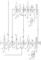
図3は、本実施例における内燃機関の制御の流れを示すフローチャートである。なお、本ルーチンは、CU40により所定時間毎(例えば、10ms毎)に繰り返し実行される。
ステップS1では、セーリングストップ中フラグが「1」となっているか否かを判定する。ステップS1において、セーリングストップ中フラグが「1」であればステップS6へ進む。ステップS1において、セーリングストップ中フラグが「0」であればステップS2へ進む。
ステップS2では、コーストストップ中フラグが「1」となっているか否かを判定する。ステップS2において、コーストストップ中フラグが「1」であればステップS13へ進む。ステップS2において、コーストストップ中フラグが「0」であればステップS3へ進む。
ステップS3では、走行中の車両の車速が中高速であるか否かを判定する。換言すると、トルクコンバータ2のロックアップ機構におけるロックアップクラッチが締結される車速であるか否かを判定する。具体的には、車速が例えば15km/h以上であるか否かを判定する。トルクコンバータ2のロックアップ機構のロックアップクラッチは、車両が中高速走行状態であれば締結され、低速走行状態であれば開放される。
ステップS3において、車速が中高速であると判定された場合、すなわち車速が例えば15km/h以上であると判定された場合には、ステップS4へ進む。ステップS3において、車速が中高速でないと判定された場合、すなわち車速が例えば15km/h未満であると判定された場合には、ステップS11へ進む。
ステップS4では、セーリングストップを実施するための条件、すなわちセーリングストップ条件が成立しているか否かを判定する。セーリングストップ条件は、内燃機関自動停止条件である。
セーリングストップ条件は、例えば、車両の走行中にアクセルペダルが踏み込まれた状態(アクセルON状態)から踏み込まれていない状態(アクセルペダルから足が離れた状態、つまりアクセルOFF状態)となり、バッテリのSOCが所定値以上あるような場合に成立する。つまり、セーリングストップ条件は、駆動力要求が無い場合に成立する。
ステップS4にてセーリングストップ条件が成立していると判定されると、内燃機関1への燃料供給を停止するとともに、フォワードクラッチ5を開放し、ステップS5に進む。ステップS4にてセーリングストップ条件が成立していないと判定されると、今回のルーチンを終了する。
ステップS5では、セーリングストップ中フラグを「1」とする。
ステップS6では、内燃機関1の再始動要求の有無を判定する。例えば、アクセルペダルの踏み込みがある(アクセルON)場合や、バッテリのSOCが所定値以下になる等の車両の電力確保が必要なときに、再始動要求有と判定される。ステップS6にて再始動要求有と判定されると、ステップS7へ進む。ステップS6にて再始動要求が無い判定されると、今回のルーチンを終了する。
ステップS7では、現在の内燃機関1の機関回転数が予め設定されたセーリングストップ用第1回転数以上であるか否かを判定する。セーリングストップ用第1回転数は、第1回転数に相当するものであって、後述するコーストストップ用第1回転数よりも小さい値である。セーリングストップ用第1回転数は、例えば350rpm程度の値である。
ステップS7にて機関回転数がセーリングストップ用第1回転数以上であると判定されると、ステップS8へ進む。ステップS7にて機関回転数がセーリングストップ用第1回転数未満であると判定されると、ステップS9へ進む。
ステップS8では、燃焼リカバリ始動により内燃機関1を再始動してステップS10へ進む。
ステップS9では、クランキングリカバリ始動により内燃機関1を再始動してステップS10へ進む。
ステップS10では、セーリングストップ中フラグを「0」とする。
ステップS11では、コーストストップを実施するための条件、すなわちコーストストップ条件が成立しているか否かを判定する。コーストストップ条件は、内燃機関自動停止条件である。
コーストストップ条件は、例えば、ブレーキペダルが踏み込まれた状態(ブレーキスイッチ23がON状態)の減速中に、バッテリのSOCが所定値以上あるような場合に成立する。
ステップS11にてコーストストップ条件が成立していると判定されると、内燃機関1への燃料供給を停止するとともに、フォワードクラッチ5を締結し、ステップS12に進む。ステップS11にてコーストストップ条件が成立していないと判定されると、今回のルーチンを終了する。
ステップS12では、コーストストップ中フラグを「1」とする。
ステップS13では、内燃機関1の再始動要求の有無を判定する。例えば、アクセルペダルが踏み込まれたり(アクセルON)、ブレーキペダルが踏み込まれなくなったり(ブレーキスイッチ23がOFF)、バッテリのSOCが所定値以下になる等の車両の電力確保が必要なときに、再始動要求有と判定される。ステップS13にて再始動要求有と判定されると、ステップS14へ進む。ステップS13にて再始動要求が無い判定されると、今回のルーチンを終了する。
ステップS14では、現在の内燃機関1の機関回転数が予め設定されたコーストストップ用第1回転数以上であるか否かを判定する。コーストストップ用第1回転数は、第1回転数に相当するものであって、セーリングストップ用第1回転数よりも大きい値である。コーストストップ用第1回転数は、例えば500rpm程度の値である。
ステップS14にて機関回転数がコーストストップ用第1回転数以上であると判定されると、ステップS15へ進む。ステップS14にて機関回転数がコーストストップ用第1回転数未満であると判定されると、ステップS16へ進む。
ステップS15では、燃焼リカバリ始動により内燃機関1を再始動してステップS17へ進む。
ステップS16では、クランキングリカバリ始動により内燃機関1を再始動してステップS17へ進む。
ステップS17では、コーストストップ中フラグを「0」とする。
なお、上述した実施例では、変速機が無段変速機であったが、本願発明は有段の自動変速機を有する車両にも適用可能である。
また、上述した実施例は、内燃機関の制御方法及び内燃機関の制御装置に関するものである。
Claims (4)
- 車両の走行中に燃料供給を自動停止した該車両の駆動源となる内燃機関に対して燃料供給を再開するにあたって、上記内燃機関の機関回転数が所定の第1回転数未満であれば、上記内燃機関に燃料供給を再開する際に上記内燃機関をクランキングし、
上記第1回転数は、上記内燃機関と変速機との間に配置されたトルクコンバータのロックアップクラッチが締結状態のとき、該ロックアップクラッチが開放状態のときよりも低くなるよう設定される内燃機関の制御方法。 - アクセルペダルが踏み込まれておらず、上記ロックアップクラッチと上記車両の駆動輪との間に配置されたクラッチが開放され、上記ロックアップクラッチが締結された状態から上記内燃機関への燃料供給を再開する第1再始動時の上記第1回転数は、ブレーキペダルが踏み込まれ、上記クラッチが締結され、上記ロックアップクラッチが開放された状態から上記内燃機関への燃料供給を再開する第2再始動時の上記第1回転数よりも小さくなるよう設定される請求項1に記載の内燃機関の制御方法。
- 上記第1再始動時においては、上記クラッチが開放されている請求項2に記載の内燃機関の制御方法。
- 車両の駆動源となる内燃機関と、
上記内燃機関と変速機との間に配置されたトルクコンバータと、
所定の条件が成立すると車両の走行中に燃料供給を自動停止した上記内燃機関に対して燃料供給を再開するにあたって、上記内燃機関の機関回転数が所定の第1回転数未満であれば、上記内燃機関に燃料供給を再開する際に上記内燃機関をクランキングする制御部と、を有し、
上記第1回転数は、上記トルクコンバータのロックアップクラッチが締結状態のとき、該ロックアップクラッチが開放状態のときよりも低くなるよう設定される内燃機関の制御装置。
Priority Applications (5)
| Application Number | Priority Date | Filing Date | Title |
|---|---|---|---|
| JP2019547209A JP6741167B2 (ja) | 2017-10-02 | 2017-10-02 | 内燃機関の制御方法及び内燃機関の制御装置 |
| PCT/JP2017/035776 WO2019069345A1 (ja) | 2017-10-02 | 2017-10-02 | 内燃機関の制御方法及び内燃機関の制御装置 |
| CN201780095579.6A CN111183078B (zh) | 2017-10-02 | 2017-10-02 | 内燃机的控制方法及内燃机的控制装置 |
| US16/652,602 US11174803B2 (en) | 2017-10-02 | 2017-10-02 | Internal combustion engine control method and internal combustion engine control device |
| EP17928007.8A EP3693237B1 (en) | 2017-10-02 | 2017-10-02 | Internal combustion engine control method and internal combustion engine control device |
Applications Claiming Priority (1)
| Application Number | Priority Date | Filing Date | Title |
|---|---|---|---|
| PCT/JP2017/035776 WO2019069345A1 (ja) | 2017-10-02 | 2017-10-02 | 内燃機関の制御方法及び内燃機関の制御装置 |
Publications (1)
| Publication Number | Publication Date |
|---|---|
| WO2019069345A1 true WO2019069345A1 (ja) | 2019-04-11 |
Family
ID=65994487
Family Applications (1)
| Application Number | Title | Priority Date | Filing Date |
|---|---|---|---|
| PCT/JP2017/035776 Ceased WO2019069345A1 (ja) | 2017-10-02 | 2017-10-02 | 内燃機関の制御方法及び内燃機関の制御装置 |
Country Status (5)
| Country | Link |
|---|---|
| US (1) | US11174803B2 (ja) |
| EP (1) | EP3693237B1 (ja) |
| JP (1) | JP6741167B2 (ja) |
| CN (1) | CN111183078B (ja) |
| WO (1) | WO2019069345A1 (ja) |
Cited By (4)
| Publication number | Priority date | Publication date | Assignee | Title |
|---|---|---|---|---|
| JP2023070953A (ja) * | 2021-11-10 | 2023-05-22 | トヨタ自動車株式会社 | ハイブリッド車両の制御装置 |
| CN116608070A (zh) * | 2022-02-08 | 2023-08-18 | 丰田自动车株式会社 | 用于混合动力车辆的控制装置 |
| WO2023176249A1 (ja) * | 2022-03-18 | 2023-09-21 | ジヤトコ株式会社 | 車両の制御装置、車両の制御方法及びプログラム |
| EP4219924A4 (en) * | 2020-09-24 | 2023-11-15 | Nissan Motor Co., Ltd. | METHOD FOR CONTROLLING AN INTERNAL COMBUSTION ENGINE AND DEVICE FOR CONTROLLING AN INTERNAL COMBUSTION ENGINE |
Families Citing this family (2)
| Publication number | Priority date | Publication date | Assignee | Title |
|---|---|---|---|---|
| EP4556705A1 (en) * | 2023-11-17 | 2025-05-21 | Volvo Truck Corporation | System and method of controlling a vehicle |
| EP4556704A1 (en) | 2023-11-17 | 2025-05-21 | Volvo Truck Corporation | System and method of controlling a vehicle |
Citations (4)
| Publication number | Priority date | Publication date | Assignee | Title |
|---|---|---|---|---|
| JP2013043572A (ja) * | 2011-08-24 | 2013-03-04 | Toyota Motor Corp | 車両の制御装置 |
| JP2015205526A (ja) * | 2014-04-17 | 2015-11-19 | トヨタ自動車株式会社 | ハイブリッド車両 |
| JP2016114037A (ja) | 2014-12-18 | 2016-06-23 | 日立オートモティブシステムズ株式会社 | エンジン制御装置 |
| JP2017137945A (ja) * | 2016-02-04 | 2017-08-10 | ジヤトコ株式会社 | 車両の制御装置、及び車両の制御方法 |
Family Cites Families (11)
| Publication number | Priority date | Publication date | Assignee | Title |
|---|---|---|---|---|
| JP3488654B2 (ja) * | 1999-03-09 | 2004-01-19 | 本田技研工業株式会社 | ハイブリッド車両のエンジン制御装置 |
| JP4329268B2 (ja) * | 2001-01-26 | 2009-09-09 | 株式会社デンソー | エンジン制御装置 |
| US9764726B2 (en) * | 2009-01-02 | 2017-09-19 | Ford Global Technologies, Llc | Methods and systems for assisted direct start control |
| JP5149846B2 (ja) * | 2009-03-19 | 2013-02-20 | 株式会社デンソー | 内燃機関の自動停止始動制御装置 |
| JP5575522B2 (ja) | 2010-03-31 | 2014-08-20 | 本田技研工業株式会社 | ハイブリッド車両の動力制御装置 |
| JP5548599B2 (ja) * | 2010-12-02 | 2014-07-16 | ジヤトコ株式会社 | コーストストップ車両およびその制御方法 |
| JP5857672B2 (ja) * | 2011-11-24 | 2016-02-10 | 日産自動車株式会社 | 車両のエンジン自動停止制御装置 |
| US9039570B2 (en) * | 2012-05-04 | 2015-05-26 | Ford Global Technologies, Llc | Methods and systems for adjusting driveline disconnect clutch operation |
| JP6071066B2 (ja) * | 2013-09-30 | 2017-02-01 | 日産自動車株式会社 | エンジン自動停止車両の制御装置 |
| US10183663B2 (en) * | 2014-08-18 | 2019-01-22 | Ford Global Technologies, Llc | Methods and systems for starting an engine |
| WO2017130779A1 (ja) * | 2016-01-25 | 2017-08-03 | 日産自動車株式会社 | 車両のセーリングストップ制御方法及び制御装置 |
-
2017
- 2017-10-02 CN CN201780095579.6A patent/CN111183078B/zh active Active
- 2017-10-02 EP EP17928007.8A patent/EP3693237B1/en active Active
- 2017-10-02 WO PCT/JP2017/035776 patent/WO2019069345A1/ja not_active Ceased
- 2017-10-02 JP JP2019547209A patent/JP6741167B2/ja active Active
- 2017-10-02 US US16/652,602 patent/US11174803B2/en active Active
Patent Citations (4)
| Publication number | Priority date | Publication date | Assignee | Title |
|---|---|---|---|---|
| JP2013043572A (ja) * | 2011-08-24 | 2013-03-04 | Toyota Motor Corp | 車両の制御装置 |
| JP2015205526A (ja) * | 2014-04-17 | 2015-11-19 | トヨタ自動車株式会社 | ハイブリッド車両 |
| JP2016114037A (ja) | 2014-12-18 | 2016-06-23 | 日立オートモティブシステムズ株式会社 | エンジン制御装置 |
| JP2017137945A (ja) * | 2016-02-04 | 2017-08-10 | ジヤトコ株式会社 | 車両の制御装置、及び車両の制御方法 |
Non-Patent Citations (1)
| Title |
|---|
| See also references of EP3693237A4 |
Cited By (9)
| Publication number | Priority date | Publication date | Assignee | Title |
|---|---|---|---|---|
| EP4219924A4 (en) * | 2020-09-24 | 2023-11-15 | Nissan Motor Co., Ltd. | METHOD FOR CONTROLLING AN INTERNAL COMBUSTION ENGINE AND DEVICE FOR CONTROLLING AN INTERNAL COMBUSTION ENGINE |
| US11859588B2 (en) | 2020-09-24 | 2024-01-02 | Nissan Motor Co., Ltd. | Method for controlling internal combustion engine, and device for controlling internal combustion engine |
| JP2023070953A (ja) * | 2021-11-10 | 2023-05-22 | トヨタ自動車株式会社 | ハイブリッド車両の制御装置 |
| JP7729185B2 (ja) | 2021-11-10 | 2025-08-26 | トヨタ自動車株式会社 | ハイブリッド車両の制御装置 |
| CN116608070A (zh) * | 2022-02-08 | 2023-08-18 | 丰田自动车株式会社 | 用于混合动力车辆的控制装置 |
| WO2023176249A1 (ja) * | 2022-03-18 | 2023-09-21 | ジヤトコ株式会社 | 車両の制御装置、車両の制御方法及びプログラム |
| JPWO2023176249A1 (ja) * | 2022-03-18 | 2023-09-21 | ||
| JP7795612B2 (ja) | 2022-03-18 | 2026-01-07 | ジヤトコ株式会社 | 車両の制御装置、車両の制御方法及びプログラム |
| US12528469B2 (en) | 2022-03-18 | 2026-01-20 | Jatco Ltd | Control device for vehicle, control method for vehicle, and program |
Also Published As
| Publication number | Publication date |
|---|---|
| CN111183078B (zh) | 2022-10-11 |
| US20200240341A1 (en) | 2020-07-30 |
| CN111183078A (zh) | 2020-05-19 |
| JP6741167B2 (ja) | 2020-08-19 |
| US11174803B2 (en) | 2021-11-16 |
| JPWO2019069345A1 (ja) | 2020-06-18 |
| EP3693237A4 (en) | 2020-10-28 |
| EP3693237B1 (en) | 2021-06-23 |
| EP3693237A1 (en) | 2020-08-12 |
Similar Documents
| Publication | Publication Date | Title |
|---|---|---|
| JP6741167B2 (ja) | 内燃機関の制御方法及び内燃機関の制御装置 | |
| US9470156B2 (en) | Vehicle engine automatic control device and vehicle engine automatic control method | |
| EP2789834B1 (en) | Automatic vehicle-engine control device | |
| EP3715609B1 (en) | Internal combustion engine control method and internal combustion engine control device | |
| JP5011835B2 (ja) | 車両用制御装置 | |
| JP7628549B2 (ja) | 内燃機関の制御方法及び内燃機関の制御装置 | |
| JP6422543B2 (ja) | 制御装置 | |
| JP3858972B2 (ja) | 車両の駆動装置 | |
| JP2014163437A (ja) | 制御装置 | |
| JP6868710B2 (ja) | 内燃機関の制御方法及び内燃機関の制御装置 | |
| WO2019069344A1 (ja) | 車両の制御方法及び車両の制御装置 | |
| WO2019069444A1 (ja) | 内燃機関の制御方法及び内燃機関の制御装置 | |
| JP6053393B2 (ja) | アイドルストップ車両の制御装置 | |
| JP6481536B2 (ja) | エンジン制御方法及びエンジン制御装置 | |
| JP2022052806A (ja) | 内燃機関の制御方法及び内燃機関の制御装置 | |
| JP2022044378A (ja) | 車両 | |
| JP2013136963A (ja) | 制御装置 | |
| JP2018127103A (ja) | 車両及び車両の制御方法 |
Legal Events
| Date | Code | Title | Description |
|---|---|---|---|
| 121 | Ep: the epo has been informed by wipo that ep was designated in this application |
Ref document number: 17928007 Country of ref document: EP Kind code of ref document: A1 |
|
| ENP | Entry into the national phase |
Ref document number: 2019547209 Country of ref document: JP Kind code of ref document: A |
|
| NENP | Non-entry into the national phase |
Ref country code: DE |
|
| ENP | Entry into the national phase |
Ref document number: 2017928007 Country of ref document: EP Effective date: 20200504 |