WO2019069358A1 - 認識プログラム、認識方法および認識装置 - Google Patents
認識プログラム、認識方法および認識装置 Download PDFInfo
- Publication number
- WO2019069358A1 WO2019069358A1 PCT/JP2017/035915 JP2017035915W WO2019069358A1 WO 2019069358 A1 WO2019069358 A1 WO 2019069358A1 JP 2017035915 W JP2017035915 W JP 2017035915W WO 2019069358 A1 WO2019069358 A1 WO 2019069358A1
- Authority
- WO
- WIPO (PCT)
- Prior art keywords
- subject
- sensors
- recognition
- skeleton
- individual sensors
- Prior art date
- Legal status (The legal status is an assumption and is not a legal conclusion. Google has not performed a legal analysis and makes no representation as to the accuracy of the status listed.)
- Ceased
Links
Images









Classifications
-
- G—PHYSICS
- G06—COMPUTING OR CALCULATING; COUNTING
- G06V—IMAGE OR VIDEO RECOGNITION OR UNDERSTANDING
- G06V40/00—Recognition of biometric, human-related or animal-related patterns in image or video data
- G06V40/20—Movements or behaviour, e.g. gesture recognition
-
- G—PHYSICS
- G06—COMPUTING OR CALCULATING; COUNTING
- G06T—IMAGE DATA PROCESSING OR GENERATION, IN GENERAL
- G06T7/00—Image analysis
- G06T7/70—Determining position or orientation of objects or cameras
- G06T7/73—Determining position or orientation of objects or cameras using feature-based methods
-
- A—HUMAN NECESSITIES
- A61—MEDICAL OR VETERINARY SCIENCE; HYGIENE
- A61B—DIAGNOSIS; SURGERY; IDENTIFICATION
- A61B5/00—Measuring for diagnostic purposes; Identification of persons
- A61B5/0059—Measuring for diagnostic purposes; Identification of persons using light, e.g. diagnosis by transillumination, diascopy, fluorescence
- A61B5/0077—Devices for viewing the surface of the body, e.g. camera, magnifying lens
-
- A—HUMAN NECESSITIES
- A61—MEDICAL OR VETERINARY SCIENCE; HYGIENE
- A61B—DIAGNOSIS; SURGERY; IDENTIFICATION
- A61B5/00—Measuring for diagnostic purposes; Identification of persons
- A61B5/103—Measuring devices for testing the shape, pattern, colour, size or movement of the body or parts thereof, for diagnostic purposes
- A61B5/11—Measuring movement of the entire body or parts thereof, e.g. head or hand tremor or mobility of a limb
- A61B5/1113—Local tracking of patients, e.g. in a hospital or private home
- A61B5/1114—Tracking parts of the body
-
- A—HUMAN NECESSITIES
- A61—MEDICAL OR VETERINARY SCIENCE; HYGIENE
- A61B—DIAGNOSIS; SURGERY; IDENTIFICATION
- A61B5/00—Measuring for diagnostic purposes; Identification of persons
- A61B5/103—Measuring devices for testing the shape, pattern, colour, size or movement of the body or parts thereof, for diagnostic purposes
- A61B5/11—Measuring movement of the entire body or parts thereof, e.g. head or hand tremor or mobility of a limb
- A61B5/1116—Determining posture transitions
-
- A—HUMAN NECESSITIES
- A61—MEDICAL OR VETERINARY SCIENCE; HYGIENE
- A61B—DIAGNOSIS; SURGERY; IDENTIFICATION
- A61B5/00—Measuring for diagnostic purposes; Identification of persons
- A61B5/103—Measuring devices for testing the shape, pattern, colour, size or movement of the body or parts thereof, for diagnostic purposes
- A61B5/11—Measuring movement of the entire body or parts thereof, e.g. head or hand tremor or mobility of a limb
- A61B5/1121—Determining geometric values, e.g. centre of rotation or angular range of movement
- A61B5/1122—Determining geometric values, e.g. centre of rotation or angular range of movement of movement trajectories
-
- A—HUMAN NECESSITIES
- A61—MEDICAL OR VETERINARY SCIENCE; HYGIENE
- A61B—DIAGNOSIS; SURGERY; IDENTIFICATION
- A61B5/00—Measuring for diagnostic purposes; Identification of persons
- A61B5/103—Measuring devices for testing the shape, pattern, colour, size or movement of the body or parts thereof, for diagnostic purposes
- A61B5/11—Measuring movement of the entire body or parts thereof, e.g. head or hand tremor or mobility of a limb
- A61B5/1123—Discriminating type of movement, e.g. walking or running
-
- A—HUMAN NECESSITIES
- A61—MEDICAL OR VETERINARY SCIENCE; HYGIENE
- A61B—DIAGNOSIS; SURGERY; IDENTIFICATION
- A61B5/00—Measuring for diagnostic purposes; Identification of persons
- A61B5/103—Measuring devices for testing the shape, pattern, colour, size or movement of the body or parts thereof, for diagnostic purposes
- A61B5/11—Measuring movement of the entire body or parts thereof, e.g. head or hand tremor or mobility of a limb
- A61B5/1126—Measuring movement of the entire body or parts thereof, e.g. head or hand tremor or mobility of a limb using a particular sensing technique
- A61B5/1128—Measuring movement of the entire body or parts thereof, e.g. head or hand tremor or mobility of a limb using a particular sensing technique using image analysis
-
- A—HUMAN NECESSITIES
- A61—MEDICAL OR VETERINARY SCIENCE; HYGIENE
- A61B—DIAGNOSIS; SURGERY; IDENTIFICATION
- A61B5/00—Measuring for diagnostic purposes; Identification of persons
- A61B5/68—Arrangements of detecting, measuring or recording means, e.g. sensors, in relation to patient
- A61B5/6887—Arrangements of detecting, measuring or recording means, e.g. sensors, in relation to patient mounted on external non-worn devices, e.g. non-medical devices
- A61B5/6889—Rooms
-
- A—HUMAN NECESSITIES
- A61—MEDICAL OR VETERINARY SCIENCE; HYGIENE
- A61B—DIAGNOSIS; SURGERY; IDENTIFICATION
- A61B5/00—Measuring for diagnostic purposes; Identification of persons
- A61B5/72—Signal processing specially adapted for physiological signals or for diagnostic purposes
- A61B5/7235—Details of waveform analysis
- A61B5/7264—Classification of physiological signals or data, e.g. using neural networks, statistical classifiers, expert systems or fuzzy systems
- A61B5/7267—Classification of physiological signals or data, e.g. using neural networks, statistical classifiers, expert systems or fuzzy systems involving training the classification device
-
- A—HUMAN NECESSITIES
- A63—SPORTS; GAMES; AMUSEMENTS
- A63B—APPARATUS FOR PHYSICAL TRAINING, GYMNASTICS, SWIMMING, CLIMBING, OR FENCING; BALL GAMES; TRAINING EQUIPMENT
- A63B24/00—Electric or electronic controls for exercising apparatus of preceding groups; Controlling or monitoring of exercises, sportive games, training or athletic performances
- A63B24/0062—Monitoring athletic performances, e.g. for determining the work of a user on an exercise apparatus, the completed jogging or cycling distance
-
- G—PHYSICS
- G06—COMPUTING OR CALCULATING; COUNTING
- G06T—IMAGE DATA PROCESSING OR GENERATION, IN GENERAL
- G06T7/00—Image analysis
- G06T7/50—Depth or shape recovery
- G06T7/55—Depth or shape recovery from multiple images
-
- G—PHYSICS
- G06—COMPUTING OR CALCULATING; COUNTING
- G06T—IMAGE DATA PROCESSING OR GENERATION, IN GENERAL
- G06T7/00—Image analysis
- G06T7/70—Determining position or orientation of objects or cameras
-
- G—PHYSICS
- G06—COMPUTING OR CALCULATING; COUNTING
- G06V—IMAGE OR VIDEO RECOGNITION OR UNDERSTANDING
- G06V20/00—Scenes; Scene-specific elements
- G06V20/60—Type of objects
- G06V20/64—Three-dimensional [3D] objects
-
- G—PHYSICS
- G06—COMPUTING OR CALCULATING; COUNTING
- G06V—IMAGE OR VIDEO RECOGNITION OR UNDERSTANDING
- G06V40/00—Recognition of biometric, human-related or animal-related patterns in image or video data
- G06V40/20—Movements or behaviour, e.g. gesture recognition
- G06V40/23—Recognition of whole body movements, e.g. for sport training
-
- A—HUMAN NECESSITIES
- A63—SPORTS; GAMES; AMUSEMENTS
- A63B—APPARATUS FOR PHYSICAL TRAINING, GYMNASTICS, SWIMMING, CLIMBING, OR FENCING; BALL GAMES; TRAINING EQUIPMENT
- A63B24/00—Electric or electronic controls for exercising apparatus of preceding groups; Controlling or monitoring of exercises, sportive games, training or athletic performances
- A63B24/0062—Monitoring athletic performances, e.g. for determining the work of a user on an exercise apparatus, the completed jogging or cycling distance
- A63B2024/0071—Distinction between different activities, movements, or kind of sports performed
-
- A—HUMAN NECESSITIES
- A63—SPORTS; GAMES; AMUSEMENTS
- A63B—APPARATUS FOR PHYSICAL TRAINING, GYMNASTICS, SWIMMING, CLIMBING, OR FENCING; BALL GAMES; TRAINING EQUIPMENT
- A63B71/00—Games or sports accessories not covered in groups A63B1/00 - A63B69/00
- A63B71/06—Indicating or scoring devices for games or players, or for other sports activities
- A63B71/0619—Displays, user interfaces and indicating devices, specially adapted for sport equipment, e.g. display mounted on treadmills
- A63B2071/0647—Visualisation of executed movements
-
- A—HUMAN NECESSITIES
- A63—SPORTS; GAMES; AMUSEMENTS
- A63B—APPARATUS FOR PHYSICAL TRAINING, GYMNASTICS, SWIMMING, CLIMBING, OR FENCING; BALL GAMES; TRAINING EQUIPMENT
- A63B2220/00—Measuring of physical parameters relating to sporting activity
- A63B2220/05—Image processing for measuring physical parameters
-
- A—HUMAN NECESSITIES
- A63—SPORTS; GAMES; AMUSEMENTS
- A63B—APPARATUS FOR PHYSICAL TRAINING, GYMNASTICS, SWIMMING, CLIMBING, OR FENCING; BALL GAMES; TRAINING EQUIPMENT
- A63B2220/00—Measuring of physical parameters relating to sporting activity
- A63B2220/20—Distances or displacements
-
- A—HUMAN NECESSITIES
- A63—SPORTS; GAMES; AMUSEMENTS
- A63B—APPARATUS FOR PHYSICAL TRAINING, GYMNASTICS, SWIMMING, CLIMBING, OR FENCING; BALL GAMES; TRAINING EQUIPMENT
- A63B2220/00—Measuring of physical parameters relating to sporting activity
- A63B2220/80—Special sensors, transducers or devices therefor
- A63B2220/803—Motion sensors
-
- A—HUMAN NECESSITIES
- A63—SPORTS; GAMES; AMUSEMENTS
- A63B—APPARATUS FOR PHYSICAL TRAINING, GYMNASTICS, SWIMMING, CLIMBING, OR FENCING; BALL GAMES; TRAINING EQUIPMENT
- A63B71/00—Games or sports accessories not covered in groups A63B1/00 - A63B69/00
- A63B71/06—Indicating or scoring devices for games or players, or for other sports activities
- A63B71/0619—Displays, user interfaces and indicating devices, specially adapted for sport equipment, e.g. display mounted on treadmills
- A63B71/0622—Visual, audio or audio-visual systems for entertaining, instructing or motivating the user
-
- G—PHYSICS
- G06—COMPUTING OR CALCULATING; COUNTING
- G06T—IMAGE DATA PROCESSING OR GENERATION, IN GENERAL
- G06T2207/00—Indexing scheme for image analysis or image enhancement
- G06T2207/10—Image acquisition modality
- G06T2207/10028—Range image; Depth image; 3D point clouds
-
- G—PHYSICS
- G06—COMPUTING OR CALCULATING; COUNTING
- G06T—IMAGE DATA PROCESSING OR GENERATION, IN GENERAL
- G06T2207/00—Indexing scheme for image analysis or image enhancement
- G06T2207/30—Subject of image; Context of image processing
- G06T2207/30196—Human being; Person
-
- G—PHYSICS
- G06—COMPUTING OR CALCULATING; COUNTING
- G06T—IMAGE DATA PROCESSING OR GENERATION, IN GENERAL
- G06T2207/00—Indexing scheme for image analysis or image enhancement
- G06T2207/30—Subject of image; Context of image processing
- G06T2207/30221—Sports video; Sports image
Definitions
- the present invention relates to a recognition program, a recognition method and a recognition apparatus.
- a distance image hereinafter, also referred to as a depth image
- a distance sensor hereinafter, also referred to as a depth sensor
- the device performs label division on a part of a person based on, for example, a distance image output from one distance sensor.
- the device extracts a skeletal model having a three-dimensional skeletal position based on the labeled sites. After that, the device recognizes the posture and movement of the person based on the extracted skeletal model.
- an occlusion may occur in which a part of the person is hidden by a part of the object or the person's own person.
- the accuracy of skeletal recognition in the three dimensions of the person decreases, making it difficult to recognize complex movements. That is, the occurrence of occlusion lowers the recognition accuracy of the skeleton or the like of the person.
- An aspect of the present invention is to provide a recognition program, a recognition method, and a recognition device capable of suppressing a decrease in recognition accuracy due to the occurrence of an occlusion.
- the recognition program causes the computer to execute a process of acquiring the positional relationship between a plurality of sensors that sense the distance to the subject.
- the recognition program temporarily classifies the orientation of the subject with respect to each of the individual sensors into any one of a plurality of classifications, based on each of sensing data acquired by the individual sensors included in the plurality of sensors.
- the recognition program is a process of calculating the likelihood for each combination with respect to the combination corresponding to the positional relationship between the plurality of sensors, based on the result of the temporary classification of the direction of the subject with respect to each of the individual sensors.
- On a computer The recognition program causes the computer to execute a process of classifying the orientation of the subject corresponding to each of the individual sensors in accordance with the calculated likelihood for each combination.
- FIG. 1 is a diagram showing an example of the configuration of a recognition system according to the embodiment.
- FIG. 2 is a view showing an example of the arrangement of a plurality of distance sensors.
- FIG. 3 is a view showing an example of the arrangement of a plurality of distance sensors.
- FIG. 4 is a diagram showing an example of an occlusion by an object.
- FIG. 5 is a diagram showing an example of an occlusion by an object.
- FIG. 6 is a diagram showing an example of self occlusion.
- FIG. 7 is a diagram showing an example of self occlusion.
- FIG. 8 is a block diagram showing an example of the configuration of the recognition device of the embodiment.
- FIG. 9 is a diagram illustrating an example of the combination storage unit.
- FIG. 10 is a diagram showing an example of a posture recognition range and a posture recognition unit.
- FIG. 11 is a diagram illustrating an example of integration of point cloud data of a plurality of distance sensors.
- FIG. 12 is a diagram showing an example of integrating the coordinates of each distance sensor into world coordinates.
- FIG. 13 is a diagram showing an example of integrating the coordinates of each distance sensor into the coordinates of the main sensor.
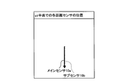
- FIG. 14 is a diagram showing an example of the position of each distance sensor in the xz plane.
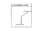
- FIG. 15 is a diagram showing an example of the position of each distance sensor in the yz plane.
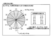
- FIG. 16 is a diagram showing an example of all combinations of posture numbers in the direction of rotation.
- FIG. 11 is a diagram illustrating an example of integration of point cloud data of a plurality of distance sensors.
- FIG. 12 is a diagram showing an example of integrating the coordinates of each distance sensor into world coordinates.
- FIG. 13 is a diagram showing an example of
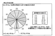
- FIG. 17 is a diagram showing an example of all combinations of posture numbers in the upside-down direction.
- FIG. 18 is a diagram showing an example of determination of the dictionary number in the rotation direction.
- FIG. 19 is a diagram showing an example of determination of dictionary numbers in the upside-down direction.
- FIG. 20 is a view showing an example of a posture recognition result in the upside-down direction and a selection range of the skeleton recognition dictionary.
- FIG. 21 is a view showing an example of a posture recognition result in the rotation direction and a selection range of the skeleton recognition dictionary.
- FIG. 22 is a diagram showing an example of boundary pixels in a part label image.
- FIG. 23 is a diagram showing an example of boundary point groups of joint sites.
- FIG. 24 is a diagram showing an example of joint coordinates.
- FIG. 25 is a diagram showing an example of a part label image.
- FIG. 26 is a flowchart showing an example of the first recognition process of the embodiment.
- FIG. 27 is a flowchart showing an example of the sensor positional relationship calculation process.
- FIG. 28 is a flowchart illustrating an example of the combination determination process.
- FIG. 29 is a flowchart showing an example of the posture recognition process.
- FIG. 30 is a flowchart illustrating an example of the dictionary determination process.
- FIG. 31 is a flowchart showing an example of the second recognition process of the embodiment.
- FIG. 32 is a diagram illustrating an example of a computer that executes a recognition program.
- FIG. 1 is a diagram showing an example of the configuration of a recognition system according to the embodiment.
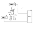
- the recognition system 1 shown in FIG. 1 includes distance sensors 10 a and 10 b and a recognition device 100.
- the distance sensors 10a and 10b are not distinguished from one another, they are simply expressed as the distance sensor 10.
- the number of distance sensors 10 is not limited, and an arbitrary number of distance sensors 10 may be provided as long as the number is plural.
- the distance sensors 10a and 10b and the recognition device 100 are communicably connected to each other by wire or wirelessly.
- the recognition system 1 is an example of a system that measures the person 5 who is a subject with the distance sensor 10 and recognizes the posture or the like of the person 5 based on the measurement result.
- the distance sensor 10 measures (senses) the distance of the object for each pixel using, for example, an infrared laser or the like, and outputs a distance image of, for example, 320 ⁇ 240 pixels.
- the distance image includes the distance and angle to each pixel. That is, the distance image is a depth image representing the depth of the subject viewed from the distance sensor (depth sensor) 10.
- the distance sensor 10 measures the distance of an object (object) at a distance of, for example, approximately 15 m.
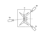
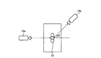
- FIGS. 2 and 3 are diagrams showing an example of the arrangement of a plurality of distance sensors. Both are examples of gymnastics, but they can be arranged according to other sports and other people's movements.
- FIG. 2 shows an example of the arrangement of the distance sensor 10 in the case of a suspension game.
- positioning in the case of using three distance sensors 10 is shown.
- the main sensor 10 a is disposed at a position in the direction in which the majority of players on the suspension wheel 21 face the front.
- the sub sensor 10 b is disposed at a position in the diagonal rear direction of the swing wheel 21.
- the sub sensor 10c is disposed at a position in the diagonally backward direction of the swing wheel 21 and at a position opposite to the sub sensor 10b.
- FIG. 3 is a view showing an example of the arrangement of a plurality of distance sensors.
- the arrangement in the case of using two distance sensors 10 is shown.
- the main sensor 10 a is disposed at a position on the horse 22 in the front direction of the player.
- the sub sensor 10 b is disposed at an angle of about 45 ° from the axis of the main sensor 10 a in the diagonally backward direction of the horses 22.
- 4 and 5 are diagrams showing an example of occlusion by an object.
- an occlusion occurs in which a part of the foot of the person who performs the horse competition hides behind the horse of the device which is the object.
- an occlusion occurs in which a part of the foot of the person who plays the horse competition hides behind the horse of the appliance which is the object.
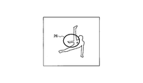
- FIG. 6 and 7 show an example of self occlusion.
- an occlusion occurs in which a part of the arm of the person who is playing the horse competition hides behind the foot.
- FIG. 7 as shown in the area 27, the arm of the person who is engaged in the suspension competition is overlapped with the body, and occlusion occurs.
- the recognition device 100 recognizes the posture or the like of the person 5 based on the distance images input from the plurality of distance sensors 10.
- the recognition device 100 acquires the positional relationship between a plurality of distance sensors 10 that sense the distance to the person 5 who is the subject.
- the recognition device 100 determines, based on each of sensing data acquired by individual distance sensors 10 included in the plurality of distance sensors 10, the orientation (posture) of the person 5 as the subject with respect to each of the individual distance sensors 10 Temporarily classify into any of the classifications.
- the recognition apparatus 100 calculates the likelihood for each combination for the combination corresponding to the positional relationship between the plurality of distance sensors 10 based on the result of temporary classification of the direction of the subject with respect to each individual distance sensor 10 Do.
- the recognition device 100 classifies the orientation (posture) of the person 5 as the subject corresponding to each of the individual distance sensors 10 according to the calculated likelihood of each combination. Thereby, the recognition apparatus 100 can suppress the decrease in the classification accuracy of the direction (posture) of the person 5 due to the occurrence of the occlusion, that is, the recognition accuracy.
- the recognition device 100 acquires the positional relationship between the plurality of distance sensors 10 that sense the distance to the person 5 who is the subject.
- the recognition device 100 acquires sensing data acquired by individual distance sensors 10 included in a plurality of distance sensors 10.
- the recognition device 100 selects one of the skeletons of the subject viewed from the individual distance sensors 10 based on each of the acquired sensing data and the skeleton recognition dictionary selected in accordance with the orientation of the subject with respect to each of the individual distance sensors 10. Estimate the dimensional position respectively.
- the recognition apparatus 100 determines the three-dimensional position of the skeleton of the subject based on the estimation result of the three-dimensional position of the skeleton of the subject viewed from each of the individual distance sensors 10 and the positional relationship between the plurality of distance sensors 10. Do.
- the recognition device 100 can suppress the decrease in the recognition accuracy due to the occurrence of the occlusion.
- FIG. 8 is a block diagram showing an example of the configuration of the recognition device of the embodiment.
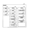
- the recognition device 100 includes a communication unit 110, a display unit 111, an operation unit 112, a storage unit 120, and a control unit 130.
- the recognition apparatus 100 may have various functional units of a known computer, for example, various functional units such as various input devices and voice output devices, in addition to the functional units shown in FIG.
- a portable personal computer or the like can be adopted. Not only the portable personal computer described above but also a stationary personal computer may be employed as the recognition device 100.
- the communication unit 110 is realized by, for example, a network interface card (NIC).
- NIC network interface card
- the communication unit 110 is a communication interface that is connected to the distance sensor 10 by wire or wireless and manages communication of information with the distance sensor 10.
- the display unit 111 is a display device for displaying various information.
- the display unit 111 is realized by, for example, a liquid crystal display or the like as a display device.
- the display unit 111 displays various screens such as a display screen input from the control unit 130.
- the operation unit 112 is an input device that receives various operations from the user of the recognition device 100.
- the operation unit 112 is realized by, for example, a keyboard, a mouse or the like as an input device.
- the operation unit 112 outputs the operation input by the user to the control unit 130 as operation information.
- the operation unit 112 may be realized by a touch panel or the like as an input device, and the display device of the display unit 111 and the input device of the operation unit 112 may be integrated.
- the storage unit 120 is realized by, for example, a storage device such as a random access memory (RAM), a semiconductor memory device such as a flash memory, or a hard disk or an optical disk.
- the storage unit 120 includes a positional relationship storage unit 121, a combination storage unit 122, a posture recognition dictionary storage unit 123, and a skeleton recognition dictionary storage unit 124. Further, the storage unit 120 stores information used for processing in the control unit 130.
- the positional relationship storage unit 121 stores information on the positional relationship of the distance sensor 10.
- the positional relationship storage unit 121 integrates the data of each distance sensor 10 into position coordinates of the main sensor 10 that acquires the main information (for example, a distance image from the front of the performer) or world coordinates.
- the position coordinates are stored in association with each distance sensor 10.
- the positional relationship storage unit 121 stores the rotation direction angle and the inversion direction angle indicating the angle when the vector corresponding to each distance sensor 10 is projected on the xz plane and the yz plane (distance direction from sensor to object Is the z axis, the height direction perpendicular to the z axis is the y axis, and the horizontal direction is the x axis).
- the rotation direction is a direction of rotation about an axis from the head of the person 5 who is the subject toward the foot, that is, a direction in which the person 5 twists the body in an upright state.
- the upside-down direction is a direction in which the upright person 5 falls forward, that is, a direction in which the person 5 turns (turns around).
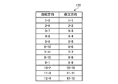
- the combination storage unit 122 stores all combinations of posture numbers calculated based on the angles between the distance sensors 10.
- FIG. 9 is a diagram illustrating an example of the combination storage unit. As shown in FIG. 9, the combination storage unit 122 has items performed in the “rotation direction” and the “inverted direction”.
- the “rotation direction” is information indicating a combination of posture numbers between the distance sensors 10 in the rotation direction.
- the “inverted direction” is information indicating a combination of posture numbers between the distance sensors 10 in the inverted direction.
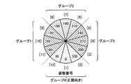
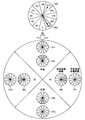
- FIG. 10 is a diagram showing an example of a posture recognition range and a posture recognition unit.
- the posture recognition unit the direction of the person 5, that is, the posture is recognized in units of 30 °.
- recognizing the direction of the person 5 is referred to as posture recognition.
- the direction of the person 5 is represented by a posture number by dividing the circle every 30 ° and swinging the posture number from “1” to “12” counterclockwise from the front direction of the person 5.
- the posture numbers are grouped into four directions as the direction of the person 5.
- the group “0” is in the front direction, to which posture numbers “12”, “1”, and “2” belong.
- the group “1” is the right hand direction of the person 5 and belongs to posture numbers “9”, “10”, and “11”.
- the group “2” is the back direction of the person 5 and includes posture numbers "6", "7", and "8".
- the group “3” is the left hand direction of the person 5 and belongs to posture numbers "3", "4" and "5".
- the posture recognition range corresponds to the group “0" to “3"
- the group “0” is the posture recognition range in the front direction
- the group “1” is the posture recognition range in the right direction
- the group “2” Is the backward posture recognition range
- the group “3” is the left hand posture recognition range.
- the skeleton recognition dictionary storage unit 124 used in skeleton recognition performs learning by expanding the range by one posture number to the left and right of the posture recognition range in machine learning.
- the skeleton recognition learning range in the posture recognition range of the group “0” is a range of posture numbers “11”, “12”, “1”, “2”, and “3”. This is provided so that skeletal recognition can be normally performed even if a slight error occurs in posture recognition.
- the posture recognition dictionary storage unit 123 stores dictionary information used when determining which posture the distance image corresponds to.
- the posture recognition dictionary storage unit 123 stores, for example, a posture number for uniquely identifying a posture and a feature of a distance image corresponding to the posture number.
- the posture recognition dictionary storage unit 123 is generated by performing machine learning on various distance images. In this case, as an algorithm of machine learning, for example, random forest or deep learning can be used.
- the skeleton recognition dictionary storage unit 124 is dictionary information indicating an assumed joint position (skeleton position) for each posture number (dictionary number).
- the skeleton recognition dictionary storage unit 124 associates, for example, a posture number, a distance image corresponding to the posture number, and information on a joint position of a person (skeleton dictionary information). Although illustration is omitted, it is assumed that skeleton dictionary information corresponding to each posture number exists. That is, the skeleton recognition dictionary storage unit 124 is an example of a multiclass classifier used to obtain a part label image from a distance image.
- the skeleton recognition dictionary storage unit 124 is generated by performing machine learning on various distance images corresponding to posture numbers and information on joint positions of a person. In this case, as an algorithm of machine learning, for example, random forest or deep learning can be used.
- the control unit 130 is realized, for example, by a program stored in an internal storage device being executed by using a RAM as a work area by a central processing unit (CPU), a graphics processing unit (GPU) or the like. Further, the control unit 130 may be realized by an integrated circuit such as an application specific integrated circuit (ASIC) or a field programmable gate array (FPGA).
- ASIC application specific integrated circuit
- FPGA field programmable gate array
- the control unit 130 includes an acquisition unit 131, a calculation unit 132, a first determination unit 133, a posture recognition unit 134, an estimation unit 135, and a second determination unit 136, and performs the information processing described below. Implement or perform a function or action. That is, each processing unit of the control unit 130 executes the first recognition process and the second recognition process. Note that the internal configuration of the control unit 130 is not limited to the configuration shown in FIG. 8, and may be another configuration as long as it performs the information processing described later.
- the acquisition unit 131 receives and acquires distance images (sensing data) from the distance sensors 10 via the communication unit 110.
- the acquisition unit 131 outputs the acquired distance image to the calculation unit 132, the posture recognition unit 134, and the estimation unit 135.
- the calculation unit 132 converts the distance image for each distance sensor 10 into point cloud data.
- the point cloud data is data obtained by converting each pixel of the distance image into a point represented by three axes of x, y and z at coordinates based on the individual distance sensor 10.
- the calculation unit 132 integrates point cloud data converted by each distance sensor 10 into one coordinate.
- FIG. 11 is a diagram illustrating an example of integration of point cloud data of a plurality of distance sensors.
- the calculation unit 132 generates point cloud data based on the distance images 31 a and 31 b output from the main sensor 10 a and the sub sensor 10 b that measure the person 5.
- the calculation unit 132 integrates the generated point cloud data into, for example, the coordinates of the main sensor 10a, and generates integrated point cloud data 32.
- the calculation unit 132 aligns each point cloud data with the integrated coordinates.
- the calculation unit 132 determines sensor parameters and affine transformation matrices for transforming coordinates of each distance sensor 10 by calibration. The calibration is performed using a device selected for calibration or a general-purpose calibration jig.
- the alignment sensor parameters are ⁇ xrot representing the x-axis center rotation angle, ⁇ yrot representing the y-axis center rotation angle, ⁇ zrot representing the z-axis center rotation angle, t x representing the x-axis parallel movement, and t representing the y-axis parallel movement y z, t z representing the z-axis translation.
- the affine transformation matrix becomes Equations (1) to (4) shown below.
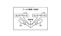
- FIG. 12 is a diagram showing an example of integrating the coordinates of each distance sensor into world coordinates.
- the calculation unit 132 integrates the coordinates of the main sensor 10a and the coordinates of the sub sensor 10b into world coordinates using the sensor parameters 11a and 11b.
- FIG. 13 is a diagram showing an example of integrating the coordinates of each distance sensor into the coordinates of the main sensor.
- the calculation unit 132 integrates the coordinates of the main sensor 10a and the coordinates of the sub sensor 10b into the coordinates of the main sensor 10a using the sensor parameters 12a and 12b. In this case, all sensor parameters 12a corresponding to the main sensor 10a are zero.
- the calculation unit 132 generates a reverse affine transformation matrix for returning to the original position of each distance sensor 10 from each sensor parameter corresponding to the integrated point cloud data obtained by calibration.
- the calculation unit 132 For each distance sensor 10, the calculation unit 132 multiplies the unit vector, for example, the z-direction unit vector by the reverse affine transformation matrix to calculate a vector after conversion.
- the calculation unit 132 projects each vector after conversion corresponding to each distance sensor 10 on the xz plane, and acquires a rotation direction angle. That is, the calculation unit 132 determines the installation position on the plane of each distance sensor 10.
- the calculation unit 132 projects each vector after conversion corresponding to each distance sensor 10 on the yz plane, and acquires an inverted direction angle. That is, the calculation unit 132 determines the relative height and elevation angle of each distance sensor 10.
- the relative heights and elevation angles of the distance sensors 10 are set to be the same, and the vectors corresponding to the distance sensors 10 are substantially the same.
- the calculation unit 132 stores the acquired rotation direction angle and the inversion direction angle in the positional relationship storage unit 121. After storing the rotation direction angle and the inversion direction angle in the positional relationship storage unit 121, the calculation unit 132 outputs a combination determination instruction to the first determination unit 133.
- FIG. 14 is a diagram showing an example of the position of each distance sensor in the xz plane.
- each vector corresponding to the main sensor 10a and the sub sensor 10b has a direction reflecting the sensor arrangement.
- FIG. 15 is a diagram showing an example of the position of each distance sensor in the yz plane. As described above, in the example of FIG. 15, the vectors corresponding to the main sensor 10a and the sub sensor 10b have substantially the same direction.
- the first determination unit 133 refers to the positional relationship storage unit 121 and determines the rotation direction angle and the inversion direction angle of each distance sensor 10. get.
- the first determination unit 133 determines an angle between the distance sensors 10, that is, an angle between vectors corresponding to the distance sensors 10, based on the acquired rotation direction angle and the inversion direction angle of the distance sensors 10.
- the first determination unit 133 determines all combinations of posture numbers based on the angles between the distance sensors 10 for each of the rotation direction and the inversion direction.
- the first determination unit 133 stores the determined combination in the combination storage unit 122.
- FIG. 16 is a diagram showing an example of all combinations of posture numbers in the direction of rotation.
- the combination of is determined.
- These 12 combinations are possible combinations of the positional relationship between the main sensor 10a and the sub sensor 10b.
- FIG. 17 is a diagram showing an example of all combinations of posture numbers in the upside-down direction.
- 12 combinations of “1-1”, “2-2”, “3-3”,... As all combinations of posture numbers corresponding to angles between the main sensor 10a and the sub sensor 10b.
- the combination of is determined.
- These 12 combinations are possible combinations of the positional relationship between the main sensor 10a and the sub sensor 10b.
- the 1st determination part 133 determines a combination similarly about the case where three or more distance sensors 10 are provided.
- the calculation unit 132 and the first determination unit 133 are an example of an acquisition unit that acquires the positional relationship between the plurality of distance sensors 10 that sense (measure) the distance to the person 5 who is the subject.
- the acquisition part in this case is good also as an acquisition part including the acquisition part 131 which acquires a distance image from each distance sensor 10.
- the posture recognition unit 134 receives the distance image corresponding to each distance sensor 10 from the acquisition unit 131.
- the posture recognition unit 134 refers to the posture recognition dictionary storage unit 123 and executes posture recognition for each distance sensor 10 based on the distance image of each distance sensor 10.
- the posture recognition unit 134 calculates the probability of the orientation (posture) of the subject, which is the result of posture recognition, for each combination of posture numbers in the direction of rotation and the direction of inversion. Since the posture recognition unit 134 has 12 posture numbers in each of the distance sensors 10 in the direction of rotation and the direction of inversion, the posture recognition unit 134 uses, for example, the top 15 pairs with high probability among 144.
- the probability for each combination of posture numbers in the direction of rotation and the direction of inversion is not limited to the top 15 sets, and any number of sets may be used.
- the posture recognition unit 134 refers to the combination storage unit 122 for each of the rotation direction and the inversion direction, adds the probability of the direction of the subject for each combination of posture numbers between the distance sensors 10, and The likelihood of each combination of posture numbers is calculated.
- the posture recognition unit 134 has, for example, the probability of the posture number “2” of the main sensor 10 a corresponding to the combination “2-6” is “0.3”, and the probability of the posture number “6” of the sub sensor 10 b is “0.4”. If it is “,” the likelihood of the combination “2-6” is calculated to be “0.7”.
- the posture recognition unit 134 calculates the likelihoods of all combinations, and determines the posture number of the combination that maximizes the likelihood of each combination of posture numbers among the distance sensors 10.
- the posture recognition unit 134 determines the determined posture number as the dictionary number for each distance sensor 10.
- the dictionary number corresponds to the posture number of the skeleton recognition dictionary storage unit 124, and is a number specifying the skeleton recognition dictionary used in estimating the three-dimensional position of the skeleton of the subject by the dictionary number.
- Posture recognition unit 134 outputs the determined rotation direction and inversion direction dictionary number of each distance sensor 10 to estimation unit 135.
- FIG. 18 is a diagram showing an example of determination of the dictionary number in the rotation direction. As shown in FIG. 18, for example, when the likelihood "0.7" of the combination "2-6" is maximum in the direction of rotation, the posture number "2" is determined as the dictionary number of the main sensor 10a. The posture number "6" is determined as the dictionary number of the sub sensor 10b.
- FIG. 19 is a diagram showing an example of determination of dictionary numbers in the upside-down direction. As shown in FIG. 19, for example, when the likelihood "0.8" of the combination "10-10" is maximum in the upside-down direction, the posture number "10" is a dictionary of the main sensor 10a and the sub sensor 10b. Determine the number.
- FIG. FIG. 20 is a view showing an example of a posture recognition result in the upside-down direction and a selection range of the skeleton recognition dictionary.
- the result of posture recognition in the upside-down direction is classified into four directions: erect, prone, inverted, and supine.
- the selection range of the skeleton recognition dictionary is expanded by one posture number in the direction that is wider than the posture recognition result. That is, the skeleton recognition dictionary range 34a corresponds to the erect posture recognition result 33a, and the skeleton recognition dictionary range 34b corresponds to the prone posture recognition result 33b.
- the framework recognition dictionary range 34c corresponds to the inverted posture recognition result 33c
- the skeleton recognition dictionary range 34d corresponds to the supine posture recognition result 33d. That each framework recognition dictionary range is wider than the posture recognition result is to prepare for an error of posture recognition.
- the vectors corresponding to the main sensor 10a and the sub sensor 10b are both directed to the 0 ° direction, that is, to the attitude number “1”. At this time, the posture recognition result is "right up”, and the skeleton recognition dictionary range is also "right up”.
- FIG. 21 is a view showing an example of a posture recognition result in the rotation direction and a selection range of the skeleton recognition dictionary.
- the posture recognition results in the rotation direction are classified into four directions of front, right, back, and left.
- the selection range of the skeleton recognition dictionary is expanded by one posture number in the direction that is wider than the posture recognition result. That is, the skeleton recognition dictionary range 37a corresponds to the front posture recognition result 36a, and the skeleton recognition dictionary range 37b corresponds to the right posture recognition result 36b.
- a skeleton recognition dictionary range 37c corresponds to the back posture recognition result 36c, and a skeleton recognition dictionary range 37d corresponds to the left posture recognition result 36d. That each framework recognition dictionary range is wider than the posture recognition result is to prepare for an error of posture recognition.
- the vector 39a corresponding to the main sensor 10a is directed to the direction of 330 °, that is, posture number "2".
- the posture recognition result is “front”
- the skeleton recognition dictionary range is also “front”.
- the vector 39 b corresponding to the sub sensor 10 b is directed in the 210 ° direction, that is, the posture number “6”.
- the posture recognition result is "back”
- the skeleton recognition dictionary range is also "back”.
- the posture recognition unit 134 determines the orientation of the subject with respect to each of the individual distance sensors 10 in a plurality of classifications. Tentatively classify each into one of them.
- the plurality of classifications correspond to posture numbers.
- the posture recognition unit 134 compares the combinations corresponding to the positional relationship between the plurality of distance sensors 10 with each other on the basis of the result (posture number) of the temporary classification of the direction of the subject with respect to each individual distance sensor 10. Calculate the likelihood.
- the posture recognition unit 134 classifies the direction of the subject corresponding to each of the individual distance sensors 10 according to the calculated likelihood of each combination.
- the orientation of the subject to be classified is the dictionary number corresponding to the posture number. That is, the posture recognition unit 134 is a first classification unit that temporarily classifies the direction of the subject, a calculation unit that calculates the likelihood for each combination, and the object corresponding to each distance sensor 10 according to the likelihood for each combination. It is an example of the 2nd classification part which classifies direction.
- the posture recognition unit 134 calculates the likelihood for each combination with respect to the combination corresponding to the positional relationship between the plurality of distance sensors 10 in the direction in which the subject is inverted and in the direction in which the subject rotates. Further, the posture recognition unit 134 classifies the direction of the subject corresponding to each of the individual distance sensors 10 according to the likelihood obtained by adding the likelihood of each of the individual distance sensors 10 corresponding to the combination.
- the distance image is input from the acquisition unit 131 to the estimation unit 135, and the dictionary numbers of the rotation direction and the inversion direction of each distance sensor 10 are input from the posture recognition unit 134.
- the estimation unit 135 refers to the skeleton recognition dictionary storage unit 124, and generates a region label image using the skeleton recognition dictionary based on the distance image of each distance sensor 10 and the dictionary number.
- the region label image is an image obtained by labeling the region of the person 5 who is the subject according to the distance (depth).
- the estimation unit 135 extracts boundary pixels of each joint site from the generated site label image.
- the estimation unit 135 converts a pixel corresponding to a boundary pixel of the distance image of each distance sensor 10 into a point group based on the extracted boundary pixels of each joint region, and extracts a boundary point group of each joint region.
- the estimation unit 135 outputs the boundary point group of each joint site extracted for each distance sensor 10 to the second determination unit 136.
- the estimation unit 135 acquires sensing data acquired by the individual distance sensors 10 included in the plurality of distance sensors 10.
- the estimation unit 135 selects one of the skeletons of the subject viewed from the individual distance sensor 10 based on each of the acquired sensing data and the skeleton recognition dictionary selected according to the orientation of the subject with respect to each individual distance sensor 10. Estimate the dimensional position respectively.
- the estimation unit 135 generates a part label image representing the part of the subject by the part label using the skeleton recognition dictionary based on the sensing data, and based on the part label in the generated part label image, Estimate the 3D position.
- the estimation unit 135 estimates the three-dimensional position of the skeleton of the subject using data in the vicinity of the boundary of the part label among the sensing data.
- the estimation unit 135 calculates the variance for the boundary point group of each joint part of each distance sensor 10, and uses the reciprocal of the calculated variance to randomly thin out or increase the boundary point group. It may be output to the second determination unit 136. That is, the estimation unit 135 calculates, for each of the individual distance sensors 10, the variance of data in the vicinity of the boundary. The estimation unit 135 performs sensing data in which sensing data of each individual distance sensor 10 is randomly thinned out using the reciprocal of the calculated variance, or sensing data in which sensing data of each individual distance sensor 10 is randomly increased. To estimate the three-dimensional position of the subject's skeleton.
- FIG. 22 is a diagram showing an example of boundary pixels in a part label image.
- pixels at the boundary of the region label are extracted as boundary pixels of the joint region.
- Boundary pixels 42a and 42b correspond to the right wrist and the right elbow, respectively.
- the boundary pixels 42c and 42d correspond to the left wrist and the left elbow, respectively.
- FIG. 23 is a diagram showing an example of boundary point groups of joint sites.
- the point cloud data 43 in FIG. 23 is obtained by converting the distance image corresponding to the part label image 41 into three coordinate axes of x, y and z.
- the point group corresponding to the boundary pixel of the joint region extracted in FIG. 22 is extracted as the boundary point group of the joint region.
- Boundary point groups 44a and 44b correspond to the boundary pixels 42a and 42b, and correspond to the right wrist and the right elbow, respectively.
- the boundary point groups 44c and 44d correspond to the boundary pixels 42c and 42d, and correspond to the left wrist and the left elbow, respectively.
- the second determination unit 136 receives the boundary point group of each joint portion extracted from the estimation unit 135 for each distance sensor 10.
- the second determination unit 136 refers to the positional relationship storage unit 121, and integrates the boundary point group of each joint portion extracted for each distance sensor 10 into the coordinates of the main sensor 10a using the sensor parameter.
- the second determination unit 136 may use world coordinates as coordinates to be integrated.
- the second determination unit 136 obtains the center of gravity for the integrated boundary point group of each joint site, and determines the coordinates of the center of gravity as joint coordinates. That is, the second determination unit 136 determines the three-dimensional position of the skeleton of the person 5 who is the subject.
- the second determination unit 136 outputs the determined joint coordinates to, for example, a processing unit or processing device that performs fitting with the distance image. That is, the second determination unit 136 outputs the determined joint coordinates to, for example, a processing unit or processing unit that performs gymnastic scoring, or outputs it as a skeletal model so as to be usable for CG (Computer Graphics) animation. be able to.
- CG Computer Graphics
- the second determination unit 136 may process the determined joint coordinates into, for example, a specific format and output the processed coordinates to an external storage device or the like (not shown).
- the second determination unit 136 may generate a three-dimensional model based on the determined joint coordinates, and output the three-dimensional model to the display unit 111 for display.
- the second determination unit 136 Determine 3D position. Further, the second determination unit 136 determines the center of gravity of the boundary of the region label as the joint position.
- the second determination unit 136 may obtain the center of gravity for the boundary point group of each joint site of the distance sensor 10 in which the distance to the person 5 who is the subject is closest. That is, the second determination unit 136 calculates the center of gravity of the boundary using the estimation result of the three-dimensional position of the skeleton viewed from the distance sensor 10, which is the closest to the subject among the plurality of distance sensors 10. May be In addition, the second determination unit 136 may determine, for example, the positions (coordinates) of parts such as the centers of the shoulders and the crotch, based on the determined plurality of joint positions (joint coordinates). In addition, the second determination unit 136 may determine the center of gravity of the site label as the position (coordinates) of the site corresponding to the site label in the head, the toe, and the like.
- FIG. 24 is a diagram showing an example of joint coordinates.
- labeling is performed for the person 5a, and each joint position represented by each joint coordinate 45, each site represented by each gravity center 46 of the site label, and each site based on a plurality of joint coordinates 45 The position 47 is shown determined.
- FIG. 25 is a diagram showing an example of a part label image.
- the part label image of the person 5b shown in FIG. 25 is a part label image corresponding to the label division for the person 5a in FIG.
- the person 5a and the person 5b are assumed to be the same person although the position of the right hand is different.
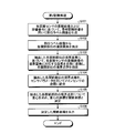
- FIG. 26 is a flowchart showing an example of the first recognition process of the embodiment.
- the acquisition unit 131 of the recognition device 100 receives and acquires distance images from the distance sensors 10.
- the acquisition unit 131 outputs the acquired distance image to the calculation unit 132, the posture recognition unit 134, and the estimation unit 135.
- the calculation unit 132 executes a sensor positional relationship calculation process (step S1).
- FIG. 27 is a flowchart showing an example of the sensor positional relationship calculation process.
- the calculation unit 132 converts the distance image for each distance sensor 10 into point cloud data.
- the calculation unit 132 integrates point cloud data converted by each distance sensor 10 into the coordinates of the main sensor 10a (step S11).
- the calculation unit 132 performs calibration of each point cloud data with the integrated coordinates.
- the calculation unit 132 determines the sensor parameters and the affine transformation matrix of each distance sensor 10 by calibration (step S12).
- the calculation unit 132 generates a reverse affine transformation matrix of each distance sensor 10 from each sensor parameter (step S13).
- the calculation unit 132 calculates, for each distance sensor 10, a vector after conversion by applying a reverse affine transformation matrix to a unit vector (step S14).
- the calculation unit 132 projects each vector after conversion corresponding to each distance sensor 10 on the xz plane, and acquires a rotation direction angle (step S15). In addition, the calculation unit 132 projects each vector after conversion corresponding to each distance sensor 10 on the yz plane, and acquires an inverted direction angle (step S16). The calculation unit 132 stores the acquired rotation direction angle and the inversion direction angle in the positional relationship storage unit 121 (step S17), outputs a combination determination instruction to the first determination unit 133, and returns to the original processing. Thus, the calculation unit 132 can calculate the positional relationship of each distance sensor 10.
- step S2 when the combination determination instruction is input from the calculation unit 132, the first determination unit 133 executes a combination determination process (step S2).
- FIG. 28 is a flowchart illustrating an example of the combination determination process.
- the first determination unit 133 refers to the positional relationship storage unit 121 and acquires the rotation direction angle and the inversion direction angle of each distance sensor 10.
- the first determination unit 133 determines an angle between the distance sensors 10 based on the acquired rotation direction angle and the inversion direction angle of each distance sensor 10 (Step S21).
- the first determination unit 133 determines all combinations of posture numbers based on the angles between the distance sensors 10 for each of the rotation direction and the inversion direction (step S22).
- the first determination unit 133 stores the determined combination in the combination storage unit 122 (step S23), and returns to the original process.
- the first determination unit 133 can determine the combination of posture numbers based on the angles between the distance sensors 10.
- the posture recognition unit 134 executes posture recognition processing (step S3).
- FIG. 29 is a flowchart showing an example of the posture recognition process.
- the posture recognition unit 134 performs posture recognition for each of the distance sensors 10 based on the distance image of each of the distance sensors 10 with reference to the posture recognition dictionary storage unit 123 (step S31).
- the posture recognition unit 134 calculates the probability of the orientation of the subject, which is the result of posture recognition, for each combination of posture numbers in the direction of rotation and the direction of inversion (step S32), and returns to the original processing.
- the posture recognition unit 134 can recognize the direction (posture) of the subject.
- the posture recognition unit 134 executes the dictionary determination processing when the posture recognition processing is completed (step S4).
- FIG. 30 is a flowchart illustrating an example of the dictionary determination process.
- the posture recognition unit 134 refers to the combination storage unit 122 for the rotation direction and the inversion direction, adds the probability of the direction of the subject for each combination of the posture numbers between the distance sensors 10, and calculates the posture numbers between the distance sensors 10 The likelihood of each combination is calculated (step S41).
- the posture recognition unit 134 determines a posture number of a combination that maximizes the likelihood of each combination of posture numbers among the distance sensors 10 (step S42). The posture recognition unit 134 determines the determined posture number as the dictionary number for each distance sensor 10 (step S43), and returns to the original processing. Thus, the posture recognition unit 134 can determine the dictionary number of the skeleton recognition dictionary used in skeleton recognition.
- the posture recognition unit 134 outputs the determined dictionary number of each distance sensor 10 to the estimation unit 135 (step S5).
- the recognition device 100 can output the dictionary number of the skeleton recognition dictionary used for each of the distance sensors 10 as a result of the posture recognition of the person 5. That is, the recognition device 100 can suppress the decrease in the classification accuracy of the direction of the person 5 due to the occurrence of occlusion, that is, the recognition accuracy.
- the recognition device 100 can integrate point cloud data based on distance images of a plurality of distance sensors 10 at high speed, and can perform posture recognition with high accuracy. Further, the recognition device 100 can improve the accuracy of posture recognition as compared with the case where one distance sensor 10 is provided. When the position of each distance sensor 10 does not change, the positional relationship calculation process and the combination determination process may be omitted when the first recognition process is repeatedly performed.
- FIG. 31 is a flowchart showing an example of the second recognition process of the embodiment.
- the distance image is input from the acquisition unit 131 to the estimation unit 135 of the recognition device 100, and the dictionary number of each distance sensor 10 is input from the posture recognition unit 134.
- the estimation unit 135 refers to the skeleton recognition dictionary storage unit 124, and generates a part label image using the skeleton recognition dictionary based on the distance image and the dictionary number of each distance sensor 10 (step S101).
- the estimation unit 135 extracts boundary pixels of each joint site from the generated site label image (step S102).
- the estimation unit 135 converts pixels corresponding to the boundary pixels of the distance image of each distance sensor 10 into a point group based on the extracted boundary pixels of each joint region, and extracts the boundary point group of each joint region (Step S103).
- the estimation unit 135 outputs the boundary point group of each joint site extracted for each distance sensor 10 to the second determination unit 136.
- the second determination unit 136 refers to the positional relationship storage unit 121, and uses the sensor parameter to set the boundary point group of each joint portion extracted for each distance sensor 10 input from the estimation unit 135 to the coordinates of the main sensor 10a. Integration is performed (step S104).
- the second determination unit 136 obtains the center of gravity for the integrated boundary point group of each joint site, and determines the coordinates of the center of gravity as joint coordinates (step S105).
- the second determination unit 136 outputs the determined joint coordinates to, for example, another processing unit or processing apparatus (step S106).
- the recognition device 100 can suppress the decrease in the recognition accuracy due to the occurrence of the occlusion.
- the increase of the point group by the plurality of distance sensors 10 (n units) can improve the accuracy in the fitting located at the latter stage of the skeletal recognition by at most 1 / sqrt (n).
- the recognition device 100 can output high-speed and high-accuracy skeleton recognition results.
- the recognition device 100 acquires the positional relationship between the plurality of distance sensors 10 that sense the distance to the subject. In addition, the recognition device 100 determines, based on each of the sensing data acquired by the individual distance sensors 10 included in the plurality of distance sensors 10, the orientation of the subject with respect to each of the individual distance sensors 10 in any of the plurality of classifications. Into each, temporary classification. In addition, the recognition device 100 sets the likelihood for each combination with respect to the combination corresponding to the positional relationship between the plurality of distance sensors 10 based on the result of temporary classification of the direction of the subject with respect to each individual distance sensor 10. calculate. In addition, the recognition device 100 classifies the orientation of the subject corresponding to each individual sensor according to the calculated likelihood for each combination. As a result, the recognition device 100 can suppress a decrease in recognition accuracy due to the occurrence of an occlusion.
- the recognition apparatus 100 calculates the likelihood for each combination with respect to the combination corresponding to the positional relationship between the plurality of distance sensors 10 in the direction in which the subject is inverted and the direction in which the subject rotates. As a result, the recognition device 100 can suppress a decrease in recognition accuracy due to the occurrence of an occlusion.
- the recognition device 100 classifies the direction of the subject corresponding to each of the individual distance sensors 10 according to the likelihood obtained by adding the likelihood of each of the individual distance sensors 10 corresponding to the combination. As a result, the classification accuracy of the direction of the subject in the distance sensor 10 can be improved.
- the recognition device 100 acquires the positional relationship between the plurality of distance sensors 10 that sense the distance to the subject. Further, the recognition device 100 acquires sensing data acquired by individual distance sensors 10 included in the plurality of distance sensors 10. In addition, the recognition device 100 can recognize the skeleton of the subject viewed from the individual distance sensor 10 based on each of the acquired sensing data and the skeleton recognition dictionary selected according to the orientation of the subject with respect to the individual distance sensor 10. The three-dimensional position of each is estimated. In addition, the recognition device 100 determines the three-dimensional position of the skeleton of the subject based on the estimation result of the three-dimensional position of the skeleton of the subject viewed from each of the individual distance sensors 10 and the positional relationship between the plurality of distance sensors 10. Decide. As a result, the recognition device 100 can suppress a decrease in recognition accuracy due to the occurrence of an occlusion.
- the recognition apparatus 100 also generates a part label image representing the part of the subject by the part label using the skeleton recognition dictionary based on the sensing data.
- the recognition device 100 also estimates the three-dimensional position of the skeleton of the subject based on the part label in the generated part label image. As a result, it is possible to estimate the three-dimensional position of the skeleton of the subject for each distance sensor 10.
- the recognition apparatus 100 estimates the three-dimensional position of the skeleton of the subject using data in the vicinity of the boundary of the part label among the sensing data. As a result, the recognition device 100 can reduce the amount of processing of conversion from the distance image to the point cloud data.
- the recognition device 100 determines the center of gravity of the boundary of the part label as the joint position. As a result, the recognition device 100 can determine the position of the joint.
- the recognition device 100 calculates the center of gravity of the boundary using the estimation result of the three-dimensional position of the skeleton viewed from the distance sensor 10 among the plurality of distance sensors 10 which is closest to the subject. As a result, the recognition device 100 can improve the calculation accuracy of the center of gravity of the boundary.
- the recognition device 100 also calculates the variance of data in the vicinity of the boundary for each of the individual distance sensors 10. Further, the recognition device 100 randomly increases sensing data in which sensing data of each individual distance sensor 10 is randomly thinned out or sensing data of each individual distance sensor 10 using a reciprocal of the calculated variance. The sensing data is used to estimate the three-dimensional position of the skeleton of the subject. As a result, the recognition device 100 can improve the calculation speed of the center of gravity of the boundary or the calculation accuracy.
- the recognition device 100 also determines the position of the site based on the determined plurality of joint positions. As a result, the recognition device 100 can determine the position other than the center of gravity of the boundary of the region label such as the center of both shoulders as the position of the region.
- the recognition device 100 also determines the center of gravity of the site label as the position of the site corresponding to the site label. As a result, the recognition device 100 can determine the position other than the center of gravity of the boundary of the region label such as the head as the position of the region.
- the second recognition process for performing the skeletal recognition is executed using the result of the first recognition process for performing the attitude recognition
- the present invention is not limited to this.
- the second recognition processing of the present embodiment may be performed to perform skeleton recognition.
- skeleton recognition may be performed using another method.
- posture recognition and skeleton recognition are performed by measuring the person 5 who performs gymnastics, but the present invention is not limited to this.
- the present invention may be applied to other scoring competitions such as figure skating, verification of operation in rehabilitation, and analysis of forms such as baseball and golf.
- the lateral rotation direction may be further added to form three axes, or polar coordinates may be used to represent the orientation of the spine of the person 5 and the three angles of rotation of both shoulder lines.
- each component of each unit shown in the drawings does not necessarily have to be physically configured as shown in the drawings. That is, the specific form of the dispersion and integration of each part is not limited to the illustrated one, and all or a part thereof is functionally or physically dispersed or integrated in any unit according to various loads, usage conditions, etc. Can be configured.
- the calculation unit 132, the first determination unit 133, and the posture recognition unit 134 may be integrated.
- the illustrated processes are not limited to the above-described order, and may be performed simultaneously within the range in which the process contents do not contradict each other, or may be performed by changing the order.
- each device may be performed on the CPU (or GPU) in whole or any part thereof. Furthermore, it goes without saying that all or any part of the various processing functions may be executed on a program analyzed and executed by the CPU (or GPU) or on hardware by wired logic.
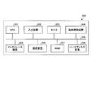
- FIG. 32 is a diagram illustrating an example of a computer that executes a recognition program.
- the computer 200 has a CPU 201 that executes various arithmetic processing, an input device 202 that receives data input, and a monitor 203. Further, the computer 200 is connected by wire or wirelessly to a medium reading device 204 which reads a program or the like from a storage medium, an interface device 205 for connecting to various devices, a distance sensor 10 and other information processing devices. And a communication device 206. The computer 200 also has a RAM 207 for temporarily storing various information, and a hard disk drive 208. Each of the devices 201 to 208 is connected to the bus 209.
- hard disk drive 208 recognition having the same function as each processing unit of acquisition unit 131, calculation unit 132, first determination unit 133, posture recognition unit 134, estimation unit 135, and second determination unit 136 shown in FIG.
- the program is stored. Further, the hard disk drive 208 stores a positional relationship storage unit 121, a combination storage unit 122, a posture recognition dictionary storage unit 123, a skeleton recognition dictionary storage unit 124, and various data for realizing a recognition program.
- the input device 202 receives an input of various information such as operation information from the user of the computer 200, for example.
- the monitor 203 displays various screens such as a display screen to the user of the computer 200, for example.
- the interface device 205 is connected to, for example, a printing device.
- the communication device 206 has, for example, the same function as the communication unit 110 shown in FIG. 8 and is connected to the distance sensor 10 and other information processing devices, and exchanges various information with the distance sensor 10 and other information processing devices. .
- the CPU 201 reads out each program stored in the hard disk device 208, develops the program in the RAM 207, and executes the program to perform various processes.
- these programs can cause the computer 200 to function as the acquisition unit 131, the calculation unit 132, the first determination unit 133, the posture recognition unit 134, the estimation unit 135, and the second determination unit 136 illustrated in FIG.
- the above recognition program does not necessarily have to be stored in the hard disk drive 208.
- the computer 200 may read out and execute a program stored in a storage medium readable by the computer 200.
- the storage medium readable by the computer 200 is, for example, a portable recording medium such as a CD-ROM, a DVD (Digital Versatile Disc), a USB (Universal Serial Bus) memory, a semiconductor memory such as a flash memory, or a hard disk drive.
- the recognition program may be stored in a device connected to a public line, the Internet, a LAN or the like, and the computer 200 may read out the recognition program from these and execute it.
- Reference Signs List 1 recognition system 10 distance sensor 100 recognition unit 110 communication unit 111 display unit 112 operation unit 120 storage unit 121 positional relationship storage unit 122 combination storage unit 123 posture recognition dictionary storage unit 124 skeleton recognition dictionary storage unit 130 control unit 131 acquisition unit 132 calculation Part 133 1st determination part 134 Posture recognition part 135 Estimation part 136 2nd determination part
Landscapes
- Health & Medical Sciences (AREA)
- Engineering & Computer Science (AREA)
- Life Sciences & Earth Sciences (AREA)
- Physics & Mathematics (AREA)
- General Health & Medical Sciences (AREA)
- Computer Vision & Pattern Recognition (AREA)
- Veterinary Medicine (AREA)
- Animal Behavior & Ethology (AREA)
- Public Health (AREA)
- Surgery (AREA)
- Molecular Biology (AREA)
- Medical Informatics (AREA)
- Heart & Thoracic Surgery (AREA)
- Biomedical Technology (AREA)
- Pathology (AREA)
- Biophysics (AREA)
- General Physics & Mathematics (AREA)
- Theoretical Computer Science (AREA)
- Physiology (AREA)
- Oral & Maxillofacial Surgery (AREA)
- Dentistry (AREA)
- Multimedia (AREA)
- Psychiatry (AREA)
- Artificial Intelligence (AREA)
- Human Computer Interaction (AREA)
- Social Psychology (AREA)
- Physical Education & Sports Medicine (AREA)
- Evolutionary Computation (AREA)
- Nuclear Medicine, Radiotherapy & Molecular Imaging (AREA)
- Radiology & Medical Imaging (AREA)
- Signal Processing (AREA)
- Fuzzy Systems (AREA)
- Geometry (AREA)
- Mathematical Physics (AREA)
- Image Analysis (AREA)
Abstract
オクルージョンの発生による認識精度の低下を抑止できる認識プログラム等を提供する。認識プログラムは、被写体(5)までの距離をセンシングする複数のセンサ(10)同士の位置関係を取得する処理をコンピュータ(100)に実行させる。認識プログラムは、複数のセンサに含まれる個別のセンサで取得したセンシングデータのそれぞれに基づいて、個別のセンサそれぞれに対する被写体の向きを、複数の分類のうちいずれかに、それぞれ仮分類する処理をコンピュータに実行させる。認識プログラムは、個別のセンサそれぞれに対する被写体の向きの仮分類の結果に基づいて、複数のセンサ同士の位置関係に対応する組合せに対して、該組合せごとの尤度を算出する処理をコンピュータに実行させる。認識プログラムは、算出した組合せごとの尤度に応じて、個別のセンサそれぞれに対応する被写体の向きを分類する処理をコンピュータに実行させる。
Description
本発明は、認識プログラム、認識方法および認識装置に関する。
従来、人物までの距離をセンシングする距離センサ(以下、深度センサともいう。)が出力する距離画像(以下、深度画像ともいう。)に基づいて、人物の姿勢や動きを認識する装置がある。当該装置は、例えば、1台の距離センサから出力される距離画像に基づいて、人物の部位についてラベル分けを行う。次に、当該装置は、ラベル分けした各部位に基づいて、3次元の骨格位置を持つ骨格モデルを抽出する。その後、当該装置は、抽出した骨格モデルに基づいて、人物の姿勢や動きを認識する。
しかしながら、1台の距離センサを用いて人物の姿勢や動きを認識する場合、例えば、物体や人物自身の部位によって人物の一部が隠れるオクルージョンが発生することがある。オクルージョンが発生すると、人物の3次元における骨格認識の精度が低下し、複雑な動きを認識することが困難となる。すなわち、オクルージョンが発生することにより、人物の骨格等の認識精度が低下する。
一つの側面では、オクルージョンの発生による認識精度の低下を抑止できる認識プログラム、認識方法および認識装置を提供することにある。
一つの態様では、認識プログラムは、被写体までの距離をセンシングする複数のセンサ同士の位置関係を取得する処理をコンピュータに実行させる。認識プログラムは、前記複数のセンサに含まれる個別のセンサで取得したセンシングデータのそれぞれに基づいて、前記個別のセンサそれぞれに対する前記被写体の向きを、複数の分類のうちいずれかに、それぞれ仮分類する処理をコンピュータに実行させる。認識プログラムは、前記個別のセンサそれぞれに対する前記被写体の向きの前記仮分類の結果に基づいて、前記複数のセンサ同士の位置関係に対応する組合せに対して、該組合せごとの尤度を算出する処理をコンピュータに実行させる。認識プログラムは、算出した前記組合せごとの尤度に応じて、前記個別のセンサそれぞれに対応する前記被写体の向きを分類する処理をコンピュータに実行させる。
オクルージョンの発生による認識精度の低下を抑止できる。
以下、図面に基づいて、本願の開示する認識プログラム、認識方法および認識装置の実施例を詳細に説明する。なお、本実施例により、開示技術が限定されるものではない。また、以下の実施例は、矛盾しない範囲で適宜組みあわせてもよい。
図1は、実施例の認識システムの構成の一例を示す図である。図1に示す認識システム1は、距離センサ10a,10bと、認識装置100とを有する。なお、以下の説明では、距離センサ10a,10bを区別しない場合には、単に距離センサ10と表現する。また、認識システム1では、距離センサ10の数は限定されず、複数であれば任意の数の距離センサ10を有するようにしてもよい。距離センサ10a,10bと認識装置100との間は、有線または無線にて、相互に通信可能に接続される。
認識システム1は、被写体である人物5を距離センサ10で測定し、測定結果に基づいて、認識装置100が人物5の姿勢等を認識するシステムの一例である。
距離センサ10は、例えば、赤外線レーザ等を用いて対象物の距離を画素ごとに測定(センシング)し、例えば横320×縦240画素の距離画像を出力する。距離画像には、各画素までの距離および角度が含まれる。つまり、距離画像は、距離センサ(深度センサ)10から見た被写体の深度を表す深度画像である。距離センサ10は、例えば、概ね15mまでの距離にある対象物(被写体)の距離を測定する。
ここで、図2および図3を用いて、距離センサ10の配置について説明する。図2と図3は、複数の距離センサの配置の一例を示す図である。両者とも体操競技における例であるが、他のスポーツや、その他人の動きに応じた配置が可能となる。図2は、つり輪競技の場合における距離センサ10の配置の一例である。なお、図2の例では、距離センサ10を3台用いる場合の配置を示している。図2に示すように、メインセンサ10aは、つり輪21における選手の多数が正面を向く方向の位置に配置する。サブセンサ10bは、つり輪21の斜め後方向の位置に配置する。サブセンサ10cは、つり輪21の斜め後方向の位置であって、サブセンサ10bと反対側の位置に配置する。
図3は、複数の距離センサの配置の一例を示す図である。なお、図3の例では、距離センサ10を2台用いる場合の配置を示している。図3に示すように、メインセンサ10aは、あん馬22における選手の正面方向の位置に配置する。サブセンサ10bは、あん馬22の斜め後方向のメインセンサ10aの軸線上から45°程度斜めの位置に配置する。
ここで、図4から図7を用いてオクルージョンについて説明する。図4および図5は、物体によるオクルージョンの一例を示す図である。図4では、領域24に示すように、あん馬競技を行う人物の足の一部が、物体である器具のあん馬の後方に隠れるオクルージョンが発生している。同様に、図5では、領域25に示すように、あん馬競技を行う人物の足の一部が、物体である器具のあん馬の後方に隠れるオクルージョンが発生している。
図6および図7は、セルフオクルージョンの一例を示す図である。図6では、領域26に示すように、あん馬競技を行う人物の腕の一部が足の後方に隠れるオクルージョンが発生している。図7では、領域27に示すように、つり輪競技を行う人物の腕が胴体と重なりオクルージョンが発生している。
図1の説明に戻って、認識装置100は、複数の距離センサ10から入力される距離画像に基づいて、人物5の姿勢等を認識する。認識装置100は、被写体である人物5までの距離をセンシングする複数の距離センサ10同士の位置関係を取得する。認識装置100は、複数の距離センサ10に含まれる個別の距離センサ10で取得したセンシングデータのそれぞれに基づいて、個別の距離センサ10それぞれに対する被写体である人物5の向き(姿勢)を、複数の分類のうちいずれかに、それぞれ仮分類する。認識装置100は、個別の距離センサ10それぞれに対する前記被写体の向きの仮分類の結果に基づいて、複数の距離センサ10同士の位置関係に対応する組合せに対して、該組合せごとの尤度を算出する。認識装置100は、算出した組合せごとの尤度に応じて、個別の距離センサ10それぞれに対応する被写体である人物5の向き(姿勢)を分類する。これにより、認識装置100は、オクルージョンの発生による人物5の向き(姿勢)の分類精度、つまり認識精度の低下を抑止できる。
また、認識装置100は、被写体である人物5までの距離をセンシングする複数の距離センサ10同士の位置関係を取得する。認識装置100は、複数の距離センサ10に含まれる個別の距離センサ10で取得したセンシングデータを取得する。認識装置100は、取得したセンシングデータのそれぞれと、個別の距離センサ10それぞれに対する被写体の向きに応じて選択された骨格認識辞書とに基づいて、個別の距離センサ10から見た被写体の骨格の3次元位置を、それぞれ推定する。認識装置100は、個別の距離センサ10それぞれから見た被写体の骨格の3次元位置の推定の結果と、複数の距離センサ10同士の位置関係とに基づいて、被写体の骨格の3次元位置を決定する。これにより、認識装置100は、オクルージョンの発生による認識精度の低下を抑止できる。
次に、図8を用いて認識装置100の機能構成について説明する。図8は、実施例の認識装置の構成の一例を示すブロック図である。図8に示すように、認識装置100は、通信部110と、表示部111と、操作部112と、記憶部120と、制御部130とを有する。なお、認識装置100は、図8に示す機能部以外にも既知のコンピュータが有する各種の機能部、例えば各種の入力デバイスや音声出力デバイス等の機能部を有することとしてもかまわない。認識装置100の一例としては、可搬型のパーソナルコンピュータ等を採用できる。なお、認識装置100には、上記の可搬型のパーソナルコンピュータのみならず、据置型のパーソナルコンピュータを採用することもできる。
通信部110は、例えば、NIC(Network Interface Card)等によって実現される。通信部110は、距離センサ10と有線または無線で接続され、距離センサ10との間で情報の通信を司る通信インタフェースである。
表示部111は、各種情報を表示するための表示デバイスである。表示部111は、例えば、表示デバイスとして液晶ディスプレイ等によって実現される。表示部111は、制御部130から入力された表示画面等の各種画面を表示する。
操作部112は、認識装置100のユーザから各種操作を受け付ける入力デバイスである。操作部112は、例えば、入力デバイスとして、キーボードやマウス等によって実現される。操作部112は、ユーザによって入力された操作を操作情報として制御部130に出力する。なお、操作部112は、入力デバイスとして、タッチパネル等によって実現されるようにしてもよく、表示部111の表示デバイスと、操作部112の入力デバイスとは、一体化されるようにしてもよい。
記憶部120は、例えば、RAM(Random Access Memory)、フラッシュメモリ等の半導体メモリ素子、ハードディスクや光ディスク等の記憶装置によって実現される。記憶部120は、位置関係記憶部121と、組合せ記憶部122と、姿勢認識辞書記憶部123と、骨格認識辞書記憶部124とを有する。また、記憶部120は、制御部130での処理に用いる情報を記憶する。
位置関係記憶部121は、距離センサ10の位置関係に関する情報を記憶する。位置関係記憶部121は、各距離センサ10のデータを、最も主要な情報(例えば、演技者の正面からの距離画像)を取得するメインセンサ10の位置座標、または、ワールド座標に統合する場合の位置座標を、各距離センサ10に対応付けて記憶する。また、位置関係記憶部121は、各距離センサ10に対応するベクトルをxz平面およびyz平面に射影した場合の角度を示す自転方向角度および倒立方向角度を記憶する(センサから対象に向けた距離方向がz軸、z軸に垂直な高さ方向がy軸、水平方向をx軸と定義する)。なお、自転方向とは、被写体である人物5の頭部から足に向かう軸に対して回転する方向、つまり、人物5が直立した状態で身体をひねる方向である。また、倒立方向とは、直立した人物5が前に倒れる方向、つまり、人物5が前転(宙返り)を行う方向である。
組合せ記憶部122は、各距離センサ10間の角度に基づいて算出された姿勢番号の全ての組合せを記憶する。図9は、組合せ記憶部の一例を示す図である。図9に示すように、組合せ記憶部122は、「自転方向」、「倒立方向」と行った項目を有する。「自転方向」は、自転方向における各距離センサ10間の姿勢番号の組合せを示す情報である。「倒立方向」は、倒立方向における各距離センサ10間の姿勢番号の組合せを示す情報である。
ここで、図10を用いて姿勢番号について説明する。図10は、姿勢認識範囲および姿勢認識単位の一例を示す図である。図10に示すように、本実施例では、姿勢認識単位として、人物5の向き、つまり姿勢を30°単位で認識する。なお、以下の説明では、人物5の向きを認識することを姿勢認識という。
本実施例では、円を30°ごとに分けて、人物5の正面方向から反時計回りに姿勢番号を「1」~「12」まで振ることで、人物5の向きを姿勢番号で表す。また、姿勢番号は、人物5の方向として4方向にグループ分けされる。グループ「0」は、正面方向であって姿勢番号「12」、「1」、「2」が属する。グループ「1」は、人物5の右手方向であって姿勢番号「9」、「10」、「11」が属する。グループ「2」は、人物5の後ろ方向であって姿勢番号「6」、「7」、「8」が属する。グループ「3」は、人物5の左手方向であって姿勢番号「3」、「4」、「5」が属する。
図10の例では、姿勢認識範囲はグループ「0」~「3」に対応し、グループ「0」が正面方向の姿勢認識範囲、グループ「1」が右手方向の姿勢認識範囲、グループ「2」が後ろ方向の姿勢認識範囲、グループ「3」が左手方向の姿勢認識範囲となる。なお、骨格認識で用いる骨格認識辞書記憶部124は、機械学習において姿勢認識範囲よりも左右に姿勢番号1つ分範囲を広げて学習を行う。例えば、グループ「0」の姿勢認識範囲における骨格認識学習範囲は、姿勢番号「11」、「12」、「1」、「2」、「3」の範囲となる。これは、姿勢認識の若干の誤差が発生した場合でも、骨格認識を正常に行うことができるように備えるものである。
図8の説明に戻って、姿勢認識辞書記憶部123は、距離画像が、いずれの姿勢に対応するのかを判定する際に用いられる辞書情報を記憶する。姿勢認識辞書記憶部123は、例えば、姿勢を一意に識別する姿勢番号と、係る姿勢番号に対応する距離画像の特徴とを対応付けて記憶する。なお、姿勢認識辞書記憶部123は、種々の距離画像について機械学習を行うことで生成される。この場合、機械学習のアルゴリズムとしては、例えば、ランダムフォレストやディープラーニングを用いることができる。
骨格認識辞書記憶部124は、姿勢番号(辞書番号)ごとの仮定の関節位置(骨格位置)を示す辞書情報である。骨格認識辞書記憶部124は、例えば、姿勢番号と、係る姿勢番号に対応する距離画像と、人物の関節位置の情報(骨格辞書情報)とを対応づける。図示を省略するが、各姿勢番号に対応する骨格辞書情報がそれぞれ存在するものとする。すなわち、骨格認識辞書記憶部124は、距離画像から部位ラベル画像を得るために用いるマルチクラス識別器の一例である。なお、骨格認識辞書記憶部124は、姿勢番号に対応する種々の距離画像と、人物の関節位置の情報とについて機械学習を行うことで生成される。この場合、機械学習のアルゴリズムとしては、例えば、ランダムフォレストやディープラーニングを用いることができる。
制御部130は、例えば、CPU(Central Processing Unit)やGPU(Graphics Processing Unit)等によって、内部の記憶装置に記憶されているプログラムがRAMを作業領域として実行されることにより実現される。また、制御部130は、例えば、ASIC(Application Specific Integrated Circuit)やFPGA(Field Programmable Gate Array)等の集積回路により実現されるようにしてもよい。
制御部130は、取得部131と、算出部132と、第1決定部133と、姿勢認識部134と、推定部135と、第2決定部136とを有し、以下に説明する情報処理の機能や作用を実現または実行する。すなわち、制御部130の各処理部は、第1認識処理および第2認識処理を実行する。なお、制御部130の内部構成は、図8に示した構成に限られず、後述する情報処理を行う構成であれば他の構成であってもよい。
取得部131は、通信部110を介して、各距離センサ10から距離画像(センシングデータ)を受信して取得する。取得部131は、取得した距離画像を算出部132、姿勢認識部134および推定部135に出力する。
算出部132は、取得部131から距離画像が入力されると、距離センサ10ごとの距離画像を点群データに変換する。点群データは、距離画像の各画素について、個別の距離センサ10を基準とした座標におけるx,y,zの3軸で表す点に変換したデータである。算出部132は、各距離センサ10の変換した点群データを、1つの座標に統合する。
ここで、図11から図13を用いて、点群データの統合について説明する。図11は、複数の距離センサの点群データの統合の一例を示す図である。図11に示すように、算出部132は、人物5を測定するメインセンサ10aおよびサブセンサ10bの出力である距離画像31a,31bに基づいて、それぞれの点群データを生成する。算出部132は、生成した各点群データを、例えば、メインセンサ10aの座標に統合し、統合した点群データ32を生成する。
算出部132は、点群データを統合する際に、統合した座標で各点群データの位置合わせを行う。算出部132は、キャリブレーションによって、各距離センサ10の座標を変換するためのセンサパラメータおよびアフィン変換行列を決定する。なお、キャリブレーションは、キャリブレーション用に選択された器具、あるいは、汎用のキャリブレーション用治具を用いて行われる。
位置合わせ用センサパラメータは、x軸中心回転角度を表すθxrot、y軸中心回転角度を表すθyrot、z軸中心回転角度を表すθzrot、x軸平行移動を表すtx、y軸平行移動を表すty、z軸平行移動を表すtzとなる。アフィン変換行列は、下記に示す式(1)~(4)となる。式(1)は、x軸回りの回転を表し、θ=θxrotとなる。式(2)は、y軸回りの回転を表し、θ=θyrotとなる。式(3)は、z軸回りの回転を表し、θ=θzrotとなる。式(4)は、平行移動を表す。


図12は、各距離センサの座標をワールド座標に統合する場合の一例を示す図である。図12の例では、算出部132は、メインセンサ10aの座標と、サブセンサ10bの座標とを、センサパラメータ11a,11bをそれぞれ用いて、ワールド座標に統合する。
図13は、各距離センサの座標をメインセンサの座標に統合する場合の一例を示す図である。図13の例では、算出部132は、メインセンサ10aの座標と、サブセンサ10bの座標とを、センサパラメータ12a,12bをそれぞれ用いて、メインセンサ10aの座標に統合する。この場合、メインセンサ10aに対応するセンサパラメータ12aは、全てゼロとなる。
次に、算出部132は、キャリブレーションにより求めた統合した点群データに対応する各センサパラメータから、各距離センサ10の本来の位置に戻すための逆方向アフィン変換行列を生成する。この場合、x軸はθ=-θxrot、y軸はθ=-θyrot、z軸はθ=-θzrotとなる。
算出部132は、各距離センサ10について、単位ベクトル、例えば、z方向単位ベクトルに逆方向アフィン変換行列をかけて、変換後のベクトルを算出する。算出部132は、各距離センサ10に対応する変換後の各ベクトルをxz平面に射影し、自転方向角度を取得する。つまり、算出部132は、各距離センサ10の平面上の設置位置を決定する。
また、算出部132は、各距離センサ10に対応する変換後の各ベクトルをyz平面に射影し、倒立方向角度を取得する。つまり、算出部132は、各距離センサ10の相対高さおよび仰角を決定する。なお、ここでは簡易化のため、各距離センサ10の相対高さおよび仰角は、同じとなるように設定される場合を仮定し、各距離センサ10に対応するベクトルは、ほぼ同じとする。算出部132は、取得した自転方向角度および倒立方向角度を位置関係記憶部121に記憶する。算出部132は、自転方向角度および倒立方向角度を位置関係記憶部121に記憶すると、組合せ決定指示を第1決定部133に出力する。
ここで、図14および図15を用いて、各距離センサ10の位置に対応するベクトルを説明する。図14は、xz平面での各距離センサの位置の一例を示す図である。図14の例では、メインセンサ10aおよびサブセンサ10bに対応する各ベクトルは、センサ配置を反映した方向となっている。図15は、yz平面での各距離センサの位置の一例を示す図である。前述のように、図15の例では、メインセンサ10aおよびサブセンサ10bに対応する各ベクトルは、ほぼ同じ方向となっている。
図8の説明に戻って、第1決定部133は、算出部132から組合せ決定指示が入力されると、位置関係記憶部121を参照し、各距離センサ10の自転方向角度および倒立方向角度を取得する。第1決定部133は、取得した各距離センサ10の自転方向角度および倒立方向角度に基づいて、各距離センサ10間の角度、つまり各距離センサ10に対応するベクトル間の角度を決定する。
第1決定部133は、自転方向および倒立方向のそれぞれについて、各距離センサ10間の角度に基づいて、姿勢番号の全ての組合せを決定する。第1決定部133は、決定した組合せを組合せ記憶部122に記憶する。
図16および図17に決定した組合せの例を示す。図16は、自転方向における姿勢番号の全ての組合せの一例を示す図である。図16の例では、メインセンサ10aおよびサブセンサ10b間の角度に対応する姿勢番号の全ての組合せとして、「1-5」、「2-6」、「3-7」、・・・といった12組の組合せが決定される。この12組の組合せは、メインセンサ10aおよびサブセンサ10bの位置関係として可能性のある組合せとなる。
図17は、倒立方向における姿勢番号の全ての組合せの一例を示す図である。図17の例では、メインセンサ10aおよびサブセンサ10b間の角度に対応する姿勢番号の全ての組合せとして、「1-1」、「2-2」、「3-3」、・・・といった12組の組合せが決定される。この12組の組合せは、メインセンサ10aおよびサブセンサ10bの位置関係として可能性のある組合せとなる。なお、第1決定部133は、距離センサ10が3台以上の場合についても、同様に組合せを決定する。
このように、算出部132および第1決定部133は、被写体である人物5までの距離をセンシング(測定)する複数の距離センサ10同士の位置関係を取得する取得部の一例である。なお、この場合の取得部は、各距離センサ10から距離画像を取得する取得部131を含めて取得部としてもよい。
図8の説明に戻って、姿勢認識部134には、取得部131から各距離センサ10に対応する距離画像が入力される。姿勢認識部134は、姿勢認識辞書記憶部123を参照し、各距離センサ10の距離画像に基づいて、距離センサ10ごとに姿勢認識を実行する。姿勢認識部134は、姿勢認識の結果である被写体の向き(姿勢)の確率を、自転方向および倒立方向の姿勢番号の組合せごとに算出する。姿勢認識部134は、各距離センサ10の自転方向および倒立方向の姿勢番号がそれぞれ12通りであるので、例えば、144通りのうち確率が高い上位15組を用いる。なお、自転方向および倒立方向の姿勢番号の組合せごとの確率は、上位15組に限られず、任意の組数を用いてもよい。
姿勢認識部134は、自転方向および倒立方向のそれぞれについて、組合せ記憶部122を参照し、距離センサ10間の姿勢番号の組合せごとに、被写体の向きの確率を加算して、距離センサ10間の姿勢番号の組合せごとの尤度を算出する。姿勢認識部134は、例えば、組合せ「2-6」に対応するメインセンサ10aの姿勢番号「2」の確率が「0.3」、サブセンサ10bの姿勢番号「6」の確率が「0.4」であるとすると、組合せ「2-6」の尤度は「0.7」であると算出する。姿勢認識部134は、全ての組合せの尤度を算出し、距離センサ10間の姿勢番号の組合せごとの尤度が最大となる組合せの姿勢番号を決定する。姿勢認識部134は、決定した姿勢番号を距離センサ10ごとの辞書番号として決定する。辞書番号は、骨格認識辞書記憶部124の姿勢番号に対応し、辞書番号によって、被写体の骨格の3次元位置の推定において用いる骨格認識辞書を指定する番号である。姿勢認識部134は、決定した各距離センサ10における自転方向および倒立方向辞書番号を推定部135に出力する。
図18は、自転方向における辞書番号の決定の一例を示す図である。図18に示すように、例えば、自転方向において、組合せ「2-6」の尤度「0.7」が最大であった場合には、姿勢番号「2」をメインセンサ10aの辞書番号と決定し、姿勢番号「6」をサブセンサ10bの辞書番号と決定する。
図19は、倒立方向における辞書番号の決定の一例を示す図である。図19に示すように、例えば、倒立方向において、組合せ「10-10」の尤度「0.8」が最大であった場合には、姿勢番号「10」をメインセンサ10aおよびサブセンサ10bの辞書番号と決定する。
ここで、図20および図21を用いて姿勢認識結果と骨格認識辞書の選択範囲について説明する。図20は、倒立方向における姿勢認識結果と骨格認識辞書の選択範囲の一例を示す図である。図20に示すように、倒立方向における姿勢認識結果は、正立、うつ伏せ、倒立、仰向けの4方向に分類される。また、4方向のそれぞれについて、骨格認識辞書の選択範囲は、姿勢認識結果よりも広がる方向に姿勢番号1つ分ずつ拡大している。すなわち、正立の姿勢認識結果33aには骨格認識辞書範囲34aが対応し、うつ伏せの姿勢認識結果33bには骨格認識辞書範囲34bが対応する。また、倒立の姿勢認識結果33cには骨格認識辞書範囲34cが対応し、仰向けの姿勢認識結果33dには骨格認識辞書範囲34dが対応する。それぞれの骨格認識辞書範囲が姿勢認識結果よりも範囲が広いことは、姿勢認識の誤差に備えるものである。円35に示す姿勢認識の結果の例では、メインセンサ10aおよびサブセンサ10bに対応するベクトルは、いずれも0°方向、つまり姿勢番号「1」に向いている。このとき、姿勢認識結果は「正立」、骨格認識辞書範囲も「正立」となる。
図21は、自転方向における姿勢認識結果と骨格認識辞書の選択範囲の一例を示す図である。図21に示すように、自転方向における姿勢認識結果は、正面、右、背面、左の4方向に分類される。また、4方向のそれぞれについて、骨格認識辞書の選択範囲は、姿勢認識結果よりも広がる方向に姿勢番号1つ分ずつ拡大している。すなわち、正面の姿勢認識結果36aには骨格認識辞書範囲37aが対応し、右の姿勢認識結果36bには骨格認識辞書範囲37bが対応する。また、背面の姿勢認識結果36cには骨格認識辞書範囲37cが対応し、左の姿勢認識結果36dには骨格認識辞書範囲37dが対応する。それぞれの骨格認識辞書範囲が姿勢認識結果よりも範囲が広いことは、姿勢認識の誤差に備えるものである。
円38に示す姿勢認識の結果の例では、メインセンサ10aに対応するベクトル39aは、330°方向、つまり姿勢番号「2」に向いている。このとき、姿勢認識結果は「正面」、骨格認識辞書範囲も「正面」となる。また、サブセンサ10bに対応するベクトル39bは、210°方向、つまり姿勢番号「6」に向いている。このとき、姿勢認識結果は「背面」、骨格認識辞書範囲も「背面」となる。
このように、姿勢認識部134は、複数の距離センサ10に含まれる個別の距離センサ10で取得したセンシングデータのそれぞれに基づいて、個別の距離センサ10それぞれに対する被写体の向きを、複数の分類のうちいずれかに、それぞれ仮分類する。なお、複数の分類は、姿勢番号に相当する。姿勢認識部134は、個別の距離センサ10それぞれに対する被写体の向きの仮分類の結果(姿勢番号)に基づいて、複数の距離センサ10同士の位置関係に対応する組合せに対して、該組合せごとの尤度を算出する。姿勢認識部134は、算出した組合せごとの尤度に応じて、個別の距離センサ10それぞれに対応する被写体の向きを分類する。なお、分類される被写体の向きは、姿勢番号に対応する辞書番号となる。つまり、姿勢認識部134は、被写体の向きを仮分類する第1分類部、組合せごとの尤度を算出する算出部、および、組合せごとの尤度に応じて各距離センサ10に対応する被写体の向きを分類する第2分類部の一例である。
また、姿勢認識部134は、被写体が倒立する方向、および、被写体が自転する方向における複数の距離センサ10同士の位置関係に対応する組合せに対して、該組合せごとの尤度を算出する。また、姿勢認識部134は、組合せに対応する個別の距離センサ10それぞれの尤度を加算した尤度に応じて、個別の距離センサ10それぞれに対応する被写体の向きを分類する。
図8の説明に戻って、推定部135には、取得部131から距離画像が入力され、姿勢認識部134から各距離センサ10における自転方向および倒立方向の辞書番号が入力される。推定部135は、骨格認識辞書記憶部124を参照し、各距離センサ10の距離画像および辞書番号に基づいて、骨格認識辞書を用いて部位ラベル画像を生成する。なお、部位ラベル画像は、被写体である人物5の部位を距離(深度)によりラベル分けした画像である。
推定部135は、生成した部位ラベル画像から各関節部位の境界画素を抽出する。推定部135は、抽出した各関節部位の境界画素に基づいて、各距離センサ10の距離画像の境界画素に対応する画素を点群に変換し、各関節部位の境界点群を抽出する。推定部135は、距離センサ10ごとの抽出した各関節部位の境界点群を第2決定部136に出力する。
言い換えると、推定部135は、複数の距離センサ10に含まれる個別の距離センサ10で取得したセンシングデータを取得する。推定部135は、取得したセンシングデータのそれぞれと、個別の距離センサ10それぞれに対する被写体の向きに応じて選択された骨格認識辞書とに基づいて、個別の距離センサ10から見た被写体の骨格の3次元位置を、それぞれ推定する。また、推定部135は、センシングデータに基づいて、骨格認識辞書を用いて被写体の部位を部位ラベルによって表す部位ラベル画像を生成し、生成した部位ラベル画像における部位ラベルに基づいて、被写体の骨格の3次元位置を推定する。また、推定部135は、センシングデータのうち、部位ラベルの境界近傍のデータを用いて、被写体の骨格の3次元位置を推定する。
なお、推定部135は、各距離センサ10の各関節部位の境界点群について分散を算出し、算出した分散の逆数を用いて境界点群をランダムに間引き、または、増加させた境界点群を第2決定部136に出力するようにしてもよい。すなわち、推定部135は、個別の距離センサ10それぞれについて、境界近傍のデータの分散を算出する。推定部135は、算出した分散の逆数を用いて、個別の距離センサ10それぞれのセンシングデータをランダムに間引いたセンシングデータ、または、個別の距離センサ10それぞれのセンシングデータをランダムに増加させたセンシングデータを用いて、被写体の骨格の3次元位置を推定する。
ここで、図22および図23を用いて、各関節部位の境界点群について説明する。図22は、部位ラベル画像における境界画素の一例を示す図である。図22の部位ラベル画像41では、部位ラベルの境界にある画素を関節部位の境界画素として抽出している。境界画素42a,42bは、それぞれ右手首および右肘に対応する。また、境界画素42c,42dは、それぞれ左手首および左肘に対応する。
図23は、各関節部位の境界点群の一例を示す図である。図23の点群データ43は、部位ラベル画像41に対応する距離画像をx,y,zの3軸の座標軸に変換したものである。点群データ43では、図22で抽出した関節部位の境界画素に対応する点群を関節部位の境界点群として抽出している。境界点群44a,44bは、境界画素42a,42bに対応し、それぞれ右手首および右肘に対応する。また、境界点群44c,44dは、境界画素42c,42dに対応し、それぞれ左手首および左肘に対応する。
図8の説明に戻って、第2決定部136には、推定部135から距離センサ10ごとの抽出した各関節部位の境界点群が入力される。第2決定部136は、位置関係記憶部121を参照し、距離センサ10ごとの抽出した各関節部位の境界点群を、センサパラメータを用いてメインセンサ10aの座標に統合する。なお、第2決定部136は、統合する座標としてワールド座標を用いてもよい。
第2決定部136は、統合した各関節部位の境界点群について重心を求め、重心の座標を関節座標と決定する。すなわち、第2決定部136は、被写体である人物5の骨格の3次元位置を決定する。第2決定部136は、決定した関節座標を、例えば、距離画像とのフィッティングを行う処理部や処理装置に出力する。つまり、第2決定部136は、決定した関節座標を、例えば、体操の採点を行う処理部や処理装置に出力したり、骨格モデルとして、CG(Computer Graphics)アニメーションに利用可能に出力したりすることができる。さらに、第2決定部136は、決定した関節座標を、例えば、特定のフォーマットに加工して、図示しない外部記憶装置等に出力するようにしてもよい。なお、第2決定部136は、決定した関節座標に基づいて、3次元モデルを生成して表示部111に出力して表示するようにしてもよい。
言い換えると、第2決定部136は、個別の距離センサ10それぞれから見た被写体の骨格の3次元位置の推定の結果と、複数の距離センサ10同士の位置関係とに基づいて、被写体の骨格の3次元位置を決定する。また、第2決定部136は、部位ラベルの境界の重心を関節位置と決定する。
また、第2決定部136は、被写体である人物5までの距離が最も近い距離センサ10の各関節部位の境界点群について重心を求めるようにしてもよい。つまり、第2決定部136は、複数の距離センサ10のうち、被写体までの距離が最も近い距離センサ10から見た骨格の3次元位置の推定結果を用いて、境界の重心を算出するようにしてもよい。また、第2決定部136は、決定した複数の関節位置(関節座標)に基づいて、例えば、両肩の中心や股等の部位の位置(座標)を決定するようにしてもよい。また、第2決定部136は、頭部やつま先等では、部位ラベルの重心を、当該部位ラベルに対応する部位の位置(座標)と決定してもよい。
ここで、図24および図25を用いて関節座標と部位ラベルについて説明する。図24は、関節座標の一例を示す図である。図24は、人物5aについてラベル分けが行われ、各関節座標45で表される各関節位置と、部位ラベルの各重心46で表される各部位と、複数の関節座標45に基づく各部位の位置47とが決定された状態を示す。
図25は、部位ラベル画像の一例を示す図である。図25に示す人物5bの部位ラベル画像は、図24の人物5aについてのラベル分けに対応する部位ラベル画像である。なお、人物5aと人物5bとは、右手の位置が異なるが同一人物であるものとする。
次に、実施例の認識装置100の動作について説明する。まず、図26から図30を用いて、姿勢認識を行う第1認識処理について説明する。図26は、実施例の第1認識処理の一例を示すフローチャートである。
認識装置100の取得部131は、各距離センサ10から距離画像を受信して取得する。取得部131は、取得した距離画像を算出部132、姿勢認識部134および推定部135に出力する。算出部132は、取得部131から距離画像が入力されると、センサ位置関係算出処理を実行する(ステップS1)。
ここで、図27を用いてセンサ位置関係算出処理について説明する。図27は、センサ位置関係算出処理の一例を示すフローチャートである。
算出部132は、取得部131から距離画像が入力されると、距離センサ10ごとの距離画像を点群データに変換する。算出部132は、各距離センサ10の変換した点群データをメインセンサ10aの座標に統合する(ステップS11)。
算出部132は、統合した座標で各点群データのキャリブレーションを行う。算出部132は、キャリブレーションによって、各距離センサ10のセンサパラメータおよびアフィン変換行列を決定する(ステップS12)。
算出部132は、各センサパラメータから各距離センサ10の逆方向アフィン変換行列を生成する(ステップS13)。算出部132は、各距離センサ10について、ある単位ベクトルに逆方向アフィン変換行列をかけて、変換後のベクトルを算出する(ステップS14)。
算出部132は、各距離センサ10に対応する変換後の各ベクトルをxz平面に射影し、自転方向角度を取得する(ステップS15)。また、算出部132は、各距離センサ10に対応する変換後の各ベクトルをyz平面に射影し、倒立方向角度を取得する(ステップS16)。算出部132は、取得した自転方向角度および倒立方向角度を位置関係記憶部121に記憶し(ステップS17)、組合せ決定指示を第1決定部133に出力して元の処理に戻る。これにより、算出部132は、各距離センサ10の位置関係を算出できる。
図26の説明に戻って、第1決定部133は、算出部132から組合せ決定指示が入力されると、組合せ決定処理を実行する(ステップS2)。
ここで、図28を用いて組合せ決定処理について説明する。図28は、組合せ決定処理の一例を示すフローチャートである。
第1決定部133は、位置関係記憶部121を参照し、各距離センサ10の自転方向角度および倒立方向角度を取得する。第1決定部133は、取得した各距離センサ10の自転方向角度および倒立方向角度に基づいて、各距離センサ10間の角度を決定する(ステップS21)。
第1決定部133は、自転方向および倒立方向のそれぞれについて、各距離センサ10間の角度に基づいて、姿勢番号の全ての組合せを決定する(ステップS22)。第1決定部133は、決定した組合せを組合せ記憶部122に記憶し(ステップS23)、元の処理に戻る。これにより、第1決定部133は、各距離センサ10間の角度に基づく姿勢番号の組合せを決定できる。
図26の説明に戻って、姿勢認識部134は、取得部131から各距離センサ10に対応する距離画像が入力されると、姿勢認識処理を実行する(ステップS3)。
ここで、図29を用いて姿勢認識処理について説明する。図29は、姿勢認識処理の一例を示すフローチャートである。
姿勢認識部134は、姿勢認識辞書記憶部123を参照し、各距離センサ10の距離画像に基づいて、距離センサ10ごとに姿勢認識を実行する(ステップS31)。姿勢認識部134は、姿勢認識の結果である被写体の向きの確率を、自転方向および倒立方向の姿勢番号の組合せごとに算出し(ステップS32)、元の処理に戻る。これにより、姿勢認識部134は、被写体の向き(姿勢)を認識できる。
図26の説明に戻って、姿勢認識部134は、姿勢認識処理が終了すると、辞書決定処理を実行する(ステップS4)。
ここで、図30を用いて辞書決定処理について説明する。図30は、辞書決定処理の一例を示すフローチャートである。
姿勢認識部134は、自転方向および倒立方向について、組合せ記憶部122を参照し、距離センサ10間の姿勢番号の組合せごとに、被写体の向きの確率を加算して、距離センサ10間の姿勢番号の組合せごとの尤度を算出する(ステップS41)。
姿勢認識部134は、距離センサ10間の姿勢番号の組合せごとの尤度が最大となる組合せの姿勢番号を決定する(ステップS42)。姿勢認識部134は、決定した姿勢番号を距離センサ10ごとの辞書番号として決定し(ステップS43)、元の処理に戻る。これにより、姿勢認識部134は、骨格認識で用いる骨格認識辞書の辞書番号を決定できる。
図26の説明に戻って、姿勢認識部134は、決定した各距離センサ10の辞書番号を推定部135に出力する(ステップS5)。これにより、認識装置100は、人物5の姿勢認識の結果として、距離センサ10ごとに用いる骨格認識辞書の辞書番号を出力することができる。すなわち、認識装置100は、オクルージョンの発生による人物5の向きの分類精度、つまり認識精度の低下を抑止できる。また、認識装置100は、複数の距離センサ10の距離画像に基づく点群データを高速に統合して、精度よく姿勢認識を行うことができる。また、認識装置100は、距離センサ10が1台の場合と比べて、姿勢認識の精度を向上させることができる。なお、各距離センサ10の位置が変化しない場合には、第1認識処理を繰返し実行する際に、位置関係算出処理および組合せ決定処理を省略するようにしてもよい。
続いて、図31を用いて骨格認識を行う第2認識処理について説明する。図31は、実施例の第2認識処理の一例を示すフローチャートである。
認識装置100の推定部135には、取得部131から距離画像が入力され、姿勢認識部134から各距離センサ10の辞書番号が入力される。推定部135は、骨格認識辞書記憶部124を参照し、各距離センサ10の距離画像および辞書番号に基づいて、骨格認識辞書を用いて部位ラベル画像を生成する(ステップS101)。
推定部135は、生成した部位ラベル画像から各関節部位の境界画素を抽出する(ステップS102)。推定部135は、抽出した各関節部位の境界画素に基づいて、各距離センサ10の距離画像の境界画素に対応する画素を点群に変換し、各関節部位の境界点群を抽出する(ステップS103)。推定部135は、距離センサ10ごとの抽出した各関節部位の境界点群を第2決定部136に出力する。
第2決定部136は、位置関係記憶部121を参照し、推定部135から入力された距離センサ10ごとの抽出した各関節部位の境界点群を、センサパラメータを用いてメインセンサ10aの座標に統合する(ステップS104)。第2決定部136は、統合した各関節部位の境界点群について重心を求め、重心の座標を関節座標と決定する(ステップS105)。第2決定部136は、決定した関節座標を、例えば他の処理部や処理装置に出力する(ステップS106)。これにより、認識装置100は、オクルージョンの発生による認識精度の低下を抑止できる。また、複数の距離センサ10(n台)による点群の増加は、骨格認識の後段に位置するフィッティングにおける精度を、最大1/sqrt(n)向上させることができる。また、認識装置100は、高速および高精度な骨格認識結果を出力することができる。
このように、認識装置100は、被写体までの距離をセンシングする複数の距離センサ10同士の位置関係を取得する。また、認識装置100は、複数の距離センサ10に含まれる個別の距離センサ10で取得したセンシングデータのそれぞれに基づいて、個別の距離センサ10それぞれに対する被写体の向きを、複数の分類のうちいずれかに、それぞれ仮分類する。また、認識装置100は、個別の距離センサ10それぞれに対する被写体の向きの仮分類の結果に基づいて、複数の距離センサ10同士の位置関係に対応する組合せに対して、該組合せごとの尤度を算出する。また、認識装置100は、算出した組合せごとの尤度に応じて、個別のセンサそれぞれに対応する被写体の向きを分類する。その結果、認識装置100は、オクルージョンの発生による認識精度の低下を抑止できる。
また、認識装置100は、被写体が倒立する方向、および、被写体が自転する方向における複数の距離センサ10同士の位置関係に対応する組合せに対して、該組合せごとの尤度を算出する。その結果、認識装置100は、オクルージョンの発生による認識精度の低下を抑止できる。
また、認識装置100は、組合せに対応する個別の距離センサ10それぞれの尤度を加算した尤度に応じて、個別の距離センサ10それぞれに対応する被写体の向きを分類する。その結果、距離センサ10における被写体の向きの分類精度を向上できる。
また、認識装置100は、被写体までの距離をセンシングする複数の距離センサ10同士の位置関係を取得する。また、認識装置100は、複数の距離センサ10に含まれる個別の距離センサ10で取得したセンシングデータを取得する。また、認識装置100は、取得したセンシングデータのそれぞれと、個別の距離センサ10それぞれに対する被写体の向きに応じて選択された骨格認識辞書とに基づいて、個別の距離センサ10から見た被写体の骨格の3次元位置を、それぞれ推定する。また、認識装置100は、個別の距離センサ10それぞれから見た被写体の骨格の3次元位置の推定の結果と、複数の距離センサ10同士の位置関係とに基づいて、被写体の骨格の3次元位置を決定する。その結果、認識装置100は、オクルージョンの発生による認識精度の低下を抑止できる。
また、認識装置100は、センシングデータに基づいて、骨格認識辞書を用いて被写体の部位を部位ラベルによって表す部位ラベル画像を生成する。また、認識装置100は、生成した部位ラベル画像における部位ラベルに基づいて、被写体の骨格の3次元位置を推定する。その結果、距離センサ10ごとの被写体の骨格の3次元位置を推定できる。
また、認識装置100は、センシングデータのうち、部位ラベルの境界近傍のデータを用いて、被写体の骨格の3次元位置を推定する。その結果、認識装置100は、距離画像から点群データへの変換の処理量を低減できる。
また、認識装置100は、部位ラベルの境界の重心を関節位置と決定する。その結果、認識装置100は、関節の位置を決定できる。
また、認識装置100は、複数の距離センサ10のうち、被写体までの距離が最も近い距離センサ10から見た骨格の3次元位置の推定結果を用いて、境界の重心を算出する。その結果、認識装置100は、境界の重心の算出精度を向上させることができる。
また、認識装置100は、個別の距離センサ10それぞれについて、境界近傍のデータの分散を算出する。また、認識装置100は、算出した分散の逆数を用いて、個別の距離センサ10それぞれのセンシングデータをランダムに間引いたセンシングデータ、または、個別の距離センサ10それぞれのセンシングデータをランダムに増加させたセンシングデータを用いて、被写体の骨格の3次元位置を推定する。その結果、認識装置100は、境界の重心の算出速度の向上、または、算出精度の向上を図ることができる。
また、認識装置100は、決定した複数の関節位置に基づいて、部位の位置を決定する。その結果、認識装置100は、両肩の中心等の様な部位ラベルの境界の重心以外の位置を部位の位置と決定できる。
また、認識装置100は、部位ラベルの重心を、該部位ラベルに対応する部位の位置と決定する。その結果、認識装置100は、頭部等の様な部位ラベルの境界の重心以外の位置を部位の位置と決定できる。
なお、上記実施例では、姿勢認識を行う第1認識処理の結果を用いて、骨格認識を行う第2認識処理を実行したが、これに限定されない。例えば、姿勢認識に他の手法を用いて得られた結果に基づいて、本実施例の第2認識処理を実行して骨格認識を行ってもよい。また、本実施例の第1認識処理を実行して姿勢認識を行った結果に基づいて、他の手法を用いて骨格認識を行ってもよい。
また、上記実施例では、体操競技を行う人物5を測定して姿勢認識および骨格認識を行ったが、これに限定されない。例えば、フィギュアスケート等の他の採点競技や、リハビリテーションでの動作の検証、野球やゴルフ等のフォームの分析等にも適用してもよい。
また、上記実施例では、人物5の自転方向および倒立方向の2軸を用いたが、これに限定されない。例えば、さらに側転方向を加えて3軸としてもよいし、極座標を用いて人物5の背骨の向きと、両肩ラインの回転の3つの角度で表すようにしてもよい。
また、図示した各部の各構成要素は、必ずしも物理的に図示の如く構成されていることを要しない。すなわち、各部の分散・統合の具体的形態は図示のものに限られず、その全部または一部を、各種の負荷や使用状況等に応じて、任意の単位で機能的または物理的に分散・統合して構成することができる。例えば、算出部132と第1決定部133と姿勢認識部134とを統合してもよい。また、図示した各処理は、上記の順番に限定されるものでなく、処理内容を矛盾させない範囲において、同時に実施してもよく、順序を入れ替えて実施してもよい。
さらに、各装置で行われる各種処理機能は、CPU(またはGPU)上で、その全部または任意の一部を実行するようにしてもよい。また、各種処理機能は、CPU(またはGPU)で解析実行されるプログラム上、またはワイヤードロジックによるハードウェア上で、その全部または任意の一部を実行するようにしてもよいことは言うまでもない。
ところで、上記の実施例で説明した各種の処理は、予め用意されたプログラムをコンピュータで実行することで実現できる。そこで、以下では、上記の実施例と同様の機能を有するプログラムを実行するコンピュータの一例を説明する。図32は、認識プログラムを実行するコンピュータの一例を示す図である。
図32に示すように、コンピュータ200は、各種演算処理を実行するCPU201と、データ入力を受け付ける入力装置202と、モニタ203とを有する。また、コンピュータ200は、記憶媒体からプログラム等を読み取る媒体読取装置204と、各種装置と接続するためのインタフェース装置205と、距離センサ10や他の情報処理装置等と有線または無線により接続するための通信装置206とを有する。また、コンピュータ200は、各種情報を一時記憶するRAM207と、ハードディスク装置208とを有する。また、各装置201~208は、バス209に接続される。
ハードディスク装置208には、図8に示した取得部131、算出部132、第1決定部133、姿勢認識部134、推定部135および第2決定部136の各処理部と同様の機能を有する認識プログラムが記憶される。また、ハードディスク装置208には、位置関係記憶部121、組合せ記憶部122、姿勢認識辞書記憶部123、骨格認識辞書記憶部124、および、認識プログラムを実現するための各種データが記憶される。入力装置202は、例えば、コンピュータ200のユーザから操作情報等の各種情報の入力を受け付ける。モニタ203は、例えば、コンピュータ200のユーザに対して表示画面等の各種画面を表示する。インタフェース装置205は、例えば印刷装置等が接続される。通信装置206は、例えば、図8に示した通信部110と同様の機能を有し距離センサ10や他の情報処理装置と接続され、距離センサ10や他の情報処理装置と各種情報をやりとりする。
CPU201は、ハードディスク装置208に記憶された各プログラムを読み出して、RAM207に展開して実行することで、各種の処理を行う。また、これらのプログラムは、コンピュータ200を図8に示した取得部131、算出部132、第1決定部133、姿勢認識部134、推定部135および第2決定部136として機能させることができる。
なお、上記の認識プログラムは、必ずしもハードディスク装置208に記憶されている必要はない。例えば、コンピュータ200が読み取り可能な記憶媒体に記憶されたプログラムを、コンピュータ200が読み出して実行するようにしてもよい。コンピュータ200が読み取り可能な記憶媒体は、例えば、CD-ROMやDVD(Digital Versatile Disc)、USB(Universal Serial Bus)メモリ等の可搬型記録媒体、フラッシュメモリ等の半導体メモリ、ハードディスクドライブ等が対応する。また、公衆回線、インターネット、LAN等に接続された装置にこの認識プログラムを記憶させておき、コンピュータ200がこれらから認識プログラムを読み出して実行するようにしてもよい。
1 認識システム
10 距離センサ
100 認識装置
110 通信部
111 表示部
112 操作部
120 記憶部
121 位置関係記憶部
122 組合せ記憶部
123 姿勢認識辞書記憶部
124 骨格認識辞書記憶部
130 制御部
131 取得部
132 算出部
133 第1決定部
134 姿勢認識部
135 推定部
136 第2決定部
10 距離センサ
100 認識装置
110 通信部
111 表示部
112 操作部
120 記憶部
121 位置関係記憶部
122 組合せ記憶部
123 姿勢認識辞書記憶部
124 骨格認識辞書記憶部
130 制御部
131 取得部
132 算出部
133 第1決定部
134 姿勢認識部
135 推定部
136 第2決定部
Claims (15)
- 被写体までの距離をセンシングする複数のセンサ同士の位置関係を取得し、
前記複数のセンサに含まれる個別のセンサで取得したセンシングデータのそれぞれに基づいて、前記個別のセンサそれぞれに対する前記被写体の向きを、複数の分類のうちいずれかに、それぞれ仮分類し、
前記個別のセンサそれぞれに対する前記被写体の向きの前記仮分類の結果に基づいて、前記複数のセンサ同士の位置関係に対応する組合せに対して、該組合せごとの尤度を算出し、
算出した前記組合せごとの尤度に応じて、前記個別のセンサそれぞれに対応する前記被写体の向きを分類する、
処理をコンピュータに実行させることを特徴とする認識プログラム。 - 前記算出する処理は、前記被写体が倒立する方向、および、前記被写体が自転する方向における前記複数のセンサ同士の位置関係に対応する組合せに対して、該組合せごとの尤度を算出する、
ことを特徴とする請求項1に記載の認識プログラム。 - 前記分類する処理は、前記組合せに対応する前記個別のセンサそれぞれの尤度を加算した尤度に応じて、前記個別のセンサそれぞれに対応する前記被写体の向きを分類する、
ことを特徴とする請求項1または2に記載の認識プログラム。 - 被写体までの距離をセンシングする複数のセンサ同士の位置関係を取得し、
前記複数のセンサに含まれる個別のセンサで取得したセンシングデータのそれぞれと、前記個別のセンサそれぞれに対する前記被写体の向きに応じて選択された骨格認識辞書とに基づいて、前記個別のセンサから見た前記被写体の骨格の3次元位置を、それぞれ推定し、
前記個別のセンサそれぞれから見た前記被写体の骨格の3次元位置の前記推定の結果と、前記複数のセンサ同士の位置関係とに基づいて、前記被写体の骨格の3次元位置を決定する、
処理をコンピュータに実行させることを特徴とする認識プログラム。 - 前記推定する処理は、前記センシングデータに基づいて、前記骨格認識辞書を用いて前記被写体の部位を部位ラベルによって表す部位ラベル画像を生成し、生成した前記部位ラベル画像における前記部位ラベルに基づいて、前記被写体の骨格の3次元位置を推定する、
ことを特徴とする請求項4に記載の認識プログラム。 - 前記推定する処理は、前記センシングデータのうち、前記部位ラベルの境界近傍のデータを用いて、前記被写体の骨格の3次元位置を推定する、
ことを特徴とする請求項5に記載の認識プログラム。 - 前記決定する処理は、前記部位ラベルの境界の重心を関節位置と決定する、
ことを特徴とする請求項5に記載の認識プログラム。 - 前記決定する処理は、前記複数のセンサのうち、前記被写体までの距離が最も近いセンサから見た前記骨格の3次元位置の推定結果を用いて、前記境界の重心を算出する、
ことを特徴とする請求項7に記載の認識プログラム。 - 前記推定する処理は、前記個別のセンサそれぞれについて、前記境界近傍のデータの分散を算出し、算出した前記分散の逆数を用いて、前記個別のセンサそれぞれの前記センシングデータをランダムに間引いたセンシングデータ、または、前記個別のセンサそれぞれの前記センシングデータをランダムに増加させたセンシングデータを用いて、前記被写体の骨格の3次元位置を推定する、
ことを特徴とする請求項7に記載の認識プログラム。 - 前記決定する処理は、決定した複数の前記関節位置に基づいて、前記部位の位置を決定する、
ことを特徴とする請求項7に記載の認識プログラム。 - 前記決定する処理は、前記部位ラベルの重心を、該部位ラベルに対応する前記部位の位置と決定する、
ことを特徴とする請求項7に記載の認識プログラム。 - 被写体までの距離をセンシングする複数のセンサ同士の位置関係を取得し、
前記複数のセンサに含まれる個別のセンサで取得したセンシングデータのそれぞれに基づいて、前記個別のセンサそれぞれに対する前記被写体の向きを、複数の分類のうちいずれかに、それぞれ仮分類し、
前記個別のセンサそれぞれに対する前記被写体の向きの前記仮分類の結果に基づいて、前記複数のセンサ同士の位置関係に対応する組合せに対して、該組合せごとの尤度を算出し、
算出した前記組合せごとの尤度に応じて、前記個別のセンサそれぞれに対応する前記被写体の向きを分類する、
処理をコンピュータが実行することを特徴とする認識方法。 - 被写体までの距離をセンシングする複数のセンサ同士の位置関係を取得し、
前記複数のセンサに含まれる個別のセンサで取得したセンシングデータのそれぞれと、前記個別のセンサそれぞれに対する前記被写体の向きに応じて選択された骨格認識辞書とに基づいて、前記個別のセンサから見た前記被写体の骨格の3次元位置を、それぞれ推定し、
前記個別のセンサそれぞれから見た前記被写体の骨格の3次元位置の前記推定の結果と、前記複数のセンサ同士の位置関係とに基づいて、前記被写体の骨格の3次元位置を決定する、
処理をコンピュータが実行することを特徴とする認識方法。 - 被写体までの距離をセンシングする複数のセンサ同士の位置関係を取得する取得部と、
前記複数のセンサに含まれる個別のセンサで取得したセンシングデータのそれぞれに基づいて、前記個別のセンサそれぞれに対する前記被写体の向きを、複数の分類のうちいずれかに、それぞれ仮分類する第1分類部と、
前記個別のセンサそれぞれに対する前記被写体の向きの前記仮分類の結果に基づいて、前記複数のセンサ同士の位置関係に対応する組合せに対して、該組合せごとの尤度を算出する算出部と、
算出した前記組合せごとの尤度に応じて、前記個別のセンサそれぞれに対応する前記被写体の向きを分類する第2分類部と、
を有することを特徴とする認識装置。 - 被写体までの距離をセンシングする複数のセンサ同士の位置関係を取得する取得部と、
前記複数のセンサに含まれる個別のセンサで取得したセンシングデータのそれぞれと、前記個別のセンサそれぞれに対する前記被写体の向きに応じて選択された骨格認識辞書とに基づいて、前記個別のセンサから見た前記被写体の骨格の3次元位置を、それぞれ推定する推定部と、
前記個別のセンサそれぞれから見た前記被写体の骨格の3次元位置の前記推定の結果と、前記複数のセンサ同士の位置関係とに基づいて、前記被写体の骨格の3次元位置を決定する決定部と、
を有することを特徴とする認識装置。
Priority Applications (5)
| Application Number | Priority Date | Filing Date | Title |
|---|---|---|---|
| PCT/JP2017/035915 WO2019069358A1 (ja) | 2017-10-03 | 2017-10-03 | 認識プログラム、認識方法および認識装置 |
| CN201780095548.0A CN111183456A (zh) | 2017-10-03 | 2017-10-03 | 识别程序、识别方法以及识别装置 |
| JP2019546431A JP7127650B2 (ja) | 2017-10-03 | 2017-10-03 | 認識プログラム、認識方法および認識装置 |
| EP17927898.1A EP3693923A4 (en) | 2017-10-03 | 2017-10-03 | RECOGNITION PROGRAM, RECOGNITION PROCESS AND RECOGNITION DEVICE |
| US16/824,707 US11620857B2 (en) | 2017-10-03 | 2020-03-20 | Method, device, and medium for determining three-dimensional position of skeleton using data acquired by multiple sensors |
Applications Claiming Priority (1)
| Application Number | Priority Date | Filing Date | Title |
|---|---|---|---|
| PCT/JP2017/035915 WO2019069358A1 (ja) | 2017-10-03 | 2017-10-03 | 認識プログラム、認識方法および認識装置 |
Related Child Applications (1)
| Application Number | Title | Priority Date | Filing Date |
|---|---|---|---|
| US16/824,707 Continuation US11620857B2 (en) | 2017-10-03 | 2020-03-20 | Method, device, and medium for determining three-dimensional position of skeleton using data acquired by multiple sensors |
Publications (1)
| Publication Number | Publication Date |
|---|---|
| WO2019069358A1 true WO2019069358A1 (ja) | 2019-04-11 |
Family
ID=65994347
Family Applications (1)
| Application Number | Title | Priority Date | Filing Date |
|---|---|---|---|
| PCT/JP2017/035915 Ceased WO2019069358A1 (ja) | 2017-10-03 | 2017-10-03 | 認識プログラム、認識方法および認識装置 |
Country Status (5)
| Country | Link |
|---|---|
| US (1) | US11620857B2 (ja) |
| EP (1) | EP3693923A4 (ja) |
| JP (1) | JP7127650B2 (ja) |
| CN (1) | CN111183456A (ja) |
| WO (1) | WO2019069358A1 (ja) |
Cited By (7)
| Publication number | Priority date | Publication date | Assignee | Title |
|---|---|---|---|---|
| WO2021048988A1 (ja) * | 2019-09-12 | 2021-03-18 | 富士通株式会社 | 骨格認識方法、骨格認識プログラムおよび情報処理装置 |
| WO2021131103A1 (ja) * | 2019-12-24 | 2021-07-01 | ヌヴォトンテクノロジージャパン株式会社 | 距離画像処理装置及び距離画像処理方法 |
| JP2022092528A (ja) * | 2020-12-10 | 2022-06-22 | Kddi株式会社 | 三次元人物姿勢推定装置、方法およびプログラム |
| US20220207921A1 (en) * | 2019-10-03 | 2022-06-30 | Fujitsu Limited | Motion recognition method, storage medium, and information processing device |
| JPWO2022208859A1 (ja) * | 2021-04-01 | 2022-10-06 | ||
| JP2023159835A (ja) * | 2022-04-20 | 2023-11-01 | 株式会社日立エルジーデータストレージ | 測距システム及び測距センサのキャリブレーション方法 |
| WO2024190559A1 (ja) * | 2023-03-10 | 2024-09-19 | オムロン株式会社 | 3次元点群位置合わせ装置、方法、及びプログラム |
Families Citing this family (5)
| Publication number | Priority date | Publication date | Assignee | Title |
|---|---|---|---|---|
| WO2019161403A1 (en) * | 2018-02-16 | 2019-08-22 | Max Hayden Enterprises, LLC | Gymnastic training apparatus and methods |
| CN111539357B (zh) * | 2020-04-28 | 2024-01-23 | 睿魔智能科技(深圳)有限公司 | 人体识别模型及其训练方法、系统、存储介质及设备 |
| US11507179B2 (en) | 2020-09-17 | 2022-11-22 | Meta Platforms Technologies, Llc | Systems and methods for predicting lower body poses |
| US11651625B2 (en) | 2020-09-17 | 2023-05-16 | Meta Platforms Technologies, Llc | Systems and methods for predicting elbow joint poses |
| EP4145455B1 (en) * | 2021-09-02 | 2026-01-07 | Tata Consultancy Services Limited | Method and system for assessing and improving a person's wellness using body gestures |
Citations (3)
| Publication number | Priority date | Publication date | Assignee | Title |
|---|---|---|---|---|
| US20100197390A1 (en) | 2009-01-30 | 2010-08-05 | Microsoft Corporation | Pose tracking pipeline |
| JP2015167008A (ja) * | 2013-07-30 | 2015-09-24 | キヤノン株式会社 | 姿勢推定装置、姿勢推定方法およびプログラム |
| JP2016081121A (ja) * | 2014-10-10 | 2016-05-16 | キヤノン株式会社 | 情報処理装置、情報処理方法及びプログラム |
Family Cites Families (12)
| Publication number | Priority date | Publication date | Assignee | Title |
|---|---|---|---|---|
| IE42162B1 (en) | 1974-10-11 | 1980-06-18 | Lingner & Fischer Gmbh | Thickening solutions of film-forming polymer |
| US7336296B2 (en) * | 2003-10-10 | 2008-02-26 | International Business Machines Corporation | System and method for providing position-independent pose estimation |
| JP5186656B2 (ja) | 2008-09-03 | 2013-04-17 | 独立行政法人産業技術総合研究所 | 動作評価装置および動作評価方法 |
| EP2236980B1 (en) | 2009-03-31 | 2018-05-02 | Alcatel Lucent | A method for determining the relative position of a first and a second imaging device and devices therefore |
| US8761437B2 (en) * | 2011-02-18 | 2014-06-24 | Microsoft Corporation | Motion recognition |
| JP5877053B2 (ja) * | 2011-12-14 | 2016-03-02 | パナソニック株式会社 | 姿勢推定装置および姿勢推定方法 |
| JP6040640B2 (ja) * | 2012-08-29 | 2016-12-07 | 株式会社バッファロー | 画像処理装置及びプログラム |
| CN105144228B (zh) * | 2013-04-26 | 2018-07-06 | 富士通株式会社 | 图像处理方法以及信息终端 |
| GB2515279A (en) * | 2013-06-13 | 2014-12-24 | Biogaming Ltd | Rehabilitative posture and gesture recognition |
| MA41117A (fr) * | 2014-12-05 | 2017-10-10 | Myfiziq Ltd | Imagerie d'un corps |
| JP2017091377A (ja) | 2015-11-13 | 2017-05-25 | 日本電信電話株式会社 | 姿勢推定装置、姿勢推定方法、及び姿勢推定プログラム |
| JP6116784B1 (ja) | 2016-02-16 | 2017-04-19 | 楽天株式会社 | 3次元モデル生成システム、3次元モデル生成方法、及びプログラム |
-
2017
- 2017-10-03 CN CN201780095548.0A patent/CN111183456A/zh active Pending
- 2017-10-03 WO PCT/JP2017/035915 patent/WO2019069358A1/ja not_active Ceased
- 2017-10-03 JP JP2019546431A patent/JP7127650B2/ja active Active
- 2017-10-03 EP EP17927898.1A patent/EP3693923A4/en not_active Withdrawn
-
2020
- 2020-03-20 US US16/824,707 patent/US11620857B2/en active Active
Patent Citations (3)
| Publication number | Priority date | Publication date | Assignee | Title |
|---|---|---|---|---|
| US20100197390A1 (en) | 2009-01-30 | 2010-08-05 | Microsoft Corporation | Pose tracking pipeline |
| JP2015167008A (ja) * | 2013-07-30 | 2015-09-24 | キヤノン株式会社 | 姿勢推定装置、姿勢推定方法およびプログラム |
| JP2016081121A (ja) * | 2014-10-10 | 2016-05-16 | キヤノン株式会社 | 情報処理装置、情報処理方法及びプログラム |
Non-Patent Citations (2)
| Title |
|---|
| See also references of EP3693923A4 |
| TAKAHASHI TOSHIMITSU, KAMIJO SHUNSUKE: "Human Pose Recognition and Tracking Considering Relations between Pose Parameters for Retail Surveillance Videos", IMAGE LABORATORY, vol. 25, no. 3, 10 March 2014 (2014-03-10), pages 46 - 54, XP009519450, ISSN: 0915-6755 * |
Cited By (10)
| Publication number | Priority date | Publication date | Assignee | Title |
|---|---|---|---|---|
| WO2021048988A1 (ja) * | 2019-09-12 | 2021-03-18 | 富士通株式会社 | 骨格認識方法、骨格認識プログラムおよび情報処理装置 |
| JPWO2021048988A1 (ja) * | 2019-09-12 | 2021-03-18 | ||
| JP7367764B2 (ja) | 2019-09-12 | 2023-10-24 | 富士通株式会社 | 骨格認識方法、骨格認識プログラムおよび情報処理装置 |
| US20220207921A1 (en) * | 2019-10-03 | 2022-06-30 | Fujitsu Limited | Motion recognition method, storage medium, and information processing device |
| WO2021131103A1 (ja) * | 2019-12-24 | 2021-07-01 | ヌヴォトンテクノロジージャパン株式会社 | 距離画像処理装置及び距離画像処理方法 |
| JP2022092528A (ja) * | 2020-12-10 | 2022-06-22 | Kddi株式会社 | 三次元人物姿勢推定装置、方法およびプログラム |
| JP7464512B2 (ja) | 2020-12-10 | 2024-04-09 | Kddi株式会社 | 三次元人物姿勢推定装置、方法およびプログラム |
| JPWO2022208859A1 (ja) * | 2021-04-01 | 2022-10-06 | ||
| JP2023159835A (ja) * | 2022-04-20 | 2023-11-01 | 株式会社日立エルジーデータストレージ | 測距システム及び測距センサのキャリブレーション方法 |
| WO2024190559A1 (ja) * | 2023-03-10 | 2024-09-19 | オムロン株式会社 | 3次元点群位置合わせ装置、方法、及びプログラム |
Also Published As
| Publication number | Publication date |
|---|---|
| JPWO2019069358A1 (ja) | 2020-10-15 |
| JP7127650B2 (ja) | 2022-08-30 |
| CN111183456A (zh) | 2020-05-19 |
| US11620857B2 (en) | 2023-04-04 |
| EP3693923A1 (en) | 2020-08-12 |
| EP3693923A4 (en) | 2020-12-16 |
| US20200218889A1 (en) | 2020-07-09 |
Similar Documents
| Publication | Publication Date | Title |
|---|---|---|
| JP7127650B2 (ja) | 認識プログラム、認識方法および認識装置 | |
| US10839550B2 (en) | Non-transitory computer-readable recording medium for storing skeleton estimation program, skeleton estimation device, and skeleton estimation method | |
| CN109863535B (zh) | 运动识别装置、存储介质以及运动识别方法 | |
| US8107688B2 (en) | Gaze detection apparatus and the method of the same | |
| JP6760490B2 (ja) | 認識装置、認識方法および認識プログラム | |
| TW202119199A (zh) | 虛擬鍵盤 | |
| US20210286983A1 (en) | Estimation method, and computer-readable recording medium recording estimation program | |
| JP7164045B2 (ja) | 骨格認識方法、骨格認識プログラムおよび骨格認識システム | |
| JP4898464B2 (ja) | 情報処理装置および方法 | |
| Wilson et al. | Walking in place using the Microsoft Kinect to explore a large VE | |
| JP7682285B2 (ja) | マーカレス運動解析を改善するための方法 | |
| JP2019096113A (ja) | キーポイントデータに関する加工装置、方法及びプログラム | |
| US20200219307A1 (en) | System and method for co-registration of sensors | |
| KR20240019030A (ko) | 시선 방향을 검출하는 딥러닝 기반의 시선 방향 검출 모델을 학습하는 학습 방법 및 학습 장치, 이를 이용한 테스트 방법 및 테스트 장치 | |
| JP7482471B2 (ja) | 学習モデルの生成方法 | |
| WO2024105991A1 (en) | Information processing apparatus, information processing method, and program | |
| WO2024111430A1 (ja) | 処理装置、処理システム、学習済みモデルの構築方法及びプログラム | |
| JP6429240B2 (ja) | 形状検出装置、形状検出方法、及びプログラム | |
| WO2023062762A1 (ja) | 推定プログラム、推定方法および情報処理装置 | |
| Mena et al. | Temporal nearest end-effectors for real-time full-body human actions recognition |
Legal Events
| Date | Code | Title | Description |
|---|---|---|---|
| 121 | Ep: the epo has been informed by wipo that ep was designated in this application |
Ref document number: 17927898 Country of ref document: EP Kind code of ref document: A1 |
|
| ENP | Entry into the national phase |
Ref document number: 2019546431 Country of ref document: JP Kind code of ref document: A |
|
| NENP | Non-entry into the national phase |
Ref country code: DE |
|
| ENP | Entry into the national phase |
Ref document number: 2017927898 Country of ref document: EP Effective date: 20200504 |