WO2019069563A1 - 光源装置および投射型表示装置 - Google Patents
光源装置および投射型表示装置 Download PDFInfo
- Publication number
- WO2019069563A1 WO2019069563A1 PCT/JP2018/030394 JP2018030394W WO2019069563A1 WO 2019069563 A1 WO2019069563 A1 WO 2019069563A1 JP 2018030394 W JP2018030394 W JP 2018030394W WO 2019069563 A1 WO2019069563 A1 WO 2019069563A1
- Authority
- WO
- WIPO (PCT)
- Prior art keywords
- light source
- source device
- light
- motor
- lens
- Prior art date
- Legal status (The legal status is an assumption and is not a legal conclusion. Google has not performed a legal analysis and makes no representation as to the accuracy of the status listed.)
- Ceased
Links
Images







Classifications
-
- G—PHYSICS
- G03—PHOTOGRAPHY; CINEMATOGRAPHY; ANALOGOUS TECHNIQUES USING WAVES OTHER THAN OPTICAL WAVES; ELECTROGRAPHY; HOLOGRAPHY
- G03B—APPARATUS OR ARRANGEMENTS FOR TAKING PHOTOGRAPHS OR FOR PROJECTING OR VIEWING THEM; APPARATUS OR ARRANGEMENTS EMPLOYING ANALOGOUS TECHNIQUES USING WAVES OTHER THAN OPTICAL WAVES; ACCESSORIES THEREFOR
- G03B21/00—Projectors or projection-type viewers; Accessories therefor
- G03B21/14—Details
- G03B21/142—Adjusting of projection optics
-
- G—PHYSICS
- G03—PHOTOGRAPHY; CINEMATOGRAPHY; ANALOGOUS TECHNIQUES USING WAVES OTHER THAN OPTICAL WAVES; ELECTROGRAPHY; HOLOGRAPHY
- G03B—APPARATUS OR ARRANGEMENTS FOR TAKING PHOTOGRAPHS OR FOR PROJECTING OR VIEWING THEM; APPARATUS OR ARRANGEMENTS EMPLOYING ANALOGOUS TECHNIQUES USING WAVES OTHER THAN OPTICAL WAVES; ACCESSORIES THEREFOR
- G03B21/00—Projectors or projection-type viewers; Accessories therefor
- G03B21/14—Details
-
- F—MECHANICAL ENGINEERING; LIGHTING; HEATING; WEAPONS; BLASTING
- F21—LIGHTING
- F21S—NON-PORTABLE LIGHTING DEVICES; SYSTEMS THEREOF; VEHICLE LIGHTING DEVICES SPECIALLY ADAPTED FOR VEHICLE EXTERIORS
- F21S2/00—Systems of lighting devices, not provided for in main groups F21S4/00 - F21S10/00 or F21S19/00, e.g. of modular construction
-
- F—MECHANICAL ENGINEERING; LIGHTING; HEATING; WEAPONS; BLASTING
- F21—LIGHTING
- F21V—FUNCTIONAL FEATURES OR DETAILS OF LIGHTING DEVICES OR SYSTEMS THEREOF; STRUCTURAL COMBINATIONS OF LIGHTING DEVICES WITH OTHER ARTICLES, NOT OTHERWISE PROVIDED FOR
- F21V17/00—Fastening of component parts of lighting devices, e.g. shades, globes, refractors, reflectors, filters, screens, grids or protective cages
- F21V17/02—Fastening of component parts of lighting devices, e.g. shades, globes, refractors, reflectors, filters, screens, grids or protective cages with provision for adjustment
-
- F—MECHANICAL ENGINEERING; LIGHTING; HEATING; WEAPONS; BLASTING
- F21—LIGHTING
- F21V—FUNCTIONAL FEATURES OR DETAILS OF LIGHTING DEVICES OR SYSTEMS THEREOF; STRUCTURAL COMBINATIONS OF LIGHTING DEVICES WITH OTHER ARTICLES, NOT OTHERWISE PROVIDED FOR
- F21V5/00—Refractors for light sources
- F21V5/04—Refractors for light sources of lens shape
-
- F—MECHANICAL ENGINEERING; LIGHTING; HEATING; WEAPONS; BLASTING
- F21—LIGHTING
- F21V—FUNCTIONAL FEATURES OR DETAILS OF LIGHTING DEVICES OR SYSTEMS THEREOF; STRUCTURAL COMBINATIONS OF LIGHTING DEVICES WITH OTHER ARTICLES, NOT OTHERWISE PROVIDED FOR
- F21V7/00—Reflectors for light sources
-
- F—MECHANICAL ENGINEERING; LIGHTING; HEATING; WEAPONS; BLASTING
- F21—LIGHTING
- F21V—FUNCTIONAL FEATURES OR DETAILS OF LIGHTING DEVICES OR SYSTEMS THEREOF; STRUCTURAL COMBINATIONS OF LIGHTING DEVICES WITH OTHER ARTICLES, NOT OTHERWISE PROVIDED FOR
- F21V9/00—Elements for modifying spectral properties, polarisation or intensity of the light emitted, e.g. filters
-
- G—PHYSICS
- G02—OPTICS
- G02B—OPTICAL ELEMENTS, SYSTEMS OR APPARATUS
- G02B26/00—Optical devices or arrangements for the control of light using movable or deformable optical elements
- G02B26/007—Optical devices or arrangements for the control of light using movable or deformable optical elements the movable or deformable optical element controlling the colour, i.e. a spectral characteristic, of the light
- G02B26/008—Optical devices or arrangements for the control of light using movable or deformable optical elements the movable or deformable optical element controlling the colour, i.e. a spectral characteristic, of the light in the form of devices for effecting sequential colour changes, e.g. colour wheels
-
- G—PHYSICS
- G03—PHOTOGRAPHY; CINEMATOGRAPHY; ANALOGOUS TECHNIQUES USING WAVES OTHER THAN OPTICAL WAVES; ELECTROGRAPHY; HOLOGRAPHY
- G03B—APPARATUS OR ARRANGEMENTS FOR TAKING PHOTOGRAPHS OR FOR PROJECTING OR VIEWING THEM; APPARATUS OR ARRANGEMENTS EMPLOYING ANALOGOUS TECHNIQUES USING WAVES OTHER THAN OPTICAL WAVES; ACCESSORIES THEREFOR
- G03B21/00—Projectors or projection-type viewers; Accessories therefor
- G03B21/14—Details
- G03B21/20—Lamp housings
- G03B21/2006—Lamp housings characterised by the light source
- G03B21/2033—LED or laser light sources
- G03B21/204—LED or laser light sources using secondary light emission, e.g. luminescence or fluorescence
-
- H—ELECTRICITY
- H04—ELECTRIC COMMUNICATION TECHNIQUE
- H04N—PICTORIAL COMMUNICATION, e.g. TELEVISION
- H04N5/00—Details of television systems
- H04N5/74—Projection arrangements for image reproduction, e.g. using eidophor
Definitions
- the present disclosure relates to a light source device capable of adjusting the distance between a phosphor and a condensing lens group, and a projection display device including the same.
- a projection type display apparatus which projects a screen of a personal computer, a video image or the like on a screen
- a light emitting device a semiconductor diode (LD)
- a phosphor as a light source optical system
- Light source devices have been developed.
- various lenses are disposed on the optical path of light emitted from a light source (LD).
- LD light source
- Patent Document 1 a wheel provided with a phosphor and a wheel having a motor for driving the wheel, and a lens having a lens for condensing combined light emitted from the wheel.
- a light source device is disclosed that includes a holder unit that supports a wheel unit and a lens unit as one unit.
- Patent Document 2 discloses a method of adjusting a light source device for accurately adjusting the arrangement position of a phosphor in a short time.
- a light source device includes: a light source unit; a rotating body having a phosphor that emits fluorescence by being excited by excitation light from the light source unit; a motor for driving the rotating body; A body, one or more lens groups for condensing excitation light from the light source toward the rotating body, a lens holding portion for holding the lens group, and an adjusting mechanism for adjusting the distance between the rotating body and the lens group It is equipped.
- a projection type display device includes a light source device, a light modulation element that modulates light emitted from the light source device, and a projection optical system that projects light from the light modulation element.
- the light source device mounted on the projection type display device has the same components as the light source device of the embodiment of the present disclosure.
- a rotating body having a phosphor that emits fluorescence by being excited by excitation light from the light source unit, and excitation light from the light source unit
- An adjustment mechanism is provided to adjust the distance to the lens holding unit that holds one or more lens groups that collect light toward the lens. This makes it possible to optimize the distance between the phosphor and the lens group.
- a rotating body having a phosphor and one or more lens groups for condensing excitation light from a light source toward the rotating body Since the adjustment mechanism for adjusting the distance between the lens holder and the lens holder is provided, the distance between the phosphor and the lens group is optimized. Therefore, it is possible to provide a light source device having high luminance and a projection type display device provided with the same.
- FIG. 1 It is a cross-sectional schematic diagram showing an example of a fluorescent substance wheel which comprises the light source device which concerns on 1st Embodiment of this indication, and its periphery member. It is a perspective view of the fluorescent substance wheel shown in FIG. 1, and its periphery member. It is a disassembled perspective view of the fluorescent substance wheel shown in FIG. 1, and its periphery member. It is a schematic diagram showing the other example of a structure of the lens holding part shown in FIG. It is the schematic showing the example of a structure of the light source device provided with the fluorescent substance wheel shown in FIG. It is the schematic showing the example of a structure of the projector provided with the light source device shown in FIG.
- First embodiment a light source device having a lens position adjusting mechanism configured by a lens holding portion, a screw provided on a housing, and a wave washer
- Configuration of lens position adjustment mechanism 1-2.
- Configuration of light source device 1-3.
- Modification 2 (Example of Lens Position Adjustment Mechanism Composed of Threading and Setscrew) 2-3.
- Modification 3 Example of Lens Position Adjustment Mechanism Composed of Threading and Adhesive) 2-4.
- Modification 4 (an example of a lens position adjusting mechanism configured by a screw and a wave washer provided on a motor holding portion and a housing) 3.
- Second Embodiment (Example of Lens Position Adjustment Mechanism Composed of Threading, Feed Screw, and Wave Washer Provided on Motor Holding Unit) 3-1.
- Modified Example 4-1 Modification 5 (example of lens position adjusting mechanism configured by threading and feed screw and lock nut) 4-2.
- Modification 6 (an example of a lens position adjusting mechanism constituted by a screw and a feed screw and a set screw) 4-3.
- Modification 7 (example of lens position adjusting mechanism configured by threading and feed screw and adhesive)
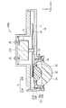
- FIG. 1 schematically shows an example of a cross-sectional configuration of a rotating body (phosphor wheel 10) constituting a light source device (light source device 100A) according to a first embodiment of the present disclosure and peripheral members thereof. is there.
- FIG. 2 is a perspective view of the configuration of the phosphor wheel 10 shown in FIG. 1 and its peripheral members
- FIG. 1 is a cross section along the line II shown in FIG. .
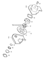
- FIG. 3 is an exploded perspective view of the phosphor wheel 10 and its peripheral members shown in FIGS.
- the light source device 100A is, for example, one configuring a projection type display device (projector) described later (see FIG. 5 and FIG. 6).
- the light source device 100A of the present embodiment has an adjustment mechanism (lens position adjustment mechanism) for adjusting the distance between the phosphor wheel 10 and the condensing lens group (for example, the condensing lenses 31, 32).
- the phosphor wheel 10 constituting the light source device 100A is housed in, for example, a housing (housing 21).
- a lens holding unit (lens that holds condensing lenses 31 and 32 for condensing excitation light EL emitted from a light source unit 110 described later (for example, see FIG. 5) toward the phosphor wheel 10 in the housing 21
- the holder 33 is fastened.
- the lens position adjustment mechanism of the present embodiment is configured of a housing 21 and a lens holder 33. More specifically, the lens position adjusting mechanism is provided on the side surface of the threading 33X provided in the fitting portion 33A of the lens holder 33 and the fitting opening 21H corresponding to the fitting portion 33A of the lens holder 33. It consists of a thread 21X, and these are fitted.
- the housing 21 and the lens holder 33 are fixed by, for example, a wave washer 36 disposed between the front portion of the housing 21 and the pressing portion 33B of the lens holder 33.
- the phosphor wheel 10 is, for example, a reflection type wavelength conversion element, and the phosphor layer 12 is provided on a wheel substrate 11 that can rotate around a rotation axis (for example, an axis 13J).
- the wheel substrate 11 is for supporting the phosphor layer 12 and has, for example, a disk shape.
- the wheel substrate 11 preferably has a function as a heat dissipation member, and is made of an inorganic material such as a metal material or a ceramic material which has a high thermal conductivity and can be mirror-polished.
- the wheel substrate 11 As a constituent material of the wheel substrate 11, for example, aluminum (Al), copper (Cu), molybdenum (Mo), tungsten (W), cobalt (Co), chromium (Cr), platinum (Pt), tantalum (Ta) And elemental metals such as lithium (Li), zirconium (Zr), ruthenium (Ru), rhodium (Rh) or palladium (Pd), or alloys containing one or more of these.
- an alloy such as CuW having a W content of 80 atomic% or more or CuMo having a Mo content of 40 atomic% or more can be used as a metal material for the wheel substrate 11.
- SiC silicon carbide
- AlN aluminum nitride
- BeO beryllium oxide
- SiC and Al a composite material of SiC and Al (However, the content of SiC is 50% And the above.
- the reflective film is formed of, for example, a metal film containing a metal element such as aluminum (Al), silver (Ag) or titanium (Ti), as well as a dielectric multilayer film.
- the reflection film functions to reflect the excitation light EL irradiated from the outside and the fluorescence FL from the phosphor layer 12 and to increase the luminous efficiency of the phosphor wheel 10.
- the wheel substrate 11 may not have light reflectivity.
- quartz or glass can be used besides crystalline materials such as single Si, SiC, diamond, sapphire and the like.
- an antireflective film be provided on the surface of the wheel substrate 11 opposite to the surface on which the phosphor layer 12 is formed.
- the phosphor layer 12 includes a plurality of phosphor particles, and is preferably formed in a plate shape, for example, and is formed of, for example, a so-called ceramic phosphor.
- the phosphor layer 12 is formed, for example, in an annular shape on the wheel substrate 11.
- the phosphor particles are particulate phosphors that absorb the excitation light EL emitted from the light source unit 110 and emit fluorescence FL.
- phosphor particles for example, fluorescence that is excited by blue laser light having a wavelength of blue wavelength range (for example, 400 nm to 470 nm) and emits yellow fluorescence (light of wavelength range between red wavelength range and green wavelength range) Substances are used.
- YAG yttrium aluminum garnet
- the average particle diameter of the phosphor particles is, for example, 5 ⁇ m or more and 40 ⁇ m or less, and the thickness of the phosphor layer 12 is preferably formed, for example, in a thickness of 40 ⁇ m or more and 200 ⁇ m or less.
- the motor 13 is for rotating and driving the phosphor wheel 10 at a predetermined rotation number.
- the motor 13 drives the phosphor wheel 10 so that the phosphor layer 12 rotates in a plane orthogonal to the irradiation direction of the excitation light EL emitted from the light source unit 110 described later.
- the irradiation position of the excitation light EL of the phosphor wheel 10 temporally changes (moves) at a speed corresponding to the number of rotations in a plane orthogonal to the irradiation direction of the excitation light.
- the motor 13 is fixed to the rear surface of the housing 21 and the rear cover 21 B by, for example, a screw 25.
- the housing 21 is for housing the phosphor wheel 10.
- the housing 21 includes, for example, a front cover 21A that covers the front of the phosphor wheel 10, and a rear cover 21B that covers the back of the phosphor wheel 10 and supports the motor 13 that drives the phosphor wheel 10.
- the front cover 21A is provided with a fitting opening 21H to which the lens holder 33 holding the condenser lenses 31 and 32 is fitted as described above, and a threading 21X is formed on the side surface of the opening 21H. It is done.
- the casing 21 is provided with an inlet 22 and an outlet 23 for cooling air for cooling the phosphor wheel 10 sent from a cooling fan (not shown) separately disposed.
- the housing 21 is preferably made of, for example, a material having a low coefficient of thermal expansion.
- the condensing lenses 31 and 32 are, for example, condensing lenses from the light source unit 110 side, for example, on the light path of the excitation light EL1 emitted from the light source unit 110 at a position facing the phosphor layer 12 of the phosphor wheel 10 31 and the condenser lens 32 are arranged in this order (in FIG. 5, they are shown as the condenser optical system 113).
- the condensing lens 31 condenses the excitation light EL from the light source unit 110 toward the condensing lens 32.
- the condensing lens 32 condenses the excitation light EL1 incident through the condensing lens 31 on the phosphor layer 12.
- the condensing lens 32 is configured to emit the fluorescence FL emitted from the phosphor layer 12 toward the condensing lens 31.
- the condenser lens 31 has, for example, an outer diameter larger than that of the condenser lens 32.
- the outer peripheral portions of the condenser lenses 31 and 32 are held by the lens holder 33 by the lens holding plates 34 and 35, respectively.
- the lens holder 33 is for holding the condenser lenses 31 and 32 as described above.
- the lens holder 33 has a fitting portion 33A that fits into the opening 21H of the housing 21.
- a threading 33X corresponding to the threading 21X provided on the side surface of the opening 21H of the housing 21 is formed on the entire surface, for example.
- the lens holder 33 is preferably made of, for example, a material having a low coefficient of thermal expansion.
- the distance between the phosphor layer 12 and the condenser lenses 31 and 32 can be adjusted. Specifically, by fitting the fitting portion 33A having the threading 33X corresponding to the threading 21X to the side 21 in the opening 21H having the threading 21X on the side, and rotating the lens holder 33, the distance in the Z axis direction Can be finely adjusted (for example, about 10 ⁇ m). Thus, the distance between the phosphor layer 12 and the focusing lenses 31 and 32 can be adjusted more precisely and precisely.
- a wave washer 36 is disposed between the front portion of the housing 21 and the pressing portion 33B of the lens holder 33.
- pressure is always applied in a fixed direction between the front portion of the housing 21 and the pressing portion 33B of the lens holder 33, and the position of the fitting portion 33A is fixed.
- the distance between the layer 12 and the focusing lenses 31, 32 is fixed. Therefore, positional deviation due to loosening or the like of the lens holder 33 which may be caused by vibration or the like due to rotation of the phosphor wheel 10 is suppressed.
- an uneven structure may be formed on the outer peripheral portion of the pressing portion 33B of the lens holder 33.
- the concavo-convex structure for example, when adjusting the distance between the phosphor layer 12 and the condensing lenses 31 and 32 using the jig 71, the point of action becomes far, and the action distance with respect to the feed amount can be increased. become. Therefore, the minute feeding of the lens holder 33 becomes easy, and the fine adjustment of the distance between the phosphor layer 12 and the focusing lenses 31 and 32, for example, about several hundred ⁇ m becomes possible.
- the lens holder 33 may be rotated using a piezoelectric element, a coil, or a micrometer. As a result, the distance between the phosphor layer 12 and the focusing lenses 31 and 32 can be easily adjusted more finely.
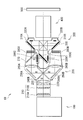
- FIG. 5 is a schematic diagram showing the entire configuration of the light source device 100A.
- the light source device 100A includes a phosphor wheel 10, a light source unit 110, condensing optical systems 111 and 113, and a dichroic mirror 112.
- the members constituting the light source device 100A excluding the light source unit 110 are disposed on the light path of light (FL) emitted from the phosphor wheel 10 in the order of the condensing optical system 113 and the dichroic mirror 112 from the phosphor wheel 10 side. It is done.
- the light source unit 110 is disposed at a position facing the dichroic mirror 112 with the focusing optical system 111 in between in the direction orthogonal to the light path of the fluorescence FL.
- the light source unit 110 has a solid light emitting element that emits light of a predetermined wavelength.
- a semiconductor laser element that oscillates excitation light EL for example, blue laser light having a wavelength of 445 nm or 455 nm
- the light source unit 110 emits the excitation light EL. Ru.
- the excitation light EL of a predetermined output may be obtained by one semiconductor laser element, but light emitted from a plurality of semiconductor laser elements is multiplexed.
- the excitation light EL of a predetermined output may be obtained.
- the wavelength of the excitation light EL is not limited to the above numerical value, and any wavelength can be used as long as it is a wavelength within the wavelength band of light called blue light.
- the condensing optical system 111 condenses the excitation light EL emitted from the light source unit 110 to a predetermined spot diameter and emits it toward the dichroic mirror 112.
- the dichroic mirror 112 selectively reflects light in a predetermined wavelength range, and selectively transmits light in other wavelength ranges. Specifically, the dichroic mirror 112 reflects the blue light (excitation light EL) emitted from the light source unit 110 in the direction of the focusing optical system 113, and transmits the focusing optical system 113 from the phosphor wheel 10.
- the incident yellow light (fluorescent light FL) is split into red light R and green light G to be incident on the illumination optical system 200 (described later).
- the condensing optical system 113 condenses the excitation light EL reflected by the dichroic mirror 112 to a predetermined spot diameter, and emits the collected excitation light EL toward the phosphor wheel 10. Further, the condensing optical system 113 is for emitting the fluorescence FL emitted from the phosphor wheel 10 toward the dichroic mirror 112.
- the condensing optical system 113 is configured using the condensing lenses 31 and 32 described above.
- the configuration of the light source device 100A shown in FIG. 5 is an example, and the present invention is not limited to this.
- a polarization-type light source device in which, for example, a 1 ⁇ 4 wavelength plate or the like is disposed between the light source unit 110 and the phosphor wheel 10 may be configured.
- FIG. 6 is a schematic diagram showing the entire configuration of a projector 1 including the light source device 100A shown in FIG. 5 as a light source optical system.
- a projector of a reflection type 3 LCD system in which light modulation is performed by a reflection type liquid crystal panel (LCD) will be described as an example.
- the phosphor wheel 10 can also be applied to a projector using a transmissive liquid crystal panel, a digital micro mirror device (DMD: Digital Micro-mirror Device) or the like instead of the reflective liquid crystal panel.
- DMD Digital Micro-mirror Device
- the projector 1 sequentially includes the light source device 100A, the illumination optical system 200, the image forming unit 300, and the projection optical system 400 (projection optical system) described above.
- the illumination optical system 200 includes, for example, a fly eye lens 210 (210A, 210B), a polarization conversion element 220, a lens 230, dichroic mirrors 240A, 240B, and reflection mirrors 250A, 250B from a position close to the light source device 100A. It has lenses 260A and 260B, a dichroic mirror 270, and polarizing plates 280A to 280C.
- the fly's eye lenses 210 are intended to homogenize the illuminance distribution of the white light from the light source device 100A.
- the polarization conversion element 220 functions to align the polarization axis of the incident light in a predetermined direction. For example, light other than P polarized light is converted to P polarized light.
- the lens 230 condenses the light from the polarization conversion element 220 toward the dichroic mirrors 240A and 240B.
- the dichroic mirrors 240A and 240B selectively reflect light in a predetermined wavelength range and selectively transmit light in other wavelength ranges.
- the dichroic mirror 240A mainly reflects red light in the direction of the reflection mirror 250A.
- the dichroic mirror 240B mainly reflects blue light in the direction of the reflection mirror 250B. Therefore, the green light mainly passes through both of the dichroic mirrors 240A and 240B, and travels to the reflective polarizing plate 310C (to be described later) of the image forming unit 300.
- the reflecting mirror 250A reflects the light (mainly red light) from the dichroic mirror 240A toward the lens 260A, and the reflecting mirror 250B reflects the light (mainly blue light) from the dichroic mirror 240B toward the lens 260B Do.
- the lens 260A transmits the light (mainly red light) from the reflection mirror 250A and focuses the light on the dichroic mirror 270.
- the lens 260 B transmits the light (mainly blue light) from the reflection mirror 250 B and condenses the light on the dichroic mirror 270.
- the dichroic mirror 270 selectively reflects green light and selectively transmits light in other wavelength ranges.
- the red light component of the light from the lens 260A is transmitted.
- the green light component is reflected toward the polarizing plate 280C.
- the polarizing plates 280A to 280C each include a polarizer having a polarization axis in a predetermined direction. For example, when the polarization conversion element 220 converts light into P-polarization, the polarizing plates 280A to 280C transmit the light of P-polarization and reflect the light of S-polarization.
- the image forming unit 300 includes reflective polarizing plates 310A to 310C, reflective liquid crystal panels 320A to 320C (light modulation elements), and a dichroic prism 330.
- the reflective polarizing plates 310A to 310C transmit light (for example, P-polarized light) having the same polarization axis as the polarization axis of polarized light from the polarizing plates 280A to 280C, and light (S-polarized light) having the other polarization axes It is a reflection.
- the reflective polarizing plate 310A transmits P-polarized red light from the polarizing plate 280A in the direction of the reflective liquid crystal panel 320A.
- the reflective polarizing plate 310B transmits P-polarized blue light from the polarizing plate 280B in the direction of the reflective liquid crystal panel 320B.
- the reflective polarizing plate 310C transmits the P-polarized green light from the polarizing plate 280C in the direction of the reflective liquid crystal panel 320C.
- the P-polarized green light transmitted through both the dichroic mirrors 240A and 240B and incident on the reflective polarizing plate 310C passes through the reflective polarizing plate 310C and is incident on the dichroic prism 330 as it is.
- the reflective polarizing plate 310A reflects the S-polarized red light from the reflective liquid crystal panel 320A and causes the light to be incident on the dichroic prism 330.
- the reflective polarizing plate 310 ⁇ / b> B reflects the blue light of S-polarization from the reflective liquid crystal panel 320 ⁇ / b> B and makes the blue light enter the dichroic prism 330.
- the reflective polarizing plate 310 ⁇ / b> C reflects the green light of S-polarization from the reflective liquid crystal panel 320 ⁇ / b> C and causes the green light to be incident on the dichroic prism 330.
- the reflective liquid crystal panels 320A to 320C perform spatial modulation of red light, blue light or green light, respectively.
- the dichroic prism 330 combines the incident red light, blue light and green light, and emits the light toward the projection optical system 400.
- the projection optical system 400 has, for example, a plurality of lenses and the like although not shown.
- the projection optical system 400 enlarges the light emitted from the image forming unit 300 and projects the light onto the screen 500.
- the lens position adjustment mechanism capable of minute adjustment by providing the lens position adjustment mechanism capable of minute adjustment, the phosphor layer 12 provided on the phosphor wheel 10, and the condensing lens group (condenser lens 31 , 32) were controlled.
- the casing 21 for accommodating the phosphor wheel 10 and the lens holder 33 for holding the condenser lenses 31 and 32 are provided with threadings 21X and 33X fitted to each other.
- the housing 21 housing the phosphor wheel 10 and the lens holder 33 holding the condenser lenses 31 and 32 are screwed 21X and 33X to be fitted to each other.
- the lens holder 33 is fastened to the housing 21, for example, by adjusting the amount of rotation of the lens holder 33, it is possible to finely adjust the lens position.
- the relative positions of the phosphor layer 12 and the condenser lenses 31 and 32 are optimized, and it is possible to provide the light source device 100A having high luminance and the projector 1 including the light source device 100A.
- the distance between the phosphor layer 12 and the condenser lenses 31 and 32 is mechanically adjusted as described above, it becomes possible to absorb the variation of parts, and thus the phosphor It becomes possible to easily optimize the relative position of the layer 12 and the focusing lenses 31 and 32.
- the condensing lenses 31 and 32 can be adjusted to the best relative position with respect to the phosphor layer 12, so that the cost can be reduced. .
- the wave washer 36 is disposed between the housing 21 and the pressing portion 33B of the lens holder 33, the light is collected at the best relative position to the phosphor layer 12 It becomes possible to easily fix the lenses 31 and 32.
- the pressure by the wave washer 36 is always applied in a fixed direction, it is not susceptible to backlash, and since it is fixed by pressure, the lens position can be easily readjusted. It becomes.
- FIG. 7 represents typically the cross-sectional structure of the fluorescent substance wheel 10 which comprises the light source device 100B which concerns on the modification (modification 1) of 1st Embodiment of this indication, and its periphery member.
- the light source device 100B constitutes, for example, the projector 1.
- the lock nut 37 is disposed between the housing 21 and the pressing portion 33B of the lens holder 33, and the lock nut 37 positions the lens positions of the focusing lenses 31 and 32 with respect to the phosphor layer 12. The point of fixing after adjustment is different from the first embodiment.
- the lock nut 37 In the lens position adjusting mechanism using the lock nut 37, after adjusting the lens position of the condenser lenses 31 and 32 with respect to the phosphor layer 12, the lock nut 37 is rotated to abut the housing 21 by screwing the lens holder 33. Pressure is applied to 33X and fixed. Further, since the pressure is fixed, the lens position can be easily re-adjusted as in the case of using the wave washer 36.
- FIG. 8 schematically shows a cross-sectional configuration of a phosphor wheel 10 and its peripheral members that constitute a light source device 100C according to a modified example (modified example 2) of the first embodiment of the present disclosure.
- the light source device 100C constitutes, for example, the projector 1 as in the light source device 100A.
- the light source device 100C of the present modification is different from the first embodiment in that fixing of the condenser lenses 31 and 32 after adjusting the lens position with respect to the phosphor layer 12 is performed by the set screw 24.
- the set screw 24 attached to the side surface of the opening 21H of the housing 21 is rotated to open the opening 21H.
- the pressure is applied to the lens holder 33 to fix the lens holder 33 by abutting against the side surface of the lens holder 33 inserted into the lens holder 33.
- FIG. 9 schematically shows a cross-sectional configuration of a phosphor wheel 10 and its peripheral members that constitute a light source device 100D according to a modification (Modification 3) of the first embodiment of the present disclosure.
- the light source device 100D constitutes, for example, the projector 1 in the same manner as the light source device 100A.
- the light source device 100D of the present modified example is different from the first embodiment in that an adhesive 38 is used for fixing the lens positions of the focusing lenses 31 and 32 to the phosphor layer 12 after the lens position adjustment.
- the lens position adjusting mechanism using the adhesive 38 After the lens position adjustment of the condenser lenses 31, 32 with respect to the phosphor layer 12, the side surface of the opening 21H of the housing 21 and the side surface of the fitting portion 33A of the lens holder 33 are By bonding with the adhesive 38, the positions of the condenser lenses 31, 32 with respect to the phosphor layer 12 are fixed.
- FIG. 10 schematically shows a cross-sectional configuration of a phosphor wheel 10 and its peripheral members that constitute a light source device 100I according to a modified example (modified example 4) of the first embodiment of the present disclosure.
- the light source device 100I constitutes, for example, the projector 1 in the same manner as the light source device 100A.
- the lens position adjustment mechanism includes the housing 61 and the motor holder 63 in which the motor 13 of the phosphor wheel 10 is fixed by, for example, the fixing screw 65. It differs from the first embodiment.
- the lens position adjusting mechanism is constituted by threadings 61X and 63X respectively provided on the rear cover 61B of the housing 61 and the motor holder 63 attached to the rear cover 61B of the housing 61. It is supposed to fit. Further, a wave washer 66 is disposed between the rear cover 61B and the motor holder 63, specifically, between the pressing portion 61Ba of the rear cover 61B facing each other and the pressing portion 63A of the motor holder 63. The distance between the phosphor wheel 10 and the focusing lenses 31 and 32 is fixed.
- the housing 61 includes, for example, a front cover 61A that covers the front surface of the phosphor wheel 10, and a rear cover 61B that covers a portion of the rear surface of the phosphor wheel 10.
- the rear cover 61B is provided with a fitting opening 61H into which the motor holder 63 is fitted, and a threading 61X is formed on the side surface thereof.
- the motor holder 63 is also fitted in the opening 61H, and the phosphor wheel 10 connected to the motor 13 is moved in the Z-axis direction by rotating the motor holder 63.
- the rear cover 61B of the housing 61 is provided with the openings 61H in which the motor holder 63 is fitted, and the side surfaces are provided with the threadings 61X and 63X fitted together.
- the motor holder 63 is fitted in the opening 61H and rotated to move the phosphor wheel 10 in the Z-axis direction, and the relative position between the phosphor layer 12 and the condenser lenses 31, 32 Optimization is possible.
- the wave washer 66 is disposed between the pressing portions 61Ba and 63A provided on the rear cover 61B and the motor holder 63, the focusing lens 31 at the best relative position with respect to the phosphor layer 12, It becomes possible to easily fix 32. Therefore, the present modification has the same effect as the light source device 100A in the first embodiment.
- FIG. 11 schematically shows an example of a cross-sectional configuration of a rotating body (phosphor wheel 10) constituting a light source device (light source device 100E) according to a second embodiment of the present disclosure and peripheral members thereof. is there.
- FIG. 12 is a perspective view of the configuration of the phosphor wheel 10 and its peripheral members shown in FIG. 11 from the rear side
- FIG. 11 is a cross section along line II-II shown in FIG. It is a thing.
- FIG. 13 is an exploded perspective view of the phosphor wheel 10 and its peripheral members shown in FIGS. 11 and 12.
- the light source device 100E constitutes, for example, the projector 1.
- the lens position adjustment mechanism is configured of a threading 51X provided on the motor holder 51, and a feed screw 52 having a threading 52X corresponding to the threading 51X. It is.
- the phosphor wheel 10 constituting the light source device 100E is housed together with the motor 13 in a motor housing portion 41C of the housing 41, for example.
- a motor holder 51 that supports the motor 13 and holds the motor 13 in the housing 41 is attached to the motor 13.
- the motor holder 51 and the motor housing portion 41C are in a fitting relationship, whereby the motor holder 51 can move in the motor housing portion 41C in a direction perpendicular to the optical axis (for example, the Z-axis direction). There is.
- the motor holder 51 is provided with an opening 51H having a threading 51X on the side surface, and the feed screw 52 fitted with the opening 51H and provided with a threading 52X corresponding to the threading 51X.
- the motor holder 51 moves in the motor housing 41C to adjust the distance between the condenser lenses 31, 32 and the phosphor wheel 10 having the phosphor layer 12 Be done.
- the housing 41 includes, for example, a front cover 41A that covers the front surface of the phosphor wheel 10, and a rear cover 41B that covers the back surface of the phosphor wheel 10.
- condenser lenses 31 and 32 are integrated with the front cover 41A.
- the rear cover 41B is provided with the motor housing portion 41C for housing the motor holder 51.
- the motor housing portion 41C internally has a guide portion 41G for housing the motor holder 51 and guiding the movement of the motor holder 51 in the Z-axis direction. Specifically, the guide portion 41G (inner diameter of the motor housing portion 41C) is fitted to the outer diameter (outer side surface) of the motor holder 51.
- the motor holder 51 can be moved only in the Z-axis direction, and the deviation of the irradiation position of the excitation light EL in the planar direction is suppressed.
- the motor housing portion 41C of the rear cover 41B is provided with an opening 41H into which the feed screw 52 is inserted. Further, as in the case 21 in the first embodiment, the case 41 is provided with an inlet 42 and an outlet 43 for cooling air for cooling the phosphor wheel 10.
- the motor holder 51 is for holding the motor 13 that drives the phosphor wheel 10, and the motor 13 is fixed to the motor holder 51 by, for example, a fixing screw 55.
- the outer diameter (outside surface) of the motor holder 51 is fitted as a guided portion 51G with the guide portion 41G of the motor housing portion 41C. That is, in the light source device 100E of the present embodiment, the motor holder 51 is accommodated in the motor accommodating portion 41C of the housing 41, whereby the movement of the motor holder 51 is in the direction orthogonal to the optical axis (for example, the Z axis direction). Only possible.
- An opening 51 H is provided on the back of the motor holder 51.
- the opening 51H is engaged with the feed screw 52 for moving the motor holder 51 in the Z-axis direction in the motor housing 41C, and the side surface of the opening 51H is a thread 52X formed in the feed screw 52. A corresponding threading 51X is provided.
- a wave washer 53 is disposed between the rear surface of the motor holder 51 and the rear cover 41 B in the housing 41.
- the lens position adjustment mechanism of the present embodiment is constituted by threading 51X and 52X provided on the side surface of the opening 51H and the side surface of the feed screw 52, respectively.
- the motor holder 51 is moved along the side surface of the motor housing portion 41C by rotating the feed screw 52, for example, using the jig 72 in the arrow direction shown in FIGS. 12 and 14, for example. Do.
- the phosphor wheel 10 connected to the motor 13 moves, for example, in the Z-axis direction, and the minute adjustment of the distance between the phosphor layer 12 on the phosphor wheel 10 and the focusing lenses 31 and 32 is performed. Is possible.
- a wave washer 53 is disposed between the rear surface of the motor holder 51 and the rear cover 41B in the housing 41.
- the phosphor layer 12 and the condensing lens after the lens position adjustment is performed by the wave washer 53.
- the distance between 31 and 32 is fixed. Therefore, positional deviation of the motor holder 51 which may be caused by vibration or the like due to the rotation of the phosphor wheel 10 is suppressed.
- the housing 41 is provided with the motor storage portion 41C, and the motor holder 51 moves, for example, in the Z-axis direction along the side surface of the motor storage portion 41C. I did it.
- the rear surface of the motor holder 51 is provided with an opening 51H fitted with a feed screw 52 for moving the motor holder 51 in the Z-axis direction in the motor housing 41C.
- the side surfaces of the opening 51H and the feed screw 52 are provided with mutually corresponding threadings, and the motor holder 51 is formed on the side surface of the motor housing 41C by rotating the feed screw 52 from the outside of the housing 41, for example. Move along.
- the light source device 100E according to the present embodiment exhibits the same effect as the light source device 100A according to the first embodiment.
- the wave washer 53 is disposed between the rear surface of the motor holder 51 and the rear cover 41B in the housing 41, the fluorescence is the same as in the first embodiment. It is possible to easily fix the focusing lenses 31 and 32 at the best relative position to the body layer 12.
- FIG. 15 schematically shows a cross-sectional configuration of the phosphor wheel 10 and its peripheral members that constitute a light source device 100F according to a modification (Modification 5) of the second embodiment of the present disclosure. Similar to the light source device 100A, the light source device 100F constitutes, for example, the projector 1. In the light source device 100F of the present modification, the lock nut 57 is disposed between the housing 41 and the feed screw 52, and the lock nut 57 fixes the phosphor layer 12 to the condensing lenses 31 and 32 after adjusting the lens position.
- the second embodiment differs from the second embodiment in that
- the feed screw 52 is rotated by rotating the lock nut 57 to abut the rear cover 41 B of the housing 41 after adjusting the lens position of the condenser lenses 31 and 32 with respect to the phosphor layer 12.
- the pressure is applied to and fixed to the screw 52X.
- the lens position can be easily readjusted as in the case of using the wave washer 53.
- FIG. 16 represents typically the cross-sectional structure of the fluorescent substance wheel 10 which comprises the light source device 100G which concerns on the modification (modification 6) of 2nd Embodiment of this indication, and its periphery member.
- the light source device 100G constitutes, for example, the projector 1 in the same manner as the light source device 100A.
- the light source device 100G of this modification is different from the second embodiment in that fixing of the phosphor layer 12 to the condenser lenses 31 and 32 after adjusting the lens position is performed by the set screw 54.
- the set screw 54 attached to the side surface of the motor housing portion 41C of the housing 41 is rotated.
- pressure is applied to the motor holder 51 and fixed.
- FIG. 17 schematically shows a cross-sectional configuration of a phosphor wheel 10 and its peripheral members that constitute a light source device 100H according to a modified example (modified example 7) of the second embodiment of the present disclosure.
- the light source device 100H constitutes, for example, the projector 1 as in the light source device 100A.
- the light source device 100H of this modification is different from the second embodiment in that an adhesive 58 is used for fixing the phosphor layer 12 to the condenser lenses 31 and 32 after adjusting the lens position.
- the motor holder 51 is adhered by the adhesive 58 in the motor housing portion 41C, The position of the phosphor layer 12 with respect to the lenses 31 and 32 is fixed.
- the wave washers 36 and 53 are used for fixing after adjusting the lens position, but a member having a spring property such as a cor spring or a locking washer may be used. It is possible to replace it.
- Such members include, for example, a spring washer, a disc spring washer and a nort lock washer.
- the lock nuts 37 and 57 were used for fixation after lens position adjustment, it is possible to replace with a wedge nut.
- apparatuses other than the above-described projector may be configured as a projection display apparatus according to the present technology.
- a projector of a reflection type 3 LCD system using a reflection type liquid crystal panel as a light modulation element has been described, but the present invention is not limited thereto.
- the present invention can also be applied to so-called transmissive 3 LCD projectors.
- an example using a reflection type phosphor wheel is shown as an example of the phosphor wheel of the present disclosure, but the technology of the present disclosure is, for example, a transmission type phosphor wheel Is also applicable.
- the present technology can also be configured as follows.
- a light source unit A rotating body having a phosphor that emits fluorescence upon being excited by excitation light from the light source unit;
- a motor for driving the rotating body;
- a housing for accommodating the rotating body;
- At least one lens group configured to focus excitation light from the light source unit toward the rotating body;
- a lens holding unit that holds the lens unit;
- a light source device comprising: an adjusting mechanism that adjusts a distance between the rotating body and the lens group.
- the light source device wherein the adjustment mechanism is configured by the housing and the motor holding unit. (9) And a motor holding unit for holding the motor, and a feed screw for feeding the motor holding unit.
- the motor holding portion has a feed screw opening corresponding to the feed screw,
- the light source device wherein the adjustment mechanism is configured by threading provided in the feed screw and the feed screw opening.
- the light source device (10)
- the light source device (9)
- the lens holding unit is integrated with the housing.
- the housing includes a motor accommodating portion that accommodates the motor holding portion.
- the motor housing portion has a guide portion for guiding the moving direction of the motor holding portion inside.
- the light source device according to (9) or (10), wherein the motor holding portion has a guided portion fitted to the guide portion on the side surface.
- a light source device A light modulation element that modulates light emitted from the light source device; A projection optical system for projecting light from the light modulation element;
- the light source device A light source unit, A rotating body having a phosphor that emits fluorescence upon being excited by excitation light from the light source unit;
- a motor for driving the rotating body;
- a housing for accommodating the rotating body;
- At least one lens group configured to focus excitation light from the light source unit toward the rotating body;
- a lens holding unit that holds the lens unit;
- An adjustment mechanism for adjusting a distance between the rotating body and the lens group.
Landscapes
- Physics & Mathematics (AREA)
- Engineering & Computer Science (AREA)
- General Engineering & Computer Science (AREA)
- General Physics & Mathematics (AREA)
- Optics & Photonics (AREA)
- Spectroscopy & Molecular Physics (AREA)
- Multimedia (AREA)
- Astronomy & Astrophysics (AREA)
- Signal Processing (AREA)
- Projection Apparatus (AREA)
- Transforming Electric Information Into Light Information (AREA)
- Devices For Indicating Variable Information By Combining Individual Elements (AREA)
Abstract
Description
1.第1の実施の形態(レンズ保持部および筐体に設けられたネジ切りとウェーブワッシャとによって構成されるレンズ位置調整機構を有する光源装置)
1-1.レンズ位置調整機構の構成
1-2.光源装置の構成
1-3.プロジェクタの構成
1-4.作用・効果
2.変形例
2-1.変形例1(ネジ切りおよびロックナットによって構成されるレンズ位置調整機構の例)
2-2.変形例2(ネジ切りおよび止めネジによって構成されるレンズ位置調整機構の例)
2-3.変形例3(ネジ切りおよび接着材によって構成されるレンズ位置調整機構の例)
2-4.変形例4(モータ保持部および筐体に設けられたネジ切りとウェーブワッシャとによって構成されるレンズ位置調整機構の例)
3.第2の実施の形態(モータ保持部に設けられたネジ切りおよび送りネジとウェーブワッシャとによって構成されるレンズ位置調整機構の例)
3-1.レンズ位置調整機構の構成
3-2.作用・効果
4.変形例
4-1.変形例5(ネジ切りおよび送りネジとロックナットとによって構成されるレンズ位置調整機構の例)
4-2.変形例6(ネジ切りおよび送りネジと止めネジとによって構成されるレンズ位置調整機構の例)
4-3.変形例7(ネジ切りおよび送りネジと接着材とによって構成されるレンズ位置調整機構の例)
図1は、本開示の第1の実施の形態に係る光源装置(光源装置100A)を構成する回転体(蛍光体ホイール10)およびその周辺部材の断面構成の一例を模式的に表したものである。図2は、図1に示した蛍光体ホイール10およびその周辺部材の構成を斜視的に表したものであり、図1は、図2に示したI-I線における断面を表したものである。図3は、図1および図2に示した蛍光体ホイール10およびその周辺部材を分解して斜視的に表したものである。この光源装置100Aは、例えば、後述する投射型表示装置(プロジェクタ)を構成するもの(図5および図6参照)である。本実施の形態の光源装置100Aは、蛍光体ホイール10と、集光レンズ群(例えば、集光レンズ31,32)との距離を調整する調整機構(レンズ位置調整機構)を有するものである。
光源装置100Aを構成する蛍光体ホイール10は、例えば、筐体(筐体21)に収容されている。筐体21には、後述する光源部110(例えば、図5参照)から出射される励起光ELを蛍光体ホイール10に向けて集光する集光レンズ31,32を保持するレンズ保持部(レンズホルダ33)が締結されている。本実施の形態のレンズ位置調整機構は、筐体21とレンズホルダ33とから構成されている。より詳細には、レンズ位置調整機構は、レンズホルダ33の嵌合部33Aに設けられたネジ切り33Xと、レンズホルダ33の嵌合部33Aに対応する嵌合用の開口21Hの側面に設けられたネジ切り21Xとから構成されており、これらは嵌合するようになっている。筐体21とレンズホルダ33とは、例えば、筐体21のフロント部と、レンズホルダ33の押え部33Bとの間に配置されたウェーブワッシャ36によって固定される。
図5は、光源装置100Aの全体構成を表す概略図である。光源装置100Aは、蛍光体ホイール10と、光源部110と、集光光学系111,113と、ダイクロイックミラー112とを有する。光源部110を除く光源装置100Aを構成する各部材は、蛍光体ホイール10側から集光光学系113、ダイクロイックミラー112の順に、蛍光体ホイール10から出射される光(FL)の光路上に配置されている。光源部110は、蛍光FLの光路と直交する方向で、集光光学系111を間に、ダイクロイックミラー112に対向する位置に配置されている。
次に、本開示の投射型表示装置(プロジェクタ1)について説明する。図6は、図5に示した光源装置100Aを光源光学系として備えたプロジェクタ1の全体構成を表した概略図である。なお、以下では、反射型の液晶パネル(LCD)により光変調を行う反射型3LCD方式のプロジェクタを例示して説明する。なお、蛍光体ホイール10は、反射型液晶パネルの代わりに、透過型液晶パネルやデジタル・マイクロミラー・デバイス(DMD:Digital Micro-mirror Device)等を用いたプロジェクタにも適用され得る。
前出したように、プロジェクタには、光源から出射される光の光路上に様々なレンズが配置されている。このうち、光源から出射される光を蛍光体上に集光する集光レンズ群と蛍光体との相対位置はプロジェクタの輝度に対して特に大きな影響を及ぼす。一般的なプロジェクタでは、部品精度を上げることで輝度の向上が図られている。しかしながら、部品精度によるプロジェクタの輝度の管理は、部品のばらつきによる輝度の低下が起こりやすい。また、コストを増加させることに繋がる。また、蛍光体の表面は凹凸を有するため、プロジェクタの輝度を部品寸法で管理することは困難であった。
(2-1.変形例1)
図7は、本開示の第1の実施の形態の変形例(変形例1)に係る光源装置100Bを構成する蛍光体ホイール10およびその周辺部材の断面構成を模式的に表したものである。この光源装置100Bは、上記光源装置100Aと同様に、例えば、プロジェクタ1を構成するものである。本変形例の光源装置100Bでは、筐体21とレンズホルダ33の押え部33Bとの間にロックナット37を配置し、このロックナット37によって蛍光体層12に対する集光レンズ31,32のレンズ位置調整後の固定を行う点が上記第1の実施の形態とは異なる。
図8は、本開示の第1の実施の形態の変形例(変形例2)に係る光源装置100Cを構成する蛍光体ホイール10およびその周辺部材の断面構成を模式的に表したものである。この光源装置100Cは、上記光源装置100A等と同様に、例えば、プロジェクタ1を構成するものである。本変形例の光源装置100Cでは、蛍光体層12に対する集光レンズ31,32のレンズ位置調整後の固定を、止めネジ24によって行う点が上記第1の実施の形態とは異なる。
図9は、本開示の第1の実施の形態の変形例(変形例3)に係る光源装置100Dを構成する蛍光体ホイール10およびその周辺部材の断面構成を模式的に表したものである。この光源装置100Dは、上記光源装置100A等と同様に、例えば、プロジェクタ1を構成するものである。本変形例の光源装置100Dでは、蛍光体層12に対する集光レンズ31,32のレンズ位置調整後の固定に接着材38を用いる点が上記第1の実施の形態とは異なる。
図10は、本開示の第1の実施の形態の変形例(変形例4)に係る光源装置100Iを構成する蛍光体ホイール10およびその周辺部材の断面構成を模式的に表したものである。この光源装置100Iは、上記光源装置100A等と同様に、例えば、プロジェクタ1を構成するものである。本変形例の光源装置100Iでは、レンズ位置調整機構が、筐体61と、蛍光体ホイール10のモータ13が、例えば固定ネジ65によって固定されたモータホルダ63とから構成されている点が上記第1の実施の形態とは異なる。
図11は、本開示の第2の実施の形態に係る光源装置(光源装置100E)を構成する回転体(蛍光体ホイール10)およびその周辺部材の断面構成の一例を模式的に表したものである。図12は、図11に示した蛍光体ホイール10およびその周辺部材の構成を背面側から斜視的に表したものであり、図11は、図12に示したII-II線における断面を表したものである。図13は、図11および図12に示した蛍光体ホイール10およびその周辺部材を分解して斜視的に表したものである。この光源装置100Eは、上記光源装置100Aと同様に、例えば、プロジェクタ1を構成するものである。本実施の形態の光源装置100Eは、レンズ位置調整機構が、モータホルダ51に設けられたネジ切り51Xと、このネジ切り51Xに対応するネジ切り52Xを備えた送りネジ52とから構成されたものである。
光源装置100Eを構成する蛍光体ホイール10は、例えば、筐体41のモータ収容部41Cにモータ13と共に収容されている。本実施の形態では、モータ13には、モータ13を支持すると共に、筐体41内においてモータ13を保持するモータホルダ51が取り付けられている。このモータホルダ51とモータ収容部41Cとは嵌合関係にあり、これにより、モータホルダ51がモータ収容部41C内を、光軸に対して直交方向(例えばZ軸方向)に移動可能となっている。詳細には、モータホルダ51には、側面にネジ切り51Xを有する開口51Hが設けられており、この開口51Hと嵌合すると共に、ネジ切り51Xに対応するネジ切り52Xが設けられた送りネジ52を、例えば筐体41の外側から回転させることによって、モータホルダ51がモータ収容部41C内を移動して、集光レンズ31,32と蛍光体層12を有する蛍光体ホイール10との距離が調整される。
以上のように、本実施の形態の光源装置100Eでは、筐体41に、モータ収容部41Cを設け、このモータ収容部41Cの側面に沿って、モータホルダ51が、例えばZ軸方向に移動するようにした。具体的には、モータホルダ51の背面には、モータ収容部41C内においてモータホルダ51をZ軸方向に移動させる送りネジ52と嵌合する開口51Hが設けられている。開口51Hの側面および送りネジ52には、互いに対応するネジ切りが設けられており、送りネジ52を、例えば筐体41の外側から回転させることによって、モータホルダ51がモータ収容部41Cの側面に沿って移動する。これにより、集光レンズ31,32に対して蛍光体層12を有する蛍光体ホイール10をZ軸方向に微小に調整することが可能となり、蛍光体層12と集光レンズ31,32との相対位置が最適化される。即ち、本実施の形態の光源装置100Eは、上記第1の実施の形態における光源装置100Aと同様の効果を奏する。
(4-1.変形例5)
図15は、本開示の第2の実施の形態の変形例(変形例5)に係る光源装置100Fを構成する蛍光体ホイール10およびその周辺部材の断面構成を模式的に表したものである。この光源装置100Fは、上記光源装置100Aと同様に、例えば、プロジェクタ1を構成するものである。本変形例の光源装置100Fでは、筐体41と送りネジ52との間にロックナット57を配置し、このロックナット57によって集光レンズ31,32に対する蛍光体層12のレンズ位置調整後の固定を行う点が上記第2の実施の形態とは異なる。
図16は、本開示の第2の実施の形態の変形例(変形例6)に係る光源装置100Gを構成する蛍光体ホイール10およびその周辺部材の断面構成を模式的に表したものである。この光源装置100Gは、上記光源装置100A等と同様に、例えば、プロジェクタ1を構成するものである。本変形例の光源装置100Gでは、集光レンズ31,32に対する蛍光体層12のレンズ位置調整後の固定を、止めネジ54によって行う点が上記第2の実施の形態とは異なる。
図17は、本開示の第2の実施の形態の変形例(変形例7)に係る光源装置100Hを構成する蛍光体ホイール10およびその周辺部材の断面構成を模式的に表したものである。この光源装置100Hは、上記光源装置100A等と同様に、例えば、プロジェクタ1を構成するものである。本変形例の光源装置100Hでは、集光レンズ31,32に対する蛍光体層12のレンズ位置調整後の固定に接着材58を用いる点が上記第2の実施の形態とは異なる。
(1)
光源部と、
前記光源部からの励起光により励起されて蛍光を発する蛍光体を有する回転体と、
前記回転体を駆動するモータと、
前記回転体を収容する筐体と、
前記光源部からの励起光を前記回転体に向けて集光する1以上のレンズ群と、
前記レンズ群を保持するレンズ保持部と、
前記回転体と前記レンズ群との距離を調整する調整機構と
を備えた光源装置。
(2)
前記調整機構は、前記筐体と前記レンズ保持部とによって構成されている、前記(1)に記載の光源装置。
(3)
前記レンズ保持部は、前記筐体との嵌合部を有し、前記筐体は、前記嵌合部に対応する嵌合用開口を有する、前記(1)または(2)に記載の光源装置。
(4)
前記調整機構は、前記嵌合部および前記嵌合用開口にそれぞれ設けられたネジ切りによって構成されている、前記(3)に記載の光源装置。
(5)
前記レンズ保持部と前記筐体とは、バネ性を有するワッシャ、ロックナット、接着材または止めネジにより固定されている、前記(1)乃至(4)のうちのいずれかに記載の光源装置。
(6)
前記バネ性を有するワッシャは、ウェーブワッシャ、バネ座金、皿バネ座金、ノルトロックワッシャ-のうちのいずれかである、前記(5)に記載の光源装置。
(7)
前記レンズ保持部は、外周部の側面に凹凸構造を有する、前記(1)乃至(6)のうちのいずれかに記載の光源装置。
(8)
更に、前記モータを保持するモータ保持部を備え、
前記調整機構は、前記筐体と前記モータ保持部とによって構成されている、前記(1)に記載の光源装置。
(9)
更に、前記モータを保持するモータ保持部と、前記モータ保持部を送り出す送りネジとを備え、
前記モータ保持部は、前記送りネジに対応する送りネジ用開口を有し、
前記調整機構は、前記送りネジおよび前記送りネジ用開口にそれぞれ設けられたネジ切りによって構成されている、前記(1)に記載の光源装置。
(10)
前記レンズ保持部は、前記筐体と一体化されている、前記(9)に記載の光源装置。
(11)
前記筐体は、前記モータ保持部を収容するモータ収容部を備え、
前記モータ収容部は、内部に前記モータ保持部の移動方向をガイドするガイド部を有し、
前記モータ保持部は、側面に前記ガイド部と嵌合する被ガイド部を有する、前記(9)または(10)に記載の光源装置。
(12)
前記モータ保持部と前記筐体とは、バネ性を有するワッシャ、ロックナット、接着材または止めネジにより固定されている、前記(9)乃至(11)のうちのいずれかに記載の光源装置。
(13)
前記バネ性を有するワッシャは、ウェーブワッシャ、バネ座金、皿バネ座金、ノルトロックワッシャ-のうちのいずれかである、前記(12)に記載の光源装置。
(14)
光源装置と、
前記光源装置から出射される光を変調する光変調素子と、
前記光変調素子からの光を投射する投射光学系とを備え、
前記光源装置は、
光源部と、
前記光源部からの励起光により励起されて蛍光を発する蛍光体を有する回転体と、
前記回転体を駆動するモータと、
前記回転体を収容する筐体と、
前記光源部からの励起光を前記回転体に向けて集光する1以上のレンズ群と、
前記レンズ群を保持するレンズ保持部と、
前記回転体と前記レンズ群との距離を調整する調整機構と
を有する投射型表示装置。
Claims (14)
- 光源部と、
前記光源部からの励起光により励起されて蛍光を発する蛍光体を有する回転体と、
前記回転体を駆動するモータと、
前記回転体を収容する筐体と、
前記光源部からの励起光を前記回転体に向けて集光する1以上のレンズ群と、
前記レンズ群を保持するレンズ保持部と、
前記回転体と前記レンズ群との距離を調整する調整機構と
を備えた光源装置。 - 前記調整機構は、前記筐体と前記レンズ保持部とによって構成されている、請求項1に記載の光源装置。
- 前記レンズ保持部は、前記筐体との嵌合部を有し、前記筐体は、前記嵌合部に対応する嵌合用開口を有する、請求項1に記載の光源装置。
- 前記調整機構は、前記嵌合部および前記嵌合用開口にそれぞれ設けられたネジ切りによって構成されている、請求項3に記載の光源装置。
- 前記レンズ保持部と前記筐体とは、バネ性を有するワッシャ、ロックナット、接着材または止めネジにより固定されている、請求項1に記載の光源装置。
- 前記バネ性を有するワッシャは、ウェーブワッシャ、バネ座金、皿バネ座金、ノルトロックワッシャ-のうちのいずれかである、請求項5に記載の光源装置。
- 前記レンズ保持部は、外周部の側面に凹凸構造を有する、請求項1に記載の光源装置。
- 更に、前記モータを保持するモータ保持部を備え、
前記調整機構は、前記筐体と前記モータ保持部とによって構成されている、請求項1に記載の光源装置。 - 更に、前記モータを保持するモータ保持部と、前記モータ保持部を送り出す送りネジとを備え、
前記モータ保持部は、前記送りネジに対応する送りネジ用開口を有し、
前記調整機構は、前記送りネジおよび前記送りネジ用開口にそれぞれ設けられたネジ切りによって構成されている、請求項1に記載の光源装置。 - 前記レンズ保持部は、前記筐体と一体化されている、請求項9に記載の光源装置。
- 前記筐体は、前記モータ保持部を収容するモータ収容部を備え、
前記モータ収容部は、内部に前記モータ保持部の移動方向をガイドするガイド部を有し、
前記モータ保持部は、側面に前記ガイド部と嵌合する被ガイド部を有する、請求項9に記載の光源装置。 - 前記モータ保持部と前記筐体とは、バネ性を有するワッシャ、ロックナット、接着材または止めネジにより固定されている、請求項9に記載の光源装置。
- 前記バネ性を有するワッシャは、ウェーブワッシャ、バネ座金、皿バネ座金、ノルトロックワッシャ-のうちのいずれかである、請求項12に記載の光源装置。
- 光源装置と、
前記光源装置から出射される光を変調する光変調素子と、
前記光変調素子からの光を投射する投射光学系とを備え、
前記光源装置は、
光源部と、
前記光源部からの励起光により励起されて蛍光を発する蛍光体を有する回転体と、
前記回転体を駆動するモータと、
前記回転体を収容する筐体と、
前記光源部からの励起光を前記回転体に向けて集光する1以上のレンズ群と、
前記レンズ群を保持するレンズ保持部と、
前記回転体と前記レンズ群との距離を調整する調整機構と
を有する投射型表示装置。
Priority Applications (5)
| Application Number | Priority Date | Filing Date | Title |
|---|---|---|---|
| US16/651,076 US11360370B2 (en) | 2017-10-05 | 2018-08-16 | Light source device and projection-type display |
| CN201880062999.9A CN111149054B (zh) | 2017-10-05 | 2018-08-16 | 光源装置和投射型显示器 |
| EP18864815.8A EP3693791A4 (en) | 2017-10-05 | 2018-08-16 | LIGHT SOURCE DEVICE AND PROJECTION-TYPE DISPLAY DEVICE |
| JP2019546557A JP7136115B2 (ja) | 2017-10-05 | 2018-08-16 | 光源装置および投射型表示装置 |
| US17/744,905 US11835848B2 (en) | 2017-10-05 | 2022-05-16 | Light source device and projection-type display |
Applications Claiming Priority (2)
| Application Number | Priority Date | Filing Date | Title |
|---|---|---|---|
| JP2017-194978 | 2017-10-05 | ||
| JP2017194978 | 2017-10-05 |
Related Child Applications (2)
| Application Number | Title | Priority Date | Filing Date |
|---|---|---|---|
| US16/651,076 A-371-Of-International US11360370B2 (en) | 2017-10-05 | 2018-08-16 | Light source device and projection-type display |
| US17/744,905 Continuation US11835848B2 (en) | 2017-10-05 | 2022-05-16 | Light source device and projection-type display |
Publications (1)
| Publication Number | Publication Date |
|---|---|
| WO2019069563A1 true WO2019069563A1 (ja) | 2019-04-11 |
Family
ID=65994314
Family Applications (1)
| Application Number | Title | Priority Date | Filing Date |
|---|---|---|---|
| PCT/JP2018/030394 Ceased WO2019069563A1 (ja) | 2017-10-05 | 2018-08-16 | 光源装置および投射型表示装置 |
Country Status (6)
| Country | Link |
|---|---|
| US (2) | US11360370B2 (ja) |
| EP (1) | EP3693791A4 (ja) |
| JP (1) | JP7136115B2 (ja) |
| CN (1) | CN111149054B (ja) |
| TW (1) | TWI791036B (ja) |
| WO (1) | WO2019069563A1 (ja) |
Cited By (3)
| Publication number | Priority date | Publication date | Assignee | Title |
|---|---|---|---|---|
| WO2020039783A1 (ja) * | 2018-08-22 | 2020-02-27 | マクセル株式会社 | 光源装置、プロジェクタ、及び照明装置 |
| JP2021144145A (ja) * | 2020-03-12 | 2021-09-24 | セイコーエプソン株式会社 | 拡散装置、光学装置及びプロジェクター |
| WO2022038651A1 (ja) * | 2020-08-17 | 2022-02-24 | シャープNecディスプレイソリューションズ株式会社 | 光源装置およびプロジェクタ |
Families Citing this family (4)
| Publication number | Priority date | Publication date | Assignee | Title |
|---|---|---|---|---|
| JP7230732B2 (ja) * | 2019-08-06 | 2023-03-01 | セイコーエプソン株式会社 | 光源装置およびプロジェクター |
| EP3835866A1 (en) * | 2019-12-10 | 2021-06-16 | Barco | A laser reflection unit |
| CN214670049U (zh) * | 2021-06-01 | 2021-11-09 | 中强光电股份有限公司 | 散热模块及投影装置 |
| CN116027621A (zh) * | 2021-10-26 | 2023-04-28 | 深圳市绎立锐光科技开发有限公司 | 一种激光光源装置及光源系统 |
Citations (12)
| Publication number | Priority date | Publication date | Assignee | Title |
|---|---|---|---|---|
| JPH0990512A (ja) * | 1995-09-21 | 1997-04-04 | Toshiba Corp | マルチスクリーンディスプレイの取付構造およびその取付構造を持つディスプレイを並べたマルチスクリーンディスプレイ装置 |
| JP2006093089A (ja) * | 2004-08-26 | 2006-04-06 | Marufuku:Kk | 照明装置 |
| JP2009277552A (ja) * | 2008-05-15 | 2009-11-26 | Panasonic Electric Works Co Ltd | Led照明器具 |
| JP2012221820A (ja) | 2011-04-12 | 2012-11-12 | Seiko Epson Corp | 光源装置の調整方法、光源装置及びプロジェクター |
| JP2014238485A (ja) | 2013-06-07 | 2014-12-18 | ソニー株式会社 | 光学ユニット、光源装置、及び画像表示装置 |
| JP2017009684A (ja) * | 2015-06-18 | 2017-01-12 | カシオ計算機株式会社 | 光学ホイール装置、光源装置及び投影装置、光学ホイール装置の位置調整方法 |
| WO2017098706A1 (ja) * | 2015-12-10 | 2017-06-15 | パナソニックIpマネジメント株式会社 | 光変換装置およびこれを備えた投射型表示装置 |
| JP2017130344A (ja) * | 2016-01-20 | 2017-07-27 | セイコーエプソン株式会社 | 光源装置及びプロジェクター |
| WO2017152885A1 (zh) * | 2016-03-07 | 2017-09-14 | 湖南粤港光电科技有限公司 | Led照明装置 |
| JP2017161654A (ja) * | 2016-03-08 | 2017-09-14 | 株式会社リコー | 光源装置、画像投射装置 |
| JP2017194978A (ja) | 2011-11-30 | 2017-10-26 | 株式会社リコー | 表示装置、表示システム、方法およびプログラム |
| JP2018120174A (ja) * | 2017-01-27 | 2018-08-02 | パナソニックIpマネジメント株式会社 | 回転体保持装置、及び投写型映像表示装置 |
Family Cites Families (13)
| Publication number | Priority date | Publication date | Assignee | Title |
|---|---|---|---|---|
| EP0764875A1 (en) | 1995-09-21 | 1997-03-26 | Kabushiki Kaisha Toshiba | Multiscreen displaying apparatus and screen fitting structure |
| KR200294451Y1 (ko) * | 2002-07-26 | 2002-11-13 | 삼성전자 주식회사 | 프로젝터의 투사렌즈장치 |
| TW200809378A (en) * | 2006-08-11 | 2008-02-16 | Benq Corp | Projecting fixing device and projecting system using the same |
| US20110141448A1 (en) * | 2009-11-27 | 2011-06-16 | Nikon Corporation | Substrate carrier device, substrate carrying method, substrate supporting member, substrate holding device, exposure apparatus, exposure method and device manufacturing method |
| US20120106126A1 (en) | 2010-11-01 | 2012-05-03 | Seiko Epson Corporation | Wavelength conversion element, light source device, and projector |
| CN102537701B (zh) * | 2010-12-27 | 2014-10-15 | 光宝电子(广州)有限公司 | 灯具装置 |
| JP5803377B2 (ja) * | 2011-07-25 | 2015-11-04 | セイコーエプソン株式会社 | プロジェクター |
| JP5807841B2 (ja) * | 2011-08-30 | 2015-11-10 | 株式会社ニコン | 移動体装置、露光装置、フラットパネルディスプレイの製造方法、及びデバイス製造方法 |
| JP2014119471A (ja) * | 2012-12-13 | 2014-06-30 | Seiko Epson Corp | 光源装置及びプロジェクター |
| US9664893B2 (en) | 2014-09-17 | 2017-05-30 | Panasonic Intellectual Property Management Co., Ltd. | Phosphor wheel device, phosphor wheel device accommodating housing and projection-type image display device |
| CN205374965U (zh) | 2015-12-31 | 2016-07-06 | 中国华录集团有限公司 | 投影光学系统及投影仪 |
| CN108663803B (zh) * | 2017-03-30 | 2021-03-26 | 腾讯科技(深圳)有限公司 | 虚拟现实眼镜、镜筒调节方法及装置 |
| CN107179649A (zh) | 2017-07-10 | 2017-09-19 | 海信集团有限公司 | 激光光源的荧光轮调节结构、激光光源及投影显示装置 |
-
2018
- 2018-08-08 TW TW107127597A patent/TWI791036B/zh active
- 2018-08-16 US US16/651,076 patent/US11360370B2/en active Active
- 2018-08-16 WO PCT/JP2018/030394 patent/WO2019069563A1/ja not_active Ceased
- 2018-08-16 EP EP18864815.8A patent/EP3693791A4/en not_active Withdrawn
- 2018-08-16 JP JP2019546557A patent/JP7136115B2/ja active Active
- 2018-08-16 CN CN201880062999.9A patent/CN111149054B/zh active Active
-
2022
- 2022-05-16 US US17/744,905 patent/US11835848B2/en active Active
Patent Citations (12)
| Publication number | Priority date | Publication date | Assignee | Title |
|---|---|---|---|---|
| JPH0990512A (ja) * | 1995-09-21 | 1997-04-04 | Toshiba Corp | マルチスクリーンディスプレイの取付構造およびその取付構造を持つディスプレイを並べたマルチスクリーンディスプレイ装置 |
| JP2006093089A (ja) * | 2004-08-26 | 2006-04-06 | Marufuku:Kk | 照明装置 |
| JP2009277552A (ja) * | 2008-05-15 | 2009-11-26 | Panasonic Electric Works Co Ltd | Led照明器具 |
| JP2012221820A (ja) | 2011-04-12 | 2012-11-12 | Seiko Epson Corp | 光源装置の調整方法、光源装置及びプロジェクター |
| JP2017194978A (ja) | 2011-11-30 | 2017-10-26 | 株式会社リコー | 表示装置、表示システム、方法およびプログラム |
| JP2014238485A (ja) | 2013-06-07 | 2014-12-18 | ソニー株式会社 | 光学ユニット、光源装置、及び画像表示装置 |
| JP2017009684A (ja) * | 2015-06-18 | 2017-01-12 | カシオ計算機株式会社 | 光学ホイール装置、光源装置及び投影装置、光学ホイール装置の位置調整方法 |
| WO2017098706A1 (ja) * | 2015-12-10 | 2017-06-15 | パナソニックIpマネジメント株式会社 | 光変換装置およびこれを備えた投射型表示装置 |
| JP2017130344A (ja) * | 2016-01-20 | 2017-07-27 | セイコーエプソン株式会社 | 光源装置及びプロジェクター |
| WO2017152885A1 (zh) * | 2016-03-07 | 2017-09-14 | 湖南粤港光电科技有限公司 | Led照明装置 |
| JP2017161654A (ja) * | 2016-03-08 | 2017-09-14 | 株式会社リコー | 光源装置、画像投射装置 |
| JP2018120174A (ja) * | 2017-01-27 | 2018-08-02 | パナソニックIpマネジメント株式会社 | 回転体保持装置、及び投写型映像表示装置 |
Non-Patent Citations (1)
| Title |
|---|
| See also references of EP3693791A4 |
Cited By (5)
| Publication number | Priority date | Publication date | Assignee | Title |
|---|---|---|---|---|
| WO2020039783A1 (ja) * | 2018-08-22 | 2020-02-27 | マクセル株式会社 | 光源装置、プロジェクタ、及び照明装置 |
| US11307377B2 (en) | 2018-08-22 | 2022-04-19 | Maxell, Ltd. | Light source device, projector and lighting device |
| JP2021144145A (ja) * | 2020-03-12 | 2021-09-24 | セイコーエプソン株式会社 | 拡散装置、光学装置及びプロジェクター |
| JP7392530B2 (ja) | 2020-03-12 | 2023-12-06 | セイコーエプソン株式会社 | 拡散装置、光学装置及びプロジェクター |
| WO2022038651A1 (ja) * | 2020-08-17 | 2022-02-24 | シャープNecディスプレイソリューションズ株式会社 | 光源装置およびプロジェクタ |
Also Published As
| Publication number | Publication date |
|---|---|
| US11360370B2 (en) | 2022-06-14 |
| CN111149054A (zh) | 2020-05-12 |
| US11835848B2 (en) | 2023-12-05 |
| US20220276549A1 (en) | 2022-09-01 |
| CN111149054B (zh) | 2022-10-14 |
| JPWO2019069563A1 (ja) | 2020-12-17 |
| JP7136115B2 (ja) | 2022-09-13 |
| EP3693791A4 (en) | 2020-11-18 |
| US20200225564A1 (en) | 2020-07-16 |
| TW201925673A (zh) | 2019-07-01 |
| TWI791036B (zh) | 2023-02-01 |
| EP3693791A1 (en) | 2020-08-12 |
Similar Documents
| Publication | Publication Date | Title |
|---|---|---|
| JP7136115B2 (ja) | 光源装置および投射型表示装置 | |
| CN113748382B (zh) | 光源设备和投影显示设备 | |
| US10802385B2 (en) | Phosphor plate, light source apparatus, and projection display apparatus | |
| JP7124831B2 (ja) | 波長変換素子および投射型表示装置 | |
| JP2021081733A (ja) | 発光素子および光源装置ならびに投射型表示装置 | |
| EP3447577B1 (en) | Wavelength converter, light source apparatus, and projector | |
| US20180195693A1 (en) | Light source device, illumination apparatus, and projector | |
| CN113050349A (zh) | 显示装置以及投影装置 | |
| JP7234943B2 (ja) | 光源装置および投射型表示装置 | |
| US20200209723A1 (en) | Light source device and projector | |
| JP7031378B2 (ja) | 光源装置及びプロジェクター | |
| KR20210092748A (ko) | 파장 변환 소자, 광원 모듈, 및 투사형 표시 장치 | |
| US12613459B2 (en) | Wavelength conversion apparatus, light source apparatus, and projector | |
| WO2024065695A1 (en) | Polarization light source apparatus | |
| JP2018180321A (ja) | プロジェクター | |
| CN115128796A (zh) | 波长转换装置、光源装置以及投影仪 |
Legal Events
| Date | Code | Title | Description |
|---|---|---|---|
| 121 | Ep: the epo has been informed by wipo that ep was designated in this application |
Ref document number: 18864815 Country of ref document: EP Kind code of ref document: A1 |
|
| ENP | Entry into the national phase |
Ref document number: 2019546557 Country of ref document: JP Kind code of ref document: A |
|
| NENP | Non-entry into the national phase |
Ref country code: DE |
|
| ENP | Entry into the national phase |
Ref document number: 2018864815 Country of ref document: EP Effective date: 20200506 |
|
| WWW | Wipo information: withdrawn in national office |
Ref document number: 2018864815 Country of ref document: EP |