WO2019069826A1 - 植物栽培装置 - Google Patents
植物栽培装置 Download PDFInfo
- Publication number
- WO2019069826A1 WO2019069826A1 PCT/JP2018/036421 JP2018036421W WO2019069826A1 WO 2019069826 A1 WO2019069826 A1 WO 2019069826A1 JP 2018036421 W JP2018036421 W JP 2018036421W WO 2019069826 A1 WO2019069826 A1 WO 2019069826A1
- Authority
- WO
- WIPO (PCT)
- Prior art keywords
- nozzle
- nutrient solution
- panel
- upper panel
- plant cultivation
- Prior art date
- Legal status (The legal status is an assumption and is not a legal conclusion. Google has not performed a legal analysis and makes no representation as to the accuracy of the status listed.)
- Ceased
Links
Images


Classifications
-
- A—HUMAN NECESSITIES
- A01—AGRICULTURE; FORESTRY; ANIMAL HUSBANDRY; HUNTING; TRAPPING; FISHING
- A01G—HORTICULTURE; CULTIVATION OF VEGETABLES, FLOWERS, RICE, FRUIT, VINES, HOPS OR SEAWEED; FORESTRY; WATERING
- A01G31/00—Soilless cultivation, e.g. hydroponics
- A01G31/02—Special apparatus therefor
- A01G31/06—Hydroponic culture on racks or in stacked containers
-
- A—HUMAN NECESSITIES
- A01—AGRICULTURE; FORESTRY; ANIMAL HUSBANDRY; HUNTING; TRAPPING; FISHING
- A01G—HORTICULTURE; CULTIVATION OF VEGETABLES, FLOWERS, RICE, FRUIT, VINES, HOPS OR SEAWEED; FORESTRY; WATERING
- A01G31/00—Soilless cultivation, e.g. hydroponics
- A01G31/02—Special apparatus therefor
-
- A—HUMAN NECESSITIES
- A01—AGRICULTURE; FORESTRY; ANIMAL HUSBANDRY; HUNTING; TRAPPING; FISHING
- A01G—HORTICULTURE; CULTIVATION OF VEGETABLES, FLOWERS, RICE, FRUIT, VINES, HOPS OR SEAWEED; FORESTRY; WATERING
- A01G25/00—Watering gardens, fields, sports grounds or the like
- A01G25/16—Control of watering
-
- A—HUMAN NECESSITIES
- A01—AGRICULTURE; FORESTRY; ANIMAL HUSBANDRY; HUNTING; TRAPPING; FISHING
- A01G—HORTICULTURE; CULTIVATION OF VEGETABLES, FLOWERS, RICE, FRUIT, VINES, HOPS OR SEAWEED; FORESTRY; WATERING
- A01G7/00—Botany in general
- A01G7/02—Treatment of plants with carbon dioxide
-
- A—HUMAN NECESSITIES
- A01—AGRICULTURE; FORESTRY; ANIMAL HUSBANDRY; HUNTING; TRAPPING; FISHING
- A01G—HORTICULTURE; CULTIVATION OF VEGETABLES, FLOWERS, RICE, FRUIT, VINES, HOPS OR SEAWEED; FORESTRY; WATERING
- A01G9/00—Cultivation in receptacles, forcing-frames or greenhouses; Edging for beds, lawn or the like
- A01G9/14—Greenhouses
- A01G9/1423—Greenhouse bench structures
-
- A—HUMAN NECESSITIES
- A01—AGRICULTURE; FORESTRY; ANIMAL HUSBANDRY; HUNTING; TRAPPING; FISHING
- A01G—HORTICULTURE; CULTIVATION OF VEGETABLES, FLOWERS, RICE, FRUIT, VINES, HOPS OR SEAWEED; FORESTRY; WATERING
- A01G9/00—Cultivation in receptacles, forcing-frames or greenhouses; Edging for beds, lawn or the like
- A01G9/24—Devices or systems for heating, ventilating, regulating temperature, illuminating, or watering, in greenhouses, forcing-frames, or the like
- A01G9/247—Watering arrangements
-
- B—PERFORMING OPERATIONS; TRANSPORTING
- B05—SPRAYING OR ATOMISING IN GENERAL; APPLYING FLUENT MATERIALS TO SURFACES, IN GENERAL
- B05B—SPRAYING APPARATUS; ATOMISING APPARATUS; NOZZLES
- B05B3/00—Spraying or sprinkling apparatus with moving outlet elements or moving deflecting elements
- B05B3/02—Spraying or sprinkling apparatus with moving outlet elements or moving deflecting elements with rotating elements
- B05B3/04—Spraying or sprinkling apparatus with moving outlet elements or moving deflecting elements with rotating elements driven by the liquid or other fluent material discharged, e.g. the liquid actuating a motor before passing to the outlet
-
- B—PERFORMING OPERATIONS; TRANSPORTING
- B05—SPRAYING OR ATOMISING IN GENERAL; APPLYING FLUENT MATERIALS TO SURFACES, IN GENERAL
- B05B—SPRAYING APPARATUS; ATOMISING APPARATUS; NOZZLES
- B05B3/00—Spraying or sprinkling apparatus with moving outlet elements or moving deflecting elements
- B05B3/02—Spraying or sprinkling apparatus with moving outlet elements or moving deflecting elements with rotating elements
- B05B3/08—Spraying or sprinkling apparatus with moving outlet elements or moving deflecting elements with rotating elements in association with stationary outlet or deflecting elements
-
- C—CHEMISTRY; METALLURGY
- C02—TREATMENT OF WATER, WASTE WATER, SEWAGE, OR SLUDGE
- C02F—TREATMENT OF WATER, WASTE WATER, SEWAGE, OR SLUDGE
- C02F1/00—Treatment of water, waste water, or sewage
- C02F1/30—Treatment of water, waste water, or sewage by irradiation
- C02F1/32—Treatment of water, waste water, or sewage by irradiation with ultraviolet light
-
- C—CHEMISTRY; METALLURGY
- C02—TREATMENT OF WATER, WASTE WATER, SEWAGE, OR SLUDGE
- C02F—TREATMENT OF WATER, WASTE WATER, SEWAGE, OR SLUDGE
- C02F1/00—Treatment of water, waste water, or sewage
- C02F1/72—Treatment of water, waste water, or sewage by oxidation
- C02F1/725—Treatment of water, waste water, or sewage by oxidation by catalytic oxidation
-
- C—CHEMISTRY; METALLURGY
- C02—TREATMENT OF WATER, WASTE WATER, SEWAGE, OR SLUDGE
- C02F—TREATMENT OF WATER, WASTE WATER, SEWAGE, OR SLUDGE
- C02F1/00—Treatment of water, waste water, or sewage
- C02F1/72—Treatment of water, waste water, or sewage by oxidation
- C02F1/78—Treatment of water, waste water, or sewage by oxidation with ozone
-
- A—HUMAN NECESSITIES
- A01—AGRICULTURE; FORESTRY; ANIMAL HUSBANDRY; HUNTING; TRAPPING; FISHING
- A01G—HORTICULTURE; CULTIVATION OF VEGETABLES, FLOWERS, RICE, FRUIT, VINES, HOPS OR SEAWEED; FORESTRY; WATERING
- A01G31/00—Soilless cultivation, e.g. hydroponics
- A01G31/02—Special apparatus therefor
- A01G31/065—Special apparatus therefor with means for recycling the nutritive solution
-
- Y—GENERAL TAGGING OF NEW TECHNOLOGICAL DEVELOPMENTS; GENERAL TAGGING OF CROSS-SECTIONAL TECHNOLOGIES SPANNING OVER SEVERAL SECTIONS OF THE IPC; TECHNICAL SUBJECTS COVERED BY FORMER USPC CROSS-REFERENCE ART COLLECTIONS [XRACs] AND DIGESTS
- Y02—TECHNOLOGIES OR APPLICATIONS FOR MITIGATION OR ADAPTATION AGAINST CLIMATE CHANGE
- Y02A—TECHNOLOGIES FOR ADAPTATION TO CLIMATE CHANGE
- Y02A40/00—Adaptation technologies in agriculture, forestry, livestock or agroalimentary production
- Y02A40/10—Adaptation technologies in agriculture, forestry, livestock or agroalimentary production in agriculture
- Y02A40/25—Greenhouse technology, e.g. cooling systems therefor
-
- Y—GENERAL TAGGING OF NEW TECHNOLOGICAL DEVELOPMENTS; GENERAL TAGGING OF CROSS-SECTIONAL TECHNOLOGIES SPANNING OVER SEVERAL SECTIONS OF THE IPC; TECHNICAL SUBJECTS COVERED BY FORMER USPC CROSS-REFERENCE ART COLLECTIONS [XRACs] AND DIGESTS
- Y02—TECHNOLOGIES OR APPLICATIONS FOR MITIGATION OR ADAPTATION AGAINST CLIMATE CHANGE
- Y02P—CLIMATE CHANGE MITIGATION TECHNOLOGIES IN THE PRODUCTION OR PROCESSING OF GOODS
- Y02P60/00—Technologies relating to agriculture, livestock or agroalimentary industries
- Y02P60/20—Reduction of greenhouse gas [GHG] emissions in agriculture, e.g. CO2
- Y02P60/21—Dinitrogen oxide [N2O], e.g. using aquaponics, hydroponics or efficiency measures
Definitions
- the present invention relates to a plant cultivation apparatus, and more specifically, in a plant cultivation apparatus for performing mist cultivation by spraying a nutrient solution from a nozzle onto roots of cultivation plants in a greenhouse such as a vinyl house, closed spaces (below Can effectively absorb the nutrient solution sprayed in the root zone (also referred to as the root zone part), reduce the excess nutrient solution, and quickly discharge it even if the excess nutrient solution is generated, and increase the density of the cultivated plants It is suitable for economic farming by increasing crop yields and raising the quality of cultivated plants.
- hydroponic cultivation for cultivating crops without using soil has attracted attention.
- it can avoid soil diseases and continuous cropping obstacles, and can omit the operations necessary for soil cultivation such as plowing, setting up, laying, fertilizing, weeding, etc., and can automate liquid supply and fertilization management, making it easy to achieve large scale And improve the utilization efficiency of fertilizers and water.
- “air culture” in which the root zone of the cultivated plant is sprayed with the nutrient solution and filled in a mist form has a high absorption rate of the nutrient solution and can accelerate growth.
- the quality of cultivated plants can be enhanced by freely controlling the spray nutrient solution absorbed by the roots of the plants, and automation and labor saving can be easily achieved.
- Patent Document 1 Japanese Patent No. 5792888
- Patent Document 2 Japanese Patent Application Laid-Open No. 2012-10651
- Patent Document 3 W02015 / 174493
- cultivation plants P are planted on the upper surface of the box along the length direction L at intervals in the horizontal cultivation box 100.
- the root part Pr of these cultivated plants P is suspended in the cultivation box 100.
- an inclined partition plate 106 for partitioning the top and bottom along the length direction L is installed, and one nozzle 110 is attached to the center of the inner surface of one side wall 101 on the short side,
- the fan 115 for spray circulation is attached to the lower part of.
- the inclination is performed. It is circulated to one side wall 101 below the partition plate 106.
- the upper surface 100a of the cultivation box 100 is made into step shape, the cultivation plant P is planted in each step, and it mounts to root part Pr from the nozzle 110 installed inside the cultivation box 100. While spraying the nutrient solution, water and nutrient solution are sprayed from the nozzle 111 toward the stems and leaves of the above-ground part of the cultivated plant P.
- Patent Document 3 As shown in FIGS. 18 (A), (B) and (C), nozzles 110 are disposed inside the cultivation box 100 at intervals on the inner wall of the side wall in the length direction L, The nutrient solution is sprayed toward the internal root Pr. That is, in Patent Documents 1 and 2, the nutrient solution is sprayed in the length direction from one nozzle attached to one end in the length direction L, whereas in Patent Document 3, the solution is disposed with a space in the length direction. The nutrient solution is sprayed in the width direction W orthogonal to the plurality of nozzles 110.
- the present invention has been made in view of the above problems, and enables the root to efficiently absorb the nutrient solution by setting the hollow root zone part as a high humidity environment with a small spray amount, thereby reducing the excess nutrient solution and the surplus nutrient solution. It is an object of the present invention to provide a plant cultivation apparatus capable of quickly discharging the waste water and facilitating the overall assembly and maintenance of the plant cultivation apparatus including the installation of the nozzles.
- the present invention is the plant cultivation device which has a cultivation box which has a hollow root zone part which makes a root of a cultivation plant hang down, and makes a nutrient solution a mist form and sprays the above-mentioned root zone part
- the cultivation box is provided by combining the upper panel and the lower panel in a detachable manner, and a gutter shaped of a gutter can be removably attached to the lower part of the bottom wall provided with the waste liquid port of the lower panel over the entire length in the longitudinal direction.
- the upper panel is provided with nozzle mounting holes at intervals in the length direction, and nozzles for nutrient solution spraying are inserted into the nozzle mounting holes and suspended from the root zone, and the upper panel is used for planting of cultivated plants
- the plant cultivation apparatus is characterized by comprising a hole, inserting a root of a cultivated plant into the planting hole, and suspending the root from the root zone and spraying a nutrient solution from the nozzle.
- the upper panel is provided with a nozzle mounting hole and a planting hole to function as a planting panel and a nozzle mounting panel, while the lower panel functions as a hollow root zone for accommodating an extending root and also provides extra nutrients to the gutter It is leading the fluid.
- the upper panel can be attached to the lower panel, and then the nozzles and the cultivation plants can be attached to the upper panel.
- the nozzle can be suspended from the root zone through the nozzle mounting hole provided in the upper panel, maintenance can be performed by pulling out the nozzle from the nozzle mounting hole without separating the upper panel from the lower panel during maintenance. Installation and maintenance can be done easily.
- the cultivation box used by the plant cultivation apparatus of this invention assembles and comprises three members of the said upper side panel, a lower side panel, and a gutter as essential.
- the two end closing panels are attached or the upper panel or lower side is closed in order to close both ends in the longitudinal direction to form a hollow root zone.
- the panel may be provided with closing panel portions at both longitudinal ends.
- a cultivation box is easily assembled only by covering and mounting an upper panel on a lower side panel, and can miniaturize a cultivation box.
- the amount of nutrient solution sprayed from the nozzle is a spray amount at which the rhizosphere portion becomes high in humidity.
- the cultivation box can be made smaller and the volume of the root zone can be made smaller, the small hollow root zone with a small amount of injection can be efficiently filled with mist to create a high humidity nutrient solution environment, efficiently The nutrient solution can be absorbed into the roots of the cultivated plants.
- the amount of nutrient solution to be supplied can be reduced, and as a result, the excess nutrient solution can be reduced.
- the cultivation box is formed into any of wide, narrow, shallow bottom and deep bottom.
- the nozzle mounting holes are provided on the top surface between the inclined side walls on both sides of the upper panel, and the planting holes are provided in a staggered arrangement on the inclined side walls.
- the side walls on both sides in the width direction of the lower panel and the upper panel are vertical walls, and the top surface of the upper panel and the bottom surface of the lower panel are horizontal, And by changing the width and height of the lower panel and the upper panel, the cultivation box is formed into any of wide, narrow, shallow bottom and deep bottom. Further, the top surface of the narrow upper panel is provided with one of the nozzle mounting holes, or the top surface of the wide upper panel is provided with a plurality of the nozzle mounting holes spaced apart. And you may provide the said planting hole in the position which pinches
- the nutrient solution sprayed from the nozzle inside the cultivation box falls smoothly to the lower part of the lower panel and accumulates at the bottom, and the excess nutrient solution that has accumulated accumulates from the waste liquid opening in the bottom wall into the gutter and the excess nutrient solution is quickly Can be discharged.
- the drainage opening may be a drainage hole or a drainage groove. Therefore, the excess nutrient solution does not accumulate as a waste solution inside the lower panel of the cultivation box, and the root where the grown plants grow does not get soaked in the waste solution accumulated in the cultivation box, and the root rot and disease of the plant Can be prevented.
- the bottom wall of the gutter may be inclined downward toward one end in the longitudinal direction.
- the top surface between the left and right inclined side walls of the upper panel in a substantially mountain shape is continuous in an elongated flat plate shape, and the size of the nozzle mounting hole provided in the top surface at intervals in the length direction is the nozzle And a lid plate larger than the nozzle mounting hole is attached to the nutrient solution supply pipe which suspends the nozzle at the lower end, and the lid plate is locked to the periphery of the nozzle mounting hole.
- the nozzle can be attached to and detached from the cultivation box with one touch.
- the planting pots are provided with a plurality of vertical and horizontal multi-tiered planting holes on the sloped side wall of the upper panel with intervals in the length direction and vertically arranged, and the roots of cultivated plants are attached to each planting hole. It is preferable to insert and attach detachably.
- the planting pot is preferably a cylindrical member with an upper surface opening, and has a porous bottom wall and a peripheral wall, and a projecting piece provided along the upper edge of the peripheral wall and held on the periphery of the planting hole.
- the upper panel may not have a substantially mountain shape, and in the cultivation box installed along the wall surface of the cultivation room, one side wall may be an inclined side wall, and the other side wall may be a right triangle having a vertical wall without planting holes. In that case, the lower panel combined with the upper panel also has a similar right triangle shape.
- a receiving plate portion protruding outward is provided on the upper end of the side wall on both sides in the width direction of the lower panel, and a fitting portion is provided on the receiving plate portion.
- a mounting portion projecting outward is provided at the lower end of the side wall on both sides in the width direction of the upper panel, and a mating portion is provided on the mounting portion.
- the mounting portion of the upper panel is placed on the receiving plate portion of the lower panel to fit the fitted portion and the fitting portion, or between the side walls on both sides of the upper panel and the lower panel
- the intermediate panel is provided to expand the volume of the above-mentioned rhizospheric area, and the connecting plate parts protruding outward at the upper end and the lower end of the intermediate panel are brought into contact with the placing part and the receiving plate part respectively for connection doing.
- the connecting plate parts at the upper and lower ends of the intermediate panel are fitted with the fitting parts fitted with the fitted parts provided on the placing part of the upper panel, and the fitting parts provided in the receiving plate part of the lower panel
- the fitting portion is provided.
- the fitting portion is a fitting convex portion, and the fitting portion is a fitting concave portion, and it is preferable that the fitting portion be unevenly fitted.
- the height of the side wall of the upper panel and the lower panel may be increased to make the cultivation box deep.
- the upper and lower panels may be wider.
- the intermediate panel may be interposed between the upper and lower panels.
- the middle panel when the middle panel is used, the upper panel and the lower panel are not changed, the middle panel is interposed and attached, and the height of the middle panel is changed, according to the growth amount of the root of the plant to be grown. It can correspond to cultivated plants as the volume of the rhizosphere part.
- the gantry for holding the cultivation box supports the right and left support pipes on which the support portion of the lower panel is supported, the lower end connection pipe for connecting the left and right support pipes, and the lower surface of the gutter It is preferable to set it as the mount frame which consists of an upper connection pipe. If the cultivated plants to be planted in the upper panel are leaf vegetables and the like and low in height, cultivation can be carried out with high density by supporting the cultivation box with pillars on both sides in the upper and lower stages. In the case of tall crops such as tomatoes, the cultivation box is one step higher.
- a pipe is provided at the lower end of the nutrient solution supply pipe which is inserted into the nozzle mounting hole of the upper panel and suspended in the root zone, and a pipe branched on both sides in the length direction is provided. While providing the nozzle to spray backwards, The nozzles are disposed between a plurality of cultivated plants arranged in parallel in the length direction, and the nozzles are attached to the main nutrient solution supply mains at intervals, and the main nutrient solution supply mains are on the upper surface of the upper panel. It can be installed simply by mounting it on a pipe and inserting the nozzles into the nozzle mounting hole.
- the nozzles inserted into the nozzle mounting holes of the upper panel and suspended in the hollow root zone are respectively provided at the ends in the longitudinal direction of the inverted T-shaped joint pipe provided at the lower end of the nutrient solution supply pipe.
- the forward and backward nozzles are arranged between a plurality of cultivated plants arranged in parallel in the longitudinal direction, with the forward and backward nozzles attached to the forward and backward nozzles, and the forward and backward nozzles are disposed in the longitudinal direction from these front and rear nozzles.
- the nutrient solution to be sprayed is supplied to the root zone of the cultivation plant in the front-rear direction so that the nutrient solution supply pipe can be connected to the main nutrient solution supply pipe piping above the upper panel.
- the nozzles can be attached to the root zone portion surrounded by the upper panel and the lower panel simply by inserting the nutrient solution supply pipe having the pair of front and rear nozzles at the tip in the front and rear length direction into the nozzle mounting hole. , Can improve the assembly workability.
- one nutrient solution supply pipe in which a pair of front and rear nozzles are attached at a rate of one to three to ten of the cultivated plants arranged in parallel in the length direction is disposed.
- a nozzle is not limited to one pair of back and forth, It is good also as only one side.
- the nutrient solution supply pipe comprises a vertical pipe extending downward from the longitudinal center of the upper end pipe in the horizontal direction, and the upper end pipe is interposed between and connected to the main nutrient solution supply mains,
- the cover plate is attached to the upper end of the vertical pipe, and the reverse T-shaped joint pipe is connected to the lower end,
- the forward nozzle and the backward nozzle are inserted into the front end of a branched pipe extending in the front-rear length direction at the lower part of the joint pipe, and can be connected by one-touch operation only for rotating.
- the forward nozzle and the backward nozzle each have a structure in which a strainer is integrally attached to the upstream side of the nozzle, and foreign matter from the main nutrient solution supply main flowing into the strainer through the branch pipe of the nutrient solution supply pipe and the joint pipe. Is removed by a strainer and then introduced into a nozzle for spraying.
- the nutrient solution supply pipes are arranged at intervals in the longitudinal direction in the root zone of the cultivation box, and the nutrient solution is sprayed forward from the forward nozzle at the lower end of each nutrient solution supply pipe, and the nutrient solution is backwards from the backward nozzle.
- the whole of the rhizosphere is filled with mist of nutrient solution almost evenly.
- the single nozzle of Patent Document 1 can be used. It is not necessary to extend the spray distance from each nozzle as compared to the case where the spray is circulated in the box, and therefore, it is possible to use a single fluid nozzle that sprays only the nutrient solution without mixing the pressure air.
- an air compressor can be eliminated, and a fan for circulating sprays in the cultivation box can also be eliminated, thereby reducing running costs and equipment costs.
- the average particle diameter of the spray from the one fluid nozzle for spraying one fluid consisting of a nutrient solution is 10 ⁇ m to 100, preferably 10 ⁇ m to 50 ⁇ m, more preferably 10 to 30 ⁇ m, and it is a semi-dry fog consisting of fine mists.
- semi-dry fog is sprayed from a nozzle, it becomes difficult to drop as water droplets in the cultivation box, and it is possible to increase the rate of absorption of nutrient solution to the root of the cultivation plant and to eliminate waste of nutrient solution.
- the particle size of the mist is measured by a laser method.
- an empty conical nozzle for spraying a swirling flow or a pin jet nozzle for spraying a straight advancing rod flow by colliding with a pin includes, for example, a nozzle body and a closer, and the nozzle body has an injection side wall and an outer peripheral wall through which an injection hole passes at the center, and is surrounded by the inner peripheral surface of the injection side wall and the outer peripheral wall of the nozzle body The closer is accommodated in the space, and the large diameter inlet of the injection hole of the nozzle body is located at the central portion of the inflow side inner surface of the injection side wall or at the central portion of the injection side end face of the closer.
- An inner peripheral end of an arc-shaped swirling groove provided in an outer circumferential step is opened to the large diameter inlet, and an outer circumferential end of the swirling groove is opened to a liquid passage provided on the outer circumference of the closer to open the swirling groove.
- the flowing swirling flow is sprayed from the injection hole, and an orifice is provided at the inner peripheral end of the rotation groove, and the dimension of the minimum portion of the orifice is made equal to the size of the minimum diameter portion of the injection hole No It is preferable to use Le.
- the pin jet type nozzle is provided with an injection hole consisting of a straight hole for injecting a straight advancing rod flow at the center of the injection side closing wall of the nozzle body, and the injection hole from the outer surface of the injection side closing wall of the nozzle body At the opposing position, a pin for collision with which the straight rod flows collide is provided.
- the straight rod flow injected from the injection hole is made to collide with the collision pin to achieve the atomization of the spray.
- the collision pin projects a J-shaped or U-shaped collision frame projecting from the injection-side closing wall of the nozzle body, and the collision pin provided on the collision frame is formed of ceramic such as alumina, and goes straight to collide It is preferable to reduce wear due to rod flow.
- a nutrient solution at a required pressure is supplied to the nozzle through a nutrient solution supply pipe by a pump, and the spray pressure of the nozzle is 0.5 MPa to 2 MPa. It is preferable to increase the spray amount by gradually increasing the spray pressure of the nozzle within the range of 0.5 MPa to 2 MPa by changing the discharge pressure of the pump according to the length of the root of the grown plant.
- the cultivation box has a length of 1 m, a width of 0.5 m, and a height of 0.3 m, for example. And It is preferable to arrange cultivated plants at intervals of 50 to 100 cm in the longitudinal direction in the large-sized cultivation box.
- the plant cultivation apparatus of this invention is equipped with the battery electrically fed from the generator or the solar power generation panel for charge which operate
- a CO 2 supply device for supplying CO 2 to the rhizosphere of the cultivation box.
- the CO 2 cylinder arranged outside the cultivation box supply of CO 2 in the rhizosphere portion through the supply pipe to the cultivation box from the CO 2 cylinder may be accelerated growth of cultivated plants.
- An abnormality notification device that sends an alarm when any of water level abnormalities in various tanks such as a fertilization tank and waste liquid return tank, disconnection of a CO 2 sensor installed in the root zone, or disconnection of a solar radiation sensor is detected
- the The abnormality notification device preferably has a function of transmitting an alarm to a worker's portable communication device.
- a purification device using UV, ozone or photocatalyst for disinfecting the waste liquid collected through the waste liquid port, an automatic cleaning filter device for filtering the purified waste liquid, and a pipe for returning from the automatic cleaning filter device to the fertilization tank Is preferred.
- the chiller device for preventing overheating.
- the chiller device and the fertilization tank are connected via a pipe, and the nutrient solution cooled by the chiller device is returned to the fertilization tank.
- a controller that automatically controls at least one of the concentration of CO 2 in the rhizosphere region in the cultivation box and the spray cycle of the nutrient solution according to the growth stage of the plant and the amount of solar radiation.
- concentration and pH of the nutrient solution to spray it is preferable to provide also the control means of EC density
- the cultivation box for hanging the root of the cultivation plant is formed by an upper panel and a lower panel which are detachably combined, and a gutter for draining the waste liquid is detachably assembled to the lower panel.
- the cultivation box can be assembled easily and inexpensively, and the initial cost can be reduced.
- positioned to the inside of a cultivation box can be easily inserted in the nozzle mounting hole from the outer side of an upper side panel, and can be attached easily.
- cultivation box suspends the nozzle in the hollow rhizospheric area through the nozzle mounting hole at the upper end of the upper panel and the planting holes are provided in the inclined side walls on both sides, cultivated plants can be arranged at high density.
- the number of nozzles to be sprayed can be reduced in order to make the root absorb nutrient solution.
- the droplets of excess nutrient solution (waste solution) falling downward in the hollow rhizospheric part of the cultivation box are collected at the bottom of the lower panel, and the droplets adhering to the side wall are also dropped by gravity from the side wall to the bottom, Since it is made to flow down to the lower gutter from the waste liquid opening provided on the bottom wall of the panel, the waste liquid can not be stored at the bottom of the root zone, and the roots of grown plants can be prevented from being soaked in the waste liquid and causing root rot .
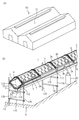
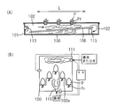
- FIG. 1 is a schematic perspective view which shows the cultivation facility of the plant cultivation apparatus of 1st embodiment of this invention
- B is a perspective view which shows the cultivation box installed in a cultivation facility.
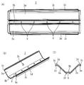
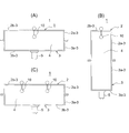
- (A) is a side view showing a state where the cultivation box is held by a gantry
- (B) is an enlarged side view of the cultivation box
- (C) is a cross-sectional view in the length direction of the cultivation box.
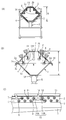
- the upper panel of a cultivation box is shown, (A) is a top view, (B) is a perspective view, and (C) is a sectional view.
- the lower panel of a cultivation box is shown, (A) is a bottom view, (B) is a perspective view, (C) is a sectional view.
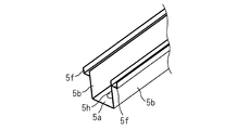
- FIG. 1 It is a perspective view of a gutter.
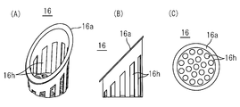
- the pot for cultivation plants is shown, (A) is a perspective view, (B) is a front view, (C) is a top view.
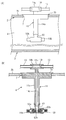
- (A) is the schematic which shows the state which has suspended the nozzle in the cultivation box, (B) is an expanded sectional view of (A).
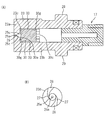
- (A) is a figure which shows the connection part of the nozzle and the joint pipe
- (A) is a cross-sectional view of a nozzle integrated with a strainer, (B) is a cross-sectional view of an essential part of the nozzle.
- FIG. 1 It is drawing which shows the installation of a cultivation facility.
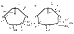
- (A) and (B) are side views of 2nd embodiment of the cultivation box which changed the lower side panel.
- (A) (B) (C) is the schematic of 3rd embodiment of the cultivation box which changed the width
- the nozzle of the pin jet type of a 6th embodiment is shown,
- (A) is a sectional view of a pin jet type nozzle with a strainer
- (B) is a side view of a strainer
- (C) is a partial cross sectional view of a strainer
- (D) is It is an explanatory view showing the state where a straight rod flow collides with a collision pin from an injection hole of a nozzle body.
- (A) (B) is drawing which shows a prior art example.
- (A) to (C) are drawings showing other conventional examples.
- the plant cultivation apparatus opens a worker passage in the cultivation box 1 shown in FIG. 1 (B) inside a cultivation facility 50 consisting of a vinyl house or a glass-lined greenhouse that takes in sunlight. It is juxtaposed in many rows.
- the cultivation boxes 1 are arranged in parallel in eight rows in one house of the cultivation facility. And since it is a tomato etc. which become tall by height at the time of growth in this embodiment, the cultivation box 1 is made into one row in each row.
- two rows of cultivation boxes 1 are provided in each row.
- three or more stages may be used.
- a cultivation box may be installed in a plant factory where the inside of a building is a cultivation facility.
- the cultivation box 1 is provided with a hollow root zone 4 to be a long sealed space where the upper panel 2 and the lower panel 3 are detachably combined and the root Pr of the cultivated plant P is dropped, and the lower part of the lower panel 3
- the gutter 5 is detachably assembled to the.
- Upper panel 2, lower panel 3 and gutter 5 are made of resin or expanded polystyrene. It is lightweight and inexpensive if it is resin or polystyrene foam. The material is not limited as long as it has the required strength, durability, weather resistance, and lightness.
- the cultivation box 1 has a size capable of cultivating the cultivation plants P at regular intervals, and in the present embodiment, the height H of the cultivation box 1 is approximately 30 cm, the width W is 50 cm, and the cultivation box 1 is long. Plural pieces are connected in the longitudinal direction, and the length corresponds to the cultivation facility 50. The height H and the width W may be changed depending on the cultivated plants.
- the upper panel 2 has a substantially mountain shape, and the planting holes 6 are provided on the inclined side walls 2a on both sides extending downward in a two-tiered staggered arrangement.
- a nozzle mounting hole 7 for inserting the nozzle 10 is provided in the top surface 2b sandwiched by the inclined side walls 2a on both sides at intervals in the length direction, and the upper panel 2 is functioned as a planting panel and a nozzle mounting panel.
- a mounting portion 2c protrudes outward, and a downward fitting recess 2d is provided on the lower surface of the mounting portion 2c.
- the nozzle mounting hole 7 provided on the top surface 2b is a rectangular hole whose long side is the long side, and can be smoothly penetrated with the pair of front and rear nozzles 10 (10A, 10B) attached to the lower end of the nutrient solution supply pipe 14 The size is taken.
- One nozzle mounting hole 7 is provided for each of the plurality of planting holes 6 arranged in the length direction. In the present embodiment, one nozzle mounting hole 7 is provided in three planting holes 6 (six in the upper and lower planting holes 6 arranged in a staggered arrangement).
- an inner observation hole 2h is provided in the inclined side wall 2a at a position close to the nozzle mounting hole 7, and a lid 2k for opening and closing the inner observation hole 2h is provided.
- the waste solution port 8 is provided in the bottom wall 3b opposite to the top surface 2b of the upper panel 2 in a substantially symmetrical shape with the upper panel 2 and spaced in the longitudinal direction.
- a receiving plate portion 3c for mounting the placement portion 2c is projected outward on the upper end of the inclined side wall 3a sandwiching the bottom wall 3b, and fitted in the fitting recess 2d of the upper panel 2 on the upper surface of the receiving plate portion 3c. While providing the fitting convex part 3d, the pipe receiving recessed part 3e is provided in the lower surface. Furthermore, the fitting protrusion 3f which attaches the gutter 5 to the external surface full length of the bottom wall 3b is provided.
- a CO 2 introduction hole 3 h is provided in the inclined side wall 3 a of the lower panel 3, and the CO 2 bomb 80 installed outside the cultivation box 2 is in the hollow rhizosphere 4. It is possible to supply CO 2 . Furthermore, the supply time and supply amount of CO 2 from the CO 2 bomb 80 are detected by the CO 2 sensor 72 installed in the rhizosphere part 4 and the detection values of the solar radiation sensor 71 installed in the house, and the growth stage of the plant. It is automatically controlled accordingly.
- the gutter 5 has a bowl shape consisting of a bottom wall 5a and both side walls 5b, and a fitting recess 5f to be fitted with the fitting protrusion 3f is provided at the upper end of both side walls 5b.
- a discharge port 5 h connected to the upper end of the drain pipe 12 is provided.
- the bottom wall 5a of the gutter 5 is provided with a slope to which the waste liquid flows from one end to the other end in the longitudinal direction, and may be an inclined bottom wall. Or you may incline the cultivation box 1 itself currently formed with three members.
- the mounting portion 2c of the upper panel 2 is superimposed on the receiving plate portion 3c of the lower panel 3, and the fitting convex portion 3d is fitted in the fitting concave portion 2d.
- the lower box 3 is assembled, the gutter 5 is assembled to the lower panel 3, and the cultivation box 1 is formed by three members.
- the cultivation box 1 is held by a mount consisting of a commercially available agricultural pipe and a bracket.
- a bracket 11C in which a pipe 11A in the length direction fitted to the pipe receiving recess 3e of the receiving plate portion 3c of the lower panel 3 is attached to the left and right support pipes 11B.
- the left and right support pipes 11B are pierced and erected on the ground G, and the lower end connection pipe 11D and the upper connection pipe 11E supporting the lower surface of the gutter 5 are connected.
- the root Pr of the cultivated plant P is suspended from the hollow root zone 4 of the cultivation box 1 by using the pot 16 shown in FIGS. 6A to 6C in the planting hole 6 of the upper panel 2.
- the pot 16 is made of a resin molded product and is a cylinder with a top opening that is inserted into the planting hole 6, and the upper end is inclined and locked to the inclined peripheral edge so that it can be inserted and locked into the planting hole 6 provided in the inclined side wall 2a.
- the locking piece 16a which protrudes is provided.
- a large number of openings 16 h are provided in the outer peripheral wall and the bottom wall so that the root Pr of the cultivated plant P can be extended to the inside of the rhizosphere part 4 through the openings 16 h.
- a single fluid nozzle for spraying only a nutrient solution is used as a nozzle 10 inserted and installed in the nozzle mounting hole 7 of the upper panel 2.
- the main nutrient solution supply main 13 is inserted and attached to the through hole 14 h of the upper end pipe 14 u of the nutrient solution supply pipe 14.
- the nutrient solution supply pipe 14 is provided with a vertical pipe 14a extending downward from the longitudinal center of the upper end pipe 14u in the horizontal direction, and the through hole of the upper end pipe 14u
- the cut portions of the main nutrient solution supply main 13 are internally fitted and connected to both ends 14 h.
- a lid 70 having a size that closes the rectangular nozzle mounting hole 7 is fixed to the upper outer periphery of the vertical pipe 14a.
- the upper and lower through holes 14c in the vertical pipe 14a communicate with the through holes 14h of the upper end pipe 14u, and the nutrient solution flowing from the main nutrient solution supply main 13 into the through holes 14h of the upper end pipe 14u of the nutrient solution supply pipe 14 is vertical
- the through hole 14c of the pipe 14a is shaped to flow down to the lower end.
- a joint pipe 60 consisting of an inverted T-shaped pipe is connected to the lower end of the vertical pipe 14a, and forward nozzles 10A and backward nozzles are provided at the tips of branch pipes 60a and 60b extending in the front-rear length direction of the lower part of the joint pipe 60 10B is connected by one touch operation only inserting and rotating each.
- the insertion holes 60k are provided on the peripheral walls of the branch pipes 60a and 60b at intervals of 90 degrees, and these insertion holes 60k are locking portions at one end in the rotational direction.
- the reverse T-shaped through hole 60h of the joint pipe 60 communicates with the lower end of the through hole 14c of the vertical pipe 14a of the nutrient solution supply pipe 14, and the nutrient solution flowing from the through hole 14c is sent to the pair of front and rear nozzles 10A and 10B. It is branched and inflowed.
- the vertical pipe 14a of the nutrient solution supply pipe 14 having the pair of front and rear nozzles 10 (10A, 10B) attached to the lower end through the joint pipe 60 can be smoothly passed through the nozzle mounting hole 7 on the top surface 2b of the upper panel 2
- the nozzle mounting hole 7 is closed, and the pair of front and rear nozzles 10 (10A, 10B) is suspended from the hollow root zone 4.
- the nozzle mounting holes 7 are provided at intervals in the length direction, and the nutrient solution supply pipe 14 is disposed at intervals in the length direction in the rhizosphere portion 4 of the cultivation box, and the forward direction of the lower end of each nutrient solution supply pipe 14
- the entire root zone 4 is filled with the mist of the nutrient solution substantially uniformly to make a high humidity environment.
- the forward nozzle 10A and the backward nozzle 10B each have a structure in which a strainer 17 is integrally attached on the upstream side, and flows into the strainer 17 from the main nutrient solution supply main 13 through the nutrient solution supply pipe 14 and the branch pipe of the joint pipe 60.
- the foreign matter of the nutrient solution is removed by a strainer, and it is made to flow into the nozzle 10 and is sprayed.
- the configuration of the strainer 17 will be described later.
- the strainer may be installed in the middle of the nutrient solution supply pipe or between the nutrient solution supply pipe and the joint pipe.
- the nozzles 10 (10A, 10B) are single-fluid nozzles, and spray only nutrient solution in which fertilizer is diluted with water at a required ratio. That is, the two-fluid nozzle requiring the air compressor presented in the conventional example shown in FIG. 16 is not used.
- the nozzle 10 consisting of a single fluid nozzle is an empty conical spray nozzle that sprays nutrient solution as a swirling flow from the tip of the spray hole of the nozzle.
- the average particle size of the spray from the nozzle 10 is 10 to 30 ⁇ m in this embodiment.
- the nozzle 10 is composed of two members, a nozzle body 23 and a closer 30, both of which are resin molded products.
- the nozzle body 23 includes an injection side wall 23a and an outer peripheral wall 23b continuous to the outer periphery of the injection side wall, and the other end facing the injection side wall 23a is an opening.
- the closer 30 is fixedly accommodated in the space 23c surrounded by the injection side wall 23a of the nozzle body 23 and the inner peripheral surface of the outer peripheral wall 23b, and is accommodated in the center of the injection side wall 23a.
- the injection hole 25 is provided with a small diameter portion continuous with the injection port 25a on the injection side, and the small diameter portion is made continuous with a tapered hole 25t in which the inflow end side is spread, and the taper hole is made continuous with the large diameter straight passage 25u. ing.
- the inflow side inner surface of the injection side wall 23a facing the space 23c of the nozzle main body 23 is provided with a circular step portion surrounding the large diameter inlet 25e opened at the center, as shown in FIG.
- a pair of arc-shaped turning grooves 26 are provided at an interval of 180 degrees.
- the inner peripheral end of the turning groove 26 is openly connected to the large diameter inlet 25e at an interval of 180 degrees.
- the turning groove 26 is curved in an arc shape, and the width is gradually narrowed toward the inner peripheral end, and an orifice 27 with a minimum width is provided on the inner peripheral end side.
- the width dimension of the opening of the orifice 27 is the same as the width of the injection port 25 a of the smallest diameter portion of the injection hole 25.
- foreign particles smaller than the injection port are not clogged with the orifice 27 of the turning groove 26, and are discharged to the outside together with the spray of the nutrient solution from the injection port 25a.
- the turning groove 26 has a U-shaped cross section, and the bottom has a rounded shape, and an edge on which the foreign matter is caught is not provided, so that the foreign matter can be easily removed at the time of maintenance.
- the closer 30 has a substantially cylindrical shape and is provided with a liquid inlet 30c at the center of the tip on the inflow side.
- the closer 30 is fixedly fitted in the space 23c of the nozzle main body 23, and the flat end face 30a of the closer 30 is pressed against the step 23d of the nozzle main body 23, and the outer peripheral surface of the closer 30 is The inner circumferential surface of the outer circumferential wall 23b of the second embodiment
- the turning grooves 26, 26 are made a turning passage of a closed cross section.
- Four arc-shaped depressions are provided on the outer peripheral surface 30g of the closer 30 by 90 degrees, and a liquid passage 33 is provided between the outer peripheral surface 30g and the outer peripheral wall 23b of the nozzle body.
- the liquid passage 33 communicates with the liquid inflow portion of the nozzle body 23.
- the outer peripheral wall surrounding the liquid inlet 30 c of the closer 30 is provided with a radial liquid passage communicating with the recess of the liquid inlet 30 c.
- the liquid flowing into the liquid inlet 30c of the closer 30 flows into the liquid inflow portion of the nozzle main body 23 through the liquid passage 33, flows into the injection hole 25 through the turning groove 26 as a swirling flow, and from the injection port 25a at the tip. It is made to be injected outside.
- the nozzle 10 assembled by inserting and fixing the closer 30 to the nozzle body 23 is, as described above, at the tip of the branch pipes 60a and 60b of the joint pipe 60 connected to the lower end of the nutrient solution supply pipe 14 respectively.
- the inflow side is attached by one-touch rotation after being inserted.
- the strainer 17 integrally fixed on the inflow side of the nozzle body 23 is made of a resin material provided with three-dimensionally continuous holes, and has a porosity of 40 to 80%.
- the dimensions of the injection port 25a of the nozzle 10 and the orifice 27 of the swirl groove 26 are larger than the average diameter of the holes of the strainer 17 so that foreign matter clogged by the orifice 27 of the nozzle and the injection port 25a can be captured by the strainer 17 in advance. ing.
- the nutrient solution Q supplied from the main nutrient solution supply main pipe 13 is introduced into the strainer 17 integral with the nozzle 10 through the nutrient solution supply pipe 14 and the branch pipes 60a and 60b of the joint pipe 60. Contaminating foreign matter is captured.
- the nutrient solution passing through the strainer 17 flows into the closer 30 in the nozzle 10 and flows into the swirl groove 26 through the liquid passage 33.
- the fluid cross-sectional area is gradually decreased toward the orifice 27, so the liquid pressure is increased, and flows into the injection hole 25 while flowing and flows from the injection port 25a of the nozzle body 23. While being injected, it scatters to the outside.
- the flight distance of the spray injected to the outside becomes longer. And since it distribute
- the average particle diameter is 10 to 100 ⁇ m, preferably 10 to 50 ⁇ m or less, more preferably 10 to 30 ⁇ m. Can be sprayed.
- a plurality of main nutrient solution supply mains 13 are provided to the top surface 2b of the upper panel 2 of each cultivation box 1 (this embodiment).
- the four pipes are connected in series to the supply pipe 40, and the supply pipe 40 is connected collectively to the fertilization tank 42 storing the nutrient solution to be sprayed via the supply main pipe 41.
- a water level sensor 58, an agitator 59, and an EC / PH sensor 69 are installed in the fertilization tank 42.
- An electric on-off valve 44 controlled by a control panel 43 is interposed in each supply pipe 40, and a pump 45 controlled by the control panel 43 is interposed in the supply main pipe 41.
- the fertilization tank 42 is connected to the water supply pipe 52, and is connected to the concentrated solution fertilization tank 46 and the acid alkali tank 47 via a pipe to provide a liquid fertilizer mixing unit 65. Also, the fertilization tank 42 is connected to the circulating chiller device 48 via the circulation pipe 49 to prevent overheating of the liquid fertilizer stored in the fertilization tank 42.
- the drain pipe 12 connected to the gutter 5 is connected to the return tank 55 via the drain pipe 54, the waste liquid collected in the return tank 55 is connected to the purifier 56 via the circulation pipe 57, It is returned to the return tank 55.
- the purification device 56 the waste liquid is disinfected using UV, ozone, photocatalyst, etc. and regenerated as a nutrient solution.
- a pumping pump 66 is installed in the tank, and the pumped waste fluid is filtered through the automatic cleaning filter 62 through the pipe 61, and then applied to the fertilization tank 42. I'm back. As described above, the waste fluid purified and filtered is supplied to the fertilization tank 42 to reuse the nutrient solution without waste.
- the control panel 43 is electrically connected to the electric on-off valve 44, the water level sensor 58 installed in the fertilization tank 42, the stirrer 59, and the EC / PH sensor 69, and also the electromagnetic on-off valve installed on various pipes and pressure sensor
- the flow rate sensor is connected to the pump 66 in the return tank 55 to output a drive signal and to receive detection values from the various sensors.
- a controller for providing a solar radiation sensor 71 shown in FIG. 1A in the house of the cultivation facility 50 and inputting detection values of the solar radiation sensor 71 and a CO 2 sensor 72 installed in the root zone of the cultivation box 1 70 is provided.
- the controller 70 also receives detection values of the various sensors from the control panel 43.
- the liquid fertilizer tank 46 and the acid / alkali tank 47 transmit a command to control the supply amounts of the concentrate, acid, and alkali components supplied to the fertilization tank 42.
- moves at the time of a power failure is provided.
- the controller 70 automatically controls the CO 2 concentration in the rhizosphere of the cultivation box 1 and the spraying cycle of the nutrient solution from the fertilization tank 42 according to the growth stage of the plant and the detection value of the solar radiation sensor 71 by the controller 70 doing.
- the growth stages of the plants are divided into, for example, early, middle and final stages.
- the root zone 4 of the cultivation plant P is fed with nutrient solution from each nozzle 10 (10A, 10B) in each cultivation box 1 through the joint pipe 60 provided with the nutrient solution supply pipe 14 and the branch pipe.
- Spray towards the high humidity nutrient solution environment Since the spray has an average particle diameter of 10 to 50 ⁇ m (10 to 30 ⁇ m in the present embodiment), it is possible to suppress aggregation and falling as water droplets, and suspend in the air in the cultivation box 1. Since Pr easily adsorbs a nutrient solution, the absorption efficiency of nutrient solution can be enhanced. And the amount of nutrient solution spray from the nozzle is a spray amount such that the root zone of the cultivation box 1 becomes high humidity.
- the nozzle 10 is suspended from the top surface 2 b of the upper end of the upper panel 2 into the hollow root zone 4, and the planting holes 6 are vertically two stages in the inclined side walls 2 a and 2 a on both sides.
- the root Pr of the cultivated plant P is placed in the pot 16 and suspended in the hollow root zone 4. Therefore, the planting plants P can be fixed at a high density while reducing the size of the cultivation box 1, and the number of nozzles 10 for spraying the nutrient solution onto the root zone of these cultivation plants can be reduced.
- attachment of the nozzle 10 to the upper panel 2 can be easily installed simply by piping the main nutrient solution supply main 13 on the top surface 2 b and positioning and inserting the nozzle 10 in the nozzle attachment hole 7
- the nozzle mounting hole 7 can be closed by the lid 70 fixed to the nutrient solution supply pipe 14 to which the nozzle 10 is attached.
- the nozzle 10 can be taken out only by pulling up the nutrient solution supply pipe 14 upward.
- the internal observation hole 2 h is provided in the vicinity of the nozzle attachment portion, the inside of the hollow root zone 4 can be easily observed by removing the lid 2 k.
- the CO 2 is supplied from the CO 2 cylinder 80 into the cultivation box 1, the growth of cultivated plants can be promoted. Also, the control panel 43 and the controller 70 can be provided, and the EC and PH of fertilization can be properly and automatically blended corresponding to the growth stage of the cultivated plant. Furthermore, it is possible to notify the operator of an abnormality in the electrical system, thereby improving the work efficiency and reducing the work load.
- the cultivation box 1 can easily assemble the upper panel 2, the lower panel 3, and the gutter 5 in the cultivation facility 50.
- a plurality of these upper and lower panels 2 and 3 can be stacked and transported to a cultivation facility, which is excellent in transportability and can reduce initial cost.
- the nutrient solution to be sprayed prevents overheating of the fertilization tank 42 using the chiller device 48, the temperature in the cultivation box 1 is increased by spraying, and the root Pr can be prevented from being killed.
- 11A and 11B show a second embodiment in which the form of the cultivation box is changed.
- the inclined side walls 3a on both sides of the lower panel 3 may be formed into a stepped shape of an upper portion 3a1 having a steep inclination angle and a lower side 3a2 of the bottom side having a gentle inclination angle.
- the lower volume of the hollow root zone portion 4 surrounded by the upper panel 2 and the lower panel 3 can be increased, and the root Pr of the cultivated plant P grows even if the root grows. Intertwining can be suppressed, and the flight distance of the spray from the nozzle 10 can be secured.
- the 3rd embodiment which changed the form of the cultivation box to FIG. 12 (A) (B) (C) is shown.
- the side walls 2a-3 on both sides of the upper panel 2 and the side walls 3a-3 on both sides of the lower panel 3 are vertical, and the top surface 2b-3 of the upper panel 2 and the lower panel 3 are Bottom wall 3b-3 is horizontal.
- the third embodiment A of FIG. 12A is wide and shallow, and the volume of the hollow root zone 4 is expanded in the width direction.
- a nozzle mounting hole is provided at the center in the width direction of the top surface 2 b-3 of the upper panel 2, and the nozzle 10 is inserted and suspended from the root zone 4.
- Planting holes (not shown) are provided at positions sandwiching the nozzle mounting holes into which the nozzles 10 are inserted, and pots for filling roots of cultivated plants are attached to these planting holes as in the first embodiment.
- This third embodiment A is suitably used in the case where the roots of cultivated plants are laterally spread.
- the width is deep and deep, the volume of the hollow root zone 4 is expanded in the depth direction, and the root of the cultivated plant is preferably used in the case of longitudinal.
- the third embodiment C of FIG. 12 (C) is the same wide and shallow as the third embodiment A, and the volume of the hollow root zone 4 is expanded in the width direction.
- two nozzle mounting holes are provided at intervals in the width direction of the top surface 2 b-3 of the upper panel 2, and the nozzles 10 are respectively inserted and suspended in the root zone 4.
- Planting holes are provided at positions sandwiching the nozzle mounting holes into which the respective nozzles 10 are inserted, and pots for filling roots of cultivated plants are attached to these planting holes in the same manner as in the first embodiment. .
- cultivated plants can be cultivated in two rows in the width direction.
- FIG. 13 shows a fourth embodiment in which the form of the cultivation box is changed.
- the hollow root zone 4 is formed by the upper panel 2 and the lower panel 3.
- the slopes on both sides of the upper panel 2 and the lower panel 3 An intermediate panel 85 made of a rectangular flat plate is interposed between the side walls 2a and 3a to expand the volume of the rhizosphere portion 4.
- the upper end surface 85a of the middle panel 85 is brought into contact with the mounting portion 2c protruding outward from the lower end of the inclined side wall 2a of the upper panel 2, and the fitting recess 2d provided on the lower surface of the mounting portion 2c.
- the fitting convex part 8d to which it fits is protruded from the center of the upper end surface 85a.
- the lower end surface 85b of the middle panel 85 is brought into contact with the receiving plate portion 3c protruding outward from the upper end of the inclined side wall 3a of the lower panel 3, and the fitting convex provided on the upper surface of the receiving plate portion 3c.
- a fitting recess 8e for fitting the portion 3d is provided to project from the center of the lower end surface 85b.
- the upper panel 2 and the lower panel 3 can use the same panels as in the case of direct connection without the intermediate panel 85, and only by using the left and right intermediate panels 85, the root of the plant to be cultivated When the growth is large, the volume of the root zone 4 can be expanded to cope with it.
- the volume of the root zone according to the growth amount of the root of the plant to be grown Can be adapted to cultivated plants.
- FIG. 14 shows a fifth embodiment in which the arrangement of the cultivation box 1 in the house of the cultivation facility is changed.
- the cultivation box 1 is one-tiered, but in the fifth embodiment, the cultivation box 1 is attached to the support pipe 11B in upper and lower two tiers.
- the cultivation box 1 is in one row in order to use a tall tomato or the like as the cultivation plant P, but for low-back plants such as lettuce and strawberries, as shown in the fifth embodiment,
- the upper cultivation box 1-U may be attached to the top of the cultivation box 1-D with a required height space being left. With this configuration, productivity can be enhanced.
- the planting holes are not limited to the upper and lower two stages of the staggered arrangement, and may be one stage or three or more stages.
- the shape of the upper panel is not limited to a mountain shape, and a horizontal upper surface may be provided, a nozzle mounting hole may be provided at the center of the upper surface, and a planting hole may be provided on both sides.
- the upper surface may be arranged along the outer wall of the cultivation facility as a one-flow triangle.
- FIG. 15 shows a sixth embodiment using a pin jet type nozzle of one fluid nozzle as a spray nozzle.
- a pin jet type with a strainer instead of the swirl type empty conical nozzle 10 of the first embodiment at the front and rear ends of the joint pipe 60 at the lower end of the nutrient solution supply pipe 14 suspended in the rhizosphere part 4 of the cultivation box 1
- the nozzle 10-P is used.
- the pin jet type nozzle 10-P is provided with an injection hole consisting of a straight hole for injecting a straight advancing rod flow at the center of the injection side closing wall of the nozzle body, and from the outer surface of the injection side closing wall of the nozzle body.
- a pin for collision with which the straight advancing rod flow collides is protruded at a position facing the injection hole, and the straight advancing rod flow jetted from the injection hole is made to collide with the collision pin to achieve atomization of the spray.
- the pin jet type nozzle 10-P has a strainer 17 made of a resin porous material attached thereto.
- the nozzle 10-P has a J-shaped collision frame 93 protruding from the outer surface of a jet side wall 92a formed by a closed end wall of a cylindrical nozzle body 92 molded by metal injection.
- the collision frame 93 includes a vertical frame 93a protruding from the tip outer surface of the injection side wall 92a, and a horizontal frame 93b protruding from the tip of the vertical frame 93a across the central axis, and the tip side of the crossing frame 93b
- the pin hole 93c is provided in the central axis of the.
- a ceramic collision pin 94 is inserted into the pin hole 93c and protrudes toward the jet side wall 92a of the nozzle body, and the back surface is fixed with an adhesive 98 in the pin hole 93c.
- the projecting portion of the collision pin 94 is a conical shape that narrows toward the tip, and is provided with a small diameter collision surface 94a.
- the injection hole 95 consisting of a straight hole is provided on the central axis of the injection side wall 92a at one end of the nozzle main body 92, and the straight passage 96 having a circular cross section and a constant inner diameter surrounded by the flat inner surface and outer peripheral wall of the injection side wall 92a. Is equipped.
- the injection hole 95 is in communication with the straight passage 96, and injects the nutrient solution as a straight rod flow from the straight passage 96 through the injection hole 95.
- the diameter of the collision surface 94 a of the collision pin 94 is in the range of 100% to 115% of the diameter of the opposing injection hole 95.
- the spray pressure is 0.5 to 2.0 MPa
- the spray flow rate is 1 to 5 L / hr
- the average particle diameter of the nutrient solution to be sprayed is 10 ⁇ m to 100 ⁇ m, preferably 10 ⁇ m to 50 ⁇ m, more preferably 10 ⁇ m It is about 30 ⁇ m.
- the nozzle body 92 has a locking piece 99 projecting at an interval of 90 degrees so that it can be connected to the branch pipe of the joint pipe by one-touch operation as shown in FIG.
- connection can be made by simply rotating the insertion holes 60k provided at 90 ° intervals in the branch pipe.
- the rear end of the nozzle body 92 is open, and the front portion 17 a of the strainer 17 is internally fitted.
- the strainer 17 is made of a resin material provided with three-dimensionally continuous holes 17c as shown in FIG. 15C, and the porosity is set to 40 to 80%.
- the strainer 17 is continuous with a front portion 17a and a rear portion 17b, and has a liquid passage 17h consisting of a central hole from the front end of the front portion 17a to the middle portion of the rear portion.
- the liquid passage 17 h is open to the straight passage 96, and is made to flow from the straight passage 96 to the injection hole 95.
- the outer peripheral surface of the rear portion of the strainer 17 has four petal portions 17c protruding to form a petal shape, and the surface area is increased to increase the liquid absorption amount of the strainer 17.
- the nozzle 10-P attached with the strainer 17 is a plant that cultivates the nutrient solution from the front and rear direction at both ends of the joint pipe at the lower end of the nutrient solution supply pipe suspended to the rhizosphere part 4 of the cultivation box 1 It is attached to spray towards the root. It flows into the injection hole 95 through the straight flow passage 96 of the nozzle main body 92 through the strainer 17 and is injected from the injection hole 95 formed as a fine hole as the straight movement rod flow Qs as shown in FIG. Collide with the collision surface 94 a at the tip of the collision pin 94.
- the diameter of the injection hole 95 is small, the pressure of nutrient solution passing through the injection hole 95 is increased, the injection pressure is increased, the straight rod flow Qs is injected, and the collision surface is collided.
- the droplets are micronized and fly outward.
- the straight moving rod flow having a high pressure to collide with the collision pin it is possible to spray with an average particle diameter of 10 to 50 ⁇ m or less.
- there is no swirl groove in the empty conical nozzle which sprays swirl flow and it is a straight injection hole it is excellent at the point which is hard to be clogged.
- the collision pin is made of ceramic, it is possible to prevent the wear due to the collision of the straight advancing rod flow which is high in pressure.
- FIG. 16 shows a seventh embodiment, and uses a pin jet type single fluid nozzle 10-PP of another embodiment.
- the pin jet type single fluid nozzle 10-PP is formed by insert molding a tip member 86 on the injection side obtained by integrally molding injection holes 86h consisting of straight holes and collision pins 86p by a ceramic into a nozzle main body 87 consisting of fluorocarbon resin. doing.
- the tip member 86 on the injection side projects a U-shaped collision frame 86b from both sides of the injection side wall 86a attached to the injection side opening of the nozzle main body 87, and the tips of both side vertical frames 86b1 of the collision frame 86b
- the collision pin 86p is provided on the central axis of the horizontal frame 86b2 connecting the two.
- An injection hole 86h is provided at the center of the injection side wall 86a, and the injection hole 86h and the collision pin 86p are set in the same relationship as the nozzle 10-P of the fifth embodiment.
- the nozzle main body 87 whose injection side opening is closed by the tip member 86 has a linear flow passage 87b surrounded by a cylindrical outer peripheral wall 87a and an injection side wall 86a, and the linear flow passage 87b is communicated with the injection hole 86h There is.
- Locking pieces 87k are provided on the outer peripheral wall of the outer peripheral wall 87a at an interval of 90 degrees so that they can be connected to the branch pipe of the joint pipe by one-touch operation in the same manner as the nozzle shown in FIG. It is made to be able to connect only by rotating to the insertion hole provided at 90 degree intervals in the branch pipe.
- the strainer 17 is connected to the nozzle body 87 as in the above embodiment.
- the nozzle according to the seventh embodiment is used in the same manner as the nozzle according to the sixth embodiment, and straight rod flow is injected from the injection hole 86 h having a narrow hole, and collides with the collision surface of the tip of the collision pin 86 p at the opposing position. , All droplets are micronized and splash outward. As described above, by causing the straight moving rod flow having a high pressure to collide with the collision pin, it is possible to spray with an average particle diameter of 10 to 50 ⁇ m or less.
Landscapes
- Life Sciences & Earth Sciences (AREA)
- Environmental Sciences (AREA)
- Chemical & Material Sciences (AREA)
- Engineering & Computer Science (AREA)
- Water Supply & Treatment (AREA)
- Chemical Kinetics & Catalysis (AREA)
- Hydrology & Water Resources (AREA)
- Environmental & Geological Engineering (AREA)
- Organic Chemistry (AREA)
- Forests & Forestry (AREA)
- Ecology (AREA)
- Botany (AREA)
- Biodiversity & Conservation Biology (AREA)
- Health & Medical Sciences (AREA)
- Toxicology (AREA)
- Hydroponics (AREA)
- Cultivation Of Plants (AREA)
Abstract
Description
また、前記特許文献1、2では、長さ方向の一端に設置した1個のノズルからの噴霧を他端に設置したファンで循環させるため、噴霧の飛距離を伸ばす必要がある。そのため、該ノズルとして二流体ノズルを用いることになる。しかしながら、二流体ノズルを用いると、圧力空気を供給するエアコンプレッサを必要とし、設備コストおよびランニングコストがかかる問題がある。一方、特許文献3では、各栽培植物の根に向かって養液を噴霧するため噴霧の飛距離を伸ばす必要は無く、一流体ノズルを用いることができ、設備コストおよびランニングコストの低減を図ることができる。
前記栽培ボックスを上側パネルと下側パネルを着脱自在に組み合わせて設けると共に、該下側パネルの廃液口を設けた底壁の下部に長さ方向全長に亙って樋形状のガターを着脱自在に取り付けており、
前記上側パネルは長さ方向に間隔をあけてノズル装着穴を備え、各ノズル装着穴に養液噴霧用のノズルを差し込んで前記根圏部に吊り下げると共に、該上側パネルは栽培植物の植付穴を備え、該植付穴に栽培植物の根部を差し込んで前記根圏部に吊り下げて前記ノズルから養液を噴霧する構成としていることを特徴とする植物栽培装置を提供している。
搬送時には複数の下側パネルを積み重ね、複数の上側パネルも積み重ねて輸送でき、梱包容量が小さくなり、輸送性に優れる。かつ、栽培ボックスは下側パネルに上側パネルを被せて搭載するだけで簡単に組み立てられ、栽培ボックスを小型化できる。
前記のように、栽培ボックスを小型化し根圏部の容積を小さく出来るため、少ない噴量で小さい中空の根圏部内を効率よく霧を充満させて、高湿度の養液環境にでき、効率良く栽培植物の根に養液を吸収させることができる。このように、供給する養液量を低減でき、その結果、余剰養液を減少することができる。
かつ、前記下側パネルおよび前記上側パネルの幅および高さを変えて、前記栽培ボックスを幅広、幅狭、浅底、深底のいずれかの形状とし、
さらに、該上側パネルの両側の傾斜側壁の間の頂面に前記ノズル装着穴を設けると共に、前記傾斜側壁に千鳥配置で前記植付穴を設ける構成とすることが好ましい。
かつ、前記下側パネルおよび前記上側パネルの幅および高さを変えて、前記栽培ボックスを幅広、幅狭、浅底、深底のいずれかの形状とし、
さらに、幅狭の前記上側パネルの頂面に1つの前記ノズル装着穴を設け、又は幅広の前記上側パネルの頂面に複数の前記ノズル装着穴を間隔をあけて設け、
かつ、該ノズル装着穴を挟む位置に前記植付穴を設けてもよい。
なお、上側パネルは略山形状でなく、栽培室の壁面に沿って設置する栽培ボックスでは、一側壁を傾斜側壁とし、他側壁は植付穴が無い垂直壁とした直角三角形状としてもよい。その場合、該上側パネルと組み合わせる下側パネルも同様な直角三角形状となる。
前記上側パネルの幅方向両側の側壁の下端に外側に向けて突設した載置部を設け、該載置部に被嵌合部を設け、
前記上側パネルの前記載置部を前記下側パネルの前記受板部に載せて前記被嵌合部と前記嵌合部を嵌合し、あるいは前記上側パネルと下側パネルの両側の側壁の間に介在させて前記根圏部の容積を拡大する中間パネルを設け、該中間パネルの上端と下端に外側に突設した連結板部を前記載置部と受板部にそれぞれ当接させて連結している。
前記中間パネルの上下端の連結板部には、上側パネルの載置部に設けた被嵌合部と嵌合する嵌合部、下側パネルの受板部に設けた嵌合部と嵌合する被嵌合部を設けている。
前記嵌合部は嵌合凸部、被嵌合部は嵌合凹部とし、凹凸嵌合することが好ましい。
さらに、上側パネルと下側パネルの間に前記中間パネルを介在させてもよい。このように中間パネルを用いると上側パネルと下側パネルは変えることなく、中間パネルを介在させて取り付け、かつ、該中間パネルの高さを変えることで、栽培する植物の根の成長量に応じた根圏部の容積として、栽培植物に対応することができる。
前記上側パネルに植え付ける栽培植物が葉物野菜等で低背であれば、前記栽培ボックスを上下複数段で前記左右両側の支柱パイプで支持して取り付けると、高密度で栽培することができる。トマト等の背の高い作物の場合は栽培ボックスを一段としている。
前記長さ方向に並設させる複数本の栽培植物の間に前記ノズルを配置し、これらノズルを主養液供給本管に間隔をあけて取り付け、該主養液供給本管を上側パネルの上面に搭載して配管し、前記各ノズルを前記ノズル装着穴に差し込むだけで取り付けられるものとしている。
このように、前後一対のノズルを前後長さ方向の先端に取り付けた養液供給管を前記ノズル装着穴に差し込むだけで、上側パネルと下側パネルで囲まれた根圏部にノズルを取り付けられ、組立作業性を高めることができる。
具体的には、長さ方向に並設させる栽培植物の3~10本に1本の割合で前後一対のノズルを取り付けた1本の養液供給管を配置している。尚、ノズルは前後一対に限定されず、片側だけとしてもよい。
該垂直管の上端に前記蓋板を取り付けると共に、下端に前記逆T形状の継ぎ手管を連結し、
該継ぎ手管の下部の前後長さ方向に延在する分岐管の先端に前記前向きノズルと後向きノズルとを挿入して回転するだけのワンタッチ操作で連結できるようにしている。
前記前向きノズルと後向きノズルは、それぞれノズルの上流側にストレーナを一体的に取り付けた構造とし、主養液供給本管から養液供給管、継ぎ手管の分岐管を通してストレーナに流入する養液の異物をストレーナで除去した後、ノズルに流入させて噴霧している。 前記養液供給管を栽培ボックスの根圏部に長さ方向に間隔をあけて配置し、各養液供給管の下端で前向きノズルから前向きに養液を噴霧し、後向きノズルから後向きに養液を噴霧して、根圏部の全体に略均等に養液の霧を充満させている。
前記空円錐形ノズルは、例えば、ノズル本体とクローザーを備え、前記ノズル本体は中央に噴射穴が貫通した噴射側壁と外周壁を備え、該ノズル本体の噴射側壁と外周壁の内周面に囲まれた空間に前記クローザーが収容され、前記ノズル本体の噴射穴の大径流入口を前記噴射側壁の流入側内面の中央部分または前記クローザーの噴射側端面の中央部分に位置し、該大径流入口を囲む外周段部に設けられる円弧状の旋回溝の内周端が前記大径流入口に開口すると共に、前記旋回溝の外周端を前記クローザーの外周に設けられる液通路に開口させて前記旋回溝を流れる旋回流が前記噴射穴より噴霧されるものとし、かつ、前記旋回溝の内周端にオリフィスを備え、該オリフィスの最小部分の寸法は前記噴射穴の最小径部分の寸法と同等とされるノズルを用いることが好ましい。
該ピンジェット形ノズルでは噴射穴から噴射する直進棒流を前記衝突ピンに衝突させて、噴霧の微細化を図っている。
前記衝突ピンはノズル本体の噴射側閉鎖壁から突出するJ字状あるいはU字状の衝突枠を突設し、該衝突枠に設ける前記衝突用ピンはアルミナ等のセラミックで形成し、衝突する直進棒流による摩損を低減していることが好ましい。
さらに、栽培ボックスの中空の根圏部内で下方に落下する余剰養液(廃液)の液滴は下側パネルの底部に集まり、側壁に付着する液滴も側壁から底部へ自重落下させ、下側パネルの底壁に設けた廃液用開口から下方のガターに流下させているため、根圏部の底部に廃液を溜めず、成長した栽培植物の根が廃液に浸って根腐れするのを防止できる。
図1乃至図10に第一実施形態を示す。
植物栽培装置は図1(A)に示すように、太陽光を取り入れるビニルハウスまたはガラス張りの温室等からなる栽培施設50の内部に図1(B)に示す栽培ボックス1を作業員通路をあけて多数列で並設している。なお、本実施形態では栽培施設の1つのハウス内に8列で栽培ボックス1を並設している。かつ、本実施形態では栽培植物Pが成長時には高背となるトマト等であるため、各列に栽培ボックス1は一段としている。なお、低背のレタス等の葉物野菜では図13に示すように、各列に栽培ボックス1を上下2段としている。更に3段以上としてもよい。また、太陽光を取り入れる温室等に代えて建造物の内部を栽培施設とする植物工場内に栽培ボックスを設置してもよい。
上側パネル2、下側パネル3およびガター5は樹脂または発泡スチロールからなる。樹脂または発泡スチロールとすると軽量かつ安価となる。所要の強度、耐久性、耐候性、軽量性があれば素材は限定されない。該栽培ボックス1は栽培植物Pを一定間隔をあけて栽培できる大きさとしており、本実施形態では栽培ボックス1の高さHは略30センチ、幅Wは50センチとし、該栽培ボックス1を長さ方向に複数連結して、栽培施設50に応じた長さとしている。なお、栽培植物により高さH、幅Wを変えてもよい。
さらに、ノズル装着穴7に近接した位置の傾斜側壁2aに、内部観察穴2hを設け、該内部観察穴2hを開閉する蓋2kを設けている。
なお、図2(C)に示すように、ガター5の底壁5aは長さ方向の一端から他端にかけて廃液が流れ落ちるスロープを設け、傾斜底壁としてもよい。あるいは、3部材で形成している栽培ボックス1そのものを傾斜させてもよい。
ポット16は樹脂成形品からなり、植付穴6に挿入する上面開口の円筒で、傾斜側壁2aに設けた植付穴6に挿入係止できるように、上端は傾斜させると共に傾斜周縁に係止する係止片16aを突設している。かつ、外周壁および底壁に多数の開口16hを設け、栽培植物Pの根Prが開口16hを通して根圏部4の内部に伸びられるようにしている。
垂直管14aの上部外周に、長方形状のノズル装着穴7を閉鎖する大きさとした蓋材70を固着している。垂直管14a内の上下の貫通穴14cは上端管14uの貫通穴14hに連通し、主養液供給本管13から養液供給管14の上端管14uの貫通穴14hに流入した養液が垂直管14aの貫通穴14cを下端まで流下する形状としている。
分岐管60aと60bの周壁に図8(A)(B)(C)に示すように90度間隔をあけて差込穴60kを設け、これら差込穴60kは回転方向の一端に係止部60iを備え、後述するノズル10(10A、10B)の90度間隔をあけて設けた係止片29を差込穴60kに挿入した後、回転させると、係止片29が係止部60iと係止して連結できる形状としている。
該継ぎ手管60の逆T字状の貫通穴60hは養液供給管14の垂直管14aの貫通穴14cの下端と連通し、貫通穴14cから流入する養液を前後一対のノズル10A、10Bに分岐して流入させている。
ノズル装着穴7を長さ方向に間隔をあけて設け、養液供給管14を栽培ボックスの根圏部4に長さ方向に間隔をあけて配置し、各養液供給管14の下端の前向きノズル10Aから前向きに養液を噴霧し、後向きノズル10Bから後向きに養液を噴霧することで、根圏部4の全体に略均等に養液の霧を充満させて高湿度環境としている。
ストレーナーは養液供給管の途中もしくは養液供給管と継ぎ手管の間に取り付けてもよい。
一流体ノズルからなるノズル10は、ノズルの噴射穴の先端から旋回流として養液を噴霧する空円錐噴霧ノズルとしている。該ノズル10からの噴霧の平均粒子径は本実施形態では10~30μmとしている。
クローザー30の外周面30gに90度間隔をあけて4つの円弧状の窪みを設け、ノズル本体の外周壁23bとの間に液通路33を設けている。該液通路33はノズル本体23の液流入部に連通させている。
クローザー30の液流入口30cを囲む外周壁には、液流入口30cの窪みと連通する径方向の液通路を設けている。これにより、クローザー30の液流入口30cに流入する液が液通路33を通してノズル本体23の液流入部に流入し、旋回溝26を通して噴射穴25に旋回流として流入し、先端の噴射口25aから外部に噴射されるようにしている。
ノズル本体23の流入側に一体的に内嵌固定するストレーナ17は三次元状に連続する空孔を備えた樹脂材からなり、空孔率は40~80%としている。ノズル10の噴射口25aおよび旋回溝26のオリフィス27の寸法は、ストレーナ17の空孔の平均径より大きくして、ノズルのオリフィス27および噴射口25aで詰まる異物をストレーナ17で予め捕捉できるようにしている。
旋回溝26を流通する過程で、オリフィス27に向けて流路断面積を漸次減少しているため液体圧が高められ、噴射穴25へ旋回しながら流れ込み、ノズル本体23の噴射口25aより旋回しながら噴射され、外部へ飛散する。旋回溝26のオリフィス27および噴射穴25の最小径部分で噴射圧が高められることより、外部に噴射される噴霧の飛距離は長くなる。かつ、旋回溝26で旋回された状態で噴射穴25を旋回しながら流通するため、液滴同士が衝突して微粒化される。このように、微粒化機能が優れているため、噴霧圧力を0.5MPa~2MPaの低圧としても、平均粒子径が10~100μm、好ましくは10~50μm以下、更に好ましくは10~30μmのセミドライフォグを噴霧できる。
さらに、停電時に作動する発電機または充電用太陽光発電パネルから給電されるバッテリーを備えている。
かつ、ノズル取付部分に近接して内部観察穴2hを設けているため、蓋2kを外して簡単に中空の根圏部4内を観察することができる。
また、噴霧する養液は施肥タンク42をチラー装置48を用いて過熱防止を図っているため、噴霧により栽培ボックス1内の温度が上昇し、根Prが死滅するのを防止できる。
図示のように、下側パネル3の両側の傾斜側壁3aを傾斜角度を急激にした上側部3a1と、傾斜角度をゆるくした底側の下側部3a2の段状としてもよい。変形例(A)(B)の形状とすると、上側パネル2と下側パネル3で囲まれる中空の根圏部4の下部容積を増大でき、栽培植物Pの根Prが成長しても、根同士が絡み合うのを抑制でき、ノズル10からの噴霧の飛距離を確保できる。
第三実施形態の栽培ボックス1は上側パネル2の両側の側壁2aー3及び下側パネル3の両側の側壁3a-3は垂直とし、上側パネル2の頂面2bー3および下側パネル3の底壁3b-3は水平としている。
この第三実施形態Aは、栽培植物の根が横広がりの場合に好適に用いられる。
図12(C)の第三実施形態Cは第三実施形態Aと同じ幅広で浅底とし、中空の根圏部4の容積を幅方向に広げている。該第三実施形態Cでは上側パネル2の頂面2bー3の幅方向に間隔をあけてノズル装着穴を2個設け、それぞれノズル10を差し込んで根圏部4に吊り下げている。前記各ノズル10を差し込むノズル装着穴を挟む位置に植付穴(図示せず)を設け、これら植付穴に前記第一実施形態と同様に栽培植物の根部を充填するポットを装着している。該第三実施形態Cの栽培ボックス内には栽培植物を幅方向で2列に並べて栽培することができる。なお、栽培ボックスの幅をさらに広げて、3列、4列でノズルを吊り下げ、栽培植物を対向させて3列、4列で栽培することも可能である。
前記第一~第三実施形態では上側パネル2と下側パネル3とで中空の根圏部4を形成しているが、第四実施形態では、上側パネル2と下側パネル3の両側の傾斜側壁2a、3aの間に長方形状の平板からなる中間パネル85を介在させて根圏部4の容積を拡大している。詳しくは、中間パネル85の上端面85aは上側パネル2の傾斜側壁2aの下端から外向きに突設した載置部2cと当接させ、該載置部2cの下面に設けた嵌合凹部2dを嵌合する嵌合凸部8dを上端面85aの中央から突設している。
同様に、中間パネル85の下端面85bは下側パネル3の傾斜側壁3aの上端から外向きに突設した受板部3cと当接させ、該受板部3cの上面に設けた嵌合凸部3dを嵌合する嵌合凹部8eを下端面85bの中央から突設している。
このように、上側パネルと下側パネルは変えることなく、中間パネル85を取り付け、かつ、該中間パネルの高さを変えることで、栽培する植物の根の成長量に応じた根圏部の容積を変えて、栽培植物に対応することができる。
前記第一実施形態では背の高いトマト等を栽培植物Pとするため、栽培ボックス1は一段としているが、レタス、イチゴ等の低背植物では、該第五実施形態で示すように、下段の栽培ボックス1-Dの上部に上段の栽培ボックス1-Uを所要の高さ空間を空けて取り付けてもよい。該構成とすると、生産性を高めることができる。
栽培ボックス1の根圏部4に吊り下げる養液供給管14の下端の継ぎ手管60の前後両端に、第一実施形態の旋回型の空円錐ノズル10に代えて、ストレーナ付きのピンジェット型のノズル10-Pを用いている。該ピンジェット型のノズル10-Pはノズル本体の噴射側閉鎖壁の中心に直進棒流を噴射する直線穴からなる噴射穴を備えていると共に、該ノズル本体の噴射側閉鎖壁の外面から前記噴射穴と対向する位置に直進棒流が衝突する衝突用ピンを突設し、噴射穴から噴射する直進棒流を前記衝突ピンに衝突させて、噴霧の微細化を図るものである。
該ノズル10-Pでは、噴霧圧を0.5~2.0MPa、噴霧流量を1~5L/hr、噴霧する養液の平均粒子径を10μm~100μm、好ましくは10μm~50μm、さらに好ましくは10μm~30μmとしている。
かつ、旋回流を噴霧する空円錐形ノズルにある旋回溝が無く、直線の噴射穴なので目詰まりしにくい点で優れている。また、衝突ピンをセラミック製としているので、高圧とした直進棒流の衝突による摩耗を防止することができる。
該ピンジェット型一流体ノズル10-PPは、直線穴からなる噴射穴86hと衝突ピン86pをセラミックで一体成形した噴射側のチップ部材86をフッ素系樹脂からなるノズル本体87にインサートモールドして形成している。
2 上側パネル
2a 傾斜側壁
2b 頂面
3 下側パネル
3a 傾斜側壁
3b 底壁
4 中空の根圏部
5 ガター
6 植付穴
7 ノズル装着穴
8 廃液口
10(10A、10B、10-P、10-PP) ノズル
13 主養液供給本管
14 養液供給管
16 ポット
80 CO2ボンベ
85 中間パネル
P 栽培植物
Pr 根
Claims (13)
- 栽培植物の根を下垂させる中空の根圏部を有する栽培ボックスを備え、前記根圏部に養液を霧状にして噴霧する植物栽培装置において、
前記栽培ボックスを上側パネルと下側パネルを着脱自在に組み合わせて設けると共に、該下側パネルの廃液口を設けた底壁の下部に長さ方向全長に亙って樋形状のガターを着脱自在に取り付けており、
前記上側パネルは長さ方向に間隔をあけてノズル装着穴を備え、各ノズル装着穴に養液噴霧用のノズルを差し込んで前記根圏部に吊り下げると共に、該上側パネルは栽培植物の植付穴を備え、該植付穴に栽培植物の根部を差し込んで前記根圏部に吊り下げて前記ノズルから養液を噴霧する構成としていることを特徴とする植物栽培装置。 - 前記下側パネルの幅方向両側の側壁は上向き広がり方向に傾斜させた傾斜側壁と、前記上側パネルの幅方向両側の側壁は下向き広がり方向に傾斜させた傾斜側壁とし、
かつ、前記下側パネルおよび前記上側パネルの幅および高さを変えて、前記栽培ボックスを幅広、幅狭、浅底、深底のいずれかの形状とし、
さらに、該上側パネルの両側の傾斜側壁の間の頂面に前記ノズル装着穴を設けると共に、前記傾斜側壁に千鳥配置で前記植付穴を設けている請求項1に記載の植物栽培装置。 - 前記下側パネルおよび上側パネルの幅方向両側の側壁は垂直壁とすると共に、前記上側パネルの頂面および下側パネルの底面は水平し、
かつ、前記下側パネルおよび前記上側パネルの幅および高さを変えて、前記栽培ボックスを幅広、幅狭、浅底、深底のいずれかの形状とし、
さらに、幅狭の前記上側パネルの頂面に1つの前記ノズル装着穴を設け、又は幅広の前記上側パネルの頂面に複数の前記ノズル装着穴を間隔をあけて設け、
かつ、該ノズル装着穴を挟む位置に前記植付穴を設けている請求項1に記載の植物栽培装置。 - 前記下側パネルの幅方向両側の側壁の上端に外側に向けて突設した受板部を設け、該受板部に嵌合部を設ける一方、
前記上側パネルの幅方向両側の側壁の下端に外側に向けて突設した載置部を設け、該載置部に被嵌合部を設け、
前記上側パネルの前記載置部を前記下側パネルの前記受板部に載せて前記被嵌合部と前記嵌合部を嵌合し、あるいは前記上側パネルと下側パネルの両側の側壁の間に介在させて前記根圏部の容積を拡大する中間パネルを設け、該中間パネルの上端と下端に外側に突設した連結板部を前記載置部と受板部にそれぞれ当接させて連結している請求項1乃至請求項3のいずれか1項に記載の植物栽培装置。 - 前記上側パネルのノズル装着穴に差し込んで前記根圏部に吊り下げる養液供給管の下端に長さ方向の両側に分岐する管を設け、該管の前後両端に前方向きに噴射する前記ノズルと後方向きに噴射する前記ノズルを設ける一方、
前記長さ方向に並設させる複数本の栽培植物の間に前記ノズルを配置し、前記養液供給管を主養液供給本管に長さ方向に間隔をあけて取り付け、該主養液供給本管を前記上側パネルの上面に搭載して配管している請求項1乃至請求項4のいずれか1項に記載の植物栽培装置。 - 前記養液噴霧用のノズルとして、旋回流を噴霧する空円錐形ノズルまたは直進棒流をピンに衝突させて噴霧するピンジェット形ノズルを用いる請求項1乃至請求項5のいずれか1項に記載の植物栽培装置。
- 停電時に作動する発電機、または充電用太陽光発電パネルから給電されるバッテリーを備えている請求項1乃至請求項6のいずれか1項に記載の植物栽培装置。
- 前記根圏部にCO2を供給するCO2供給装置を備えている請求項1乃至請求項7のいずれか1項に記載の植物栽培装置。
- 前記ノズルへの養液供給手段に付設している電気部品の停電および異常発生、養液を貯留する施肥タンク内の水位異常発生、前記根圏部に設置するCO2センサーの断線発生、日射センサーの断線発生のいずれかを検出した時にアラームを発信する異常通知装置を備えている請求項1乃至請求項8のいずれか1項に記載の植物栽培装置。
- 前記廃液口を通して回収した廃液を除菌するUV、オゾン、あるいは光触媒を用いた浄化装置と、浄化した廃液を濾過する自動洗浄フィルター装置と、該自動洗浄フィルター装置から施肥タンクにリターンさせる配管を備えている請求項1乃至請求項9のいずれか1項に記載の植物栽培装置。
- 施肥タンク内に貯留する養液の過熱防止用チラー装置を備えている請求項1乃至請求項10のいずれか1項に記載の植物栽培装置。
- 根圏部のCO2濃度と養液の噴霧サイクルの少なくとも一方を、植物の成長段階と日射量に応じて自動制御するコントローラを備えている請求項1乃至請求項11のいずれか1項に記載の植物栽培装置。
- 噴霧する養液のEC濃度とpHの制御手段を備えている請求項1乃至請求項12のいずれか1項に記載の植物栽培装置。
Priority Applications (5)
| Application Number | Priority Date | Filing Date | Title |
|---|---|---|---|
| KR1020207009910A KR102791290B1 (ko) | 2017-10-02 | 2018-09-28 | 식물 재배 장치 |
| CN201880064008.0A CN111182787A (zh) | 2017-10-02 | 2018-09-28 | 植物栽培装置 |
| EP18865306.7A EP3692784B1 (en) | 2017-10-02 | 2018-09-28 | Plant cultivation apparatus |
| US16/652,104 US20200305369A1 (en) | 2017-10-02 | 2018-09-28 | Plant cultivation apparatus |
| JP2019546682A JP7216423B2 (ja) | 2017-10-02 | 2018-09-28 | 植物栽培装置 |
Applications Claiming Priority (2)
| Application Number | Priority Date | Filing Date | Title |
|---|---|---|---|
| JP2017-192410 | 2017-10-02 | ||
| JP2017192410 | 2017-10-02 |
Publications (1)
| Publication Number | Publication Date |
|---|---|
| WO2019069826A1 true WO2019069826A1 (ja) | 2019-04-11 |
Family
ID=65995358
Family Applications (1)
| Application Number | Title | Priority Date | Filing Date |
|---|---|---|---|
| PCT/JP2018/036421 Ceased WO2019069826A1 (ja) | 2017-10-02 | 2018-09-28 | 植物栽培装置 |
Country Status (7)
| Country | Link |
|---|---|
| US (1) | US20200305369A1 (ja) |
| EP (1) | EP3692784B1 (ja) |
| JP (1) | JP7216423B2 (ja) |
| KR (1) | KR102791290B1 (ja) |
| CN (1) | CN111182787A (ja) |
| TW (1) | TW201922088A (ja) |
| WO (1) | WO2019069826A1 (ja) |
Cited By (5)
| Publication number | Priority date | Publication date | Assignee | Title |
|---|---|---|---|---|
| CN112416036A (zh) * | 2020-10-23 | 2021-02-26 | 重庆电子工程职业学院 | 温室大棚环境监控系统 |
| CN113615673A (zh) * | 2021-09-18 | 2021-11-09 | 玺赞庄园枸杞有限公司 | 一种枸杞种植用打药装置 |
| CN114885818A (zh) * | 2022-06-08 | 2022-08-12 | 上海创际元教育科技有限公司 | 一种用于无土雾培的旋转种植箱 |
| CN116195507A (zh) * | 2022-06-08 | 2023-06-02 | 中国农业科学院都市农业研究所 | 一种用于植物种植系统的雾培单元 |
| WO2024224663A1 (ja) | 2023-04-28 | 2024-10-31 | 株式会社Gcj | 植物総体の栽培装置および栽培方法 |
Families Citing this family (15)
| Publication number | Priority date | Publication date | Assignee | Title |
|---|---|---|---|---|
| EP4021163A4 (en) | 2019-08-26 | 2023-08-23 | Agriforce Growing Systems Ltd. | Automated growing systems |
| KR102383609B1 (ko) * | 2019-11-27 | 2022-04-06 | 주식회사 미드바르 | 공기에서 추출된 물을 이용한 식물 재배 시스템 |
| US12408603B2 (en) | 2020-09-07 | 2025-09-09 | Agriculture Investments Limited | Vertical farming apparatus and a method of vertical farming |
| GB2607019A (en) * | 2021-05-21 | 2022-11-30 | Agriculture Investments Ltd | Vertical farming apparatus and a method of vertical farming |
| US10973184B1 (en) * | 2020-09-11 | 2021-04-13 | American Standard Agricultural Products (Asap) | Planter, growth system, and growth block for aeroponic farming |
| KR102492425B1 (ko) * | 2020-09-16 | 2023-01-27 | 이호재 | 식물 재배 시스템 |
| CN112753559B (zh) * | 2021-01-05 | 2022-06-17 | 佛山科学技术学院 | 一种毛状根培养生物反应器 |
| WO2022182714A1 (en) * | 2021-02-23 | 2022-09-01 | Arizona Board Of Regents On Behalf Of The University Of Arizona | Intelligent aeroponic microgravity & earth nutrient delivery (i-amend) system for bioregenerative space life support and earth applications |
| TWI814127B (zh) * | 2021-11-04 | 2023-09-01 | 東海大學 | 懸掛浸水式植物栽培發電系統 |
| KR102502994B1 (ko) * | 2022-02-09 | 2023-02-23 | 주식회사 신금 | 식물공장 시스템 |
| KR102491892B1 (ko) * | 2022-07-18 | 2023-01-26 | 강익준 | 스마트팜 관리 및 모니터링 시스템 |
| KR102856415B1 (ko) * | 2022-07-26 | 2025-09-08 | 주식회사 농업회사법인 에상스팜 | 수경 재배용 거터 |
| KR102866137B1 (ko) * | 2022-11-28 | 2025-09-30 | 이종진 | 와사비 수경재배 장치 |
| WO2024211867A1 (en) * | 2023-04-07 | 2024-10-10 | Potento, Llc | A portable deployable modular indoor vertical agricultural growing machine |
| AU2023464188A1 (en) | 2023-08-31 | 2026-03-12 | Baltic Freya | Mobile aeroponic irrigator utilizing ultrasonic nozzles |
Citations (14)
| Publication number | Priority date | Publication date | Assignee | Title |
|---|---|---|---|---|
| EP0124912A2 (en) * | 1983-01-06 | 1984-11-14 | Steven M. Schorr | Method and apparatus for aeroponic propagation of plants |
| JPH0553457U (ja) * | 1991-12-26 | 1993-07-20 | 株式会社誠和 | 水耕栽培装置 |
| JPH0646696A (ja) * | 1992-08-04 | 1994-02-22 | Takashi Yonehara | 植物栽培法及びその装置 |
| US6219966B1 (en) * | 1998-01-26 | 2001-04-24 | Claude Lapointe | Container for hydroponic culture and method for making same |
| JP2005052754A (ja) * | 2003-08-05 | 2005-03-03 | Matsushita Electric Ind Co Ltd | 噴霧ノズル |
| JP2006067999A (ja) * | 2004-08-03 | 2006-03-16 | Centralsun:Kk | 噴霧水耕栽培法 |
| WO2011021716A1 (ja) * | 2009-08-18 | 2011-02-24 | 株式会社ノーユー社 | 噴霧耕栽培装置 |
| WO2011043326A1 (ja) * | 2009-10-05 | 2011-04-14 | 東洋バルヴ株式会社 | 養液栽培システムと除菌浄化用水処理装置 |
| JP2012010651A (ja) | 2010-06-30 | 2012-01-19 | Ikeuchi:Kk | 植物栽培装置、育苗装置および植物栽培方法 |
| US20120279126A1 (en) * | 2009-09-11 | 2012-11-08 | Airgrown Ip, Inc. | Apparatus for aeroponically growing and developing plants |
| JP2012223127A (ja) * | 2011-04-19 | 2012-11-15 | Ikeuchi:Kk | 植物栽培装置 |
| WO2013136459A1 (ja) * | 2012-03-14 | 2013-09-19 | 株式会社いけうち | 植物栽培装置 |
| WO2015174493A1 (ja) | 2014-05-16 | 2015-11-19 | 株式会社いけうち | 植物栽培装置 |
| JP2016178891A (ja) * | 2015-03-24 | 2016-10-13 | 三菱電機インフォメーションネットワーク株式会社 | 植物栽培装置、植物栽培方法及び植物栽培プログラム |
Family Cites Families (8)
| Publication number | Priority date | Publication date | Assignee | Title |
|---|---|---|---|---|
| SE421370B (sv) * | 1980-05-16 | 1981-12-21 | Hortokonsult Ab | Anleggning for odling av vexter, programmerad miljo |
| AU643421B3 (en) * | 1993-06-04 | 1993-11-11 | Constantine Tanidis | Aeroponic apparatus |
| AU2012331632B2 (en) * | 2011-11-02 | 2016-12-15 | Plantagon International Ab | Method and arrangement for growing plants |
| ITFI20130002A1 (it) * | 2013-01-04 | 2014-07-05 | Aeroponica S R L | Canaletta per aeroponica e sistema di coltivazione aeroponica |
| US20150174493A1 (en) | 2013-12-20 | 2015-06-25 | Onor, Inc. | Automated content curation and generation of online games |
| JP6439294B2 (ja) * | 2014-06-30 | 2018-12-19 | 井関農機株式会社 | 栽培施設 |
| CN105850681A (zh) * | 2016-04-18 | 2016-08-17 | 赵志东 | 基质气雾复合式栽培技术 |
| CN206005425U (zh) * | 2016-08-25 | 2017-03-15 | 广西壮族自治区农业科学院甘蔗研究所 | 一种水培装置 |
-
2018
- 2018-09-28 EP EP18865306.7A patent/EP3692784B1/en active Active
- 2018-09-28 KR KR1020207009910A patent/KR102791290B1/ko active Active
- 2018-09-28 JP JP2019546682A patent/JP7216423B2/ja active Active
- 2018-09-28 WO PCT/JP2018/036421 patent/WO2019069826A1/ja not_active Ceased
- 2018-09-28 CN CN201880064008.0A patent/CN111182787A/zh active Pending
- 2018-09-28 US US16/652,104 patent/US20200305369A1/en not_active Abandoned
- 2018-10-01 TW TW107134666A patent/TW201922088A/zh unknown
Patent Citations (15)
| Publication number | Priority date | Publication date | Assignee | Title |
|---|---|---|---|---|
| EP0124912A2 (en) * | 1983-01-06 | 1984-11-14 | Steven M. Schorr | Method and apparatus for aeroponic propagation of plants |
| JPH0553457U (ja) * | 1991-12-26 | 1993-07-20 | 株式会社誠和 | 水耕栽培装置 |
| JPH0646696A (ja) * | 1992-08-04 | 1994-02-22 | Takashi Yonehara | 植物栽培法及びその装置 |
| US6219966B1 (en) * | 1998-01-26 | 2001-04-24 | Claude Lapointe | Container for hydroponic culture and method for making same |
| JP2005052754A (ja) * | 2003-08-05 | 2005-03-03 | Matsushita Electric Ind Co Ltd | 噴霧ノズル |
| JP2006067999A (ja) * | 2004-08-03 | 2006-03-16 | Centralsun:Kk | 噴霧水耕栽培法 |
| WO2011021716A1 (ja) * | 2009-08-18 | 2011-02-24 | 株式会社ノーユー社 | 噴霧耕栽培装置 |
| US20120279126A1 (en) * | 2009-09-11 | 2012-11-08 | Airgrown Ip, Inc. | Apparatus for aeroponically growing and developing plants |
| WO2011043326A1 (ja) * | 2009-10-05 | 2011-04-14 | 東洋バルヴ株式会社 | 養液栽培システムと除菌浄化用水処理装置 |
| JP2012010651A (ja) | 2010-06-30 | 2012-01-19 | Ikeuchi:Kk | 植物栽培装置、育苗装置および植物栽培方法 |
| JP2012223127A (ja) * | 2011-04-19 | 2012-11-15 | Ikeuchi:Kk | 植物栽培装置 |
| WO2013136459A1 (ja) * | 2012-03-14 | 2013-09-19 | 株式会社いけうち | 植物栽培装置 |
| JP5792888B2 (ja) | 2012-03-14 | 2015-10-14 | 株式会社いけうち | 植物栽培装置 |
| WO2015174493A1 (ja) | 2014-05-16 | 2015-11-19 | 株式会社いけうち | 植物栽培装置 |
| JP2016178891A (ja) * | 2015-03-24 | 2016-10-13 | 三菱電機インフォメーションネットワーク株式会社 | 植物栽培装置、植物栽培方法及び植物栽培プログラム |
Non-Patent Citations (1)
| Title |
|---|
| See also references of EP3692784A4 |
Cited By (5)
| Publication number | Priority date | Publication date | Assignee | Title |
|---|---|---|---|---|
| CN112416036A (zh) * | 2020-10-23 | 2021-02-26 | 重庆电子工程职业学院 | 温室大棚环境监控系统 |
| CN113615673A (zh) * | 2021-09-18 | 2021-11-09 | 玺赞庄园枸杞有限公司 | 一种枸杞种植用打药装置 |
| CN114885818A (zh) * | 2022-06-08 | 2022-08-12 | 上海创际元教育科技有限公司 | 一种用于无土雾培的旋转种植箱 |
| CN116195507A (zh) * | 2022-06-08 | 2023-06-02 | 中国农业科学院都市农业研究所 | 一种用于植物种植系统的雾培单元 |
| WO2024224663A1 (ja) | 2023-04-28 | 2024-10-31 | 株式会社Gcj | 植物総体の栽培装置および栽培方法 |
Also Published As
| Publication number | Publication date |
|---|---|
| EP3692784B1 (en) | 2023-01-18 |
| CN111182787A (zh) | 2020-05-19 |
| KR102791290B1 (ko) | 2025-04-03 |
| JP7216423B2 (ja) | 2023-02-01 |
| JPWO2019069826A1 (ja) | 2020-10-22 |
| EP3692784A4 (en) | 2021-06-16 |
| US20200305369A1 (en) | 2020-10-01 |
| KR20200061356A (ko) | 2020-06-02 |
| TW201922088A (zh) | 2019-06-16 |
| EP3692784A1 (en) | 2020-08-12 |
Similar Documents
| Publication | Publication Date | Title |
|---|---|---|
| WO2019069826A1 (ja) | 植物栽培装置 | |
| US7823328B2 (en) | Aeroponic plant growing system | |
| JP6613525B2 (ja) | 植物栽培装置 | |
| KR101271600B1 (ko) | 비닐하우스용 무인방제장치 | |
| JP5792888B2 (ja) | 植物栽培装置 | |
| US20130340337A1 (en) | Plant develop rack | |
| JP2012010651A (ja) | 植物栽培装置、育苗装置および植物栽培方法 | |
| EP2475241A1 (en) | Apparatus for aeroponically growing and developing plants | |
| KR20190080998A (ko) | 수직형 분무수경 재배기 | |
| JP7067701B2 (ja) | 超音波霧化栽培装置 | |
| CN202617893U (zh) | 栽培装置 | |
| JP2012196164A (ja) | 植物栽培装置 | |
| CN106416939A (zh) | 一种智能苗圃喷灌机 | |
| KR20200139402A (ko) | 다용도 수경재배 | |
| CN212344695U (zh) | 一种农业生产用稻秧育苗装置 | |
| CN210352453U (zh) | 一种菌菇气雾培植装置 | |
| CN211378969U (zh) | 攀援植物栽培架 | |
| JP3206285U (ja) | 垂直型水耕栽培装置 | |
| CN223094429U (zh) | 一种自动循环供液气雾栽培装置 | |
| KR20110073913A (ko) | 식생 상자 조립체 | |
| CN212660782U (zh) | 一种用于立体种植的三角雾培种植系统 | |
| RU71507U1 (ru) | Гидропонная модульная установка | |
| CN218851550U (zh) | 一种立体种植塔储水结构及立体种植塔 | |
| CN212487486U (zh) | 一种农业种植用循环式农业种植架 | |
| CN216820950U (zh) | 一种农业种植箱具 |
Legal Events
| Date | Code | Title | Description |
|---|---|---|---|
| 121 | Ep: the epo has been informed by wipo that ep was designated in this application |
Ref document number: 18865306 Country of ref document: EP Kind code of ref document: A1 |
|
| ENP | Entry into the national phase |
Ref document number: 2019546682 Country of ref document: JP Kind code of ref document: A |
|
| NENP | Non-entry into the national phase |
Ref country code: DE |
|
| ENP | Entry into the national phase |
Ref document number: 20207009910 Country of ref document: KR Kind code of ref document: A |
|
| ENP | Entry into the national phase |
Ref document number: 2018865306 Country of ref document: EP Effective date: 20200504 |