WO2019073644A1 - 自動分析装置 - Google Patents
自動分析装置 Download PDFInfo
- Publication number
- WO2019073644A1 WO2019073644A1 PCT/JP2018/025704 JP2018025704W WO2019073644A1 WO 2019073644 A1 WO2019073644 A1 WO 2019073644A1 JP 2018025704 W JP2018025704 W JP 2018025704W WO 2019073644 A1 WO2019073644 A1 WO 2019073644A1
- Authority
- WO
- WIPO (PCT)
- Prior art keywords
- sample
- sample container
- automatic analyzer
- transport unit
- container transport
- Prior art date
- Legal status (The legal status is an assumption and is not a legal conclusion. Google has not performed a legal analysis and makes no representation as to the accuracy of the status listed.)
- Ceased
Links
Images








Classifications
-
- G—PHYSICS
- G01—MEASURING; TESTING
- G01N—INVESTIGATING OR ANALYSING MATERIALS BY DETERMINING THEIR CHEMICAL OR PHYSICAL PROPERTIES
- G01N35/00—Automatic analysis not limited to methods or materials provided for in any single one of groups G01N1/00 - G01N33/00; Handling materials therefor
- G01N35/10—Devices for transferring samples or any liquids to, in, or from, the analysis apparatus, e.g. suction devices, injection devices
- G01N35/1009—Characterised by arrangements for controlling the aspiration or dispense of liquids
-
- G—PHYSICS
- G01—MEASURING; TESTING
- G01N—INVESTIGATING OR ANALYSING MATERIALS BY DETERMINING THEIR CHEMICAL OR PHYSICAL PROPERTIES
- G01N35/00—Automatic analysis not limited to methods or materials provided for in any single one of groups G01N1/00 - G01N33/00; Handling materials therefor
- G01N35/02—Automatic analysis not limited to methods or materials provided for in any single one of groups G01N1/00 - G01N33/00; Handling materials therefor using a plurality of sample containers moved by a conveyor system past one or more treatment or analysis stations
- G01N35/04—Details of the conveyor system
-
- G—PHYSICS
- G01—MEASURING; TESTING
- G01N—INVESTIGATING OR ANALYSING MATERIALS BY DETERMINING THEIR CHEMICAL OR PHYSICAL PROPERTIES
- G01N35/00—Automatic analysis not limited to methods or materials provided for in any single one of groups G01N1/00 - G01N33/00; Handling materials therefor
- G01N35/02—Automatic analysis not limited to methods or materials provided for in any single one of groups G01N1/00 - G01N33/00; Handling materials therefor using a plurality of sample containers moved by a conveyor system past one or more treatment or analysis stations
- G01N35/04—Details of the conveyor system
- G01N2035/0439—Rotary sample carriers, i.e. carousels
- G01N2035/0441—Rotary sample carriers, i.e. carousels for samples
-
- G—PHYSICS
- G01—MEASURING; TESTING
- G01N—INVESTIGATING OR ANALYSING MATERIALS BY DETERMINING THEIR CHEMICAL OR PHYSICAL PROPERTIES
- G01N35/00—Automatic analysis not limited to methods or materials provided for in any single one of groups G01N1/00 - G01N33/00; Handling materials therefor
- G01N35/02—Automatic analysis not limited to methods or materials provided for in any single one of groups G01N1/00 - G01N33/00; Handling materials therefor using a plurality of sample containers moved by a conveyor system past one or more treatment or analysis stations
- G01N35/04—Details of the conveyor system
- G01N2035/0474—Details of actuating means for conveyors or pipettes
- G01N2035/0491—Position sensing, encoding; closed-loop control
Definitions
- the present invention relates to an automatic analyzer.
- Patent Document 1 discloses a technique for improving the degree of freedom of the arrangement position of the rack shipping unit and the rack recovery unit by changing the combination of the sample rack transport line, and enhancing the degree of freedom of the arrangement of a plurality of specified analyzers. Is described. That is, it is possible to select an arrangement in which the rack shipping unit and the rack recovery unit are adjacent to each other, and an arrangement in which the rack shipping unit and the rack recovery unit are positioned with the sample container transport unit in between.
- Patent No. 5439107 gazette
- the sample transported to the automatic analyzer is transported to the sample dispensing position in the automatic analyzer by the sample container transport unit.
- each automated analyzer needs to have a sample container transport unit that is compatible with the test system to be connected.
- the automatic analyzer changes the sample container transport unit so as to be compatible with the inspection system after the change, and transfers the changed sample container It is necessary to change the dimensions and arrangement position of the sample dispensing unit and the like so as to fit the unit.
- Patent Document 1 Although the technique described in Patent Document 1 described above can improve the freedom of the arrangement position of the rack shipping unit and the rack recovery unit, the configuration of the transport line for transporting the sample to the automatic analyzer is changed. Changes in the configuration of each automatic analyzer in association with changes in the inspection system, such as in the case of a case etc., are not taken into consideration.
- the present invention is configured as follows.
- a sample container transport unit for transporting a sample container in the automatic analyzer;
- a reaction unit provided with a reaction vessel for promoting the reaction of the sample in the reaction vessel;
- a sample dispensing unit for sucking a sample from a sample container located at a predetermined sample suction position and dispensing the sample into a reaction container provided in the reaction unit;
- a measurement unit for measuring a reaction liquid in the reaction container;
- an alignment mechanism for aligning the sample container transport unit such that the sample suction position and the sample container transport trajectory of the sample container transport unit intersect.
- FIG. 1 is a schematic diagram of an automatic analyzer according to a first embodiment.
- FIG. 2 is a schematic configuration diagram of an automatic analyzer when a sample delivery system different from the example shown in FIG. 1 is applied in the first embodiment.
- FIG. 7 is a schematic configuration diagram of an automatic analyzer in the case where a sample transport system different from the example shown in FIG. 1 is applied in the first embodiment. Explanatory drawing of the structure which enables crossing of the sample suction position and the conveyance trace of the sample container of a sample container conveyance unit reliably when attaching a sample container conveyance unit to an automatic analyzer.
- FIG. 13 is an explanatory view of a configuration in which the sample aspiration position and the transport locus of the sample container of the sample container transport unit can surely cross each other when another sample container transport unit is attached to the automatic analyzer.
- FIG. 13 is an explanatory view of a configuration in which the sample aspiration position and the transport locus of the sample container of the sample container transport unit can surely cross each other when another sample container transport unit is attached to the automatic analyzer.
- Example 2 when attaching a sample container conveyance unit to an automatic analyzer, explanatory drawing of the structure which enables crossing of the sample suction position and the conveyance locus
- Example 2 when attaching a sample container conveyance unit to an automatic analyzer, explanatory drawing of the structure which enables crossing of the sample suction position and the conveyance locus
- FIG. 18 is an explanatory diagram of the third embodiment, and is a schematic plan view of an example in the case where the formation position of a pin or a hole in the sample container transport unit does not coincide with the extension of the axis of the sample dispensing nozzle.
- FIG. 18 is an explanatory view of the third embodiment, and a schematic plan view of an example in which the position where the pin or hole is formed for another sample container transport unit does not coincide with the extension of the axis of the sample dispensing nozzle.
- Explanatory drawing of Example 4. FIG. Explanatory drawing of Example 4.
- an automatic analyzer is described as an example.
- the automatic analyzer includes, for example, a biochemical automatic analyzer, an immune automatic analyzer, a gene automatic analyzer, and the like.
- a biochemical automatic analyzer for example, a biochemical automatic analyzer, an immune automatic analyzer, a gene automatic analyzer, and the like.
- this is merely an example of the present invention, and the present invention is not limited to the embodiments described below, and an apparatus for reacting a sample with a reagent and analyzing the sample based on the result of the reaction. Widely included.
- a mass spectrometer used for clinical examination a coagulation analyzer that measures coagulation time of blood, and the like are included.
- the present invention is also applicable to a combined system of these with a biochemical automatic analyzer, an immuno automatic analyzer, etc., or an automatic analytical system to which these are applied.
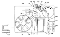
- FIG. 1 is a schematic block diagram of the automatic analyzer 100 in the first embodiment.
- the automatic analyzer 100 is used for analysis, and a sample container transport unit 102 a that transports a sample container 101 such as a blood collection tube containing a sample to be analyzed to a sample aspiration position (sample dispensing position) 110.
- a sample container transport unit 102 a that transports a sample container 101 such as a blood collection tube containing a sample to be analyzed to a sample aspiration position (sample dispensing position) 110.
- the dispensing unit 105 is provided with a reagent dispensing unit 106 for dispensing the reagent in the reagent container 103 into the reaction container 107 b.
- the automatic analyzer 100 installs a reaction container 107b containing a reaction solution in which a sample and a reagent are mixed, and controls the reaction acceleration unit (reaction unit to control the temperature of the reaction solution to fall within a certain temperature range And 107) and a measuring unit 108 for optically measuring the amount of the substance in the reaction solution in which the reaction is promoted by the reaction promoting unit 107. These units are controlled by the controller 113.
- the reagent storage unit 104 may, for example, arrange a plurality of reagent containers 103 on the circumference and convey any reagent container 103 to a desired position by rotating the reagent containers 103.
- a configuration may be employed in which a plurality of rows are arranged vertically and horizontally.
- the measurement unit 108 performs optical measurement on the reaction liquid in the measurement channel in the measurement unit 108.
- measurement operation of the measurement unit 108 measurement of the absorbance of the reaction solution, addition of a reagent to the reaction solution, measurement of the amount of luminescence when voltage is applied, measurement of the number of particles in the reaction solution, or reaction solution It is possible to measure the fluctuation of the current value or the voltage value when the electrode contacts the electrode film.
- a photometer such as a photomultiplier tube or a photometer
- an imaging device such as a CCD
- an ammeter for measuring fluctuations in current value or voltage value a voltmeter, etc.
- the reaction promoting unit 107 causes a stable reaction to proceed by maintaining the temperature of the reaction vessel 107b within a predetermined temperature range.
- the incubator may be an incubator whose temperature is controlled by heating the surroundings using a heater or the like in a state where a plurality of reaction vessels 107b are arranged on the circumference, or a liquid controlled to a certain temperature range is circulated
- the reaction vessel may be a constant temperature bath in which the reaction vessel is immersed.
- sample dispensing unit 105 dispenses the sample in consideration of the effect of carryover between the samples, it is replaced every time the sample comes in contact with the sample.
- a possible dispensing tip may be used, or an unused reaction container 107b may be used each time for the reaction container 107b for reacting the sample with the reagent.
- the sample container transport unit 102a transports, for example, a sample rack 109a on which one or a plurality of sample containers 101 is mounted, to a suction position of the sample dispensing unit 105 along a linear transport trajectory 114a by the transport belt mechanism.
- the sample container transport unit 102a is installed such that the transport locus 114a of the sample container transport unit 102a intersects the predetermined sample suction position 100.
- the movement trajectory 115 of the dispensing nozzle is a trajectory passing through the sample suction position 115 and the sample discharge position 107a.
- the sample container 101 that can be used in the automatic analyzer 100 can use a plurality of types of sample containers 101 instead of a single type of sample container 101.
- the sample container 101 is mounted and transported to a sample rack 109 a on which five sample containers 101 can be mounted.
- the sample rack 109a is carried in to the automatic analyzer 100 from the sample transport system 118a-1 connected to the left side of the automatic analyzer 100 in FIG.
- the sample container transport unit 102 a moves in the direction indicated by the arrow 116 and transports it to the sample dispensing position 110.
- sample dispensing is performed at the sample dispensing position 110, the sample is moved in the direction indicated by the arrow 117, and is transported to the sample transport system 118a-2 connected to the right side of FIG. 1 of the automatic analyzer 100. It is carried out of the analyzer 100.
- sample transport system of the inspection system connected to the automatic analyzer 100 in the example shown in FIG. 1, sample transport systems 118a-1 and 118a-2), It is necessary to change the loading direction and the unloading direction.
- FIG. 2 is a schematic configuration diagram of the automatic analyzer 100 in the first embodiment when a sample transport system different from the example shown in FIG. 1 is applied.
- the sample rack 109b which is loaded from the sample transport system 118b-1 connected to the right side of the automatic analyzer 100 and on which one or more sample containers 101 are mounted is the sample transport system 118b-2, 1118b-3. After being carried into the sample container transport unit 102b of the automatic analyzer 100 through the above, it is transported to the sample dispensing position 110 along the linear transport locus 114b.
- the sample rack 109b is transported in the reverse direction 117b to the transport direction 116b to the sample dispensing position 110, and the sample rack 101b is transferred from the sample transport system 118b-3 to the sample container 101. Is returned to the same place as the position where the sample was carried in and taken out of the automatic analyzer 100. Thereafter, the sample is transported to the sample transport system 118b-4 via the sample transport systems 118b-3 and 118b-2.
- the sample rack 109a is carried in from the sample conveyance system 118a-1 connected to the left side of the automatic analyzer 100, and carried out to the sample conveyance system 118a-2 connected on the right side.
- the sample conveyance system 118a-1 connected to the left side of the automatic analyzer 100
- the sample conveyance system 118a-2 connected on the right side.
- FIG. 3 is a schematic configuration diagram of an automatic analyzer in the case where a sample transport system different from the example shown in FIG. 1 is applied in the first embodiment.
- FIG. 3 after the sample rack 109c is transferred from the sample transport systems 118c-1 and 118c-3 connected to the left side of the automatic analyzer 100 to the sample container transfer unit 102c of the automatic analyzer 100, as indicated by an arrow 116c. , Moved along the transport track 114c, moved from the detection suction position 110 as indicated by the arrow 117c, and may be carried out to the sample transport system 118c-2 connected to the left side of the automatic analyzer 100. .
- a buffer area 119 for temporarily storing the sample rack 109c in which the sample container 101 is installed is provided, and the sample rack 109c is transported from the buffer area 119 to the automatic analyzer 100, or from the automatic analyzer 100.
- the sample rack 109 c may be transported to the buffer area 119.
- the automatic analyzer shown in FIGS. 1, 2, and 3 uses sample container transport units 102a, 102b, and 102c having different shapes, components, and structures, but the trajectory of the dispensing nozzle of the sample dispensing unit 105
- the point at which the sample aspirating position 110, which is the point of intersection between the sample container transporting unit 102a, 102b and 102c and the transportation locus 114a, 114b and 114c of the sample container transporting unit 102a, 102b and 102c, or a contact point are arranged so that the relative positions with the other units constituting the same are the same.
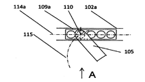
- FIG. 4A and 4B show the sample aspiration position 110 and the transport locus 114a of the sample container 101 of the sample container transport unit 102a when the sample container transport unit 102a is attached to the automatic analyzer 100 in the example shown in FIG. Is an explanatory view of a configuration that allows the intersection to be reliably made.
- the second sample container 101 from the left in FIG. 4A of the plurality of sample containers 101 on the sample rack 109a is the sample aspirating unit 105 at the position for suctioning the sample from the sample suctioning position 110; A plan view showing the position 110 is shown.
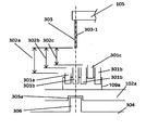
- FIG. 4B shows an arrow view seen from the direction A of the plan view shown in FIG. 4A.
- a pin 306 projecting upward is formed on the attachment surface 304 of the sample container transport unit 102a of the automatic analyzer 100 below the sample suction position 110.
- the shape of the pin 306 may be cylindrical or prismatic. As an example of the dimensions, one having a diameter of 10 mm and a height of 10 mm can be considered, but other dimensions may be possible.
- a hole 305 a for inserting a pin 306 is formed on the back surface of the sample container transport unit 102 a and on the surface facing the mounting surface 304 of the automatic analyzer 100.
- the hole 305 a may be circular or polygonal and may have the same shape as the pin 306.
- the sample dispensing unit 105 extends downward and has a sample dispensing nozzle 303 for dispensing a sample, and when the sample dispensing nozzle 303 is positioned at the sample aspiration position 110, The pin 306 is formed at a position where the extension of the central axis 303-1 is parallel to the central axis of the pin 306.
- the pin 306 and the hole 305a are positioned at the position of the sample container transport unit 102a by fitting the holes 305a formed in the sample container transport unit 102a to the pins 306.
- the sample container transport unit 102a can be disposed at an appropriate position.
- the sample container transport unit 102a has a transport belt or the like for transporting the sample rack 109a in a state where the pin 306 is fitted in the hole 305a, although it is omitted for the sake of illustration, and is mounted on the sample rack 109a.
- Each of the plurality of sample containers 101 can be positioned at the sample suction position 110.
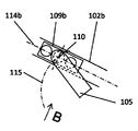
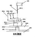
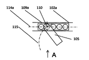
- FIGS. 5A and 5B are configured such that when the sample container transport unit 102b is attached to the automatic analyzer 100, the sample suction position 110 and the transport trajectory 114b of the sample container 101 of the sample container transport unit 102b can surely cross each other.
- FIG. 5A is configured such that when the sample container transport unit 102b is attached to the automatic analyzer 100, the sample suction position 110 and the transport trajectory 114b of the sample container 101 of the sample container transport unit 102b can surely cross each other.
- the second sample container 101 from the left in FIG. 5A of the plurality of sample containers 101 on the sample rack 109b is the sample aspirating unit 105 at the position for suctioning the sample from the sample suctioning position 110; A plan view showing the position 110 is shown.
- FIG. 5B the arrow line view seen from the B direction of the top view shown to FIG. 5A is shown by FIG. 5B.
- the pin 306 projecting upward is formed on the attachment surface 304 of the sample container transport units 102a and 102b of the automatic liquid separation apparatus 100 below the sample suction position 110. There is.
- a hole 305 b for inserting the pin 306 is formed on the back surface of the sample container transport unit 102 b and on the surface facing the mounting surface 304 of the automatic analyzer 100.
- the hole 305 b may be circular or polygonal and may have the same shape as the pin 306.
- the pin 306 and the hole 305b serve as an alignment mechanism for the sample container transport unit 102b, and the pin 306 is fitted with the hole 305b formed in the sample container transport unit 102b. By doing this, the sample container transport unit 102b can be disposed at an appropriate position.
- the sample container transport unit 102b has a transport belt or the like for transporting the sample rack 109b in a state in which the pin 306 is fitted in the hole 305b, although not shown because of illustration, and is mounted on the sample rack 109b.
- Each of the plurality of sample containers 101 can be positioned at the sample suction position 110.
- a plurality of types of sample containers 101 can be used.
- the relative positions in the direction of gravity of the injection nozzle 303 and the sample container 101 can be configured to be the same.
- the samples of the same type In the case of the container 301a, the distance 302a between the sample dispensing nozzle 303 and the sample container 301a can be the same distance.
- the distance 302 b can be used, and for the container 301 c, the distance 302 c can be used.
- the relative positions between the components of the sample dispensing unit 105 and the sample container transport units 102a and 102b during sample dispensing operation, and sample dispensing can be made the same, and the stability of the same sample dispensing operation can be ensured before and after the change of the sample container transport unit.
- the positional relationship between the sample container transport units 102a and 102b and the dispensing nozzle 303 can be more accurately matched.
- the sample dispensing unit relating to cleaning or replacement of the unit for which the operator performs maintenance work for example, the sample dispensing nozzle 303, replacement of consumables, etc.
- the unit 105, the consumables storage unit 111, and the like use units having the same configuration, and the relative positions between the units are also the same.
- the maintenance operation procedure for the sample container transport unit 102a or 102b etc. does not change. There is no need to remember new work procedures and the like, and the burden on the operator associated with the change of the inspection system can be reduced.
- the sample container transport unit 102c shown in FIG. 3 has the same configuration as that shown in FIGS. 4A and 4B, so the illustration and the detailed description will be omitted.
- the sample container transport units 102a and 102b shown in FIGS. 4A, 4B, 5A and 5B have a structure for moving the sample racks 109a and 109b on which the sample containers 101 are mounted on the rack transport surface.
- the invention is not limited to this structure.
- FIG. 17 is an explanatory view of a configuration in which the circular conveyance trajectory 114d of the sample container 101 of the conveyance unit 401 can be reliably intersected.
- the sample dispensing unit 105 at the position for suctioning the sample from the sample suction position 110 and the sample container 101 among the plurality of sample containers 101 on the sample container transport unit 401 are located at the sample suction position 110.
- the top view which shows the state to be done is shown.
- FIG. 6B shows a simplified cross-sectional view along the line CC of the plan view shown in FIG. 6A.
- a plurality of sample containers 101 are installed on the circumference of a circular sample container transport unit 401, and the sample containers 101 are transported along a transport trajectory 114d in the circumferential direction.
- the sample container transport unit 401 has a fixed portion 401f and a rotating portion 401r.
- the bottom surface of the fixing portion 401 f is formed with a hole 305 c that fits with a pin 306 formed on the mounting surface 304 of the automatic analyzer 100.
- a hole 305 c fitted with the pin 306 serves as an alignment mechanism of the sample container transport unit 401.
- the rotating unit 401 r rotates around the disk rotation center shaft 402 attached to the fixed unit 401 f and conveys the sample container 101 to the sample suction position 110.
- the relative positions in the gravity direction of the sample dispensing nozzle 303 of the sample dispensing unit 105 and the sample container 101 become the same. It can be configured.
- the distance 302a between the sample dispensing nozzle 303 and the sample container 301a can be the same distance as the sample container transport units 102a and 102b. That is, by adjusting the depth dimension of the hole 305c of the fixing portion 401f, the same distance 302a can be obtained in the case of the sample container 301a.
- the operator needs to newly learn the maintenance procedure for the sample container transport units 102a, 102b, 102c, and 401, the maintenance procedure for the other units in the automatic analyzer 100 does not change. There is no need to remember new work procedures and the like related to them, and the burden on the operator accompanying the change of the inspection system can be reduced.
- Example 2 Next, Example 2 will be described.
- FIGS. 7A and 7B show that when the sample container transport unit 102a is attached to the automatic analyzer 100 in the second embodiment, the sample aspiration position 110 and the transport trajectory 114a of the sample container 101 of the sample container transport unit 102a are assured. It is an explanatory view of composition which makes crossing possible.
- the second sample container 101 from the left in FIG. 7A of the plurality of sample containers 101 on the sample rack 109a is the sample aspirating unit 105 at the position for suctioning the sample from the sample suctioning position 110; A plan view showing the position 110 is shown.
- FIG. 7B shows an arrow view seen from the direction A of the plan view shown in FIG. 7A.
- a hole 305 c is formed in the attachment surface 304 of the sample container transport unit 102 a of the automatic liquid separation apparatus 100 below the sample suction position 110.
- the shape of the hole 305c may be cylindrical or prismatic. As an example of the dimensions, one having a diameter of 10 mm and a height of 10 mm can be considered, but other dimensions may be possible.
- a pin 306 to be inserted into the hole 305 c is formed on the back surface of the sample container transport unit 102 a and on the surface facing the mounting surface 304 of the automatic analyzer 100.
- the pin 306 may be circular or polygonal and may have the same shape as the hole 305c.
- the pin 306 and the hole 305c serve as an alignment mechanism for the sample container transport unit 102a, and the pin 306 is fitted in the hole 305c formed in the mounting surface 304.
- the sample container transport unit 102a can be disposed at an appropriate position.
- the other configuration is the same as that of the first embodiment, so the illustration and the detailed description will be omitted.
- the second embodiment forms the downwardly extending pins 306 as shown in FIG. 7B in the sample container transport units 102b, 102c, and 401, and forms the hole 305c in the mounting surface 304. Examples are also included.
- Example 3 Next, Example 3 will be described.
- Example 1 and Example 2 described above the positions of the pins 306 or holes 305c provided on the sample container transport units 102a, 102b, 102c, and 401 and the attachment surface 304 of the sample container transport unit of the automatic analyzer 100 It coincides with the extension of the axis 303-1 of the sample dispensing nozzle 303 located at the position 110.
- the sample container transport units 102 a, 102 b, 102 c, 401 are arranged such that the transport paths 114 a, 114 b, 114 c, 114 d of the sample suction position 110 and the sample container transport units 102 a, 102 b, 102 c, 401 intersect the sample suction position 110.
- the position of the pin 306 or the hole 305 c may not be aligned with the extension of the axis 303-1 of the sample dispensing nozzle 303 located at the sample aspiration position 110, as long as it can be positioned.
- the third embodiment is an example in which the formation position of the pin or the hole does not coincide with the extension of the axis 303-1 of the sample dispensing nozzle 303.
- FIG. 8 is an explanatory diagram of the third embodiment, and in the case where the formation position of the pin or the hole in the sample container transport unit 102a does not coincide with the extension of the axis 303-1 of the sample dispensing nozzle 303,
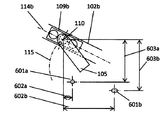
- FIG. 9 is a schematic plan view, and
- FIG. 9 is a schematic plan view of an example of the case where the sample container transport unit 102b is not the same as the example of FIG.
- reference numerals 601 a and 601 b are views showing the positions where the pins 306 and the holes 305 a are formed as shown in FIG. 4B from above.
- the combined position 601a of the pin and the hole indicates the position where the pin 306 is formed on the mounting surface 306 and the hole 305a is formed on the back surface of the sample container transport unit 102a.
- the position 601a has the sample suction position 110 as the origin, and the horizontal distance on the paper surface of FIG. 8 is 602a from this origin, and the vertical distance is 603a (a certain horizontal distance from the sample suction position 110). position).
- the combined position 601b of the pin and the hole also indicates the position where the pin 306 is formed on the attachment surface 306 and the hole 305a is formed on the back surface of the sample container transport unit 102a.
- the position 601b has the sample suction position 110 as an origin, and the horizontal distance on the sheet of FIG. 8 from this origin is 602b, and the vertical distance is 603b.
- the combined position 601a of the pin and the hole indicates the position where the pin 306 is formed on the attachment surface 306 and the hole 305a is formed on the back surface of the sample container transport unit 102b.
- the position 601a has the sample suction position 110 as the origin, and the horizontal distance on the sheet of FIG. 9 is 602a from this origin and the vertical distance is 603a.
- the combined position 601b of the pin and the hole also indicates the position where the pin 306 is formed on the attachment surface 306 and the hole 305a is formed on the back surface of the sample container transport unit 102a.
- the position 601b has the sample suction position 110 as the origin, and the horizontal distance on the sheet of FIG. 9 is 602b from the origin, as in the example shown in FIG. 8, and the vertical distance is 603b.
- the other configuration is the same as that of the first embodiment, so the illustration and the detailed description thereof will be omitted.
- the illustrated example is an example in the case of being applied to the sample container transport units 102a and 102b
- the third embodiment is also applicable to the sample container transport units 102c and 401.
- the pin and the hole serve as the alignment mechanism of the sample container transport units 102a and 102b, and the same effect as the first embodiment can be obtained.
- the combination position of the pin and the hole is two points, the alignment of the sample container transport units 102a, 102b, 102c, and 401 can be performed with higher accuracy.
- Examples 1 to 3 described above are examples in which the pin and the hole are fitted to perform alignment of the sample container transport unit.
- Example 4 uses the alignment jig instead of the pin. It is an example which performs position alignment of a container conveyance unit.
- 10A, 10B, 11A and 11B are explanatory diagrams of the fourth embodiment.
- FIG. 10A the second sample from the left among the plurality of sample containers 101 on the sample rack 109a transported by the sample container transport unit 102d and the sample dispensing unit 105 at a position where the sample is aspirated from the sample aspiration position 110.
- a plan view showing a state in which the sample container 101 is located at the sample aspiration position 110 is shown.
- FIG. 10B shows an arrow view seen from the direction A of the plan view shown in FIG. 10A.
- a hole 305e is formed in the attachment surface 304 of the sample container transport unit 102d, and a hole 305d is formed in the back surface of the sample container transport unit 102d.
- the holes 305e and 305d and the alignment jig 307a form an alignment mechanism, and the alignment jig 307a is installed in both holes of the holes 305e and 305d.
- the sample container transport unit 102d can be positioned with respect to the sample suction position 110.
- the alignment jig 307a may have a cylindrical shape or a prismatic shape, and the shape of the alignment jig 307a and the shapes of the holes 305d and 305e are matched.
- FIG. 11A and FIG. 111B are diagrams showing a modification in the case of performing alignment using an alignment jig.
- FIG. 11A the second sample from the left among the plurality of sample containers 101 on the sample rack 109a transported by the sample container transport unit 102d and the sample dispensing unit 105 at a position where the sample is aspirated from the sample aspiration position 110.
- a plan view showing a state in which the sample container 101 is located at the sample aspiration position 110 is shown.
- FIG. 11B shows an arrow view seen from the direction A of the plan view shown in FIG. 11A.
- a hole 305f is formed in the sample container transport unit 102e, and the hole 305f is moved to a position that will be the sample suction position 110.
- adjustment allowances 501a, 501b, and 501c whose positions can be adjusted in the illustrated arrow direction are formed.
- the positioning jig 307b is used to fix the sample container transport unit 102e while adjusting the position of the sample container transport unit 102e.
- the alignment jig 307 b has a settable hole or pin so that the axis of the sample dispensing nozzle 303 is the same as that of the axis 303-1.
- the alignment jig 307a and the hole 307f form an alignment mechanism, and the projection 505 of the alignment jig 307a is transported to the sample container Insert the sample container conveyance unit 102e in the direction of the adjustment allowances 501a and 502b so that the axis of the alignment jig 307b and the axis 303-1 of the dispensing nozzle 303 coincide with the hole 305f of the unit 102e. Move and adjust the position.
- a representative dimension 502 of the distance between the sample dispensing nozzle 303 and the installation surface of the sample rack of the sample container transport unit 102e is formed in the alignment jig 307b.
- One of the representative dimensions 502 is, for example, the distance between the tip of the sample dispensing nozzle 303 when the reset operation of the automatic analyzer 100 ends and the rack installation surface of the sample container transport unit 102e.
- a surface 504 of a concave portion (in the illustrated example, a surface having a surface on which the sample dispensing nozzle 303 can contact at a distance equal to the representative dimension 502 from the installation surface 503 of the alignment jig 307b to the sample container transport unit 102e). Adjust the position by moving the sample container transport unit 102e in the direction of the adjustment margin 501c so that the tip of the sample dispensing nozzle 303 is in contact with the bottom surface of the recess into which the sample dispensing nozzle 303 is inserted. Do.
- the sample container transport unit 102e can be fixed after the sample container transport unit 102e is moved in the directions of the adjustment allowances 501a, 501b, and 501c in the above-described procedure.
- the sample container transport unit can be positioned at the sample suction position 110 which is an intersection point of the movement trajectory of the nozzle 303 of the detection and dispensing unit 105 and the sample container transport trajectory of the sample container transport unit 102a etc. Since the positioning member such as the pin 306 and the hole 305a which can be fitted with the pin 306 is provided, the sample dispensing unit 105 and the sample container at the time of sample dispensing operation even when the type of sample container transport unit is different.
- the relative positions among the components of the transport units 102a, 102b, 102c, 102d, and 401, and the drive conditions for moving the respective axes of the sample dispensing unit 105 can be made the same, and before and after the change of the sample container transport unit The stability of the same sample dispensing operation can be secured.
- sample container transport unit 101: sample container, 102a, 102b, 102c, 102d, 102e: sample container transport unit, 103: reagent container, 104: reagent storage unit, 105 .
- Sample transport system 119 Buffer area 301a, 301b, 301c: sample container 303: sample dispensing nozzle 304: mounting surface of sample container transport unit 305a, 305b, 305c, 305d, 305e, 305f: hole, 306: pin, 307a, 307b: alignment jig, 401: sample container transport unit, 402: central axis of disk rotation, 501a, 501b, 501c ... Adjustment fee
Landscapes
- Physics & Mathematics (AREA)
- Health & Medical Sciences (AREA)
- Life Sciences & Earth Sciences (AREA)
- Chemical & Material Sciences (AREA)
- Analytical Chemistry (AREA)
- Biochemistry (AREA)
- General Health & Medical Sciences (AREA)
- General Physics & Mathematics (AREA)
- Immunology (AREA)
- Pathology (AREA)
- Automatic Analysis And Handling Materials Therefor (AREA)
Abstract
Description
反応容器が設置され、上記反応容器内の検体の反応を促進する反応ユニットと、
予め定めた検体吸引位置に位置する検体容器から検体を吸引し、上記反応ユニットに設置された反応容器に分注する検体分注ユニットと、上記反応容器内の反応液を測定する測定ユニットと、上記検体吸引位置と上記検体容器搬送ユニットの検体容器搬送軌跡とが交差するように、上記検体容器搬送ユニットの位置合わせを行うための位置合わせ機構と、を備える。
図1は、実施例1における自動分析装置100の概略構成図である。
次に、実施例2について説明する。
次に、実施例3について説明する。
次に、実施例4について説明する。
Claims (13)
- 検体容器を搬送する検体容器搬送ユニットと、
反応容器が設置され、上記反応容器内の検体の反応を促進する反応ユニットと、
予め定めた検体吸引位置に位置する検体容器から検体を吸引し、上記反応ユニットに設置された反応容器に分注する検体分注ユニットと、
上記反応容器内の反応液を測定する測定ユニットと、
上記検体吸引位置と上記検体容器搬送ユニットの検体容器搬送軌跡とが交差するように、上記検体容器搬送ユニットの位置合わせを行うための位置合わせ機構と、
を備えることを特徴とする自動分析装置。 - 請求項1に記載の自動分析装置において、
上記位置合わせ機構は、互いに嵌合するピンと穴であることを特徴とする自動分析装置。 - 請求項2に記載の自動分析装置において、
上記位置合わせ機構のピンは、自動分析装置の検体容器搬送ユニット取付け面に形成され、上記位置合わせ機構の穴は上記検体容器搬送ユニットに形成されることを特徴とする自動分析装置。 - 請求項2に記載の自動分析装置において、
上記位置合わせ機構の穴は、自動分析装置の検体容器搬送ユニット取付け面に形成され、上記位置合わせ機構のピンは上記検体容器搬送ユニットに形成されることを特徴とする自動分析装置。 - 請求項3に記載の自動分析装置において、
上記位置合わせ機構のピンは、自動分析装置の検体容器搬送ユニット取付け面の上記検体吸引位置の下方に形成されることを特徴とする自動分析装置。 - 請求項4に記載の自動分析装置において、
上記位置合わせ機構の穴は、自動分析装置の検体容器搬送ユニット取付け面の上記検体吸引位置の下方に形成されることを特徴とする自動分析装置。 - 請求項3又は4に記載の自動分析装置において、
上記位置合わせ機構のピンと穴との組み合わせを複数有することを特徴とする自動分析装置。 - 請求項7に記載の自動分析装置において、
上記位置合わせ機構は、上記検体吸引位置から一定の水平距離だけ離間した位置に形成されることを特徴とする自動分析装置。 - 請求項1に記載の自動分析装置において、
上記位置合わせ機構は、自動分析装置の検体容器搬送ユニット取付け面に形成された穴と、上記検体容器搬送ユニットに形成された穴と、上記検体容器搬送ユニット取付け面に形成された穴および上記検体容器搬送ユニットに形成された穴に挿入される位置合わせ治具とを有することを特徴とする自動分析装置。 - 請求項1に記載の自動分析装置において、
上記検体分注ユニットは、下方向に延びる検体分注ノズルを有し、上記位置合わせ機構は、上記検体容器搬送ユニットに形成された穴と、この穴に挿入される突出部及び上記検体分注ノズルが挿入される凹部を有する位置合わせ治具とを有することを特徴とする自動分析装置。 - 請求項2に記載の自動分析装置において、
上記検体分注ユニットは、下方向に延びる検体分注ノズルを有し、上記位置合わせ機構は、上記検体吸引位置に位置された検体容器と上記検体分注ノズルの先端との距離が、複数種類の上記検体容器搬送ユニットについて、互いに略同一となるように、上記穴とピンとの寸法が設定されていることを特徴とする自動分析装置。 - 請求項1に記載の自動分析装置において、
上記検体容器搬送ユニットは、上記検体容器を複数搭載する検体ラックを直線状の搬送軌跡に沿って搬送することを特徴とする自動分析装置。 - 請求項1に記載の自動分析装置において、
上記検体容器搬送ユニットは、上記検体容器を円形状の搬送軌跡に沿って搬送することを特徴とする自動分析装置。
Priority Applications (4)
| Application Number | Priority Date | Filing Date | Title |
|---|---|---|---|
| CN201880058578.9A CN111164431B (zh) | 2017-10-11 | 2018-07-06 | 自动分析装置 |
| US16/644,111 US11686741B2 (en) | 2017-10-11 | 2018-07-06 | Automatic analyzer |
| EP18865969.2A EP3696552B1 (en) | 2017-10-11 | 2018-07-06 | Automatic analysis device |
| JP2019547912A JP6783951B2 (ja) | 2017-10-11 | 2018-07-06 | 自動分析装置 |
Applications Claiming Priority (2)
| Application Number | Priority Date | Filing Date | Title |
|---|---|---|---|
| JP2017197841 | 2017-10-11 | ||
| JP2017-197841 | 2017-10-11 |
Publications (1)
| Publication Number | Publication Date |
|---|---|
| WO2019073644A1 true WO2019073644A1 (ja) | 2019-04-18 |
Family
ID=66100495
Family Applications (1)
| Application Number | Title | Priority Date | Filing Date |
|---|---|---|---|
| PCT/JP2018/025704 Ceased WO2019073644A1 (ja) | 2017-10-11 | 2018-07-06 | 自動分析装置 |
Country Status (5)
| Country | Link |
|---|---|
| US (1) | US11686741B2 (ja) |
| EP (1) | EP3696552B1 (ja) |
| JP (1) | JP6783951B2 (ja) |
| CN (1) | CN111164431B (ja) |
| WO (1) | WO2019073644A1 (ja) |
Cited By (3)
| Publication number | Priority date | Publication date | Assignee | Title |
|---|---|---|---|---|
| CN113063956A (zh) * | 2021-03-22 | 2021-07-02 | 山东艾科达生物科技有限公司 | 一种凝血仪联检系统及其使用方法 |
| JP2021139825A (ja) * | 2020-03-09 | 2021-09-16 | 株式会社日立ハイテク | 自動分析装置 |
| CN114859030A (zh) * | 2022-04-02 | 2022-08-05 | 深圳市帝迈生物技术有限公司 | 一种样本检测装置 |
Families Citing this family (1)
| Publication number | Priority date | Publication date | Assignee | Title |
|---|---|---|---|---|
| CN117147900B (zh) * | 2023-08-31 | 2025-04-01 | 中元汇吉生物技术股份有限公司 | 样本分析系统 |
Citations (7)
| Publication number | Priority date | Publication date | Assignee | Title |
|---|---|---|---|---|
| US4046248A (en) * | 1974-01-15 | 1977-09-06 | Chemcut Corporation | Connecting and alignment means for modular chemical treatment system |
| JPS5439107B2 (ja) | 1974-10-15 | 1979-11-26 | ||
| JPH03285175A (ja) * | 1990-03-30 | 1991-12-16 | Shimadzu Corp | 自動分析装置 |
| JPH10325839A (ja) * | 1997-03-26 | 1998-12-08 | Hitachi Ltd | 検体分析システム |
| JP2000028621A (ja) * | 1998-07-15 | 2000-01-28 | Hitachi Ltd | 検体処理システム |
| US20060083660A1 (en) * | 2004-03-31 | 2006-04-20 | Roche Molecular Systems, Inc. | Modular apparatus |
| JP2008180638A (ja) * | 2007-01-25 | 2008-08-07 | Olympus Corp | 自動分析装置 |
Family Cites Families (15)
| Publication number | Priority date | Publication date | Assignee | Title |
|---|---|---|---|---|
| US4325910A (en) | 1979-07-11 | 1982-04-20 | Technicraft, Inc. | Automated multiple-purpose chemical-analysis apparatus |
| US5207986A (en) | 1990-03-30 | 1993-05-04 | Shimadzu Corporation | Automatic analyzer |
| DE69434638T2 (de) * | 1993-09-24 | 2006-12-14 | Abbott Laboratories, Abbott Park | Betriebsverfahren für ein automatisches Analysesystem mit ständigem und wahlfreiem Zugriff zur gleichzeitigen Durchführung mehrerer Bestimmungen an einer Vielzahl flüssiger Proben |
| JPH07234226A (ja) * | 1994-02-25 | 1995-09-05 | Hitachi Ltd | 生体成分分析装置 |
| JP3294991B2 (ja) * | 1995-05-29 | 2002-06-24 | 株式会社日立製作所 | デイスポーザブルな反応容器を用いる分析装置 |
| JP4254994B2 (ja) * | 1995-05-29 | 2009-04-15 | 株式会社日立製作所 | デイスポーザブルな反応容器を用いる分析装置 |
| JP4101466B2 (ja) * | 1998-07-27 | 2008-06-18 | 株式会社日立製作所 | 生体サンプルの分析装置 |
| JP4110082B2 (ja) * | 2003-12-05 | 2008-07-02 | 株式会社日立ハイテクノロジーズ | 自動分析装置 |
| CA2842402C (en) | 2005-03-10 | 2016-02-23 | Gen-Probe Incorporated | Systems and methods to perform assays for detecting or quantifying analytes within samples |
| JP4945342B2 (ja) * | 2007-06-28 | 2012-06-06 | 株式会社日立ハイテクノロジーズ | 自動分析装置、および自動分析装置の分注方法 |
| EP2439537A1 (en) * | 2009-06-04 | 2012-04-11 | Universal Bio Research Co., Ltd. | Specimen testing device and method therefor |
| JP2010286420A (ja) * | 2009-06-15 | 2010-12-24 | Hitachi High-Technologies Corp | 分注ノズルの洗浄方法,自動分析装置、および容器 |
| JP5439107B2 (ja) | 2009-09-30 | 2014-03-12 | シスメックス株式会社 | ラック回収ユニット |
| JP6272645B2 (ja) * | 2012-12-14 | 2018-01-31 | 株式会社日立ハイテクノロジーズ | 自動分析装置 |
| JP6201581B2 (ja) * | 2013-09-27 | 2017-09-27 | 東ソー株式会社 | 自動分析装置 |
-
2018
- 2018-07-06 CN CN201880058578.9A patent/CN111164431B/zh active Active
- 2018-07-06 JP JP2019547912A patent/JP6783951B2/ja active Active
- 2018-07-06 EP EP18865969.2A patent/EP3696552B1/en active Active
- 2018-07-06 US US16/644,111 patent/US11686741B2/en active Active
- 2018-07-06 WO PCT/JP2018/025704 patent/WO2019073644A1/ja not_active Ceased
Patent Citations (7)
| Publication number | Priority date | Publication date | Assignee | Title |
|---|---|---|---|---|
| US4046248A (en) * | 1974-01-15 | 1977-09-06 | Chemcut Corporation | Connecting and alignment means for modular chemical treatment system |
| JPS5439107B2 (ja) | 1974-10-15 | 1979-11-26 | ||
| JPH03285175A (ja) * | 1990-03-30 | 1991-12-16 | Shimadzu Corp | 自動分析装置 |
| JPH10325839A (ja) * | 1997-03-26 | 1998-12-08 | Hitachi Ltd | 検体分析システム |
| JP2000028621A (ja) * | 1998-07-15 | 2000-01-28 | Hitachi Ltd | 検体処理システム |
| US20060083660A1 (en) * | 2004-03-31 | 2006-04-20 | Roche Molecular Systems, Inc. | Modular apparatus |
| JP2008180638A (ja) * | 2007-01-25 | 2008-08-07 | Olympus Corp | 自動分析装置 |
Non-Patent Citations (1)
| Title |
|---|
| See also references of EP3696552A4 |
Cited By (4)
| Publication number | Priority date | Publication date | Assignee | Title |
|---|---|---|---|---|
| JP2021139825A (ja) * | 2020-03-09 | 2021-09-16 | 株式会社日立ハイテク | 自動分析装置 |
| JP7309637B2 (ja) | 2020-03-09 | 2023-07-18 | 株式会社日立ハイテク | 自動分析装置 |
| CN113063956A (zh) * | 2021-03-22 | 2021-07-02 | 山东艾科达生物科技有限公司 | 一种凝血仪联检系统及其使用方法 |
| CN114859030A (zh) * | 2022-04-02 | 2022-08-05 | 深圳市帝迈生物技术有限公司 | 一种样本检测装置 |
Also Published As
| Publication number | Publication date |
|---|---|
| EP3696552A1 (en) | 2020-08-19 |
| EP3696552A4 (en) | 2021-06-16 |
| CN111164431B (zh) | 2023-08-01 |
| US11686741B2 (en) | 2023-06-27 |
| CN111164431A (zh) | 2020-05-15 |
| JPWO2019073644A1 (ja) | 2020-07-09 |
| JP6783951B2 (ja) | 2020-11-18 |
| US20200209272A1 (en) | 2020-07-02 |
| EP3696552B1 (en) | 2026-03-25 |
Similar Documents
| Publication | Publication Date | Title |
|---|---|---|
| US5138868A (en) | Calibration method for automated assay instrument | |
| JP6783951B2 (ja) | 自動分析装置 | |
| JP3229498B2 (ja) | 検体の自動分析方法および装置 | |
| US5192506A (en) | Incubator port closure for automated assay system | |
| CN216133083U (zh) | 输送组件 | |
| JP6651380B2 (ja) | 臨床検査装置 | |
| CN101147071A (zh) | 生物样品的复合自动分析装置、自动分析方法以及反应杯 | |
| US20170176481A1 (en) | Systems and Methods for Automated Analysis | |
| JP6619133B2 (ja) | 分析装置の設置 | |
| CN106443038B (zh) | 具有两个温度传感器的移液装置 | |
| WO2020152991A1 (ja) | 自動分析システムおよび検体の搬送方法 | |
| JP6850155B2 (ja) | 自動分析装置 | |
| JP2003329695A (ja) | 生化学分析装置 | |
| JP2023081180A (ja) | 自動分析装置 | |
| WO2021131296A1 (ja) | 自動分析装置及び自動分析装置用の制御プログラム | |
| JP4908956B2 (ja) | 分注装置 | |
| CN113811777A (zh) | 自动分析装置 | |
| JP7595157B2 (ja) | 検体容器及び自動分析装置 | |
| JP2020003413A (ja) | キュベット搬送装置及び自動分析装置 | |
| EP4495605A1 (en) | Testing device | |
| US20250076330A1 (en) | Measuring chip, automatic analyzing apparatus, reaction cuvette, and automatic analyzing system | |
| JP2025035385A (ja) | 測定チップ、自動分析装置、及び、自動分析システム | |
| JP5321324B2 (ja) | 反応容器の供給手段を切り替え可能な自動分析装置 | |
| CN116745626A (zh) | 自动分析装置 |
Legal Events
| Date | Code | Title | Description |
|---|---|---|---|
| 121 | Ep: the epo has been informed by wipo that ep was designated in this application |
Ref document number: 18865969 Country of ref document: EP Kind code of ref document: A1 |
|
| DPE1 | Request for preliminary examination filed after expiration of 19th month from priority date (pct application filed from 20040101) | ||
| ENP | Entry into the national phase |
Ref document number: 2019547912 Country of ref document: JP Kind code of ref document: A |
|
| NENP | Non-entry into the national phase |
Ref country code: DE |
|
| ENP | Entry into the national phase |
Ref document number: 2018865969 Country of ref document: EP Effective date: 20200511 |
|
| WWG | Wipo information: grant in national office |
Ref document number: 2018865969 Country of ref document: EP |