WO2019073667A1 - パッチアンテナおよび車載用アンテナ装置 - Google Patents
パッチアンテナおよび車載用アンテナ装置 Download PDFInfo
- Publication number
- WO2019073667A1 WO2019073667A1 PCT/JP2018/028892 JP2018028892W WO2019073667A1 WO 2019073667 A1 WO2019073667 A1 WO 2019073667A1 JP 2018028892 W JP2018028892 W JP 2018028892W WO 2019073667 A1 WO2019073667 A1 WO 2019073667A1
- Authority
- WO
- WIPO (PCT)
- Prior art keywords
- metal
- metal wall
- radiation element
- patch antenna
- vehicle
- Prior art date
- Legal status (The legal status is an assumption and is not a legal conclusion. Google has not performed a legal analysis and makes no representation as to the accuracy of the status listed.)
- Ceased
Links
Images

Classifications
-
- H—ELECTRICITY
- H01—ELECTRIC ELEMENTS
- H01Q—ANTENNAS, i.e. RADIO AERIALS
- H01Q1/00—Details of, or arrangements associated with, antennas
- H01Q1/27—Adaptation for use in or on movable bodies
- H01Q1/32—Adaptation for use in or on road or rail vehicles
- H01Q1/325—Adaptation for use in or on road or rail vehicles characterised by the location of the antenna on the vehicle
- H01Q1/3283—Adaptation for use in or on road or rail vehicles characterised by the location of the antenna on the vehicle side-mounted antennas, e.g. bumper-mounted, door-mounted
-
- H—ELECTRICITY
- H01—ELECTRIC ELEMENTS
- H01Q—ANTENNAS, i.e. RADIO AERIALS
- H01Q1/00—Details of, or arrangements associated with, antennas
- H01Q1/42—Housings not intimately mechanically associated with radiating elements, e.g. radome
-
- H—ELECTRICITY
- H01—ELECTRIC ELEMENTS
- H01Q—ANTENNAS, i.e. RADIO AERIALS
- H01Q1/00—Details of, or arrangements associated with, antennas
- H01Q1/48—Earthing means; Earth screens; Counterpoises
-
- H—ELECTRICITY
- H01—ELECTRIC ELEMENTS
- H01Q—ANTENNAS, i.e. RADIO AERIALS
- H01Q19/00—Combinations of primary active antenna elements and units with secondary devices, e.g. with quasi-optical devices, for giving the antenna a desired directional characteristic
- H01Q19/10—Combinations of primary active antenna elements and units with secondary devices, e.g. with quasi-optical devices, for giving the antenna a desired directional characteristic using reflecting surfaces
- H01Q19/106—Combinations of primary active antenna elements and units with secondary devices, e.g. with quasi-optical devices, for giving the antenna a desired directional characteristic using reflecting surfaces using two or more intersecting plane surfaces, e.g. corner reflector antennas
-
- H—ELECTRICITY
- H01—ELECTRIC ELEMENTS
- H01Q—ANTENNAS, i.e. RADIO AERIALS
- H01Q9/00—Electrically-short antennas having dimensions not more than twice the operating wavelength and consisting of conductive active radiating elements
- H01Q9/04—Resonant antennas
- H01Q9/0407—Substantially flat resonant element parallel to ground plane, e.g. patch antenna
-
- H—ELECTRICITY
- H01—ELECTRIC ELEMENTS
- H01Q—ANTENNAS, i.e. RADIO AERIALS
- H01Q1/00—Details of, or arrangements associated with, antennas
- H01Q1/12—Supports; Mounting means
- H01Q1/22—Supports; Mounting means by structural association with other equipment or articles
- H01Q1/24—Supports; Mounting means by structural association with other equipment or articles with receiving set
- H01Q1/241—Supports; Mounting means by structural association with other equipment or articles with receiving set used in mobile communications, e.g. GSM
-
- H—ELECTRICITY
- H01—ELECTRIC ELEMENTS
- H01Q—ANTENNAS, i.e. RADIO AERIALS
- H01Q1/00—Details of, or arrangements associated with, antennas
- H01Q1/27—Adaptation for use in or on movable bodies
- H01Q1/32—Adaptation for use in or on road or rail vehicles
- H01Q1/3208—Adaptation for use in or on road or rail vehicles characterised by the application wherein the antenna is used
Definitions
- the present invention relates to a patch antenna and an on-vehicle antenna device.
- a patch antenna is known as a planar antenna having square or circular small-area radiating elements.
- the application of the patch antenna is wide, and Patent Document 1 can receive a circularly polarized signal of a satellite wave and a linearly polarized signal of a ground wave, and can reduce the height when placed. It is disclosed.
- the conventional patch antenna generally has a configuration including a plate-like radiating element and a plate-like ground plane disposed in parallel to the radiation element. Therefore, the directivity in the direction normal to the plate surface of the radiation element (90-degree elevation angle viewed from the center of the radiation element) is strong.
- the directivity of each azimuth in the direction of the plate surface which is the extension direction of the plate surface of the radiating element viewed from the center of the radiating element called Azimuth direction or azimuthal direction, that is, each orientation in the plate surface direction of the radiating element
- the directivity is relatively high in the direction parallel to the line connecting the center of the radiating element and the feeding point, but the gain is compared in the direction intersecting the line connecting the center of the radiating element and the feeding point Lower.
- a plate-like radiation element and a metal wall part provided outside the periphery of the radiation element such that the wall intersects with a line connecting the center of the radiation element and the feeding point.
- a patch antenna and
- the metal wall portion is provided on the outer side of the periphery of the radiation element so that the wall surface intersects with the line connecting the center of the radiation element and the feeding point.
- the metal wall portion can change the radiation characteristics of radio waves. Therefore, it is possible to realize a technique capable of improving the gain in the direction intersecting the line connecting the center of the radiation element and the feeding point in the plate surface direction of the radiation element.
- a second aspect of the present invention is the patch antenna according to the first aspect, wherein the metal wall portion protrudes in the radial direction from the radiation element.
- the metal wall portion protrudes in the radial direction from the radiation element, the radiation characteristic can be largely changed.
- a third aspect of the present invention is the patch antenna according to the first or second aspect, wherein the metal wall portion is disposed in electrical non-conduction with the ground plane.
- the metal wall portion is electrically disconnected from the ground plate. Therefore, the interaction between the metal wall portion and the ground plate functioning as the ground can be reduced or suppressed.
- a metal portion in which a base portion and the metal wall portion are formed of a bent-shaped metal, and the base plate is spaced apart from the base portion so as not to electrically connect with the metal portion. It is a patch antenna which concerns on a 3rd aspect provided with the antenna main-body part which is installed in a conduction
- the metal wall portion is disposed on both sides of the radiation element, and the metal portion has a central portion as the base portion and one end side and the other end side as the metal wall portion. It is a patch antenna concerning the 4th mode which has a bent shape.
- the metal wall can be formed by the bent metal, the metal wall can be easily manufactured.
- the arrangement configuration of the metal portion and the antenna main portion can also be a relatively simple structure. For this reason, it is possible to easily manufacture a patch antenna that exhibits the effects according to the first to third aspects.
- a sixth aspect of the present invention is the patch antenna according to any one of the first to fifth aspects, wherein the metal wall portion is configured as a metal thin film.
- the thickness of the metal wall can be reduced. Therefore, the patch antenna can be miniaturized.
- a seventh aspect of the present invention is an on-vehicle antenna device including the patch antenna according to any one of the first to sixth aspects, wherein a housing installed in a predetermined direction at a predetermined position of a vehicle; And a supporting portion for supporting the patch antenna such that the patch antenna is for vertical polarization.
- the seventh aspect it is possible to realize a vertically polarized on-vehicle antenna device in which the gain in the direction intersecting the line connecting the center of the radiation element and the feeding point in the plate surface direction of the radiation element is improved.
- FIG. 3 is a longitudinal sectional view of the in-vehicle antenna device taken along the III-III section of FIG. 2;
- FIG. 4 is an exploded view of the in-vehicle antenna device corresponding to FIG. 3;
- the longitudinal cross-sectional view which longitudinally cut the vehicle-mounted antenna apparatus of a modification along the VIII-VIII cross section of FIG. The gain characteristic graph at the time of using a vehicle-mounted antenna apparatus as a circular polarization antenna.
- the directions are defined as follows.
- the direction from the dielectric substrate 32 toward the radiation element 31 Is called "radial direction”.
- the radiation direction is not the two directions from the dielectric substrate 32 to the radiation element 31 and the direction from the radiation element 31 to the dielectric substrate 32, but the direction is fixed.
- left-handed orthogonal three axes are defined. The coordinate origin of the orthogonal three axes is taken as the plate surface center of the radiation element 31.
- reference directions indicating directions parallel to the directions of the orthogonal three axes are added to the respective drawings.
- the reference direction is used because the origin of the orthogonal three axes is exactly at the plate surface center of the radiation element 31. It is shown as a reference for direction only.
- the normal direction to the plate surface of the radiation element 31 is taken as the Z-axis direction, and the radial direction is taken as the Z-axis positive direction.
- the direction along the line connecting the center of the radiation element 31 and the feed point (also described as core wire attachment hole) 31h is taken as the X-axis direction (see FIG. 2).
- the direction from the center of the radiation element 31 toward the feed point 31h is The X axis is in the positive direction. It becomes obvious that the Y-axis direction and the Y-axis positive direction are three left-handed orthogonal axes and that the X-axis positive direction and the Z-axis positive direction are defined.
- the elevation angle 90 ° direction when the direction (plate surface direction) along the plate surface of the radiation element 31 is an azimuth as viewed from the center of the radiation element 31 (orthogonal three-axis origin)
- the direction from the center of the radiation element 31 toward the feeding point 31h is the positive direction of the X axis
- the positive direction of the X axis from the positive direction of the Z axis to the negative direction of the Z axis is 12 o'clock.
- the azimuth in the time direction is the Y-axis positive direction.
- the plate surface direction of the radiation element 31 may be called an azimuth direction, an azimuth direction, or the like.
- X-axis direction means a direction parallel to the X-axis, and includes ⁇ both directions of the X-axis positive direction and the X-axis negative direction. The same applies to the Y-axis direction and the Z-axis direction. Therefore, each axial direction is the reference direction shown in each figure.
- the E plane, which is the electric field surface of the radiation element 31, and the H plane, which is the magnetic field surface, are in the X axis direction and the Z axis direction
- the YZ direction plane including the XZ direction plane including the E plane and the Y axis direction and the Z axis direction is the H plane. If the E plane and the H plane are defined in another expression, the plane including the direction perpendicular to the plate surface of the radiating element 31 and the direction of the line connecting the center of the radiating element 31 and the feeding point 31 h is the E plane, A plane perpendicular to the E plane and including a direction perpendicular to the plate surface of the radiation element 31 is the H plane.
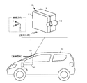
- FIG. 1 is a perspective external view showing a configuration example of the on-vehicle antenna device 10 of the present embodiment, and a conceptual view showing a usage example.
- the in-vehicle antenna device 10 is an antenna device provided with an in-vehicle antenna for V2X (Vehicle-to-everything) communication equipped with a patch antenna, and is installed in a predetermined direction at a predetermined position of the vehicle 3 via the coaxial cable 4 Are connected to the V2X controller 5.
- V2X Vehicle-to-everything
- the on-vehicle antenna device 10 is installed on an upper portion of a windshield (for example, near a rearview mirror) in a vehicle such that a radiation direction is directed to the front of the vehicle.
- a radiation direction is directed to the front of the vehicle.
- forward means the forward direction of the vehicle.
- the installation position and the installation number of the on-vehicle antenna device 10 can be appropriately changed according to the assumed environmental conditions such as the communication target. For example, multiple locations may be provided.
- the installation location may be, for example, the upper part of the dashboard, a bumper, a mounting portion of a license plate, a pillar portion such as an A-pillar, or the like.
- the on-vehicle antenna device 10 may be installed on the rear glass in the vehicle so that the radiation direction is directed to the rear of the vehicle.
- the term "rearward" means the backward direction of the vehicle.
- the on-vehicle antenna device 10 may be installed such that the radiation direction is directed to the right or left of the vehicle.
- the right direction means the right direction toward the forward direction of the vehicle
- the left direction means the left direction toward the forward direction of the vehicle.
- the on-vehicle antenna device 10 may be installed on the roof of a vehicle or the like.
- the on-vehicle antenna device 10 of the present embodiment has a rectangular parallelepiped appearance, and incorporates the patch antenna 20 in the case of the division structure of the first housing 11 and the second housing 12 divided in the radiation direction.
- the patch antenna 20 suitably functions as an antenna for vertical polarization by being mounted on the vehicle 3 by the support portion 13 for mounting on the vehicle body provided on the side of the housing.
- the support portion 13 is a boss for inserting a bolt or a screw used for installing the in-vehicle antenna device 10, and both left and right side surfaces (both side surfaces in the Y-axis direction) viewed from the vehicle 3.
- the configuration is provided for each, the setting position and the number of setting of the support portion 13 can be appropriately selected.
- the method of installing and fixing the in-vehicle antenna device 10 is not limited to the method using bolts and screws, and other methods may be used, and accordingly, the support portion 13 appropriately adopts a structure suitable for the method such as a clip structure. be able to.
- the support portion 13 supports the first housing 11 and the second housing 12 so that the first housing 11 and the second housing 12 are installed at a predetermined position of the vehicle 3 in a predetermined direction. That is, by placing the first housing 11 and the second housing 12 at a predetermined position of the vehicle 3 in a predetermined direction, the support 13 is patched so that the patch antenna 20 functions as an antenna for vertical polarization. It becomes suitable to support the antenna 20.
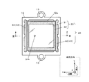
- FIG. 2 is a view for explaining an example of the internal configuration of the in-vehicle antenna device 10, in which the first housing 11 is removed and the inside of the second housing 12 is viewed from the Z-axis positive direction. is there.
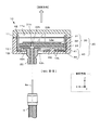
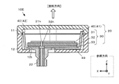
- FIG. 3 is a view for explaining an example of the internal configuration of the in-vehicle antenna device 10, and the in-vehicle antenna device 10 including the first housing 11 is taken along the III-III cross section of FIG. It is the longitudinal cross-sectional view cut longitudinally.
- FIG. 4 is an exploded view of the on-vehicle antenna device 10 including the first housing 11, and is an exploded view of the on-vehicle antenna device 10 shown in FIG.
- the first housing 11 defines an upper accommodation space 11 a which is a recess
- the second enclosure 12 defines a lower accommodation space 12 a which is a recess.
- the upper housing space 11 a and the lower housing space 12 a become one continuous housing space by assembling the first housing 11 and the second housing 12.
- the patch antenna 20 is installed so as to be mainly accommodated in the lower accommodation space 12 a in the accommodation space.
- the patch antenna 20 includes an antenna main body 30 and a metal portion 40 in order from the top toward the FIGS.
- the antenna main body 30 includes the radiation element 31, the dielectric substrate 32, and the ground plate 33 in order from the top toward the FIGS.
- the antenna main body 30 can be created by applying the method of manufacturing a printed circuit board, as in the conventional patch antenna.
- the radiation element 31 has a rectangular plate shape as viewed from the Z-axis positive direction, and is located at a position deviated from the center of the plate surface in the X-axis positive direction (direction along the polarization plane of the linear polarization of the patch antenna 20).
- a core wire attachment hole 31h which is a through hole in the Z-axis direction for inserting and fixing the core wire 4a of the coaxial cable 4 is provided.
- the core wire attachment hole 31 h serves as a feeding point. Therefore, the feeding point 31h will be appropriately described using the same reference numerals.
- FIGS. 3 and 4 although the thickness of the radiation element 31 and the ground plane 33 in the Z-axis direction is intentionally drawn large so that the structure can be easily understood, in practice the thin plate, ie, a thin film is formed You may
- the dielectric substrate 32 has a larger area than the radiation element 31 when viewed from the positive Z-axis direction.
- a core wire insertion hole 32 h penetrating in the Z-axis direction is provided at a position communicating with the core wire attachment hole 31 h of the radiation element 31.
- the ground plate 33 has the same shape as or a slightly smaller shape than the lower surface of the dielectric substrate 32 and has a core insertion hole 33 h communicating with the core attachment hole 31 h of the radiation element 31 and the core insertion hole 32 h of the dielectric substrate 32.
- the coaxial connector for substrate 22 is mounted on the lower surface of the base plate 33 through the insertion hole 12 h provided in the bottom of the second housing 12 so as to be coaxial with the core wire insertion hole 33 h.
- the core wire penetration hole 33h is illustrated on a large scale.
- the core wire insertion hole 33h corresponds to the core attachment hole 31h or the core insertion hole 32h. It may have the same diameter.
- the metal portion 40 is a sheet metal member in which both end portions in the X-axis direction are bent in the positive Z-axis direction.
- the base portion 49 and the first metal wall portion are formed by bending the central portion of the metal plate to the base portion 49 and bending one end side and the other end side in the Z-axis positive direction by 90 degrees or approximately 90 degrees, respectively.
- 41 and the second metal wall portion 42 are formed of bent metal. That is, the wall surfaces of the first metal wall portion 41 and the second metal wall portion 42 are provided in the direction along the H plane (the direction parallel or substantially parallel to the H plane).
- the metal portion 40 is not a sheet metal, and may be, for example, a resin on which a metal thin film is formed. Alternatively, a metal thin film may be formed on the inner surface of the second housing 12 (which may include the inner surface of the first housing 11) to form the metal portion 40. This eliminates the need for the sheet metal material, so the on-vehicle antenna device 10 can be miniaturized. Also in these cases, the base portion 49, the first metal wall portion 41, and the second metal wall portion 42 are formed as bent metal.
- the base portion 49 may be omitted, and the first metal wall portion 41 and the second metal wall portion 42 may be configured as a metal thin film. Furthermore, when only one of the first metal wall portion 41 and the second metal wall portion 42 is provided, one of them may be configured as a metal thin film.
- the first metal wall portion 41 and the second metal wall portion 42 are flat plate portions parallel or substantially parallel to each other.
- the lengths in the Z-axis direction of the first metal wall portion 41 and the second metal wall portion 42 are the upper surface of the antenna main body 30 (the upper end in FIG.
- the surface of the radiation element 31 is set to project in the positive Z-axis direction side with respect to the Z-axis positive direction end surface).
- a connector insertion hole 49h for inserting the substrate coaxial connector 22 and a protrusion 12t (see FIG. 4) which protrudes in the positive Z-axis direction from the bottom surface of the lower accommodation space 12a of the second housing 12 are inserted.
- the metal portion 40 is fixed to the bottom of the second housing 12 by aligning the projection insertion hole 49 j of the base 49 with the projection 12 t of the second housing 12 inserted.
- the fixing method may be appropriately selected, but for example, the metal portion 40 and the bottom of the second housing 12 may be bonded.
- the protrusion 12t protrudes in the positive Z-axis direction from the base 49, and the lower surface (surface of the ground plate 33: end surface in the negative Z-axis direction) of the antenna main body 30 abuts on the tip thereof.
- the part 12t is fixed.
- the fixing method may be appropriately selected, but for example, the antenna main body 30 and the protrusion 12t may be adhered.
- the distance from the upper surface (the end surface on the Z axis positive direction side) of the base portion 49 to the surface of the ground plane 33 be less than 2 mm.
- an interval is provided so that the outer peripheral portion of the antenna main body 30 does not contact the metal portion 40. That is, the antenna main body 30 and the substrate coaxial connector 22 are electrically disconnected from the metal portion 40.
- the space between the antenna main body 30 and the metal part 40 is a kind of a type that does not interfere with the propagation (conduction) of radio signals of V2X communication. It functions as a capacitor. Therefore, this space may be an air layer, that is, a space, or may be a resin layer which is an electrically insulating material. If a resin layer is used, the resin can also be used as a space replenisher and a bonding agent.
- the antenna main body 30 and the metal portion 40 are nonconductive, various advantages occur. For example, it is possible to reduce or suppress the interaction between the ground plate 33 and the metal portion 40, and to suppress the variation in the characteristics and the electrical stability when mass-producing the in-vehicle antenna device 10. In addition, the mass production effect can be enhanced by using the antenna main body 30 as the same component as one incorporated in another antenna device.
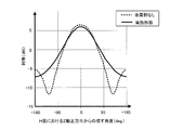
- FIG. 5 is a figure for demonstrating the effect of the vehicle-mounted antenna apparatus 10 of this embodiment, Comprising: It is a gain characteristic graph in H surface (YZ direction plane).
- the antenna gain in which the positive Z-axis direction in the H plane is 0 degrees and the negative direction in the Z axis is -180 degrees is shown. Since +90 degrees and -90 degrees are in the Y-axis direction, +90 degrees and -90 degrees are orthogonal to the line connecting the center of the radiation element 31 and the feeding point 31h in the plate surface direction of the radiation element 31 .
- the solid line indicates the characteristics of the on-vehicle antenna device 10 of the present embodiment, and the dotted line indicates the characteristics of a comparison configuration (conventional configuration) in which the metal portion 40 is omitted.
- the first metal wall portion 41 and the second metal wall are arranged outside the periphery of the radiation element 31 so that the wall intersects with a line (X-axis direction) connecting the center of the radiation element 31 and the feeding point 31h.
- the part 42 was provided.
- a metal wall may be provided so that the wall intersects the Y-axis direction. In that case, it is possible to improve the gain in the direction of the line connecting the center of the radiation element 31 and the feeding point 31h.
- FIG. 6A shows the H plane (YZ) when the wall heights of the first metal wall portion 41 and the second metal wall portion 42 (the projection length from the radiation element 31 (the length in the Z-axis direction)) are changed. Gain characteristic graph in the direction plane). Similarly to FIG. 5, the antenna gain in which the Z-axis positive direction in the H plane is 0 degrees and the Z-axis negative direction is ⁇ 180 degrees is shown. +90 degrees and -90 degrees are in the Y-axis direction.
- the dotted line indicates the wall height of 0 mm
- the solid line indicates the wall height of 3.5 mm corresponding to the present embodiment
- the broken line indicates the wall height of 6.0 mm.
- FIG. 6B is a view showing a cross section of the on-vehicle antenna device 10 equivalent to FIG. 3 in order to show the wall height.
- the metal wall portion of the metal portion 40 is a line connecting the center of the radiation element 31 and the feeding point 31h outside the periphery of the antenna main body 30, ie, outside the periphery of the radiation element 31.
- the radiation element 31 is provided on both sides of the radiation element 31 so as to intersect with the above.
- the on-vehicle antenna device 10 B may be configured to have only one side.
- FIG. 7 is a view showing an example of an internal configuration of the on-vehicle antenna device 10B in the case where one metal wall portion is provided on the outer side of the peripheral edge of the radiation element 31.
- FIG. 8 is a longitudinal cross-sectional view of the in-vehicle antenna device 10B including the first housing 11 taken along the line VIII-VIII in FIG. 7 and 8 show an example in which the first metal wall portion 41 is omitted and the second metal wall portion 42 is left, but the second metal wall portion 42 is omitted and the first metal is omitted.
- the wall 41 may be left.
- the vehicle-mounted antenna apparatus 10B shown to FIG. 7, FIG. 8 is shown as an example of the circularly-polarized-wave antenna of the 2nd modification mentioned later which provided two feeding points, one like the said embodiment. It may be a linearly polarized antenna with only the feed point 31h. As described above, even in the case where the metal wall portion is set to only one side, the gain in the direction intersecting the line connecting the center of the radiation element 31 and the feeding point 31h in the plate surface direction of the radiation element 31 Can be improved.
- the patch antenna 20 is a linearly polarized antenna, but as shown in FIGS. 7 and 8, a feeding point 31 j is provided in addition to the feeding point 31 h to provide a car antenna for a circularly polarized antenna. It can also be an apparatus 10B.
- FIG. 9 is a gain characteristic graph in the H plane (plane in the YZ direction) in the case of a circularly polarized antenna. Similarly to FIG. 5, the antenna gain in which the Z-axis positive direction in the H plane is 0 degrees and the Z-axis negative direction is ⁇ 180 degrees is shown. +90 degrees and -90 degrees are in the Y-axis direction. In the solid line in FIG.
- the metal wall portion is in a state in which the first metal wall portion 41 and the second metal wall portion 42 are present as in the above embodiment.
- the patch antenna is a circularly polarized antenna, in the plane direction of the radiating element 31, the direction orthogonal to the line connecting the center of the radiating element 31 and the feeding point 31h is obtained. It can be seen that the gain can be improved around ⁇ 90 degrees.
- FIG. 10 is a gain characteristic graph in the H plane (plane in the YZ direction) in the case of a quadrilateral configuration in which metal walls are provided on all four sides surrounding the radiating element 31.
- the antenna gain in which the Z-axis positive direction in the H plane is 0 degrees and the Z-axis negative direction is ⁇ 180 degrees is shown. +90 degrees and -90 degrees are in the Y-axis direction.
- the characteristics of the above-described embodiment the configuration in which the metal wall portions are provided on both sides across the radiation element 31
- the metal wall portion is omitted.
- the characteristic is shown by a dotted line
- the characteristic in the case of the configuration of a square box is indicated by a dashed dotted line.
- numerical values of gains at ⁇ 90 degrees are shown in the table.
- the center of the radiation element 31 and the feeding point in the plate surface direction of the radiation element 31 are compared with the comparison configuration (conventional configuration) in which the metal wall portion is omitted as compared with the comparison configuration (conventional configuration). It can be seen that the gain in the vicinity of ⁇ 90 degrees in the direction orthogonal to the line connecting 31h can be improved.
- FIG. 11 is a gain characteristic graph in the H plane (plane in the YZ direction) in the case of an L-shaped arrangement in which metal wall portions are provided in the L-shape on two adjacent sides among the four circumferences surrounding the radiation element 31.
- the antenna gain in which the Z-axis positive direction in the H plane is 0 degrees and the Z-axis negative direction is ⁇ 180 degrees is shown. +90 degrees and -90 degrees are in the Y-axis direction.
- the characteristics of the above-described embodiment the configuration in which the metal wall portions are provided on both sides across the radiation element 31
- the characteristic is indicated by a dotted line
- the characteristic in the case of the L-shaped arrangement is indicated by a two-dot chain line.
- numerical values of gains at ⁇ 90 degrees are shown in the table.
- the center of the radiating element 31 and the feed in the plate surface direction of the radiating element 31 are also supplied It can be seen that the gain in the vicinity of ⁇ 90 degrees in the direction orthogonal to the line connecting the point 31 h can be improved.
- the feeding system of the radiation element 31 is the back-axis coaxial feeding, as shown in FIG. 12, the microstrip line 34 is provided to configure the on-vehicle antenna device 10C in the form of coplanar feeding. It can also be done.
- the 1st metal wall part 41, the base part 49, and the 2nd metal wall part 42 are the integral metal parts 40 by making it the bending shape which bent the one end part and the other end part of a metal plate.
- the base portion 49 is omitted, and the first metal wall portion 41 and the second metal wall portion 42 are configured as independent metal parts, respectively. May be realized.
- the base plate 33 and the metal portion 40 are illustrated as being in the non-conductive state, but as shown in FIG. It may be realized.
- the ground plate 33 and the metal portion 40 may be integrated.
- the 1st metal wall part 41 and the 2nd metal wall part 42 were comprised so that it might become parallel or substantially parallel with Z-axis direction, the 1st metal wall part 41 and the 2nd metal wall part In 42, the wall surfaces do not necessarily have to be parallel.
- the tip is inclined so as to be close to the center side of the antenna main body 30, and as shown in FIG. 14, the tip is inclined to be away from the antenna main body 30. It may be a posture. If the gain in the direction intersecting the line connecting the center of the radiating element 31 and the feeding point 31h in the plate surface direction of the radiating element 31 is improved, what kind of first metal wall portion 41 and second metal wall portion 42 are It may be inclined at an angle.
Landscapes
- Engineering & Computer Science (AREA)
- Remote Sensing (AREA)
- Waveguide Aerials (AREA)
- Details Of Aerials (AREA)
- Support Of Aerials (AREA)
Abstract
板状の放射素子(31)の周縁の外側であって、壁面が放射素子(31)の中心と給電点とを結ぶ線と交差するように金属壁部(41,42)を設ける。また、金属壁部(41,42)を、放射素子(31)より放射方向に突出する形態に設定すると、より好適である。また、金属壁部(41,42)を、地板(33)と電気的に非導通状態に設置すると、より好適である。
Description
本発明は、パッチアンテナおよび車載用アンテナ装置に関する。
方形や円形の小面積の放射素子を有する平面アンテナとしてパッチアンテナが知られている。パッチアンテナの用途は広く、特許文献1には、衛星波の円偏波信号と地上波の直線偏波信号とを受信可能で、しかも配置した時の高さを低く抑えることができるパッチアンテナが開示されている。
従来のパッチアンテナは、板状の放射素子と、前記放射素子に平行に配置した板状の地板とを備えた構成が一般的であった。そのため、放射素子の板面に対する法線方向(放射素子の中心から見た仰角90度方向)の指向性が強い。しかし、Azimuth方向や方位角方向等と呼ばれる放射素子の中心から見た、放射素子の板面の延長方向である板面方向における各方位の指向性、すなわち、放射素子の板面方向における各方位の指向性は、放射素子の中心と給電点とを結ぶ線に平行な方向については利得が比較的に高いが、放射素子の中心と給電点とを結ぶ線に交差する方向については利得が比較的に低くなる。
本発明の第1の態様は、板状の放射素子と、前記放射素子の周縁の外側に、壁面が前記放射素子の中心と給電点とを結ぶ線と交差するように設けられた金属壁部と、を備えたパッチアンテナである。
第1の態様によれば、放射素子の周縁の外側に、壁面が放射素子の中心と給電点とを結ぶ線と交差するように金属壁部が設けられることとなる。この金属壁部によって電波の放射特性を変化させることができる。このため、放射素子の板面方向において、放射素子の中心と給電点とを結ぶ線に交差する方向の利得を向上させ得る技術が実現可能となる。
本発明の第2の態様は、前記金属壁部が、前記放射素子より放射方向に突出している、第1の態様に係るパッチアンテナである。
第2の態様によれば、金属壁部が、放射素子より放射方向に突出しているため、放射特性を大きく変化させることが可能となる。
本発明の第3の態様は、前記金属壁部が、地板と電気的に非導通状態に設置されている、第1又は第2の態様に係るパッチアンテナである。
第3の態様によれば、金属壁部が地板と電気的に非導通状態となる。このため、金属壁部と、アースとして機能する地板との相互作用を低減ないし抑制することができる。
本発明の第4の態様は、屈曲形状の金属によって基底部と前記金属壁部とが形成された金属部と、前記地板が前記基底部と間隔を空けて、前記金属部と電気的に非導通状態に設置され、かつ、前記放射素子および前記地板を有するアンテナ本体部と、を備えた第3の態様に係るパッチアンテナである。
本発明の第5の態様は、前記金属壁部が、前記放射素子を挟んだ両側に配置され、前記金属部が、中央部分を前記基底部、一端側および他端側を前記金属壁部とした屈曲形状を有する、第4の態様に係るパッチアンテナである。
第4又は第5の態様によれば、屈曲形状の金属によって金属壁部が形成可能となるため、金属壁部を簡単に製造することができる。また、金属部とアンテナ本体部との配置構成も比較的に簡単な構造とすることができる。このため、第1~第3の態様に係る作用効果を発揮するパッチアンテナを容易に製造可能になる。
本発明の第6の態様は、前記金属壁部が、金属薄膜として構成される、第1~第5の何れかの態様に係るパッチアンテナである。
第6の態様によれば、金属壁部の厚みを薄くすることができる。このため、パッチアンテナを小型化することができる。
本発明の第7の態様は、第1~第6の何れかの態様に係るパッチアンテナを具備する車載用アンテナ装置であって、車両の所定位置に所定向きに設置される筐体と、前記パッチアンテナが垂直偏波用となるように前記パッチアンテナを支持する支持部と、を具備する車載用アンテナ装置である。
第7の態様によれば、放射素子の板面方向において放射素子の中心と給電点とを結ぶ線に交差する方向の利得を向上させた垂直偏波用の車載用アンテナ装置を実現できる。
以下、本発明を適用した実施形態の一例を説明するが、本発明を適用可能な形態が以下の実施形態に限定されない。
また、本実施形態では方向を次のように定義する。まず、誘電体基板32を挟んで放射素子31と地板33(地導体板とも言う)とが積層された構造のパッチアンテナ20において(図3参照)、誘電体基板32から放射素子31に向かう方向を「放射方向」と呼称する。放射方向は、誘電体基板32から放射素子31に向かう方向と放射素子31から誘電体基板32に向かう方向との両方向ではなく、向きが決まった方向となる。また、左手系の直交3軸を定義する。直交3軸の座標原点は、放射素子31の板面中心とする。この直交3軸の方向が分かり易いように、直交3軸の各軸方向に平行な方向を示す参照方向を各図に付記した。参照方向としているのは、直交3軸の原点は、正しくは放射素子31の板面中心であるためである。あくまで方向の参照用として示している。
左手系の直交3軸において、放射素子31の板面に対する法線方向をZ軸方向とし、放射方向の向きをZ軸正方向とする。また、放射素子31の中心と給電点(芯線取付孔とも述べる)31hとを結ぶ線に沿った方向をX軸方向とし(図2参照)、放射素子31の中心から給電点31hに向かう方向をX軸正方向とする。Y軸方向並びにY軸正方向は、左手系の直交3軸であること、X軸正方向およびZ軸正方向が定義されることで自明となる。
別の表現で方向を定義すると、放射素子31の中心(直交3軸原点)から見て、放射素子31の板面に沿った方向(板面方向)を方位とした場合の仰角90度方向がZ軸正方向であり、放射素子31の中心から給電点31hに向かう方向がX軸正方向、Z軸正方向からZ軸負方向に俯瞰した場合のX軸正方向を12時方向とすると3時方向の方位がY軸正方向となる。なお、放射素子31の板面方向は、Azimuth方向や方位角方向等とも呼ばれる場合がある。
本明細書において、X軸方向と述べる場合は、X軸に平行な方向を意味し、X軸正方向およびX軸負方向の±両方向を含む意味とする。Y軸方向およびZ軸方向についても同様である。よって各軸方向は、各図に示した参照方向となる。
また、パッチアンテナ20において、放射素子31の電界面であるE面と、磁界面であるH面は、放射素子31の中心(直交3軸原点)から見て、X軸方向およびZ軸方向を含むXZ方向平面がE面、Y軸方向およびZ軸方向を含むYZ方向平面がH面となる。別の表現でE面及びH面を定義すると、放射素子31の板面に垂直な方向と、放射素子31の中心と給電点31hとを結ぶ線の方向とを含む平面がE面であり、このE面に垂直な平面であって且つ、放射素子31の板面に垂直な方向を含む平面がH面である。
図1は、本実施形態の車載用アンテナ装置10の構成例を示す斜視外観図と、使用例を示す概念図である。
車載用アンテナ装置10は、パッチアンテナを具備するV2X(Vehicle-to-everything)通信用の車載アンテナを備えるアンテナ装置であって、車両3の所定位置に所定向きに設置され、同軸ケーブル4を介して、V2Xコントローラ5に接続される。
車載用アンテナ装置10は、車内のフロントガラス上部(例えばルームミラー付近)に、放射方向が車両の前方を向くように設置される。ここで、前方とは、車両の前進方向の意味である。
車載用アンテナ装置10の設置位置と設置数は、想定する通信対象等の環境条件に応じて適宜変更できる。例えば、複数箇所設置するとしてもよい。設置場所も、例えば、ダッシュボードの上部でも良いし、バンパーや、ナンバープレートの取り付け部、Aピラー等のピラー部などでもよい。車内のリアガラスに、放射方向が車両の後方を向くように車載用アンテナ装置10を設置してもよい。ここで、後方とは、車両の後進方向の意味である。また、放射方向が車両の右方又は左方を向くように車載用アンテナ装置10を設置してもよい。ここで、右方とは、車両の前進方向に向かって右方の意味であり、左方とは、車両の前進方向に向かって左方の意味である。また、車載用アンテナ装置10が防水や防塵の性能条件が確保される構造を有する場合には車両の屋根等に設置してもよい。
本実施形態の車載用アンテナ装置10は、直方体状の外観を有し、放射方向に分割される第1筐体11と第2筐体12との分割構造のケースの中にパッチアンテナ20を内蔵する。そして、筐体側部に設けられた車体取付用の支持部13で車両3に装着されることで、パッチアンテナ20が垂直偏波用のアンテナとして好適に機能する。本実施形態では、支持部13を、車載用アンテナ装置10を設置するために用いるボルトやビスを挿通するためのボスとし、車両3から見て筐体の左右両側面(Y軸方向の両側面)それぞれに設ける構成としているが、支持部13の設定位置や設定数は適宜選択可能である。また、車載用アンテナ装置10を設置・固定する方法はボルトやビスを用いる方法に限らず他の方法でも良く、それに応じて支持部13も、適宜クリップ構造などその方法に適した構造を採用することができる。
支持部13は、第1筐体11および第2筐体12が車両3の所定位置に所定向きに設置されるように第1筐体11および第2筐体12を支持する。すなわち、第1筐体11および第2筐体12が車両3の所定位置に所定向きに設置されることで、パッチアンテナ20が垂直偏波用のアンテナとして機能するように、支持部13がパッチアンテナ20を支持する格好となる。
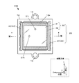
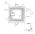
図2は、車載用アンテナ装置10の内部の構成例を説明するための図であって、第1筐体11を取り外して、第2筐体12の内部をZ軸正方向から見た図である。
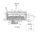
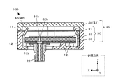
同様に、図3は、車載用アンテナ装置10の内部の構成例を説明するための図であり、第1筐体11を含めた車載用アンテナ装置10を図2のIII-III断面に沿って縦断した縦断面図である。
図4は、第1筐体11を含めた車載用アンテナ装置10の分解図であって、図3に示す車載用アンテナ装置10の分解図である。
同様に、図3は、車載用アンテナ装置10の内部の構成例を説明するための図であり、第1筐体11を含めた車載用アンテナ装置10を図2のIII-III断面に沿って縦断した縦断面図である。
図4は、第1筐体11を含めた車載用アンテナ装置10の分解図であって、図3に示す車載用アンテナ装置10の分解図である。
図3,図4に示すように、第1筐体11は凹部である上部収容空間11aを画成し、第2筐体12は凹部である下部収容空間12aを画成する。上部収容空間11aおよび下部収容空間12aは、第1筐体11および第2筐体12が組み付けられることで連続する1つの収容空間となる。パッチアンテナ20は、その収容空間の中、主に下部収容空間12aに収まるようにして設置される。
パッチアンテナ20は、図3,4に向かって上から順に、アンテナ本体部30と、金属部40と、を備える。
アンテナ本体部30は、図3,4に向かって上から順に、放射素子31と、誘電体基板32と、地板33と、を備える。アンテナ本体部30は、従来のパッチアンテナと同様に、プリント基板の製造方法を応用して作成することができる。
放射素子31は、Z軸正方向から見て矩形状の板状を有し、板面中心よりX軸正方向(パッチアンテナ20の直線偏波の偏波面に沿った方向)にずれた位置に同軸ケーブル4の芯線4aを挿通・固定するZ軸方向の貫通孔である芯線取付孔31hを備える。この芯線取付孔31hが給電点となる。従って、同じ符号を用いて適宜、給電点31hと述べる。なお、図3,4では、構造の理解が容易となるように、意図的に放射素子31や地板33のZ軸方向の厚さを大きく描いているが、実際は薄い板状、すなわち薄膜として形成してもよい。
誘電体基板32は、Z軸正方向から見ると放射素子31よりも広い面積を有する。放射素子31の芯線取付孔31hと連通する位置にZ軸方向に貫通する芯線挿通孔32hを有する。
地板33は、誘電体基板32の下面と同じ形状又は僅かに小さい形状を有し、放射素子31の芯線取付孔31hおよび誘電体基板32の芯線挿通孔32hと連通する芯線挿通孔33hを有する。地板33の下面には、この芯線挿通孔33hと同軸となるように、第2筐体12の底部に設けられた挿通孔12hを通じて基板用同軸コネクタ22が装着される。図3等において、芯線4aとの絶縁を確保するために、芯線挿通孔33hを大きめに図示している。しかし、地板33の芯線挿通孔33hの周囲に絶縁皮膜を施す等、地板33と芯線4aとの間の絶縁を確保している場合は、芯線挿通孔33hは芯線取付孔31hや芯線挿通孔32hと同径であってもよい。
金属部40は、X軸方向の両端部をZ軸正方向へ屈曲させた板金材である。具体的には、金属板の中央部を基底部49とし、一端側および他端側をそれぞれ90度又は略90度にZ軸正方向へ屈曲させることで、基底部49と第1金属壁部41と第2金属壁部42とを屈曲形状の金属で形成している。すなわち、第1金属壁部41と第2金属壁部42とは、壁面がH面に沿った向き(H面に平行又は略平行な向き)に設けられる。すなわち、第1金属壁部41と第2金属壁部42とは、壁面が放射素子31の中心と給電点31hとを結ぶ線(X軸方向)と直交するように設けられている。金属部40は、板金材では無く、例えば樹脂の表面に金属薄膜を形成したものでもよい。また、第2筐体12の内面(第1筐体11の内面も含む場合も有る)に金属薄膜を形成して金属部40としてもよい。このようにすることで、板金材が必要無くなるので、車載用アンテナ装置10を小型化することができる。これらの場合も、基底部49と第1金属壁部41と第2金属壁部42とは、屈曲形状の金属として形成される。また、基底部49を省略して、第1金属壁部41および第2金属壁部42を金属薄膜として構成してもよい。更に、第1金属壁部41および第2金属壁部42の一方のみを設ける場合には、その一方を金属薄膜として構成してもよい。
第1金属壁部41と第2金属壁部42とは、相互に平行又は略平行な平板部である。第1金属壁部41と第2金属壁部42のZ軸方向の長さは、それらのZ軸正方向側の端部(図3における上側の端部)が、アンテナ本体部30の上面(放射素子31の表面:Z軸正方向側端面)よりもZ軸正方向側に突出して位置するように設定される。
基底部49には、基板用同軸コネクタ22を挿通するコネクタ挿通孔49hと、第2筐体12の下部収容空間12aの底面よりZ軸正方向へ突出した突起部12t(図4参照)を挿通するための突起挿通孔49jと、が設けられている。
組立時、金属部40は、基底部49の突起挿通孔49jを第2筐体12の突起部12tを挿通するようにして位置合わせして、第2筐体12の底部に固定される。固定方法は、適宜選択可能であるが、例えば金属部40と第2筐体12の底部とを接着するとしてもよい。
突起部12tは、基底部49よりもZ軸正方向に突出し、その先端にアンテナ本体部30の下面(地板33の表面:Z軸負方向側端面)が当接され、アンテナ本体部30と突起部12tとが固定される。固定方法は、適宜選択可能であるが、例えばアンテナ本体部30と突起部12tとを接着するとしてもよい。この時、基底部49の上面(Z軸正方向側端面)から地板33の表面までの間隔は、2ミリメートル未満とすると好適である。また、アンテナ本体部30を固定する際には、アンテナ本体部30の外周部が金属部40に接触しないように間隔が設けられる。つまり、アンテナ本体部30は、基板用同軸コネクタ22ともども、金属部40とは電気的に非導通状態に設置される。
基底部49の上面と地板33の表面との間の間隔を含む、アンテナ本体部30と金属部40との間の間隔は、V2X通信の電波信号の伝播(導通)を妨げることのない一種のコンデンサとして機能する。そのため、この間隔は空気層すなわち空間としてもよいし、電気絶縁性材料である樹脂層としてもよい。樹脂層とするならば、樹脂を空間補充剤、兼、接合剤として利用することもできる。
アンテナ本体部30と金属部40とを非導通状態とすることで各種の利点が生じる。例えば、地板33と金属部40との相互作用を低減ないし抑制して、車載用アンテナ装置10を量産した際の特性や電気的安定性のバラツキを抑えることが可能になる。また、アンテナ本体部30を他のアンテナ装置に内蔵されるものと同一部品として量産効果を高めることが可能になる。
図5は、本実施形態の車載用アンテナ装置10の効果について説明するための図であって、H面(YZ方向平面)における利得特性グラフである。H面におけるZ軸正方向を0度とし、Z軸負方向を-180度としたアンテナ利得を示している。+90度および-90度がY軸方向となるため、+90度および-90度が、放射素子31の板面方向において、放射素子31の中心と給電点31hとを結ぶ線に直交する方向となる。また、実線が本実施形態の車載用アンテナ装置10の特性を示し、点線が金属部40を省略した比較用構成(従来構成)の特性を示している。
放射素子31の板面方向において、放射素子31の中心と給電点31hとを結ぶ線に直交する方向となる±90度付近に着目すると、利得が向上しており、第1金属壁部41および第2金属壁部42を設けることによる作用効果が表れている。パッチアンテナ20の特性として、放射素子31の周縁と地板33との間には電気力線が生じるが、E面に沿った方向の電気力線の方が、H面に沿った方向の電気力線よりも密度が高い。つまり、放射素子31の周縁のうち、第1金属壁部41に近い側の辺(図2に向かって放射素子31の四角形の右側の辺)と、第2金属壁部42に近い側の辺(図2に向かって放射素子31の四角形の左側の辺)とに、高密度の電気力線が生じる。この電気力線と、第1金属壁部41および第2金属壁部42との間で電磁作用が生じ、パッチアンテナ20の放射特性が変化する結果、利得が向上すると考えられる。
本実施形態では、放射素子31の周縁の外側に、壁面が放射素子31の中心と給電点31hとを結ぶ線(X軸方向)と交差するように第1金属壁部41および第2金属壁部42を設けた。この代わりに、壁面がY軸方向と交差するように金属壁部を設けてもよい。その場合には、放射素子31の中心と給電点31hとを結ぶ線の方向の利得向上を図ることが可能となる。
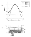
図6(A)は、第1金属壁部41と第2金属壁部42との壁高(放射素子31からの突出長(Z軸方向の長さ))を変更した場合のH面(YZ方向平面)における利得特性グラフである。図5と同様、H面におけるZ軸正方向を0度とし、Z軸負方向を-180度したアンテナ利得を示している。+90度および-90度がY軸方向となる。図6(A)において、点線が壁高0mm、実線が本実施形態に相当する壁高3.5mm、破線が壁高6.0mmの各特性を示している。図6(B)は、壁高を示すために、図3相当の車載用アンテナ装置10の断面を示した図である。
放射素子31の板面方向において、放射素子31の中心と給電点31hとを結ぶ線に直交する方向となる±90度付近に着目すると、壁高が放射素子31から突出していることで、利得特性が大きく改善されることが分かる。但し、壁高3.5mmと6.0mmとの間では利得特性に大きな差が見られないことが分かる。
〔変形例〕
以上、本発明を適用した実施形態の一例について説明したが、本発明を適用可能な形態は上記形態に限定されるものではなく適宜構成要素の追加・省略・変更を施すことができる。
以上、本発明を適用した実施形態の一例について説明したが、本発明を適用可能な形態は上記形態に限定されるものではなく適宜構成要素の追加・省略・変更を施すことができる。
[第1変形例]
例えば、上記実施形態では、金属部40の金属壁部を、アンテナ本体部30の周縁の外側、すなわち放射素子31の周縁の外側に、壁面が放射素子31の中心と給電点31hとを結ぶ線と交差するように、放射素子31を挟んだ両側に設ける構成とした。しかしこれを、図7、図8に示すように、何れか一方側のみとする構成の車載用アンテナ装置10Bとすることもできる。図7は、放射素子31の周縁の外側に1つの金属壁部を設けた場合の車載用アンテナ装置10Bの内部の構成例を示す図である。図8は、第1筐体11を含む、車載用アンテナ装置10Bを、図7のVIII-VIII断面に沿って縦断した場合の縦断面図である。図7、図8の例では、第1金属壁部41を省略して、第2金属壁部42を残した例を示しているが、第2金属壁部42を省略して、第1金属壁部41を残した構成でもよい。なお、図7、図8に示す車載用アンテナ装置10Bは、給電点を2つ設けた後述する第2変形例の円偏波アンテナの例として示しているが、上記実施形態のように1つの給電点31hのみとする直線偏波アンテナとしてもよい。このように、金属壁部を一方側のみとする構成とした場合であっても、放射素子31の板面方向において、放射素子31の中心と給電点31hとを結ぶ線に交差する方向の利得を向上させることができる。
例えば、上記実施形態では、金属部40の金属壁部を、アンテナ本体部30の周縁の外側、すなわち放射素子31の周縁の外側に、壁面が放射素子31の中心と給電点31hとを結ぶ線と交差するように、放射素子31を挟んだ両側に設ける構成とした。しかしこれを、図7、図8に示すように、何れか一方側のみとする構成の車載用アンテナ装置10Bとすることもできる。図7は、放射素子31の周縁の外側に1つの金属壁部を設けた場合の車載用アンテナ装置10Bの内部の構成例を示す図である。図8は、第1筐体11を含む、車載用アンテナ装置10Bを、図7のVIII-VIII断面に沿って縦断した場合の縦断面図である。図7、図8の例では、第1金属壁部41を省略して、第2金属壁部42を残した例を示しているが、第2金属壁部42を省略して、第1金属壁部41を残した構成でもよい。なお、図7、図8に示す車載用アンテナ装置10Bは、給電点を2つ設けた後述する第2変形例の円偏波アンテナの例として示しているが、上記実施形態のように1つの給電点31hのみとする直線偏波アンテナとしてもよい。このように、金属壁部を一方側のみとする構成とした場合であっても、放射素子31の板面方向において、放射素子31の中心と給電点31hとを結ぶ線に交差する方向の利得を向上させることができる。
[第2変形例]
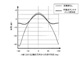
また、上記実施形態では、パッチアンテナ20を直線偏波アンテナとしたが、図7、図8に示すように、給電点31hの他に給電点31jを設けて、円偏波アンテナの車載用アンテナ装置10Bとすることもできる。図9は、円偏波アンテナとした場合のH面(YZ方向平面)における利得特性グラフである。図5と同様、H面におけるZ軸正方向を0度とし、Z軸負方向を-180度したアンテナ利得を示している。+90度および-90度がY軸方向となる。なお、図9の実線では、金属壁部は、上記実施形態同様、第1金属壁部41および第2金属壁部42がある状態である。図9に示すように、パッチアンテナを円偏波アンテナとした場合であっても、放射素子31の板面方向において、放射素子31の中心と給電点31hとを結ぶ線に直交する方向となる±90度付近において利得を向上させることができることが分かる。
また、上記実施形態では、パッチアンテナ20を直線偏波アンテナとしたが、図7、図8に示すように、給電点31hの他に給電点31jを設けて、円偏波アンテナの車載用アンテナ装置10Bとすることもできる。図9は、円偏波アンテナとした場合のH面(YZ方向平面)における利得特性グラフである。図5と同様、H面におけるZ軸正方向を0度とし、Z軸負方向を-180度したアンテナ利得を示している。+90度および-90度がY軸方向となる。なお、図9の実線では、金属壁部は、上記実施形態同様、第1金属壁部41および第2金属壁部42がある状態である。図9に示すように、パッチアンテナを円偏波アンテナとした場合であっても、放射素子31の板面方向において、放射素子31の中心と給電点31hとを結ぶ線に直交する方向となる±90度付近において利得を向上させることができることが分かる。
[第3変形例]
また、上記実施形態では、金属壁部を、放射素子31の周縁の外側に、放射素子31を囲む四囲のうちの、放射素子31を挟んだ両側に設ける構成とした。また、両側ではなく、一方側のみに金属壁部を設けてもよい変形例を第1変形例として説明した。しかし、放射素子31を囲む四囲全てに金属壁部を設けてもよいし、四囲のうちの隣り合う2辺にL字状に金属壁部を設けることとしてもよい。
また、上記実施形態では、金属壁部を、放射素子31の周縁の外側に、放射素子31を囲む四囲のうちの、放射素子31を挟んだ両側に設ける構成とした。また、両側ではなく、一方側のみに金属壁部を設けてもよい変形例を第1変形例として説明した。しかし、放射素子31を囲む四囲全てに金属壁部を設けてもよいし、四囲のうちの隣り合う2辺にL字状に金属壁部を設けることとしてもよい。
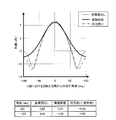
図10は、放射素子31を囲む四囲全てに金属壁部を設けた四方囲みの構成とした場合のH面(YZ方向平面)における利得特性グラフである。図5と同様、H面におけるZ軸正方向を0度とし、Z軸負方向を-180度したアンテナ利得を示している。+90度および-90度がY軸方向となる。比較のために、図10では、上述した実施形態(放射素子31を挟んだ両側に金属壁部を設けた構成)の特性を実線で、金属壁部を省略した比較用構成(従来構成)の特性を点線で、四方囲みの構成の場合の特性を一点鎖線で示している。また、±90度における利得の数値を表で示した。
図10に示すように、金属壁部を省略した比較用構成(従来構成)と比較して、四方囲みとした構成においても、放射素子31の板面方向において、放射素子31の中心と給電点31hとを結ぶ線に直交する方向となる±90度付近における利得を向上させることができることが分かる。
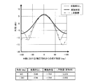
また、図11は、放射素子31を囲む四囲のうち、隣り合う2辺にL字状に金属壁部を設けたL字配置の場合のH面(YZ方向平面)における利得特性グラフである。図5と同様、H面におけるZ軸正方向を0度とし、Z軸負方向を-180度したアンテナ利得を示している。+90度および-90度がY軸方向となる。比較のために、図11では、上述した実施形態(放射素子31を挟んだ両側に金属壁部を設けた構成)の特性を実線で、金属壁部を省略した比較用構成(従来構成)の特性を点線で、L字配置の構成の場合の特性を二点鎖線で示している。また、±90度における利得の数値を表で示した。
図11に示すように、金属壁部を省略した比較用構成(従来構成)と比較して、L字配置とした構成においても、放射素子31の板面方向において、放射素子31の中心と給電点31hとを結ぶ線に直交する方向となる±90度付近における利得を向上させることができることが分かる。
[第4変形例]
また、上記実施形態では、放射素子31の給電方式を背面同軸給電としたが、図12に示すように、マイクロストリップ線路34を設けて共平面給電の形態とした車載用アンテナ装置10Cを構成することもできる。
また、上記実施形態では、放射素子31の給電方式を背面同軸給電としたが、図12に示すように、マイクロストリップ線路34を設けて共平面給電の形態とした車載用アンテナ装置10Cを構成することもできる。
[第5変形例]
また、上記実施形態では、金属板の一端部および他端部を屈曲させた屈曲形状とすることで、第1金属壁部41・基底部49・第2金属壁部42が一体の金属部40の構成を示したが、図13に示すように、基底部49を省略して、第1金属壁部41と第2金属壁部42とをそれぞれ独立した金属パーツとして構成した車載用アンテナ装置10Dを実現してもよい。
また、上記実施形態では、金属板の一端部および他端部を屈曲させた屈曲形状とすることで、第1金属壁部41・基底部49・第2金属壁部42が一体の金属部40の構成を示したが、図13に示すように、基底部49を省略して、第1金属壁部41と第2金属壁部42とをそれぞれ独立した金属パーツとして構成した車載用アンテナ装置10Dを実現してもよい。
[第6変形例]
また、上記実施形態では、地板33と金属部40とを非導通状態とする構成として例示したが、図14に示すように、接触させて電気的に導通させた構成の車載用アンテナ装置10Eを実現することとしてもよい。地板33と金属部40とを一体化した構成としてもよい。
また、上記実施形態では、地板33と金属部40とを非導通状態とする構成として例示したが、図14に示すように、接触させて電気的に導通させた構成の車載用アンテナ装置10Eを実現することとしてもよい。地板33と金属部40とを一体化した構成としてもよい。
[第7変形例]
また、上記実施形態では、第1金属壁部41と第2金属壁部42を、Z軸方向と平行又は略平行となるように構成したが、第1金属壁部41と第2金属壁部42とは、壁面が必ずしも平行である必要はない。例えば、図13に示すように、先端部をアンテナ本体部30の中央側に寄せるように傾斜させた姿勢や、図14に示すように、先端部がアンテナ本体部30から離れるように傾斜させた姿勢とすることとしてもよい。放射素子31の板面方向において、放射素子31の中心と給電点31hとを結ぶ線に交差する方向の利得が向上すれば、第1金属壁部41と第2金属壁部42はどのような角度で傾斜してもよい。
また、上記実施形態では、第1金属壁部41と第2金属壁部42を、Z軸方向と平行又は略平行となるように構成したが、第1金属壁部41と第2金属壁部42とは、壁面が必ずしも平行である必要はない。例えば、図13に示すように、先端部をアンテナ本体部30の中央側に寄せるように傾斜させた姿勢や、図14に示すように、先端部がアンテナ本体部30から離れるように傾斜させた姿勢とすることとしてもよい。放射素子31の板面方向において、放射素子31の中心と給電点31hとを結ぶ線に交差する方向の利得が向上すれば、第1金属壁部41と第2金属壁部42はどのような角度で傾斜してもよい。
10,10B,10C,10D,10E…車載用アンテナ装置
11…第1筐体
12…第2筐体
13…支持部
20…パッチアンテナ
22…基板用同軸コネクタ
30…アンテナ本体部
31…放射素子
31h…給電点(芯線取付孔)
32…誘電体基板
33…地板
40…金属部
41…第1金属壁部
42…第2金属壁部
49…基底部
11…第1筐体
12…第2筐体
13…支持部
20…パッチアンテナ
22…基板用同軸コネクタ
30…アンテナ本体部
31…放射素子
31h…給電点(芯線取付孔)
32…誘電体基板
33…地板
40…金属部
41…第1金属壁部
42…第2金属壁部
49…基底部
Claims (7)
- 板状の放射素子と、
前記放射素子の周縁の外側に、壁面が前記放射素子の中心と給電点とを結ぶ線と交差するように設けられた金属壁部と、
を備えたパッチアンテナ。 - 前記金属壁部は、前記放射素子より放射方向に突出している、
請求項1に記載のパッチアンテナ。 - 前記金属壁部は、地板と電気的に非導通状態に設置されている、
請求項1又は2に記載のパッチアンテナ。 - 屈曲形状の金属によって基底部と前記金属壁部とが形成された金属部と、
前記地板が前記基底部と間隔を空けて、前記金属部と電気的に非導通状態に設置され、かつ、前記放射素子および前記地板を有するアンテナ本体部と、
を備えた請求項3に記載のパッチアンテナ。 - 前記金属壁部は、前記放射素子を挟んだ両側に配置され、
前記金属部は、中央部分を前記基底部、一端側および他端側を前記金属壁部とした屈曲形状を有する、
請求項4に記載のパッチアンテナ。 - 前記金属壁部は、金属薄膜として構成される、
請求項1~5の何れか一項に記載のパッチアンテナ。 - 請求項1~6の何れか一項に記載のパッチアンテナを具備する車載用アンテナ装置であって、
車両の所定位置に所定向きに設置される筐体と、
前記筐体が前記所定位置に前記所定向きに設置されたときに、前記パッチアンテナが垂直偏波用となるように前記パッチアンテナを支持する支持部と、
を具備する車載用アンテナ装置。
Priority Applications (3)
| Application Number | Priority Date | Filing Date | Title |
|---|---|---|---|
| EP18866316.5A EP3696914A4 (en) | 2017-10-13 | 2018-08-01 | PATCH ANTENNA AND VEHICLE MOUNTED ANTENNA DEVICE |
| CN201880063746.3A CN111164831B (zh) | 2017-10-13 | 2018-08-01 | 贴片天线以及车载用天线装置 |
| US16/649,137 US11476565B2 (en) | 2017-10-13 | 2018-08-01 | Patch antenna and antenna device for vehicle |
Applications Claiming Priority (2)
| Application Number | Priority Date | Filing Date | Title |
|---|---|---|---|
| JP2017199095A JP6971119B2 (ja) | 2017-10-13 | 2017-10-13 | パッチアンテナおよび車載用アンテナ装置 |
| JP2017-199095 | 2017-10-13 |
Publications (1)
| Publication Number | Publication Date |
|---|---|
| WO2019073667A1 true WO2019073667A1 (ja) | 2019-04-18 |
Family
ID=66101432
Family Applications (1)
| Application Number | Title | Priority Date | Filing Date |
|---|---|---|---|
| PCT/JP2018/028892 Ceased WO2019073667A1 (ja) | 2017-10-13 | 2018-08-01 | パッチアンテナおよび車載用アンテナ装置 |
Country Status (5)
| Country | Link |
|---|---|
| US (1) | US11476565B2 (ja) |
| EP (1) | EP3696914A4 (ja) |
| JP (1) | JP6971119B2 (ja) |
| CN (1) | CN111164831B (ja) |
| WO (1) | WO2019073667A1 (ja) |
Cited By (2)
| Publication number | Priority date | Publication date | Assignee | Title |
|---|---|---|---|---|
| JP2024120888A (ja) * | 2023-02-24 | 2024-09-05 | 株式会社デンソー | アンテナ構造による通信および位置検索のためのmimoベースのシステムおよび方法 |
| WO2024195144A1 (ja) | 2023-03-22 | 2024-09-26 | 株式会社ヨコオ | アンテナ装置及びアンテナ装置の搭載方法 |
Families Citing this family (7)
| Publication number | Priority date | Publication date | Assignee | Title |
|---|---|---|---|---|
| CN112005435B (zh) | 2018-04-24 | 2022-08-05 | Agc株式会社 | 车辆用天线、附带车辆用天线的窗玻璃及天线系统 |
| JP7490070B2 (ja) * | 2020-09-28 | 2024-05-24 | 株式会社ヨコオ | パッチアンテナ |
| WO2023100908A1 (ja) | 2021-12-03 | 2023-06-08 | Agc株式会社 | アンテナ装置及び車両用アンテナ装置 |
| JP7845378B2 (ja) * | 2021-12-14 | 2026-04-14 | Agc株式会社 | 取付部材付きアンテナ装置及びアンテナ装置の取付構造 |
| US20250055181A1 (en) * | 2021-12-24 | 2025-02-13 | Yokowo Co., Ltd. | Patch antenna and antenna device |
| WO2023132715A1 (ko) * | 2022-01-07 | 2023-07-13 | 주식회사 케이엠더블유 | 안테나 보드 어셈블리 및 이를 포함하는 안테나 장치 |
| CN114678686A (zh) * | 2022-04-20 | 2022-06-28 | 泰州苏中天线集团有限公司 | 车联网v2x天线 |
Citations (7)
| Publication number | Priority date | Publication date | Assignee | Title |
|---|---|---|---|---|
| JPH03157005A (ja) * | 1989-08-21 | 1991-07-05 | Mitsubishi Electric Corp | マイクロストリップアンテナ |
| JP2002009537A (ja) * | 2000-06-22 | 2002-01-11 | Furukawa Electric Co Ltd:The | アンテナ |
| JP2003347838A (ja) | 2002-05-30 | 2003-12-05 | Yokowo Co Ltd | アンテナ装置 |
| JP2004320214A (ja) * | 2003-04-14 | 2004-11-11 | Mitsubishi Electric Corp | 狭域通信車載器 |
| JP2005294892A (ja) * | 2004-03-31 | 2005-10-20 | Maspro Denkoh Corp | アンテナ装置及びギャップフィラーシステム |
| WO2008136408A1 (ja) * | 2007-04-27 | 2008-11-13 | Nec Corporation | 金属壁付きパッチアンテナ |
| JP2012070156A (ja) * | 2010-09-22 | 2012-04-05 | Nippon Soken Inc | 複合アンテナ |
Family Cites Families (13)
| Publication number | Priority date | Publication date | Assignee | Title |
|---|---|---|---|---|
| JP3739230B2 (ja) * | 1999-04-26 | 2006-01-25 | 株式会社日立製作所 | 高周波通信装置 |
| BR0109773A (pt) * | 2000-04-04 | 2003-01-21 | Huber+Suhner Ag | Antena de comunicação de banda larga |
| JP3926089B2 (ja) * | 2000-09-26 | 2007-06-06 | 原田工業株式会社 | 車載用平面アンテナ装置 |
| JP4053486B2 (ja) * | 2003-09-29 | 2008-02-27 | 株式会社ヨコオ | マイクロストリップアンテナ |
| DE102006038528B3 (de) * | 2006-08-17 | 2007-11-22 | Kathrein-Werke Kg | Abstimmbare Antenne planarer Bauart |
| CN101558531B (zh) * | 2006-12-15 | 2013-02-27 | 株式会社村田制作所 | 天线及具备该天线的通信装置 |
| CN101990725B (zh) * | 2008-02-04 | 2014-08-20 | Agc汽车美洲研发公司 | 多元件空腔耦合天线 |
| US7936306B2 (en) * | 2008-09-23 | 2011-05-03 | Kathrein-Werke Kg | Multilayer antenna arrangement |
| JP4976533B2 (ja) | 2010-09-10 | 2012-07-18 | Dxアンテナ株式会社 | アンテナ |
| EP2477275A1 (en) * | 2011-01-12 | 2012-07-18 | Alcatel Lucent | Patch antenna |
| CN202930564U (zh) * | 2012-11-29 | 2013-05-08 | 深圳市鼎耀科技有限公司 | 一种多频卫星导航天线 |
| EP3176871B1 (en) * | 2015-02-05 | 2019-05-01 | Fujikura Ltd. | Vehicle-mounted antenna device |
| US10347991B2 (en) * | 2016-05-08 | 2019-07-09 | Tubis Technology, Inc. | Orthogonally polarized dual frequency co-axially stacked phased-array patch antenna apparatus and article of manufacture |
-
2017
- 2017-10-13 JP JP2017199095A patent/JP6971119B2/ja active Active
-
2018
- 2018-08-01 US US16/649,137 patent/US11476565B2/en active Active
- 2018-08-01 CN CN201880063746.3A patent/CN111164831B/zh active Active
- 2018-08-01 WO PCT/JP2018/028892 patent/WO2019073667A1/ja not_active Ceased
- 2018-08-01 EP EP18866316.5A patent/EP3696914A4/en not_active Withdrawn
Patent Citations (7)
| Publication number | Priority date | Publication date | Assignee | Title |
|---|---|---|---|---|
| JPH03157005A (ja) * | 1989-08-21 | 1991-07-05 | Mitsubishi Electric Corp | マイクロストリップアンテナ |
| JP2002009537A (ja) * | 2000-06-22 | 2002-01-11 | Furukawa Electric Co Ltd:The | アンテナ |
| JP2003347838A (ja) | 2002-05-30 | 2003-12-05 | Yokowo Co Ltd | アンテナ装置 |
| JP2004320214A (ja) * | 2003-04-14 | 2004-11-11 | Mitsubishi Electric Corp | 狭域通信車載器 |
| JP2005294892A (ja) * | 2004-03-31 | 2005-10-20 | Maspro Denkoh Corp | アンテナ装置及びギャップフィラーシステム |
| WO2008136408A1 (ja) * | 2007-04-27 | 2008-11-13 | Nec Corporation | 金属壁付きパッチアンテナ |
| JP2012070156A (ja) * | 2010-09-22 | 2012-04-05 | Nippon Soken Inc | 複合アンテナ |
Cited By (3)
| Publication number | Priority date | Publication date | Assignee | Title |
|---|---|---|---|---|
| JP2024120888A (ja) * | 2023-02-24 | 2024-09-05 | 株式会社デンソー | アンテナ構造による通信および位置検索のためのmimoベースのシステムおよび方法 |
| WO2024195144A1 (ja) | 2023-03-22 | 2024-09-26 | 株式会社ヨコオ | アンテナ装置及びアンテナ装置の搭載方法 |
| EP4685997A1 (en) | 2023-03-22 | 2026-01-28 | Yokowo Co., Ltd | Antenna device and installation method for antenna device |
Also Published As
| Publication number | Publication date |
|---|---|
| JP6971119B2 (ja) | 2021-11-24 |
| US20200295444A1 (en) | 2020-09-17 |
| CN111164831A (zh) | 2020-05-15 |
| EP3696914A1 (en) | 2020-08-19 |
| EP3696914A4 (en) | 2021-06-30 |
| JP2019075644A (ja) | 2019-05-16 |
| US11476565B2 (en) | 2022-10-18 |
| CN111164831B (zh) | 2023-01-10 |
Similar Documents
| Publication | Publication Date | Title |
|---|---|---|
| WO2019073667A1 (ja) | パッチアンテナおよび車載用アンテナ装置 | |
| JP7634032B2 (ja) | アンテナ装置 | |
| EP2538489B1 (en) | Composite resonating antenna structure | |
| JP7550328B2 (ja) | パッチアンテナ | |
| JP2018074263A (ja) | 車両用アンテナ及びアンテナ付き窓ガラス | |
| JP7793312B2 (ja) | アンテナ装置 | |
| JP7782156B2 (ja) | 車両用無線装置 | |
| WO2023127835A1 (ja) | パッチアンテナ及びアンテナ装置 | |
| CN218160806U (zh) | 贴片天线以及天线装置 | |
| WO2024116430A1 (ja) | アンテナ装置 | |
| US12620713B2 (en) | Patch antenna and antenna device | |
| US20240322435A1 (en) | Antenna device and vehicle antenna device | |
| US20260039013A1 (en) | Antenna device | |
| JP3804924B2 (ja) | 平面アンテナ | |
| WO2024176729A1 (ja) | アンテナ及びアンテナの製造方法 | |
| WO2024034680A1 (ja) | パッチアンテナ | |
| JP2007336279A (ja) | アンテナ | |
| WO2025191968A1 (ja) | アンテナ及びアンテナ装置 | |
| WO2021153132A1 (ja) | アンテナ装置 | |
| JP2008182432A (ja) | 車載用無線通信装置 | |
| JP2009032622A (ja) | 接点装置及びガラスアンテナ装置 |
Legal Events
| Date | Code | Title | Description |
|---|---|---|---|
| 121 | Ep: the epo has been informed by wipo that ep was designated in this application |
Ref document number: 18866316 Country of ref document: EP Kind code of ref document: A1 |
|
| NENP | Non-entry into the national phase |
Ref country code: DE |
|
| ENP | Entry into the national phase |
Ref document number: 2018866316 Country of ref document: EP Effective date: 20200513 |