WO2019073697A1 - スピーカユニット - Google Patents
スピーカユニット Download PDFInfo
- Publication number
- WO2019073697A1 WO2019073697A1 PCT/JP2018/030983 JP2018030983W WO2019073697A1 WO 2019073697 A1 WO2019073697 A1 WO 2019073697A1 JP 2018030983 W JP2018030983 W JP 2018030983W WO 2019073697 A1 WO2019073697 A1 WO 2019073697A1
- Authority
- WO
- WIPO (PCT)
- Prior art keywords
- diaphragm
- voice coil
- inner peripheral
- speaker unit
- outer peripheral
- Prior art date
- Legal status (The legal status is an assumption and is not a legal conclusion. Google has not performed a legal analysis and makes no representation as to the accuracy of the status listed.)
- Ceased
Links
Images


Classifications
-
- H—ELECTRICITY
- H04—ELECTRIC COMMUNICATION TECHNIQUE
- H04R—LOUDSPEAKERS, MICROPHONES, GRAMOPHONE PICK-UPS OR LIKE ACOUSTIC ELECTROMECHANICAL TRANSDUCERS; ELECTRIC HEARING AIDS; PUBLIC ADDRESS SYSTEMS
- H04R9/00—Transducers of moving-coil, moving-strip, or moving-wire type
- H04R9/02—Details
- H04R9/025—Magnetic circuit
-
- H—ELECTRICITY
- H04—ELECTRIC COMMUNICATION TECHNIQUE
- H04R—LOUDSPEAKERS, MICROPHONES, GRAMOPHONE PICK-UPS OR LIKE ACOUSTIC ELECTROMECHANICAL TRANSDUCERS; ELECTRIC HEARING AIDS; PUBLIC ADDRESS SYSTEMS
- H04R7/00—Diaphragms for electromechanical transducers; Cones
- H04R7/02—Diaphragms for electromechanical transducers; Cones characterised by the construction
- H04R7/12—Non-planar diaphragms or cones
-
- H—ELECTRICITY
- H04—ELECTRIC COMMUNICATION TECHNIQUE
- H04R—LOUDSPEAKERS, MICROPHONES, GRAMOPHONE PICK-UPS OR LIKE ACOUSTIC ELECTROMECHANICAL TRANSDUCERS; ELECTRIC HEARING AIDS; PUBLIC ADDRESS SYSTEMS
- H04R7/00—Diaphragms for electromechanical transducers; Cones
- H04R7/02—Diaphragms for electromechanical transducers; Cones characterised by the construction
-
- H—ELECTRICITY
- H04—ELECTRIC COMMUNICATION TECHNIQUE
- H04R—LOUDSPEAKERS, MICROPHONES, GRAMOPHONE PICK-UPS OR LIKE ACOUSTIC ELECTROMECHANICAL TRANSDUCERS; ELECTRIC HEARING AIDS; PUBLIC ADDRESS SYSTEMS
- H04R9/00—Transducers of moving-coil, moving-strip, or moving-wire type
- H04R9/02—Details
-
- H—ELECTRICITY
- H04—ELECTRIC COMMUNICATION TECHNIQUE
- H04R—LOUDSPEAKERS, MICROPHONES, GRAMOPHONE PICK-UPS OR LIKE ACOUSTIC ELECTROMECHANICAL TRANSDUCERS; ELECTRIC HEARING AIDS; PUBLIC ADDRESS SYSTEMS
- H04R9/00—Transducers of moving-coil, moving-strip, or moving-wire type
- H04R9/02—Details
- H04R9/04—Construction, mounting, or centering of coil
Definitions
- the present invention relates to a loudspeaker unit, and more particularly to a thin loudspeaker unit.
- FIG. 10 to FIG. 10 is a cross-sectional view taken along the line B--O--C of FIG. 11, and FIG. 11 is a top view excluding the dust cap of FIG.
- the magnetic circuit 8 is stacked on the bottomed cylindrical yoke 4 whose one end face is an open surface, the disk-shaped magnet 7 provided on the inner bottom surface of the yoke 4, and the magnet 7. And a disc-shaped center pole 6 arranged to The cylindrical portion of the yoke 4 is provided with six slits 5 extending from the end on the open surface side toward the bottom at a pitch of 60 degrees along the circumferential direction.
- a gap is formed between the outer peripheral surface of the magnet 7, the outer peripheral surface of the center pole 6, and the inner peripheral surface of the cylindrical portion of the yoke 4, and the outer peripheral surface of the center pole 6 and the inner peripheral surface of the yoke 4 The gap between them is a magnetic gap.
- the voice coil 3 disposed in the magnetic gap is composed of a cylindrical bobbin 1 and a coil 2 wound around the circumferential surface of the bobbin 1.
- the double ring 12 connects the outer ring 10 opposed to the outer peripheral surface of the yoke 4 via the space, the inner ring 9 connected to the bobbin 1 of the voice coil 3, the outer ring 10, and the six inner rings 9 connected. It consists of a joint 11 and the like.
- the joint 11 is disposed corresponding to the slit 5 of the magnetic circuit 8.
- the voice coil 3 and the double ring 12 are integrated.
- the inner peripheral portion of the diaphragm 13 is connected to the lower portion of the outer ring 10 of the double ring 12.
- the outer peripheral portion of the diaphragm 13 is attached to the frame 16 via the edge 15.
- a dust cap 17 covering the bobbin 1 and the double ring 12 is provided at the central portion of the diaphragm 13.
- a magnetic field is generated in the magnetic gap of the magnetic circuit 8.
- a driving force (propulsive force) is generated in the voice coil 3 due to Fleming's left-hand rule, whereby the diaphragm 13 vibrates. Sound is emitted.
- the inner peripheral surface of the diaphragm 13 is connected to the lower part of the outer ring 10 of the double ring 12, whereby the speaker unit can be made thinner.
- the speaker unit having the configuration shown in FIG. 10 to FIG. 11 can be made thinner, the double ring 12 is necessary, and there are the following problems.
- (3) The portion driven and vibrated by the voice coil 3 is composed of two members of the diaphragm 13 and the double ring 12 and the mass is heavy, so a strong magnetic circuit 8 is required and the cost is increased.
- the mass of the vibrating part becomes heavy, the response of the diaphragm 13 becomes worse and the sound quality becomes worse.
- the present invention has been made in view of the above-mentioned problems, and an object thereof is to provide a speaker unit which can be made low in cost, good in sound quality, and made thin.
- the speaker unit of the invention according to claim 1 which solves the problem,
- a magnetic circuit having an outer peripheral cylindrical portion, wherein an annular space serving as a magnetic gap is formed inside the outer peripheral cylindrical portion;
- a voice coil disposed in the magnetic gap;
- a diaphragm having a central hole penetrating at the center, an outer peripheral portion side supported by the frame, and an inner peripheral surface of the inner peripheral portion connected to the voice coil
- the outer peripheral cylindrical portion of the magnetic circuit has a standing wall portion formed along the vibration direction of the diaphragm, and a slit.
- the inner circumferential portion of the diaphragm has a standing wall insertion portion through which the standing wall portion is inserted, and an insertion portion through which the slit is inserted.
- the diaphragm has a standing wall insertion portion through which the standing wall portion of the outer peripheral cylindrical portion of the magnetic circuit is inserted and an insertion portion inserted through the slit of the outer peripheral cylindrical portion.
- the diaphragm and the voice coil can be connected. Therefore, the speaker unit can be thinned without lowering the height in the vibration direction of the diaphragm.
- the height difference (full height) of the diaphragm can be sufficiently secured, it is possible to suppress the reduction of the rigidity of the entire diaphragm.
- the speaker unit By connecting the inner peripheral surface of the center hole of the diaphragm to the lower portion of the voice coil, the speaker unit can be reliably thinned without lowering the height (full height) in the vibration direction of the diaphragm. .
- the double ring conventionally required for thinning the speaker unit becomes unnecessary, the number of parts can be reduced, and the cost can be reduced.
- the portion driven and vibrated by the voice coil is only the diaphragm and the mass is reduced, so that a strong magnetic circuit is not required and the cost can be reduced. (5) Since the mass of the vibrating part is reduced, the response of the diaphragm is good and the sound quality is improved.
- FIG. 6 is a cross-sectional view taken along line VI-VI of FIG. 2;
- FIG. 7 is a cross-sectional view taken along line VII-VII of FIG. 2;
- FIG. 12 is a cross-sectional view taken along line B-O-C in FIG. It is the top view except the dust cap of FIG.
- FIG. 1 is an exploded perspective view for explaining a first embodiment of the speaker unit according to the present invention
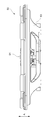
- FIG. 2 is a front view when FIG. 1 is assembled
- FIG. 3 is a back view of
- FIG. 5 is a V direction arrow view of FIG. 2
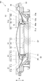
- FIG. 6 is a sectional view taken along the line VI-VI of FIG. 2
- FIG. 7 is a sectional view taken along the line VII-VII of FIG.
- the outer peripheral portion 51 b of the diaphragm 51 is attached to the frame 53 via the edge 55.
- the diaphragm 51 has a shape in which the center is recessed from the outer peripheral portion 51b to the inner peripheral portion 51c, and a circular central hole 51a penetrating in the thickness direction of the diaphragm 51 is formed at the center (inner peripheral portion 51c).
- the frame 53 has a shape in which the center is indented in the same direction as the diaphragm 51, has a bottom 53a at the center, and a hole 53b penetrating in the thickness direction is formed in the bottom 53a.
- a magnetic circuit 61 is provided at the bottom 53 a of the frame 53.
- the magnetic circuit 61 includes a yoke 63, a magnet 65, and a pole piece 66.
- the yoke 63 is made of a hard magnetic material and has a cylindrical shape with a bottom, one surface of which is an open surface, and the base 67 attached to the hole 53 b of the bottom 53 a of the frame 53 and the vibration of the diaphragm 51 from the periphery of the base 67
- a cylindrical portion 69 extending in the direction away from the bottom 53a of the frame 53 along the direction (FIGS. 1 and 4 in the direction of the arrow A in FIG. 4) and serving as the outer peripheral cylindrical portion of the magnetic circuit 61; Have (see Figure 6). That is, the cylindrical portion 69 is the outer peripheral cylindrical portion in the present invention.
- the cylindrical portion 69 is formed with a plurality of upright wall portions 69c and slits 69a extending toward the base 67 along the vibration direction (arrow A direction) of the diaphragm 51 from the end on the open surface side.
- the cylindrical portion 69 is composed of four slits 69 a and four standing wall portions 69 c divided by the four slits 69 a.
- the base portion 67 is formed with four attaching portions 67a extending outward, corresponding to the slits 69a. Positioning of the magnetic circuit 61 with respect to the frame 53 is achieved by fitting the four attachment portions 67 a into the four attachment recesses 53 c formed on the periphery of the hole 53 b of the frame 53.
- the magnet 65 is formed in a disk shape and mounted on the base 67 of the yoke 63.
- the magnetization direction of the magnet 65 is the vibration direction (arrow A direction) of the diaphragm 51.
- a disc-shaped pole piece 66 made of a hardly magnetic material is placed on the magnet 65. Therefore, an annular space is formed between the inner circumferential surface of the cylindrical portion 69 of the yoke 63 and the outer circumferential surface of the pole piece 66.
- This annular space is a magnetic gap G in which a substantially uniform magnetic field is generated in the circumferential direction. It has become.
- the inner circumferential portion 51c of the diaphragm 51 includes four insertion holes 57 through which the vertical wall 69c of the yoke 63 of the magnetic circuit 61 is inserted, and four insertion portions 59 through which the slits 69a of the yoke 63 of the magnetic circuit 61 are inserted.
- the insertion hole 57 penetrates in the vibration direction (thickness direction) of the diaphragm 51. This insertion hole 57 is used as a standing wall insertion portion in the present invention.
- the inner peripheral portion 51 c of the diaphragm 51 is a ring-shaped inner annular portion 591 formed on the inner peripheral side of the diaphragm 51 than the respective insertion holes 57, and the outer peripheral side of the diaphragm 51 than the respective insertion holes 57. And a ring-shaped outer annular portion 592 formed thereon. Therefore, each insertion hole 57 is formed between the inner annular portion 591 and the outer annular portion 592.
- the central hole 51a of the diaphragm 51 is formed by the inner peripheral surface of the inner annular portion 591 (the inner peripheral surface of the inner peripheral portion 51c). The inner circumferential surface of the inner annular portion 591 is connected to the voice coil 85.
- each insertion portion 59 may be connected to the voice coil 85 without forming the inner annular portion 591.
- Voice coil 85 includes cylindrical bobbin 81 disposed between the inner peripheral surface of cylindrical portion 69 (vertical wall portion 69 c) of yoke 63 and the outer peripheral surface of magnet 65 and pole piece 66, and the outer peripheral surface of bobbin 81. And a coil 83 wound around the. Then, the bobbin 81 and the inner circumferential surface of the central hole 51a of the diaphragm 51 (the inner circumferential surface of the inner circumferential portion 51c of the diaphragm 51) are connected so that the coil 83 is positioned at the magnetic gap G of the magnetic circuit 61. ing.
- the inner peripheral surface (inner peripheral surface of the inner annular portion 591) of the inner peripheral portion 51c of the diaphragm 51 and the voice coil 85 are connected via the slits 69a of the yoke 63 of the magnetic circuit 61.
- the inner peripheral surface of the central hole 51 a of the diaphragm 51 (the inner peripheral surface of the inner peripheral portion 51 c of the diaphragm 51) is connected to the lower portion of the bobbin 81.
- the outer peripheral surface of the bobbin 81 disposed on the base 67 side of the yoke 63 that is, the inner peripheral surface of the central hole 51a of the diaphragm 51 (diaphragm)
- the inner circumferential surface 51 of the inner circumferential portion 51 c is connected.
- the outer peripheral portion 51b and the inner peripheral portion 51c are integrally formed. Further, the thickness of the inner peripheral portion 51c of the diaphragm 51 is formed larger (thicker) than the thickness of the outer peripheral portion 51b. Furthermore, the inner circumferential portion 51 c of the diaphragm 51 is formed in a shape that gradually reduces in diameter toward the lower side in the vibration direction (arrow A direction), and in the inner circumferential portion 51 c of the diaphragm 51 from the outer annular portion 592 The inner annular portion 591 is disposed below the vibration direction (arrow A direction). Further, as shown in FIG.
- the thickness (t1) of the bonding surface between the diaphragm 51 and the bobbin 81 is larger than the thickness (t2) of the outer peripheral portion 51b ((2) Thick) is formed.
- the dust cap 91 which constitutes a part of the diaphragm 51 is used to prevent the infiltration of dust and the like from the center hole 51 a of the diaphragm 51.
- the dust cap 91 is connected to the dome-shaped dome portion 91 c covering the opening of the bobbin 81, the diaphragm connection portion 91 a connected to the diaphragm 51, and the voice coil 85 as shown in FIGS. 6 and 7.
- a voice coil connection portion 91b is formed on the outermost side of the dust cap 91 and covers the upper side of the inner peripheral portion 51 c of the diaphragm 51.
- the voice coil connection portion 91 b is formed on the inner peripheral side of the diaphragm connection portion 91 a.
- the voice coil connection portion 91 b of the dust cap 91 is connected to the outer peripheral surface (upper part of the bobbin 81) of the bobbin 81 above the coil 83 of the voice coil 85.
- the outer peripheral edge of the diaphragm connecting portion 91a of the dust cap 91 is connected to the outer peripheral side of the inner peripheral portion 51c located near the boundary between the inner peripheral portion 51c and the outer peripheral portion 51b of the diaphragm 51.
- the inner peripheral surface of the center hole 51 a of the diaphragm 51 (the inner peripheral surface of the inner annular portion 591) is connected to the outer peripheral surface of the lower bobbin 81 of the coil 83.
- the inner peripheral surface of the inner peripheral portion 51c of the diaphragm 51 is connected to the lower portion of the bobbin 81, and the outer peripheral side of the inner peripheral portion 51c is connected to the outer peripheral edge of the diaphragm connecting portion 91a of the dust cap 91.
- a voice coil connection portion 91 b 91 is connected to the top of the bobbin 81.
- the upper side of the inner peripheral portion 51c of the diaphragm 51 is covered with the diaphragm connection portion 91a, so that the inner peripheral portion 51c of the diaphragm 51 and the diaphragm connection of the dust cap 91 are connected to the inside of the diaphragm connection portion 91a.
- An internal space surrounded by the portion 91 a and the voice coil 85 is formed.
- a terminal 52 is provided on the frame 53, and the terminal 52 and the coil 83 of the voice coil 85 are electrically connected by a tinsel wire (lead wire) not shown.
- the electrical signal input to the terminal 52 flows to the coil 83 of the voice coil 85 via the tinsel wire. Since the coil 83 is disposed in the magnetic field generated by the magnetic circuit 61, the diaphragm 51 vibrates in the direction of arrow A by the driving force generated in the coil 83 (voice coil 85), and a sound is emitted.
- the diaphragm 51 has an insertion hole 57 through which the vertical wall 69 c of the cylindrical portion 69 of the magnetic circuit 61 is inserted, and an insertion portion 59 which is inserted through the slit 69 a of the cylindrical portion 69.
- the bonding surface of the diaphragm 51 and the voice coil 85 can be disposed below the tip (the tip of the yoke 63). Therefore, the speaker unit 50 can be thinned without lowering the height of the diaphragm 51 in the vibration direction.
- the difference in height of the cone shape of the diaphragm 51 can be sufficiently secured, it is possible to suppress the reduction of the rigidity of the diaphragm 51 as a whole.
- the speaker unit 50 can be reliably thinned without lowering the height of the plate 51 in the vibration direction.
- the dust cap 91 includes the diaphragm connection portion 91 a connected to the diaphragm 51 and the voice coil connection portion 91 b connected to the voice coil 85, thereby increasing the rigidity of the diaphragm 51. Therefore, the speed at which the sound propagates in the diaphragm 51 is increased, the reaction (transjet characteristics) is good, and a precise and delicate sound can be reproduced.
- the rigidity of the diaphragm 51 can be increased by integrally molding the inner peripheral portion 51 c and the outer peripheral portion 51 b of the diaphragm 51.
- the thickness (t1) in the vibration direction of the bonding surface of the inner peripheral portion 51c of the diaphragm 51 and the bobbin 81 is larger than the thickness (t2) of the outer peripheral portion 51b of the diaphragm 51, so that the bobbin 81 and the diaphragm
- the bonding area with 51 can be increased, and the durability of the speaker unit 50 can be improved.
- the speaker unit 50 configured to have no damper for supporting the voice coil, as shown in FIGS. 8 and 9, the speaker unit is further provided with a damper for supporting the voice coil. It is good.
- FIG. 8 is a half sectional view of a speaker unit 150 according to a second embodiment of the present invention
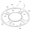
- FIG. 9 is a perspective view of the damper 201 of FIG.
- the outer peripheral portion 151 b of the diaphragm 151 is attached to the frame 153 via the edge 155.
- the diaphragm 151 has a shape in which the center is recessed from the outer peripheral portion 151b to the inner peripheral portion 151c, and a circular central hole 151a penetrating in the thickness direction of the diaphragm 151 is formed at the center (inner peripheral portion 151c).
- the frame 153 has a center indented in the same direction as the diaphragm 151, has a bottom portion 153a at the center, and a hole 153b penetrating in the thickness direction is formed in the bottom portion 153a.
- a magnetic circuit 161 is provided at the bottom 153 a of the frame 153.
- the magnetic circuit 161 includes a yoke 163, a magnet 165, and a pole piece 166.
- the yoke 163 is made of a hard magnetic material and has a cylindrical shape with a bottom, one surface of which is an open surface, and the base 167 attached to the hole 153 b of the bottom 153 a of the frame 153 and the vibration of the diaphragm 151 from the periphery of the base 167
- a cylindrical portion 169 extends in the direction away from the bottom portion 153 a of the frame 153 along the direction (arrow A ′ direction in FIG. 8), and functions as an outer peripheral cylindrical portion of the magnetic circuit 161. That is, the cylindrical portion 169 is the outer peripheral cylindrical portion in the present invention.
- the cylindrical portion 169 is formed with a plurality of upright wall portions 169c and slits 169a extending toward the base portion 167 along the vibration direction (arrow A 'direction) of the diaphragm 151 from the end on the open surface side.
- the four slits 169 a in the present embodiment are provided at a pitch of 90 ° along the circumferential direction of the cylindrical portion 169. Therefore, the cylindrical portion 169 is composed of four slits 169 a and four upright wall portions 169 c divided by the four slits 169 a.
- the magnet 165 is formed in a disk shape and mounted on the base 167 of the yoke 163.
- the magnetization direction of the magnet 165 is the vibration direction (arrow A ′ direction) of the diaphragm 151.
- a disc-shaped pole piece 166 made of a hardly magnetic material is mounted on the magnet 165. Therefore, an annular space is formed between the inner circumferential surface of the cylindrical portion 169 of the yoke 163 and the outer circumferential surface of the pole piece 166, and the annular space is a magnetic gap G in which a substantially uniform magnetic field is generated in the circumferential direction. It is'.
- the diaphragm 151 has the same shape as the diaphragm 51 of the first embodiment, and four insertion holes (vertical wall insertion portions through which the vertical wall portion 169c of the yoke 163 of the magnetic circuit 161 is inserted through the inner peripheral portion 151c of the horizontal plate 151). ) And four insertion parts 159 which are inserted into the slits 169a of the yoke 163 of the magnetic circuit 161 are alternately formed along the circumferential direction.
- the insertion hole 157 penetrates in the vibration direction (thickness direction) of the diaphragm 151.
- Voice coil 185 has a cylindrical bobbin 181 disposed between the inner peripheral surface of cylindrical portion 169 (vertical wall portion 169c) of yoke 163 and the outer peripheral surface of magnet 165 and pole piece 166, and the outer peripheral surface of bobbin 181 And a coil 183 wound around the. Then, the bobbin 181 is connected to the inner circumferential surface of the central hole 151a of the diaphragm 151 (the inner circumferential surface of the inner circumferential portion 151c of the diaphragm 151) so that the coil 183 is positioned at the magnetic gap G 'of the magnetic circuit 161. It is done. That is, the inner peripheral surface of the inner peripheral portion 151 c of the diaphragm 151 and the voice coil 185 are connected via the slit 169 a of the yoke 163 of the magnetic circuit 161.
- the direction in which the diaphragm 151 moves away from the magnetic circuit 161 (the base 167 of the yoke 163) is upward, and the direction in which the diaphragm 151 approaches the magnetic circuit 161 is downward.
- the inner peripheral surface of the central hole 151a of the diaphragm 151 (the inner peripheral surface of the inner peripheral portion 151c of the diaphragm 151) is connected to the lower portion of the bobbin 181.
- the inner circumferential surface 151 of the inner circumferential portion 151 c is connected.
- the diaphragm 151 is integrally formed with the outer peripheral part 151b and the inner peripheral part 151c. Further, the thickness of the inner peripheral portion 151c of the diaphragm 151 is formed larger (thicker) than the thickness of the outer peripheral portion 151b.
- the dust cap 191 which constitutes a part of the diaphragm 151 is used to prevent the infiltration of dust and the like from the center hole 151 a of the diaphragm 151.
- the dust cap 191 has a dome-shaped dome portion 191 c covering the opening of the bobbin 181, a diaphragm connection portion 191 a connected to the diaphragm 151, and a voice coil connection portion 191 b connected to the voice coil 185. ing.
- the diaphragm connection portion 191 a is formed on the outermost side of the dust cap 191 and covers the upper side of the inner peripheral portion 151 c of the diaphragm 151.
- the voice coil connection portion 191b is formed on the inner peripheral side of the diaphragm connection portion 191a.
- the voice coil connection portion 191 b of the dust cap 191 is connected to the outer peripheral surface (upper part of the bobbin 181) of the bobbin 181 above the coil 183 of the voice coil 185.
- the outer peripheral edge of the diaphragm connecting portion 191a of the dust cap 191 is connected to the outer peripheral side of the inner peripheral portion 51c located near the boundary between the inner peripheral portion 151c and the outer peripheral portion 151b of the diaphragm 151.
- the inner peripheral surface of the central hole 151 a of the diaphragm 151 is connected to the outer peripheral surface of the lower bobbin 181 of the coil 183.
- the inner peripheral surface of the inner peripheral portion 151c of the diaphragm 151 is connected to the lower portion of the bobbin 181, and the outer peripheral side of the inner peripheral portion 151c is connected to the outer peripheral edge of the diaphragm connecting portion 191a of the dust cap 191.
- a voice coil connection 191 b is connected to the top of the bobbin 181.
- the upper side of the inner peripheral portion 151c of the diaphragm 151 is covered with the diaphragm connection portion 191a, so that the inner peripheral portion 151c of the diaphragm 151 and the diaphragm connection of the dust cap 191 are connected to the inside of the diaphragm connection portion 191a.
- An internal space surrounded by the portion 191a and the voice coil 185 is formed.
- the damper 201 supporting the voice coil 185 is provided. As shown in FIG. 9, the damper 201 bridges the outer ring portion 203 connected to the frame 153, the inner ring portion 205 connected to the voice coil 185, the outer ring portion 203 and the inner ring portion 205. And an opening 209 surrounded by the outer ring portion 203, the inner ring portion 205, and the bridge portion 207.
- the outer ring portion 203 and the inner ring portion 205 are formed concentrically, and the inner ring portion 205 is disposed inside the outer ring portion 203.
- the outer ring portion 203 is connected to the lower side of the frame 153, and is connected to the frame 153 below the edge 155. Further, the inner ring portion 205 is connected to the bobbin 181 further below the connection portion between the bobbin 181 of the voice coil 185 and the diaphragm 151.
- the bridge portion 207 extends in the radial direction of the outer ring portion 203 and is provided to bridge the outer ring portion 203 and the inner ring portion 205.
- the damper 201 has four bridge portions 207.
- the openings 209 pass through in the vibration direction of the diaphragm 151 (the thickness direction of the damper 201), and four openings the same as the number of the bridge portions 207 are provided.
- crosslinking part 207 and the opening part 209 is not restricted to four each, Other numbers can be provided.
- Each bridge portion 207 is inserted through each slit 169 a of the yoke 163 of the magnetic circuit 161. Further, the cross-sectional shape along the radial direction of the bridge portion 207 is a waveform, and the bridge portion 207 is bent in the vibration direction (the arrow A ′ direction) of the diaphragm 151 to support the damper 201.
- the voice coil 185 is movable in the arrow A 'direction. Further, each opening 209 passes through each upright wall portion 169 c of the yoke 163 of the magnetic circuit 161.
- An electrical signal flows to the coil 183 of the voice coil 185. Since the coil 183 is disposed in the magnetic field generated by the magnetic circuit 161, the diaphragm 151 vibrates in the direction of the arrow A ′ by the driving force generated in the coil 183 (voice coil 185), and a sound is emitted.
- the diaphragm 151 has an insertion hole 157 through which the upright wall portion 169 c of the cylindrical portion 169 of the magnetic circuit 161 is inserted, and an insertion portion 159 which is inserted through the slit 169 a of the cylindrical portion 169.
- the bonding surface of the diaphragm 151 and the voice coil 185 can be disposed below the front end (yoke 166). Therefore, the speaker unit 150 can be thinned without lowering the height in the vibration direction of the diaphragm 151.
- the difference in height of the cone shape of the diaphragm 151 can be sufficiently secured, it is possible to suppress the reduction of the rigidity of the whole diaphragm 151.
- the portion driven and vibrated by the voice coil 185 is only the diaphragm 151 and the mass is reduced, so that a strong magnetic circuit is not required, and the cost can be reduced.
- the dust cap 191 has the diaphragm connection portion 191 a connected to the diaphragm 151 and the voice coil connection portion 191 b connected to the voice coil 185, whereby the rigidity of the diaphragm 151 is increased. Therefore, the speed at which the sound propagates in the diaphragm 151 is increased, the reaction (transjet characteristics) is good, and a precise and delicate sound can be reproduced.
- the rigidity of the diaphragm 151 can be increased by integrally molding the inner peripheral portion 151 c and the outer peripheral portion 151 b of the diaphragm 151.
- the voice coil 185 can be supported not only on the frame 153 via the edge 155 and the vibrating body 151, but also on the frame 153 via the damper 201. Therefore, the vibration in the vibration direction of the voice coil 185 can be stably supported by the edge 155, the vibrating body 151, and the damper 201. Further, even if the diaphragm 151 has a large diameter and the voice coil 185 is enlarged, it can be stably supported by the damper 201, and the sound quality is improved.
Landscapes
- Engineering & Computer Science (AREA)
- Physics & Mathematics (AREA)
- Acoustics & Sound (AREA)
- Signal Processing (AREA)
- Multimedia (AREA)
- Audible-Bandwidth Dynamoelectric Transducers Other Than Pickups (AREA)
Abstract
【課題】低コストで、音質がよく、薄型化が図れるスピーカユニットを提供することを提供することを課題とする。 【解決手段】 円筒部69の内側に磁気ギャップGとなる空間が形成された磁気回路61と、磁気ギャップGに配置されるボイスコイル85と、中央に貫通する中心穴51aを有し、外周部51b側がフレーム53に支持され、内周部51cの内周面がボイスコイル85に接続される振動板51と、を有し、磁気回路61の円筒部69が、振動板51の振動方向Aに沿って形成された立壁部69cとスリット69aとを有し、振動板51の内周部51cは、立壁部69cが挿通する挿入穴(立壁挿入部)57と、スリット69aに挿通する挿通部59と、を有する。
Description
本発明は、スピーカユニットに関し、更に詳しくは、薄型ピーカユニットに関する。
近年、スピーカユニットに対して薄型化の要求が高まっている。薄型化を実現するスピーカユニットの一例として、図10-図11に示す構造のスピーカユニットがある。図10は図11の切断線B-O-Cでの断面図、図11は図10のダストキャップを除いた上面図である。
図10において、磁気回路8は、一方の端面が開放面となった有底円筒状のヨーク4と、ヨーク4の内部底面上に設けられた円盤状のマグネット7と、マグネット7上に積層されるように配置された円盤状のセンターポール6とからなっている。ヨーク4の円筒部には、周方向に沿って60度ピッチで、開放面側の端部から底部に向かって延びるスリット5が6つ設けられている。また、マグネット7の外周面、センターポール6の外周面と、ヨーク4の円筒部の内周面との間には、隙間が形成され、センターポール6の外周面とヨーク4の内周面の間の隙間は磁気ギャップとなっている。
この磁気ギャップに配置されるボイスコイル3は円筒状のボビン1と、ボビン1の周面に巻回されたコイル2とからなっている。
二重リング12は、ヨーク4の外周面と空間を介して対向するアウタリング10と、ボイスコイル3のボビン1に接続されるインナリング9と、アウタリング10、インナリング9を接続する6つの継手11とからなっている。継手11は、磁気回路8のスリット5に対応して配置されている。よって、ボイスコイル3と二重リング12とは一体となっている。
二重リング12は、ヨーク4の外周面と空間を介して対向するアウタリング10と、ボイスコイル3のボビン1に接続されるインナリング9と、アウタリング10、インナリング9を接続する6つの継手11とからなっている。継手11は、磁気回路8のスリット5に対応して配置されている。よって、ボイスコイル3と二重リング12とは一体となっている。
二重リング12のアウタリング10の下部には、振動板13の内周部が接続されている。振動板13の外周部は、エッジ15を介してフレーム16に取り付けられている。
よって、二重リング12、ボイスコイル3は、ヨーク4と非接触で移動可能である。
また、振動板13の中心部には、ボビン1、二重リング12を覆うダストキャップ17が設けられている。
よって、二重リング12、ボイスコイル3は、ヨーク4と非接触で移動可能である。
また、振動板13の中心部には、ボビン1、二重リング12を覆うダストキャップ17が設けられている。
上記構成の作動を説明する。
磁気回路8の磁気ギャップには、磁界が発生している。この磁気ギャップに配置されたボイスコイル3のコイル2に音声信号を流すと、フレミングの左手の法則に起因してボイスコイル3に駆動力(推進力)が発生し、これによって振動板13が振動し、音が放出される。
磁気回路8の磁気ギャップには、磁界が発生している。この磁気ギャップに配置されたボイスコイル3のコイル2に音声信号を流すと、フレミングの左手の法則に起因してボイスコイル3に駆動力(推進力)が発生し、これによって振動板13が振動し、音が放出される。
そして上記構成によれば、振動板13の内周面は、二重リング12のアウタリング10の下部に接続されることにより、スピーカユニットの薄型化が図れる。
しかし、図10-図11に示す構成のスピーカユニットは、薄型化は図れるが、二重リング12が必要であり、以下のような問題点がある。
(1) 部品点数が多くなり、コストがかかる。
(2) コイル2に発生する熱により、二重リング12の材質は、耐熱性がある金属等に限定され、コストがかかる。
(3) ボイスコイル3により駆動され振動する部分が振動板13と二重リング12との2つの部材からなり、質量が重くなるので、強力な磁気回路8が必要となり、コストがかかる。
(4) 振動する部分の質量が重くなるので、振動板13の応答が悪くなり、音質が悪くなる。
(1) 部品点数が多くなり、コストがかかる。
(2) コイル2に発生する熱により、二重リング12の材質は、耐熱性がある金属等に限定され、コストがかかる。
(3) ボイスコイル3により駆動され振動する部分が振動板13と二重リング12との2つの部材からなり、質量が重くなるので、強力な磁気回路8が必要となり、コストがかかる。
(4) 振動する部分の質量が重くなるので、振動板13の応答が悪くなり、音質が悪くなる。
本発明は、上記問題点に鑑みてなされたもので、その課題は、低コストで、音質がよく、薄型化が図れるスピーカユニットを提供することにある。
課題を解決する請求項1 に係る発明のスピーカユニットは、
外周円筒部を有し、前記外周円筒部の内側に磁気ギャップとなる環状の空間が形成された磁気回路と、
前記磁気ギャップに配置されるボイスコイルと、
中央に貫通する中心穴を有し、外周部側がフレームに支持され、内周部の内周面が前記ボイスコイルに接続される振動板と、を有し、
前記磁気回路の外周円筒部が、前記振動板の振動方向に沿って形成された立壁部と、スリットと、を有し、
前記振動板の内周部は、前記立壁部が挿通する立壁挿入部と、前記スリットに挿通する挿通部と、を有する
ことを特徴とする。
外周円筒部を有し、前記外周円筒部の内側に磁気ギャップとなる環状の空間が形成された磁気回路と、
前記磁気ギャップに配置されるボイスコイルと、
中央に貫通する中心穴を有し、外周部側がフレームに支持され、内周部の内周面が前記ボイスコイルに接続される振動板と、を有し、
前記磁気回路の外周円筒部が、前記振動板の振動方向に沿って形成された立壁部と、スリットと、を有し、
前記振動板の内周部は、前記立壁部が挿通する立壁挿入部と、前記スリットに挿通する挿通部と、を有する
ことを特徴とする。
本発明の他の特徴は、以下に述べる発明を実施するための形態並びに添付の図面から一層明らかになるであろう。
請求項1に係る発明のスピーカユニットによれば、以下のような効果が得られる。
(1) 振動板は、磁気回路の外周円筒部の立壁部が挿通する立壁挿通部と、外周円筒部のスリットに挿通する挿通部と、を有することにより、磁気回路の先端よりも下側で振動板とボイスコイルとを接続できる。このため、振動板の振動方向の高さを低くすることなく、スピーカユニットの薄型化が図れる。また、振動板の高低差(全高)を十分に確保できるので、振動板全体の剛性が低下することを抑制できる。
(2) 振動板の中心穴の内周面とボイスコイルの下部とを接続することにより、振動板の振動方向の高さ(全高)を低くすることなく、確実にスピーカユニットの薄型化が図れる。
(3) スピーカユニットを薄型化するために従来必要であった二重リングが不要となり、部品点数が減り、コストダウンが図れる。
(4) ボイスコイルにより駆動され振動する部分が振動板だけとなり、質量が軽くなるので、強力な磁気回路が不要となり、コストダウンが図れる。
(5) 振動する部分の質量が軽くなるので、振動板の応答がよく、音質がよくなる。
(2) 振動板の中心穴の内周面とボイスコイルの下部とを接続することにより、振動板の振動方向の高さ(全高)を低くすることなく、確実にスピーカユニットの薄型化が図れる。
(3) スピーカユニットを薄型化するために従来必要であった二重リングが不要となり、部品点数が減り、コストダウンが図れる。
(4) ボイスコイルにより駆動され振動する部分が振動板だけとなり、質量が軽くなるので、強力な磁気回路が不要となり、コストダウンが図れる。
(5) 振動する部分の質量が軽くなるので、振動板の応答がよく、音質がよくなる。
本発明の他の効果は、以下に述べる発明を実施するための形態並びに添付の図面から一層明らかになるであろう。
<第1実施形態>
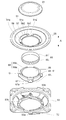
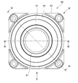
第1実施形態を説明する。図1は本発明のスピーカユニットの第1実施形態を説明する分解斜視図、図2は図1を組み付けた際の正面図、図3は図2の背面図、図4は図2のIV方向矢視図、図5は図2のV方向矢視図、図6は図2の切断線VI-VIでの断面図、図7は図2の切断線VII-VIIでの断面図である。
第1実施形態を説明する。図1は本発明のスピーカユニットの第1実施形態を説明する分解斜視図、図2は図1を組み付けた際の正面図、図3は図2の背面図、図4は図2のIV方向矢視図、図5は図2のV方向矢視図、図6は図2の切断線VI-VIでの断面図、図7は図2の切断線VII-VIIでの断面図である。
最初に、本実施形態のスピーカユニット50の全体構成を説明する。
振動板51の外周部51bは、エッジ55を介してフレーム53に取り付けられている。
振動板51は、外周部51bから内周部51cにかけて中央がへこんだ形状とされ、中央(内周部51c)に振動板51の厚み方向に貫通する円形の中心穴51aが形成されている。又、フレーム53は、振動板51と同じ方向に中央がへこんだ形状とされ、中央に底部53aを有し、さらに底部53aには厚み方向に貫通する穴53bが形成されている。
振動板51の外周部51bは、エッジ55を介してフレーム53に取り付けられている。
振動板51は、外周部51bから内周部51cにかけて中央がへこんだ形状とされ、中央(内周部51c)に振動板51の厚み方向に貫通する円形の中心穴51aが形成されている。又、フレーム53は、振動板51と同じ方向に中央がへこんだ形状とされ、中央に底部53aを有し、さらに底部53aには厚み方向に貫通する穴53bが形成されている。
フレーム53の底部53aには、磁気回路61が設けられている。この磁気回路61は、ヨーク63と、マグネット65と、ポールピース66とからなっている。
ヨーク63は、難磁性材料でなり、一方の面が開放面となった有底円筒状で、フレーム53の底部53aの穴53bに取り付けられる基部67と、基部67の周縁から振動板51の振動方向(図1、図4-図7において矢印A方向)に沿って、フレーム53の底部53aから離れる方向に延出し、磁気回路61の外周円筒部として機能する円筒状の円筒部69と、を有している(図6参照)。すなわち、円筒部69が、本発明における外周円筒部とされる。円筒部69には、その開放面側の端部から振動板51の振動方向(矢印A方向)に沿って基部67に向かって延びる複数の立壁部69cとスリット69aとが形成されている。
本実施形態のスリット69aは、円筒部69の円周方向に沿って90°ピッチで4つ設けられている。よって、円筒部69は、4つのスリット69aと、この4つのスリット69aにより分けられた4つの立壁部69cと、からなっている。また、基部67には、スリット69aに対応して、外側に延出する4つの取付け部67aが形成されている。これら4つの取付け部67aが、フレーム53の穴53bの周縁に形成された4つの取り付け凹部53cに嵌合することにより、磁気回路61のフレーム53に対する位置決めがなされる。
マグネット65は、円板状に形成され、ヨーク63の基部67上に載置される。マグネット65の着磁方向は、振動板51の振動方向(矢印A方向)となっている。マグネット65上には、難磁性材料でなる円板状のポールピース66が載置されている。よって、ヨーク63の円筒部69の内周面と、ポールピース66の外周面との間に環状の空間が形成され、この環状の空間は、周方向に略均一な磁界が発生する磁気ギャップGとなっている。
振動板51の内周部51cには、磁気回路61のヨーク63の立壁部69cが挿通する4つの挿入穴57と、磁気回路61のヨーク63のスリット69aに挿通する4つの挿通部59と、が周方向に沿って交互に形成されている。挿入穴57は、振動板51の振動方向(厚み方向)に貫通している。この挿入穴57が、本発明における立壁挿入部とされる。また、振動板51の内周部51cは、各挿入穴57よりも振動板51の内周側に形成されたリング状の内側環状部591と、各挿入穴57よりも振動板51の外周側に形成されたリング状の外側環状部592と、を有している。したがって、内側環状部591と外側環状部592との間に各挿入穴57が形成されている。なお、本実施形態において、内側環状部591の内周面(内周部51cの内周面)により、振動板51の中心穴51aが形成されている。 そして、内側環状部591の内周面がボイスコイル85に接続されている 。
なお、図示は省略するが、振動板51の立壁挿入部として、振動板51の挿入穴57の代わりに、振動板51の中心穴51aの内周面に開口した切り欠き形状を形成してもよい。この場合、内側環状部591を形成することなく、各挿通部59の内周面をボイスコイル85に接続するとよい。
ボイスコイル85は、ヨーク63の円筒部69(立壁部69c)の内周面と、マグネット65及びポールピース66の外周面との間に配置される筒状のボビン81と、ボビン81の外周面に巻回されたコイル83と、からなっている。そして、コイル83が磁気回路61の磁気ギャップGに位置するように、ボビン81と振動板51の中心穴51aの内周面(振動板51の内周部51cの内周面)とが接続されている。即ち、磁気回路61のヨーク63のスリット69aを介して振動板51の内周部51cの内周面(内側環状部591の内周面)とボイスコイル85とが接続されている。
また、振動板51の振動方向(矢印A方向)のうち、振動板51が磁気回路61(ヨーク63の基部67)から離れる方向を上、振動板51が磁気回路61へ近づく方向を下とした場合、ボビン81の下部に振動板51の中心穴51aの内周面(振動板51の内周部51cの内周面)が接続されている。さらに、詳しく説明すると、ヨーク63の基部67側に配置されるボビン81の外周面、即ち、コイル83の下側のボビン81の外周面に振動板51の中心穴51aの内周面(振動板51の内周部51cの内周面)が接続されている。
そして、 図7に示すように、振動板51は、外周部51bと内周部51cとが一体に形成されている。また、振動板51の内周部51cの厚みが外周部51bの厚みより大きく(厚く)形成されている。
更に、振動板51の内周部51cは振動方向(矢印A方向)の下側に向かうにつれて漸次縮径する形状に形成されており、振動板51の内周部51cにおいて、外側環状部592よりも内側環状部591が振動方向(矢印A方向)の下側に配置されている。
また、図6に示すように、振動板51の振動方向(矢印A方向)において、振動板51とボビン81との接着面の厚み(t1)が、外周部51bの厚み(t2) より大きく(厚く)形成されている。
更に、振動板51の内周部51cは振動方向(矢印A方向)の下側に向かうにつれて漸次縮径する形状に形成されており、振動板51の内周部51cにおいて、外側環状部592よりも内側環状部591が振動方向(矢印A方向)の下側に配置されている。
また、図6に示すように、振動板51の振動方向(矢印A方向)において、振動板51とボビン81との接着面の厚み(t1)が、外周部51bの厚み(t2) より大きく(厚く)形成されている。
振動板51の一部を構成するダストキャップ91は、振動板51の中心穴51aからの塵埃等の浸入を防止するために用いられる。ダストキャップ91は、図6、図7に示すように、ボビン81の開口を覆うドーム状のドーム部91cと、振動板51に接続される振動板接続部91aと、ボイスコイル85に接続されるボイスコイル接続部91bと、を有している。振動板接続部91aは、ダストキャップ91の最も外周側に形成されており、振動板51の内周部51cの上側を覆っている。また、ボイスコイル接続部91bは、振動板接続部91aよりも内周側に形成されている。
図6では、ダストキャップ91のボイスコイル接続部91bは、ボイスコイル85のコイル83よりも上側のボビン81の外周面(ボビン81の上部)に接続されている。一方、ダストキャップ91の振動板接続部91aの外周縁は、振動板51の内周部51cと外周部51bとの境界付近に位置する内周部51cの外周側に接続されている。また、前述したように、コイル83の下側のボビン81の外周面に振動板51の中心穴51aの内周面(内側環状部591の内周面)が接続されている。このように、振動板51の内周部51cの内周面がボビン81の下部に接続され、内周部51cの外周側がダストキャップ91の振動板接続部91aの外周縁に接続され、ダストキャップ91のボイスコイル接続部91bがボビン81の上部に接続されている。そして、振動板51の内周部51cの上側が振動板接続部91aで覆われることにより、振動板接続部91aの内側には、振動板51の内周部51cとダストキャップ91の振動板接続部91aとボイスコイル85とで囲まれた内部空間が形成されている。
又、図3において、フレーム53にはターミナル52が設けられており、ターミナル52とボイスコイル85のコイル83とは、図示しない錦糸線(リード線)で電気的に接続されている。
次に、上記構成のスピーカユニット50の作動を説明する。ターミナル52に入力される電気信号は、錦糸線を介してボイスコイル85のコイル83に流れる。コイル83は、磁気回路61によって発生する磁界内に配置されているので、コイル83(ボイスコイル85)に発生する駆動力により、振動板51が矢印A方向に振動し、音が放射される。
上記構成によれば、以下のような効果が得られる。
(1) 振動板51は、磁気回路61の円筒部69の立壁部69cが挿通する挿入穴57と、円筒部69のスリット69aに挿通する挿通部59と、を有することにより、磁気回路61の先端(ヨーク63の先端)よりも下側に振動板51とボイスコイル85との接着面を配置できる。このため、振動板51の振動方向の高さを低くすることなく、スピーカユニット50の薄型化が図れる。また、振動板51のコーン形状の高低差を十分に確保できるので、振動板51全体の剛性が低下することを抑制できる。
(1) 振動板51は、磁気回路61の円筒部69の立壁部69cが挿通する挿入穴57と、円筒部69のスリット69aに挿通する挿通部59と、を有することにより、磁気回路61の先端(ヨーク63の先端)よりも下側に振動板51とボイスコイル85との接着面を配置できる。このため、振動板51の振動方向の高さを低くすることなく、スピーカユニット50の薄型化が図れる。また、振動板51のコーン形状の高低差を十分に確保できるので、振動板51全体の剛性が低下することを抑制できる。
(2) 振動板51の中心穴51aの内周面(振動板51の内周部51cの内周面)とボイスコイル85の下部(ヨーク63の基部67側)とを接続することにより、振動板51の振動方向の高さを低くすることなく、確実にスピーカユニット50の薄型化が図れる。
(3) スピーカユニットを薄型化するために従来必要であった二重リングが不要となり、部品点数が減り、コストダウンが図れる。
(4) ボイスコイル85により駆動され振動する部分が振動板51だけとなり、質量が軽くなるので、強力な磁気回路が不要となり、コストダウンが図れる。
(5) 振動する部分の質量が軽くなるので、振動板51の応答がよく、音質がよくなる。
(6) ダストキャップ91は、振動板51に接続される振動板接続部91aと、ボイスコイル85に接続されるボイスコイル接続部91bと、を有することで、振動板51の剛性が高くなる。よって、振動板51内での音が伝播する速度が速くなり、反応(トランジェット特性)がよく、緻密で繊細な音が再現できる。
(7) 振動板51の内周部51cと外周部51bとが一体に成形されていることにより、振動板51の剛性を高くすることができる。
(8) 振動板51の内周部51cの厚みが振動板51の外周部51bの厚みより大きいことにより、振動板51の内周部51cの剛性を高めながら、振動板51の質量が増加することを抑制できる。
(9) 振動板51の内周部51cとボビン81との接着面の振動方向の厚み(t1)が、振動板51の外周部51bの厚み(t2)より大きいことにより、ボビン81と振動板51との接着面積を増加でき、スピーカユニット50の耐久性を向上できる。
(10) 振動板51の内側環状部591とボイスコイル85の下部とを接続し、ダストキャップ91のボイスコイル接続部91bとボイスコイル85の上部とを接続し、ダストキャップ91の振動板接続部91aと振動板51の外側環状部592付近とを接続することで、振動板51の内周部51cに挿入穴57を形成しても、振動板51の剛性が低下すること防止でき、振動板51のコーン形状を維持できる。
<第2実施形態>
第1実施形態では、ボイスコイルを支持するダンパがない構成のスピーカユニット50で説明を行ったが、図8、図9に示すように、スピーカユニットには、さらにボイスコイルを支持するダンパを設けても良い。
第1実施形態では、ボイスコイルを支持するダンパがない構成のスピーカユニット50で説明を行ったが、図8、図9に示すように、スピーカユニットには、さらにボイスコイルを支持するダンパを設けても良い。
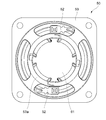
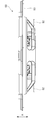
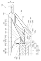
図8は本発明の第2実施形態のスピーカユニット150の半断面図、図9は図8のダンパ201の斜視図である。
最初に、実施の形態のスピーカユニット150の全体構成を説明する。
最初に、実施の形態のスピーカユニット150の全体構成を説明する。
振動板151の外周部151bは、エッジ155を介してフレーム153に取り付けられている。振動板151は、外周部151bから内周部151cにかけて中央がへこんだ形状とされ、中央(内周部151c)に振動板151の厚み方向に貫通する円形の中心穴151aが形成されている。
又、フレーム153は、振動板151と同じ方向に中央がへこんだ形状とされ、中央に底部153aを有し、さらに底部153aには厚み方向に貫通する穴153bが形成されている。フレーム153の底部153aには、磁気回路161が設けられている。この磁気回路161は、ヨーク163と、マグネット165と、ポールピース166とからなっている。
ヨーク163は、難磁性材料でなり、一方の面が開放面となった有底円筒状で、フレーム153の底部153aの穴153bに取り付けられる基部167と、基部167の周縁から振動板151の振動方向(図8において矢印A’方向)に沿って、フレーム153の底部153aから離れる方向に延出し、磁気回路161の外周円筒部として機能する円筒状の円筒部169と、を有している。すなわち、円筒部169が、本発明における外周円筒部とされる。円筒部169には、その開放面側の端部から振動板151の振動方向(矢印A’方向)に沿って基部167に向かって延びる複数の立壁部169cとスリット169aとが形成されている。
本実施形態のスリット169aは、円筒部169の円周方向に沿って90°ピッチで4つ設けられている。よって、円筒部169は、4つのスリット169aと、この4つのスリット169aにより分けられた4つの立壁部169cと、からなっている。
マグネット165は、円板状に形成され、ヨーク163の基部167上に載置される。マグネット165の着磁方向は、振動板151の振動方向(矢印A’方向)となっている。マグネット165上には、難磁性材料でなる円板状のポールピース166が載置されている。よって、ヨーク163の円筒部169の内周面と、ポールピース166の外周面との間に環状の空間が形成され、この環状の空間は、周方向に略均一な磁界が発生する磁気ギャップG’となっている。
振動板151は第1実施形態の振動板51と同じ形状であり、振動板151の内周部151cには、磁気回路161のヨーク163の立壁部169cが挿通する4つの挿入穴(立壁挿入部)157と、磁気回路161のヨーク163のスリット169aに挿通する4つの挿通部159と、が周方向に沿って交互に形成されている。挿入穴157は、振動板151の振動方向(厚み方向)に貫通している。
ボイスコイル185は、ヨーク163の円筒部169(立壁部169c)の内周面と、マグネット165及びポールピース166の外周面との間に配置される筒状のボビン181と、ボビン181の外周面に巻回されたコイル183と、からなっている。そして、コイル183が磁気回路161の磁気ギャップG’に位置するように、ボビン181と振動板151の中心穴151aの内周面(振動板151の内周部151cの内周面)とが接続されている。即ち、磁気回路161のヨーク163のスリット169aを介して振動板151の内周部151cの内周面とボイスコイル185とが接続されている。
また、振動板151の振動方向(矢印A’方向)のうち、振動板151が磁気回路161(ヨーク163の基部167)から離れる方向を上、振動板151が磁気回路161へ近づく方向を下とした場合、ボビン181の下部に振動板151の中心穴151aの内周面(振動板151の内周部151cの内周面)が接続されている。さらに、詳しく説明すると、ヨーク163の基部167側に配置されるボビン181の外周面、即ち、コイル183の下側のボビン181の外周面に振動板151の中心穴151aの内周面(振動板151の内周部151cの内周面)が接続されている。
そして、振動板151は、外周部151bと内周部151cとが一体に形成されている。また、振動板151の内周部151cの厚みが外周部151bの厚みより大きく(厚く)形成されている。
振動板151の一部を構成するダストキャップ191は、振動板151の中心穴151aからの塵埃等の浸入を防止するために用いられる。ダストキャップ191は、ボビン181の開口を覆うドーム状のドーム部191cと、振動板151に接続される振動板接続部191aと、ボイスコイル185に接続されるボイスコイル接続部191bと、を有している。振動板接続部191aは、ダストキャップ191の最も外周側に形成されており、振動板151の内周部151cの上側を覆っている。また、ボイスコイル接続部191bは、振動板接続部191aよりも内周側に形成されている。
ダストキャップ191のボイスコイル接続部191bは、ボイスコイル185のコイル183よりも上側のボビン181の外周面(ボビン181の上部)に接続されている。一方、ダストキャップ191の振動板接続部191aの外周縁は、振動板151の内周部151cと外周部151bとの境界付近に位置する内周部51cの外周側に接続されている。また、前述したように、コイル183の下側のボビン181の外周面に振動板151の中心穴151aの内周面が接続されている。このように、振動板151の内周部151cの内周面がボビン181の下部に接続され、内周部151cの外周側がダストキャップ191の振動板接続部191aの外周縁に接続され、ダストキャップ191のボイスコイル接続部191bがボビン181の上部に接続されている。そして、振動板151の内周部151cの上側が振動板接続部191aで覆われることにより、振動板接続部191aの内側には、振動板151の内周部151cとダストキャップ191の振動板接続部191aとボイスコイル185とで囲まれた内部空間が形成されている。
本実施形態では、ボイスコイル185を支持するダンパ201を有している。図9に示すように、ダンパ201は、フレーム153に接続されるアウタリング部203と、ボイスコイル185に接続されるインナリング部205と、アウタリング部203とインナリング部205との間を橋渡しする橋絡部207と、これらアウタリング部203とインナリング部205と橋絡部207とに囲まれた開口部209と、を有する。アウタリング部203とインナリング部205とは同心状に形成されており、アウタリング部203の内側にインナリング部205が配置されている。
アウタリング部203は、フレーム153の下部側に接続され、エッジ155よりも下側でフレーム153に接続されている。また、インナリング部205は、ボイスコイル185のボビン181と振動板151との接続箇所よりさらに下側でボビン181に接続されている。橋絡部207は、アウタリング部203の半径方向に延出し、アウタリング部203とインナリング部205とを橋渡しするように設けられている。図9では、ダンパ201は4つの橋絡部207を有している。開口部209は振動板151の振動方向(ダンパ201の厚み方向)に貫通しており、橋絡部207と同数の4つ設けられている。なお、橋絡部207と開口部209の数は、4つずつに限られるものではなく、その他の数を設けることができる。
各橋絡部207は、磁気回路161のヨーク163の各スリット169aに挿通している。また、橋絡部207は、半径方向に沿った断面形状が波形となっており、振動板151の振動方向(矢印A’方向)に橋絡部207が撓むことにより、このダンパ201に支持されるボイスコイル185は矢印A’方向に移動可能となっている。また、各開口部209は、磁気回路161のヨーク163の各立壁部169cを挿通している。
次に、上記構成のスピーカユニット150の作動を説明する。電気信号がボイスコイル185のコイル183に流れる。コイル183は、磁気回路161によって発生する磁界に配置されているので、コイル183(ボイスコイル185)に発生する駆動力により、振動板151が矢印A’方向に振動し、音が放射される。
上記構成によれば、以下のような効果が得られる。
(1) 振動板151は、磁気回路161の円筒部169の立壁部169cが挿通する挿入穴157と、円筒部169のスリット169aに挿通する挿通部159と、を有することにより、磁気回路161の先端(ヨーク166)よりも下側に振動板151とボイスコイル185との接着面を配置できる。このため、振動板151の振動方向の高さを低くすることなく、スピーカユニット150の薄型化が図れる。また、振動板151のコーン形状の高低差を十分に確保できるので、振動板151全体の剛性が低下することを抑制できる。
(1) 振動板151は、磁気回路161の円筒部169の立壁部169cが挿通する挿入穴157と、円筒部169のスリット169aに挿通する挿通部159と、を有することにより、磁気回路161の先端(ヨーク166)よりも下側に振動板151とボイスコイル185との接着面を配置できる。このため、振動板151の振動方向の高さを低くすることなく、スピーカユニット150の薄型化が図れる。また、振動板151のコーン形状の高低差を十分に確保できるので、振動板151全体の剛性が低下することを抑制できる。
(2) 振動板151の中心穴151aの内周面(振動板151の内周部151cの内周面)とボイスコイル185の下部(ヨーク163の基部167側)とを接続することにより、振動板151の振動方向の高さを低くすることなく、確実にスピーカユニット150の薄型化が図れる。
(3) スピーカユニットを薄型化するために従来必要であった二重リングが不要となり、部品点数が減り、コストダウンが図れる。
(4) ボイスコイル185により駆動され振動する部分が振動板151だけとなり、質量が軽くなるので、強力な磁気回路が不要となり、コストダウンが図れる。
(5) 振動する部分の質量が軽くなるので、振動板151の応答がよく、音質がよくなる。
(6) ダストキャップ191は、振動板151に接続される振動板接続部191aと、ボイスコイル185に接続されるボイスコイル接続部191bと、を有することで、振動板151の剛性が高くなる。よって、振動板151内での音が伝播する速度が速くなり、反応(トランジェット特性)がよく、緻密で繊細な音が再現できる。
(7) 振動板151の内周部151cと外周部151bとが一体に成形されていることにより、振動板151の剛性を高くすることができる。
(8) 振動板151の内周部151cの厚みが振動板151の外周部151bの厚みより大きいことにより、振動板151の内周部151cの剛性を高めながら、振動板151の質量が増加することを抑制できる。
(9) ボイスコイル185を支持するダンパ201を有することで、ボイスコイル185をエッジ155及び振動体151を介してフレーム153に支持するだけでなく、ダンパ201を介してフレーム153に支持できる。したがって、エッジ155及び振動体151とダンパ201とにより、ボイスコイル185の振動方向の振動を安定して支持できる。また、振動板151が大口径で、ボイスコイル185が大型化してもダンパ201により安定して支持することができ、音質が良くなる。
50、150 スピーカユニット
51、151 振動板
51a、151a 中心穴
51b、151b 外周部
51c、151c 内周部
53、153 フレーム
57、157 挿入穴(立壁挿入部)
59、159 挿通部
61、161 磁気回路
69、169 円筒部(外周円筒部)
69a、169a スリット
69c、169c 立壁部
85、185 ボイスコイル
A、A’ 振動板の振動方向
G、G’ 磁気ギャップ
51、151 振動板
51a、151a 中心穴
51b、151b 外周部
51c、151c 内周部
53、153 フレーム
57、157 挿入穴(立壁挿入部)
59、159 挿通部
61、161 磁気回路
69、169 円筒部(外周円筒部)
69a、169a スリット
69c、169c 立壁部
85、185 ボイスコイル
A、A’ 振動板の振動方向
G、G’ 磁気ギャップ
Claims (9)
- 外周円筒部を有し、前記外周円筒部の内側に磁気ギャップとなる環状の空間が形成された磁気回路と、
前記磁気ギャップに配置されるボイスコイルと、
中央に貫通する中心穴を有し、外周部側がフレームに支持され、内周部の内周面が前記ボイスコイルに接続される振動板と、を有し、
前記磁気回路の外周円筒部が、前記振動板の振動方向に沿って形成された立壁部と、スリットと、を有し、
前記振動板の内周部は、前記立壁部が挿通する立壁挿入部と、前記スリットに挿通する挿通部と、を有する
ことを特徴とするスピーカユニット。 - 前記ボイスコイルを覆うダストキャップを設け、
該ダストキャップは、前記振動板と前記ボイスコイルとに接続されている
ことを特徴とする請求項1に記載のスピーカユニット。 - 前記振動板の振動方向のうち、前記振動板が前記磁気回路から離れる方向を上、前記振動板が前記磁気回路へ近づく方向を下とした場合、
前記振動板の内周部の内周面を前記ボイスコイルの下部に接続した
ことを特徴とする請求項1に記載のスピーカユニット。 - 前記立壁挿入部は、前記振動板の振動方向に貫通する挿入穴であり、
前記振動板の内周部は、各挿入穴よりも前記振動板の内周側に形成されたリング状の内側環状部を有し、
前記内側環状部の内周面が前記ボイスコイルに接続される
ことを特徴とする請求項1に記載のスピーカユニット。 - 前記振動板の内周部と外周部とが一体に成形されている
ことを特徴とする請求項1に記載のスピーカユニット。 - 前記振動板の内周部の厚みが前記振動板の外周部の厚みより大きい
ことを特徴とする請求項1に記載のスピーカユニット。 - 前記振動板の振動方向において、
前記振動板の内周部と前記ボイスコイルとの接着面の厚みが、前記振動板の外周部の厚みより大きい
ことを特徴とする請求項1記載のスピーカユニット。 - 前記ダストキャップは、
該ダストキャップの外周側に形成され、前記振動板と接続される振動板接続部と、
前記振動板接続部よりも内周側に形成され、前記ボイスコイルの上部と接続されるボイスコイル接続部と、を有する
ことを特徴とする請求項2に記載のスピーカユニット。 - 前記フレームに接続されるアウタリング部と、
前記ボイスコイルに接続されるインナリング部と、
前記アウタリング部と前記インナリング部との間を橋渡し、前記スリットに挿通する橋絡部と、
前記立壁部を挿通する開口部と、を有するダンパをさらに有する
ことを特徴とする請求項1記載のスピーカユニット。
Priority Applications (4)
| Application Number | Priority Date | Filing Date | Title |
|---|---|---|---|
| CN201880065429.5A CN111194560B (zh) | 2017-10-13 | 2018-08-22 | 扬声器单元 |
| US16/755,622 US11284198B2 (en) | 2017-10-13 | 2018-08-22 | Speaker unit |
| EP18866099.7A EP3697105A4 (en) | 2017-10-13 | 2018-08-22 | SPEAKER UNIT |
| JP2019547935A JP6990250B2 (ja) | 2017-10-13 | 2018-08-22 | スピーカユニット |
Applications Claiming Priority (2)
| Application Number | Priority Date | Filing Date | Title |
|---|---|---|---|
| JP2017199021 | 2017-10-13 | ||
| JP2017-199021 | 2017-10-13 |
Publications (1)
| Publication Number | Publication Date |
|---|---|
| WO2019073697A1 true WO2019073697A1 (ja) | 2019-04-18 |
Family
ID=66101419
Family Applications (1)
| Application Number | Title | Priority Date | Filing Date |
|---|---|---|---|
| PCT/JP2018/030983 Ceased WO2019073697A1 (ja) | 2017-10-13 | 2018-08-22 | スピーカユニット |
Country Status (5)
| Country | Link |
|---|---|
| US (1) | US11284198B2 (ja) |
| EP (1) | EP3697105A4 (ja) |
| JP (1) | JP6990250B2 (ja) |
| CN (1) | CN111194560B (ja) |
| WO (1) | WO2019073697A1 (ja) |
Cited By (1)
| Publication number | Priority date | Publication date | Assignee | Title |
|---|---|---|---|---|
| WO2022006964A1 (zh) * | 2020-07-06 | 2022-01-13 | 瑞声声学科技(深圳)有限公司 | 扬声器 |
Families Citing this family (1)
| Publication number | Priority date | Publication date | Assignee | Title |
|---|---|---|---|---|
| CN118317229A (zh) * | 2022-12-30 | 2024-07-09 | 迪芬尼香港有限公司 | 振膜组件、制造振膜组件的方法及射出成型的模具 |
Citations (6)
| Publication number | Priority date | Publication date | Assignee | Title |
|---|---|---|---|---|
| JPS61396U (ja) * | 1984-06-04 | 1986-01-06 | オンキヨー株式会社 | 平板型スピ−カ− |
| JPH01225299A (ja) * | 1988-03-04 | 1989-09-08 | Mitsubishi Electric Corp | コーンスピーカーの振動板結合装置 |
| JPH07154896A (ja) * | 1993-11-29 | 1995-06-16 | Matsushita Electric Ind Co Ltd | スピーカ |
| JP2002078082A (ja) | 2000-09-04 | 2002-03-15 | Matsushita Electric Ind Co Ltd | スピーカ |
| JP2002159091A (ja) * | 2000-11-20 | 2002-05-31 | Matsushita Electric Ind Co Ltd | スピーカ及び振動板並びに振動板の製造方法 |
| JP2011004308A (ja) * | 2009-06-22 | 2011-01-06 | Foster Electric Co Ltd | スピーカ装置 |
Family Cites Families (24)
| Publication number | Priority date | Publication date | Assignee | Title |
|---|---|---|---|---|
| JPS5856600A (ja) * | 1981-09-30 | 1983-04-04 | Hitachi Ltd | 平面形スピ−カ |
| JPS60155278A (ja) | 1983-11-21 | 1985-08-15 | Somar Corp | 粉体塗料用エポキシ樹脂組成物 |
| DE3929266C1 (ja) * | 1989-09-02 | 1991-01-03 | Mercedes-Benz Aktiengesellschaft, 7000 Stuttgart, De | |
| JP3260062B2 (ja) * | 1995-09-04 | 2002-02-25 | 株式会社ケンウッド | スピーカ |
| CN1179692A (zh) * | 1996-05-23 | 1998-04-22 | 日本先锋公司 | 扬声器 |
| JP3505037B2 (ja) * | 1996-05-23 | 2004-03-08 | パイオニア株式会社 | スピーカ |
| JPH09327087A (ja) * | 1996-06-06 | 1997-12-16 | Matsushita Electric Ind Co Ltd | ダブルコーンスピーカ |
| US6842529B2 (en) * | 2000-09-04 | 2005-01-11 | Matsushita Electric Industrial Co., Ltd. | Speaker |
| US7209570B2 (en) * | 2001-06-11 | 2007-04-24 | Matsushita Electric Industrial Co., Ltd. | Speaker |
| US6968071B2 (en) * | 2003-01-15 | 2005-11-22 | Chao-Lang Wang | Speaker having magnetic member installed on diaphragm |
| JP3651470B2 (ja) * | 2003-03-31 | 2005-05-25 | 松下電器産業株式会社 | スピーカ |
| JP2005159506A (ja) * | 2003-11-21 | 2005-06-16 | Pioneer Electronic Corp | スピーカ装置 |
| JP4610890B2 (ja) * | 2003-12-24 | 2011-01-12 | パイオニア株式会社 | スピーカ装置 |
| JP2005252924A (ja) * | 2004-03-08 | 2005-09-15 | Matsushita Electric Ind Co Ltd | スピーカ |
| CN200973173Y (zh) | 2006-11-16 | 2007-11-07 | 常州美欧电子有限公司 | 振动发声器 |
| CN200997173Y (zh) | 2006-12-05 | 2007-12-26 | 哈尔滨自动化仪表研究所 | 供热温度检测仪 |
| JP5190033B2 (ja) * | 2009-07-03 | 2013-04-24 | ホシデン株式会社 | 振動センサ |
| CN101626535B (zh) * | 2009-08-17 | 2014-06-18 | 瑞声声学科技(深圳)有限公司 | 发声器 |
| CN102932716A (zh) * | 2011-08-08 | 2013-02-13 | 美隆工业股份有限公司 | 内支架喇叭结构 |
| US9078059B2 (en) | 2012-08-07 | 2015-07-07 | Jabil Circuit (Beijing), Ltd. | Transducer |
| CN103118320B (zh) * | 2013-01-18 | 2015-11-11 | 歌尔声学股份有限公司 | 一种超薄扬声器模组 |
| CN104822115B (zh) * | 2015-05-08 | 2018-11-02 | 歌尔股份有限公司 | 一种扬声器装置 |
| JPWO2017149984A1 (ja) * | 2016-02-29 | 2018-12-20 | パナソニックIpマネジメント株式会社 | スピーカ |
| JP2020114308A (ja) | 2019-01-18 | 2020-07-30 | 株式会社三共 | 遊技機 |
-
2018
- 2018-08-22 WO PCT/JP2018/030983 patent/WO2019073697A1/ja not_active Ceased
- 2018-08-22 US US16/755,622 patent/US11284198B2/en active Active
- 2018-08-22 JP JP2019547935A patent/JP6990250B2/ja active Active
- 2018-08-22 EP EP18866099.7A patent/EP3697105A4/en active Pending
- 2018-08-22 CN CN201880065429.5A patent/CN111194560B/zh active Active
Patent Citations (6)
| Publication number | Priority date | Publication date | Assignee | Title |
|---|---|---|---|---|
| JPS61396U (ja) * | 1984-06-04 | 1986-01-06 | オンキヨー株式会社 | 平板型スピ−カ− |
| JPH01225299A (ja) * | 1988-03-04 | 1989-09-08 | Mitsubishi Electric Corp | コーンスピーカーの振動板結合装置 |
| JPH07154896A (ja) * | 1993-11-29 | 1995-06-16 | Matsushita Electric Ind Co Ltd | スピーカ |
| JP2002078082A (ja) | 2000-09-04 | 2002-03-15 | Matsushita Electric Ind Co Ltd | スピーカ |
| JP2002159091A (ja) * | 2000-11-20 | 2002-05-31 | Matsushita Electric Ind Co Ltd | スピーカ及び振動板並びに振動板の製造方法 |
| JP2011004308A (ja) * | 2009-06-22 | 2011-01-06 | Foster Electric Co Ltd | スピーカ装置 |
Cited By (1)
| Publication number | Priority date | Publication date | Assignee | Title |
|---|---|---|---|---|
| WO2022006964A1 (zh) * | 2020-07-06 | 2022-01-13 | 瑞声声学科技(深圳)有限公司 | 扬声器 |
Also Published As
| Publication number | Publication date |
|---|---|
| EP3697105A4 (en) | 2020-12-09 |
| EP3697105A1 (en) | 2020-08-19 |
| JPWO2019073697A1 (ja) | 2020-10-22 |
| CN111194560B (zh) | 2022-02-22 |
| JP6990250B2 (ja) | 2022-01-12 |
| US20200336838A1 (en) | 2020-10-22 |
| CN111194560A (zh) | 2020-05-22 |
| US11284198B2 (en) | 2022-03-22 |
Similar Documents
| Publication | Publication Date | Title |
|---|---|---|
| US8290199B2 (en) | Loudspeaker suspension | |
| US20200413184A1 (en) | Loudspeaker | |
| JP6005974B2 (ja) | 薄型ラウドスピーカ変換器用の強化振動板 | |
| KR101499514B1 (ko) | 장방형의 일체형 투웨이 스피커 | |
| JP6123838B2 (ja) | 電気音響変換器 | |
| JP6029846B2 (ja) | ラウドスピーカ磁石組立体 | |
| CN107409259B (zh) | 电子音响变换装置 | |
| US20040076309A1 (en) | Audio radiator with radiator flexure minimization and voice coil elastic anti-wobble members | |
| JP2012222832A (ja) | チャネルを有するラウドスピーカ磁石 | |
| CN105765995A (zh) | 扬声器 | |
| US20080285787A1 (en) | Thin loudspeaker | |
| WO2019073697A1 (ja) | スピーカユニット | |
| JP6029845B2 (ja) | 薄型ラウドスピーカサスペンションシステム | |
| CN110248297A (zh) | 一种多路输入驱动的小型扬声器及中高音扬声器 | |
| JP2008092560A (ja) | 電気音響変換器 | |
| JP4133457B2 (ja) | スピーカ | |
| CN115769600A (zh) | 电声换能器 | |
| JP4440001B2 (ja) | スピーカ | |
| KR101383765B1 (ko) | 스피커 | |
| JP4726091B2 (ja) | スピーカ装置 | |
| US12483837B2 (en) | Speaker driver assembly | |
| JPS5864899A (ja) | ラウドスピ−カ | |
| JP2003023695A (ja) | スピーカ装置 | |
| JP2007318345A (ja) | スピーカ装置 | |
| KR20230083480A (ko) | 비대칭 구조를 갖는 평판형 트위터 스피커 |
Legal Events
| Date | Code | Title | Description |
|---|---|---|---|
| 121 | Ep: the epo has been informed by wipo that ep was designated in this application |
Ref document number: 18866099 Country of ref document: EP Kind code of ref document: A1 |
|
| ENP | Entry into the national phase |
Ref document number: 2019547935 Country of ref document: JP Kind code of ref document: A |
|
| NENP | Non-entry into the national phase |
Ref country code: DE |
|
| ENP | Entry into the national phase |
Ref document number: 2018866099 Country of ref document: EP Effective date: 20200513 |