WO2019073991A1 - Dispositif processeur - Google Patents
Dispositif processeur Download PDFInfo
- Publication number
- WO2019073991A1 WO2019073991A1 PCT/JP2018/037660 JP2018037660W WO2019073991A1 WO 2019073991 A1 WO2019073991 A1 WO 2019073991A1 JP 2018037660 W JP2018037660 W JP 2018037660W WO 2019073991 A1 WO2019073991 A1 WO 2019073991A1
- Authority
- WO
- WIPO (PCT)
- Prior art keywords
- udi
- unit
- processor
- processor device
- display body
- Prior art date
- Legal status (The legal status is an assumption and is not a legal conclusion. Google has not performed a legal analysis and makes no representation as to the accuracy of the status listed.)
- Ceased
Links
Images


Classifications
-
- A—HUMAN NECESSITIES
- A61—MEDICAL OR VETERINARY SCIENCE; HYGIENE
- A61B—DIAGNOSIS; SURGERY; IDENTIFICATION
- A61B1/00—Instruments for performing medical examinations of the interior of cavities or tubes of the body by visual or photographical inspection, e.g. endoscopes; Illuminating arrangements therefor
- A61B1/04—Instruments for performing medical examinations of the interior of cavities or tubes of the body by visual or photographical inspection, e.g. endoscopes; Illuminating arrangements therefor combined with photographic or television appliances
-
- A—HUMAN NECESSITIES
- A61—MEDICAL OR VETERINARY SCIENCE; HYGIENE
- A61B—DIAGNOSIS; SURGERY; IDENTIFICATION
- A61B1/00—Instruments for performing medical examinations of the interior of cavities or tubes of the body by visual or photographical inspection, e.g. endoscopes; Illuminating arrangements therefor
- A61B1/04—Instruments for performing medical examinations of the interior of cavities or tubes of the body by visual or photographical inspection, e.g. endoscopes; Illuminating arrangements therefor combined with photographic or television appliances
- A61B1/045—Control thereof
-
- G—PHYSICS
- G02—OPTICS
- G02B—OPTICAL ELEMENTS, SYSTEMS OR APPARATUS
- G02B23/00—Telescopes, e.g. binoculars; Periscopes; Instruments for viewing the inside of hollow bodies; Viewfinders; Optical aiming or sighting devices
- G02B23/24—Instruments or systems for viewing the inside of hollow bodies, e.g. fibrescopes
Definitions
- the present invention relates to a processor that controls an apparatus for observing or treating a subject.
- UDI Unique Device Identification
- GS1, HIBCC, etc. human-identifiable character displays and automatic identification displays
- Patent Document 1 proposes a processor that describes the date of manufacture of an imaging device in an internal memory of the imaging device.
- Patent Document 2 proposes a system for reading a serial identification number of an imaging device for single use (disposable) from a bar code.
- Patent Document 3 proposes an image management apparatus for reading a barcode of an endoscope scope with a barcode reader and acquiring an ID of the endoscope scope.
- the UDI including the device identifier and the manufacturing identifier is information that is effective not only in product management but also in utilizing the product. If UDI is recorded on the storage medium of the product, the traceability of the product can be assured, and it can be used for confirmation of compatibility among products.
- An object of this invention is to provide the processor apparatus which can record UDI easily on the storage medium of a product in view of the said subject.
- a processor device for controlling a device for observing or treating a subject is provided on a housing, a storage unit for storing input information, and an appearance surface of the housing.
- a display body for displaying information indicating a UDI (Unique Device Identification) including a device identifier and a manufacturing identifier of the processor device, and information indicating the UDI displayed on the display body after the manufacturing date of the processor device And an input unit for storing the manufacturing identifier of the processor unit extracted based on the storage unit in the storage unit.
- UDI Unique Device Identification
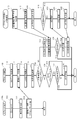
- FIG. 1 It is a figure which shows the structural example of the endoscope system which applied the product management system. It is a figure which shows a mode that the display body of a processor apparatus is image
- the product management system 1 is a system that stores (registers) UDI of a product in a storage unit of the product.
- the product management system 1 can also be applied to a microscope system or the like for observing a subject.
- processing for registering a UDI of a product in a storage unit of the product is also abbreviated as UDI registration processing.
- FIG. 1 is a diagram showing a configuration example of an endoscope system 2 to which a product management system 1 is applied.
- the product management system 1 is obtained by adding a tablet terminal 20 a as an information terminal to the endoscope system 2.
- the tablet terminal 20a is a specific example of an information terminal.
- the information terminal may be a smartphone or a digital camera with a communication function.
- the endoscope system 2 includes a processor device 10, an endoscope scope 20b, a light source device 50, an image recording device 60, and a monitor device 70.
- the tablet terminal 20a is not included in a normal endoscope system.
- either the tablet terminal 20a or the endoscope scope 20b is selectively adopted as the imaging device 20.
- the product management system 1 has the same configuration as the endoscope system 2.
- the endoscope system 2 may also include a keyboard for input.
- the processor device 10 is connected to the endoscope scope 20b, converts an electrical signal captured by an imaging device provided in the endoscope scope 20b into a video signal, and outputs image data.
- the processor device 10 has a function of performing various image processing such as various color emphasis and narrow band light observation.
- the processor device 10 is also called a video processor.
- the processor device 10 analyzes and extracts the UDI by performing image analysis processing on the video signal or the image data of the display body of the UDI photographed by the imaging device 20.
- the processor device 10 registers the UDI in the storage unit of the processor device 10 when the photographed object of the UDI is a display device of the processor device 10 itself.
- the processor device 10 transmits the UDI to another product (for example, the light source device 50) if the display body of the captured UDI is the other product (for example, the light source device 50).
- Other products register UDI in their storage unit.
- UDI includes at least a production identifier, and may include both a device identifier and a production identifier.
- the manufacturing identifier includes at least either the serial number of the product or the manufacturing date of the product.
- the processor device 10 displays a product selection screen which allows the photographer to select a product for which UDI is to be registered in the UDI registration processing.
- the selection of the product for registering the UDI will be described later with reference to FIG.
- the selected product is also referred to as a target product.
- the imaging device 20 captures an image of a display of UDI attached to a housing, an exterior, or the like of a product, and outputs a video signal or image data to the processor device 10.
- the imaging device 20 may be either the tablet terminal 20a or the endoscope scope 20b.
- the tablet terminal 20a has an imaging function.
- the endoscope scope 20b has flexibility and an elongated insertion portion, an imaging element provided at the distal end of the insertion portion for imaging a subject, a light guide for guiding illumination light to the distal end of the insertion portion, and the like. It has the operation part 340 etc. which operate the scope 20b (refer FIG. 2). Then, the endoscope scope 20 b is connected to a light source device 50 having a light source and a processor device 10 for processing an image signal.
- the light source device 50 generates light close to natural light with a xenon lamp, and sends the light to the tip of the endoscope scope 20b through the glass fiber bundle in the endoscope scope 20b.
- the light source device 50 may be interlocked with the processor device 10, and may have an automatic light adjustment (automatically adjust the brightness) function.
- the light source device 50 may incorporate a pump for sending water or air.
- the image recording device 60 performs a series of processing including recording, management, and editing of a high definition endoscopic image (moving image / still image).
- the monitor device 70 displays an image captured by the endoscope scope 20b.
- the monitor device 70 displays the guide screen created by the processor device 10 and the product selection screen described above.
- the guide screen is a screen for guiding the operation procedure of the UDI registration process.
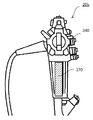
- FIG. 2 is a view showing how the display body 170 of the processor device 10 is photographed by the imaging device 20 (the tablet terminal 20a or the endoscope scope 20b).
- a display 170 for displaying information indicating UDI is provided on the front surface of the case 10a of the processor device 10.
- the display 170 shows an example of the barcode label 170a or the two-dimensional code label 170b.
- the QR code registered trademark
- the information indicating UDI may be uncoded characters or numbers.
- the display 170 is not limited to the label, and may be directly marked or printed on the housing 10 a. Further, the position of the display body 170 is not limited to the front surface of the housing 10a, but may be the back surface or the bottom surface.
- FIG.3 and FIG.4 is a functional block diagram of the process which registers UDI as an object product as the imaging device 20 the tablet terminal 20a.
- FIG. 3 is a first example of the product management system 1.
- FIG. 3 is a functional block diagram showing a process in which the tablet device 20 a captures the display 170 of the processor device 10 and the processor device 10 registers the UDI.
- the tablet terminal 20 a includes a control unit 200, a memory 210, a storage unit 220, an operation unit 240, a communication I / F 245, and an imaging unit 260.
- the control unit 200 centrally controls the entire tablet terminal 20a.
- the control unit 200 is realized by software processing by a CPU (not shown).
- the memory 210 temporarily stores the captured video signal and various data, and provides a working area.
- the storage unit 220 stores data in a non-volatile manner.
- the storage unit 220 stores an OS (Operating System) 222 which is basic software, a photographing application 224 which is software which performs control processing for image photographing, and the like.
- the storage unit 220 may store various tables and captured image data in addition to data such as software.
- the operation unit 240 receives an instruction from the operator and notifies the control unit 200 of the instruction.
- the operation unit 240 is, for example, a touch panel provided integrally with a display unit (not shown) or a press-type button.
- the communication I / F 245 transmits and receives data to and from an external device.
- the communication I / F 245 is configured, for example, in a format conforming to the standards of LAN (Local Area Network) and NFC (Near Field Communication).
- the imaging unit 260 includes an imaging unit such as a lens unit and a CMOS (Complementary MOS), and an imaging circuit, and photoelectrically converts an object image to generate image data.
- CMOS Complementary MOS
- the processor device 10 includes a control unit 100, a memory 110, a storage unit 120, an image processing unit 135, an operation unit 140, a communication I / F 145, a connection connector 150, a display 170, and the like.
- the control unit 100 controls the entire processor device 10 in an integrated manner.
- the control unit 100 is realized by software processing by a CPU described later.
- the control unit 100 includes an image analysis unit 102, an input unit 104, and an association unit 106 in order to execute the UDI registration process.
- the image analysis unit 102 analyzes and extracts the UDI by performing image analysis processing on the video signal or image data of the display of the UDI captured by the imaging device 20. That is, the image analysis unit 102 detects barcode (or QR code) information from the image captured by the imaging device 20, and analyzes and extracts UDI information from the code information.
- the image analysis unit 102 is also called an extraction unit.
- the image analysis unit 102 is realized by image analysis processing software 124 a described later.
- the input unit 104 inputs the UDI of the processor device 10 extracted by the image analysis unit 102 based on the information indicating the UDI displayed on the display body 170 into the storage unit 120 and stores the same.
- the input unit 104 inputs the extracted UDI to the storage unit 120 when the processor device 10 is selected as the target product.
- the input UDI is stored in the storage unit 120 as UDI information 126.
- the associating unit 106 associates the information (image data) generated inside the processor device 10 at the time of the examination by the endoscope scope 20 b with the UDI of the processor device 10. That is, the associating unit 106 associates the image data processed by the processor device 10 and stored in the storage unit 120 with the UDI of the processor device 10. For example, the associating unit 106 records the UDI (device identifier and manufacturing identifier) of the processor 10 as metadata of each of the photographed image data. Furthermore, in addition to the UDI of the processor device 10, the association unit 106 also records the UDI of the endoscope scope 20b related to imaging and the UDI of the light source device 50 as metadata of each image data captured. It is also good. This makes it possible not only to know the model name of the device or product involved in the imaging of the image but also to easily identify it as a unique product by the image data.
- the memory 110 temporarily stores the captured video signal and various data, and provides a working area.
- the storage unit 120 stores data in a non-volatile manner.
- the storage unit 120 stores an operating system (OS) 122 which is basic software, a UDI application 124 which analyzes and extracts UDI from an image in which a display body is photographed, UDI information 126 extracted by the UDI application 124 and the like. Be done.
- the UDI information 126 is stored after the UDI registration process is performed. Further, the storage unit 120 stores a UDI registration flag indicating a registration state of the UDI of the processor device 10. When the UDI is registered, the UDI registration flag is, for example, "1".
- the UDI device identifier of the product may be configured separately for hardware and software identifiers, in which case it is possible to register separately. Become. In this case, the UDI registration flag may be set to "1" only when an identifier related to hardware is registered. By separating the UDI registration flag from the registration of the software identifier, it is possible to update the software identifier in response to the software update of the target product.
- the UDI application 124 has an image analysis processing software 124 a.
- the image analysis processing software 124 a is software that performs processing of analyzing and extracting UDI from the image in which the display body is captured.
- the operation unit 140 receives various instructions from the operator and notifies the control unit 100.
- the communication I / F 145 transmits and receives data to and from an external device.
- the communication I / F 145 is configured, for example, in a format conforming to the standards of LAN (Local Area Network) and NFC (Near Field Communication).
- the connection connector 150 is a connector connected to the endoscope scope 20b.
- the video signal acquired by the endoscope scope 20 b is input to the processor device 10 through the connection connector 150.
- the display body 170 is a label on which a bar code or a two-dimensional code or the like indicating the UDI unique to the processor device 10 is printed. As described above, the display body 170 may be a marking on the housing 10a.
- the UDI registration process by the tablet terminal 20a and the processor device 10 shown in FIG. 3 will be briefly described.
- the processor 10 is set to the mode of UDI registration processing by the photographer, and the processor 10 is selected as the target product on the product selection screen. Photographing is performed by the photographer with the tablet terminal 20 a directed to the display body 170 of the processor device 10. Image data including a display 170 is transmitted from the tablet terminal 20 a to the processor device 10.
- the processor device 10 analyzes and extracts UDI from the image data including the display body 170 and inputs the UDI to the storage unit 120. As a result, the UDI of the processor device 10 is registered as the UDI information 126 in the storage unit 120 of the processor device 10.
- FIG. 4 is a second example of the product management system 1.
- FIG. 4 is a functional block diagram showing a process of registering the UDI in the light source device 50 by the tablet terminal 20 a and the processor device 10. That is, the functional block diagram for explaining the process of photographing the display body 570 of the light source device 50 with the tablet terminal 20a and registering the UDI information of the light source device 50 in the storage unit 520 of the light source device 50 via the processor device 10. It is.
- the configurations of the tablet terminal 20a and the processor device 10 are the same as those shown in FIG.
- the light source device 50 includes a control unit 500, a memory 510, a storage unit 520, a communication I / F 545, a display body 570, and the like.
- the control unit 500 generally controls the entire light source device 50.
- Control unit 500 is realized by software processing by a CPU (not shown).
- the memory 510 temporarily stores the OS 522 and various data, and provides a working area.
- Storage unit 520 stores data in a non-volatile manner.
- the storage unit 520 stores an operating system (OS) 522 which is basic software, an application 524 which is control software for the light source device 50, UDI information 526 unique to the light source device 50, and the like.
- the UDI information 526 is stored by executing the UDI registration process.
- the storage unit 520 stores a UDI registration flag indicating a registration state of the UDI of the light source device 50.
- the communication I / F 545 transmits and receives data to and from an external device.
- the display body 570 shows the UDI unique to the light source device 50.
- the display 570 is, for example, a label on which a barcode is printed as described above.
- the UDI registration process by the tablet terminal 20a, the processor device 10 and the light source device 50 shown in FIG. 4 will be briefly described.
- the processor 10 is set to the mode of UDI registration processing by the photographer, and the light source 50 is selected as the target product.
- the display body 570 of the light source device 50 is photographed by the tablet terminal 20 a, and the image data including the display body 570 is transmitted to the processor device 10 via the communication I / F 245 and the communication I / F 145.
- UDI is analyzed and extracted from the image data including the display body 570.
- the processor device 10 transmits the extracted UDI to the light source device 50 via the communication I / F 245 and the communication I / F 545.
- the light source device 50 stores the transmitted UDI as the UDI information 526 in the storage unit 520. Thereby, the UDI information 526 of the light source device 50 is registered in the storage unit 120 of the light source device 50.
- the image analysis unit 102 that analyzes and extracts the video signal or image data of the display object of UDI photographed by the imaging device 20 and analyzes and extracts the UDI is provided in the tablet terminal 20 a instead of the processor device 10 Also good. If the image analysis processing software 124 a is included in the imaging application 224, the processor device 10 can acquire the extracted UDI from the tablet terminal 20 a.
- FIG. 5 is a sequence diagram for explaining the flow of the UDI registration process using the tablet terminal 20a described in FIGS. 3 and 4 as the imaging device 20. It corresponds to the first example and the second example of the product management system 1 described above.
- the tablet terminal 20a is set to the photographing mode by the photographer.
- the control unit 200 executes the process in the shooting mode (step S10).
- the control unit 200 causes the imaging unit 260 to image the display object of the target product according to the operation instruction of the photographer (step S12).
- the target product is the processor device 10 or the light source device 50.
- the control unit 200 transmits, to the processor device 10, the image data in which the display body is captured from the communication I / F 245 (step S14).
- the control unit 100 activates the UDI application 124 (step T10).
- the control unit 100 receives, via the communication I / F 145, the image data obtained by capturing the display body transmitted from the tablet terminal 20a (step T12).
- the image data is stored in the memory 110.
- the image analysis unit 102 of the control unit 100 analyzes and extracts UDI from the image data (step T14).
- the control unit 100 displays a product selection screen on the monitor device 70, and allows the operator to select a target product (step T16).
- the processor device 10, the light source device 50, and the image recording device 60 are displayed on the product selection screen of the monitor device 70, and the operator selects one of the target products.
- the control unit 100 determines whether the selected target product is the processor device 10 itself (step T18). When the control unit 100 determines that the selected target product is the processor device 10 itself (YES in step T18), the control unit 100 determines whether the UDI relates to the software of the target product (step T20). This is because, if the UDI relates to the software of the target product, other than new registration, that is, update is also permitted, and in the case of the hardware of the target product, only new registration is permitted. If the control unit 100 determines that the UDI relates to software (YES in step T20), the process proceeds to step T24.
- control unit 100 determines whether the UDI is not related to software (NO in step T20). This is to prevent double registration or misregistration. For example, based on the value of the UDI registration flag of the storage unit 120, the control unit 100 determines whether it is registered.
- control unit 100 determines that the UDI is not registered in the processor device 10 (NO in step T22)
- the input unit 104 inputs the UDI to the storage unit 120.
- the UDI is registered in the processor unit 10 (step T24).
- the control unit 100 switches the UDI registration flag of the storage unit 120 to registered.
- the UDI relates to software, switching of the UDI registration flag is not performed.
- control unit 100 determines that UDI has been registered in the processor device 10 (YES in step T20), the process ends. In this case, the control unit 100 may display on the monitor device 70 that the UDI has already been registered in the processor device 10.
- control unit 100 determines that the selected target product is not the processor device 10 (NO in step T18)
- the control unit 100 communicates with the product selected in step T16 to inquire about the UDI registration state (step T30). In the following, it is assumed that the light source device 50 is selected as a target product.
- the control unit 500 of the light source device 50 receives the inquiry of the UDI registration state (step U10).
- Control unit 500 determines the UDI registration state (step U12).
- Control unit 500 determines whether the UDI registration flag in storage unit 520 has been registered.
- the control unit 500 transmits the determined UDI registration state to the processor device 10 (step U14).
- control unit 500 determines whether the UDI is registered (step U16). If the control unit 500 determines that the UDI is registered (YES in step U16), the control unit 500 ends the UDI registration process in the light source device 50. The control unit 500 determines that the UDI is not registered (NO in step U16), and waits for the UDI to be transmitted from the processor device 10.
- the control unit 100 of the processor device 10 receives the UDI registration state transmitted from the light source device 50 (step T32). Based on the received UDI registration state, the control unit 100 determines whether the light source device 50 that is the target product is UDI registered (step T34).
- control unit 100 determines that the target product is UDI registered (YES in step T34)
- the control unit 100 ends the UDI registration process. Also in this case, the control unit 100 may display on the monitor device 70 that the UDI of the light source device 50 has already been registered.
- the control unit 100 transmits the UDI to the light source device 50 which is the target product (step T36).
- the control unit 500 of the light source device 50 receives the UDI (step U18).
- the control unit 500 inputs the received UDI to the storage unit 520.
- the UDI is registered as the UDI information 526 in the light source device 50 (step U20).
- the control unit 500 switches the UDI registration flag of the storage unit 520 to registered.
- the control unit 500 of the light source device 50 transmits that the UDI has been registered to the processor device 10 (step U22).
- the control unit 100 of the processor device 10 receives the UDI registration from the light source device 50 (step T38), and ends the UDI registration process. Even when the selected target product is not the processor device 10, when the UDI relates to the software of the target product, the processing of steps T30 to T34 and steps U10 to U16 is unnecessary. As described above, this is to enable UDI registration at the time of software update.
- FIG. 6 is a hardware block diagram of the processor unit 10.
- the processor device 10 includes an image processing unit 135, an operation unit 140, a communication I / F 145, a central processing unit (CPU) 180, a dynamic random access memory (RAM) 182, a read only memory (ROM) 184, and a bus 186.
- the image processing unit 135, the operation unit 140, and the communication I / F 145 have already been described with reference to FIG.
- the CPU 180 reads and executes control programs (OS 122, UDI application 124, etc.) stored in the ROM 184, and controls the processor unit 10 by software processing.
- the RAM 182 provides a working area for temporarily storing control programs and various data.
- the RAM 182 configures the memory 110.
- the ROM 184 is, for example, a flash memory and stores the control program in a non-volatile manner.
- the ROM 184 configures a storage unit 120 that stores the above-described OS 122, the UDI application 124, and the like.
- the control unit 100 is realized by the CPU 180, the RAM 182, and the ROM 184.
- the CPU 180, the RAM 182, the ROM 184 and the like are connected by a bus 186.
- FIG. 7 is a third example of the product management system 1.
- FIG. 7 is a functional block diagram showing a process of photographing the display body 370 of the endoscope 20b with the endoscope scope 20b and registering the UDI of the display body 370 in the storage unit 320 of the endoscope 20b. .
- the endoscope scope 20 b includes a control unit 300, a memory 310, a storage unit 320, an operation unit 340, a connection connector 350, an imaging unit 360, and a display body 370.
- the control unit 300 generally controls the entire endoscope scope 20b.
- the memory 310 temporarily stores the captured video signal and various data, and provides a working area.
- the storage unit 320 stores data in a non-volatile manner.
- the storage unit 320 stores an OS (Operating System) 322 which is basic software, an application 324 which is software for controlling the endoscope 20 b including an imaging process, UDI information 326 unique to the endoscope 20 b, etc. Ru.
- the UDI information 326 is stored after the UDI registration process is performed.
- the storage unit 320 stores a UDI registration flag indicating a registration state of the UDI of the endoscope scope 20b.
- the storage unit 320 may store various tables and captured video signals.
- the operation unit 340 is a dial or a button for changing the shape of the insertion unit or instructing a photographing operation.
- the connection connector 350 is connected to the connection connector 150 of the processor device 10 to transmit and receive signals and data with the processor device 10.
- a video signal captured by the endoscope scope 20 b is transmitted to the processor device 10 via the connection connector 350.
- the imaging unit 360 includes an imaging device such as a lens unit or a CMOS and an imaging circuit, and photoelectrically converts an object image to generate a video signal.
- the display body 370 is a label printed with a barcode or a two-dimensional code indicating the UDI unique to the endoscope 20b.
- FIG. 8 is an example of the display body 370 disposed in the vicinity of the operation unit 340 of the endoscope scope 20b.
- the display body 370 of the endoscope scope 20b is photographed by the endoscope scope 20b, and a video signal including the display body 370 is transmitted to the processor device 10 Ru.
- UDI is analyzed and extracted from image data based on a video signal including the display body 370.
- the endoscope scope 20 b is selected as a target product of the UDI registration processing in the processor device 10.
- the processor device 10 transmits the extracted UDI to the endoscope scope 20b via the connection connector 150 and the connection connector 350.
- the endoscope scope 20 b inputs the transmitted UDI to the storage unit 320.
- the transmitted UDI is stored in the storage unit 320 as UDI information 326. Thereby, own UDI is registered into the endoscope scope 20b.
- FIG. 9 is a fourth example of the product management system 1.
- FIG. 9 is a functional block diagram showing a process of photographing the display body 570 of the light source device 50 with the endoscope scope 20 b and registering the UDI in the light source device 50 by the processor device 10.
- the respective configurations of the processor device 10, the endoscope scope 20b, and the light source device 50 have been described, and thus the description thereof is omitted.
- the display body 570 of the light source device 50 is photographed by the imaging unit 360 of the endoscope scope 20b, and the video signal related to the image including the display body 570 is transmitted to the processor device 10 via the connector 350 and the connector 150. Be done.
- the image analysis unit 102 of the processor device 10 analyzes and extracts UDI from the video signal.
- the light source device 50 is selected as a target product of UDI registration on the above-mentioned product selection screen.
- the processor device 10 transmits the extracted UDI from the communication I / F 145 to the light source device 50.
- the control unit 500 of the light source device 50 inputs the transmitted UDI to the storage unit 520.
- the own UDI is registered as the UDI information 526 in the light source device 50.
- FIG. 10 is a sequence diagram for explaining the flow of the UDI registration process in the case where the endoscope scope 20 b is used as the imaging device 20 described with reference to FIGS. 7 and 9. Since the sequence in the case of using the endoscope scope 20b of FIG. 10 as the imaging device 20 has many parts identical to the sequence in the case of using the tablet terminal 20a of FIG. 5 as the imaging device 20, different points will be mainly described.
- the endoscope scope 20b captures an image of the display object of the target product according to the operation of the photographer (step R10).
- the imaging unit 260 generates a video signal including a display body.
- the control unit 200 of the endoscope scope 20b transmits the video signal including the display body to the processor device 10 (step R12).
- the UDI registration processing by the processor unit 10 is basically the same as the processing of the processor unit 10 in FIG. 5, so the same processing is indicated by the same reference numerals.
- the control unit 100 of the processor device 10 activates the UDI application 124 (step T10).
- the control unit 100 receives the video signal from the endoscope scope 20b (step T12b), and generates image data from the video signal.
- the processes after step T12 b are the same as those in FIG.
- the control unit 100 divides the processing depending on whether the selected target product is the processor device 10 or not (step T18). When the selected target product is other than the processor device 10, the control unit 100 communicates with the selected target product to advance the UDI registration process.
- the UDI registration processing in the target product excluding the processor unit 10 is also basically the same as the processing in FIG. 5, and therefore, is indicated by the same reference numeral (steps U10 to U22).
- the target products excluding the processor are, for example, the endoscope scope 20 b and the light source device 50. Even for the target product excluding the processor device 10, the UDI registration state is judged (steps U10 to U16), and when the UDI is not registered, the UDI is registered (step U18 to step U22). As in FIG. 5, even when the selected target product is not the processor device 10, when the UDI relates to the software of the target product, the processing of steps T30 to T34 and steps U10 to U16 is It is unnecessary.
- the UDI registration process is executed by the same process as that of FIG.
- UDI information including the date of manufacture is recorded in the storage unit of the product only by photographing the UDI display (for example, a bar code label). Thereafter, for example, at the time of product delivery, registration of UDI with the product can be simplified. That is, according to the product management system and the processor device of the present embodiment, since it is not necessary to prepare special equipment for writing and no difficult operation is required, the manufacturing date can be easily made even by a non-expert person. Can be registered in the storage unit.
- UDI is recorded in the storage unit of the product, so that log information generated by each product, image information, data such as inspection record can be recorded and output including UDI. become.
- UDI in the captured image (image data) it becomes possible to easily identify the imaging model and imaging conditions etc. Therefore, when automatically extracting a lesion from the captured image by artificial intelligence (AI) or deep learning. It can be expected to be used as information.
- AI artificial intelligence
- the input means of UDI is not restricted to this.
- the IC tag in which the UDI is recorded as data may be attached to a housing of a product, and the IC tag reader may read the UDI of the IC tag and transmit data including the read UDI to the processor device 10.
- the IC tag reader replaces the tablet terminal.
- the processor device 10 performs the UDI registration process on the target product (for example, the light source device 50) provided with the display body indicating the UDI and which is the target of the UDI registration.
- the processor device 10 is also called a registration processing device.
- the registration processing device is not limited to the processor device 10, and may be a general-purpose information processing device (for example, a PC (personal computer)).
- the product management system 1 may be configured by the registration processing device (processor device 10) and the target product except for the imaging device 20.
- the processor device 10 is selected by the device identifier.
- the control unit 100 may determine the target product from among the currently connected devices. Then, the control unit 100 of the processor device 10 may transmit the UDI to the determined target product.
- the product management system 1 was made into the example of the endoscope system, an object field is not restricted to this.
- the UDI rule also applies to a microscope used for observing a subject, so the product management system 1 is also applied to a microscope system consisting of a microscope body or a microscope body and peripheral devices.
- control process including the UDI registration process in the processor device 10 is described as being realized by software process, but part or all of the control process is realized by hardware such as a gate array. It is also good.
- the control processing of the endoscope scope 20b and the light source device 50 is the same.
Landscapes
- Health & Medical Sciences (AREA)
- Life Sciences & Earth Sciences (AREA)
- Surgery (AREA)
- Physics & Mathematics (AREA)
- Optics & Photonics (AREA)
- Biomedical Technology (AREA)
- Medical Informatics (AREA)
- Radiology & Medical Imaging (AREA)
- Nuclear Medicine, Radiotherapy & Molecular Imaging (AREA)
- Engineering & Computer Science (AREA)
- Biophysics (AREA)
- Heart & Thoracic Surgery (AREA)
- Pathology (AREA)
- Molecular Biology (AREA)
- Animal Behavior & Ethology (AREA)
- General Health & Medical Sciences (AREA)
- Public Health (AREA)
- Veterinary Medicine (AREA)
- Astronomy & Astrophysics (AREA)
- General Physics & Mathematics (AREA)
- Endoscopes (AREA)
Abstract
La présente invention concerne un dispositif processeur 10, permettant de commander un dispositif d'observation ou de traitement d'une pièce, qui comprend : un boîtier ; une unité de stockage 120 qui stocke des informations entrées ; un corps d'affichage 170 qui est disposé sur la surface externe du boîtier et qui affiche des informations indiquant un identifiant de dispositif unique, qui comprend un identifiant de dispositif et un identifiant de production du dispositif processeur ; et une unité d'entrée 104 qui, après la production du dispositif processeur, stocke dans l'unité de stockage l'identifiant de production du dispositif processeur extrait sur la base des informations indiquant l'identifiant de dispositif unique affiché sur le corps d'affichage.
Applications Claiming Priority (2)
| Application Number | Priority Date | Filing Date | Title |
|---|---|---|---|
| JP2017196828 | 2017-10-10 | ||
| JP2017-196828 | 2017-10-10 |
Publications (1)
| Publication Number | Publication Date |
|---|---|
| WO2019073991A1 true WO2019073991A1 (fr) | 2019-04-18 |
Family
ID=66101576
Family Applications (1)
| Application Number | Title | Priority Date | Filing Date |
|---|---|---|---|
| PCT/JP2018/037660 Ceased WO2019073991A1 (fr) | 2017-10-10 | 2018-10-10 | Dispositif processeur |
Country Status (1)
| Country | Link |
|---|---|
| WO (1) | WO2019073991A1 (fr) |
Citations (9)
| Publication number | Priority date | Publication date | Assignee | Title |
|---|---|---|---|---|
| JPH119547A (ja) * | 1997-06-23 | 1999-01-19 | Olympus Optical Co Ltd | 内視鏡システム |
| JP2001112774A (ja) * | 1999-10-14 | 2001-04-24 | Olympus Optical Co Ltd | 内視鏡システム |
| US6537207B1 (en) * | 1999-04-07 | 2003-03-25 | Fovioptics, Inc. | Identification of protective covers for medical imaging devices |
| JP2007537825A (ja) * | 2004-05-18 | 2007-12-27 | ボストン サイエンティフィック リミテッド | 単回使用内視鏡のシリアライゼーション |
| JP2009095502A (ja) * | 2007-10-17 | 2009-05-07 | Fujifilm Corp | 内視鏡情報管理システム、洗浄情報管理システム及び洗浄情報管理装置 |
| JP2009233172A (ja) * | 2008-03-27 | 2009-10-15 | Olympus Corp | 無線撮像システム |
| JP2014002320A (ja) * | 2012-06-20 | 2014-01-09 | Olympus Corp | 内視鏡装置、内視鏡画像記録用フォルダ生成方法及びプログラム |
| WO2015025697A1 (fr) * | 2013-08-20 | 2015-02-26 | オリンパスメディカルシステムズ株式会社 | Système d'endoscope et procédé de fonctionnement de système d'endoscope |
| JP2016005554A (ja) * | 2009-08-13 | 2016-01-14 | オリーブ・メディカル・コーポレーション | 無菌環境用の使い捨て撮像デバイスを提供するためのシステム、装置、および方法 |
-
2018
- 2018-10-10 WO PCT/JP2018/037660 patent/WO2019073991A1/fr not_active Ceased
Patent Citations (9)
| Publication number | Priority date | Publication date | Assignee | Title |
|---|---|---|---|---|
| JPH119547A (ja) * | 1997-06-23 | 1999-01-19 | Olympus Optical Co Ltd | 内視鏡システム |
| US6537207B1 (en) * | 1999-04-07 | 2003-03-25 | Fovioptics, Inc. | Identification of protective covers for medical imaging devices |
| JP2001112774A (ja) * | 1999-10-14 | 2001-04-24 | Olympus Optical Co Ltd | 内視鏡システム |
| JP2007537825A (ja) * | 2004-05-18 | 2007-12-27 | ボストン サイエンティフィック リミテッド | 単回使用内視鏡のシリアライゼーション |
| JP2009095502A (ja) * | 2007-10-17 | 2009-05-07 | Fujifilm Corp | 内視鏡情報管理システム、洗浄情報管理システム及び洗浄情報管理装置 |
| JP2009233172A (ja) * | 2008-03-27 | 2009-10-15 | Olympus Corp | 無線撮像システム |
| JP2016005554A (ja) * | 2009-08-13 | 2016-01-14 | オリーブ・メディカル・コーポレーション | 無菌環境用の使い捨て撮像デバイスを提供するためのシステム、装置、および方法 |
| JP2014002320A (ja) * | 2012-06-20 | 2014-01-09 | Olympus Corp | 内視鏡装置、内視鏡画像記録用フォルダ生成方法及びプログラム |
| WO2015025697A1 (fr) * | 2013-08-20 | 2015-02-26 | オリンパスメディカルシステムズ株式会社 | Système d'endoscope et procédé de fonctionnement de système d'endoscope |
Similar Documents
| Publication | Publication Date | Title |
|---|---|---|
| US20150065803A1 (en) | Apparatuses and methods for mobile imaging and analysis | |
| US10757374B2 (en) | Medical support system | |
| JP6104493B1 (ja) | 撮像システム | |
| JP2022173234A (ja) | 撮像装置、撮像装置の制御方法及びプログラム | |
| CN112969402B (zh) | 内窥镜系统以及用于内窥镜系统的图像处理装置和图像处理方法 | |
| CN107529969A (zh) | 图像处理装置、图像判别系统以及内窥镜系统 | |
| EP1627594A1 (fr) | Systeme d'enregistrement d'images medicales | |
| JP7345023B2 (ja) | 内視鏡システム | |
| WO2020003607A1 (fr) | Dispositif de traitement d'informations, procédé d'apprentissage de modèle, procédé de reconnaissance de données et modèle appris | |
| JPWO2016017704A1 (ja) | 制御装置および内視鏡システム | |
| US10748279B2 (en) | Image processing apparatus, image processing method, and computer readable recording medium | |
| US11947703B2 (en) | Display device, information terminal, personal information protection method, program, and recording medium whereon program is recorded | |
| JPWO2016121464A1 (ja) | 信号処理装置および内視鏡システム | |
| CN101488167A (zh) | 图像导入、处理、存储与显示装置及其方法 | |
| JP6635680B2 (ja) | 内視鏡装置及び内視鏡装置の設定方法 | |
| US10667669B2 (en) | Endoscope system having various combinations of light sources | |
| WO2019073991A1 (fr) | Dispositif processeur | |
| US12419509B1 (en) | Camera accessory device for a laryngoscope and an artificial intelligence and pattern recognition system using the collected images | |
| KR20220143409A (ko) | 모바일 오토스코프 시스템 | |
| CN110772210B (zh) | 一种诊断交互系统及方法 | |
| JP6249908B2 (ja) | 情報処理システム | |
| JP2017188787A (ja) | 撮像装置、画像合成方法、および画像合成プログラム | |
| WO2020054032A1 (fr) | Dispositif de traitement d'image d'endoscope, procédé de traitement d'image d'endoscope et programme | |
| CN116075701A (zh) | 显示部的颜色补正方法 | |
| JP6128664B2 (ja) | パノラマ画像作成プログラム |
Legal Events
| Date | Code | Title | Description |
|---|---|---|---|
| 121 | Ep: the epo has been informed by wipo that ep was designated in this application |
Ref document number: 18867051 Country of ref document: EP Kind code of ref document: A1 |
|
| NENP | Non-entry into the national phase |
Ref country code: DE |
|
| 122 | Ep: pct application non-entry in european phase |
Ref document number: 18867051 Country of ref document: EP Kind code of ref document: A1 |
|
| NENP | Non-entry into the national phase |
Ref country code: JP |