WO2019077829A1 - ジャイロ、角度計測方法 - Google Patents
ジャイロ、角度計測方法 Download PDFInfo
- Publication number
- WO2019077829A1 WO2019077829A1 PCT/JP2018/027828 JP2018027828W WO2019077829A1 WO 2019077829 A1 WO2019077829 A1 WO 2019077829A1 JP 2018027828 W JP2018027828 W JP 2018027828W WO 2019077829 A1 WO2019077829 A1 WO 2019077829A1
- Authority
- WO
- WIPO (PCT)
- Prior art keywords
- ions
- laser
- ion
- momentum
- electrodes
- Prior art date
- Legal status (The legal status is an assumption and is not a legal conclusion. Google has not performed a legal analysis and makes no representation as to the accuracy of the status listed.)
- Ceased
Links
Images


Classifications
-
- G—PHYSICS
- G01—MEASURING; TESTING
- G01C—MEASURING DISTANCES, LEVELS OR BEARINGS; SURVEYING; NAVIGATION; GYROSCOPIC INSTRUMENTS; PHOTOGRAMMETRY OR VIDEOGRAMMETRY
- G01C19/00—Gyroscopes; Turn-sensitive devices using vibrating masses; Turn-sensitive devices without moving masses; Measuring angular rate using gyroscopic effects
- G01C19/58—Turn-sensitive devices without moving masses
Definitions
- the present invention relates to a gyro and an angle measurement method using captured ions.
- Non-Patent Document 1 A gyro using trapped ions shown in Non-Patent Document 1 is known as a prior art.
- Non-Patent Document 2 shows a technique for changing the momentum of ions, which can be used among the techniques of Non-Patent Document 1.
- Non-patent documents 3 and 4 disclose techniques relating to planar ion traps, which are known as techniques for capturing ions on a substrate.
- Non-Patent Document 1 measures an angle by observing the internal state of ions (which of two energy levels in the ground state). After performing the operation of the interference system, it is a stochastic event which of the internal states the ion is in, so multiple measurements are required to measure the angle. Therefore, there is a problem that it takes time for measurement.
- an object of the present invention is to shorten measurement time.
- the gyro of the present invention includes a planar ion trap unit, a microwave irradiation unit, a laser irradiation unit, and a measurement unit.
- the planar ion trap portion forms an ion trap that captures one ion on the substrate whose z-direction is the normal direction of the surface.
- the planar ion trap section has two rf electrodes and two DC electrode trains.
- the two rf electrodes are arranged on the substrate in the x direction so as to have a predetermined spacing from one another.
- Two DC electrode arrays are arranged on the substrate in the x direction so as to sandwich the two rf electrodes.
- the DC electrode array has at least five DC electrodes in the x-direction. In the case of forming a plurality of ion traps, there is an interval at which captured ions do not interfere with each other.
- the microwave irradiator irradiates ions with a ⁇ / 2 pulse of microwaves.
- the laser irradiation unit changes the momentum in the x direction of the ions.
- the measurement unit observes the internal state of ions and measures an angle.
- the irradiation of microwaves and the irradiation of laser pulses can be simultaneously performed on a plurality of ions. And since internal states of a plurality of ions can be observed and angles can be measured from the results, measurement time can be shortened.
- FIG. The figure which shows the outline
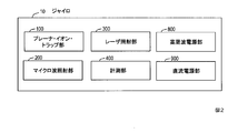
- FIG. The figure which shows the structural example of the gyro of this invention.
- FIG. 2 shows an example of the configuration of the gyro according to the present invention.
- the gyro 10 includes a planar ion trap unit 100, a microwave irradiation unit 200, a laser irradiation unit 300, a measurement unit 400, a high frequency power supply unit 800, and a DC power supply unit 900.
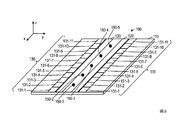
- FIG. 3 is a view showing a configuration example of a planar ion trap unit
- FIG. 4 is a view showing an example of arrangement of a planar ion trap unit, a microwave irradiation unit, a laser irradiation unit, and a measurement unit.
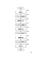
- FIG. 5 is a view showing a processing flow of the angle measurement method, and FIGS.
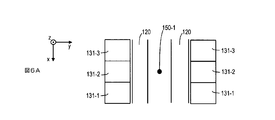
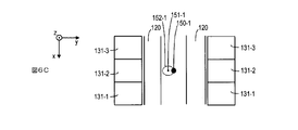
- FIG. 6A to 6C are views showing a state of movement of ions.
- FIG. 6A is a view showing a state in which the ions are at rest
- FIG. 6B is a view showing a state in which the ions vibrate in the x direction
- FIG. 6C is a view showing a state in which the ions circularly move.
- the planar ion trap portion 100 can form a plurality of ion traps for trapping one ion in the x direction on the substrate 110 with the normal direction of the surface as the z direction.
- the gyro 10 uses two energy levels in the ground state of the ion being captured.
- the ions ions which can be used at levels not affected by the magnetic field are suitable, for example, cadmium ions and ytterbium ions. However, it is not necessary to limit to these as long as the device is made insusceptible to the influence of the magnetic field, and other ions may be used.
- the planar ion trap portion 100 has two rf electrodes 120 and two DC electrode arrays 130 on a substrate 110.
- the two rf electrodes 120 are arranged on the substrate 110 in the x-direction so as to have a predetermined distance from each other.
- the predetermined interval is, for example, about 100 ⁇ m.
- the width of the rf electrode may be about several hundred ⁇ m to 1 mm.
- the two DC electrode arrays 130 are disposed on the substrate 110 in the x direction so as to sandwich the two rf electrodes 120.
- a high frequency power supply unit 800 is connected to the rf electrode 120 in order to capture ions in the yz direction.
- the DC electrode array 130 is composed of a plurality of DC electrodes 131. In FIG.
- the DC electrode array 130 is shown as an array of eleven DC electrodes 131-1,..., 11, and ions 150-1 are located at positions corresponding to the DC electrodes 131-2, 4, 6, 8 and 10. , ..., 5 are captured.
- the DC power supply unit 900 may apply a voltage to the DC electrodes 131-1, 3, 5, 7, 9, 11.
- the DC electrode array 130 may have at least five DC electrodes 131-1,..., 5 in the x direction. In order to increase the number of ions desired to be observed simultaneously, the number of DC electrodes may be increased. Further, in the example of FIG. 3, only one DC electrode is provided between ions, but a plurality of DC electrodes may be interposed.
- the planar ion trap unit 100 can move the center of the ion trap in the y direction.
- the DC power supply unit 900 may apply a bias voltage between the two DC electrode arrays 130.
- the trap center can be moved in the y direction. More specifically, the trap center can be shifted in the ⁇ y direction by applying a positive bias voltage to all of the DC electrodes 131-1,..., 11 constituting the DC electrode array 130 on the right side of FIG.
- a positive bias voltage may be applied to one DC electrode array 130 and a negative bias voltage may be applied to the other DC electrode array 130.
- the plurality of ion traps have an interval at which the trapped ions do not interfere with each other.
- a distance of about 1 mm is sufficient.
- the width of the DC electrodes 131-1, ..., 11 in the x direction may be about 0.5 mm.
- the planar ion trap unit 100, the microwave irradiation unit 200, the laser irradiation unit 300, and the measurement unit 400 may be arranged as shown in FIG.
- the microwave irradiation unit 200 irradiates the ions 150-1,..., 5 with the ⁇ / 2 pulse of the microwave from any direction.
- FIG. 4 shows an example of microwave irradiation from the y direction.
- the ⁇ / 2 pulse is a pulse whose existence probability of the internal state is half.
- the laser irradiation unit 300 irradiates two laser beams from opposite directions in the x direction, and changes the momentum of the ions 150-1, ..., 5 in the x direction.
- One of the two laser beams is light corresponding to one energy level in the ground state and the energy level in the excited state.
- the other of the two laser beams is light corresponding to one other energy level in the ground state and the energy level of the excited state.
- the two laser beams are predetermined laser pulses. More specifically, it is described in Non-Patent Document 2.
- the measuring unit 400 observes the internal state of the ions from the z direction, and measures the angle. For observation, a technique (fluorescence techniques) for detecting fluorescence from general ions may be used.
- FIGS. 6A-6C only the portion of the ions 150-1 is enlarged.
- 6A shows a state in which the ions are at rest
- FIG. 6B shows a state in which the ions vibrate in the x direction
- FIG. 6C shows a state in which the ions circularly move.
- the gyro 10 forms a plurality of ion traps, and sets the internal state of captured ions to a predetermined state (preparation step S110). Specifically, at least the internal state of the ion to be observed is aligned with one of the ground states. Generally, it is considered that all of the trapped ions are to be observed, but there is also the possibility of trapping another ion of interest, so here, at least as "at least the ions being observed” Explained. The same is true for the following.
- the microwave irradiation unit 200 irradiates microwaves of ⁇ / 2 pulse to at least ions to be observed (first microwave step S210). This step produces a superposition such that the two different internal states are at 50% each. Up to this step, the ions are at rest as shown in FIG. 6A.
- the laser irradiation unit 300 applies a laser pulse to at least ions to be observed to give momentum in the x direction (first laser step S310).
- a laser pulse irradiation of two laser pulses shown in Non-Patent Document 2 may be performed.
- the ions are kicked, momentum is given, and at the same time the internal state is changed. Also, the direction of momentum given is reversed depending on which of the two internal states is switched. Therefore, if the same two laser pulses are irradiated again after a half cycle of the vibration of ions, momentum is further given and the internal state is exchanged.
- the ions vibrate in the x direction as shown in FIG. 6B. Since the direction in which momentum is given by the internal state of ions is opposite, ions having the same internal state vibrate in the same phase, and different ions vibrate in the opposite phase.
- this ion travels in the negative direction of the x direction.
- the laser pulse changes to the ground state
- the laser pulse changes to the ground state
- e> in the stationary state is given momentum while moving in the opposite direction to the above.
- momentum can be given for each half cycle of vibration of the ion, and the same two laser pulses may be irradiated each time, so momentum can be given in a short time, and the configuration of the device Can be simplified.
- the DC power supply unit 900 applies a bias voltage between the two DC electrode arrays 130 of the planar ion trap unit 100, and at least the position of the trap center to be observed among the plurality of ion traps is in the y direction.
- To move a predetermined distance (trap center moving step S120). By this process, ions also vibrate in the y direction.
- FIG. 6C shows that the trap center 151-1 of the ion trap moves, and the ions 150-1 move in a circular orbit 152-1 indicated by a dotted line.
- the trap center moving step S120 is performed to perform the internal movement. Ions in the same state have the same rotation direction, and different ions have the opposite rotation direction.
- the gyro 10 waits for a time during which the ions rotate a predetermined number of times in this state (angle detection step S130). Since the time for one rotation of the ions is approximately 1 ⁇ s, it takes about 10 ms to make 10,000 rotations. In this case, the observation can be performed at intervals of about 20 ms, taking into consideration the time of other processes. If the number of ions to be captured is the number required for one measurement, the angle can be measured at intervals of 20 ms.
- the DC power supply unit 900 eliminates the bias voltage between the two DC electrode arrays 130 of the planar ion trap unit 100, at least the position of the trap center to be observed among the plurality of ion traps is determined.
- Restore trap center restoration step S140. By this process, as shown in FIG. 6B, the ions return to the state of vibrating in the x direction.
- the laser irradiation unit 300 irradiates at least the ions to be observed with a laser pulse to take away the momentum in the x direction (second laser step S320).
- the momentum is taken by irradiating a laser pulse (kicking ions) at a timing reverse to that of the first laser step S310. More specifically, the laser irradiation unit 300 performs the laser pulse a plurality of times every half cycle of the ion vibration from the time when the laser pulse is finally irradiated in the first laser step S310 and after an integer multiple of the cycle of the ion vibration. Can be irradiated. At this timing, it is possible to deprive the momentum of the ions with the same laser pulse as in the first laser step S310.
- the number of times of laser pulse irradiation may be the same as the number of times in the first laser step S310.
- g> is changed to the ground state
- the laser pulse is irradiated at this timing, it changes to the ground state
- the momentum for one irradiation of the laser pulse is taken away, and although it travels in the positive direction of the x direction, it decelerates.
- the ion travels in the negative direction of the x direction.
- the laser pulse changes to the ground state
- the momentum for one irradiation of the laser pulse is taken again, and although it travels in the negative direction of the x direction, it decelerates further. After a further half cycle, it proceeds in the positive direction of the x direction.
- the laser pulse is irradiated at this timing, it changes to the ground state
- the laser pulse irradiation is repeated every half period of the oscillation of the ion , Can take away the momentum of the ion. Ions whose ground state has been changed to
- the laser irradiation unit 300 Even when the laser pulse irradiation for each half cycle is not performed in the first laser step S310, since the last laser pulse for adding the momentum to the ions in the first laser step S310, the ion oscillation period After integer multiples, if the laser irradiation unit 300 repeatedly irradiates the laser pulse for each half cycle of the vibration of the ion, it is possible to deprive the momentum similarly.
- the microwave irradiator 200 irradiates microwaves of ⁇ / 2 pulse to at least ions to be observed (second microwave step S220).
- the measuring unit 400 observes an internal state of each ion and measures an angle (measuring step S410).
- a technique for detecting fluorescence from general ions may be used. Since the probability of the internal state can be known from the internal states of a plurality of ions, the angle may be measured based on this probability.
- the irradiation of microwaves and the irradiation of laser pulses can be simultaneously performed on a plurality of ions. And since internal states of a plurality of ions can be observed and angles can be measured from the results, measurement time can be shortened.
Landscapes
- Physics & Mathematics (AREA)
- Engineering & Computer Science (AREA)
- General Physics & Mathematics (AREA)
- Radar, Positioning & Navigation (AREA)
- Remote Sensing (AREA)
- Other Investigation Or Analysis Of Materials By Electrical Means (AREA)
Abstract
Description
Claims (4)
- x方向、y方向、z方向を互いに直交する方向とし、
1つのイオンを捕捉するイオントラップを、表面の法線方向をz方向とする基板上に形成するプレーナ・イオン・トラップ部と、
前記イオンに、マイクロ波のπ/2パルスを照射するマイクロ波照射部と、
前記イオンのx方向の運動量を変化させるためのレーザ照射部と、
前記イオンの内部状態を観測し、角度を計測する計測部と
を備え、
前記プレーナ・イオン・トラップ部は、
所定の間隔を有するようにx方向に前記基板上に配置された2つのrf電極と、
2つの前記rf電極を挟むようにx方向に前記基板上に配置された2つのDC電極列と
を有し、
前記DC電極列はx方向に少なくとも5個のDC電極を有し、
複数個のイオントラップを形成する場合は、捕捉するイオン同士が干渉しない間隔を有する
ことを特徴とするジャイロ。 - 請求項1記載のジャイロを用いた角度計測方法であって、
複数個の前記イオントラップを形成し、捕捉しているイオンの内部状態を所定の状態とする準備ステップと、
前記マイクロ波照射部が、前記イオンにπ/2パルスのマイクロ波を照射する第1マイクロ波ステップと、
前記レーザ照射部が、前記イオンにレーザパルスを照射してx方向の運動量を与える第1レーザステップと、
前記プレーナ・イオン・トラップ部の2つの前記DC電極列の間にバイアス電圧を与え、複数個の前記イオントラップのトラップ中心の位置をy方向に所定の距離移動させるトラップ中心移動ステップと、
前記イオンが所定の回数だけ回転する時間だけ待つ角度検出ステップと、
複数個の前記イオントラップのトラップ中心の位置を元の戻すトラップ中心復元ステップと、
前記レーザ照射部が、前記イオンにレーザパルスを照射してx方向の運動量を奪う第2レーザステップと、
前記マイクロ波照射部が、前記イオンにπ/2パルスのマイクロ波を照射する第2マイクロ波ステップと、
前記計測部が、前記イオンごとの内部状態を観測し、角度を計測する計測ステップ
を実行する角度計測方法。 - 請求項2記載の角度計測方法であって、
前記第1レーザステップでは、前記レーザ照射部が、前記イオンの振動の半周期ごとに複数回レーザパルスを照射する
ことを特徴とする角度計測方法。 - 請求項2または3記載の角度計測方法であって、
前記第2レーザステップでは、最後に前記イオンに運動量を付加するレーザを照射したときから前記イオンの振動の周期の整数倍後から、前記レーザ照射部が、前記イオンの振動の半周期ごとに複数回レーザパルスを照射する
ことを特徴とする角度計測方法。
Priority Applications (6)
| Application Number | Priority Date | Filing Date | Title |
|---|---|---|---|
| EP18868720.6A EP3683544B1 (en) | 2017-10-18 | 2018-07-25 | Gyroscope and angle measurement method |
| ES18868720T ES2902345T3 (es) | 2017-10-18 | 2018-07-25 | Giroscopio y método de medición de ángulo |
| US16/753,176 US11466987B2 (en) | 2017-10-18 | 2018-07-25 | Gyroscope and angle measurement method |
| JP2019549118A JP6860155B2 (ja) | 2017-10-18 | 2018-07-25 | ジャイロ、角度計測方法 |
| AU2018353571A AU2018353571B2 (en) | 2017-10-18 | 2018-07-25 | Gyroscope and angle measurement method |
| DK18868720.6T DK3683544T3 (da) | 2017-10-18 | 2018-07-25 | Gyroskop og fremgangsmåde til vinkelmåling |
Applications Claiming Priority (2)
| Application Number | Priority Date | Filing Date | Title |
|---|---|---|---|
| JP2017201527 | 2017-10-18 | ||
| JP2017-201527 | 2017-10-18 |
Publications (1)
| Publication Number | Publication Date |
|---|---|
| WO2019077829A1 true WO2019077829A1 (ja) | 2019-04-25 |
Family
ID=66173204
Family Applications (1)
| Application Number | Title | Priority Date | Filing Date |
|---|---|---|---|
| PCT/JP2018/027828 Ceased WO2019077829A1 (ja) | 2017-10-18 | 2018-07-25 | ジャイロ、角度計測方法 |
Country Status (7)
| Country | Link |
|---|---|
| US (1) | US11466987B2 (ja) |
| EP (1) | EP3683544B1 (ja) |
| JP (1) | JP6860155B2 (ja) |
| AU (1) | AU2018353571B2 (ja) |
| DK (1) | DK3683544T3 (ja) |
| ES (1) | ES2902345T3 (ja) |
| WO (1) | WO2019077829A1 (ja) |
Families Citing this family (9)
| Publication number | Priority date | Publication date | Assignee | Title |
|---|---|---|---|---|
| GB201802917D0 (en) | 2018-02-22 | 2018-04-11 | Micromass Ltd | Charge detection mass spectrometry |
| JP6600778B1 (ja) | 2018-07-24 | 2019-11-06 | 日本航空電子工業株式会社 | ジオイド測定方法、ジオイド測定装置、ジオイド推定装置、ジオイド計算用データ収集装置 |
| JP6713643B2 (ja) | 2018-12-07 | 2020-06-24 | 日本航空電子工業株式会社 | 原子線コリメーション方法、原子線コリメーター、原子干渉計、原子ジャイロスコープ |
| US11842891B2 (en) | 2020-04-09 | 2023-12-12 | Waters Technologies Corporation | Ion detector |
| CN113654545B (zh) * | 2021-07-22 | 2024-08-20 | 广州中国科学院工业技术研究院 | 基于离子阱芯片的陀螺仪及其转动测量方法 |
| WO2023111707A1 (en) | 2021-12-15 | 2023-06-22 | Waters Technologies Corporation | An inductive detector with integrated amplifier |
| CN114485545B (zh) * | 2022-01-20 | 2023-07-21 | 中国人民解放军海军航空大学青岛校区 | 一种高精度微波引导设备角度数据检测系统 |
| US12476104B2 (en) * | 2023-05-30 | 2025-11-18 | Infineon Technologies Austria Ag | Segmented movement control electrodes in ion traps |
| CZ2023439A3 (cs) | 2023-11-14 | 2024-12-18 | Univerzita Karlova | Systém napájecího obvodu planární Paulovy pasti |
Citations (2)
| Publication number | Priority date | Publication date | Assignee | Title |
|---|---|---|---|---|
| JP2000155028A (ja) * | 1998-11-19 | 2000-06-06 | Toyota Motor Corp | プラズマ式ヨーレートセンサ |
| JP2007085957A (ja) * | 2005-09-26 | 2007-04-05 | Fumihito Kato | ジャイロセンサ |
Family Cites Families (10)
| Publication number | Priority date | Publication date | Assignee | Title |
|---|---|---|---|---|
| US7180078B2 (en) * | 2005-02-01 | 2007-02-20 | Lucent Technologies Inc. | Integrated planar ion traps |
| GB201204817D0 (en) * | 2012-03-19 | 2012-05-02 | Shimadzu Corp | A method of processing image charge/current signals |
| GB201304491D0 (en) * | 2013-03-13 | 2013-04-24 | Shimadzu Corp | A method of processing image charge/current signals |
| KR101482440B1 (ko) * | 2013-10-14 | 2015-01-15 | 에스케이텔레콤 주식회사 | 이온 트랩 장치 및 그 제작 방법 |
| KR101725793B1 (ko) * | 2014-10-30 | 2017-04-12 | 에스케이 텔레콤주식회사 | 이온 트랩 구조를 관통하는 레이저 사용을 위한 mems 기반 3차원 이온트랩 장치 및 그 제작 방법 |
| KR101725788B1 (ko) * | 2014-10-31 | 2017-04-12 | 에스케이 텔레콤주식회사 | 절연층 노출을 방지한 이온 트랩 장치 및 그 제작 방법 |
| US10553414B2 (en) * | 2015-06-26 | 2020-02-04 | Honeywell International Inc. | Apparatus and method for trapping multiple ions generated from multiple sources |
| US11049713B1 (en) * | 2020-05-12 | 2021-06-29 | Honeywell International Inc. | Deterministic reshaping and/or reordering of groups of atomic objects within an atomic object confinement apparatus |
| US11025228B1 (en) * | 2020-05-12 | 2021-06-01 | Honeywell International Inc. | Dynamic noise shaping filters and corresponding methods |
| US11876092B2 (en) * | 2020-07-31 | 2024-01-16 | Quantinuum Llc | Ion trap apparatus with integrated switching apparatus |
-
2018
- 2018-07-25 DK DK18868720.6T patent/DK3683544T3/da active
- 2018-07-25 EP EP18868720.6A patent/EP3683544B1/en active Active
- 2018-07-25 US US16/753,176 patent/US11466987B2/en active Active
- 2018-07-25 AU AU2018353571A patent/AU2018353571B2/en active Active
- 2018-07-25 JP JP2019549118A patent/JP6860155B2/ja active Active
- 2018-07-25 WO PCT/JP2018/027828 patent/WO2019077829A1/ja not_active Ceased
- 2018-07-25 ES ES18868720T patent/ES2902345T3/es active Active
Patent Citations (2)
| Publication number | Priority date | Publication date | Assignee | Title |
|---|---|---|---|---|
| JP2000155028A (ja) * | 1998-11-19 | 2000-06-06 | Toyota Motor Corp | プラズマ式ヨーレートセンサ |
| JP2007085957A (ja) * | 2005-09-26 | 2007-04-05 | Fumihito Kato | ジャイロセンサ |
Non-Patent Citations (7)
| Title |
|---|
| J. MIZRAHIC. SENKOB. NEYENHUISK. G. JOHNSONW. C. CAMPBELLC.W. S. CONOVERC. MONROE: "Ultrafast Spin-Motion Entanglement and Interferometry with a Single Atom", PHYSICAL REVIEW LETTERS, PRL, vol. 110, 2013, pages 203001 |
| See also references of EP3683544A4 |
| TANAKA UTAKO ET AL.: "Design of a surface electrode trap for parallel ion strings", JOURNAL OF PHYSICS B: ATOMIC, MOLECULAR AND OPTICAL PHYSICS, vol. 47, no. 3, 16 January 2014 (2014-01-16), pages 35301, XP020256997, ISSN: 0953-4075, Retrieved from the Internet <URL:http://iopscience.iop.org/article/10.1088/0953-4075/47/3/035301/pdf> [retrieved on 20181011], DOI: 10.1088/0953-4075/47/3/035301 * |
| U. TANAKAK. MASUDAY. AKIMOTOK. KODAY. IBARAKIS. URABE: "Micromotion compensation in a surface electrode trap by parametric excitation of trapped ions", APPL PHYS B, vol. 107, 2012, pages 907 - 912, XP035077399, DOI: 10.1007/s00340-011-4762-2 |
| UTAKO TANAKAKENSUKE SUZUKIYUKI IBARAKISHINJI URABE: "Design of a surface electrode trap for parallel ion strings", JOURNAL OF PHYSICS B: ATOMIC, MOLECULAR AND OPTICAL PHYSICS, vol. 47, 2014, pages 035301 |
| W C CAMPBELLP HAMILTON: "Rotation sensing with trapped ions", JOURNAL OF PHYSICS B: ATOMIC, MOLECULAR AND OPTICAL PHYSICS, vol. 50, 2017, pages 064002 |
| W. C. CAMPBELL ET AL.: "Rotation sensing with trapped ions", JOURNAL OF PHYSICS B: ATOMIC, MOLECULAR AND OPTICAL PHYSICS, vol. 50, no. 6, 23 February 2017 (2017-02-23), pages 64002, XP020314174, ISSN: 0953-4075, DOI: 10.1088/1361-6455/aa5a8f * |
Also Published As
| Publication number | Publication date |
|---|---|
| DK3683544T3 (da) | 2022-03-14 |
| JPWO2019077829A1 (ja) | 2020-11-05 |
| AU2018353571B2 (en) | 2021-08-26 |
| AU2018353571A1 (en) | 2020-04-23 |
| EP3683544A1 (en) | 2020-07-22 |
| US20200300630A1 (en) | 2020-09-24 |
| EP3683544A4 (en) | 2020-11-04 |
| EP3683544B1 (en) | 2021-12-22 |
| JP6860155B2 (ja) | 2021-04-14 |
| ES2902345T3 (es) | 2022-03-28 |
| US11466987B2 (en) | 2022-10-11 |
Similar Documents
| Publication | Publication Date | Title |
|---|---|---|
| JP6860155B2 (ja) | ジャイロ、角度計測方法 | |
| JP7416431B2 (ja) | 複数のキュービット種を有する量子ネットワークノードおよびプロトコル | |
| Gong et al. | Asymmetric attosecond photoionization in molecular shape resonance | |
| Wals et al. | Observation of Rydberg wave packet dynamics in a Coulombic and magnetic field | |
| Hansen et al. | Time-Resolved Photoelectron Angular Distributions from Strong-Field Ionization<? format?> of Rotating Naphthalene Molecules | |
| JP7712263B2 (ja) | 連続積分フィルタによる複数のコントローラビームの高速強度安定化 | |
| Bounouar et al. | Path-controlled time reordering of paired photons in a dressed three-level cascade | |
| Song et al. | Femtosecond photoelectron imaging on pyrazine: Spectroscopy of 3s and 3p Rydberg states | |
| Colgan et al. | Two-photon double ionization of the hydrogen molecule | |
| NL2033936B1 (en) | Quantum logic gate for a trapped ion quantum computer | |
| Doering et al. | Quantum-projection-noise-limited interferometry with coherent atoms in a Ramsey-type setup | |
| Haruyama et al. | First-principles molecular-dynamics simulation of biphenyl under strong laser pulses by time-dependent density-functional theory | |
| Low et al. | Quantum logic operations and algorithms in a single 25-level atomic qudit | |
| Ohmura et al. | Phase-sensitive molecular ionization induced by a phase-controlled two-color laser field in methyl halides | |
| Saito et al. | Generation of a single-ion large oscillator | |
| Yatsuhashi et al. | Coulomb explosion of dichloroethene geometric isomers at 1 PW cm–2 | |
| Picón et al. | Auger-induced charge migration | |
| Sakemi et al. | Orientation dependence in multichannel dissociative ionization of OCS molecules | |
| Matsuda et al. | Time-resolved laser Coulomb explosion imaging using few-cycle intense laser pulses: Application to exploding CS2 in highly charged states | |
| Schöffler et al. | Matter wave optics perspective at molecular photoionization: K-shell photoionization and Auger decay of N2 | |
| Shimizu et al. | Photon generation by laser-compton scattering using an optical resonant cavity at the KEK-ATF electron ring | |
| Karski et al. | Direct observation and analysis of spin dependent transport of single atoms in a 1d optical lattice | |
| Brandstätter | Integration of fiber mirrors and ion traps for a high-fidelity quantum interface | |
| O'Neal et al. | Tracking charge migration with attosecond X-ray pulses from a free-electron laser | |
| Yamazaki et al. | Strong variation of the phase lag in the vicinity of autoionizing resonances |
Legal Events
| Date | Code | Title | Description |
|---|---|---|---|
| 121 | Ep: the epo has been informed by wipo that ep was designated in this application |
Ref document number: 18868720 Country of ref document: EP Kind code of ref document: A1 |
|
| ENP | Entry into the national phase |
Ref document number: 2019549118 Country of ref document: JP Kind code of ref document: A |
|
| ENP | Entry into the national phase |
Ref document number: 2018868720 Country of ref document: EP Effective date: 20200414 |
|
| NENP | Non-entry into the national phase |
Ref country code: DE |
|
| ENP | Entry into the national phase |
Ref document number: 2018353571 Country of ref document: AU Date of ref document: 20180725 Kind code of ref document: A |