WO2019077834A1 - 積層複合部材の形状最適化解析方法及び形状最適化解析装置 - Google Patents
積層複合部材の形状最適化解析方法及び形状最適化解析装置 Download PDFInfo
- Publication number
- WO2019077834A1 WO2019077834A1 PCT/JP2018/028379 JP2018028379W WO2019077834A1 WO 2019077834 A1 WO2019077834 A1 WO 2019077834A1 JP 2018028379 W JP2018028379 W JP 2018028379W WO 2019077834 A1 WO2019077834 A1 WO 2019077834A1
- Authority
- WO
- WIPO (PCT)
- Prior art keywords
- block model
- optimization analysis
- shape
- model
- analysis
- Prior art date
- Legal status (The legal status is an assumption and is not a legal conclusion. Google has not performed a legal analysis and makes no representation as to the accuracy of the status listed.)
- Ceased
Links
Images










Classifications
-
- G—PHYSICS
- G06—COMPUTING OR CALCULATING; COUNTING
- G06F—ELECTRIC DIGITAL DATA PROCESSING
- G06F30/00—Computer-aided design [CAD]
- G06F30/10—Geometric CAD
- G06F30/15—Vehicle, aircraft or watercraft design
-
- B—PERFORMING OPERATIONS; TRANSPORTING
- B62—LAND VEHICLES FOR TRAVELLING OTHERWISE THAN ON RAILS
- B62D—MOTOR VEHICLES; TRAILERS
- B62D65/00—Designing, manufacturing, e.g. assembling, facilitating disassembly, or structurally modifying motor vehicles or trailers, not otherwise provided for
-
- G—PHYSICS
- G06—COMPUTING OR CALCULATING; COUNTING
- G06F—ELECTRIC DIGITAL DATA PROCESSING
- G06F30/00—Computer-aided design [CAD]
- G06F30/10—Geometric CAD
- G06F30/17—Mechanical parametric or variational design
-
- G—PHYSICS
- G06—COMPUTING OR CALCULATING; COUNTING
- G06F—ELECTRIC DIGITAL DATA PROCESSING
- G06F30/00—Computer-aided design [CAD]
- G06F30/20—Design optimisation, verification or simulation
-
- G—PHYSICS
- G06—COMPUTING OR CALCULATING; COUNTING
- G06F—ELECTRIC DIGITAL DATA PROCESSING
- G06F30/00—Computer-aided design [CAD]
- G06F30/20—Design optimisation, verification or simulation
- G06F30/23—Design optimisation, verification or simulation using finite element methods [FEM] or finite difference methods [FDM]
-
- G—PHYSICS
- G06—COMPUTING OR CALCULATING; COUNTING
- G06F—ELECTRIC DIGITAL DATA PROCESSING
- G06F2111/00—Details relating to CAD techniques
- G06F2111/06—Multi-objective optimisation, e.g. Pareto optimisation using simulated annealing [SA], ant colony algorithms or genetic algorithms [GA]
-
- G—PHYSICS
- G06—COMPUTING OR CALCULATING; COUNTING
- G06F—ELECTRIC DIGITAL DATA PROCESSING
- G06F2113/00—Details relating to the application field
- G06F2113/26—Composites
-
- Y—GENERAL TAGGING OF NEW TECHNOLOGICAL DEVELOPMENTS; GENERAL TAGGING OF CROSS-SECTIONAL TECHNOLOGIES SPANNING OVER SEVERAL SECTIONS OF THE IPC; TECHNICAL SUBJECTS COVERED BY FORMER USPC CROSS-REFERENCE ART COLLECTIONS [XRACs] AND DIGESTS
- Y02—TECHNOLOGIES OR APPLICATIONS FOR MITIGATION OR ADAPTATION AGAINST CLIMATE CHANGE
- Y02T—CLIMATE CHANGE MITIGATION TECHNOLOGIES RELATED TO TRANSPORTATION
- Y02T10/00—Road transport of goods or passengers
- Y02T10/10—Internal combustion engine [ICE] based vehicles
- Y02T10/40—Engine management systems
Definitions
- the present invention relates to an analysis of shape optimization method and shape optimization analysis apparatus for layered composite members, and in particular, a part of a structural body is a material property.
- the present invention relates to a laminated composite member in which a plurality of layers different from each other are laminated, and a shape optimization analysis method and a shape optimization analysis device of the laminated composite member for determining an optimum shape of the laminated composite member.
- shape optimization is assumed to be a predetermined shape, for example, a T-shape in advance, and is not to obtain the optimum shape on the premise of the predetermined shape, but to analyze without assuming the predetermined shape. It means to find the optimum shape that satisfies the condition.
- CAE analysis computer aided engineering
- topology optimization is particularly focused.
- a design space of a certain size is provided, a three-dimensional element is incorporated in the design space, a given condition is satisfied, and a minimum number of three-dimensional elements are required.
- it is a method of determining the optimum shape that satisfies the condition. Therefore, in topology optimization, a method is used in which constraints are directly imposed on three-dimensional elements forming a design space, and direct loads are applied.
- Patent Document 1 discloses a method for topology optimization of components of a complex structure.
- Patent Document 1 relates to a mathematical operation method and physical system related to optimization analysis by topology optimization, and it does not deal with the problem such as optimization of thin plate structure as described above. Does not give a solution for
- the object of conventional shape optimization has been metal materials such as steel, aluminum alloy (Al alloy), magnesium alloy, etc. as shown in Patent Document 2, for example.
- a composite member referred to as a “laminated composite member” in the present application
- resin resin
- FRP Fiber-Reinforced Plastics
- the present invention has been made in view of the above problems, and an object of the present invention is to improve the rigidity by using a laminated composite member for a part of a structure that is a vehicle body. It is an object of the present invention to provide a shape optimization analysis method and a shape optimization analysis device for laminated composite members to be obtained.
- a method of shape optimization analysis of a laminated composite member wherein the laminated composite member is a two-dimensional element or a part of a vehicle body structure model consisting of a planar element and a three-dimensional element.
- the shape optimization analysis method of a laminated composite member according to the second aspect of the present invention models a part of a structural model of a vehicle body consisting of a planar element or a planar element and a three-dimensional element with a laminated composite member, and performs the modeling Optimization analysis of the shape of the laminated composite member, the computer performing the following steps, and laminating a plurality of layers to be portions to be optimized in the structure model of the vehicle body.
- Design space setting step set as design space, and different material characteristics are provided for each set design space to generate a layered block model composed of three-dimensional elements, and a layered block model generated for each design space is combined Forming a laminated block model consisting of the three-dimensional element, and generating the laminated block model, and using the generated laminated block model as a structure of the vehicle body
- a coupling process step coupled to a part of the model, and an analysis analysis step for performing optimization analysis with the laminated block model as an analysis object of optimization, input analysis conditions, and determining an optimum shape of the laminated block model; including.
- the shape optimization analysis method of a layered composite member according to the present invention is the shape optimization analysis method of a layered composite member according to the first aspect of the present invention, wherein the layered block model is composed of three-dimensional elements and plural different material characteristics. Are connected using rigid elements (beam elements) or plane elements, or share and connect nodes of the plurality of layers. I assume.
- the shape optimization analysis method of a layered composite member according to the present invention is the shape optimization analysis method of a layered composite member according to the second aspect of the present invention, wherein the layered block model is generated in three or more design spaces. It is characterized in that a layered block model composed of elements is connected using a rigid element, a beam element or a plane element, or nodes of the layered block model are shared and connected.
- the method for shape optimization analysis of a laminated composite member according to the present invention is the method for shape optimization analysis of a laminated composite member according to the present invention, wherein the laminated block model is a pentahedron to octahedron and two mutually parallel planes. And at least one pair of three-dimensional elements.
- the shape optimization analysis method for laminated composite members according to the present invention is the shape optimization analysis method for laminated composite members according to the present invention, wherein the laminated block model is set by the design space in a part of the structural model of the vehicle body. It is characterized in that a surface parallel to the surrounding surface is generated so as to have the largest area.
- the shape optimization analysis method of a layered composite member according to the present invention is the shape optimization analysis method of a layered composite member according to the present invention, wherein the layered block model is a plane element or a three-dimensional element of a part of a structure model of the vehicle body. Placing nodal points at the joints with the three-dimensional elements and using a hexahedral solid element as the three-dimensional elements of the layered block model and generating the three-dimensional elements so as to be stacked along a plane including the nodal points arranged at the joints It features.
- the shape optimization analysis method of a laminated composite member according to the present invention is the shape optimization analysis method of a laminated composite member according to the present invention, wherein the optimization analysis step is discretization using optimization parameters in the optimization analysis. It is characterized by doing.
- the shape optimization analysis method of a laminated composite member according to the present invention is characterized in that, in the shape optimization analysis method of a laminated composite member according to the present invention, the optimization analysis step performs optimization analysis by topology optimization. Do.
- a shape optimization analysis apparatus for a laminated composite member, which models a part of a structural element of a vehicle body consisting of a planar element or a planar element and a three-dimensional element with the laminated composite member.
- a design space setting unit for setting a part to be an optimization target in the structure model of the vehicle body as a design space, and performing the optimization analysis of the shape of the laminated composite member.
- a stacked block model generation unit configured to generate a stacked block model in which a plurality of layers having three-dimensional elements and different material properties are stacked; a combined processing unit configured to combine the generated stacked block model with a part of the vehicle body structure model;
- An analysis analysis unit that inputs analysis conditions, performs optimization analysis on the stacked block model as an analysis target of optimization, and obtains an optimal shape of the stacked block model Includes an analysis unit), the.
- the shape optimization analysis device for a laminated composite member models a portion of a structural element of a vehicle body consisting of a planar element or a planar element and a three-dimensional element with a laminated composite member and performs the modeling
- a design space setting unit configured to perform optimization analysis of the shape of the laminated composite member, and setting a part to be an optimization target in the structure model of the vehicle body as a plurality of design spaces layered in layers
- Layered block model which gives different material characteristics for each set design space and generates a layered block model consisting of three-dimensional elements, and combines layered block models generated for each of the design spaces to generate stacked block model consisting of the three-dimensional elements
- the shape optimization analysis apparatus for laminated composite members according to the present invention is the shape optimization analysis apparatus for laminated composite members according to the first aspect of the present invention, wherein the laminated block model is composed of three-dimensional elements and has a plurality of different material characteristics.
- the layers are connected by using a rigid element, a beam element or a plane element, or by sharing and connecting the nodes of the plurality of layers.
- the shape optimization analysis device for laminated composite members according to the present invention is the shape optimization analysis device for laminated composite members according to the second aspect of the present invention, wherein the laminated block model is a three-dimensional shape generated for each of a plurality of design spaces.
- a layered block model consisting of elements is characterized in that it is connected using a rigid element, a beam element or a plane element, or connected by sharing nodes of the layered block model.
- the shape optimization analysis apparatus for laminated composite members according to the present invention is the shape optimization analysis apparatus for laminated composite members according to the present invention, wherein the laminated block model is a pentahedron or more and an octahedron or less and two parallel planes. And at least one pair of three-dimensional elements.
- the shape optimization analysis device for laminated composite members according to the present invention is the shape optimization analysis device for laminated composite members according to the present invention, wherein the laminated block model is set by the design space in a part of the structure model of the vehicle body. It is characterized in that a surface parallel to the surrounding surface is generated so as to have the largest area.
- the shape optimization analysis apparatus for laminated composite members according to the present invention is the shape optimization analysis apparatus for laminated composite members according to the present invention, wherein the laminated block model is a planar element or a three-dimensional element of a part of a structural model of the vehicle body. Placing nodal points at the joints with the three-dimensional elements and using a hexahedral solid element as the three-dimensional elements of the layered block model and generating the three-dimensional elements so as to be stacked along a plane including the nodal points arranged at the joints It features.
- the shape optimization analysis device for laminated composite members according to the present invention is the shape optimization analysis device for laminated composite members according to the present invention, wherein the optimization analysis unit performs discretization with optimization parameters in optimization analysis. It is characterized by
- the shape optimization analysis device for laminated composite members according to the present invention is characterized in that, in the shape optimization analysis device for laminated composite members according to the present invention, the optimization analysis unit performs optimization analysis by topology optimization. Do.
- the present invention when an external force acts on a structure that is a vehicle body, it is possible to obtain the optimal shape of a laminated composite member that is a part of the vehicle body, and improve the predetermined performance of the structure. In addition, it is possible to contribute to weight reduction of the structure while maintaining the predetermined performance.
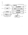
- FIG. 1 is a block diagram of a shape optimization analysis apparatus for laminated composite members according to an embodiment of the present invention.
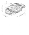
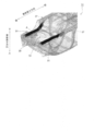
- FIG. 2 is a diagram for explaining a vehicle body model as an analysis target of shape optimization as an example and a design space set in the vehicle body model according to the embodiment.
- FIG. 3 is a diagram for explaining a design space set in a vehicle body model in the embodiment (part 1).
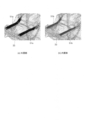
- FIG. 4 is a diagram for explaining a design space set in the vehicle body model in the embodiment (part 2 (a) outer layer, (b) inner layer).
- FIG. 5 is a cross-sectional view of a design space set in the vehicle body model in the embodiment.
- FIG. 6 is a diagram for explaining the load condition input in the analysis process of optimization in the embodiment (torsion stiffness).
- FIG. 7 is a diagram for explaining the load conditions input in the analysis process of optimization in the embodiment (lateral bending stiffness).
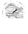
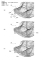
- FIG. 8 is a diagram for explaining an optimal shape obtained by analysis processing of optimization for a rear cross member in the embodiment.
- FIG. 9 is a flow chart showing a flow of processing of the shape optimization analysis method of the laminated composite member according to the embodiment of the present invention.
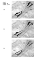
- FIG. 10 is a diagram showing an analysis result of an optimal shape obtained by optimization analysis for the rear cross member in the example (Case 1, outer layer portion: steel sheet, inner layer portion: steel).
- FIG. 11 is a view showing an analysis result of an optimum shape obtained by optimization analysis for the rear cross member in the example (Case 2, outer layer portion: aluminum alloy, inner layer portion: steel) .
- FIG. 12 is a diagram showing an analysis result of an optimal shape obtained by optimization analysis for the rear cross member in the example (Case 3, outer layer portion: steel, inner layer portion: Al alloy).
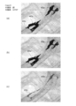
- FIG. 13 is a diagram showing an analysis result of an optimal shape obtained by optimization analysis for the rear cross member in the example (Case 4, outer layer portion: CFRP, inner layer portion: steel).
- FIG. 14 is a diagram showing an analysis result of an optimal shape obtained by optimization analysis for the rear cross member in the example (Case 5, outer layer portion: steel, inner layer portion: CFRP).
- FIG. 15 is a diagram showing an analysis result of an optimal shape obtained by optimization analysis for the rear cross member in the example (Case 6, outer layer portion: steel, inner layer portion: GFRP).
- FIG. 16 is a diagram showing an analysis result of an optimal shape obtained by optimization analysis for the rear cross member in the example (Case 7, outer layer portion: steel, inner layer portion: resin).
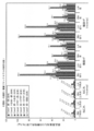
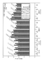
- FIG. 17 shows the improvement in rigidity (improvement rate of stiffness) of a vehicle body model in which rear cross members of an optimal shape obtained by optimization analysis by changing combinations of materials of laminated block models in the embodiment are combined.
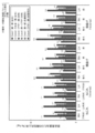
- Is a graph showing the influence of FIG. 18 is a graph showing an influence on a rigidity improvement rate per part weight of a vehicle body model obtained by combining rear cross members of an optimum shape obtained by optimization analysis by changing a combination of materials of laminated block models in the embodiment. is there.
- FIG. 17 shows the improvement in rigidity (improvement rate of stiffness) of a vehicle body model in which rear cross members of an optimal shape obtained by optimization analysis by changing combinations of materials of laminated block models in the embodiment are combined.
- Is a graph showing the influence of FIG. 18 is a graph showing an influence on a rigidity improvement
- FIG. 19 is a diagram showing a design space in which rear side members of a vehicle body model are set in the embodiment (part 1).
- FIG. 20 is a diagram showing a design space set for the rear side member of the vehicle body model in the embodiment (part 2; (a) outer layer; (b) inner layer).
- FIG. 21 is a cross-sectional view of a design space in which the rear side member of the vehicle body model is set in the embodiment.
- FIG. 22 is a diagram showing an analysis result of an optimal shape obtained by optimization analysis for the rear side member in the example (Case 1, outer layer portion: steel, inner layer portion: steel).
- FIG. 23 is a diagram showing an analysis result of an optimal shape obtained by optimization analysis for the rear side member in the example (Case 2, outer layer portion: Al alloy, inner layer portion: steel).
- FIG. 24 is a diagram showing an analysis result of an optimal shape obtained by optimization analysis for the rear side member in the example (Case 4, outer layer portion: CFRP, inner layer portion: steel).
- FIG. 25 is a diagram showing an analysis result of an optimal shape obtained by optimization analysis for the rear side member in the example (Case 5, outer layer portion: steel, inner layer portion: CFRP).
- FIG. 26 is a diagram showing an analysis result of an optimum shape obtained by optimization analysis for the rear side member in the example (Case 1, restriction condition: volume restriction ratio of each of outer layer portion and inner layer portion is 10% or less ).
- FIG. 27 is a diagram showing an analysis result of an optimal shape obtained by optimization analysis for the rear side member in the example (Case 4, constraints: volume constraint ratio of each of the outer layer portion and the inner layer portion (constraints of volume fraction) 10% or less).
- FIG. 28 is a graph showing the influence on the rigidity improvement rate of a vehicle body model in which rear side members of the optimum shape obtained by optimization analysis by changing the combination of materials of the laminated block model for the rear side members in the embodiment are obtained It is.
- FIG. 29 shows the rigidity improvement per part (parts) weight of the vehicle body model combining the rear side members of the optimum shape obtained by the optimization analysis by changing the combination of materials of the laminated block model for the rear side members in the embodiment. It is a graph which shows the influence on a rate.
- a structure model of a vehicle body (hereinafter simply referred to as a "structure model") targeted by the present invention. ) Will be described.
- the structure model is a model of the structure using planar elements and / or three-dimensional elements when connecting a laminated composite member which is a material different from the structure to a part of the structure.
- a vehicle body model 31 shown in FIG. 2 is targeted as an example of the structure model.
- the vehicle body model 31 is composed of a plurality of parts such as an automobile body frame component (automotive body frame member) and a chassis component (Chassis component), and each component of the vehicle body model 31 is a plane element and / or a three-dimensional element. It is modeled by an element. Further, information on the elements (planar elements and three-dimensional elements) of each part constituting the vehicle body model 31, the material characteristics (materials), and the like are stored in the structure model file 21 (see FIG. 1).
- shape optimization analysis apparatus 1 for laminated composite members according to the present embodiment (hereinafter simply referred to as “shape optimization analysis apparatus 1”) will be described below based on FIGS. 1 to 8.
- the shape optimization analysis apparatus 1 When the shape optimization analysis apparatus 1 according to the present embodiment couples a laminated composite member which is a material different from a part of the structure to a part of a structure which is a car body and stiffens the structure, The optimum shape of the laminated composite member is determined.
- the shape optimization analysis apparatus 1 according to the present embodiment is configured by a computer such as a PC (personal computer), and includes a display device 3, an input device 5, and a storage. It has a device (memory storage) 7, a working data memory 9 and an arithmetic processing unit 11.
- the display device 3, the input device 5, the storage device 7, and the work data memory 9 are connected to the arithmetic processing unit 11, and their respective functions are executed according to an instruction from the arithmetic processing unit 11.
- a rear cross member (design space 41) which is a part of the vehicle body model 31 shown in FIG.
- the case of finding the optimum shape of the member will be described as an example.
- the display device 3 is used to display analysis results and the like, and is configured of a liquid crystal monitor or the like.
- the input device 5 is used for a display instruction of the structure model file 21 or an operator's condition input and the like, and is configured by a keyboard, a mouse or the like.
- the storage device 7 is used to store various files such as the structure model file 21 and the like, and is configured by a hard disk or the like.
- the work data memory 9 is used for temporary storage and calculation of data used by the calculation processing unit 11, and is configured by a RAM (Random Access Memory) or the like.
- the arithmetic processing unit 11 includes a design space setting unit 13, a stacked block model generation unit 15, a coupling processing unit 17, and an optimization analysis unit 19, as shown in FIG. Processing device). These units function when the CPU executes a predetermined program. The functions of the above-described units in the arithmetic processing unit 11 will be described below.
- the design space setting unit 13 sets a part to be an optimization target to a part of a structure model as a design space.
- the design space setting unit 13 deletes a part to be optimized in the structure model, and sets a design space in the deleted part.
- FIG. 2 shows an example in which a design space 41 of the rear cross member is set in a part of a vehicle body model 31 as a structure model.
- the rear cross member originally included in the vehicle body model 31 is deleted, and a design space 41 is set in the deleted portion.
- the upper surface side in the vehicle height direction is joined to the floor panel 33, and the left and right ends in the vehicle width direction are connected to the rear side member 35.
- the floor panel 33 and the rear side member 35 are left without being deleted when the.
- the design space 41 should be set as a space surrounded by the surface of the shape along the floor panel 33, the surface of the shape along the rear side member 35, and the surface extended to the limit of the designable range.
- the designable range can be set as appropriate based on, for example, the shape of the original rear cross member and the gap with other parts around the rear cross member.
- the design space setting unit 13 sets the design space 41 by deleting the rear cross member which is a part of the vehicle body model 31 acquired from the structure model file 21. 41 may be preset when generating the vehicle body model 31. In this case, the design space setting unit 13 may have a function of generating the vehicle body model 31.
- the stacked block model generation unit 15 generates a stacked block model 43 in which a plurality of layers having three-dimensional elements and different material characteristics are stacked in the set design space 41.
- the layered block model 43 is a model of the layered composite member, and is an object to be subjected to analysis processing for optimization.
- the stacked block model generation unit 15 can generate the stacked block model 43 having an arbitrary shape and a size that enters the design space 41. Then, in the generation of the laminated block model 43, the laminated block model generation unit 15 first sets a plurality of layers composed of solid elements, and connects the plurality of layers using rigid elements, beam elements or planar elements, or The plurality of layers are connected and stacked in layers by sharing nodes of three-dimensional elements of the plurality of layers.
- the three-dimensional element used in the layered block model 43 is preferably a polyhedron having a facet number of not less than pentahedron and not more than an octahedron, and is preferably composed of a three-dimensional element having at least one pair of two faces parallel to each other.
- the portion forming the design space 41 is a layered member such as a layered composite member, it can be reflected in the shape of the layered composite member when the optimization analysis process is performed on the layered block model 43. It is desirable that an optimal shape be sought. Such a requirement can be easily satisfied by using a three-dimensional element having at least one pair of pentahedrons to octahedrons and at least one pair of parallel parallel faces.
- the present invention does not exclude the use of less than pentahedral or more than octahedral steric elements, such as tetrahedral steric elements.
- FIGS. 3 to 5 show an example in which the stacked block model 43 is generated in the design space 41 shown in FIG. 3 shows the vehicle body model 31 from the lower side in the vehicle height direction, FIG. 4 shows the outer layer portion 43a and the inner layer portion 43b of the laminated block model 43, and FIG. 5 shows the laminated block model 43.
- 3 is a cross-sectional view orthogonal to the vehicle body width direction in FIG.
- the laminated block model 43 is generated from the outer layer portion 43a and the inner layer portion 43b different in material property, and the outer layer portion 43a and the inner layer portion 43b are stacked in layers.
- the outer layer portion 43a and the inner layer portion 43b are respectively formed of three-dimensional elements, and in the present embodiment, the outer layer portion 43a and the inner layer portion 43b are coupled so as to share the nodes of the three-dimensional elements.
- Examples of material properties set for the outer layer portion 43a and the inner layer portion 43b of the layered block model 43 include Young's modulus, Poisson's ratio, specific gravity, and the like.
- the material of the laminated block model 43 is By giving an angle of principal axis giving the in-plane anisotropy of the material properties of each of the outer layer portion 43a and the inner layer portion 43b, and setting the value of the material property corresponding to the main axis angle, the in-plane difference is obtained. You can set the directionality. In addition, it is also possible to set the principal axis angle for each layer of the outer layer portion 43a and the inner layer portion 43b.
- the laminated block model generation unit 15 is a laminated block so as to subdivide the three-dimensional element along the surface around which the design space 41 in the vehicle body model 31 is set and parallel to the surface having the largest area of the design space 41.
- model 43 is generated.
- the peripheral surface in which the design space 41 is set is the surface of the part (rear cross member in the present embodiment) at the portion where the design space 41 is to be set, and has the largest area of the design space.
- a surface means the thing of the largest area among the said surrounding surfaces.
- the surface along the floor panel 33 to which the rear cross member joins and the rear side member are set as the peripheral face on which the design space 41 is set.
- the layered block model generation unit 15 sets a three-dimensional element constituting the layered block model 43 as a hexahedron three-dimensional element, and arranges a node of the hexahedron three-dimensional element at a joint portion with a plane element or three-dimensional element
- the layered block model 43 may be generated so as to stack hexahedral solid elements along a plane including the nodes disposed at the coupling portion.
- the layered block model generation unit 15 sets a node of the plane element of the floor panel 33 as a coupling portion with the layered block model 43.
- the stacked block model 43 may be generated by stacking hexahedron solid elements along a plane including the nodes.
- the coupling processing unit 17 performs processing for coupling the generated layered block model 43 to another portion of the vehicle body model 31.
- a rigid element, a plane element, and a beam element can be used to connect the laminated block model 43 and the vehicle body model 31.
- connection between the laminated block model 43 and the vehicle body model 31 reflects the original connection between the portion removed as the design space 41 and the vehicle body model 31 so that the load is accurately transmitted from the vehicle body model 31 to the laminated block model 43 It is preferable to make it
- the optimization analysis unit 19 applies analysis conditions to the vehicle body model 31 to which the stacked block model 43 is coupled, and performs optimization analysis for obtaining an optimal shape of the stacked block model 43.
- the analysis conditions include a load condition that gives a position to which a load is applied and a constraint position, and an objective condition and a constraint condition that are set according to the purpose and the constraint of the optimization analysis.
- FIG. 6 and 7 show an example of the load condition.
- FIG. 6 is for the case of performing an optimization analysis for torsional stiffness and FIG. 7 for the lateral bending stiffness.
- load input points are set at two positions on the rear side of the vehicle body model 31 respectively at the left and right suspension attachment parts, and the vehicle height is set at each load input point.
- a load (1000 N) was applied upward and downward in the longitudinal direction.
- load input points are set at four positions on the rear side suspension mounting portion of the vehicle body model 31, and the vehicle width at each load input point.
- a predetermined load 1000 N was applied to the right of the direction.
- the restraint position is not set, but in the present embodiment, the coordinates of the inertial force acting on the vehicle body model 31 by the inertia relief method.
- the optimization analysis is performed on the assumption that the vehicle body model 31 is supported at the reference support point.
- the load conditions given by the optimization analysis unit 19 are not limited to the above, and the position where the load is input to the vehicle body model 31, the position where the displacement is restrained, etc. are appropriately set according to the purpose of the optimization analysis. May be
- the objective conditions in the optimization analysis include, for example, minimization of total strain energy in the vehicle body model 31, minimization of displacement, minimization of stress, maximization of rigidity, and the like.
- a constraint in the optimization analysis there is, for example, a volume constraint rate of the stacked block model 43 to be an object of the optimization analysis, and a plurality of constraints can be set.
- the volume restriction rate may be individually given to the entire stacked block model 43 or each layer of the stacked block model 43 (for example, each layer of the outer layer portion 43a and the inner layer portion 43b shown in FIGS. 4 and 5). it can.
- topology optimization can be applied to the optimization analysis processing by the optimization analysis unit 19.
- it is preferable to discretize by giving a penalty coefficient as an optimization parameter. It is preferable to limit the penalty coefficient in discretization to two or more values, or a value 3 to 20 times the size of the reference three-dimensional element. By giving the penalty coefficient and discretizing it, it is possible to reflect the laminated block model obtained as the optimum shape on the structure shape of the thin plate.
- the optimization analysis unit 19 may perform topology optimization as described above, or may perform optimization processing by another calculation method. For example, a commercially available finite element method may be used. You can also use the analysis software that you
- FIG. 8 shows an example of the optimum shape 45 obtained by applying topology optimization to the optimization analysis unit 19 with the rear cross member as the optimization target.
- the optimum shape 45 is obtained by remaining and erasing three-dimensional elements for each of the outer layer portion 43a and the inner layer portion 43b of the laminated block model 43 so as to satisfy the above analysis conditions (load condition, objective condition and constraint condition). As shown in FIG. 8, it comprises an optimum shape outer layer 45a and an optimum shape inner layer 45b.
- the load is transmitted from the vehicle body model 31 to the stacked block model 43 via the portion coupled to the vehicle body model 31. That is, the load is transmitted from the vehicle body model 31 to the stacked block model 43, and the stacked block model 43 is deformed in the analysis process of optimization by the optimization analysis unit 19 to change the direction of the load, etc. The direction of the load and the like are reflected to finally obtain an optimum shape 45 whose shape is optimized.
- one design space 41 is set by the design space setting unit 13, and the stacked block model 43 is generated by generating a plurality of layers in the set design space 41.
- the generation of the stacked block model 43 is not limited to this.
- the design space setting unit 13 sets a portion to be an optimization target of the vehicle body model 31 as a plurality of design spaces to be laminated in layers, and the laminated block model generation unit 15
- a plurality of layered block models (corresponding to the outer layer portion 43a and the inner layer portion 43b shown in FIG. 4 and FIG. 5) are generated by giving different material characteristics to each set design space, and A plurality of layered block models generated in may be combined to generate a layered block model consisting of the three-dimensional elements.
- the design space setting unit 13 deletes the part to be optimized from a part of the structure model, sets one design space in the deleted part, and stacks the design space in layers. Setting a plurality of design spaces by newly setting other design spaces so as to be layered in two or more design spaces after dividing or setting one design space Can.
- the layered block model generation unit 15 combines a plurality of layered block models by sharing nodes of layered block models formed of three-dimensional elements generated for each of the plurality of set design spaces, or a plurality of layered block models Can be combined using a rigid element, a beam element, or a planar element to generate a layered block model layered.
- shape optimization analysis method a shape optimization analysis method of the laminated composite member according to the present embodiment (hereinafter simply referred to as “shape optimization analysis method”) will be described.
- the shape optimization analysis method according to the present embodiment a part of the structure model is modeled by a laminated composite member, and optimization analysis of the shape of the modeled laminated composite member is performed.
- the shape optimization analysis method according to the present embodiment includes a design space setting step S1, a stacked block model generation step S3, a coupling processing step S5, and an optimization analysis step S7. It is Hereinafter, each step described above will be described for the case where the vehicle body model 31 shown in FIG. 2 is taken as an example of the structure model.
- the shape optimization analysis method according to the present embodiment can execute each of the above steps using the shape optimization analysis device 1 (see FIG. 1) configured by a computer.
- Design space setting step S1 As shown in FIG. 2, a portion to be optimized in the vehicle body model 31 is set as a design space 41 to be layered, and in the shape optimization analysis apparatus 1, the design is performed.
- the space setting unit 13 performs this.
- ⁇ stacked block model generation step >>
- a plurality of layers (for example, the outer layer portion 43a and the inner layer portion 43b shown in FIGS. 4 and 5) are formed of three-dimensional elements and different material characteristics in the design space 41 set in the design space setting step S1.
- the laminated block model generation unit 15 generates a plurality of layers in which three-dimensional elements are stacked in layers, and connects the plurality of layers using rigid elements, beam elements or plane elements,
- the stacked block model 43 is generated by sharing and connecting the nodes of the three-dimensional elements of the plurality of layers.
- the three-dimensional element used in the layered block model 43 is a polyhedron having a number of faces of not less than five faces and not more than eight faces, and is composed of a three-dimensional element having at least one pair of two faces parallel to each other.
- the laminated block model generation unit 15 sets material characteristics (Young's modulus, Poisson's ratio, specific gravity, etc.) for each layer.
- material characteristics Young's modulus, Poisson's ratio, specific gravity, etc.
- the principal axis angle giving the in-plane anisotropy is The value of the material property corresponding to the spindle angle may be set. In this case, it is also possible to set the spindle angle for each of a plurality of layers in the stacked block model 43.
- the laminated block is divided along the surface around which the design space 41 in the vehicle body model 31 is set and parallel to the surface having the largest area of the design space 41.
- model 43 is generated.
- the peripheral surface in which the design space 41 is set is the surface of the component at the portion where the design space is to be set, and the surface having the largest area of the design space is the surface of the peripheral surfaces. It says the one with the largest area.
- the coupling processing step S5 is a step of coupling the lamination block model 43 generated in the lamination block model generation step S3 to the vehicle body model 31, and in the shape optimization analysis device 1, the lamination block model generation unit 15 performs it.
- the optimization analysis step S7 inputs an analysis condition to the vehicle body model 31 to which the laminated block model 43 is coupled in the coupling processing step S5, and the optimum shape 45 (FIG. 8) in which the shape of the laminated block model 43 is optimized.
- the optimization analysis unit 19 performs this optimization analysis.
- the optimization analysis unit 19 sets, as analysis conditions for optimization analysis, a load condition that gives a position at which a load is applied to the vehicle body model 31 and the purpose of optimization analysis. Target conditions and constraints to be imposed when performing optimization analysis.
- topology optimization can be applied to the optimization analysis in the optimization analysis step S7. Furthermore, when applying a density method in topology optimization, it is preferable to set the penalty coefficient of the element to 2 or more to perform discretization.
- analysis processing of optimization can be applied by another calculation method, and for example, finite elements that are commercially available can be used as analysis processing of optimization. You can use analysis software using.
- one design space 41 is set in the design space setting step S1, and a plurality of layers are generated in the set design space 41 in the stacked block model generation step S3, so that the material characteristics differ.
- a plurality of layers generate the stacked block model 43
- the mode of generating the stacked block model 43 is not limited to this.
- the design space setting step S1 a plurality of design spaces for laminating the portions to be optimized in the vehicle body model 31 in layers are set, and laminated block model generation step S3.
- different material characteristics are given to each set design space to generate a layered block model (for example, corresponding to the outer layer portion 43a and the inner layer portion 43b shown in FIG. 4 and FIG. 5)
- the layered block model generated each time may be combined to generate a layered block model 43 composed of the three-dimensional elements.
- a method similar to that of the design space setting unit 13 described above can be used.
- the laminated composite member when stiffening a part of a structure that is a vehicle body using the laminated composite member, the laminated composite member is The optimum shape of the member can be determined accurately. Furthermore, by using the laminated composite member having the optimal shape, it is possible to reduce the weight of the structure. The weight reduction and the rigidity improvement effect of the structure using the laminated composite member of the optimum shape will be specifically described in Examples described later.
- the structure is a car body of a car
- the rear cross member which is a part of the car body is an analysis target of shape optimization
- the present invention is not limited to the rear cross member but will be described later.
- the rear side member of a car or other parts may be the analysis target of shape optimization, and there is no particular limitation on the structure or parts to be analyzed.
- each of the rear cross member and the rear side member which are parts constituting the vehicle body model 31 shown in FIG. 2 is modeled by laminated composite members, and optimization analysis is performed to obtain the optimum shape.
- the vehicle body model 31 is a model of the vehicle body using plane elements and / or three-dimensional elements, and the material of the vehicle body model 31 is steel.
- a design space is set in part of the acquired vehicle body model 31, and a layered block model is generated in the set design space.
- a design space is set, and a stacked block model in which two layers having different material properties are stacked in the set design space is generated.
- FIG. 2 shows a design space 41 set in the vehicle body model 31 for the rear cross member.
- the rear cross member (not shown) originally included in the vehicle body model 31 is joined while the floor panel 33 and the rear side member 35 are left.
- the cross member is removed to form a space surrounded by a surface having a shape along the floor panel 33, a surface along the rear side member 35, and a surface determined based on the shape of the original rear cross member.
- a stacked block model 43 in which the outer layer portion 43a and the inner layer portion 43b are layered in layers is generated in the set design space 41 (see FIGS. 3 to 5).
- the outer layer portion 43a and the inner layer portion 43b are formed so as to stack three layers of hexahedral solid elements, respectively, and the thickness of each of the outer layer portion 43a and the inner layer portion 43b is 5 mm.
- the outer layer part 43a and the inner layer part 43b were connected by sharing the node of the hexahedron solid element which comprises each.
- CFRP carbon fiber reinforced plastics
- GFRP carbon fiber reinforced plastics
- glass fiber reinforced plastics glass fiber reinforced plastics
- the laminated block model 43 in which the material characteristics were set was coupled to the vehicle body model 31, and the optimization analysis for determining the optimum shape of the laminated block model 43 was performed.
- the laminated block model 43 and the vehicle body model 31 are coupled by the three-dimensional elements of the laminated block model 43.
- load conditions and optimization analysis conditions are given as analysis conditions to the vehicle body model 31 to which the stacked block model 43 is coupled.
- the load conditions are the rear suspension for the case where the optimization analysis is performed for the torsional stiffness shown in FIG. 6 and the case where the optimization analysis is performed for the lateral bending stiffness shown in FIG. 7.
- a load of 1000 N was applied to the position and direction of each arrow shown in the drawing which is the mounting portion.
- the minimum of the sum of strain energy is given as the target condition
- the volume restriction rate of the laminated block model 43 is given as the restriction condition.
- optimization analysis was performed in the case where the volume restriction rate of the entire stacked block model 43 was 20% or less.
- topology optimization is used for optimization analysis, the objective condition is to minimize the distortion energy sum, and the constraint is to be the volume constraint rate of the stacked block model 43.
- the volume restriction rate was set for the entire stacked block model 43.
- optimization analysis was performed by changing the combination of materials of the outer layer portion and the inner layer portion of the layered block model, and the optimum shape of the layered composite member according to the difference of the combination of materials was examined.
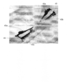
- 10 to 16 show analysis results of the optimum shape 45 obtained by performing optimization analysis by changing the combination of materials of the stacked block model 43 with the rear cross member as an analysis target of optimization.
- FIG. 10 to 16 are optimized by changing the combination of the material of the outer layer portion 43a and the inner layer portion 43b (FIG. 4) (hereinafter referred to as “(material of outer layer portion) ⁇ (material of inner layer portion)”) It is the analysis result, and the combination of the material in each figure is “Steel-Steel” (Case 1) in FIG. 10, “Al alloy-Steel” (Case 2) in FIG. 11, and “Steel-Al alloy” in FIG. (Case 3), FIG. 13 is “CFRP-Steel” (Case 4), FIG. 14 is “Steel-CFRP” (Case 5), FIG. 15 is “Steel-GFRP” (Case 6), FIG. 16 is “Steel -Resin "(Case 7).
- Case 1 has the same material (steel) in outer layer portion 43a and inner layer portion 43b
- Case 2 to Case 7 are different in outer layer portion 43a and inner layer portion 43b although they are not included in the present invention. Since the material is set, it is included in the present invention.
- the restriction condition in the optimization analysis is set to a volume restriction ratio of 20% or less with respect to the entire stacked block model 43. 10A to 16B, (a) shows the remaining state in which the optimum shape outer layer 45a and the optimum shape inner layer 45b are combined, and (b) shows only the optimum shape outer layer 45a, (c ) Is a display of only the optimum shape inner layer 45b.
- “twist” and “lateral bending” on the horizontal axis respectively represent the cases where the load conditions shown in FIG. 6 and FIG. 7 are given, and “RH” and “LH” in each load condition. It shows a load input position (see FIGS. 6 and 7).
- “reverse” of “reverse” and “reverse” of the horizontal axis is symmetrical to the load condition of “torsion” and “lateral bend” in each load input position.
- the “rigidity improvement rate” on the vertical axis is a value based on the stiffness of the vehicle body model 31 from which the rear cross member targeted for optimization analysis is removed, and the stiffness is each load It calculated by dividing the displacement at the input point by the value of the input load. Further, the vertical axis in FIG. 18 is obtained by dividing the calculated rigidity improvement rate by the weight of the part to be optimized.
- FIGS. 17 and 18 the load conditions on the horizontal axis and the bar graphs for each load input point are shown in the order of the conditions (Case 1 to Case 7) shown in the legend in the figure (figures described later) 28 and FIG. 29).
- the result of high weight efficiency was obtained by making the material of the optimum shape outer layer portion 45a lightweight and highly rigid CFRP. That is, when the laminated composite member is applied to the rear cross member of the vehicle body, and the weight of the laminated composite member is reduced while maintaining the rigidity of the original vehicle body, the laminated composite member using CFRP as the material of the outer layer portion It was suggested that the most weight reduction could be achieved when used.
- the rear side members constituting the vehicle body model 31 are also modeled by laminated composite members, and optimization analysis is performed to obtain the optimum shape. Also in the case of performing the optimization analysis for the rear side member, first, the design space was set in the vehicle body model 31. In the case of the rear side member, the rear bumper portion 39 to which the rear side member originally included in the vehicle body model 31 was joined is deleted, and the surface of the shape along the floor panel 33 and the tip portion in the vehicle length direction are connected.
- a stacked block model 51 in which the outer layer portion 51 a and the inner layer portion 51 b are layered in layers is generated in the set design space.
- the outer layer portion 51a and the inner layer portion 51b are generated so as to stack three layers of hexahedron solid elements, respectively, as in the case of the laminated block model 43 for rear cross members described above, and the outer layer portion 51a and the inner layer
- the thickness of the portion 51 b was 5 mm in all cases.
- the outer layer part 51a and the inner layer part 51b were connected by sharing the node of the hexahedron solid element which comprises each.
- the volume constraint rate of the entire stacked block model 43 is set to 20% or less, and the outer layer portion 51a and the inner layer portion 51b of the stacked block model 51 are each 10% individually.
- the optimization analysis was performed for both of the following cases.
- FIG. 22 to 25 show combinations of materials of the outer layer portion 51a and the inner layer portion 51b of the layered block model 51 (hereinafter referred to as “( The material of part)-((material of inner layer)) is changed, and the combination of materials in each figure is shown in Fig. 22 as “steel-steel” (Case 1) and Fig. 23 as " Al alloy-steel (Case 2), FIG. 24 shows “CFRP-Steel” (Case 4), and FIG. 25 shows “Steel-CFRP” (Case 5).
- FIG. 26 and FIG. 27 give a volume restriction rate of 10% or less to each of the outer layer portion 51a and the inner layer portion 51b of the laminated block model 51 as a constraint condition in the optimization analysis, and the materials of the outer layer portion 51a and the inner layer portion 51b
- the combination of “(material of outer layer portion) ⁇ (material of inner layer portion)” in FIG. 26 is “steel-steel” (Case 1), and FIG. 27 is “CFRP-steel” (Case 4).
- the volume restriction rate which is the constraint is satisfied regardless of the Young's modulus of the outer layer 51a.
- the material of the optimally shaped inner layer portion 53b is increased.
- FIG. 28 and FIG. 29 show a car body model 31 in which rear side members composed of laminated composite members of the optimum shape 53 obtained by optimization analysis under various conditions in which combinations of materials of the laminated block model 51 and constraints are changed Improvement rate of
- the “twist” and “lateral bending” and “RH” and “LH” of the horizontal axis in FIGS. 28 and 29 and the “rigidity improvement rate” and the “rigidity improvement rate per part weight” of the vertical axis are all The same as FIG. 17 and FIG.
- the “rigidity improvement rate” is a value based on the rigidity of the vehicle body model 31 before the rear side member (steel plate thickness of 1.8 mm) targeted for optimization analysis is removed. Further, in the legends of FIG. 28 and FIG. 29, “whole” sets the volume restriction rate for the entire laminated block model 51 as a restriction condition, and “each layer individually” indicates the outer layer portion 51 a of the laminated block model 51 as a restriction condition. And that the volume restriction rate is set for each of the inner layer portions 51b.
- the rigidity improvement rate is better when the volume constraint rate is imposed on the entire laminated block model, compared with the case where the volume constraint rate is imposed individually on the outer layer portion and the inner layer portion.
- the result is higher. This is considered to be because selecting a more efficient material layout can be achieved by giving the volume restriction rate to the entire laminated block model, for example, more material can be left in the outer layer portion.
- the rigidity improvement rate per part weight shown in FIG. 29 is the same as the result of the above-mentioned rear cross member (FIG. 18), the material of the optimum shape outer layer 53a is lightweight and high rigidity CFRP In the case, the result with the highest weight efficiency was obtained. That is, as in the case of the above-mentioned rear cross member, when the laminated composite member is applied to the rear side member of the vehicle body, the most weight reduction can be achieved when the laminated composite member using CFRP as the material of the outer layer portion is used. It was suggested.
- a shape optimization analysis method and shape optimization of the laminated composite member for finding an optimum shape of the laminated composite member An analysis device can be provided.
Landscapes
- Engineering & Computer Science (AREA)
- Physics & Mathematics (AREA)
- Geometry (AREA)
- Theoretical Computer Science (AREA)
- General Physics & Mathematics (AREA)
- Evolutionary Computation (AREA)
- General Engineering & Computer Science (AREA)
- Computer Hardware Design (AREA)
- Computational Mathematics (AREA)
- Pure & Applied Mathematics (AREA)
- Mathematical Optimization (AREA)
- Mathematical Analysis (AREA)
- Aviation & Aerospace Engineering (AREA)
- Automation & Control Theory (AREA)
- Chemical & Material Sciences (AREA)
- Manufacturing & Machinery (AREA)
- Mechanical Engineering (AREA)
- Combustion & Propulsion (AREA)
- Transportation (AREA)
- Body Structure For Vehicles (AREA)
- Automobile Manufacture Line, Endless Track Vehicle, Trailer (AREA)
- Testing Of Devices, Machine Parts, Or Other Structures Thereof (AREA)
Abstract
Description
構造体モデルは、構造体の一部に該構造体と異なる材料である積層複合部材を結合するに際し、平面要素及び/又は立体要素を用いて前記構造体をモデル化したものである。本実施の形態では、構造体モデルの一例として、図2に示す車体モデル31を対象としている。
次に、本実施の形態に係る積層複合部材の形状最適化解析装置1(以下、単に「形状最適化解析装置1」という)の構成について、図1乃至図8に基づいて以下に説明する。
表示装置3は、解析結果の表示等に用いられ、液晶モニター等で構成される。
入力装置5は、構造体モデルファイル21の表示指示や操作者の条件入力等に用いられ、キーボードやマウス等で構成される。
記憶装置7は、構造体モデルファイル21等の各種ファイルの記憶等に用いられ、ハードディスク等で構成される。
作業用データメモリ9は、演算処理部11で使用するデータの一時保存や演算に用いられ、RAM(Random Access Memory)等で構成される。
演算処理部11は、図1に示すように、設計空間設定部13と、積層ブロックモデル生成部15と、結合処理部17と、最適化解析部19を有し、PC等のCPU(中央演算処理装置)によって構成される。これらの各部は、CPUが所定のプログラムを実行することによって機能する。演算処理部11における上記の各部の機能を以下に説明する。
設計空間設定部13は、構造体モデルの一部に最適化の対象となる部分を設計空間として設定するものである。設計空間設定部13は、構造体モデルにおいて最適化の対象とする一部分を削除し、該削除した部分に設計空間を設定する。
積層ブロックモデル生成部15は、設定した設計空間41に、立体要素からなり材料特性の異なる複数の層が積層した積層ブロックモデル43を生成するものである。ここで、積層ブロックモデル43は、積層複合部材をモデル化したものであり、最適化の解析処理を行う対象となる。
結合処理部17は、生成した積層ブロックモデル43を、車体モデル31における他の部位に結合する処理を行うものである。積層ブロックモデル43と車体モデル31との結合には、剛体要素、平面要素、梁要素を用いることができる。
最適化解析部19は、積層ブロックモデル43を結合した車体モデル31に対して解析条件を与え、積層ブロックモデル43の最適な形状を求める最適化解析を行うものである。解析条件としては、荷重を付加する位置や拘束位置を与える荷重条件と、最適化解析の目的や制約に応じて設定する目的条件(objective condition)及び制約条件(constraint condition)とがある。
次に、本実施の形態に係る積層複合部材の形状最適化解析方法(以下、単に「形状最適化解析方法」という)について説明する。
設計空間設定ステップS1は、図2に示すように、車体モデル31における最適化の対象となる部分を層状に積層する設計空間41として設定するステップであり、形状最適化解析装置1においては、設計空間設定部13が行う。
積層ブロックモデル生成ステップS3は、設計空間設定ステップS1において設定した設計空間41に、立体要素からなり材料特性の異なる複数の層(例えば、図4及び図5に示す外層部43a及び内層部43b)が積層した積層ブロックモデル43を生成するステップであり、形状最適化解析装置1においては、積層ブロックモデル生成部15が行う。
結合処理ステップS5は、積層ブロックモデル生成ステップS3において生成した積層ブロックモデル43を車体モデル31に結合するステップであり、形状最適化解析装置1においては、積層ブロックモデル生成部15が行う。
最適化解析ステップS7は、結合処理ステップS5において積層ブロックモデル43を結合した車体モデル31に対して解析条件を入力し、積層ブロックモデル43の形状が最適化された最適形状45(図8)を求める最適化解析を行うステップであり、形状最適化解析装置1においては、最適化解析部19が行う。

3 表示装置
5 入力装置
7 記憶装置
9 作業用データメモリ
11 演算処理部
13 設計空間設定部
15 積層ブロックモデル生成部
17 結合処理部
19 最適化解析部
21 構造体モデルファイル
31 車体モデル
33 フロアパネル
35 リアサイドメンバ
37 サイドシル
39 リアバンパ部
41 リアクロスメンバの設計空間
43 積層ブロックモデル
43a 外層部
43b 内層部
45 最適形状
45a 最適形状外層部
45b 最適形状内層部
51 積層ブロックモデル
51a 外層部
51b 内層部
53 最適形状
53a 最適形状外層部
53b 最適形状内層部
Claims (18)
- 平面要素、又は平面要素と立体要素からなる車体の構造体モデルの一部分を、積層複合部材でモデル化し、該モデル化した積層複合部材の形状の最適化解析を行う積層複合部材の形状最適化解析方法であって、コンピュータが以下の各ステップを行うものであり、
前記車体の構造体モデルにおける最適化の対象となる一部分を設計空間として設定する設計空間設定ステップと、
該設定した設計空間に、立体要素からなり材料特性の異なる複数の層が積層した積層ブロックモデルを生成する積層ブロックモデル生成ステップと、
該生成した積層ブロックモデルを前記車体の構造体モデルの一部分に結合する結合処理ステップと、
解析条件を入力し、前記積層ブロックモデルを最適化の解析対象として最適化解析を行い、前記積層ブロックモデルの最適な形状を求める最適化解析ステップと、
を含むことを特徴とする積層複合部材の形状最適化解析方法。 - 平面要素、又は平面要素と立体要素からなる車体の構造体モデルの一部分を、積層複合部材でモデル化し、該モデル化した積層複合部材の形状の最適化解析を行う積層複合部材の形状最適化解析方法であって、コンピュータが以下の各ステップを行うものであり、
前記車体の構造体モデルにおける最適化の対象となる一部分を層状に積層する複数の設計空間として設定する設計空間設定ステップと、
該設定した設計空間毎に異なる材料特性を与えて立体要素からなる層状ブロックモデルを生成し、該設計空間毎に生成した層状ブロックモデルを結合して前記立体要素からなる積層ブロックモデルを生成する積層ブロックモデル生成ステップと、
該生成した積層ブロックモデルを前記車体の構造体モデルに結合する結合処理ステップと、
解析条件を入力し、前記積層ブロックモデルを最適化の解析対象として最適化解析を行い、前記積層ブロックモデルの最適な形状を求める最適化解析ステップと、
を含むことを特徴とする積層複合部材の形状最適化解析方法。 - 前記積層ブロックモデルは、立体要素からなり材料特性の異なる複数の層を、剛体要素、梁要素若しくは平面要素を用いて連結、又は、前記複数の層の節点を共有させて連結してなることを特徴とする請求項1記載の積層複合部材の形状最適化解析方法。
- 前記積層ブロックモデルは、複数の設計空間毎に生成した立体要素からなる層状ブロックモデルを剛体要素、梁要素若しくは平面要素を用いて連結、又は、前記層状ブロックモデルの節点を共有させて連結してなることを特徴とする請求項2記載の積層複合部材の形状最適化解析方法。
- 前記積層ブロックモデルは、五面体以上八面体以下であって互いに平行な2面を少なくとも一組有する立体要素からなることを特徴とする請求項1乃至4のいずれか一項に記載の積層複合部材の形状最適化解析方法。
- 前記積層ブロックモデルは、前記車体の構造体モデルの一部分における前記設計空間が設定された周囲の面と平行になる面が最大面積となるように生成することを特徴とする請求項1乃至5のいずれか一項に記載の積層複合部材の形状最適化解析方法。
- 前記積層ブロックモデルは、前記車体の構造体モデルの一部分の平面要素又は立体要素との結合部に節点を配置し、前記積層ブロックモデルの立体要素として六面体立体要素を用いると共に、前記結合部に配置された節点を含む平面に沿うように立体要素を積み上げるように生成することを特徴とする請求項1乃至6のいずれか一項に記載の積層複合部材の形状最適化解析方法。
- 前記最適化解析ステップは、最適化解析において最適化パラメータで離散化を行うことを特徴とする請求項1乃至7のいずれか一項に記載の積層複合部材の形状最適化解析方法。
- 前記最適化解析ステップは、トポロジー最適化による最適化解析を行うことを特徴とする請求項1乃至8のいずれか一項に記載の積層複合部材の形状最適化解析方法。
- 平面要素、又は平面要素と立体要素からなる車体の構造体モデルの一部分を、積層複合部材でモデル化し、該モデル化した積層複合部材の形状の最適化解析を行う積層複合部材の形状最適化解析装置であって、
前記車体の構造体モデルにおける最適化の対象となる一部分を設計空間として設定する設計空間設定部と、
該設定した設計空間に、立体要素からなり材料特性の異なる複数の層が積層した積層ブロックモデルを生成する積層ブロックモデル生成部と、
該生成した積層ブロックモデルを前記車体の構造体モデルの一部分に結合する結合処理部と、
解析条件を入力し、前記積層ブロックモデルを最適化の解析対象として最適化解析を行い、前記積層ブロックモデルの最適な形状を求める最適化解析部と、
を備えたことを特徴とする積層複合部材の形状最適化解析装置。 - 平面要素、又は平面要素と立体要素からなる車体の構造体モデルの一部分を、積層複合部材でモデル化し、該モデル化した積層複合部材の形状の最適化解析を行う積層複合部材の形状最適化解析装置であって、
前記車体の構造体モデルにおける最適化の対象となる一部分を層状に積層する複数の設計空間として設定する設計空間設定部と、
該設定した設計空間毎に異なる材料特性を与えて立体要素からなる層状ブロックモデルを生成し、該設計空間毎に生成した層状ブロックモデルを結合して前記立体要素からなる積層ブロックモデルを生成する積層ブロックモデル生成部と、
該生成した積層ブロックモデルを前記車体の構造体モデルの一部分に結合する結合処理部と、
解析条件を入力し、前記積層ブロックモデルを最適化の解析対象として最適化解析を行い、前記積層ブロックモデルの最適な形状を求める最適化解析部と、
を備えたことを特徴とする積層複合部材の形状最適化解析装置。 - 前記積層ブロックモデルは、立体要素からなり材料特性の異なる複数の層を、剛体要素、梁要素若しくは平面要素を用いて連結、又は、前記複数の層の節点を共有させて連結したものであることを特徴とする請求項10記載の積層複合部材の形状最適化解析装置。
- 前記積層ブロックモデルは、複数の設計空間毎に生成した立体要素からなる層状ブロックモデルを、剛体要素、梁要素若しくは平面要素を用いて連結、又は、前記層状ブロックモデルの節点を共有させて連結したものであることを特徴とする請求項11記載の積層複合部材の形状最適化解析装置。
- 前記積層ブロックモデルは、五面体以上八面体以下であって互いに平行な2面を少なくとも一組有する立体要素からなることを特徴とする請求項10乃至13のいずれか一項に記載の積層複合部材の形状最適化解析装置。
- 前記積層ブロックモデルは、前記車体の構造体モデルの一部分における前記設計空間が設定された周囲の面と平行になる面が最大面積となるように生成することを特徴とする請求項10乃至14のいずれか一項に記載の積層複合部材の形状最適化解析装置。
- 前記積層ブロックモデルは、前記車体の構造体モデルの一部分の平面要素又は立体要素との結合部に節点を配置し、前記積層ブロックモデルの立体要素として六面体立体要素を用いると共に、前記結合部に配置された節点を含む平面に沿うように立体要素を積み上げるように生成することを特徴とする請求項10乃至15のいずれか一項に記載の積層複合部材の形状最適化解析装置。
- 前記最適化解析部は、最適化解析において最適化パラメータで離散化を行うことを特徴とする請求項10乃至16のいずれか一項に記載の積層複合部材の形状最適化解析装置。
- 前記最適化解析部は、トポロジー最適化による最適化解析を行うことを特徴とする請求項10乃至17のいずれか一項に記載の積層複合部材の形状最適化解析装置。
Priority Applications (5)
| Application Number | Priority Date | Filing Date | Title |
|---|---|---|---|
| CN201880067279.1A CN111226219B (zh) | 2017-10-17 | 2018-07-30 | 层叠复合构件的形状最优化解析方法及形状最优化解析装置 |
| EP18868721.4A EP3699786B1 (en) | 2017-10-17 | 2018-07-30 | Layered composite member shape optimization analyzing method and shape optimization analyzing device |
| KR1020207010530A KR102398560B1 (ko) | 2017-10-17 | 2018-07-30 | 적층 복합 부재의 형상 최적화 해석 방법 및 형상 최적화 해석 장치 |
| MX2020003972A MX2020003972A (es) | 2017-10-17 | 2018-07-30 | Metodo de analisis de optimizacion de forma de miembros compuestos de capas y dispositivo de analisis de optimizacion. |
| US16/753,562 US11494534B2 (en) | 2017-10-17 | 2018-07-30 | Layered-composite-member shape optimization analysis method and optimization analysis device |
Applications Claiming Priority (2)
| Application Number | Priority Date | Filing Date | Title |
|---|---|---|---|
| JP2017-200795 | 2017-10-17 | ||
| JP2017200795A JP6497426B1 (ja) | 2017-10-17 | 2017-10-17 | 積層複合部材の形状最適化解析方法及び装置 |
Publications (1)
| Publication Number | Publication Date |
|---|---|
| WO2019077834A1 true WO2019077834A1 (ja) | 2019-04-25 |
Family
ID=66092670
Family Applications (1)
| Application Number | Title | Priority Date | Filing Date |
|---|---|---|---|
| PCT/JP2018/028379 Ceased WO2019077834A1 (ja) | 2017-10-17 | 2018-07-30 | 積層複合部材の形状最適化解析方法及び形状最適化解析装置 |
Country Status (7)
| Country | Link |
|---|---|
| US (1) | US11494534B2 (ja) |
| EP (1) | EP3699786B1 (ja) |
| JP (1) | JP6497426B1 (ja) |
| KR (1) | KR102398560B1 (ja) |
| CN (1) | CN111226219B (ja) |
| MX (1) | MX2020003972A (ja) |
| WO (1) | WO2019077834A1 (ja) |
Cited By (1)
| Publication number | Priority date | Publication date | Assignee | Title |
|---|---|---|---|---|
| CN110781603A (zh) * | 2019-11-05 | 2020-02-11 | 上海波客实业有限公司 | 一种汽车碳纤维增强复合材料加强件设计方法 |
Families Citing this family (6)
| Publication number | Priority date | Publication date | Assignee | Title |
|---|---|---|---|---|
| JP7099562B1 (ja) * | 2021-01-27 | 2022-07-12 | Jfeスチール株式会社 | 車体の軽量化方法及び装置 |
| CN114741846B (zh) * | 2022-03-15 | 2023-12-01 | 中国民航大学 | 一种超低热膨胀复合材料支撑结构的设计方法 |
| CN114626274A (zh) * | 2022-04-01 | 2022-06-14 | 福建工程学院 | 基于拓扑优化公交车体侧围与顶盖间连接纵梁设计方法 |
| CN114633803B (zh) * | 2022-04-21 | 2022-12-23 | 东风商用车有限公司 | 基于材料拓扑的一体铸造式平衡悬架横梁及其制造方法 |
| KR102897194B1 (ko) * | 2022-12-16 | 2025-12-05 | 현대제철 주식회사 | 연속섬유복합소재가 적용된 차량의 구조해석 장치 및 방법 |
| CN116681357B (zh) * | 2023-07-28 | 2023-10-27 | 济南市莱芜区综合检验检测中心 | 基于人工智能的食品质量分析系统及方法 |
Citations (5)
| Publication number | Priority date | Publication date | Assignee | Title |
|---|---|---|---|---|
| JP2010250818A (ja) | 2009-04-10 | 2010-11-04 | Livermore Software Technology Corp | トポロジー最適化における工業製品の最適設計を得る方法 |
| JP2013025533A (ja) | 2011-07-20 | 2013-02-04 | Jfe Steel Corp | 形状最適化解析方法及び装置 |
| JP2014149732A (ja) * | 2013-02-01 | 2014-08-21 | Jfe Steel Corp | 形状最適化解析方法及び装置 |
| JP2017058907A (ja) * | 2015-09-16 | 2017-03-23 | 国立大学法人金沢大学 | 設計・生産システム |
| JP2017146673A (ja) * | 2016-02-15 | 2017-08-24 | 三菱重工業株式会社 | 構造体の設計方法及び構造体 |
Family Cites Families (4)
| Publication number | Priority date | Publication date | Assignee | Title |
|---|---|---|---|---|
| WO2014073017A1 (ja) * | 2012-11-06 | 2014-05-15 | Jfeスチール株式会社 | 形状最適化解析方法及び装置 |
| JP5942872B2 (ja) * | 2013-02-01 | 2016-06-29 | Jfeスチール株式会社 | 構造体の接合位置の最適化解析方法及び装置 |
| JP5585672B2 (ja) * | 2013-02-01 | 2014-09-10 | Jfeスチール株式会社 | 形状最適化解析方法及び装置 |
| CN107169211A (zh) * | 2017-05-21 | 2017-09-15 | 上海典凡信息科技有限公司 | 汽车白车身早期概念开发拓扑优化方法 |
-
2017
- 2017-10-17 JP JP2017200795A patent/JP6497426B1/ja active Active
-
2018
- 2018-07-30 US US16/753,562 patent/US11494534B2/en active Active
- 2018-07-30 EP EP18868721.4A patent/EP3699786B1/en active Active
- 2018-07-30 CN CN201880067279.1A patent/CN111226219B/zh active Active
- 2018-07-30 MX MX2020003972A patent/MX2020003972A/es unknown
- 2018-07-30 KR KR1020207010530A patent/KR102398560B1/ko active Active
- 2018-07-30 WO PCT/JP2018/028379 patent/WO2019077834A1/ja not_active Ceased
Patent Citations (5)
| Publication number | Priority date | Publication date | Assignee | Title |
|---|---|---|---|---|
| JP2010250818A (ja) | 2009-04-10 | 2010-11-04 | Livermore Software Technology Corp | トポロジー最適化における工業製品の最適設計を得る方法 |
| JP2013025533A (ja) | 2011-07-20 | 2013-02-04 | Jfe Steel Corp | 形状最適化解析方法及び装置 |
| JP2014149732A (ja) * | 2013-02-01 | 2014-08-21 | Jfe Steel Corp | 形状最適化解析方法及び装置 |
| JP2017058907A (ja) * | 2015-09-16 | 2017-03-23 | 国立大学法人金沢大学 | 設計・生産システム |
| JP2017146673A (ja) * | 2016-02-15 | 2017-08-24 | 三菱重工業株式会社 | 構造体の設計方法及び構造体 |
Non-Patent Citations (2)
| Title |
|---|
| See also references of EP3699786A4 |
| YUGE: "Technical reports of Seikei University", vol. 41, 2004, FACULTY OF ENGINEERING, article "Optimum Design of a Construction Machine", pages: 1 - 5 |
Cited By (2)
| Publication number | Priority date | Publication date | Assignee | Title |
|---|---|---|---|---|
| CN110781603A (zh) * | 2019-11-05 | 2020-02-11 | 上海波客实业有限公司 | 一种汽车碳纤维增强复合材料加强件设计方法 |
| CN110781603B (zh) * | 2019-11-05 | 2023-06-06 | 上海波客实业有限公司 | 一种汽车碳纤维增强复合材料加强件设计方法 |
Also Published As
| Publication number | Publication date |
|---|---|
| EP3699786A4 (en) | 2020-12-16 |
| US11494534B2 (en) | 2022-11-08 |
| JP6497426B1 (ja) | 2019-04-10 |
| KR20200046108A (ko) | 2020-05-06 |
| US20200302095A1 (en) | 2020-09-24 |
| EP3699786B1 (en) | 2026-03-25 |
| KR102398560B1 (ko) | 2022-05-13 |
| JP2019074940A (ja) | 2019-05-16 |
| CN111226219B (zh) | 2023-11-28 |
| CN111226219A (zh) | 2020-06-02 |
| MX2020003972A (es) | 2020-08-13 |
| EP3699786A1 (en) | 2020-08-26 |
Similar Documents
| Publication | Publication Date | Title |
|---|---|---|
| WO2019077834A1 (ja) | 積層複合部材の形状最適化解析方法及び形状最適化解析装置 | |
| CN110226161B (zh) | 车身增强构件的形状优化方法及形状优化装置 | |
| KR101612690B1 (ko) | 형상 최적화 해석(analysis of shape optimization) 방법 및 장치 | |
| CN109858167B (zh) | 一种具有零泊松比的三维超材料结构 | |
| KR101669779B1 (ko) | 형상 최적화 해석 방법 및 장치 | |
| JP5445529B2 (ja) | 構造体の接合位置の最適化解析方法及び装置 | |
| JP5810702B2 (ja) | 形状最適化解析方法及び装置 | |
| KR101628644B1 (ko) | 구조체의 접합 위치의 최적화 해석 방법 및 장치 | |
| JP2020046185A (ja) | 車体の振動特性の適正化解析方法及び装置 | |
| JP2019128868A (ja) | 車体部品の補剛部材の形状最適化解析方法及び装置 | |
| JP7597174B1 (ja) | 自動車部品の設計方法、装置及びプログラム、並びに自動車部品の製造方法 | |
| Shah et al. | ANALYSIS AND OPTIMIZATION OF A PRODUCT CARRIER FOR WEIGHT REDUCTION | |
| JPH11352027A (ja) | 鉄筋コンクリート部材の解析方法およびその記録媒体 | |
| JP6387661B2 (ja) | 構造体の剛性評価方法、装置、プログラム及びコンピュータ読み取り可能な記憶媒体 | |
| Di Castri et al. | Vibration analysis of a planar multilink manipulator using a reduced-order matrix formulation | |
| John et al. | Numerical Testing of Honeycomb Structures | |
| Maturi et al. | Research Article Analysis of Laminated Shells by Murakami’s Zig-Zag Theory and Radial Basis Functions Collocation |
Legal Events
| Date | Code | Title | Description |
|---|---|---|---|
| 121 | Ep: the epo has been informed by wipo that ep was designated in this application |
Ref document number: 18868721 Country of ref document: EP Kind code of ref document: A1 |
|
| ENP | Entry into the national phase |
Ref document number: 20207010530 Country of ref document: KR Kind code of ref document: A |
|
| NENP | Non-entry into the national phase |
Ref country code: DE |
|
| ENP | Entry into the national phase |
Ref document number: 2018868721 Country of ref document: EP Effective date: 20200518 |
|
| WWG | Wipo information: grant in national office |
Ref document number: 2018868721 Country of ref document: EP |