WO2019078225A1 - 熱交換器、及び熱交換器の製造方法 - Google Patents
熱交換器、及び熱交換器の製造方法 Download PDFInfo
- Publication number
- WO2019078225A1 WO2019078225A1 PCT/JP2018/038573 JP2018038573W WO2019078225A1 WO 2019078225 A1 WO2019078225 A1 WO 2019078225A1 JP 2018038573 W JP2018038573 W JP 2018038573W WO 2019078225 A1 WO2019078225 A1 WO 2019078225A1
- Authority
- WO
- WIPO (PCT)
- Prior art keywords
- metal
- heat exchanger
- cell
- fluid
- partition wall
- Prior art date
- Legal status (The legal status is an assumption and is not a legal conclusion. Google has not performed a legal analysis and makes no representation as to the accuracy of the status listed.)
- Ceased
Links
Images


Classifications
-
- F—MECHANICAL ENGINEERING; LIGHTING; HEATING; WEAPONS; BLASTING
- F28—HEAT EXCHANGE IN GENERAL
- F28F—DETAILS OF HEAT-EXCHANGE AND HEAT-TRANSFER APPARATUS, OF GENERAL APPLICATION
- F28F13/00—Arrangements for modifying heat-transfer, e.g. increasing, decreasing
- F28F13/06—Arrangements for modifying heat-transfer, e.g. increasing, decreasing by affecting the pattern of flow of the heat-exchange media
- F28F13/12—Arrangements for modifying heat-transfer, e.g. increasing, decreasing by affecting the pattern of flow of the heat-exchange media by creating turbulence, e.g. by stirring, by increasing the force of circulation
-
- F—MECHANICAL ENGINEERING; LIGHTING; HEATING; WEAPONS; BLASTING
- F28—HEAT EXCHANGE IN GENERAL
- F28F—DETAILS OF HEAT-EXCHANGE AND HEAT-TRANSFER APPARATUS, OF GENERAL APPLICATION
- F28F7/00—Elements not covered by group F28F1/00, F28F3/00 or F28F5/00
- F28F7/02—Blocks traversed by passages for heat-exchange media
-
- F—MECHANICAL ENGINEERING; LIGHTING; HEATING; WEAPONS; BLASTING
- F28—HEAT EXCHANGE IN GENERAL
- F28D—HEAT-EXCHANGE APPARATUS, NOT PROVIDED FOR IN ANOTHER SUBCLASS, IN WHICH THE HEAT-EXCHANGE MEDIA DO NOT COME INTO DIRECT CONTACT
- F28D21/00—Heat-exchange apparatus not covered by any of the groups F28D1/00 - F28D20/00
-
- F—MECHANICAL ENGINEERING; LIGHTING; HEATING; WEAPONS; BLASTING
- F28—HEAT EXCHANGE IN GENERAL
- F28D—HEAT-EXCHANGE APPARATUS, NOT PROVIDED FOR IN ANOTHER SUBCLASS, IN WHICH THE HEAT-EXCHANGE MEDIA DO NOT COME INTO DIRECT CONTACT
- F28D7/00—Heat-exchange apparatus having stationary tubular conduit assemblies for both heat-exchange media, the media being in contact with different sides of a conduit wall
-
- F—MECHANICAL ENGINEERING; LIGHTING; HEATING; WEAPONS; BLASTING
- F28—HEAT EXCHANGE IN GENERAL
- F28D—HEAT-EXCHANGE APPARATUS, NOT PROVIDED FOR IN ANOTHER SUBCLASS, IN WHICH THE HEAT-EXCHANGE MEDIA DO NOT COME INTO DIRECT CONTACT
- F28D9/00—Heat-exchange apparatus having stationary plate-like or laminated conduit assemblies for both heat-exchange media, the media being in contact with different sides of a conduit wall
- F28D9/0062—Heat-exchange apparatus having stationary plate-like or laminated conduit assemblies for both heat-exchange media, the media being in contact with different sides of a conduit wall the conduits for one heat-exchange medium being formed by spaced plates with inserted elements
-
- F—MECHANICAL ENGINEERING; LIGHTING; HEATING; WEAPONS; BLASTING
- F28—HEAT EXCHANGE IN GENERAL
- F28F—DETAILS OF HEAT-EXCHANGE AND HEAT-TRANSFER APPARATUS, OF GENERAL APPLICATION
- F28F13/00—Arrangements for modifying heat-transfer, e.g. increasing, decreasing
- F28F13/02—Arrangements for modifying heat-transfer, e.g. increasing, decreasing by influencing fluid boundary
-
- F—MECHANICAL ENGINEERING; LIGHTING; HEATING; WEAPONS; BLASTING
- F28—HEAT EXCHANGE IN GENERAL
- F28F—DETAILS OF HEAT-EXCHANGE AND HEAT-TRANSFER APPARATUS, OF GENERAL APPLICATION
- F28F21/00—Constructions of heat-exchange apparatus characterised by the selection of particular materials
- F28F21/04—Constructions of heat-exchange apparatus characterised by the selection of particular materials of ceramic; of concrete; of natural stone
-
- F—MECHANICAL ENGINEERING; LIGHTING; HEATING; WEAPONS; BLASTING
- F28—HEAT EXCHANGE IN GENERAL
- F28F—DETAILS OF HEAT-EXCHANGE AND HEAT-TRANSFER APPARATUS, OF GENERAL APPLICATION
- F28F21/00—Constructions of heat-exchange apparatus characterised by the selection of particular materials
- F28F21/08—Constructions of heat-exchange apparatus characterised by the selection of particular materials of metal
Definitions
- the present invention relates to a heat exchanger and a method of manufacturing the heat exchanger.
- Patent Document 1 discloses a technology for increasing the thermal conductivity of a partition wall by forming the partition wall of a dense body structure in which a porous body of silicon carbide is impregnated with metal silicon.
- the partition wall of the dense body structure is formed by placing a porous body of silicon carbide in a metallic silicon atmosphere and depositing metallic silicon.
- a partition wall formed by impregnating a porous body of silicon carbide with a metal such as metal silicon tends to be a smooth surface with few irregularities because it has a dense body structure.
- Patent Document 1 when the porous body of silicon carbide is placed in a metal silicon atmosphere and the partition wall is formed by vapor deposition of metal silicon, the metal silicon is very high. Being present in small units, it is difficult to form asperities after vapor deposition, and it tends to become partition walls of a smooth surface. Therefore, there is a problem that the contact area between the partition wall and the fluid flowing in the flow path becomes small, and the heat exchange efficiency is low.
- An object of the present invention is to improve the heat exchange efficiency of a heat exchanger provided with a partition wall formed by impregnating a porous body of silicon carbide with a metal such as metal silicon.
- a heat exchanger comprising: a wall, wherein heat exchange is performed between the first fluid and the second fluid, wherein the partition wall is a framework portion mainly composed of silicon carbide, and the framework portion And a filling portion made of metal filling the gap and covering the surface of the skeleton portion, and the surface roughness Ra of the partition wall is 1.0 ⁇ m or more.
- the metal is preferably metal silicon.
- metallic silicon the thermal conductivity of the partition wall can be increased, and the heat exchange efficiency can be improved.
- metallic silicon has a small difference in thermal expansion coefficient with silicon carbide forming a skeleton, it is possible to prevent damage due to thermal shock during use.
- the surface roughness of the partition wall is preferably 5.0 ⁇ m or less. According to this configuration, the flow resistance of the fluid can be reduced.
- a first cell for circulating a first fluid a second cell for circulating a second fluid, the first cell and the second cell
- the degreased body is heated to a temperature above the melting point of the metal while being in contact with the lump of metal, which corresponds to a volume of 1.01 to 1.1 times the pore volume of the degreased body An amount of the above metal is impregnated.
- Adjusting the conditions for impregnating the porous body of silicon carbide with the metal specifically, heating the metal to a temperature higher than the melting point of the metal in a state where the porous degreased body is in contact with the metal lump
- the surface roughness of the partition wall can be increased by impregnating and setting the amount of metal to be impregnated to a predetermined amount.
- the metal is preferably metal silicon.
- the metal silicon has good wettability with the silicon carbide forming the skeleton, so that the silicon carbide particles can be filled without gaps.
- FIG. 3 The perspective view of a heat exchanger. 2-2 line sectional drawing of FIG. FIG. 3 is a cross-sectional view taken along line 3-3 in FIG. 4 is a cross-sectional view taken along line 4-4 of FIG.
- Explanatory drawing of a process process (explanatory drawing of the state in which the process jig
- Explanatory drawing of a manufacturing process Explanatory drawing after inserting the processing jig
- Explanatory drawing of a manufacturing process Explanatory drawing of 2nd process).
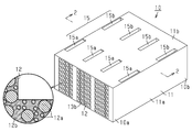
- the heat exchanger 10 of the present embodiment includes a rectangular cylindrical peripheral wall 11, a plurality of first cells 13 a extending in the axial direction of the peripheral wall 11 inside the peripheral wall 11, and a plurality of second cells. And a partition wall 12 that partitions the cell 13b.
- the rectangular cylindrical peripheral wall 11 has a pair of vertical side walls 11a opposed to each other, and a pair of horizontal side walls 11b opposed to each other, and the sectional shape orthogonal to the axial direction of the peripheral wall 11 is a horizontally long rectangle. It is done.
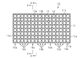
- the partition wall 12 includes a partition wall 12 parallel to the vertical side wall 11 a and a partition wall 12 parallel to the horizontal side wall 11 b in a cross section orthogonal to the axial direction of the peripheral wall 11. It constitutes a cell structure.
- the cell structure formed by the partition wall 12 is not particularly limited.
- the wall thickness of the partition wall 12 is 0.1 to 0.5 mm, and the cell density is a cross section orthogonal to the axial direction of the peripheral wall 11
- the cell structure can be 15 to 93 cells per 1 cm 2 .
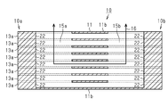
- the first cell 13 a is a cell in which the first fluid flows, and both ends thereof are sealed by the sealing portion 22.
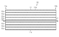
- the second cell 13 b is a cell through which the second fluid flows, and both ends thereof are open.
- the first fluid is not particularly limited, and, for example, a known heat medium can be used.
- a heat medium organic solvents, such as cooling water (Long Life Coolant: LLC) and ethylene glycol, are mentioned, for example.
- the second fluid is not particularly limited, and examples thereof include exhaust gas of an internal combustion engine.
- the heat exchanger 10 has a plurality of first cell rows 14 a in which only the first cells 13 a are arranged in parallel to the vertical side wall 11 a of the peripheral wall 11 and only the second cell 13 b in parallel to the vertical side wall 11 a. And a second cell row 14b arranged in an array.
- four second cell rows 14 b are arranged between adjacent first cell rows 14 a, and an arrangement pattern in which this arrangement is repeated is formed.
- the first cell row 14a is provided with a communicating portion 15 formed to extend in the longitudinal direction which is a direction along the longitudinal side wall 11a,
- the communication portion 15 penetrates the partition walls 12 which partition the first cells 13a adjacent to each other in the longitudinal direction, and allows the cells constituting the first cell row 14a to communicate with each other.
- the end on one side (upper side in FIG. 3) of the communicating portion 15 in the longitudinal direction opens to the peripheral wall 11 (horizontal side wall 11 b), and the end on the other side (lower side in FIG. 3) extends in the longitudinal direction It reaches the first cell 13a located on the other side.
- the heat exchanger 10 includes, as the communicating portion 15, a first communicating portion 15a provided on the side of the first end 10a, which is one end of the heat exchanger 10 in the axial direction, and the axial direction of the heat exchanger 10. It has the 2nd communicating part 15b provided in the 2nd end 10b side which is the other end.
- the heat exchanger 10 is formed with a first flow path 16 formed of a first cell 13 a, a first communication portion 15 a and a second communication portion 15 b inside the heat exchanger 10.
- the opening of the first communication portion 15a and the opening of the second communication portion 15b formed in the peripheral wall 11 of 10 function as an inlet or an outlet of the first flow passage 16, respectively.
- a second flow passage 17 configured of the second cell 13 b is formed in the heat exchanger 10, and the first end 10 a and the second end of the peripheral wall 11 are formed. 10b function as an inlet or an outlet of the second flow passage 17, respectively.
- the heat exchanger 10 configured as described above can perform heat exchange between the first fluid flowing in the first flow passage 16 and the second fluid flowing in the second flow passage 17 via the partition wall 12.
- the partition wall 12 is provided with a skeleton portion 12a of a porous structure, and a filling portion 12b made of metal which is filled in the gap of the skeleton portion 12a and covers the surface of the skeleton portion 12a.
- the skeleton portion 12a contains silicon carbide as a main component.
- main component means 50 mass% or more.
- the skeletal portion 12a may contain components other than silicon carbide.
- ceramic materials such as carbides, such as tantalum carbide and tungsten carbide, nitrides, such as silicon nitride and a boron nitride, are mentioned, for example. When it contains components other than silicon carbide, only 1 type of the said component may be contained, and 2 or more types may be contained.
- metal silicon As a metal which comprises the filling part 12b, metal silicon, aluminum, iron, and copper are mentioned, for example. Among these, metal silicon is particularly preferable. Moreover, the metal which comprises the filling part 12b may consist only of 1 type of said metals, and may consist of 2 or more types.
- the volume ratio (framework portion: filling portion) of the framework portion 12a to the filling portion 12b in the partition wall 12 is preferably, for example, 60:40 to 40:60.
- the volume of the metal constituting the filling portion 12 b is preferably larger than the pore volume, and more preferably 1.01 to 1.1 times the pore volume.
- the surface roughness of the partition wall can be increased by making it 1.01 times or more, and metal deposition can be prevented by making the surface roughness 1.1 or less. .
- the surface of the partition wall 12 is constituted by the filling portion 12 b.
- the surface roughness (arithmetic average roughness: Ra) of the partition wall 12 is 1.0 ⁇ m or more, and preferably 1.2 ⁇ m or more.
- the surface roughness of the partition wall 12 is preferably 5.0 ⁇ m or less.
- the surface roughness of the partition wall 12 can be adjusted by changing the conditions at the time of impregnating a metal into the framework part 12a of a porous structure, and forming the filling part 12b.
- the measuring method of surface roughness Ra is as follows.
- the partition wall is cut out from the heat exchanger into a plate of 10 mm ⁇ 10 mm and used as a sample.
- the surface roughness Ra of the sample is measured along the longitudinal direction of the flow channel with a measurement span of 2 mm using a surface roughness measuring device (for example, Surfcom 1400d manufactured by Tokyo Seimitsu Co., Ltd.). The same measurement is performed three times, and the average value is determined.
- the heat exchanger is manufactured by sequentially passing through a forming process, a processing process, a degreasing process, and an impregnating process described below.
- a clay-like mixture containing particles of silicon carbide, an organic binder, and a dispersion medium is prepared as a raw material used for forming a heat exchanger. At this time, if necessary, particles other than silicon carbide such as ceramic particles may be mixed.
- the average particle diameter (50% particle diameter) of particles of silicon carbide and particles other than silicon carbide is preferably, for example, 0.5 to 50 ⁇ m.
- the organic binder include polyvinyl alcohol, methyl cellulose, ethyl cellulose and carboxymethyl cellulose. Among these organic binders, methyl cellulose and carboxymethyl cellulose are particularly preferable. Moreover, only 1 type of said organic binders may be used, and 2 or more types may be used together.
- dispersion medium examples include water and organic solvents.
- organic solvent examples include ethanol is mentioned, for example.
- only one of the above dispersion media may be used, or two or more may be used in combination.
- plasticizers examples include polyoxyalkylene compounds such as polyoxyethylene alkyl ether and polyoxypropylene alkyl ether.
- the lubricant includes, for example, glycerin.
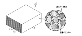
- the clay-like mixture is used to form a compact 20 shown in FIG.
- the molded body 20 includes a rectangular cylindrical peripheral wall 11 and a dividing wall 12 dividing the inside of the peripheral wall 11 into a plurality of cells 13 extending in the axial direction of the peripheral wall 11. Both ends of all the cells 13 contained in the molded body 20 are open.
- the molded body 20 can be molded, for example, by extrusion molding.
- the obtained formed body 20 is subjected to a drying process to dry the formed body 20.
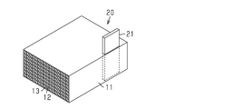
- processing step the first processing for forming the first communication portion and the second communication portion in the molded body and the second processing for sealing the both end portions of some of the cells in the molded body are performed.
- a blade having an outer shape corresponding to the first communication portion 15 a and the second communication portion 15 b is prepared as the processing tool 21.
- the blade is formed of a heat-resistant metal (for example, stainless steel), and its thickness is set to a thickness that does not exceed the width of the first cell 13a.
- the blade is heated to a temperature at which the organic binder contained in the formed body 20 is burned off. For example, when the organic binder is methyl cellulose, the blade is heated to 400 ° C. or higher.
- the clay-like one used in the forming step is applied to both end portions of the cells 13 that constitute the first cell 13a.
- the mixture is filled to form a sealing portion 22 which seals both ends of the cell 13.
- the molded body 20 is subjected to a drying process to dry the sealing portion 22.
- a processed and formed body is obtained through the processing steps including the first processing and the second processing.
- the order of the first processing and the second processing is not particularly limited, and the first processing may be performed after the second processing.
- the processed and formed body is heated to burn off the organic binder contained in the formed and formed body.
- a degreased body from which the organic binder has been removed from the processed and formed body is obtained.
- the degreased body 30 obtained by removing the organic binder from the processed and formed body through the degreasing step has a porous structure in which there are gaps between the particles of silicon carbide.
- the volume (pore volume) of the gap in the degreased body 30 is preferably 40 to 60% by volume.
- the pore volume of the degreased body 30 can be adjusted by changing the content of silicon carbide particles in the mixture used in the forming step.
- the inside of each wall constituting the degreased body is impregnated with a metal such as metal silicon.
- a metal such as metal silicon.
- the melting point of the metal or higher for example, metal silicon, Heat to 1450 ° C. or higher.
- the molten metal enters the gap between the particles constituting the degreased body by capillary action, and the gap is impregnated with the metal.
- the site of the degreased body to be in contact with the metal lump is not particularly limited, but from the viewpoint of efficiency, it is preferable to contact the metal lump on the top of the degreased body.
- metallic silicon When using metallic silicon, it is preferable to use metallic silicon whose purity is less than 98%. Metallic silicon (mass of metallic silicon) tends to have a lower melting point as its purity decreases. Therefore, by using metal silicon of low purity, the heating temperature required for the impregnation step can be suppressed low. As a result, the manufacturing cost can be suppressed.
- the purity of metal silicon is, for example, 95% or more.
- the amount of metal lumps to be brought into contact with the degreased body (the amount of metal loaded into the degreased body) is made larger than the amount corresponding to the pore volume of the degreased body 30, or Make it less than the corresponding amount.
- the preparation amount of metal is set to an amount corresponding to a volume of 1.01 to 1.1 times the pore volume of the degreased body 30.
- the preparation amount of metal is larger than the amount corresponding to the pore volume of the degreased body 30, a part of the impregnated metal overflows the pores of the degreased body 30, and a convex portion is formed on the surface. As a result, the surface roughness of the peripheral wall and the partition wall formed becomes large.
- the preparation amount of the metal is smaller than the amount corresponding to the pore volume of the degreased body 30, the uneven shape based on the pores of the degreased body 30 floats on the surface of the peripheral wall and the partition wall to be formed. As a result, the surface roughness of the peripheral wall and the partition wall formed becomes large.
- the heat treatment in the impregnation step may be performed continuously from the heat treatment in the degreasing step.
- the organic binder is removed by heating at a temperature lower than the melting point of metallic silicon to form a degreased body, and then the heating temperature is the melting point of metallic silicon
- the molten metal silicon may be impregnated into the degreased body by raising it above.
- a heat exchanger is obtained by passing through the above-mentioned impregnation process.
- special temperature control is performed in steps after the degreasing step. That is, the steps after the degreasing step are carried out at a temperature lower than the sintering temperature of silicon carbide contained in the mixture used in the forming step, and the processed formed body and the degreased body are not exposed to temperatures higher than the above sintering temperature. I have to. Therefore, in the degreasing step, heating is performed at a temperature equal to or higher than the temperature at which the organic binder can be burned off and lower than the sintering temperature. Similarly, in the impregnation step, heating is performed at a temperature equal to or higher than the melting point of the metal and lower than the sintering temperature.
- the heat exchanger includes a first cell for circulating the first fluid, a second cell for circulating the second fluid, and a partition wall for partitioning the first cell and the second cell.
- the partition wall is provided with a framework portion mainly composed of silicon carbide and a filling portion made of metal which is filled in a gap of the framework portion and which covers the surface of the framework portion.
- the surface roughness Ra of the partition wall is 1.0 ⁇ m or more.
- the contact area between the fluid and the partition wall when the first fluid and the second fluid flow is increased.
- the heat transfer efficiency from the fluid to the partition wall and the heat transfer efficiency from the partition wall to the fluid are improved, and the heat exchange efficiency of the heat exchanger is improved.
- the filling portion is metal silicon.
- the thermal conductivity of the partition wall can be increased, and the heat exchange efficiency can be improved.
- metallic silicon has a small difference in thermal expansion coefficient with silicon carbide forming a skeleton, it is possible to prevent damage due to thermal shock during use.
- the surface roughness Ra of the partition wall is 5.0 ⁇ m or less. According to the above configuration, it is possible to suppress the first fluid and the second fluid flowing along the partition wall from becoming turbulent and increasing the flow resistance due to the surface shape of the partition wall.
- a method of manufacturing a heat exchanger comprising: a first cell for circulating the first fluid; a second cell for circulating the second fluid; and a partition wall for partitioning the first cell and the second cell, silicon carbide Forming a mixture containing particles, an organic binder, and a dispersion medium to obtain a formed body, degreasing to remove the organic binder contained in the formed body to obtain a porous degreased body, and the inside of the degreased body And impregnating with metal.
- the impregnation step heating is performed above the melting point of the metal in a state in which a metal mass is in contact with the degreased body, and the metal is impregnated with an amount corresponding to a volume of 1.01 to 1.1 times the pore volume of the degreased body. Be done.
- a partition wall formed by impregnating a porous body of silicon carbide with a metal such as metal silicon tends to be a smooth surface with few irregularities because it has a dense body structure.
- a metal such as metal silicon
- the metal silicon is very high. Being present in small units, it is difficult to form asperities after vapor deposition, and it tends to become partition walls of a smooth surface.
- the partition wall is formed by impregnating the porous body of silicon carbide with a metal, the surface roughness of the partition wall can be increased.
- the metal to be impregnated into the inside of the degreased body is silicon metal.
- the metal silicon has good wettability with the silicon carbide forming the skeleton, so that the silicon carbide particles can be filled without gaps.
- the heat exchanger according to the present embodiment is manufactured under the above-described temperature control, so that the particles of silicon carbide are arranged in contact with each other to form a skeletal portion, and the gaps in the skeletal portion Is filled with metallic silicon and the shape is maintained. That is, the particles of silicon carbide do not have a joint (neck) due to sintering. Thereby, during use of the heat exchanger, it is possible to suppress the occurrence of cracks in the neck between the particles of silicon carbide, even if strain occurs inside the section wall due to the temperature difference inside. Moreover, it can suppress that a crack extends via a neck.
- the present embodiment can be implemented with the following modifications. Moreover, it is also possible to implement combining suitably the structure shown to the structure of the said embodiment, and the following modification.
- the shape of the heat exchanger (for example, the outer shape of the heat exchanger body or the cell shape) is not limited to the above embodiment, and can be changed as appropriate.
- the peripheral wall also has a skeleton portion and a filling portion as in the partition wall, and the surface roughness Ra is 1.0 ⁇ m or more.
- the material of the peripheral wall and the surface shape of the peripheral wall Is not particularly limited.
- the processing step is a step for bringing the shape of the molded body obtained by the molding step closer to the shape of the heat exchanger to be manufactured. Therefore, in the processing step, only necessary processing may be performed according to the shape of the heat exchanger to be manufactured and the shape of the formed body. In addition, in the processing step, processing other than the first processing and the second processing may be performed. However, processing including removal of a part of the molded body is preferably performed by an operation of bringing a processing tool heated to a temperature at which the organic binder is burned out into contact with the molded body.
- steps other than the forming step, the processing step, the degreasing step, and the impregnation step may be further performed.
- surface processing such as polishing may be performed.
- Example 1 First, a mixture of the following composition was prepared.
- a molded body having the same shape as that of the above was molded to have a length of 50 mm, a width of 100 mm, a length of 100 mm, a peripheral wall thickness of 0.3 mm, a partition wall thickness of 0.25 mm, and a cell width of 1.2 mm.
- a plate-like jig heated to 400 ° C. was inserted into the peripheral wall of the molded body to form a first communication portion and a second communication portion.
- predetermined cells were sealed to prepare a processed and formed article having a first cell and a second cell.
- the processed and formed body was heated at 450 ° C. for 5 hours to obtain a degreased body from which the organic binder was removed.
- the plate material of metal silicon 153 g the preparation amount: an amount corresponding to 1.05 times the volume of the pore volume of the degreased body
- heating is conducted at 1550 ° C. for 7 hours under vacuum.
- metal silicon was impregnated to obtain the heat exchanger of Example 1.
- Example 2 in the same manner as Example 1 except that the amount (feed amount) of the metal silicon plate was 147.2 g (an amount corresponding to a volume of 1.01 times the pore volume of the degreased body). I got a heat exchanger.
- Example 3 in the same manner as Example 1 except that the amount (feed amount) of the metal silicon plate was 160.3 g (an amount corresponding to a volume of 1.1 times the pore volume of the degreased body). I got a heat exchanger.
- Comparative example A comparative example was prepared in the same manner as in Example 1, except that the amount (feed amount) of the metal silicon plate was 145.7 g (an amount corresponding to a volume 1.0 times the pore volume of the degreased body). I got a heat exchanger.
- the surface roughness of the partition wall in the comparative example was set to 0.5 ⁇ m in the amount corresponding to 1 time of the pore volume of the degreased body.
- the surface roughness of the partition wall in Examples 1 to 3 in which the preparation amount of metal silicon in the impregnation step was larger than the pore volume of the degreased body was 1.0 to 4.5 ⁇ m. From this result, it is understood that the surface roughness of the partition wall can be increased by increasing the amount of metal silicon charged relative to the pore volume of the degreased body.
Landscapes
- Engineering & Computer Science (AREA)
- Physics & Mathematics (AREA)
- Thermal Sciences (AREA)
- Mechanical Engineering (AREA)
- General Engineering & Computer Science (AREA)
- Ceramic Engineering (AREA)
- Heat-Exchange Devices With Radiators And Conduit Assemblies (AREA)
- Ceramic Products (AREA)
Abstract
熱交換器10は、第1流体を流通させる第1セルと、第2流体を流通させる第2セルと、第1セル及び第2セルを区画する区画壁12とを備えている。区画壁12は、炭化ケイ素を主成分とする骨格部分12aと、骨格部分12aの隙間に充填されるとともに骨格部分12aの表面を覆う金属からなる充填部分12bとを備えている。区画壁12の表面粗さRaは1.0μm以上である。
Description
本発明は、熱交換器、及び熱交換器の製造方法に関する。
従来、車両等に搭載される熱交換器として、区画壁により区画された複数の第1流路及び複数の第2流路を備え、第1流路を流通する第1流体と第2流路を流通する第2流体との間で、区画壁を介して熱交換を行う熱交換器が知られている。こうした熱交換器の区画壁は、熱伝導率の高い材料により構成されていることが好ましい。例えば、特許文献1には、炭化ケイ素の多孔質体に金属ケイ素を含浸させてなる緻密体構造の区画壁とすることにより、区画壁の熱伝導率を高める技術が開示されている。なお、上記緻密体構造の区画壁は、金属ケイ素雰囲気下に炭化ケイ素の多孔質体を載置して、金属ケイ素を蒸着させることにより形成されている。
炭化ケイ素の多孔質体に金属ケイ素等の金属を含浸させてなる区画壁は、緻密体構造であることから、凹凸の少ない滑らかな表面になりやすい傾向がある。特に、特許文献1に開示されるように、金属ケイ素雰囲気下に炭化ケイ素の多孔質体を載置して、金属ケイ素を蒸着させることによって区画壁を形成した場合には、金属ケイ素が非常に小さい単位で存在するために、蒸着後に凹凸が形成され難く、滑らかな表面の区画壁になりやすい。そのため、区画壁と流路を流れる流体との接触面積が小さくなり、熱交換効率が低いという問題があった。この発明の目的は、炭化ケイ素の多孔質体に金属ケイ素等の金属を含浸させてなる区画壁を備える熱交換器に関して、その熱交換効率を向上させることにある。
上記課題を解決するための本発明の熱交換器は、第1流体を流通させる第1セルと、第2流体を流通させる第2セルと、上記第1セル及び上記第2セルを区画する区画壁とを備え、上記第1流体と上記第2流体との間で熱交換が行われる熱交換器であって、上記区画壁は、炭化ケイ素を主成分とする骨格部分と、上記骨格部分の隙間に充填されるとともに上記骨格部分の表面を覆う金属からなる充填部分とを備え、上記区画壁の表面粗さRaが1.0μm以上である。
区画壁の表面粗さRaを1.0μm以上にすることで、流体と区画壁との接触面積を増やすことができるため、熱交換効率を向上させることができる。
本発明の熱交換器について、上記金属は、金属ケイ素であることが好ましい。金属ケイ素にすることで、区画壁の熱伝導率を高くすることができ、熱交換効率を向上させることができる。また、金属ケイ素は骨格部分をなす炭化ケイ素との熱膨張係数差が小さいため、使用中の熱衝撃による破損を防ぐことができる。
本発明の熱交換器について、上記金属は、金属ケイ素であることが好ましい。金属ケイ素にすることで、区画壁の熱伝導率を高くすることができ、熱交換効率を向上させることができる。また、金属ケイ素は骨格部分をなす炭化ケイ素との熱膨張係数差が小さいため、使用中の熱衝撃による破損を防ぐことができる。
本発明の熱交換器について、上記区画壁の表面粗さは、5.0μm以下であることが好ましい。この構成によれば、流体の流通抵抗を下げることができる。
上記課題を解決するための本発明の熱交換器の製造方法は、第1流体を流通させる第1セルと、第2流体を流通させる第2セルと、上記第1セル及び上記第2セルを区画する区画壁とを備え、上記第1流体と上記第2流体との間で熱交換が行われる熱交換器の製造方法であって、炭化ケイ素粒子、有機バインダー、及び分散媒を含有する混合物を成形して成形体を得る成形工程と、上記成形体に含まれる上記有機バインダーを除去して多孔質の脱脂体を得る脱脂工程と、上記脱脂体の内部に金属を含浸させる含浸工程とを有し、上記含浸工程では、上記脱脂体に金属の塊を接触させた状態で当該金属の融点以上に加熱して、上記脱脂体の気孔容積の1.01~1.1倍の体積に相当する量の上記金属が含浸される。
上記課題を解決するための本発明の熱交換器の製造方法は、第1流体を流通させる第1セルと、第2流体を流通させる第2セルと、上記第1セル及び上記第2セルを区画する区画壁とを備え、上記第1流体と上記第2流体との間で熱交換が行われる熱交換器の製造方法であって、炭化ケイ素粒子、有機バインダー、及び分散媒を含有する混合物を成形して成形体を得る成形工程と、上記成形体に含まれる上記有機バインダーを除去して多孔質の脱脂体を得る脱脂工程と、上記脱脂体の内部に金属を含浸させる含浸工程とを有し、上記含浸工程では、上記脱脂体に金属の塊を接触させた状態で当該金属の融点以上に加熱して、上記脱脂体の気孔容積の1.01~1.1倍の体積に相当する量の上記金属が含浸される。
炭化ケイ素の多孔質体に金属を含浸させる際の条件を調整すること、具体的には、多孔質の脱脂体に金属の塊を接触させた状態で当該金属の融点以上に加熱して金属を含浸させること、及び含浸させる金属の量を所定量とすることにより、区画壁の表面粗さを大きくすることができる。その結果、流体から区画壁への熱伝導効率、及び区画壁から流体への熱伝導効率が向上し、熱交換器の熱交換効率が向上する。
本発明の熱交換器の製造方法について、上記金属は、金属ケイ素であることが好ましい。金属ケイ素は骨格部分をなす炭化ケイ素との濡れ性がよいため、炭化ケイ素粒子間を隙間なく埋めることができる。
本発明によれば、炭化ケイ素の多孔質体に金属を含浸させてなる区画壁を備える熱交換器の熱交換効率を向上させることができる。
以下、熱交換器の一実施形態を説明する。
図1、2に示すように、本実施形態の熱交換器10は、矩形筒状の周壁11と、周壁11の内部を周壁11の軸方向に延びる複数の第1セル13a及び複数の第2セル13bに区画する区画壁12とを備えている。矩形筒状の周壁11は、互いに対向する一対の縦側壁11aと、互いに対向する一対の横側壁11bとを有し、周壁11の軸方向に直交する断面形状が横長の長方形をなすように構成されている。
図1、2に示すように、本実施形態の熱交換器10は、矩形筒状の周壁11と、周壁11の内部を周壁11の軸方向に延びる複数の第1セル13a及び複数の第2セル13bに区画する区画壁12とを備えている。矩形筒状の周壁11は、互いに対向する一対の縦側壁11aと、互いに対向する一対の横側壁11bとを有し、周壁11の軸方向に直交する断面形状が横長の長方形をなすように構成されている。
図2に示すように、区画壁12は、周壁11の軸方向に直交する断面において、縦側壁11aに平行な区画壁12と、横側壁11bに平行な区画壁12とを含み、格子状のセル構造を構成している。区画壁12が構成するセル構造は特に限定されるものではないが、例えば、区画壁12の壁厚が0.1~0.5mmであり、セル密度が、周壁11の軸方向に直交する断面1cm2あたり15~93セルであるセル構造とすることができる。
図3に示すように、第1セル13aは、第1流体を流通させるセルであり、その両端部が共に封止部22によって封止されている。図4に示すように、第2セル13bは、第2流体を流通させるセルであり、その両端部が共に開放されている。
第1流体としては特に限定されず、例えば、公知の熱媒体を用いることができる。公知の熱媒体としては、例えば、冷却水(Long Life Coolant:LLC)や、エチレングリコール等の有機溶剤が挙げられる。第2流体としては特に限定されず、例えば、内燃機関の排気ガスが挙げられる。
図2に示すように、周壁11の軸方向に直交する断面において、第1セル13aの断面形状と第2セル13bの断面形状は、全て同じである。
図2に示すように、熱交換器10は、周壁11の縦側壁11aに平行に第1セル13aのみが配列した複数の第1セル列14aと、縦側壁11aに平行に第2セル13bのみが配列した第2セル列14bとを備える。本実施形態においては、隣り合う第1セル列14a同士の間に、4列の第2セル列14bが配置され、この配置が繰り返された配置パターンが形成されている。
図2に示すように、熱交換器10は、周壁11の縦側壁11aに平行に第1セル13aのみが配列した複数の第1セル列14aと、縦側壁11aに平行に第2セル13bのみが配列した第2セル列14bとを備える。本実施形態においては、隣り合う第1セル列14a同士の間に、4列の第2セル列14bが配置され、この配置が繰り返された配置パターンが形成されている。
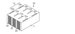
図1、3に示すように、熱交換器10において、第1セル列14aには、縦側壁11aに沿った方向である縦方向に延びるように形成された連通部15が設けられており、連通部15は、縦方向に隣接する第1セル13a同士を区画する区画壁12を貫通して、第1セル列14aを構成するセル同士を相互に連通させる。連通部15における縦方向の一方側(図3の上側)の端部は、周壁11(横側壁11b)に開口するとともに、同他方側(図3の下側)の端部は、縦方向において最も他方側に位置する第1セル13aにまで達している。すなわち、連通部15はいずれも周壁11の同一面に開口し、各連通部15は当該連通部15の開口から最も離れて位置する第1セル13aにまで延びている。熱交換器10は、連通部15として、熱交換器10の軸方向の一方の端部である第1端部10a側に設けられた第1連通部15aと、熱交換器10の軸方向の他方の端部である第2端部10b側に設けられた第2連通部15bとを有している。
図3に示すように、熱交換器10の内部には、第1セル13a、第1連通部15a及び第2連通部15bにより構成される第1流路16が形成されており、熱交換器10の周壁11に形成された第1連通部15aの開口及び第2連通部15bの開口がそれぞれ第1流路16の流入口又は流出口として機能する。また、図4に示すように、熱交換器10の内部には、第2セル13bにより構成される第2流路17が形成されており、周壁11の第1端部10a及び第2端部10bがそれぞれ第2流路17の流入口又は流出口として機能する。上記構成の熱交換器10は、第1流路16を流れる第1流体と、第2流路17を流れる第2流体との間で、区画壁12を介して熱交換を行うことができる。
次に、熱交換器10の周壁11及び区画壁12を構成する材料、並びに周壁11及び区画壁12の表面形状について説明する。なお、本実施形態の周壁11及び区画壁12は、構成する材料及び表面形状が同じであることから、以下では、区画壁12について具体的に説明し、周壁11についての説明を省略する。
図1に示すように、区画壁12は、多孔質構造の骨格部分12aと、骨格部分12aの隙間に充填されるとともに骨格部分12aの表面を覆う金属からなる充填部分12bとを備えている。骨格部分12aは、炭化ケイ素を主成分として含有する。ここで、「主成分」とは、50質量%以上を意味するものとする。骨格部分12aは、炭化ケイ素以外の成分を含有してもよい。炭化ケイ素以外の成分としては、例えば、炭化タンタル、炭化タングステン等の炭化物、窒化ケイ素、窒化ホウ素等の窒化物等のセラミック材料が挙げられる。炭化ケイ素以外の成分を含有する場合、当該成分を1種のみ含有していてもよいし、2種以上含有していてもよい。
充填部分12bを構成する金属としては、例えば、金属ケイ素、アルミニウム、鉄、銅が挙げられる。これらのなかでも、金属ケイ素が特に好ましい。また、充填部分12bを構成する金属は、上記金属のうちの1種のみからなるものであってもよいし、2種以上からなるものであってもよい。
区画壁12における骨格部分12aと充填部分12bとの体積比(骨格部分:充填部分)は、例えば、60:40~40:60であることが好ましい。充填部分12bを構成する金属の体積は、上記気孔容積よりも多いことが好ましく、上記気孔容積の1.01~1.1倍であることがより好ましい。1.01倍以上にすることで、区画壁の表面粗さを大きくすることができ、1.1倍以下にすることで、区画壁および周壁の表面に金属が堆積することを防ぐことができる。
区画壁12の表面は、充填部分12bにより構成されている。そして、区画壁12の表面粗さ(算術平均粗さ:Ra)は、1.0μm以上であり、1.2μm以上であることが好ましい。また、区画壁12の表面粗さは、5.0μm以下であることが好ましい。なお、区画壁12の表面粗さは、多孔質構造の骨格部分12aに金属を含浸させて充填部分12bを形成する際の条件を変更することにより調整することができる。
なお、表面粗さRaの測定方法は以下の通りである。
熱交換器から区画壁を10mm×10mmの板状に切り出し、サンプルとする。表面粗さ測定器(例えば、東京精密製のSurfcom1400d)を用いて、測定スパン2mmで流路の長手方向に沿ってサンプルの表面粗さRaを測定する。同様の測定を3回行い、その平均値を求める。
熱交換器から区画壁を10mm×10mmの板状に切り出し、サンプルとする。表面粗さ測定器(例えば、東京精密製のSurfcom1400d)を用いて、測定スパン2mmで流路の長手方向に沿ってサンプルの表面粗さRaを測定する。同様の測定を3回行い、その平均値を求める。
次に、図5~10に基づいて、本実施形態の熱交換器の一製造方法について説明する。熱交換器は、以下に記載する成形工程、加工工程、脱脂工程、含浸工程を順に経ることにより製造される。
(成形工程)
熱交換器の成形に用いる原料として、炭化ケイ素の粒子と、有機バインダーと、分散媒とを含有する粘土状の混合物を調製する。この際、必要に応じて、セラミック粒子等の炭化ケイ素以外の粒子を混合してもよい。
熱交換器の成形に用いる原料として、炭化ケイ素の粒子と、有機バインダーと、分散媒とを含有する粘土状の混合物を調製する。この際、必要に応じて、セラミック粒子等の炭化ケイ素以外の粒子を混合してもよい。
炭化ケイ素の粒子、及び炭化ケイ素以外の粒子の平均粒子径(50%粒子径)は、例えば、0.5~50μmであることが好ましい。
有機バインダーとしては、例えば、ポリビニルアルコール、メチルセルロース、エチルセルロース、カルボキシメチルセルロースが挙げられる。これらの有機バインダーの中でも、メチルセルロース、カルボキシメチルセルロースが特に好ましい。また、上記の有機バインダーのうちの一種のみを用いてもよいし、二種以上を併用してもよい。
有機バインダーとしては、例えば、ポリビニルアルコール、メチルセルロース、エチルセルロース、カルボキシメチルセルロースが挙げられる。これらの有機バインダーの中でも、メチルセルロース、カルボキシメチルセルロースが特に好ましい。また、上記の有機バインダーのうちの一種のみを用いてもよいし、二種以上を併用してもよい。
分散媒としては、例えば、水、有機溶剤が挙げられる。有機溶剤としては、例えば、エタノールが挙げられる。また、上記の分散媒のうちの一種のみを用いてもよいし、二種以上を併用してもよい。
また、混合物中にその他の成分を更に含有させてもよい。その他の成分としては、例えば、可塑剤、潤滑剤が挙げられる。可塑剤としては、例えば、ポリオキシエチレンアルキルエーテル、ポリオキシプロピレンアルキルエーテル等のポリオキシアルキレン系化合物が挙げられる。潤滑剤としては、例えば、グリセリンが挙げられる。
この粘土状の混合物を用いて、図5に示す成形体20を成形する。成形体20は、矩形筒状の周壁11と、周壁11の内部を周壁11の軸方向に延びる複数のセル13に区画する区画壁12とを備える。この成形体20に含まれる全てのセル13について、その両端が開放された状態となっている。成形体20は、例えば、押し出し成形により成形することができる。得られた成形体20に対して、成形体20を乾燥させる乾燥処理を行う。
(加工工程)
加工工程では、成形体に第1連通部及び第2連通部を形成する第1加工と、成形体における一部のセルの両端部を封止する第2加工とを行う。
加工工程では、成形体に第1連通部及び第2連通部を形成する第1加工と、成形体における一部のセルの両端部を封止する第2加工とを行う。
図6に示すように、第1加工では、例えば、加熱された加工具21を成形体に接触させる方法を用いて、成形体20における周壁11及び区画壁12の一部を除去して、第1連通部15a及び第2連通部15bを形成する。
具体的には、図6に示すように、加工具21として、第1連通部15a及び第2連通部15bに対応する外形状を有するブレードを用意する。このブレードは、耐熱性の金属(例えば、ステンレス鋼)により形成され、その厚さは、第1セル13aの幅を超えない厚さに設定されている。次に、成形体20に含まれる有機バインダーが焼失する温度となるようにブレードを加熱する。例えば、有機バインダーがメチルセルロースである場合には、ブレードを400℃以上に加熱する。
図7に示すように、加熱されたブレードを周方向外方から成形体20に差し込んだ後、これを引き抜くことによって、第1連通部15a及び第2連通部15bを形成する。このとき、加熱されたブレードと成形体20とが接触すると、その接触部分において成形体20に含まれる有機バインダーが燃焼して焼失する。そのため、成形体20に対するブレードの挿入抵抗は非常に小さく、ブレードの挿入時に、挿入された部分の周辺部分に変形や破壊が生じ難い。また、有機バインダーが焼失することによって、発生する加工屑の量が減少する。
図8に示すように、第2加工では、成形体20に形成される複数のセル13のうち、第1セル13aを構成するセル13の両端部に対して、成形工程において用いた粘土状の混合物を充填して、当該セル13の両端部を封止する封止部22を形成する。その後、成形体20に対して、封止部22を乾燥させる乾燥処理を行う。
上記の第1加工及び第2加工を含む加工工程を経ることにより、加工成形体が得られる。第1加工と第2加工の順序は特に限定されず、第2加工を行った後、第1加工を行ってもよい。
(脱脂工程)
脱脂工程では、加工成形体を加熱することによって、加工成形体に含まれる有機バインダーを焼失させる。これにより、加工成形体から有機バインダーが除去された脱脂体が得られる。図9に示すように、脱脂工程を経ることで加工成形体から有機バインダーを除去して得られる脱脂体30は、炭化ケイ素の粒子間に隙間のある多孔質構造を有する。ここで、脱脂体30における隙間の容積(気孔容積)は、40~60体積%であることが好ましい。脱脂体30の気孔容積は、成形工程において用いられる混合物中の炭化ケイ素の粒子の含有率を変更することにより調整できる。
脱脂工程では、加工成形体を加熱することによって、加工成形体に含まれる有機バインダーを焼失させる。これにより、加工成形体から有機バインダーが除去された脱脂体が得られる。図9に示すように、脱脂工程を経ることで加工成形体から有機バインダーを除去して得られる脱脂体30は、炭化ケイ素の粒子間に隙間のある多孔質構造を有する。ここで、脱脂体30における隙間の容積(気孔容積)は、40~60体積%であることが好ましい。脱脂体30の気孔容積は、成形工程において用いられる混合物中の炭化ケイ素の粒子の含有率を変更することにより調整できる。
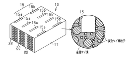
(含浸工程)
含浸工程では、脱脂体を構成する各壁の内部に金属ケイ素等の金属を含浸させる。含浸工程においては、脱脂体に対して金属の塊を接触させた状態で、アルゴンや窒素等の不活性ガス雰囲気下、又は真空下にて、金属の融点以上(例えば、金属ケイ素である場合、1450℃以上)に加熱する。これにより、図10に示すように、溶融した金属が毛細管現象によって、脱脂体を構成する粒子間の隙間へ入り込み、同隙間に金属が含浸される。脱脂体における金属の塊を接触させる部位は特に限定されるものではないが、効率化の観点においては、脱脂体の上部に金属の塊を接触させることが好ましい。
含浸工程では、脱脂体を構成する各壁の内部に金属ケイ素等の金属を含浸させる。含浸工程においては、脱脂体に対して金属の塊を接触させた状態で、アルゴンや窒素等の不活性ガス雰囲気下、又は真空下にて、金属の融点以上(例えば、金属ケイ素である場合、1450℃以上)に加熱する。これにより、図10に示すように、溶融した金属が毛細管現象によって、脱脂体を構成する粒子間の隙間へ入り込み、同隙間に金属が含浸される。脱脂体における金属の塊を接触させる部位は特に限定されるものではないが、効率化の観点においては、脱脂体の上部に金属の塊を接触させることが好ましい。
金属ケイ素を用いる場合には、その純度が98%未満の金属ケイ素を用いることが好ましい。金属ケイ素(金属ケイ素の塊)は、その純度が低くなるにしたがって融点が低くなる傾向がある。そのため、低純度の金属ケイ素を用いることにより、含浸工程に要する加熱温度を低く抑えることができる。その結果、製造コストを抑制することができる。なお、金属ケイ素の純度は、例えば、95%以上である。
ここで、脱脂体に接触させる金属の塊の量(脱脂体に充填される金属の仕込み量)を、脱脂体30の気孔容積に相当する量よりも多くする、又は脱脂体30の気孔容積に相当する量よりも少なくする。具体的には、金属の仕込み量を、脱脂体30の気孔容積の1.01~1.1倍の体積に相当する量とする。
金属の仕込み量を、脱脂体30の気孔容積に相当する量よりも多くした場合には、含浸された金属の一部が脱脂体30の気孔から溢れて表面に凸部を形成する。その結果、形成される周壁及び区画壁の表面粗さが大きくなる。また、金属の仕込み量を、脱脂体30の気孔容積に相当する量よりも少なくした場合には、形成される周壁及び区画壁の表面に脱脂体30の気孔に基づく凹凸形状が浮き出る。その結果、形成される周壁及び区画壁の表面粗さが大きくなる。
なお、含浸工程の加熱処理は、脱脂工程の加熱処理から連続して行ってもよい。例えば、加工成形体に対して金属ケイ素の塊を接触させた状態で、金属ケイ素の融点未満の温度で加熱することにより有機バインダーを除去して脱脂体とした後、加熱温度を金属ケイ素の融点以上に上昇させ、溶融した金属ケイ素を脱脂体に含浸させてもよい。
上記の含浸工程を経ることにより、熱交換器が得られる。
ここで、本実施形態においては、脱脂工程以降の工程において特別な温度管理を行っている。すなわち、脱脂工程以降の工程は、成形工程に用いた混合物に含まれる炭化ケイ素の焼結温度未満の温度下で実施され、加工成形体及び脱脂体を上記焼結温度以上の温度に曝さないようにしている。したがって、脱脂工程においては、有機バインダーが焼失可能な温度以上、かつ上記焼結温度未満の温度で加熱を行う。同様に、含浸工程においては、金属の融点以上、かつ上記焼結温度未満の温度で加熱を行う。
ここで、本実施形態においては、脱脂工程以降の工程において特別な温度管理を行っている。すなわち、脱脂工程以降の工程は、成形工程に用いた混合物に含まれる炭化ケイ素の焼結温度未満の温度下で実施され、加工成形体及び脱脂体を上記焼結温度以上の温度に曝さないようにしている。したがって、脱脂工程においては、有機バインダーが焼失可能な温度以上、かつ上記焼結温度未満の温度で加熱を行う。同様に、含浸工程においては、金属の融点以上、かつ上記焼結温度未満の温度で加熱を行う。
次に、本実施形態の作用及び効果について記載する。
(1)熱交換器は、第1流体を流通させる第1セルと、第2流体を流通させる第2セルと、第1セル及び第2セルを区画する区画壁とを備えている。区画壁は、炭化ケイ素を主成分とする骨格部分と、骨格部の隙間に充填されるとともに骨格部の表面を覆う金属からなる充填部分とを備えている。区画壁の表面粗さRaが1.0μm以上である。
(1)熱交換器は、第1流体を流通させる第1セルと、第2流体を流通させる第2セルと、第1セル及び第2セルを区画する区画壁とを備えている。区画壁は、炭化ケイ素を主成分とする骨格部分と、骨格部の隙間に充填されるとともに骨格部の表面を覆う金属からなる充填部分とを備えている。区画壁の表面粗さRaが1.0μm以上である。
上記構成によれば、第1流体及び第2流体が流通する際における流体と区画壁との接触面積が大きくなる。その結果、流体から区画壁への熱伝導効率、及び区画壁から流体への熱伝導効率が向上し、熱交換器の熱交換効率が向上する。
(2)充填部分は、金属ケイ素である。
金属ケイ素からなる充填部分とすることで、区画壁の熱伝導率を高くすることができ、熱交換効率を向上させることができる。また、金属ケイ素は骨格部分をなす炭化ケイ素との熱膨張係数差が小さいため、使用中の熱衝撃による破損を防ぐことができる。
金属ケイ素からなる充填部分とすることで、区画壁の熱伝導率を高くすることができ、熱交換効率を向上させることができる。また、金属ケイ素は骨格部分をなす炭化ケイ素との熱膨張係数差が小さいため、使用中の熱衝撃による破損を防ぐことができる。
(3)区画壁の表面粗さRaが5.0μm以下である。
上記構成によれば、区画壁の表面形状に起因して、区画壁に沿って流れる第1流体及び第2流体が乱流となって流通抵抗が大きくなることを抑制できる。
上記構成によれば、区画壁の表面形状に起因して、区画壁に沿って流れる第1流体及び第2流体が乱流となって流通抵抗が大きくなることを抑制できる。
(4)第1流体を流通させる第1セルと、第2流体を流通させる第2セルと、第1セル及び第2セルを区画する区画壁とを備える熱交換器の製造方法は、炭化ケイ素粒子、有機バインダー、及び分散媒を含有する混合物を成形して成形体を得る成形工程と、成形体に含まれる有機バインダーを除去して多孔質の脱脂体を得る脱脂工程と、脱脂体の内部に金属を含浸させる含浸工程とを有する。含浸工程では、脱脂体に金属の塊を接触させた状態で当該金属の融点以上に加熱して、脱脂体の気孔容積の1.01~1.1倍の体積に相当する量の金属が含浸される。
通常、炭化ケイ素の多孔質体に金属ケイ素等の金属を含浸させてなる区画壁は、緻密体構造であることから、凹凸の少ない滑らかな表面になりやすい傾向がある。特に、特許文献1に開示されるように、金属ケイ素雰囲気下に炭化ケイ素の多孔質体を載置して、金属ケイ素を蒸着させることによって区画壁を形成した場合には、金属ケイ素が非常に小さい単位で存在するために、蒸着後に凹凸が形成され難く、滑らかな表面の区画壁になりやすい。これに対して、上記構成によれば、炭化ケイ素の多孔質体に金属を含浸させることにより区画壁を形成した場合にも、区画壁の表面粗さを大きくすることができる。
(5)脱脂体の内部に含浸される金属は、金属ケイ素である。
金属ケイ素は骨格部分をなす炭化ケイ素との濡れ性がよいため、炭化ケイ素粒子間を隙間なく埋めることができる。
金属ケイ素は骨格部分をなす炭化ケイ素との濡れ性がよいため、炭化ケイ素粒子間を隙間なく埋めることができる。
(6)含浸工程において、脱脂体の上に金属の塊を載せた状態で加熱を行っている。
上記構成によれば、溶融した金属が脱脂体の各壁をつたって下方へと流れる作用を利用することで、効率的に金属を含浸させることができる。
上記構成によれば、溶融した金属が脱脂体の各壁をつたって下方へと流れる作用を利用することで、効率的に金属を含浸させることができる。
(7)本実施形態の熱交換器は、上記のような温度管理下で製造されることにより、炭化ケイ素の粒子同士が接触した状態で配置されて骨格部分が形成され、この骨格部分の隙間に金属ケイ素が充填されて形状が保持されたものとなる。すなわち、炭化ケイ素の粒子同士は、焼結による結合部(ネック)を有していない状態となっている。これにより、熱交換器の使用中に、内部の温度差に起因して区画壁の内部にひずみが生じても、炭化ケイ素の粒子間のネックに亀裂が生じることを抑制することができる。また、ネックを介して亀裂が伸展することを抑制することができる。
本実施形態は、次のように変更して実施することも可能である。また、上記実施形態の構成や以下の変更例に示す構成を適宜組み合わせて実施することも可能である。
・熱交換器の形状(例えば、熱交換器体の外形やセル形状)は、上記実施形態に限定されるものではなく、適宜、変更することができる。
・熱交換器の形状(例えば、熱交換器体の外形やセル形状)は、上記実施形態に限定されるものではなく、適宜、変更することができる。
・上記実施形態では、区画壁と同様に周壁についても、骨格部分及び充填部分を備え、表面粗さRaが1.0μm以上となるように構成していたが、周壁の材料及び周壁の表面形状は特に限定されるものではない。
・熱交換器の製造方法に関して、加工工程の一部又は全部を省略してもよい。加工工程は、成形工程により得られる成形体の形状を、製造される熱交換器の形状に近づけるための工程である。そのため、加工工程においては、製造される熱交換器の形状、及び成形体の形状に応じて、必要な加工のみを行えばよい。また、加工工程において、上記第1加工及び第2加工以外の加工を行ってもよい。ただし、成形体の一部を除去することを含む加工については、有機バインダーが焼失する温度に加熱された加工具を成形体に接触させる操作によって行うことが好ましい。
・熱交換器の製造方法に関して、成形工程、加工工程、脱脂工程、含浸工程以外の工程を更に行ってもよい。例えば、含浸工程後に、研磨等の表面加工を行ってもよい。ただし、脱脂工程以降に行う処理については、含浸工程と同様に所定温度以下にて行うことが好ましい。
以下、上記実施形態をさらに具体化した実施例について説明する。
(実施例1)
まず、下記組成の混合物を調製した。
(実施例1)
まず、下記組成の混合物を調製した。
平均粒子径15μmの炭化ケイ素の粒子(大粒子):52.5質量部
平均粒子径0.5μmの炭化ケイ素の粒子(小粒子):23.6質量部
メチルセルロース(有機バインダー):5.4質量部
グリセリン(潤滑剤):1.1質量部
ポリオキシアルキレン系化合物(可塑剤):3.2質量部
水(分散媒):11.5質量部
この混合物を用いて、図5に示したものと同様の形状を有し、縦50mm、横100mm、長さ100mm、周壁の厚さ0.3mm、区画壁の厚さ0.25mm、セル幅1.2mmの成形体を成形した。
平均粒子径0.5μmの炭化ケイ素の粒子(小粒子):23.6質量部
メチルセルロース(有機バインダー):5.4質量部
グリセリン(潤滑剤):1.1質量部
ポリオキシアルキレン系化合物(可塑剤):3.2質量部
水(分散媒):11.5質量部
この混合物を用いて、図5に示したものと同様の形状を有し、縦50mm、横100mm、長さ100mm、周壁の厚さ0.3mm、区画壁の厚さ0.25mm、セル幅1.2mmの成形体を成形した。
次に、成形体の周壁に400℃に加熱した板状の治具を挿入して、第1連通部及び第2連通部を形成した。また、上記混合物と同じ組成を有する粘土状の混合物を用いて、所定のセルを封止して第1セル及び第2セルを有する加工成形体を作成した。次に、加工成形体を450℃で5時間加熱することにより、有機バインダーが除去された脱脂体を得た。その後、脱脂体の上に金属ケイ素の板材153g(仕込み量:脱脂体の気孔容積の1.05倍の体積に相当する量)を載置した状態で、真空下、1550℃で7時間、加熱することにより、金属ケイ素を含浸させて、実施例1の熱交換器を得た。
(実施例2)
金属ケイ素の板材の量(仕込み量)を、147.2g(脱脂体の気孔容積の1.01倍の体積に相当する量)とした点を除いて、実施例1と同様にして実施例2の熱交換器を得た。
金属ケイ素の板材の量(仕込み量)を、147.2g(脱脂体の気孔容積の1.01倍の体積に相当する量)とした点を除いて、実施例1と同様にして実施例2の熱交換器を得た。
(実施例3)
金属ケイ素の板材の量(仕込み量)を、160.3g(脱脂体の気孔容積の1.1倍の体積に相当する量)とした点を除いて、実施例1と同様にして実施例3の熱交換器を得た。
金属ケイ素の板材の量(仕込み量)を、160.3g(脱脂体の気孔容積の1.1倍の体積に相当する量)とした点を除いて、実施例1と同様にして実施例3の熱交換器を得た。
(比較例)
金属ケイ素の板材の量(仕込み量)を、145.7g(脱脂体の気孔容積の1.0倍の体積に相当する量)とした点を除いて、実施例1と同様にして比較例の熱交換器を得た。
金属ケイ素の板材の量(仕込み量)を、145.7g(脱脂体の気孔容積の1.0倍の体積に相当する量)とした点を除いて、実施例1と同様にして比較例の熱交換器を得た。
(表面粗さの測定)
測定用サンプルとして、各実施例及び比較例の熱交換器から横10mm×長さ10mmの区画壁を切り出した。表面粗さ測定器を用いて測定用サンプルの表面粗さ(算術平均粗さ:Ra)を測定した。表面粗さ測定器としては、東京精密社製Surfcom1400dを使用した。その結果を表1に示す。
測定用サンプルとして、各実施例及び比較例の熱交換器から横10mm×長さ10mmの区画壁を切り出した。表面粗さ測定器を用いて測定用サンプルの表面粗さ(算術平均粗さ:Ra)を測定した。表面粗さ測定器としては、東京精密社製Surfcom1400dを使用した。その結果を表1に示す。
(排熱回収量の測定)
各実施例及び比較例の熱交換器に対して、流入口から第1セルに40℃の冷却水を10L/minの流量で導入するとともに、第2セルに400℃の高温ガスを10g/secの流量で導入し、冷却水の流入時と排出時の温度差を測定して、それぞれの熱交換器の排熱回収量を算出した。その結果を表1に示す。
各実施例及び比較例の熱交換器に対して、流入口から第1セルに40℃の冷却水を10L/minの流量で導入するとともに、第2セルに400℃の高温ガスを10g/secの流量で導入し、冷却水の流入時と排出時の温度差を測定して、それぞれの熱交換器の排熱回収量を算出した。その結果を表1に示す。

また、実施例1~3の結果から、区画壁の表面粗さRaを大きくすることで、流体と区画壁との接触面積を大きくすることができ、排熱回収量が大きくなることが確認できた。したがって、区画壁の表面粗さRaを大きくすることで、熱交換効率を向上させることができることが分かる。
10…熱交換器、11…周壁、12…区画壁、12a…骨格部分、12b…充填部分、13a…第1セル、13b…第2セル、20…成形体、30…脱脂体。
Claims (5)
- 第1流体を流通させる第1セルと、第2流体を流通させる第2セルと、前記第1セル及び前記第2セルを区画する区画壁とを備え、前記第1流体と前記第2流体との間で熱交換が行われる熱交換器であって、
前記区画壁は、炭化ケイ素を主成分とする骨格部分と、前記骨格部分の隙間に充填されるとともに前記骨格部分の表面を覆う金属からなる充填部分とを備え、
前記区画壁の表面粗さRaが1.0μm以上であることを特徴とする熱交換器。 - 前記金属は、金属ケイ素である請求項1に記載の熱交換器。
- 前記区画壁の表面粗さRaが5.0μm以下である請求項1又は請求項2に記載の熱交換器。
- 第1流体を流通させる第1セルと、第2流体を流通させる第2セルと、前記第1セル及び前記第2セルを区画する区画壁とを備え、前記第1流体と前記第2流体との間で熱交換が行われる熱交換器の製造方法であって、
炭化ケイ素粒子、有機バインダー、及び分散媒を含有する混合物を成形して成形体を得る成形工程と、
前記成形体に含まれる前記有機バインダーを除去して多孔質の脱脂体を得る脱脂工程と、
前記脱脂体の内部に金属を含浸させる含浸工程とを有し、
前記含浸工程では、前記脱脂体に金属の塊を接触させた状態で当該金属の融点以上に加熱して、前記脱脂体の気孔容積の1.01~1.1倍の体積に相当する量の前記金属が含浸されることを特徴とする熱交換器の製造方法。 - 前記金属は、金属ケイ素である請求項4に記載の熱交換器の製造方法。
Priority Applications (3)
| Application Number | Priority Date | Filing Date | Title |
|---|---|---|---|
| CN201880066984.XA CN111213026A (zh) | 2017-10-17 | 2018-10-17 | 热交换器以及热交换器的制造方法 |
| US16/756,120 US20200318917A1 (en) | 2017-10-17 | 2018-10-17 | Heat exchanger and production method for heat exchanger |
| EP18867798.3A EP3699540A4 (en) | 2017-10-17 | 2018-10-17 | HEAT EXCHANGER, AND METHOD OF MANUFACTURING THE SAME |
Applications Claiming Priority (2)
| Application Number | Priority Date | Filing Date | Title |
|---|---|---|---|
| JP2017-201114 | 2017-10-17 | ||
| JP2017201114A JP6854229B2 (ja) | 2017-10-17 | 2017-10-17 | 熱交換器 |
Publications (1)
| Publication Number | Publication Date |
|---|---|
| WO2019078225A1 true WO2019078225A1 (ja) | 2019-04-25 |
Family
ID=66173395
Family Applications (1)
| Application Number | Title | Priority Date | Filing Date |
|---|---|---|---|
| PCT/JP2018/038573 Ceased WO2019078225A1 (ja) | 2017-10-17 | 2018-10-17 | 熱交換器、及び熱交換器の製造方法 |
Country Status (5)
| Country | Link |
|---|---|
| US (1) | US20200318917A1 (ja) |
| EP (1) | EP3699540A4 (ja) |
| JP (1) | JP6854229B2 (ja) |
| CN (1) | CN111213026A (ja) |
| WO (1) | WO2019078225A1 (ja) |
Citations (2)
| Publication number | Priority date | Publication date | Assignee | Title |
|---|---|---|---|---|
| JP2010271031A (ja) | 2009-04-23 | 2010-12-02 | Ngk Insulators Ltd | セラミックス熱交換器、及びその製造方法 |
| JP2017170645A (ja) * | 2016-03-18 | 2017-09-28 | イビデン株式会社 | ハニカム構造体の製造方法 |
Family Cites Families (4)
| Publication number | Priority date | Publication date | Assignee | Title |
|---|---|---|---|---|
| JP4060822B2 (ja) * | 2004-04-16 | 2008-03-12 | 日本碍子株式会社 | セラミックス複合材 |
| JP6324150B2 (ja) * | 2013-07-23 | 2018-05-16 | 日本碍子株式会社 | 熱交換部材、およびセラミックス構造体 |
| JP6158687B2 (ja) * | 2013-11-05 | 2017-07-05 | 日本碍子株式会社 | 熱交換部材 |
| JP6404691B2 (ja) * | 2014-11-27 | 2018-10-10 | 日本碍子株式会社 | 熱交換部品 |
-
2017
- 2017-10-17 JP JP2017201114A patent/JP6854229B2/ja not_active Expired - Fee Related
-
2018
- 2018-10-17 CN CN201880066984.XA patent/CN111213026A/zh active Pending
- 2018-10-17 WO PCT/JP2018/038573 patent/WO2019078225A1/ja not_active Ceased
- 2018-10-17 US US16/756,120 patent/US20200318917A1/en not_active Abandoned
- 2018-10-17 EP EP18867798.3A patent/EP3699540A4/en not_active Withdrawn
Patent Citations (2)
| Publication number | Priority date | Publication date | Assignee | Title |
|---|---|---|---|---|
| JP2010271031A (ja) | 2009-04-23 | 2010-12-02 | Ngk Insulators Ltd | セラミックス熱交換器、及びその製造方法 |
| JP2017170645A (ja) * | 2016-03-18 | 2017-09-28 | イビデン株式会社 | ハニカム構造体の製造方法 |
Non-Patent Citations (1)
| Title |
|---|
| See also references of EP3699540A4 * |
Also Published As
| Publication number | Publication date |
|---|---|
| CN111213026A (zh) | 2020-05-29 |
| JP2019074266A (ja) | 2019-05-16 |
| JP6854229B2 (ja) | 2021-04-07 |
| EP3699540A1 (en) | 2020-08-26 |
| US20200318917A1 (en) | 2020-10-08 |
| EP3699540A4 (en) | 2021-06-09 |
Similar Documents
| Publication | Publication Date | Title |
|---|---|---|
| JP6763699B2 (ja) | ハニカム構造体の製造方法 | |
| JP5368970B2 (ja) | ハニカム成形体の乾燥方法及び乾燥装置 | |
| CN113847806B (zh) | 烧结炉及烧结装置 | |
| JPWO2007015550A1 (ja) | 炭化珪素質焼成用治具及び多孔質炭化珪素体の製造方法 | |
| JP6700231B2 (ja) | 熱交換器 | |
| EP3766858B1 (en) | Method for producing honeycomb structure | |
| WO2017159306A1 (ja) | ハニカム構造体の製造方法 | |
| WO2017213088A1 (ja) | ハニカム構造体 | |
| WO2019176898A1 (ja) | 熱交換器の製造方法 | |
| WO2019078225A1 (ja) | 熱交換器、及び熱交換器の製造方法 | |
| JP7018342B2 (ja) | 熱交換器 | |
| JP2021025732A (ja) | 熱交換器 | |
| JP2021025730A (ja) | 熱交換器 | |
| JP6857589B2 (ja) | 熱交換器 | |
| JP6826969B2 (ja) | 熱交換器 | |
| WO2019078226A1 (ja) | 熱交換器 | |
| US20240327295A1 (en) | Ceramic body and method for producing same | |
| JP7634736B1 (ja) | 金属溶湯濾過部材 | |
| JP2019074265A (ja) | 熱交換器 | |
| JP2020026908A (ja) | 熱交換器の製造方法 | |
| CN106282602A (zh) | 一种铝熔体净化用分段式炭陶复合材料转子及其制备方法 |
Legal Events
| Date | Code | Title | Description |
|---|---|---|---|
| 121 | Ep: the epo has been informed by wipo that ep was designated in this application |
Ref document number: 18867798 Country of ref document: EP Kind code of ref document: A1 |
|
| NENP | Non-entry into the national phase |
Ref country code: DE |
|
| ENP | Entry into the national phase |
Ref document number: 2018867798 Country of ref document: EP Effective date: 20200518 |