WO2019078293A1 - Arbre rotatif de compresseur rotatif, et compresseur rotatif - Google Patents
Arbre rotatif de compresseur rotatif, et compresseur rotatif Download PDFInfo
- Publication number
- WO2019078293A1 WO2019078293A1 PCT/JP2018/038818 JP2018038818W WO2019078293A1 WO 2019078293 A1 WO2019078293 A1 WO 2019078293A1 JP 2018038818 W JP2018038818 W JP 2018038818W WO 2019078293 A1 WO2019078293 A1 WO 2019078293A1
- Authority
- WO
- WIPO (PCT)
- Prior art keywords
- shaft
- axis
- piston rotor
- rotary compressor
- outer peripheral
- Prior art date
- Legal status (The legal status is an assumption and is not a legal conclusion. Google has not performed a legal analysis and makes no representation as to the accuracy of the status listed.)
- Ceased
Links
Images


Classifications
-
- F—MECHANICAL ENGINEERING; LIGHTING; HEATING; WEAPONS; BLASTING
- F04—POSITIVE - DISPLACEMENT MACHINES FOR LIQUIDS; PUMPS FOR LIQUIDS OR ELASTIC FLUIDS
- F04C—ROTARY-PISTON, OR OSCILLATING-PISTON, POSITIVE-DISPLACEMENT MACHINES FOR LIQUIDS; ROTARY-PISTON, OR OSCILLATING-PISTON, POSITIVE-DISPLACEMENT PUMPS
- F04C18/00—Rotary-piston pumps specially adapted for elastic fluids
- F04C18/30—Rotary-piston pumps specially adapted for elastic fluids having the characteristics covered by two or more of groups F04C18/02, F04C18/08, F04C18/22, F04C18/24, F04C18/48, or having the characteristics covered by one of these groups together with some other type of movement between co-operating members
- F04C18/34—Rotary-piston pumps specially adapted for elastic fluids having the characteristics covered by two or more of groups F04C18/02, F04C18/08, F04C18/22, F04C18/24, F04C18/48, or having the characteristics covered by one of these groups together with some other type of movement between co-operating members having the movement defined in group F04C18/08 or F04C18/22 and relative reciprocation between the co-operating members
- F04C18/356—Rotary-piston pumps specially adapted for elastic fluids having the characteristics covered by two or more of groups F04C18/02, F04C18/08, F04C18/22, F04C18/24, F04C18/48, or having the characteristics covered by one of these groups together with some other type of movement between co-operating members having the movement defined in group F04C18/08 or F04C18/22 and relative reciprocation between the co-operating members with vanes reciprocating with respect to the outer member
-
- F—MECHANICAL ENGINEERING; LIGHTING; HEATING; WEAPONS; BLASTING
- F04—POSITIVE - DISPLACEMENT MACHINES FOR LIQUIDS; PUMPS FOR LIQUIDS OR ELASTIC FLUIDS
- F04C—ROTARY-PISTON, OR OSCILLATING-PISTON, POSITIVE-DISPLACEMENT MACHINES FOR LIQUIDS; ROTARY-PISTON, OR OSCILLATING-PISTON, POSITIVE-DISPLACEMENT PUMPS
- F04C23/00—Combinations of two or more pumps, each being of rotary-piston or oscillating-piston type, specially adapted for elastic fluids; Pumping installations specially adapted for elastic fluids; Multi-stage pumps specially adapted for elastic fluids
-
- F—MECHANICAL ENGINEERING; LIGHTING; HEATING; WEAPONS; BLASTING
- F04—POSITIVE - DISPLACEMENT MACHINES FOR LIQUIDS; PUMPS FOR LIQUIDS OR ELASTIC FLUIDS
- F04C—ROTARY-PISTON, OR OSCILLATING-PISTON, POSITIVE-DISPLACEMENT MACHINES FOR LIQUIDS; ROTARY-PISTON, OR OSCILLATING-PISTON, POSITIVE-DISPLACEMENT PUMPS
- F04C29/00—Component parts, details or accessories of pumps or pumping installations, not provided for in groups F04C18/00 - F04C28/00
-
- F—MECHANICAL ENGINEERING; LIGHTING; HEATING; WEAPONS; BLASTING
- F04—POSITIVE - DISPLACEMENT MACHINES FOR LIQUIDS; PUMPS FOR LIQUIDS OR ELASTIC FLUIDS
- F04C—ROTARY-PISTON, OR OSCILLATING-PISTON, POSITIVE-DISPLACEMENT MACHINES FOR LIQUIDS; ROTARY-PISTON, OR OSCILLATING-PISTON, POSITIVE-DISPLACEMENT PUMPS
- F04C23/00—Combinations of two or more pumps, each being of rotary-piston or oscillating-piston type, specially adapted for elastic fluids; Pumping installations specially adapted for elastic fluids; Multi-stage pumps specially adapted for elastic fluids
- F04C23/001—Combinations of two or more pumps, each being of rotary-piston or oscillating-piston type, specially adapted for elastic fluids; Pumping installations specially adapted for elastic fluids; Multi-stage pumps specially adapted for elastic fluids of similar working principle
Definitions
- the present invention relates to a rotary shaft of a rotary compressor which compresses fluid, and a rotary compressor provided with the same.
- a rotary compressor provided with the same.
- a rotary compressor applied to a refrigeration cycle such as an air conditioner
- a rotary shaft, a bearing for supporting the rotary shaft, a piston rotor eccentrically attached to the rotary shaft, and a cylinder in which the piston rotor is disposed are mainly provided in a casing. ing.
- the fluid (refrigerant) flowing into the cylinder is compressed by the rotation of the piston rotor.
- the present invention provides a rotary shaft of a rotary compressor that can improve efficiency by suppressing deflection of the rotary shaft, and a rotary compressor.
- the rotary shaft of the rotary compressor is rotatably supported with respect to the casing having the compression chamber inside, and can be compressed with the lubricating oil by being rotationally driven about the axis.
- Shaft body extending in a rod shape around the axis, and a main shaft piston rotor eccentrically provided on the shaft body and accommodated in a first compression chamber of the compression chambers;
- the main shaft piston rotor and the direction of the axis line, and the main shaft piston rotor is provided eccentrically with respect to the main shaft body in a direction different in phase by 180 degrees, and a second compression chamber of the compression chambers
- an intermediate shaft provided on the shaft main body at a position where the lubricating oil exists around the main shaft piston rotor and the sub shaft piston rotor.
- the intermediate shaft portion is convex in a direction intersecting the eccentric direction of the main shaft piston rotor and the countershaft piston rotor when viewed in a cross section orthogonal to the axis, and the outer peripheral surface of the intermediate shaft portion A top on which the distance between the axis and the axis is the largest is on the outer peripheral surface, and the top is 0 degrees rearward of the rotational direction with respect to a virtual line passing through the axis orthogonal to the eccentric direction. It is disposed at a position offset by an angle larger than 45 degrees.
- the top of the intermediate shaft portion is deviated at an angle larger than 0 degrees and smaller than 45 degrees rearward with respect to the imaginary line passing the axis orthogonal to the eccentric direction.
- the apex is not disposed on an imaginary line perpendicular to the eccentric direction and passing through the axis line, and the diameter of the intermediate shaft portion is largest at a position shifted rearward with respect to the imaginary line in the rotational direction. Therefore, the second moment of area of the intermediate shaft can be increased at the position where the top is provided, and the rigidity of the intermediate shaft can be improved.
- the maximum load at the time of compression acts in the range of more than 5 degrees and less than 41 degrees from the imaginary line to the rear side in the rotational direction with respect to the intermediate shaft portion.
- the apex is disposed at a position deviated at an angle of more than 0 degrees and less than 45 degrees on the rear side in the rotational direction with respect to the virtual line and the rigidity is higher at this position, the rotational direction is higher than the apex. Even if the thickness of the intermediate shaft on the front side of the shaft is thinner than that of a cylindrical shape, sufficient strength can be secured. Therefore, strength can be secured while reducing the weight of the intermediate shaft portion. Therefore, even when the load from each piston rotor at the time of compression acts on the rotating shaft, it is possible to suppress the bending deformation of the rotating shaft.
- the outer peripheral surface of the intermediate shaft portion is the outer peripheral edge of the main shaft piston rotor and the outer peripheral edge of the countershaft piston rotor May be disposed in an overlapping area.
- the apex is formed such that the outer peripheral surface of the intermediate shaft is scraped off on the front side in the rotational direction of the apex. Therefore, when the rotation shaft rotates, the lubricating oil around the intermediate shaft portion is smoothly guided toward the top of the intermediate shaft portion, and flows smoothly along the outer peripheral surface of the intermediate shaft portion toward the rear in the rotational direction. Do. Accordingly, the stirring loss of the lubricating oil can be reduced.
- the apex may be disposed at a position deviated at an angle larger than 0 degrees and smaller than 5 degrees on the rear side in the rotational direction with respect to the imaginary line.
- the top is formed such that the outer peripheral surface of the intermediate shaft is scraped off on the front side in the rotational direction of the top, but even in this case, the front side of the top in the rotation direction
- the diameter of the intermediate shaft does not become extremely small, and the strength of the intermediate shaft can be sufficiently ensured.
- the outer peripheral surface of the intermediate shaft portion is disposed inside the outer edge of the one region, and is convex in a direction away from the axis from the top toward the front in the rotational direction. It is provided at a position including a crossing point of a curved curved extending top side curved surface and the top side curved surface and including an intersection point of an imaginary line extending in the eccentric direction and an outer edge of the one area along the outer edge of the one area It may have an eccentric-side curved surface extending.
- the top curved surface and the eccentric curved surface as the outer peripheral surface of the intermediate shaft in this manner, on the front side in the rotational direction with respect to the top, the position of the intersection is smooth toward the outer peripheral surface of the intermediate shaft toward the top A curved surface is formed. Therefore, when the lubricating oil is stirred by the rotating shaft, it is guided by these surfaces from the eccentric-side curved surface to the top-side curved surface and flows smoothly. Therefore, the stirring loss of the lubricating oil can be reduced even in the middle shaft portion having the top.
- a pair of the top portions may be provided at symmetrical positions across the axis.
- the lubricating oil can be smoothly guided while securing the strength of the intermediate shaft portion, and the stirring loss at the time of rotation of the rotation shaft can be further reduced. Furthermore, the centrifugal force acting on the position of the top of the intermediate shaft during rotation can be canceled by the pair of tops, and the stability of the rotation shaft during rotation can be improved.
- the amounts of deviation of the angle to the rear side in the rotational direction with respect to the direction orthogonal to the eccentric direction may be different from each other.
- the lubricating oil can be smoothly guided while securing the strength of the intermediate shaft portion, and the stirring loss at the time of rotation of the rotating shaft can be reduced.
- a rotary compressor includes the above-described rotation shaft, a drive unit that rotationally drives the rotation shaft, the rotation shaft and the drive unit, and the first compression chamber and And a casing having the second compression chamber inside.
- a rotary compressor by providing the above-mentioned rotation shaft, when the rotation shaft rotates, the lubricating oil around the intermediate shaft portion is smoothly guided toward the top of the intermediate shaft portion, and the rotational direction is It is possible to smoothly circulate the outer peripheral surface of the intermediate shaft toward the rear of the shaft, and to reduce the stirring loss of the lubricating oil. As compared with the case where the top portion is not provided, it is possible to increase the second moment of area of the intermediate shaft portion, and it is possible to suppress the bending deformation of the rotating shaft.
- the deflection of the rotary shaft can be suppressed and the efficiency can be improved by the above configuration.
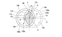
- FIG. 3 is a cross-sectional view showing an intermediate shaft portion in a rotation shaft of a rotary compressor according to an embodiment of the present invention, and a view showing an AA cross section of FIG. 2;
- Graph of experimental results showing the relationship between the load direction (maximum gas load direction) of refrigerant gas during compression acting on the rotary shaft of the rotary compressor according to the embodiment of the present invention and the load (maximum gas load) by the refrigerant gas It is.
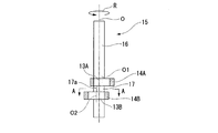
- the rotary compressor 1 includes a drive unit 18, a rotary shaft 15 rotationally driven by the drive unit 18, and a casing 11 accommodating the drive unit 18 and the rotary shaft 15.
- the rotary compressor 1 is a so-called two-cylinder type rotary compressor 1 in which compression chambers S are provided in upper and lower two stages at an inner lower portion of a casing 11.
- the casing 11 has a cylindrical shape centering on the axis O, and two disk-shaped cylinders 12A and 12B are provided at the lower part inside the casing 11 at intervals in the vertical direction.
- the upper cylinder is a main shaft cylinder 12A
- the lower cylinder is a secondary shaft cylinder 12B.
- cylindrical inner wall surfaces 12S1 and 12S2 are formed inside the cylinders 12A and 12B.
- a first compression chamber S1 is defined by the cylinder inner wall surface 12S1 of the main spindle side cylinder 12A
- a second compression chamber S2 is defined by the cylinder inner wall surface 12S2 of the countershaft side cylinder 12B.
- a disk-shaped partition plate 10 is provided between the upper and lower cylinders 12A and 12B. The first compression chamber S1 and the second compression chamber S2 are partitioned by the partition plate 10.
- Openings 22A and 22B are formed on the side surface of the casing 11, that is, on the outer peripheral surface, at positions facing the outer peripheral surfaces of the main shaft side cylinder 12A and the sub shaft side cylinder 12B.
- Suction ports 23A, 23B communicating with the first compression chamber S1 and the second compression chamber S2 are formed in the respective cylinders 12A, 12B at positions opposed to the openings 22A, 22B.
- an accumulator 24 for performing gas-liquid separation of the refrigerant taken in from the upper suction port 24a is fixed to the casing 11 via a stay 25.
- the accumulator 24 is provided with suction pipes 26A, 26B for introducing the gas phase of the refrigerant separated by the accumulator 24 into the first compression chamber S1 and the second compression chamber S2 in the casing 11.
- the tips of the suction pipes 26A, 26B are connected to the suction ports 23A, 23B through the openings 22A, 22B.
- a discharge port 27 for discharging the refrigerant compressed in the first compression chamber S1 and the second compression chamber S2 is provided.
- the drive unit 18 is an electric motor, and includes a stator 20 fixed to the inner surface of the casing 11 above the main shaft side cylinder 12A, and a rotor 19 disposed to face the stator 20 inside the stator 20. ing.
- the rotary shaft 15 has a rod-like shaft main body 16 extending in the direction of the axis O about the axis O, a main shaft piston rotor 14A and a sub shaft piston rotor 14B provided on the shaft main body 16, and a main shaft An intermediate shaft portion 17 is disposed at a position between the piston rotor 14A and the countershaft piston rotor 14B in the direction of the axis O.
- the shaft main body 16 is provided by being fitted into the rotor 19 of the drive unit 18, and rotates around the axis O together with the rotor 19 by the power supply to the drive unit 18.
- the shaft main body 16 is rotatably supported by the casing 11 by an upper bearing 17A provided at an upper portion of the main shaft side cylinder 12A and a lower bearing 17B provided at a lower portion of the auxiliary shaft side cylinder 12B.
- the main shaft piston rotor 14A is provided in the shaft main body 16 and accommodated in the first compression chamber S1, and rotates around the axis O together with the shaft main body 16.
- the main shaft piston rotor 14A is integrally formed with the shaft main body 16, and is externally fitted to a cylindrical main shaft side eccentric shaft portion 13A centered on the eccentric axis O1 parallel to the axis O and has an annular shape. .
- the main shaft piston rotor 14A eccentrically rotates with respect to the shaft main body 16.
- the countershaft piston rotor 14B is provided on the shaft main body 16 and accommodated in the second compression chamber S2, and rotates around the axis O together with the shaft main body 16.
- the countershaft piston rotor 14B is integrally formed with the shaft main body 16, and is externally fitted to the countershaft side eccentric shaft 13B having a cylindrical shape centering on the eccentric axis O2 parallel to the axis O and the eccentric axis O1. , Has a ring.
- the eccentric axis O2 is disposed at a position symmetrical to the eccentric axis O1 with respect to the axis O. That is, the main-shaft piston rotor 14A and the sub-shaft piston rotor 14B rotate in a state where they are eccentric with respect to the shaft main body 16 in directions different in phase by 180 degrees.
- the rotary shaft 15 may be formed separately by manufacturing separately the main shaft portion provided with the main shaft piston rotor 14A and the counter shaft portion provided with the counter shaft piston rotor 14B, or integrally formed You may The main shaft portion and the counter shaft portion may have different outer diameters.
- the intermediate shaft portion 17 will be described. As shown in FIG. 2, the intermediate shaft portion 17 is provided at a position where it is sandwiched in the direction of the axis O by the main shaft piston rotor 14A and the counter shaft piston rotor 14B. That is, the intermediate shaft portion 17 is disposed in the casing 11 between the main shaft side cylinder 12A and the sub shaft side cylinder 12B.
- the outer peripheral surface of the intermediate shaft portion 17 is the outer peripheral edge 14Aa of the main shaft piston rotor 14A and the outer peripheral edge of the auxiliary shaft piston rotor 14B. It is disposed in one area AR overlapping with 14Ba. More specifically, in the present embodiment, the outer peripheral edge 13Aa of the main shaft side eccentric shaft portion 13A and the outer peripheral edge 13Ba of the countershaft side eccentric shaft portion 13B are disposed in the overlapping region.
- the cross-sectional shape of the intermediate shaft portion 17 has a substantially oval shape, a rugby ball shape, or an almond shape.
- the intermediate shaft portion 17 is a pair that is convex on both sides in a direction intersecting the eccentric direction in which the imaginary line X connecting the eccentric axes O1 and O2 and the axis O extends over the entire region in the direction of the axis O
- the pair of apexes 17 a are provided at symmetrical positions with respect to the axis O. Each of the apexes 17a is disposed at a position shifted by an angle ⁇ to the rear side of the rotational direction R of the rotation shaft 15 with respect to an imaginary line Y extending in a direction orthogonal to the eccentric direction.
- the outer diameter dimension of the intermediate shaft portion 17 is the largest. Further, the outer diameter dimension of the intermediate shaft portion 17 is the smallest in the eccentric direction.
- the outer peripheral surface of the top 17a is disposed at a position distant from the outer peripheral edge 13Aa, 13Ba which is the outer edge of the one area AR, that is, radially inward of the outer edge, from the top 17a toward the front in the rotational direction R It has an arc-shaped top side curved surface 17b that curves in a convex shape in a direction away from it and an arc-shaped eccentric side curved surface 17c that continues to the top 17a.
- a pair of apex side curved surfaces 17b are provided at symmetrical positions with respect to the axis O.
- the radius of curvature of the top curved surface 17b is preferably as large as possible in order to keep the second moment of area of the intermediate shaft portion 17 large.
- the eccentric-side curved surface 17c is smoothly continuous with the top-side curved surface 17b with no corners in front of the top 17a in the direction of rotation.
- the eccentric-side curved surface 17c is provided at a position including the intersection P of the imaginary line X extending in the eccentric direction and the outer edge of the one area AR, and extends along the outer edge on the outer edge.
- a pair of eccentric side curved surfaces 17c at symmetrical positions with respect to the axis O is provided.
- one eccentric-side curved surface 17c extends along the outer edge of one area AR continuously in the rotational direction R forward to one top-side curved surface 17b extending forward in the rotational direction R from one apex 17a, Connected to the top 17a of the
- the other eccentric-side curved surface 17c is continuous with the other top-side curved surface 17b extending forward in the rotational direction R from the other top 17a in the rotational direction R forward and extends along the outer edge of the one area AR Connected to 17a.
- the middle shaft portion 17 has a top side curved surface 17b, and the middle shaft portion 17 has a substantially oval shape, a rugby ball shape, or an almond shape, and a part in the rotational direction of the top portion 17a is radially inward. It has a shape that has been scraped away.
- the center of the processing circle is disposed on the rear side in the rotational direction R of the rotation axis 15 with respect to the imaginary line Y, It is possible to cut the intermediate shaft portion 17 in an arc shape.
- the angle ⁇ from the imaginary line Y to the connection point between the top side curved surface 17b, the top side curved surface 17b, and the eccentric side curved surface 17c continuing forward in the rotational direction R is a value larger than the angle ⁇ ( ⁇ ⁇ ), ⁇ should be as close to ⁇ as possible.
- the value of the angle ⁇ is, for example, a value larger than 0 degrees and smaller than 5 degrees in the present embodiment.
- HP / LP in Table 1 was set supposing HP / LP in a common air conditioner.
- the diameter of the intermediate shaft 17 is largest at the position where the top 17a is provided, the second moment of area of the intermediate shaft 17 can be increased at this position, and the rigidity of the intermediate shaft 17 can be improved. . Therefore, even when the load at the time of compression acts on each piston rotor 14A, 14B, it becomes possible to suppress the bending deformation of the rotating shaft 15.
- the apex 17a is disposed at a position that is offset by an angle ⁇ that is greater than 0 degrees and less than 5 degrees on the rear side of the rotational direction R with respect to the direction orthogonal to the eccentric direction.
- the thickness of the intermediate shaft portion 17 on the front side in the rotational direction R is smaller than that of a cylindrical shape.
- the load acting at the time of compression is smaller than the maximum load at the portion where the thickness of the intermediate shaft portion 17 is narrowed, the intermediate shaft is provided even if the apex 17a is provided at the above position.
- the strength of the portion 17 can be secured sufficiently. And weight reduction of the intermediate shaft part 17 can also be achieved.
- the outer peripheral surface of the intermediate shaft portion 17 is disposed in a region AR where the outer peripheral edge of the main shaft piston rotor 14A and the outer peripheral edge of the auxiliary shaft piston rotor 14B overlap, and the outer peripheral surface of the intermediate shaft portion 17
- the top 17a is formed to be scraped off on the front side in the rotational direction R of the top 17a. For this reason, when the rotating shaft 15 rotates, the lubricating oil present around the intermediate shaft portion 17 is smoothly guided toward the top portion 17 a of the intermediate shaft portion 17, and the intermediate shaft portion toward the rear in the rotational direction R Smoothly circulates on the outer circumferential surface of 17. Therefore, it is possible to reduce the stirring loss when the lubricating oil is stirred by the intermediate shaft portion 17 at the time of rotation.
- the above intersection point is formed on the outer peripheral surface of the intermediate shaft 17 on the front side of the top 17a in the rotational direction R.
- a smooth curved surface having no corners from P to the top 17a is formed. Therefore, when the lubricating oil is stirred by the rotating shaft 15, the lubricating oil is guided to these surfaces from the eccentric-side curved surface 17c to the top-side curved surface 17b and flows smoothly. Therefore, even with the intermediate shaft portion 17 having the top portion 17a, the stirring loss of the lubricating oil can be reduced.
- the lubricating oil is guided smoothly on the outer peripheral surface of the intermediate shaft 17 while securing the strength of the intermediate shaft 17, and the stirring loss of the lubricating oil Can be further reduced. Furthermore, when rotating, the centrifugal force acting on the position of the top 17a of the intermediate shaft 17 can be canceled by the tops 17a to improve the stability of the rotating shaft 15 when it is rotating.
- the embodiments of the present invention have been described in detail with reference to the drawings, but the respective configurations and the combinations thereof and the like in the respective embodiments are merely examples, and additions and omissions of configurations are possible within the scope of the present invention. , Substitution, and other changes are possible. Further, the present invention is not limited by the embodiments, and is limited only by the scope of claims.
- the top 17a may be provided only in one place.
- the apex 17a is disposed at a position deviated by an angle ⁇ of more than 0 degrees and less than 5 degrees behind the rotational direction R with respect to the imaginary line Y orthogonal to the eccentric direction.
- the pair of apexes 17a is provided, and the positions where the apexes 17a are disposed are the angles ⁇ 1 and ⁇ 2 behind the rotational direction R with respect to the imaginary line Y orthogonal to the eccentric direction. It is arranged at the shifted position.
- the angles ⁇ 1 and ⁇ 2 are different from each other, and both are angles larger than 0 ° and smaller than 5 ° behind the rotational direction R with respect to the imaginary line Y orthogonal to the eccentric direction.
- top curved surface 17b of the intermediate shaft portion 17 is not limited to the arc-shaped curved surface, and may be formed, for example, in a planar shape.
- the top 17a may be disposed outside the one area AR.
- angles ⁇ , ⁇ , ⁇ 1 and ⁇ 2 described above are, for example, values larger than 0 degrees and smaller than 5 degrees
- the present invention is not limited thereto. That is, since it is only necessary to position the top 17a where the distance to the axis O is the largest at the position where the maximum load acts on the intermediate shaft 17, the values of ⁇ , ⁇ , ⁇ 1 and ⁇ 2 are larger than 0 degree and smaller than 45 degrees It only needs to be done. In particular, in the case where the top 17a is disposed outside the one area AR, the diameter of the intermediate shaft 17 does not become extremely small at the rear of the rotation direction R of the top 17a. It is not necessary to limit the values of ⁇ , ⁇ , ⁇ 1 and ⁇ 2 to values larger than 0 ° and smaller than 5 ° as described above.
- the deflection of the rotary shaft can be suppressed and the efficiency can be improved by the above configuration.
- Rotary compressor 10 Partition plate 11: Casing 12A: Main shaft side cylinder 12B: Secondary shaft side cylinder 12S1, 12S2: Cylinder inner wall surface 13A: Main shaft side eccentric shaft 13B: Secondary shaft side eccentric shaft 13Aa, 13Ba: Outside Peripheral edge 14A: Main shaft piston rotor 14B: Countershaft piston rotor 14Aa, 14Ba: Outer peripheral edge 15: Rotating shaft 16: Shaft main body 18: Drive portion 17: Intermediate shaft portion 17a: Top portion 17b: Top portion side curved surface 17c: Eccentric side curved surface 19: Rotor 20: Stator 22A: opening 22B: opening 23A: suction port 23B: suction port 24: accumulator 24a: suction port 25: stay 26A: suction pipe 26B: suction pipe 27: discharge port S: compression chamber S1: first compression chamber S2 ... second compression chamber R ... rotation direction O ... axis line O1 ... eccentric axis O2
Landscapes
- Engineering & Computer Science (AREA)
- Mechanical Engineering (AREA)
- General Engineering & Computer Science (AREA)
- Applications Or Details Of Rotary Compressors (AREA)
Abstract
Priority Applications (3)
| Application Number | Priority Date | Filing Date | Title |
|---|---|---|---|
| AU2018352907A AU2018352907B2 (en) | 2017-10-18 | 2018-10-18 | Rotating shaft of rotary compressor and rotary compressor |
| EP18867363.6A EP3677784B1 (fr) | 2017-10-18 | 2018-10-18 | Arbre rotatif de compresseur rotatif, et compresseur rotatif |
| CN201880067557.3A CN111226039B (zh) | 2017-10-18 | 2018-10-18 | 旋转式压缩机的旋转轴及旋转式压缩机 |
Applications Claiming Priority (2)
| Application Number | Priority Date | Filing Date | Title |
|---|---|---|---|
| JP2017-201554 | 2017-10-18 | ||
| JP2017201554A JP6350843B1 (ja) | 2017-10-18 | 2017-10-18 | ロータリ圧縮機の回転軸、及び、ロータリ圧縮機 |
Publications (1)
| Publication Number | Publication Date |
|---|---|
| WO2019078293A1 true WO2019078293A1 (fr) | 2019-04-25 |
Family
ID=62779892
Family Applications (1)
| Application Number | Title | Priority Date | Filing Date |
|---|---|---|---|
| PCT/JP2018/038818 Ceased WO2019078293A1 (fr) | 2017-10-18 | 2018-10-18 | Arbre rotatif de compresseur rotatif, et compresseur rotatif |
Country Status (5)
| Country | Link |
|---|---|
| EP (1) | EP3677784B1 (fr) |
| JP (1) | JP6350843B1 (fr) |
| CN (1) | CN111226039B (fr) |
| AU (1) | AU2018352907B2 (fr) |
| WO (1) | WO2019078293A1 (fr) |
Families Citing this family (2)
| Publication number | Priority date | Publication date | Assignee | Title |
|---|---|---|---|---|
| CN111486091B (zh) * | 2019-11-21 | 2023-12-08 | 山东青耕电气有限公司 | 单缸转子式液体高频换向装置及其压缩机 |
| CN117469160A (zh) * | 2023-11-06 | 2024-01-30 | 广东美芝精密制造有限公司 | 压缩组件、压缩机和制冷设备 |
Citations (4)
| Publication number | Priority date | Publication date | Assignee | Title |
|---|---|---|---|---|
| WO2009028633A1 (fr) * | 2007-08-28 | 2009-03-05 | Toshiba Carrier Corporation | Compresseur de type rotatif à cylindres multiples et appareil de cycles de réfrigération |
| JP2013096280A (ja) * | 2011-10-31 | 2013-05-20 | Mitsubishi Electric Corp | 回転圧縮機 |
| JP2013181420A (ja) | 2012-02-29 | 2013-09-12 | Fujitsu General Ltd | ロータリ圧縮機 |
| JP2017201554A (ja) | 2017-07-04 | 2017-11-09 | 株式会社デンソーウェーブ | 据置型情報コード読取装置 |
Family Cites Families (6)
| Publication number | Priority date | Publication date | Assignee | Title |
|---|---|---|---|---|
| JP3723408B2 (ja) * | 1999-08-31 | 2005-12-07 | 三洋電機株式会社 | 2シリンダ型2段圧縮ロータリーコンプレッサ |
| JP4065654B2 (ja) * | 2000-10-30 | 2008-03-26 | 日立アプライアンス株式会社 | 複数シリンダロータリ圧縮機 |
| JP4380054B2 (ja) * | 2000-10-30 | 2009-12-09 | 株式会社日立製作所 | 2シリンダロータリ型圧縮機 |
| JP2006177228A (ja) * | 2004-12-22 | 2006-07-06 | Hitachi Home & Life Solutions Inc | ロータリ2段圧縮機及びそれを用いた空気調和機 |
| JP2009028633A (ja) * | 2007-07-26 | 2009-02-12 | Panasonic Corp | 洗浄方法 |
| JP6076643B2 (ja) * | 2012-07-31 | 2017-02-08 | 三菱重工業株式会社 | ロータリ流体機械及びその組立方法 |
-
2017
- 2017-10-18 JP JP2017201554A patent/JP6350843B1/ja active Active
-
2018
- 2018-10-18 CN CN201880067557.3A patent/CN111226039B/zh active Active
- 2018-10-18 AU AU2018352907A patent/AU2018352907B2/en active Active
- 2018-10-18 EP EP18867363.6A patent/EP3677784B1/fr active Active
- 2018-10-18 WO PCT/JP2018/038818 patent/WO2019078293A1/fr not_active Ceased
Patent Citations (4)
| Publication number | Priority date | Publication date | Assignee | Title |
|---|---|---|---|---|
| WO2009028633A1 (fr) * | 2007-08-28 | 2009-03-05 | Toshiba Carrier Corporation | Compresseur de type rotatif à cylindres multiples et appareil de cycles de réfrigération |
| JP2013096280A (ja) * | 2011-10-31 | 2013-05-20 | Mitsubishi Electric Corp | 回転圧縮機 |
| JP2013181420A (ja) | 2012-02-29 | 2013-09-12 | Fujitsu General Ltd | ロータリ圧縮機 |
| JP2017201554A (ja) | 2017-07-04 | 2017-11-09 | 株式会社デンソーウェーブ | 据置型情報コード読取装置 |
Non-Patent Citations (1)
| Title |
|---|
| See also references of EP3677784A4 |
Also Published As
| Publication number | Publication date |
|---|---|
| CN111226039A (zh) | 2020-06-02 |
| AU2018352907B2 (en) | 2021-06-10 |
| JP6350843B1 (ja) | 2018-07-04 |
| EP3677784A1 (fr) | 2020-07-08 |
| CN111226039B (zh) | 2022-03-08 |
| JP2019074047A (ja) | 2019-05-16 |
| AU2018352907A1 (en) | 2020-04-23 |
| EP3677784A4 (fr) | 2020-09-09 |
| EP3677784B1 (fr) | 2025-04-02 |
| EP3677784C0 (fr) | 2025-04-02 |
Similar Documents
| Publication | Publication Date | Title |
|---|---|---|
| JP4962585B2 (ja) | 回転式圧縮機 | |
| KR101375979B1 (ko) | 회전 압축기 | |
| JP5781019B2 (ja) | ロータリ式圧縮機 | |
| JP4889677B2 (ja) | 並列ロータリ圧縮機 | |
| JPH0458086A (ja) | 流体圧縮機 | |
| WO2019078293A1 (fr) | Arbre rotatif de compresseur rotatif, et compresseur rotatif | |
| JP7067880B2 (ja) | 圧縮機 | |
| CN203560100U (zh) | 旋转式压缩机和具有该旋转式压缩机的空调设备 | |
| JP7014544B2 (ja) | オルダムリング、スクロール圧縮機 | |
| JP2007023776A (ja) | スクロール流体機械 | |
| JP6922077B2 (ja) | ロータリコンプレッサおよび冷凍サイクル装置 | |
| US20210017984A1 (en) | Rotary compressor | |
| WO2011052166A1 (fr) | Machine à fluide à spirale | |
| JP2020186660A (ja) | ロータリ圧縮機 | |
| WO2020208765A1 (fr) | Compresseur à spirale | |
| JP2016089650A (ja) | ロータリ圧縮機 | |
| CN112292531B (zh) | 涡旋压缩机 | |
| JP2019094844A (ja) | ロータリ圧縮機 | |
| JP2021076067A (ja) | ロータリ圧縮機 | |
| JPH10184570A (ja) | スクロール流体機械 | |
| JP2020193567A (ja) | ロータリ圧縮機 | |
| JP2009115055A (ja) | 回転式流体機械 | |
| WO2013179677A1 (fr) | Compresseur rotatif | |
| JP2006132504A (ja) | スクロール型圧縮機並びにこれを備えた燃料電池システム | |
| JPH1054378A (ja) | スクロール流体機械 |
Legal Events
| Date | Code | Title | Description |
|---|---|---|---|
| 121 | Ep: the epo has been informed by wipo that ep was designated in this application |
Ref document number: 18867363 Country of ref document: EP Kind code of ref document: A1 |
|
| ENP | Entry into the national phase |
Ref document number: 2018867363 Country of ref document: EP Effective date: 20200330 |
|
| NENP | Non-entry into the national phase |
Ref country code: DE |
|
| ENP | Entry into the national phase |
Ref document number: 2018352907 Country of ref document: AU Date of ref document: 20181018 Kind code of ref document: A |
|
| WWG | Wipo information: grant in national office |
Ref document number: 2018867363 Country of ref document: EP |