WO2019078536A1 - 유기 광전자 소자용 조성물, 유기 광전자 소자 및 표시 장치 - Google Patents
유기 광전자 소자용 조성물, 유기 광전자 소자 및 표시 장치 Download PDFInfo
- Publication number
- WO2019078536A1 WO2019078536A1 PCT/KR2018/011898 KR2018011898W WO2019078536A1 WO 2019078536 A1 WO2019078536 A1 WO 2019078536A1 KR 2018011898 W KR2018011898 W KR 2018011898W WO 2019078536 A1 WO2019078536 A1 WO 2019078536A1
- Authority
- WO
- WIPO (PCT)
- Prior art keywords
- group
- substituted
- unsubstituted
- independently
- formula
- Prior art date
- Legal status (The legal status is an assumption and is not a legal conclusion. Google has not performed a legal analysis and makes no representation as to the accuracy of the status listed.)
- Ceased
Links
- 0 CCCc1[n+](CC)c(*N)[n+]c(C)n1 Chemical compound CCCc1[n+](CC)c(*N)[n+]c(C)n1 0.000 description 2
- QFRLJHQZIDNWGW-UHFFFAOYSA-Q CCCc1[nH+]c(C)[nH+]c(C)[nH+]1 Chemical compound CCCc1[nH+]c(C)[nH+]c(C)[nH+]1 QFRLJHQZIDNWGW-UHFFFAOYSA-Q 0.000 description 1
Classifications
-
- C—CHEMISTRY; METALLURGY
- C09—DYES; PAINTS; POLISHES; NATURAL RESINS; ADHESIVES; COMPOSITIONS NOT OTHERWISE PROVIDED FOR; APPLICATIONS OF MATERIALS NOT OTHERWISE PROVIDED FOR
- C09K—MATERIALS FOR MISCELLANEOUS APPLICATIONS, NOT PROVIDED FOR ELSEWHERE
- C09K11/00—Luminescent materials, e.g. electroluminescent or chemiluminescent
- C09K11/06—Luminescent materials, e.g. electroluminescent or chemiluminescent containing organic luminescent materials
-
- H—ELECTRICITY
- H10—SEMICONDUCTOR DEVICES; ELECTRIC SOLID-STATE DEVICES NOT OTHERWISE PROVIDED FOR
- H10K—ORGANIC ELECTRIC SOLID-STATE DEVICES
- H10K50/00—Organic light-emitting devices
- H10K50/10—OLEDs or polymer light-emitting diodes [PLED]
- H10K50/11—OLEDs or polymer light-emitting diodes [PLED] characterised by the electroluminescent [EL] layers
- H10K50/12—OLEDs or polymer light-emitting diodes [PLED] characterised by the electroluminescent [EL] layers comprising dopants
-
- H—ELECTRICITY
- H10—SEMICONDUCTOR DEVICES; ELECTRIC SOLID-STATE DEVICES NOT OTHERWISE PROVIDED FOR
- H10K—ORGANIC ELECTRIC SOLID-STATE DEVICES
- H10K77/00—Constructional details of devices covered by this subclass and not covered by groups H10K10/80, H10K30/80, H10K50/80 or H10K59/80
-
- H—ELECTRICITY
- H10—SEMICONDUCTOR DEVICES; ELECTRIC SOLID-STATE DEVICES NOT OTHERWISE PROVIDED FOR
- H10K—ORGANIC ELECTRIC SOLID-STATE DEVICES
- H10K85/00—Organic materials used in the body or electrodes of devices covered by this subclass
- H10K85/60—Organic compounds having low molecular weight
- H10K85/649—Aromatic compounds comprising a hetero atom
- H10K85/653—Aromatic compounds comprising a hetero atom comprising only oxygen as heteroatom
-
- H—ELECTRICITY
- H10—SEMICONDUCTOR DEVICES; ELECTRIC SOLID-STATE DEVICES NOT OTHERWISE PROVIDED FOR
- H10K—ORGANIC ELECTRIC SOLID-STATE DEVICES
- H10K85/00—Organic materials used in the body or electrodes of devices covered by this subclass
- H10K85/60—Organic compounds having low molecular weight
- H10K85/649—Aromatic compounds comprising a hetero atom
- H10K85/654—Aromatic compounds comprising a hetero atom comprising only nitrogen as heteroatom
-
- H—ELECTRICITY
- H10—SEMICONDUCTOR DEVICES; ELECTRIC SOLID-STATE DEVICES NOT OTHERWISE PROVIDED FOR
- H10K—ORGANIC ELECTRIC SOLID-STATE DEVICES
- H10K85/00—Organic materials used in the body or electrodes of devices covered by this subclass
- H10K85/60—Organic compounds having low molecular weight
- H10K85/649—Aromatic compounds comprising a hetero atom
- H10K85/655—Aromatic compounds comprising a hetero atom comprising only sulfur as heteroatom
-
- H—ELECTRICITY
- H10—SEMICONDUCTOR DEVICES; ELECTRIC SOLID-STATE DEVICES NOT OTHERWISE PROVIDED FOR
- H10K—ORGANIC ELECTRIC SOLID-STATE DEVICES
- H10K85/00—Organic materials used in the body or electrodes of devices covered by this subclass
- H10K85/60—Organic compounds having low molecular weight
- H10K85/649—Aromatic compounds comprising a hetero atom
- H10K85/657—Polycyclic condensed heteroaromatic hydrocarbons
-
- H—ELECTRICITY
- H10—SEMICONDUCTOR DEVICES; ELECTRIC SOLID-STATE DEVICES NOT OTHERWISE PROVIDED FOR
- H10K—ORGANIC ELECTRIC SOLID-STATE DEVICES
- H10K85/00—Organic materials used in the body or electrodes of devices covered by this subclass
- H10K85/60—Organic compounds having low molecular weight
- H10K85/649—Aromatic compounds comprising a hetero atom
- H10K85/657—Polycyclic condensed heteroaromatic hydrocarbons
- H10K85/6572—Polycyclic condensed heteroaromatic hydrocarbons comprising only nitrogen in the heteroaromatic polycondensed ring system, e.g. phenanthroline or carbazole
-
- H—ELECTRICITY
- H10—SEMICONDUCTOR DEVICES; ELECTRIC SOLID-STATE DEVICES NOT OTHERWISE PROVIDED FOR
- H10K—ORGANIC ELECTRIC SOLID-STATE DEVICES
- H10K85/00—Organic materials used in the body or electrodes of devices covered by this subclass
- H10K85/60—Organic compounds having low molecular weight
- H10K85/649—Aromatic compounds comprising a hetero atom
- H10K85/657—Polycyclic condensed heteroaromatic hydrocarbons
- H10K85/6574—Polycyclic condensed heteroaromatic hydrocarbons comprising only oxygen in the heteroaromatic polycondensed ring system, e.g. cumarine dyes
-
- H—ELECTRICITY
- H10—SEMICONDUCTOR DEVICES; ELECTRIC SOLID-STATE DEVICES NOT OTHERWISE PROVIDED FOR
- H10K—ORGANIC ELECTRIC SOLID-STATE DEVICES
- H10K85/00—Organic materials used in the body or electrodes of devices covered by this subclass
- H10K85/60—Organic compounds having low molecular weight
- H10K85/649—Aromatic compounds comprising a hetero atom
- H10K85/657—Polycyclic condensed heteroaromatic hydrocarbons
- H10K85/6576—Polycyclic condensed heteroaromatic hydrocarbons comprising only sulfur in the heteroaromatic polycondensed ring system, e.g. benzothiophene
-
- C—CHEMISTRY; METALLURGY
- C09—DYES; PAINTS; POLISHES; NATURAL RESINS; ADHESIVES; COMPOSITIONS NOT OTHERWISE PROVIDED FOR; APPLICATIONS OF MATERIALS NOT OTHERWISE PROVIDED FOR
- C09K—MATERIALS FOR MISCELLANEOUS APPLICATIONS, NOT PROVIDED FOR ELSEWHERE
- C09K2211/00—Chemical nature of organic luminescent or tenebrescent compounds
- C09K2211/10—Non-macromolecular compounds
- C09K2211/1018—Heterocyclic compounds
- C09K2211/1025—Heterocyclic compounds characterised by ligands
- C09K2211/1029—Heterocyclic compounds characterised by ligands containing one nitrogen atom as the heteroatom
-
- C—CHEMISTRY; METALLURGY
- C09—DYES; PAINTS; POLISHES; NATURAL RESINS; ADHESIVES; COMPOSITIONS NOT OTHERWISE PROVIDED FOR; APPLICATIONS OF MATERIALS NOT OTHERWISE PROVIDED FOR
- C09K—MATERIALS FOR MISCELLANEOUS APPLICATIONS, NOT PROVIDED FOR ELSEWHERE
- C09K2211/00—Chemical nature of organic luminescent or tenebrescent compounds
- C09K2211/10—Non-macromolecular compounds
- C09K2211/1018—Heterocyclic compounds
- C09K2211/1025—Heterocyclic compounds characterised by ligands
- C09K2211/1059—Heterocyclic compounds characterised by ligands containing three nitrogen atoms as heteroatoms
-
- C—CHEMISTRY; METALLURGY
- C09—DYES; PAINTS; POLISHES; NATURAL RESINS; ADHESIVES; COMPOSITIONS NOT OTHERWISE PROVIDED FOR; APPLICATIONS OF MATERIALS NOT OTHERWISE PROVIDED FOR
- C09K—MATERIALS FOR MISCELLANEOUS APPLICATIONS, NOT PROVIDED FOR ELSEWHERE
- C09K2211/00—Chemical nature of organic luminescent or tenebrescent compounds
- C09K2211/10—Non-macromolecular compounds
- C09K2211/1018—Heterocyclic compounds
- C09K2211/1025—Heterocyclic compounds characterised by ligands
- C09K2211/1088—Heterocyclic compounds characterised by ligands containing oxygen as the only heteroatom
-
- H—ELECTRICITY
- H10—SEMICONDUCTOR DEVICES; ELECTRIC SOLID-STATE DEVICES NOT OTHERWISE PROVIDED FOR
- H10K—ORGANIC ELECTRIC SOLID-STATE DEVICES
- H10K2101/00—Properties of the organic materials covered by group H10K85/00
- H10K2101/10—Triplet emission
-
- H—ELECTRICITY
- H10—SEMICONDUCTOR DEVICES; ELECTRIC SOLID-STATE DEVICES NOT OTHERWISE PROVIDED FOR
- H10K—ORGANIC ELECTRIC SOLID-STATE DEVICES
- H10K2101/00—Properties of the organic materials covered by group H10K85/00
- H10K2101/90—Multiple hosts in the emissive layer
-
- H—ELECTRICITY
- H10—SEMICONDUCTOR DEVICES; ELECTRIC SOLID-STATE DEVICES NOT OTHERWISE PROVIDED FOR
- H10K—ORGANIC ELECTRIC SOLID-STATE DEVICES
- H10K50/00—Organic light-emitting devices
- H10K50/10—OLEDs or polymer light-emitting diodes [PLED]
- H10K50/11—OLEDs or polymer light-emitting diodes [PLED] characterised by the electroluminescent [EL] layers
-
- Y—GENERAL TAGGING OF NEW TECHNOLOGICAL DEVELOPMENTS; GENERAL TAGGING OF CROSS-SECTIONAL TECHNOLOGIES SPANNING OVER SEVERAL SECTIONS OF THE IPC; TECHNICAL SUBJECTS COVERED BY FORMER USPC CROSS-REFERENCE ART COLLECTIONS [XRACs] AND DIGESTS
- Y02—TECHNOLOGIES OR APPLICATIONS FOR MITIGATION OR ADAPTATION AGAINST CLIMATE CHANGE
- Y02E—REDUCTION OF GREENHOUSE GAS [GHG] EMISSIONS, RELATED TO ENERGY GENERATION, TRANSMISSION OR DISTRIBUTION
- Y02E10/00—Energy generation through renewable energy sources
- Y02E10/50—Photovoltaic [PV] energy
- Y02E10/549—Organic PV cells
Definitions
- compositions for organic optoelectronic devices for organic optoelectronic devices, organic optoelectronic devices and display devices
- a composition for organic optoelectronic devices, an organic optoelectronic device and a display device is provided.
- An organic optoelectronic diode is an element that can switch between electric energy and light energy.
- Organic optoelectronic devices can be roughly classified into two types according to the operating principle.
- One is an optoelectronic device in which an exciton formed by light energy is separated into an electron and a hole, the electron and hole are transferred to different electrodes to generate electric energy, and the other is a voltage /
- Emitting device that generates light energy from energy.
- organic optoelectronic devices examples include organic optoelectronic devices, organic light emitting devices, organic solar cells, and organic photo conductor drums.
- the organic light emitting diode is a device for converting electrical energy into light by applying an electric current to the organic light emitting material, and usually has an organic layer inserted between an anode and a cathode.
- the organic layer may include a light emitting layer and an optional auxiliary layer.
- the auxiliary layer may include, for example, a hole injecting layer, a hole transporting layer, an electron blocking layer, an electron transporting layer, Layer and a hole blocking layer.
- the performance of the organic light emitting device is greatly influenced by the characteristics of the organic layer, and the organic layer is highly affected by the organic material contained in the organic layer.
- One embodiment provides a composition for a optoelectronic device capable of realizing a highly efficient and long-lived organic optoelectronic device.
- Another embodiment provides an organic optoelectronic device comprising the composition.
- Another embodiment provides a display device comprising the organic opto-electronic device.
- a compound for an organic optoelectronic device represented by a combination of the following general formulas (1) and (2); And compounds for organic electroluminescent devices represented by Formula 3 below.
- Ar 1 and Ar 2 are each independently a substituted or unsubstituted C6 to C30 aryl group
- R 1 to R 3 are each independently hydrogen, deuterium or cyano group, and two adjacent * in Formula 1 are linked to * in Formula 2 and are not connected to * in Formula 2, Are each independently CR a ,
- Z 1 to Z 3 are each independently N or CR b ,
- At least two of Z 1 to Z 3 are N,
- R a , R b and R 4 to R 6 are each independently selected from the group consisting of hydrogen, deuterium, cyano, substituted or unsubstituted C1 to C10 alkyl groups, substituted or unsubstituted C6 to C20 aryl groups, A C2 to C30 heterocyclic group,
- L 1 to L 5 are each independently a single bond or a substituted or unsubstituted C6 to C30 arylene group
- X < 1 > is O or S
- a 1 and A 2 are each independently a substituted or unsubstituted C6 to C20 aryl group or a substituted or unsubstituted C2 to C30 heterocyclic group.
- an organic optoelectronic device including an anode and a cathode facing each other, and at least one organic layer positioned between the anode and the cathode, wherein the organic layer includes the composition for the organic optoelectronic device .
- a display device including the organic optoelectronic device.
- FIG. 1 and 2 are cross-sectional views illustrating an organic light emitting device according to one embodiment.
- At least one hydrogen in the substituent or compound is replaced with a substituent selected from the group consisting of deuterium, a halogen group, a hydroxyl group, an amino group, a substituted or unsubstituted C1 to C30 amine group, Or an unsubstituted C1 to C40 silyl group, a C1 to C30 alkyl group, a C1 to C10 alkylsilyl group, a C6 to C30 arylsilyl group, a C3 to C30 cycloalkyl group, a C3 to C30 heterocycloalkyl group, a C6 to C30 aryl group, C30 heteroaryl groups, C1 to C20 alkoxy groups, C1 to C10 tree means substituted by fluoro group, a cyano group, or a combination thereof.
- a substituent selected from the group consisting of deuterium, a halogen group, a hydroxyl group, an amino group, a substituted or un
- the “substituted in one example of the invention” is a substituent or at least one compound increasing C30 aryl group, a C3 to C30 cycloalkyl group, a C3 to C30 heterocycloalkyl group, a C6 to C30 aryl group, a C1 to C30 alkyl group, Group and a C2 to C30 heteroaryl group.
- "substituted” means that at least one hydrogen of the substituent or compound is substituted with deuterium, a C1 to C20 alkyl group, a C6 to C30 aryl group, or a C2 to C30 heteroaryl group.
- substituted means that at least one hydrogen in the substituent or compound is substituted with deuterium, a C1 to C5 alkyl group, a C6 to C18 aryl group, a dibenzofuranyl group, or a dibenzothiophenyl group .
- substituted means that at least one hydrogen in the substituent or compound is substituted with one or more groups selected from the group consisting of deuterium, methyl, ethyl, propanyl, butyl, phenyl, biphenyl, terphenyl, Oleyl group,
- a dibenzofuranyl group or a dibenzothiophenyl group is A dibenzofuranyl group or a dibenzothiophenyl group.
- alkyl group means an aliphatic hydrocarbon group, unless otherwise defined.
- the alkyl group may be a " saturated alkyl group " which does not contain any double or triple bonds.
- the alkyl group may be an alkyl group of C1 to C30. More specifically, the alkyl group may be a C1 to C20 alkyl group or a C1 to C10 alkyl group.
- C1 to C4 alkyl group means that 1 to 4 carbon atoms are included in the alkyl chain, and includes methyl, ethyl, propyl, iso-propyl,? -Butyl, iso-butyl, sec -butyl and t- It is selected from the group
- alkyl group examples include a methyl group, an ethyl group, a propyl group,
- aryl group refers to a grouping of groups having one or more hydrocarbon aromatic moieties
- a structure in which two or more hydrocarbon aromatic moieties are connected through a sigma bond such as a biphenyl group, a terphenyl group, a quarter-phenyl group,
- aryl group includes a monocyclic, polycyclic or fused ring polycyclic (i. E., A ring that loops through adjacent pairs of carbon atoms) functional groups.
- heterocyclic group refers to an aryl group, a cycloalkyl group, a fused ring thereof, Means at least one heteroatom selected from the group consisting of N, O, S, P and Si instead of carbon (C) in a ring compound such as a combination. remind
- heterocyclic group When the heterocyclic group is a fused ring, the whole heterocyclic group or each ring may contain one or more heteroatoms.
- heteroaryl group means a group containing at least one heteroatom selected from the group consisting of N, O, S, P and Si in an aryl group
- Two or more heteroaryl groups may be directly connected through a sigma bond, or when the heteroaryl group includes two or more rings, two or more rings may be fused together.
- the heteroaryl group When the heteroaryl group is a fused ring, it may contain 1 to 3 heteroatoms in each ring.
- heterocyclic group examples include a pyridinyl group, a pyrimidinyl group, a pyrazinyl group, a pyridazinyl group, a triazinyl group, a quinolinyl group, an isoquinolinyl group,
- the substituted or unsubstituted C6 to C30 aryl group and / or the substituted or unsubstituted C2 to C30 heterocyclic group may be substituted or unsubstituted phenyl group, substituted or unsubstituted naphthyl group, substituted or unsubstituted anthra A substituted or unsubstituted phenanthrenyl group, a substituted or unsubstituted naphthacenyl group, a substituted or unsubstituted pyrenyl group, a substituted or unsubstituted biphenyl group, a substituted or unsubstituted P-terphenyl group, a substituted or unsubstituted naphthacenyl group, A substituted or unsubstituted aryl group, a substituted m-terphenyl group, a substituted or unsubstituted 0-terphenyl group, a substituted or
- the hole property refers to a property of forming holes by donating electrons when an electric field is applied, and has a conduction property along the HOMO level so that the injection of holes formed in the anode into the light emitting layer, Quot; refers to the property of facilitating the movement of the hole formed in the light emitting layer to the anode and the movement of the hole in the light emitting layer.
- the electron characteristic refers to a characteristic that electrons can be received when an electric field is applied. The electron characteristic has a conduction characteristic along the LUMO level so that it is injected into the light emitting layer of the electron formed in the cathode, the movement of electrons formed in the light emitting layer to the cathode, Of the present invention.
- a composition for an organic optoelectronic device according to an embodiment will be described.
- composition for an organic optoelectronic device simultaneously contains a compound for a first organic optoelectronic device having a relatively high hole characteristic and a compound for a second organic optoelectronic device having a relatively high electron characteristic, And an organic light emitting device with high efficiency can be manufactured.
- the compound for organic electroluminescent devices is an asymmetric structure in which a phenyl group is substituted in either side of the indolecarbazole core toward the side of the phenyl group, and the structure in which the side phenyl direction of the indolecarbazole core is unsubstituted or the indolecarbazole core Asymmetry and dipole moment are increased as compared with the symmetric structure in which both side phenyl directions are substituted in the same direction, so that crystallization is not caused, and a more uniform film is formed to have a good effect on the lifetime.
- the HOMO electron cloud distribution does not affect the movement.
- this substituent is bulky, HOMO electron clouds are distributed, the distance of the hole hopping increases and eventually interferes with the smooth hole movement. The effect of this phenomenon is shown by this effect.
- the compound for organic electroluminescent devices includes a structure in which dibenzofurane (or dibenzothiophene) bonds to a triazine or pyrimidine moiety, thereby injecting holes and electrons through expansion of the LUMO and planarity expansion of the ET moiety. The speed can be increased.
- the compound for organic electroluminescent devices may be represented by a combination of the following formulas (1) and (2).
- Ar 1 and Ar 2 are each independently a substituted or unsubstituted C6 to C30 aryl group
- R 1 to R 3 are each independently hydrogen, deuterium or cyano group, and two adjacent * in Formula 1 are linked to * in Formula 2 and are not connected to * in Formula 2, Are each independently CR a ,
- L 1 and L 2 are each independently a single bond or a substituted or unsubstituted C6 to C30 arylene group.
- substitution in the above formulas (1) and (2) means that at least one hydrogen is deuterium
- the "substituted” means that at least one hydrogen is substituted with deuterium, a C1 to C4 alkyl group, or a C6 to C12 aryl group. Specifically, it means that at least one hydrogen is substituted with a C1 to C4 alkyl group, a phenyl group, a biphenyl group, a naphthyl group, a terphenyl group, or an anthracenyl group, and is substituted with a phenyl group, a biphenyl group, a naphthyl group, or a terphenyl group .
- the compound for the first organic optoelectronic device may be represented by the following general formula (1A), (1B), (1C), (1D), Can be represented by any one of formulas (IE) and (IF).
- R AL to R A4 are each independently selected from the group consisting of hydrogen, deuterium, cyano, substituted or unsubstituted C1 to C10 alkyl groups, substituted or unsubstituted C6 to C20 aryl groups, or substituted or unsubstituted C2 to C30 heterocyclic groups Isai
- the compound for the organic electroluminescent device may be represented by the formula 1C.
- the formula 1C may be represented by any one of the following formulas 1C-1, 1C-2, 1C-3 and 1C-4 depending on the substitution position of the side phenyl group substituted on the indolecarbazole core .
- the compound for the crab organic optoelectronic device can be represented by the formula 1C-2 or the formula 1C-3.
- Ar 1 and Ar 2 in the above Chemical Formulas 1 and 2 are each independently a substituted or unsubstituted phenyl group, a substituted or unsubstituted biphenyl group, a substituted or unsubstituted terphenyl group, And Ar 1 and Ar 2 each independently represent a substituted or unsubstituted phenyl group, a substituted or unsubstituted biphenyl group, a substituted or unsubstituted terphenyl group, and more preferably, a substituted or unsubstituted naphthyl group, Such as the substituents listed in group I below.
- * is a connecting point with L 1 and L 2 , respectively.
- L 1 and L 2 in the general formulas (1) and (2) may each independently be a single bond, a substituted or unsubstituted phenylene group, or a substituted or unsubstituted biphenylene group,
- the valencies L 1 and L 2 are each independently a single bond, or a substituted or unsubstituted phenylene group.
- the phenylene group may be substituted with at least one phenyl group.
- R 1 to R 3 in the general formulas (1) and (2) may independently be hydrogen or cyano group, and preferably all of R 1 to R 3 may be hydrogen.
- the (1A) to the each of R al to R a4 of formula ID independently, hydrogen, deuterium, a cyano group, a substituted or unsubstituted C1 to C10 alkyl group, or a substituted or unsubstituted hwandoen be an C6 to C20 aryl, and, for example, hydrogen, deuterium, a cyano group, or may be an unsubstituted or substituted C6 to C20 aryl, preferably from the R al to R a4 are each independently a hydrogen, a cyano group, a phenyl group, a biphenyl group, or naphthyl, and date may be more preferably from the R al to R a4 is hydrogen.
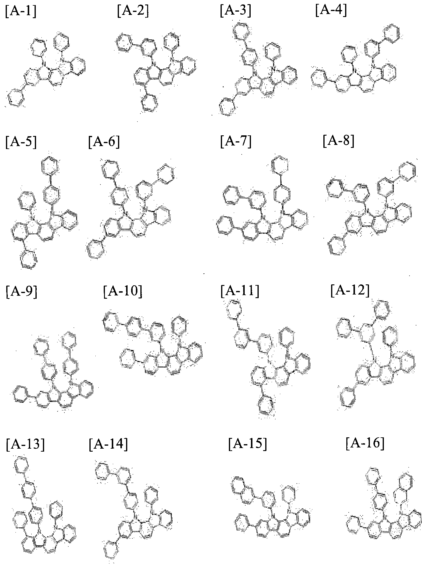
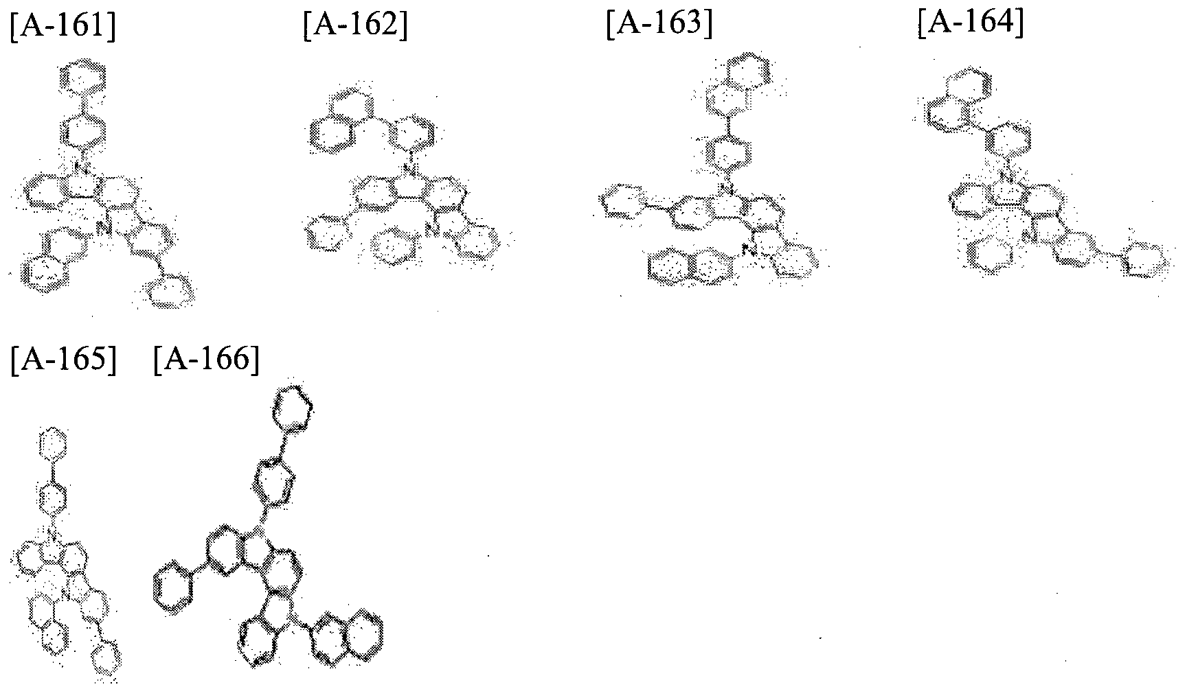
- the compounds for organic electroluminescent devices may be represented by, for example, the formulas listed in the following Group 1, but are not limited thereto.
- the compound for the second organic optoelectronic device may be represented by the following formula (3).
- Naeja Z 1 Z 3 are each independently N or CR b,
- At least two of Z 1 to Z 3 are N,
- R b and R 4 to R 6 are each independently hydrogen, deuterium, cyano, substituted or unsubstituted C 1 to C 10 alkyl group, substituted or unsubstituted C 6 to C 20 aryl group, or substituted or unsubstituted C 2 to C 30 A heterocyclic group,
- L 3 to L 5 are each independently a single bond or a substituted or unsubstituted C6 to C30 arylene group
- X < 1 > is O or S
- a 1 and A 2 are each independently a substituted or unsubstituted C6 to C20 aryl group or a substituted or unsubstituted C2 to C30 heterocyclic group.
- substitution in the above formula (3) means that at least one hydrogen is deuterium, C1 to C10 An alkyl group, or a C6 to C18 aryl group.
- the "substituted” means that at least one hydrogen is substituted with deuterium, a C1 to C4 alkyl group, or a C6 to C12 aryl group.
- at least one means that a hydrogen is substituted with a C1 to C4 alkyl group, a phenyl group, a biphenyl group, a naphthyl group, a terphenyl group, an anthracenyl, and, for example, means substituted with a phenyl group, a biphenyl group, a naphthyl group, or a terphenyl group do.
- all of Z 1 to Z 3 may be N.
- each of R 4 to R 6 may independently be hydrogen or a phenyl group.
- the compound for the second organic optoelectronic device may be represented by any one of the following formulas (3-a) to (3-d).
- Z 1 to Z 3 are each independently N or CR b ,
- At least two of Z 1 to Z 3 are N,
- R b and R 4 to R 6 are each independently hydrogen, deuterium, cyano, substituted or unsubstituted C 1 to C 10 alkyl group, substituted or unsubstituted C 6 to C 20 aryl group, or substituted or unsubstituted C 2 to C 30
- a heterocyclic group, L 3 to L 5 are each independently a single bond or a substituted or unsubstituted C6 to C30 arylene group,
- X < 1 > is O or S
- a 1 and A 2 are each independently a substituted or unsubstituted C6 to C20 aryl group or a substituted or unsubstituted C2 to C30 heterocyclic group.
- the Formula 3 of A 1 and A 2 are, each independently, a substituted or unsubstituted C6 to C30 aryl group, or a substituted or unsubstituted C2 to C30 heterocyclic group unsubstituted, ⁇ 1 and And any one of A < 2 > may be a substituted or unsubstituted C6 to C30 aryl group.
- a 1 is a substituted or unsubstituted C6 to C30 aryl group
- a 2 is a substituted or unsubstituted C6 to C30 aryl group or a substituted or unsubstituted C2 to C30 hetero Can be a ring.
- a < 1 > is a substituted or unsubstituted
- C6 to C20 aryl can group, wherein A 1 is, for example substituted or unsubstituted phenyl group, a substituted or unsubstituted biphenyl group, a substituted or unsubstituted terphenyl group, a substituted or unsubstituted quarter phenyl group, or a substituted or unsubstituted ring unsubstituted ring Naphthyl group, and the formula (3) may be represented by the following formula (3-1).
- Z 1 to Z 3 , R 4 to R 6 , L 3 to I ⁇ X 1 and A 2 are as defined above, and the definitions of R 7 and R 8 are the same as those of R 4 to R 6 Just as definition.
- a 1 in the above formula (3) may be selected from substituents listed in the following group ⁇ , for example.
- * is a connection point with L 4 .
- a 2 represents a substituted or unsubstituted phenyl group, a substituted or unsubstituted
- the compound for the second organic optoelectronic device may be represented by any one of the following formulas (3-1-1) to (3-1-3) according to the specific type of the ⁇ 2 .
- R 4 to the definition of R 8 is as defined above
- X 2 is the same as the definition of the aforementioned X 1
- 4 to ⁇ Z 6 is the same as defined in the above Z to Z 3
- the definitions of R c , R d and R e are the same as those of R 4 to R 8 described above.
- Ar 3 in the above formula (3-1-1) may be a substituted or unsubstituted C6 to C20 aryl group, and specifically, a substituted or unsubstituted phenyl group, a substituted or unsubstituted biphenyl group, a substituted or unsubstituted naphthyl group , A substituted or unsubstituted terphenyl group, or a substituted or unsubstituted quaterphenyl group, wherein the additional substituent may be deuterium, cyano group, phenyl group, or naphthyl group.
- R c and R d in formula (3-1-3) An optionally substituted or unsubstituted C6 to C20 aryl group, more specifically a phenyl group, a biphenyl group, a naphthyl group or a terphenyl group.
- a 2 in the above formula (3) may be selected from substituents listed in the following group m, for example.
- * is a connection point with L 5 .
- the compound for the second organic optoelectronic device can be represented by the formula 3-1-1 or the formula 3-1-2, wherein R 7 and R 8 are, for example, Ar 3 in the formula (3-1-1) may be, for example, a substituted or unsubstituted phenyl group, a substituted or unsubstituted biphenyl group, a substituted or unsubstituted biphenyl group, a substituted or unsubstituted biphenyl group, X 2 in the formula (3-1-2) may be 0 or S, and R c , R d and R e may each independently be hydrogen, deuterium, cyano or phenyl group.
- each of L 3 to L 5 independently represents a single bond, a substituted or unsubstituted phenylene group, a substituted or unsubstituted biphenylene group, a substituted or unsubstituted terphenylene group, Or an unsubstituted naphthylenylene group, and can be selected, for example, from the linking groups listed in the following Group IV.
- each of L 3 to L 5 may independently be a single bond or an unsubstituted phenylene group. More specifically, L < 3 > may be a single bond or an unsubstituted phenylene group, but a single bond is more preferable.
- the formula (3-1-1) may be represented by the following formula (3-1-la) or (3-1-lb)
- the formula (3-2) may be represented by the following formula (3-1-2a)
- Formula I 3- -3 has the following general formula 3- I -3a, -3b Formula 3- 1, 3- formula I -3c: Formula 3-1 -3d, formula 3-I-3e, and 3- formula I - 3f. ≪ / RTI >
- Formula 3-1 -la are each independently hydrogen -lb Formula 3-1, Formula I-2a-3,) and (3- I -3a) to (3- 1 -3f ⁇ l
- R 7 and R 8 may each independently be hydrogen, deuterium, a phenyl group, a biphenyl group, or a terphenyl group, more preferably all of R 4 to R 6 are hydrogen, R 7 and R 8 may each independently be hydrogen, a phenyl group, or a biphenyl group.
- the compound for a second organic optoelectronic device may be represented by, for example, the formula 3-1-1 or the formula 3- 1-2, Can be represented by the above-mentioned formulas (3-1-lb) and (3-1-2a).
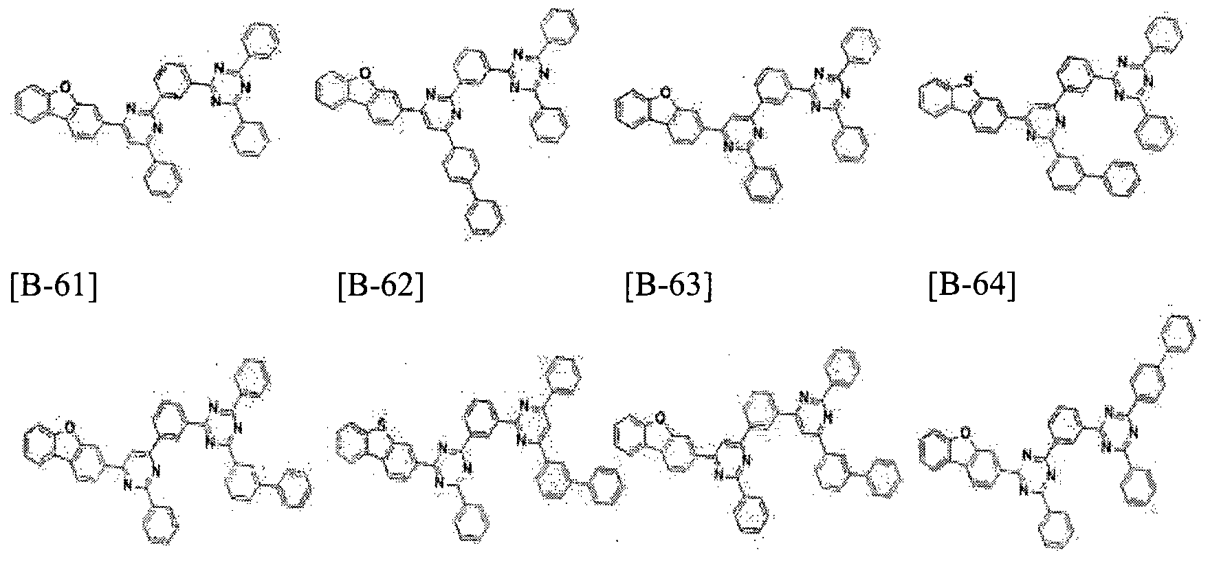
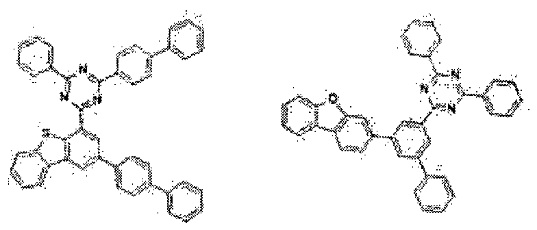
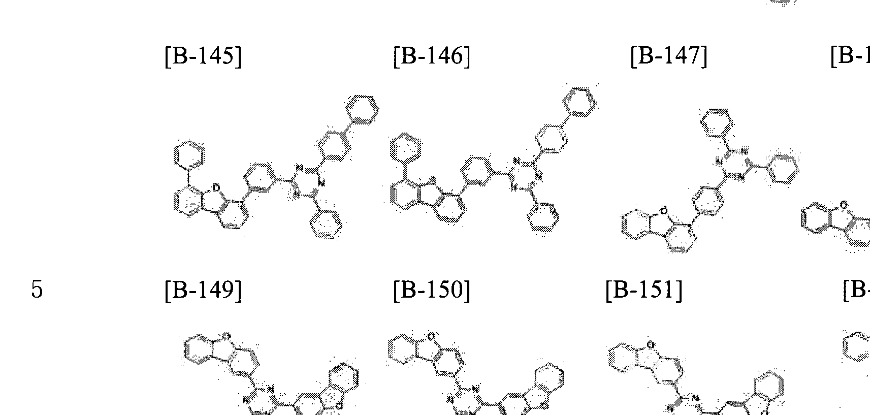
- the compound for the second organic optoelectronic device may be, for example, a compound listed in the following Group 2, but is not limited thereto.
- the compounds for the first organic optoelectronic device and the compound for the second organic optoelectronic device described above can be prepared in various compositions by various combinations.
- the compound for the organic electroluminescent device may be used in the light emitting layer together with the compound for the first organic optoelectronic device to improve the driving voltage, the luminous efficiency and the lifetime characteristics by increasing the charge mobility and increasing the stability.
- composition containing a first compound for an organic optoelectronic device and a second organic optoelectronic devices for the compound may further comprise a dopant.
- the splittable may be a red, green or blue scabbard, for example a red or green phosphorescent scabbard.
- a material such as a metal complex that emits light by multiple excitation, which excites the triplet state, may be used as the material of the platelet, which is a substance that emits light slightly.
- the dopant may be, for example, an inorganic, organic, or organic compound, and may include one or more species.
- Examples of the phosphorescent dopant include organic metal compounds including Ir, Pt, Os, Ti, Zr, Hf, Eu, Tb, Tm, Fe, Co, Ni, Ru, Rh, Pd, ,
- organic metal compounds including Ir, Pt, Os, Ti, Zr, Hf, Eu, Tb, Tm, Fe, Co, Ni, Ru, Rh, Pd, ,
- a compound represented by the following formula (Z) may be used, but is not limited thereto.
- M is a metal
- L and X are the same or different from each other and are ligands which complex with M.
- the L may be, for example, Ir, Pt, Os, Ti, Zr, Hf, Eu, Tb, Tm, Fe, Co, Ni, Ru, Rh, Pd, Lt; / RTI > More specifically, the phosphorescent dopant may be Ir, Pt, Os, Ti, Zr, Hf, Eu, Tb, Tm,
- the phosphorescent dopant may be an organometallic compound represented by the following Chemical Formula (401).
- M is at least one selected from the group consisting of Ir, Pt, Os, Ti, Zr, Hf, Eu, Tb and Tm
- 3 ⁇ 4 01 to X404 are independently nitrogen or carbon, and to each other;
- the A4 01 and A 402 rings may be, independently of one another, substituted or unsubstituted benzene, substituted or unsubstituted naphthalene, substituted or unsubstituted fluorene, substituted or unsubstituted spirofluorene, substituted or unsubstituted indene
- Substituted or unsubstituted thiophene substituted or unsubstituted furan, substituted or unsubstituted imidazole, substituted or unsubstituted pyrazole, substituted or unsubstituted thiazole ,
- Substituted or unsubstituted isothiazole substituted or unsubstituted oxazole, substituted or unsubstituted isooxazole, substituted or unsubstituted pyridine, substituted or unsub
- Substituted or unsubstituted benzothiophenes substituted or unsubstituted benzothiophenes, substituted or unsubstituted benzothiophenes, substituted or unsubstituted benzothiophenes, substituted or unsubstituted benzothiophenes, substituted or unsubstituted benzothiophenes, substituted or unsubstituted benzothiophenes, Substituted or unsubstituted benzoxazole, substituted or unsubstituted isobenzoxazole, substituted or unsubstituted triazole, substituted or unsubstituted oxadiazole, substituted or unsubstituted triazine, substituted or unsubstituted dibenzoazo Dibenzofliran and substituted or unsubstituted dibenzothiophene;
- substituted as used herein means that at least one hydrogen in the substituent
- ⁇ 401 may be any monovalent, divalent, or trivalent organic ligand.
- 1 ⁇ 01 may be a halogen ligand (e.g., C1, F), a diketone ligand (e.g.,
- carboxylic acid ligands such as picolinate, dimethyl-3-pyrazolecarboxylate, but are not limited to, carbon monoxide ligands, isonitrile ligands, cyano ligands, and phosphorus ligands (e.g., phosphine, phosphite).
- Q 40 l to Q 40 7, Q 4 11 to Q417 and Q 421 to Q427 are independently, hydrogen, C1 to C60 end kilgi, C2 to C60 alkenyl groups, C6 to C60 aryl group and a C2 to C60 heteroaryl group, Is selected.
- a 4 in Formula 401 has two or more substituents
- two or more substituents of A4 may be bonded to each other to form a saturated or unsaturated ring.
- a 401 402 is to have two or more substituents, bonded to each other at least two substituents of A 402 can form a saturated or unsaturated ring.
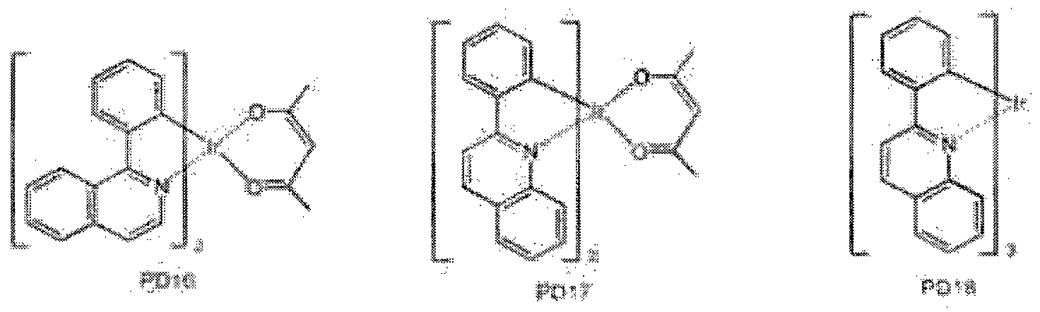
- the phosphorescent dopant may be a red or green phosphorescent dopant, and may be selected from but not limited to the following compounds PD1 to PD75:
- the charge mobility can be controlled by controlling the ratio of the compound for the first organic optoelectronic device to the compound for the second organic optoelectronic device.
- the combination ratio thereof may vary depending on the kind of the dopant used and the propensity of the dopant, and the compound for the first organic optoelectronic device and the compound for the second organic optoelectronic device For example, in a weight ratio of 1: 10 to 10: 1.
- the compound for a first organic optoelectronic device and The mixing weight ratio of the compound for the second organic optoelectronic device may be 5: 5.
- the bipolar characteristics can be more effectively realized by including them in the weight ratio range, thereby improving efficiency and lifetime at the same time.
- the composition may be formed by a dry film forming method such as chemical vapor deposition or a solution process.
- An organic optoelectronic device includes an anode and a cathode facing each other, and at least one organic layer positioned between the anode and the cathode, and the organic layer may include the composition for the organic optoelectronic device described above .
- the organic layer includes a light emitting layer, and the light emitting layer may include the composition for an organic optoelectronic device of the present invention.
- composition for the organic optoelectronic device may be included as a host of the light emitting layer, for example, a green host.
- the organic layer may include a light emitting layer, a hole injecting layer, a hole transporting layer, At least one auxiliary layer selected from an electron transport layer, an electron injection layer and a hole blocking layer, and the auxiliary layer may include the composition for the organic optoelectronic device.
- the organic optoelectronic device is not particularly limited as long as it is an element capable of converting electric energy and optical energy. Examples of the organic optoelectronic device include organic light emitting devices, organic solar cells, and organic photoconductor drums.
- an organic light emitting device 100 includes an anode 120 and a cathode 110 facing each other, and a cathode 110 disposed between the anode 120 and the cathode 110
- the anode 120 may be made of a conductor having a high work function to facilitate, for example, hole injection, and may be made of, for example, a metal, a metal oxide, and / or a conductive polymer.
- the anode 120 is made of a metal such as nickel, platinum, vanadium, chromium, copper, zinc, gold, or an alloy thereof; Zinc oxide, indium oxide, indium tin oxide (?
- Metal oxides such as indium zinc oxide (IZO); A combination of ZnO and Al or a metal and an oxide such as SnO2 and Sb; Poly (3-methylthiophene),
- conductive polymers such as poly (3,4- (ethylene-1,2-dioxy) thiophene Xpolyehtylenedioxythiophene: PEDT), polypyrrole and polyaniline.
- the cathode 110 may be made of a conductor having a low work function, for example, to facilitate electron injection, and may be made of, for example, a metal, a metal oxide, and / or a conductive polymer.
- the cathode 110 may be made of a metal such as magnesium, calcium, sodium, potassium, titanium, indium, yttrium, lithium, gadolinium, aluminum, silver, tin, lead, Layer structure materials such as LiF / Al, Li02 / Al, LiF / Ca, LiF / Al and BaF2 / Ca.
- the organic layer 105 includes the above-described compound for an organic optoelectronic device
- FIG. 2 is a cross-sectional view illustrating an organic light emitting device according to another embodiment.
- the organic light emitting diode 200 includes a light emitting layer 130
- the hole-assist layer 140 is formed between the anode 120 and the light- Hole injection and / or hole mobility can be further enhanced and electrons can be blocked.
- the hole-assist layer 140 may be, for example, a hole transport layer, a hole injection layer, and / or an electron blocking layer, and may include at least one layer.
- the organic light emitting devices 100 and 200 may be formed by forming an anode or a cathode on a substrate and then performing a dry deposition method such as evaporation, sputtering, plasma plating, and ion plating; Or a wet film formation method such as spin coating, dipping or flow coating, and then forming a cathode or anode on the organic layer.
- a dry deposition method such as evaporation, sputtering, plasma plating, and ion plating
- a wet film formation method such as spin coating, dipping or flow coating
- the organic light emitting device described above can be applied to an organic light emitting display.
- Compound B-2 was obtained in the same manner as in Synthesis Example a) by using 1.0 equivalent of 2,4-Bis ([1,1'-biphenyl] -4-yl) -6-chloro-1,3,5- / RTI >
- the glass substrate coated with ITO (Indium tin oxide) thin film with thickness of 1500 A was cleaned with distilled water ultrasonic wave. After the distilled water was washed, the substrate was ultrasonically cleaned with a solvent such as isopropyl alcohol, acetone, or methanol, dried and transferred to a plasma cleaner, the substrate was cleaned using oxygen plasma for 10 minutes, and then the substrate was transferred to a vacuum evaporator.
- Compound A was vacuum-deposited on the ITO substrate by using the ⁇ key transparent electrode as an anode to form a hole injection layer having a thickness of 700 A.
- Compound B was deposited on the injection layer to a thickness of 50 A, A to form a hole transport layer.
- Compound B-23 and Compound A-70 were simultaneously used as a host on the hole transport layer, doped with Ir (ppy) 3 as a dopant to 7 wt%, and vacuum-evaporated to form a light emitting layer having a thickness of 400A.
- the compound B-23 and the compound A-74 were used in a weight ratio of 5: 5, and in the case of the following examples,
- the organic light emitting device has a structure having five organic thin film layers. Specifically, the organic light emitting device has the following structure.
- the driving voltage was measured and the results were obtained.
- the current flowing through the unit device was measured using a current-voltmeter (Keithley 2400) while raising the voltage from 0 V to 10 V, and the measured current value was divided by the area to obtain the result.
- luminance was measured using a luminance meter (Minolta Cs-IOOOA) while increasing the voltage from 0 V to 10 V, and the result was obtained.
- the device using the polar Optronics lifetime measuring system for the manufacture of organic light emitting element of the initial luminance (cd / m 2) luminance for by and emit light at a 24000cd / m 2 measures the decrease in luminance with the passage of time by 90% compared to an initial brightness Is reduced to T90 life Respectively. (In the same ET host, the lifetime when using the compound C is expressed as a relative percentage, assuming 100%).
- the compound having a phenyl substituent at the side does not cause crystallization due to an increase in asymmetry and dipole moment compared to the symmetric compound a, If the side substituent is phenyl, HOMO electron cloud is not distributed and the hole does not move. However, if this substituent is too
Landscapes
- Chemical & Material Sciences (AREA)
- Engineering & Computer Science (AREA)
- Materials Engineering (AREA)
- Physics & Mathematics (AREA)
- Spectroscopy & Molecular Physics (AREA)
- Organic Chemistry (AREA)
- Optics & Photonics (AREA)
- Electroluminescent Light Sources (AREA)
- Plural Heterocyclic Compounds (AREA)
- Nitrogen Condensed Heterocyclic Rings (AREA)
Abstract
특정 화학식들의 조합으로 표현되는 제 1 유기 광전자 소자용 화합물; 및 또다른 특정 화학식으로 표현되는 제 2 유기 광전자 소자용 화합물을 포함하는 유기 광전자 소자용 조성물, 이를 적용한 유기 광전자 소자 및 표시 장치에 관한 것이다.
Description
【명세서】
【발명의 명칭]
유기 광전자 소자용 조성물, 유기 광전자 소자 및 표시 장치
【기술분야】
유기 광전자 소자용 조성물, 유기 광전자 소자 및 표시 장치에 관한 것이다.
【배경기술】
유기 광전자 소자 (organic optoelectronic diode)는 전기 에너지와 광 에너지를 상호 전환할 수 있는 소자이다.
유기 광전자 소자는 동작 원리에 따라 크게 두 가지로 나눌 수 있다. 하나는 광 에너지에 의해 형성된 엑시톤 (exciton)이 전자와 정공으로 분리되고 상기 전자와 정공이 각각 다른 전극으로 전달되면서 전기 에너지를 발생하는 광전 소자이고, 다른 하나는 전극에 전압 또는 전류를 공급하여 전기
에너지로부터 광 에너지를 발생하는 발광 소자이다.
유기 광전자 소자의 예로는 유기 광전 소자, 유기 발광소자, 유기 태양 전지 및 유기 감광체 드럼 (organic photo conductor drum) 등을 들 수 있다.
이 중, 유기 발광 소자 (organic light emitting diode, OLED)는 근래 평판 표시 장치 (flat panel display device)의 수요 증가에 따라 크게 주목받고 있다. 상기 유기 발광 소자는 유기 발광 재료에 전류를 가하여 전기 에너지를 빛으로 전환시키는 소자로서, 통상 양극 (anode)과 음극 (cathode) 사이에 유기 층이 삽입된 구조로 이루어져 있다. 여기서 유기 충은 발광층과 선택적으로 보조층을 포함할 수 있으며, 상기 보조층은 예컨대 유기발광소자의 효율과 안정성을 높이기 위한 정¾ 주입 층, 정공 수송 층, 전자차단 층, 전자 수송 층, 전자 주입 층 및 정공 차단 층에서 선택된 적어도 1층을 포함할 수 있다.
유기 발광 소자의 성능은 상기 유기 층의 특성에 의해 영향을 많이 받으며, 그 중에서도 상기 유기 층에 포함된 유기 재료에 의해 영향을 많이 받는다.
특히 상기 유기 발광 소자가 대형 평판 표시 장치에 적용되기 위해서는 정공 및 전자의 이동성을 높이는 동시에 전기화학적 안정성을 높일 수 있는 유기 재료의 개발이 필요하다.
【발명의 상세한 설명】
【기술적 과제】
일 구현예는 고효율 및 장수명 유기 광전자소자를 구현할 수 있는 유 광전자 소자용 조성물을 제공한다.
다른 구현예는 상기 조성물을 포함하는 유기 광전자 소자를 제공한다. 또 다른 구현예는 상기 유기 광전자 소자를 포함하는 표시 장치를 제공한다.
【기술적 해결방법】
일 구현예에 따르면, 하기 화학식 1 및 화학식 2의 조합으로 표현되는 유기 광전자 소자용 화합물; 및 하기 화학식 3으로표현되는 게 2 유기 광전자 소자용 화합물을 포함하는 유기 광전자 소자용 조성물을 제공한다.

상기 화학식 1 내지 화학식 3에서,
Ar1 및 Ar2는 각각 독립적으로 치환또는 비치환된 C6 내지 C30 아릴기이고,
R1 내지 R3은 각각 독립적으로, 수소, 중수소 또는 시아노기이고, 상기 화학식 1의 인접한 2개의 *은 상기 화학식 2의 *와 연결되고, 상기 화학식 1에서 상기 화학식 2의 *와 연결되지 않은 *은 각각 독립적으로 CRa이고,
Z1 내지 Z3은 각각 독립적으로 N또는 CRb이고,
Z1 내지 Z3 중 적어도 둘은 N이고,
Ra, Rb 및 R4 내지 R6은 각각 독립적으로, 수소, 중수소, 시아노기, 치환 또는 비치환된 C1 내지 C10 알킬기, 치환또는 비치환된 C6 내지 C20 아릴기, 또는 치환 또는 비치환된 C2 내지 C30 헤테로고리기이고,
L1 내지 L5는 각각 독립적으로 단일 결합, 또는 치환또는 비치환된 C6 내지 C30 아릴렌기이고,
X1은 O 또는 S이고,
A1 및 A2는 각각 독립적으로 치환또는 비치환된 C6 내지 C20 아릴기, 또는 치환또는 비치환된 C2 내지 C30 헤테로고리기이다.
다른 구현예에 따르면, 서로 마주하는 양극과 음극, 그리고 상기 양극과 상기 음극사이에 위치하는 적어도 한층의 유기층을 포함하고, 상기 유기층은 전술한 유기 광전자 소자용 조성물을 포함하는 유기 광전자 소자를 제공한다. 또 다른 구현예에 따르면 상기 유기 광전자 소자를 포함하는 표시 장치를 제공한다.
【유리한 효과】
고효율 장수명 유기 광전자 소자를 구현할 수 있다.
【도면의 간단한 설명】
도 1 및 도 2는 일 구현예에 따른 유기 발광 소자를 도시한 단면도이다. 【발명의 실시를 위한 최선의 형태】
이하, 본 발명의 구현예를 상세히 설명하기로 한다. 다만, 이는 예시로서 제시되는 것으로, 이에 의해 본 발명이 제한되지는 않으며 본 발명은 후술할 청구범위의 범주에 의해 정의될 뿐이다.
본 명세서에서 "치환''이란 별도의 정의가 없는 한, 치환기 또는 화합물 중의 적어도 하나의 수소가 중수소, 할로겐기, 히드록실기, 아미노기, 치환 또는 비치환된 C1 내지 C30 아민기, 니트로기, 치환또는 비치환된 C1 내지 C40 실릴기, C1 내지 C30 알킬기, C1 내지 C10 알킬실릴기, C6 내지 C30 아릴실릴기, C3 내지 C30 시클로알킬기, C3 내지 C30 헤테로시클로알킬기, C6 내지 C30 아릴기, C2 내지 C30 헤테로아릴기, C1 내지 C20 알콕시기, C1 내지 C10 트리플루오로알킬기, 시아노기, 또는 이들의 조합으로 치환된 것을 의미한다. 본'발명의 일 예에서 치환"은 치환기 또는 화합물 증의 적어도 하나의 수소가 중수소, C1 내지 C30 알킬기, C1 내지 C10 알킬실릴기, C6 내지 C30 아릴실릴기, C3 내지 C30 시클로알킬기, C3 내지 C30 헤테로시클로알킬기, C6 내지 C30 아릴기, C2 내지 C30 헤테로아릴기로 치환된 것을 의미한다. 또한, 본 발명의 구체적인 일 예에서, "치환"은 치환기 또는 화합물 증의 적어도 하나의 수소가 중수소, C1 내지 C20 알킬기, C6 내지 C30 아릴기, 또는 C2 내지 C30 헤테로아릴기로 치환된 것을 의미한다ᅳ 또한, 본 발명의 구체적인 일 예에서, "치환 "은 치환기 또는 화합물 중의 적어도 하나의 수소가 중수소, C1 내지 C5 알킬기, C6 내지 C18 아릴기, 디벤조퓨란일기, 또는 디벤조티오펜일기로 치환된
것을 의미한다. 또한, 본 발명의 구체적인 일 예에서, "치환"은 치환기 또는 화합물 중의 적어도 하나의 수소가 중수소, 메틸기, 에틸기, 프로판일기, 부틸기, 페닐기, 바이페닐기, 터페닐기, 나프틸기, 트리페닐기, 플루오레닐기,
디벤조퓨란일기 또는 디벤조티오펜일기로 치환된 것을 의미한다.
본 명세서에서 "헤테로"란 별도의 정의가 없는 한, 하나의 작용기 내에 N,
0, S, P 및 Si로 이루어진 군에서 선택되는 헤테로 원자를 1 내지 3개 함유하고, 나머지는 탄소인 것을 의미한다.
본 명세서에서 "알킬 (alkyl)기"이란 별도의 정의가 없는 한, 지방족 탄화수소기를 의미한다. 알킬기는 어떠한 이중결합이나 삼중결합을 포함하고 있지 않은 "포화 알킬 (saturated alkyl)기 "일 수 있다.
상기 알킬기는 C1 내지 C30인 알킬기일 수 있다. 보다 구체적으로 알킬기는 C1 내지 C20 알킬기 또는 C1 내지 C10 알킬기일 수도 있다. 예를 들어, C1 내지 C4 알킬기는 알킬쇄에 1 내지 4개의 탄소원자가 포함되는 것을 의미하며, 메틸, 에틸, 프로필, 이소-프로필 , η-부틸, 이소-부틸, sec-부틸 및 t-부틸로 이루어진 군에서 선택됨을 나타낸다ᅳ
상기 알킬기는 구체적인 예를 들어 메틸기, 에틸기, 프로필기,
이소프로필기, 부틸기, 이소부틸기, t-부틸기, 펜틸기, 핵실기, 시클로프로필기, 시클로부틸기, 시클로펜틸기, 시클로핵실기 등을 의미한다.
본 명세서에서 "아릴 (aryl)기"는 탄화수소 방향족 모이어티를 하나 이상 갖는 그룹을 총괄하는 개념으로서,
탄화수소 방향족 모이어티의 모든 원소가 P-오비탈을 가지면서, 이들 P-오비탈이 공액 (conjugation)을 형성하고 있는 형태, 예컨대 페닐기, 나프틸기 등을 포함하고,
2 이상의 탄화수소 방향족 모이어티들이 시그마 결합을 통하여 연결된 형태, 예컨대 바이페닐기, 터페닐기, 쿼터페닐기 등을 포함하며,
2 이상의 탄화수소 방향족 모이어티들이 직접 또는 간접적으로 융합된 비방향족 융합 고리도 포함할수 있다. 예컨대, 플루오레닐기 등을 들 수 있다. 아릴기는 모노시클릭, 폴리시클릭 또는 융합 고리 폴리시클릭 (즉, 탄소원자들의 인접한 쌍들을 나워 가지는 고리) 작용기를 포함한다.
본 명세서에서 "헤테로고리기 (heterocyclic group)"는 헤테로아릴기를 포함하는 상위 개념으로서, 아릴기, 시클로알킬기, 이들의 융합고리 또는 이들의
조합과 같은 고리 화합물 내에 탄소 (C) 대신 N, 0, S, P 및 Si로 이루어진 군에서 선택되는 헤테로 원자를 적어도 한 개를 함유하는 것을 의미한다. 상기
헤테로고리기가융합고리인 경우, 상기 헤테로고리기 전체 또는 각각의 고리마다 헤테로 원자를 한 개 이상 포함할 수 있다.
일 예로 "헤테로아릴 (heteroaryl)기 "는 아릴기 내에 N, 0, S, P 및 Si로 이루어진 군에서 선택되는 헤테로 원자를 적어도 한 개를 함유하는 것을
의미한다. 2 이상의 헤테로아릴기는 시그마 결합을 통하여 직접 연결되거나, 상기 헤테로아릴기가 2 이상의 고리를 포함할 경우, 2 이상의 고리들은 서로 융합될 수 있다. 상기 헤테로아릴기가 융합고리인 경우, 각각의 고리마다상기 헤테로 원자를 1 내지 3개 포함할 수 있다.
상기 헤테로고리기는 구체적인 예를 들어, 피리디닐기, 피리미디닐기, 、 피라지닐기, 피리다지닐기, 트리아지닐기, 퀴놀리닐기, 이소퀴놀리닐기,
퀴나졸리닐기 등을 포함할 수 있다.
보다구체적으로, 치환 또는 비치환된 C6 내지 C30 아릴기 및 /또는 치환 또는 비치환된 C2 내지 C30 헤테로고리기는, 치환또는 비치환된 페닐기, 치환 또는 비치환된 나프틸기, 치환또는 비치환된 안트라세닐기, 치환또는 비치환된 페난트레닐기, 치환또는 비치환된 나프타세닐기, 치환또는 비치환된 피레닐기, 치환또는 비치환된 바이페닐기, 치환 또는 비치환된 P-터페닐기, 치환또는 비치환된 m-터페닐기, 치환또는 비치환된 0-터페닐기, 치환또는 비치환된 크리세닐기, 치환또는 비치환된 트리페닐렌기, 치환또는 비치환된 페릴레닐기, 치환 또는 비치환된 플루오레닐기, 치환또는 비치환된 인데닐기, 치환 또는 비치환된 퓨라닐기, 치환 또는 비치환된 티오페닐기, 치환 또는 비치환된
피를릴기, 치환또는 비치환된 피라졸릴기, 치환 또는 비치환된 이미다졸일기, 치환또는 비치환된 트리아졸일기, 치환또는 비치환된 옥사졸일기, 치환또는 비치환된 티아졸일기, 치환 또는 비치환된 옥사디아졸일기, 치환또는 비치환된 티아디아졸일기, 치환또는 비치환된 피리딜기, 치환또는 비치환된 피리미디닐기, 치환또는 비치환된 피라지닐기, 치환 또는 비치환된 트리아지닐기, 치환또는 비치환된 벤조퓨라닐기, 치환또는 비치환된' 벤조티오페닐기, 치환또는 비치환된 벤즈이미다졸일기, 치환 또는 비치환된 인돌일기, 치환또는 비치환된 퀴놀리닐기, 치환또는 비치환된 이소퀴놀리닐기, 치환 또는 비치환된 퀴나졸리닐기, 치환 또는 비치환된 퀴녹살리닐기, 치환또는 비치환된 벤조퀴놀리닐기, 치환 또는
비치환된 벤조이소퀴놀리닐기, 치환또는 비치환된 벤조퀴나졸리닐기, 치환 또는 비치환된 나프티리디닐기, 치환또는 비치환된 벤즈옥사진일기, 치환또는 비치환된 벤즈티아진일기, 치환또는 비치환된 아크리디닐기, 치환또는 비치환된 페나진일기 , 치환 또는 비치환된 페노티아진일기 , 치환또는 비치환된
페녹사진일기, 치환 또는 비치환된 디벤조퓨란일기, 또는 치환또는 비치환된 디벤조티오펜일기, 또는 이들의 조합일 수 있으나, 이에 제한되지는 않는다.
본 명세서에서, 정공 특성이란, 전기장 (electric field)을 가했을 때 전자를 공여하여 정공을 형성할 수 있는 특성을 말하는 것으로 , HOMO 준위를 따라 전도 특성을 가져 양극에서 형성된 정공의 발광층으로의 주입, 발광층에서 형성된 정공의 양극으로의 이동 및 발광층에서의 이동을 용이하게 하는 특성을 의미한다. 또한 전자 특성이란, 전기장을 가했을 때 전자를 받을수 있는 특성을 말하는 것으로, LUMO 준위를 따라 전도 특성을 가져 음극에서 형성된 전자의 발광층으로꾀 주입, 발광층에서 형성된 전자의 음극으로의 이동 및 발광층에서의 이동을 용이하게 하는 특성을 의미한다. 이하 일 구현예에 따른 유기 광전자 소자용 조성물을 설명한다.
일 구현예에 따른 유기 광전자 소자용 조성물은 정공 특성이 상대적으로 강한 제 1 유기 광전자 소자용 화합물과 전자 특성이 상대적으로 강한 제 2 유기 광전자소자용 화합물을 동시에 포함함으로써, 전하 밸런스를 적절하게 맞추어 장수명 및 고효율의 유기 발광 소자를 제작할 수 있다.
상기 게 1 유기 광전자 소자용 화합물은 인돌로카바졸 코어의 어느 한 쪽 사이드 페닐 방향으로 페닐기가 치환된 비대칭 구조로서, 인돌로카바졸 코어의 사이드 페닐 방향이 비치환된 구조나 인돌로카바졸 코어의 양 쪽사이드 페닐 방향이 동일하게 치환된 대칭 구조 대비와 비교하여 비대칭성 및 dipole moment가 증가하여 결정화를 일으키자않으며 보다 균일한 막을 성막하여 수명에 좋은 영향을 준다.
특히, 인돌로카바졸 코어의 사이드 페닐 방향의 치환기가 2 이상의 페닐기가 연결되거나융합된 형태인구조 대비 본원과 같이 단일 페닐기인 구조의 경우, 본 구조의 경우 페닐 한 개의 치환기로서 HOMO 전자구름이 분포하지 않으며, hole 이 이동에 영향을 주지 않는다. 하지만 이 치환기가 bulky해지면 HOMO 전자구름이 분포해지며 hole 이동에 관여하며 inter-molecular
hole hopping거리가 늘어나게 되며 결국 원활한 hole 이동에 방해가됩니다. 이런 영향으로 구동이 밀리는 현상이 나타납니다.
상기 게 2 유기 광전자 소자용 화합물은 디벤조퓨란 (또는 디벤조티오펜)이 트리아진 또는 피리미딘 모이어티에 결합하는 구조를 포함함으로써 LUMO의 확장 및 ET 모이어티의 평면성 확장을 통하여 정공 및 전자의 주입 속도를 증가시킬 수 있다.
상기 게 1 유기 광전자 소자용 화합물은 하기 화학식 1 및 화학식 2의 조합으로 표현될 수 있다.

상기 화학식 1 및 화학식 2에서,
Ar1 및 Ar2는 각각독립적으로 치환 또는 비치환된 C6 내지 C30 아릴기이고,
R1 내지 R3은 각각 독립적으로, 수소, 중수소 또는 시아노기이고, 상기 화학식 1의 인접한 2개의 *은 상기 화학식 2의 *와 연결되고, 상기 화학식 1에서 상기 화학식 2의 *와 연결되지 않은 *은 각각 독립적으로 CRa이고,
L1 및 L2는 각각 독립적으로 단일 결합, 또는 치환 또는 비치환된 C6 내지 C30 아릴렌기이다.
상기 화학식 1 및 2의 "치환"이란, 적어도 하나의 수소가 중수소, C1 내지
C10 알킬기, 또는 C6 내지 C18 아릴기로 치환된 것을 의미한다.
본 발명의 일 예에서, 상기 "치환"이란, 적어도 하나의 수소가 중수소, C1 내지 C4 알킬기, 또는 C6 내지 C12 아릴기로 치환된 것을 의미한다. 구체적으로 적어도 하나의 수소가 C1 내지 C4 알킬기, 페닐기, 바이페닐기, 나프틸기, 터페닐기, 안트라세닐기로 치환된 것을 의미하며, 예컨대 페닐기, 바이페닐기, 나프틸기, 또는 터페닐기로 치환된 것을 의미한다.
상기 제 1 유기 광전자 소자용 화합물은 상기 화학식 1 및 화학식 2의 융합 위치에 따라 예컨대 하기 화학식 1A, 화학식 1B, 화학식 1C, 화학식 1D,
화학식 I E 및 화학식 IF 중 어느 하나로 표현될 수 있다.

상기 화학식 1A, 화학식 IB, 화학식 1C, 화학식 1D, 화학식 1E 및 화학식 1F 에서, ΑΓ', Α^ Ι 1 내지 1 및 L2는 전술한 바와 같고,
RAL 내지 RA4는 각각독립적으로, 수소, 중수소, 시아노기, 치환 또는 비치환된 C1 내지 C10 알킬기, 치환 또는 비치환된 C6 내지 C20 아릴기, 또는 치환 또는 비치환된 C2 내지 C30 헤테로고리기이다ᅳ
본 발명의 일 실시예에서, 상기 게 1 유기 광전자 소자용 화합물은 상기 화학식 1C로 표현될 수 있다.
한편, 상기 화학식 1C는 인돌로카바졸 코어에 치환된 사이드 페닐기의 구체적인 치환 위치에 따라 예컨대 하기 화학식 1C-1, 화학식 1 C-2, 화학식 1 C-3 및 화학식 1C-4 증 어느 하나로 표현될 수 있다.
[화학식 1C-1] [화학식 1C-2]
Ar1


상기 화학식 lC-l, 화학식 1C-2, 화학식 1C-3 및 화학식 1C-4에서, Ar1, Ar2, R1 내지 1 3, 1 ,1,1131 및 Ra2는 전술한 바와 같다.
본 발명의 구체적인 일 실시예에서, 상기 게 1 유기 광전자소자용 화합물은 상기 화학식 1C-2 또는 화학식 1C-3으로 표현될 수 있다.
본 발명의 더욱 구체적인 일 실시예에서, 상기 화학식 1 및 화학식 2의 Arl 및 Ar2는 각각 독립적으로 치환 또는 비치환된 페닐기, 치환또는 비치환된 바이페닐기, 치환또는 비치환된 터페닐기, 또는 치환또는 비치환된 나프틸기일 수 있고, 좋게는 상기 Ar1 및 Ar2는 각각 독립적으로 치환또는 비치환된 페닐기, 치환 또는 비치환된 바이페닐기, 치환 또는 비치환된 터페닐기일 수 있으며, 더욱 좋게는 예컨대 하기 그룹 I에 나열된 치환기에서 선택될 수 있다.

상기 그룹 I에서, *은 각각 L1 및 L2와의 연결 지점이다.
본 발명의 더욱 구체적인 일 실시예에서, 상기 화학식 1 및 화학식 2의 L1 및 L2는 각각 독립적으로 단일 결합, 치환또는 비치환된 페닐렌기, 또는 치환 또는 비치환된 바이페닐렌기일 수 있고, 좋게는 상가 L1 및 L2는 각각 독립적으로 단일 결합, 또는 치환또는 비치환된 페닐렌기일 수 있다. 이 때, 치환된
페닐렌기는 적어도 하나의 페닐기로 치환된 것일 수 있다.
본 발명의 더욱 구체적인 일 실시예에서, 상기 화학식 1 및 화학식 2의 R1 내지 R3은 각각 독립적으로, 수소 또는 시아노기일 수 있고, 좋게는 상기 R1 내지 R3은 모두 수소일 수 있다.
또한, 본 발명의 더욱 구체적인 일 실시예에서, 상기 화학식 1A 내지 화학식 ID의 Ral 내지 Ra4는 각각 독립적으로, 수소, 중수소, 시아노기, 치환 또는 비치환된 C1 내지 C10 알킬기, 또는 치환 또는 비치환된 C6 내지 C20 아릴기일 수 있고, 예컨대 수소, 중수소, 시아노기, 또는 치환 또는 비치환된 C6 내지 C20 아릴기일 수 있고, 좋게는 상기 Ral 내지 Ra4는 각각 독립적으로, 수소, 시아노기, 페닐기, 바이페닐기, 또는 나프틸기일 수 있으며 더욱 좋게는 상기 Ral 내지 Ra4는 모두 수소일 수 있다.
상기 게 1 유기 광전자 소자용 화합물은 예컨대 하기 그룹 1에 나열된 화학식으로 표현될 수 있으나, 이에 한정되는 것은 아니다.
[그룹 1]

V] LZ-Υ] V] [ξζ-γ] 5

IT
868ll0/8T0ZaM/X3d 9CS8Z.0/6T0Z OAV


Q

£1
868ΐΐΟ/8ΐΟΖΗΜ/Χ3<Ι 9CS8Z.0/6T0Z OAV

868ll0/8T0ZaM/X3d 9CS8Z.0/6T0Z OAV

LO o
【913〕 t£HVl- I /. I
:

-121] [A-122] [A-123] [A- 124]

 [091 -V] [8S1-V] [Lii-y]
c εi.
[L l-Y] [m-vl
[l7l7l-V] [m-γ]

[( -V] [6Π-Υ] [ ει-ν]
LI
68ΐΐΟ/8ΐΟΖΗΜ/Χ3<Ι 9CS8Z.0/6T0Z OAV
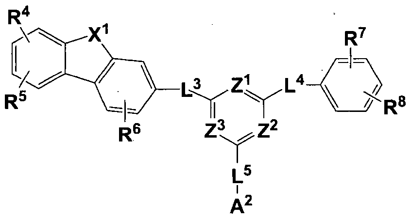
상기 제 2 유기 광전자 소자용 화합물은 하기 화학식 3으로 표현될 수 있다.

상기 화학식 3에서,
Z1 내자 Z3은 각각 독립적으로 N또는 CRb이고,
Z1 내지 Z3 중 적어도 둘은 N이고,
Rb 및 R4 내지 R6은 각각독립적으로, 수소, 중수소, 시아노기 , 치환또는 비치환된 C1 내지 C10 알킬기, 치환또는 비치환된 C6 내지 C20 아릴기, 또는 치환 또는 비치환된 C2 내지 C30 헤테로고리기이고,
L3 내지 L5는 각각 독립적으로 단일 결합, 또는 치환또는 비치환된 C6 내지 C30 아릴렌기이고,
X1은 0 또는 S이고,
A1 및 A2는 각각 독립적으로 치환또는 비치환된 C6 내지 C20 아릴기, 또는 치환 또는 비치환된 C2 내지 C30 헤테로고리기이다.
상기 화학식 3의 "치환"이란, 적어도 하나의 수소가 중수소, C1 내지 C10
알킬기, 또는 C6 내지 C18 아릴기로 치환된 것을 의미한다.
본 발명의 일 예에서, 상기 "치환"이란, 적어도 하나의 수소가중수소, C1 내지 C4 알킬기, 또는 C6 내지 C12 아릴기로 치환된 것을 의미한다. 구체적으로: 적어도 하나의 수소가 C1 내지 C4 알킬기, 페닐기, 바이페닐기, 나프틸기, 터페닐기, 안트라세닐기로 치환된 것을 의미하며, 예컨대 페닐기, 바이페닐기, 나프틸기, 또는 터페닐기로 치환된 것을 의미한다.
본 발명의 일 실시예에서, 상기 Z1 내지 Z3은 모두 N일 수 있다. 본 발명의 일 실시예에서, 상기 R4 내지 R6은 각각 독립적으로 수소 또는 페닐기일 수 있다.
예컨대, 상기 제 2 유기 광전자 소자용 화합물은 하기 화학식 3-a내지 화학식 3-d중 어느 하나로 표현될 수 있다.

상기 화학식 3-a내지 화학식 3-d에서,
Z1 내지 Z3은 각각 독립적으로 N또는 CRb이고,
Z1 내지 Z3 중 적어도 둘은 N이고,
Rb 및 R4 내지 R6은 각각 독립적으로, 수소, 중수소, 시아노기, 치환 또는 비치환된 C1 내지 C10 알킬기, 치환또는 비치환된 C6 내지 C20 아릴기, 또는 치환 또는 비치환된 C2 내지 C30 헤테로고리기이고,
L3 내지 L5는 각각 독립적으로 단일 결합, 또는 치환또는 비치환된 C6 내지 C30 아릴렌기이고,
X1은 0또는 S이고,
A1 및 A2는 각각 독립적으로 치환 또는 비치환된 C6 내지 C20 아릴기, 또는 치환 또는 비치환된 C2 내지 C30 헤테로고리기이다.
본 발명의 일 실시예에서, 상기 화학식 3의 A1 및 A2는 각각 독립적으로, 치환또는 비치환된 C6 내지 C30 아릴기, 또는 치환또는 비치환된 C2 내지 C30 헤테로고리기이고 , Α1 및 Α2 중 어느 하나는 치환또는 비치환된 C6 내지 C30 아릴기일 수 있다.
본 발명의 구체적인 일 실시예에서, 상기 A1은 치환 또는 비치환된 C6 내지 C30 아릴기이고, 상기 A2는 치환 또는 비치환된 C6 내지 C30 아릴기, 또는 치환또는 비치환된 C2 내지 C30 헤테로고리기일 수 있다.
본 발명의 더욱 구체적인 일 실시예에서, 상기 A1은 치환또는 비치환된
C6 내지 C20 아릴기일 수 있고, 상기 A1은 예컨대 치환또는 비치환된 페닐기, 치환또는 비치환된 바이페닐기, 치환또는 비치환된 터페닐기, 치환 또는 비치환된 쿼터페닐기, 또는 치환 또는 비치환된 나프틸기일 수 있으며, 상기 화학식 3은 하기 화학식 3- I로 표현될 수 있다.

상기 화학식 3- 1에서 , Ζ1 내지 Z3, R4 내지 R6, L3 내지 ΙΛ Χ1 및 Α2는 전술한 바와 같고 , R7 및 R8의 정의는 전술한 R4 내지 R6의 정의와 같다.
상기 화학식 3의 A1은 예컨대 하기 그룹 Π에 나열된 치환기에서 선택될 수 있다.

상기 그룹 Π에서, *은 L4와의 연결 지점이다.
한편, 상기 Α2는 치환 또는 비치환된 페닐기, 치환또는 비치환된
바이페닐기, 치환 또는 비치환된 나프틸기, 치환 또는 비치환된 터페닐기, 치환 또는 비치환된 쿼터페닐기, 치환 또는 비치환된 디벤조퓨란일기, 치환 또는 비치환된 디벤조티오펜일기, 치환또는 비치환된 피리미디닐기, 또는 치환 또는 비치환된 트리아지닐기일 수 있고,
특히, 상기 Α2의 구체적인 종류에 따라상기 제 2 유기 광전자 소자용 화합물은 하기 화학식 3-1-1 내지 화학식 3-1-3 중 어느 하나로 표현될 수 있다.

상기 화학식 3-1-1 내지 화학식 3-1-3에서, 3, 내지 Z3,R4 내지 R8의 정의는 전술한 바와 같고, X2는 전술한 X1의 정의와 같고 ,Ζ4 내지 Ζ6은 전술한 Ζ 내지 Ζ3의 정의와 같으며, Rc,Rd 및 Re의 정의는 전술한 R4 내지 R8의 정의와 같다.
또한, 상기 화학식 3- 1-1의 Ar3은 치환 또는 비치환된 C6 내지 C20 아릴기일 수 있고, 구체적으로 치환또는 비치환된 페닐기, 치환또는 비치환된 바이페닐기, 치환또는 비치환된 나프틸기, 치환 또는 비치환된 터페닐기, 또는 치환또는 비치환된 쿼터페닐기일 수 있으며, 이 때 추가 치환기는 중수소, 시아노기, 페닐기, 또는 나프틸기일 수 있다.
본 발명의 구체적인 일 실시예에서, 화학식 3-1-3 중 Rc 및 Rd은 각각
독립적으로 치환또는 비치환된 C6 내지 C20 아릴기일 수 있으며, 보다 구체적으로 페닐기, 바이페닐기, 나프틸기 또는 터페닐기일 수 있다.
상기 화학식 3의 A2는 예컨대 하기 그룹 m에 나열된 치환기에서 선택될 f 있다.

상기 그룹 m에서, *은 L5와의 연결 지점이다.
본 발명의 가장 구체적인 일 실시예에서, 상기 제 2 유기 광전자소자용 화합물은 상기 화학식 3- I -1 또는 화학식 3- I -2로 표현될 수 있고, 이 때 R7 및 R8은 예컨대 각각 독립적으로 수소, 중수소, 시아노기, 페닐기,또는 바이페닐기일 수 있고, 상기 화학식 3- 1 -1의 Ar3은 예컨대 치환또는 비치환된 페닐기, 치환 또는 비치환된 바이페닐기, 또는 치환 또는 비치환된 터페닐기일 수 있고, 상기 화학식 3- 1 -2의 X2는 0또는 S이며, Rc, Rd 및 Re는 각각 독립적으로, 수소, 중수소, 시아노기 또는 페닐기일 수 있다.
본 발명의 가장 구체적인 일 실시예에서, 상기 L3 내지 L5는 각각 독립적으로 단일 결합이거나 치환또는 비치환돤페닐렌기, 치환 또는 비치환된 바이페닐렌기, 치환 또는 비치환된 터페닐렌기, 또는 치환 또는 비치환된 나프틸레닐렌기일 수 있고, 예컨대 하기 그룹 IV에 나열된 연결기에서 선택될 수 있다.

상기 그룹 IV에서, *은 연결 지점이다.
더욱 구체적인 일 실시예에서, 상기 L3 내지 L5는 각각 독립적으로 단일 결합이거나 비치환된 페닐렌기일 수 있다. 보다 구체적으로 L3은 단일 결합이거나 비치환된 페닐렌기일 수 있으나, 단일 결합이 보다 바람직하다. 또한, 본 발명의 더욱 구체적인 일 실시예에서, 상기 화학식 3- 1-1은 하기 화학식 3-1 -la또는 화학식 3-1 -lb로 표현될 수 있고,

상기 화학식 3- 1-2는 하기 화학식 3-1 -2a로 표현될 수 있으며,
[화학식 3- I -2a]

상기 화학식 3- I -3은 하기 화학식 3- I -3a, 화학식 3- 1 -3b, 화학식 3- I -3c: 화학식 3-1 -3d,화학식 3-I-3e, 및 화학식 3- I -3f 중 어느 하나로 표현될 수 있다.

상기 화학식 3- I -la, 화학식 3- I -lb, 화학식 3- I -2a, 및 화학식 3- I -3a 내지 화학식 3- I -3f에서,
 내지 L5,Rc,Rd,Re 및 R4 내지 R8의 정의는 전술한 바와 같다.
예컨대, 상기 화학식 3-1 -la, 화학식 3-1 -lb, 화학식 3-I-2a, 및 화학식 3- I -3a내지 화학식 3- 1 -3f≤l R4 내지 R6은 각각 독립적으로 수소, 중수소, 페닐기, 또는 바이페닐기일 수 있고, R7 및 R8은 각각 독립적으로 수소, 중수소, 페닐기, 바이페닐기, 또는 터페닐기일 수 있고, 더욱 좋게는 R4 내지 R6은 모두 수소이고, R7 및 R8은 각각 독립적으로 수소, 페닐기, 또는 바이페닐기일 수 있다. 또한, 상기 화학식 3의 Z1 내지 Z3으로 이루어진 함질소 6각환은
피리미디닐기, 또는 트리아지닐기일 수 있으며, 더욱 좋게는 트리아지닐기일 수 있다.
본 발명의 구체적인 일 실시예에서, 상기 제 2 유기 광전자 소자용 화합물은 예컨대 상기 화학식 3-1-1 또는 화학식 3- 1-2로 표현될 수 있고, 더욱 좋게는 상기 화학식 3-1 -la, 상기 화학식 3-1 -lb 및 상기 화학식 3-1 -2a로 표현될 수 있다.
상기 제 2 유기 광전자 소자용 화합물은 예컨대 하기 그룹 2에 나열된 화합물일 수 있으나, 이에 한정되는 것은 아니다.
[그룹 2]

26


[B-65] [B-66] [B-67] [B-68]
 B-69] [B-70]

B-85] B-86]

[ [B-91] [B-92]

//:/ O 868Π08Ϊ02Μ129ε-ο6ϊοζAV


[£9i-a] [291-9] [191-a] -8] [6si-a] [8S1-H] [z자 a]
[9si-el [ssi-e] [ ι [£si-el

[isi-e] [osi-e]

868ll0/8T0ZaM/X3d 9CS8Z.0/6T0Z OAV
/ O S806Ϊ0AV

o

전술한 제 1 유기 광전자 소자용 화합물과 제 2 유기 광전자 소자용 화합물은 다양한조합에 의해 다양한조성물을 준비할 수 있다.
상기 게 2 유기 광전자 소자용 화합물은 상기 제 1 유기 광전자 소자용 화합물과 함께 발광층에 사용되어 전하의 이동성을 높이고 안정성을 높임으로써 구동전압, 발광 효율 및 수명 특성을 개선시킬 수 있다.
상기 '제 1 유기 광전자 소자용 화합물과 제 2 유기 광전자 소자용 화합물을 포함하는 조성물은 도판트를 더 포함할 수 있다.
상기 도편트는 적색, 녹색 또는 청색의 도편트일 수 있으며, 예컨대 적색 또는 녹색의 인광 도편트일 수 있다.
상기 도편트는 미량 흔합되어 발광을 일으키는 물질로, 일반적으로 삼중항 상태 이상으로 여기시키는 다중항 여기 (multiple excitation)에 의해 발광하는 금속 착체 (metal complex)와 같은 물질이 사용될 수 있다. 상기 도펀트는 예컨대 무기, 유기, 유무기 화합물일 수 있으며 , 1종 또는 2종 이상 포함될 수 있다.
상기 인광 도편트의 예로는 Ir, Pt, Os, Ti, Zr, Hf, Eu, Tb, Tm, Fe, Co, Ni, Ru, Rh, Pd또는 이들의 조합을 포함하는 유기 금속화합물을 들 수 있고, 예컨대 하기 화학식 Z로 표현되는 화합물을 사용할 수 있으나, 이에 한정되는 것은 아니다.
[화학식 Z]
L2MX
상기 화학식 Z에서 , Μ은 금속이고, L 및 X는 서로 같거나 다르며 Μ과 착화합물을 형성하는 리간드이다.
상기 Μ은 예컨대 Ir, Pt, Os, Ti, Zr, Hf, Eu, Tb, Tm, Fe, Co, Ni, Ru, Rh, Pd또는 이들의 조합일 수 있고, 상기 L 및 X는 예컨대 바이덴테이트 리간드일 수 있다. 더욱 구체적으로, 상기 인광 도편트는 Ir, Pt, Os, Ti, Zr, Hf, Eu, Tb, Tm, Fe, Co,
Ni, Ru, Rh, Pd또는 이들의 조합 중 하나를 포함하는 유기 금속화합물일 수 있고, 구체적인 일 실시예에서, 상기 인광 도편트는 하기 화학식 401로 표시되는 유기금속화합물일 수 있다.

상기 화학식 401 중 , M은 Ir, Pt, Os, Ti, Zr, Hf, Eu, Tb 및 Tm중에서
선택되고; ¾01 내지 X404는 서로 독립적으로, 질소 또는 탄소이고; A401 및 A402 고리는 서로 독립적으로, 치환 또는 비치환된 벤젠, 치환 또는 비치환된 나프탈렌, 치환 또는 비치환된 플루오렌, 치환또는 비치환된 스파이로 -플루오렌, 치환 또는 비치환된 인덴, 치환또는 비치환된 피를, 치환또는 비치환된 티오펜, 치환 또는 비치환된 퓨란 (foran), 치환또는 비치환된 이미다졸, 치환또는 비치환된 피라졸, 치환 또는 비치환된 티아졸, 치환또는 비치환된 이소티아졸, 치환 또는 비치환된 옥사졸, 치환 또는 비치환된 이속사졸 (isooxazole), 치환또는 비치환된 피리딘, 치환또는 비치환된 피라진, 치환또는 비치환된 피리미딘, 치환 또는 비치환된 피리다진, 치환 또는 비치환된 퀴놀린, 치환 또는 비치환된 이소퀴놀린, 치환 또는 비치환된 벤조퀴놀린, 치환또는 비치환된 퀴녹살린, 치환또는 비치환된
퀴나졸린, 치환 또는 비치환 ^ 카바졸, 치환또는 비치환된 벤조이미다졸, 치환 또는 비치환된 벤조퓨란 (benzoftiran), 치환 또는 비치환된 벤조티오펜, 치환 또는 비치환된 이소벤조티오펜, 치환또는 비치환된 벤조옥사졸, 치환 또는 비치환된 이소밴조옥사졸, 치환또는 비치환된 트리아졸, 치환또는 비치환된 옥사디아졸, 치환또는 비치환된 트리아진, 치환또는 비치환돤디벤조퓨란 (dibenzofliran) 및 치환또는 비치환된 디벤조티오펜 중에서 선택되고; 여기서 "치환 "이란 치환기 또는 화합물 중의 적어도 하나의 수소가 중수소, 할로겐기, 히드록실기, 시아노기, 아미노기, 치환 또는 비치환된 C1 내지 C30 아민기, 니트로기, 치환또는
비치환된 C1 내지 C40 실릴기, C1 내지 C30 알킬기, C1 내지 C10 알킬실릴기, C6 내지 C30 아릴실릴기, C3 내지 C30 시클로알킬기, C3 내지 C30
헤테로시클로알킬기, C6 내지 C30 아릴기, C2 내지 C30 헤테로고리기, C1 내지 C20 알콕시기, C1 내지 C10트리플루오로알킬기, 또는 이들의 조합으로 치환된 것을 의미하고; 1 01은 유기 리간드이고; xcl은 1, 2 또는 3이고; xc2는 0, 1, 2 또는 3이다.
상기 !^401은 임의의 1가, 2가 또는 3가의 유기 리간드일 수 있다. 예를 들어, 1^01은 할로겐 리간드 (예를 들면, C1, F), 디케톤 리간드 (예를 들면,
아세틸아세토네이트, 1,3-디페닐 -1,3-프로판디오네이트,
2,2,6,6-테트라메틸 -3,5-헵탄디오네이트, 핵사플루오로아세토네이트), 카르복실산 리간드 (예를 들면, 피콜리네이트, 디메틸 -3-피라졸카르복실레미트, 벤조에이트), 카본 모노옥사이드 리간드, 이소니트릴 리간드, 시아노 리간드 및 포스포러스 리간드 (예를 들면, 포스핀 (phosphine), 포스파이트 (phosphite)) 중 선택될 수 있으나, 이에 한정되는 것은 아니다.
상기 Q40l 내지 Q407, Q411 내지 Q417 및 Q421 내지 Q427은 독립적으로, 수소, C1 내지 C60말킬기, C2 내지 C60 알케닐기, C6 내지 C60 아릴기 및 C2 내지 C60 헤테로아릴기 중에서 선택된다.
상기 화학식 401 중 A4이가 2 이상의 치환기를 가질 경우, A4이의 2 이상의 치환기를 서로 결합하여 포화또는 불포화 고리를 형성할 수 있다.
상기 화학식 401 중 A402가 2 이상의 치환기를 가질 경우 , A402의 2 이상의 치환기를 서로 결합하여 포화 또는 불포화 고리를 형성할 수 있다.
상기 화학식 401 중 xcl이 2 이상일 경우, 화학식 401 중 복수의 리간드는 서로 동일하거나상이할 수 있다. 상기 화학식 401 중 xcl이 2 이상일 경우, A401 및 A402는 각각 이웃하는 다른 리간드의 A401 및 A402와 각각 직접 (directly) 또는 연결기 (예를 들면, C1 내지 C5 알킬렌기, -N(R')- (여기서, R'은 C1 내지 C10 알킬기 또는 C6 내지 C20 아릴기임) 또는 -C(=0)-)를 사이에 두고 연결될 수 있다.
예컨대, 상기 인광 도편트는 적색 또는 녹색의 인광 도펀트일 수 있으며, 하기 화합물 PD1 내지 PD75 중에서 선택될 수 있으나, 이에 한정되는 것은 아니다:




6t
868ll0/8T0ZaM/X3d 9CS8Z.0/6T0Z OAV


em*
또한 상기 계 2 유기 광전자 소자용 화합물과 상기 제 1 유기 광전자 소자용 화합물의 비율을 조절함으로써 전하의 이동성을 조절할 수 있다. 본 발명의 조성물이 호스트로 사용되는 경우 이들의 조합 비율은사용된 도판트의 종류나 도판트의 성향에 따라 달라질 수 있으며, 상기 제 1 유기 광전자 소자용 화합물과상기 제 2 유기 광전자소자용 화합물은 예컨대 1 :10내지 10:1의 중량비로 포함될 수 있다. 구체적으로 2:8 내지 8:2, 9:1 내지 5:5, 8:2 내지 5:5, 7:3 내지 5:5일 수 있고, 가장 구체적인 예로서, 제 1 유기 광전자 소자용 화합물과 제 2 유기 광전자 소자용 화합물의 혼합 중량비는 5:5 일 수 있다.
상기 중량비 범위로 포함됨으로써 바이폴라 특성이 더욱 효과적으로 구현되어 효율과수명을 동시에 개선할 수 있다.
상기 조성물은 화학기상증착과 같은 건식 성막법 또는 용액 공정으로 형성될 수 있다.
이하 전술한 유기 광전자 소자용 조성물을 적용한 유기 광전자소자를 설명한다.
다른 구현예에 따른 유기 광전자 소자는 서로 마주하는 양극과 음극, 그리고 상기 양극과 상기 음극사이에 위치하는 적어도 한 층의 유기층을 포함하고, 상기 유기층은 전술한 유기 광전자 소자용 조성물을 포함할 수 있다. 일 예로 상기 유기층은 발광층을 포함하고, 상기 발광층은 본 발명의 유기 광전자 소자용 조성물을 포함할수 있다.
구체적으로, 상기 유기 광전자 소자용 조성물은 상기 발광층의 호스트, 예컨대 그린 호스트로서 포함될 수 있다.
또한, 상기 유기층은 발광층, 및 정공주입층, 정공수송층, 전자차단층,
전자수송층, 전자주입층 및 정공차단층에서 선택된 적어도 하나의 보조층을 포함하고, 상기 보조층은 상기 유기 광전자 소자용 조성물을 포함할 수 있다. 상기 유기 광전자 소자는 전기 에너지와 광 에너지를 상호 전환할 수 있는 소자이면 특별히 한정되지 않으며, 예컨대 유기 광전 소자, 유기 발광소자, 유기 태양 전지 및 유기 감광체 드럼 등을 들 수 있다.
여기서는 유기 광전자 소자의 일 예인 유기 발광소자를 도면을 참고하여 설명한다.
도 1 및 도 2는 일 구현예에 따른 유기 발광소자를 보여주는 단면도이다. 도 1을 참고하면, 일 구현예에 따른 유기 발광 소자 (100)는 서로 마주하는 양극 (120)과 음극 (110), 그리고 양극 (120)과 음극 (110)사이에 위치하는
유기층 (105)을 포함한다.
양극 (120)은 예컨대 정공 주입이 원활하도록 일 함수가높은 도전체로 만들어질 수 있으며, 예컨대 금속, 금속 산화물 및 /또는 도전성 고분자로 만들어질 수 있다. 양극 (120)은 예컨대 니켈, 백금, 바나듐, 크롬, 구리, 아연, 금과 같은 금속 또는 이들의 합금; 아연산화물, 인듐산화물, 인듐주석산화물 (ΠΌ),
인듐아연산화물 (IZO)과 같은 금속 산화물; ZnO와 A1 또는 Sn02와 Sb와 같은 금속과 산화물의 조합; 폴리 (3-메틸티오펜),
폴리 (3,4- (에틸렌 -1,2-디옥시)티오펜 Xpolyehtylenedioxythiophene: PEDT), 폴리피를 및 폴리아닐린과 같은 도전성 고분자 등을 들 수 있으나, 이에 한정되는 것은 아니다.
음극 (110)은 예컨대 전자주입이 원활하도록 일 함수가낮은 도전체로 만들어질 수 있으며, 예컨대 금속, 금속 산화물 및 /또는 도전성 고분자로 만들어질 수 있다. 음극 (110)은 예컨대 마그네슘, 칼슘, 나트륨, 칼륨, 타이타늄, 인듐, 이트륨, 리튬, 가돌리늄, 알루미늄, 은, 주석, 납, 세슴, 바륨 등과 같은 금속 또는 이들의 합금; LiF/Al, Li02/Al, LiF/Ca, LiF/Al 및 BaF2/Ca과 같은 다층 구조 물질을 들 수 있으나, 이에 한정되는 것은 아니다.
유기층 (105)은 전술한 유기 광전자 소자용 화합물을 포함하는
발광층 (130)을 포함한다.
도 2는 다른 구현예에 따른 유기 발광 소자를 보여주는 단면도이다.
도 2를 참고하면, 유기 발광 소자 (200)는 발광층 (130) 외에 정공
보조층 (140)을 더 포함한다. 정공 보조층 (140)은 양극 (120)과 발광층 (130)사이의
정공 주입 및 /또는 정공 이동성을 더욱 높이고 전자를 차단할 수 있다. 정공 보조층 (140)은 예컨대 정공 수송층, 정공 주입층 및 /또는 전자 차단층일 수 있으며, 적어도 1층을포함할 수 있다.
도 1 또는 도 2의 유기층 (105)은 도시하지는 않았지만, 전자주입층, 전자수송층, 전자수송보조층, 정공수송층, 정공수송보조층, 정공주입층 또는 이들의 조합층을 추가로 더 포함할 수 있다. 본 발명의 유기 광전자 소자용 화합물은 이들 유기층에 포함될 수 있다. 유기 발광 소자 (100, 200)는 기판 위에 양극 또는 음극을 형성한후, 진공증착법 (evaporation), 스퍼터링 (sputtering), 플라즈마 도금 및 이온도금과 같은 건식성막법; 또는 스핀코팅 (spin coating), 침지법 (dipping), 유동코팅법 (flow coating)과 같은 습식성막법 등으로 유기층을 형성한후, 그 위에 음극 또는 양극을 형성하여 제조할 수 있다.
전술한유기 발광 소자는 유기 발광 표시 장치에 적용될 수 있다.
【발명의 실시를 위한 형태】
이하에서는 본 발명의 구체적인 실시예들을 제시한다. 다만, 하기에 기재된 실시예들은 본 발명을 구체적으로 예시하거나 설명하기 위한 것에 불과하며, 이로서 본 발명이 제한되어서는 아니된다.
이하, 실시예 및 합성예에서 사용된 출발물질 및 반웅물질은 특별한 언급이 없는 한, Sigma-Aldrich社 또는 TCI .社에서 구입하였거나, 공지된 방법을 통해 합성하였다.
(유기 광전자소자용화합물의 제조)
본 발명의 화합물의 보다 구체적인 예로서 제시된 화합물을 하기 단계를 통해 합성하였다. ·
(제 1유기 광전자소자용화합물)
<반웅식 1>


1000ml플라스크에 중간체 L-1 30.0g (121.90mmol), 보론에스터 46.43g
(182.85mmol), 포타슘아세테이트 29.91g (304.75mmol), Pd(dppf)Cl2 4.98g (6.10mmol)을 를루엔 400mL에 넣어준 후, 질소 기류 하에서 12시간 동안 가열하여 환류하였다. 이로부터 수득한 흔합물을 메탄올 1500mL에 가하여 결정화된 고형분을 여과한 후, 다이클로로메탄 녹여 실리카겔 /셀라이트로 여과하고, 유기 용매를 적당량 제거한후, 핵산로 재결정하여 화합물 L-2 (27.1g, 76%의 수율)을 수득하였다.
합성예 2 : 중간체 L-3 의 합성
500mL플라스크에 중간체 L-2 20.0g (68.22mmol), 2,4-Dichloronitrobenzene 14.41g (75.04mmol), 탄산칼륨 23.57g (170.55mmol), Pd(PPh3)4
(Tetrakis(triphenylphosphine) palladium(O)) 3.94g (3.41mmol)을 테트라하이드로퓨란 170mL, 물 80mL에 넣어준 후, 질소 기류 하에서 10시간동안 가열하여
환류하였다. 이로부터 수득한 흔합물을 메탄을 500mL에 가하여 결정화된 고형분을 여과한 후, 다이클로로메탄에 녹여 실리카겔 /셀라이트로 여과하고, 유기 용매를 적당량 제거한후, 핵산으로 재결정하여 화합물 L-3(15.30g, 69%의 수율)을 수득하였다.
합성예 3: 중간체 L-4 의 합성
500mL플라스크에 중간체 L-3 15g(46.48mmol), 3-브로모바이페닐 11.38g
(48.80mmol) 소듐 t-부톡사이드 11.17g(116.19mmol), Pd(dba)2 l.34g(2.32mmol), 트리 t-부틸포스핀 3.40mL(50% in를루엔) 를루엔 150ml를 넣고 질소 기류 하에서 130도 가열 교반 한다. 15시간 경과 후 반웅을 종료한다 이로부터 수득한 흔합물을 메탄올 700mL에 가하여 결정화된 고형분을 여과한후, 를루엔에 녹여 실리카겔 /셀라이트로 여과하고, 유기 용매를 적당량 제거한 후, 메탄올로 재결정하여 중간체 L-4 ( .3g 78%의 수율)을 수득하였다.
합성예 4: 중간체 L-5 의 합성
250mL플라스크에 중간체 L-5 30g(63.17mmol)과 용매 트리페닐포스핀 41.42g(157.91mmol)을 넣고 용매 다이클로로벤젠 150ml 질소 기류 하에서 160°C 가열 교반 한다. 4시간 경과 후 반웅을 종료한다. 다이클로로벤젠을 증류기를 통하여 응축하여 컬럼 정제를 (다이클로로메탄 2 : 핵산 8) 통하여 중간체
L-5(17.1g 61%의 수율)을 수득하였다.
합성예 5: 중간체 L-6의 합성
250mL플라스크에 중간체 L-5 15g(33.86mmol), 4-브로모바이페닐 8.29g (35.56mmol) 소듐 t-부특사이드 8.14g(84.66mmol), Pd(dba)2 0.97g(1.69mmol), 트리 t-부틸포스핀 2.48mL(50% in를루엔) 를루엔 110ml를 넣고 질소 기류 하에서 130도 가열 교반 한다. 15시간 경과 후 반응을 종료한다. 이로부터 수득한 흔합물을 메탄올 500mL에 가하여 결정화된 고형분을 여과한 후, 를루엔에 녹여 실리카겔 /샐라이트로 여과하고, 유기 용매를 적당량 제거한후, 핵산으로 재결정하여 중간체 L-6 (12.7g 79%의 수율)을 수득하였다.
합성예 6 : 화학식 A-74의 합성
500mL플라스크에 중간체 L-6 20.0g (33.61mmol), Phenyl boronic acid 4.51g (36.97mmol), 탄산칼륨 11.61g (84.02mmol), Pd(PPh3)4 (Tetrakis(triphenylphosphine) palladium(O)) 1.94g (1.68mmol)을 테트라하이드로퓨란 170mL, 물 80mL에 넣어준 후 질소 기류 하에서 10시간 동안 가열하여 환류하였다. 이로부터 수득한흔합물을 메탄^ 500mL에 가하여 결정화된 고형분을 여과한후, 를루엔을 가열하여 녹여 실리카겔 /셀라이트로 여과하고, 유기 용매를 적당량 제거한후, 핵산으로 재결정하여 화합물 A-74(16.50g, 77%의 수율)을 수득하였다. 위와 같은 방식으로 화학식 A-70, A-72, A-166, A-77, A-76을 합성하였다. 또한, 위와 같은 방식에서 2,4-Dichloronitrobenzene 대신
1 ,4-Dichloro-2-nitrobenzene을 사용하여 화학식 A-89, A-95, A-93, 합성하였다. 비교합성예 1: 화합물 a의 합성

US5942340 명세서에 기재된 방법을 참고하여 합성을 진행하였습니다. 비교합성예 2 및 3: 화합물 b 및 화합물 <:의 합성
[

(제 2 유기 광전자소자용 화합물)
합성예 Ί'. 화합물 B-1의 합성

a) 중간체 B-1-1의 합성
500 mL등근바닥플라스크에 시아누릭클로라이드 15 g(81.34 mmol)을 무수 테트라하이드로퓨란 200 mL에 녹이고, 질소대기하에서 3-바이페닐
마그네슘브로마이드 용액 (0.5M 테트라하이드로퓨란 ) 1 당량을 0°C에서 적가하고 서서히 상온으로 올린다. 상온에서 1 시간 동안 교반한 후, 반응액을 얼음물 500 mL에 넣고 층분리시킨다. 유기충을 분리하고 무수 황산마그네슘을 처리하고 농축한다. 농축된 잔사를 테트라하이드로퓨란과 메탄올로 재결정하여 중간체 B-1-1을 17.2 g 얻었다.
b) 화합물 B-1의 합성
500 mL의 등근 바닥 플라스크에 상기 합성된 중간체 B-1-1 17.2g (56.9 mmol)을 테트라하이드로퓨란 200 mL, 증류수 100 mL를 넣고,
다이벤조퓨란 -3-보론산 (cas: 395087-89-5) 2 당량, 테트라키스트리페닐포스핀 팔라듐 0.03 당량, 탄산칼륨 2 당량을 넣고 질소 대기하에서 가열 환류한다 . 18 시간 후 반웅액을 냉각시키고, 석출된 고체를 여과하고, 물 500 mL로 씻는다. 고체를 모노클로로벤젠 500 mL로 재결정하여 화합물 B-1을 12.87 g 얻었다.
LC/MS calculated for: C39H23N302 Exact Mass: 565.1790 found for: 566.18 [M+H] 합성예 9: 화합물 B-3의 합성
[반웅식 3]

질소 환경에서 magnesium(7.86 g, 323 mmol)과 iodine(1.64 g, 6.46 mmol)을 tetrahydroforan(THF) 0.1 L에 넣고 30분간 교반시킨 후, 여기에 THF 0.3 L에 녹아있는 l-br0mo-3,5-diphenylbenzene(100 g, 323 mmol)을 0 °C에서 30분에 걸쳐 천천히 적가한다. 이렇게 만들어진 흔합액을 THF 0.5 L에 녹아있는
시아누릭클로라이드 64.5 g (350 mmol) 용액에 0°C에서 30분에 걸쳐 천천히 적가한다. 반웅 완료 후 반웅액에 물을 넣고 dichloromethane(DCM)로 추출한 다음 무수 MgS04로 수분을 제거한후, 필터하고 감압농축하였다. 이렇게 얻어진 잔사를 flash column chromatography로 분리 정제하여 중간체 B-3-l(79.4 g, 65 %)을 얻었다.
b) 화합물 B-3의 합성
중간체 B-3-1을 사용하여 상기 합성예 A의 b)와 같은 방법으로 화합물 B-3를 합성하였다.
LC/MS calculated for: C45H27N302 Exact Mass: 641.2103 found for 642.21 [M+H] 합성예 10: 화합물 B-17의 합성
반웅식 4

a) 중간체 B- 17-1의 합성
500 mL의 등근 바닥 플라스크에 2,4-디클로로 -6-페닐트리아진 22.6g (100 mmol)을 테트라하이드로퓨란 100 mL, 를루엔 100 mL, 증류수 100 mL를 넣고, 다이벤조퓨란 -3-보론산 (CAS No.: 395087-89-5) 0.9 당량, 테트라키스트리페닐포스핀 팔라듐 0.03 당량, 탄산칼륨 2 당량을 넣고 질소 대기하에서 가열 환류한다. 6 시간후 반웅액을 넁각시키고, 물층을 제거한후, 유기층을 감압하에서
건조시킨다. 얻어진 고체를 물과 핵산으로 씻어준 후, 고체를 를루엔 200 mL로 재결정하여 중간체 B-17-1을 21.4 g(60% 수율) 얻었다.
b) 화합물 B-17의 합성
500 mL의 등근 바닥 플라스크에 상기 합성된 중간체 B-17-1 (56.9 mmol)을 테트라하이드로퓨란 200 mL, 증류수 lOO mL를 넣고, 3,5-다이페닐벤젠보론산 (CAS No.: 128388-54-5) 1.1 당량, 테트라키스트리페닐포스핀 팔라듐 0.03 당량, 탄산칼륨 2 당량을 넣고 질소 대기하에서 가열 환류한다. 18 시간후 반응액을 넁각시키고, 석출된 고체를 여과하고, 물 500 mL로 씻는다. 고체를 모노클로로벤젠 500 mL로 재결정하여 화합물 B-17을 얻었다.
LC/MS calculated for: C39H25N30 Exact Mass: 555.1998 found for 556.21 [M+H] 합성예 11: 화합물 B-124의 합성

a) 중간체 B-124-1의 합성
1-브로모 -3-클로로 -5-페닐벤젠과 비페닐 -4-보론산 1.1 당량을 사용하여 상기 합성예 A의 b)와 같은 방법으로 중간체 B-124-1을 합성하였다. 이때 재결정 대신 핵산을 이용한 플래쉬컬럼을 통해 생성물을 정제하였다.
b) 중간체 B-124-2의 합성
500 mL등근 바닥플라스크에 상기 합성된 중간체 B-124-1 30 g (88.02 mmol)을 DMF 250 mL에 넣고, 다이클로로다이페닐포스피노페로센 팔라듐 으 05 당량, 비스피나콜라도 다이보론 1.2 당량, 초산칼륨 2 당량을 넣고 질소
대기하에서 18 시간 동안 가열 환류시켰다. 반웅액을 넁각시키고, 물 1 L에 적하시켜 고체를 잡는다. 얻어진 고체를 끓는 를루엔에 녹여 활성탄소를 처리 후 실리카겔에서 여과한 후 여액을 농축한다. 농축된 고체를 소량의 핵산과 교반후, 고체를 여과하여 중간체 B-124-2를 28.5 g(70%수율) 얻었다.
c) 화합물 B-124의 합성 ᅳ
중간체 B-120-2와 중간체 B-17-1을 각각 1.0 당량씩 사용하여 상기 합성예 C의 b)와 같은 방법으로 화합물 B-124를 합성하였다.
LC/MS calculated for: C45H29N30 Exact Mass: 627.2311 found for 628.22 [M+H]
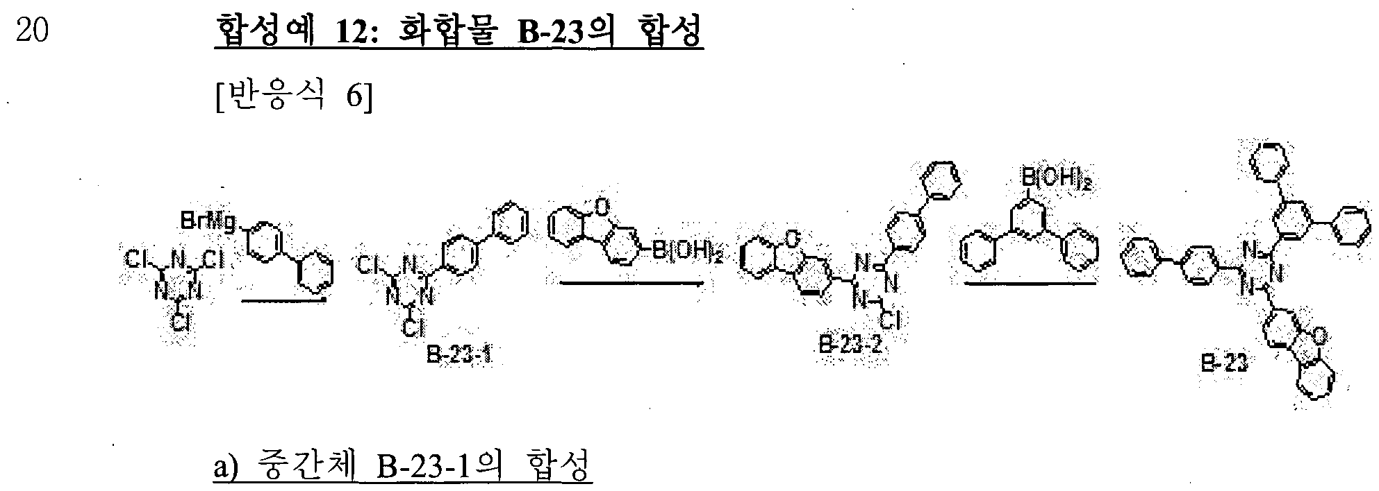
500 mL등근바닥플라스크에 시아누릭클로라이드 15 g(81.34 mmol)을 무수
테트라하이드로퓨란 200 mL에 녹이고, 질소대기하에서 4-바이페닐 마그네슘브로마이드 용액 (0.5M 테트라하이드로퓨란 ) 1 당량을 0°C에서 적가하고 서서히 상온으로 올린다. 상온에서 1 시간 동안 교반한 후, 반웅액을 얼음물 500 mL에 넣고 층분리시킨다. 유기층을 분리하고 무수 황산마그네슘을 처리하고 농축한다. 농축된 잔사를 테트라하이드로퓨란과 메탄을로 재결정하여 중간체 B-23-1을 17.2 g 얻었다.
b) 중간체 B-23-2의 합성
중간체 B-23-1을사용하여 상기 합성예 C의 a)와 같은 방법을 사용하여 중간체 B-23-2을 합성하였다.
c) 화합물 B-23의 합성
중간체 B-23-2와 1.1 당량의 3,5-다이페닐벤젠보론산을사용하여 상기 합성예 C의 b)와 같은 방법으로 화합물 B-23을 합성하였다.
LC/MS calculated for: C45H29N30 Exact Mass: 627.2311 found for 628.24 [M+H] 합성예 13: 화합물 B-24의 합성
.[반웅식 7]

중간체 B-23-2와 U 당량의 B-[l,l':4',l"-Terphenyl]-3-yl boiOnic acid을 사용하여 상기 합성예 C의 b)와 같은 방법으로 화합물 B-24를 합성하였다.
LC/MS calculated for: C45H29N30 Exact Mass: 627.2311 found for 628.24 [M+H] 합성예 14: 화합물 B-20의 합성

중간체 B-17-1와 1.1 당량의 (5'-phenyl[l,r:3',r-terphenyl]-4-yl)-boiOnic acid(C AS No.: 491612-72-7)을사용하여 상기 합성예 C의 b)와 같은 방법으로 화합물 B-20을 합성하였다.
LC/MS calculated for: C45H29N30 Exact Mass: 627.2311 found for 628.24 [M+H] 합성예 15: 화합물 B-기의 합성

a) 중간체 B-71-1의 합성
500 mL의 등근 바닥 플라스크에 3-브로모 -디벤조퓨란 14.06g (56.90mmol), 테트라하이드로퓨란 200 mL, 증류수 100 mL를 넣고, 3'-클로로 -페닐보론산 1 당량 : 테트라키스트리페닐포스핀 팔라듐 0.03 당량, 탄산칼륨 2 당량을 넣고 질소 대기하에서 가열 환류한다. 18 시간후 반웅액을 넁각시키고, 석출된 고체를 여과하고, 물 500 mL로 씻는다. 고체를 모노클로로벤젠 500 mL로 재결정하여 중간체 B-71-1을 12.05 g 얻었다. (수율 76%)
b) 중간체 B-71-2의 합성
500 mL둥근 바닥 플라스크에 상기 합성된 중간체 B-71-1 24.53 g (88.02 mmol)을 디엠에프 250 mL에 넣고, 다이클로로다이페닐포스피노페로센 팔라듐 0.05 당량, 비스피나콜라도 다이보론 1.2 당량, 초산칼륨 2 당량을 넣고 질소
대기하에서 18 시간 동안 가열 환류시켰다. 반웅액을 넁각시키고, 물 1 L에 적하시켜 고체를 잡는다. 얻어진 고체를 끓는 를루엔에 녹여 활섶탄소를 처리 후 실리카겔에서 여과한 후 여액을 농축한다. 농축된 고체를 소량의 핵산과 교반 후, 고체를 여과하여 중간체 B-71-2를 22.81g 얻었다. (수율 70%)
c) 화합물 B-기의 합성
상기 합성한 중간체 B-71-2와
2,4-Bis([l,l'-biphenyl]-4-yl)-6-chloro-l,3,5-triazine을 각각 1.0 당량씩 사용하여 상기 합성예 a)와 같은 방법으로 화합물 B-기을 합성하였다.
LC/MS calculated for: C45H29N30 Exact Mass: 627.2311 found for 628.25 [M+H]
(유기 발광소자의 제작)
실시예 1:
ITO (Indium tin oxide)가 1500 A 두께로 박막 코팅된 유리 기판을 증류수 초음파로 세척하였다. 증류수 세척이 끝나면 이소프로필 알코올, 아세톤, 메탄올 등의 용제로 초음파 세척을 하고 건조시킨 후 플라즈마 세정기로 이송 시킨 다음 산소 플라즈마를 이용하여 상기 기판을 10분간 세정 한후 진공 증착기로 기판을 이송하였다. 이렇게 준비된 ΠΌ투명 전극을 양극으로 사용하여 ITO 기판상부에 화합물 A을 진공 증착하여 700A 두께의 정공 주입층을 형성하고 상기 주입층 상부에 화합물 B를 50 A의 두께로 증착한후, 화합물 C를 1020 A의 두께로 증착하여 정공수송층을 형성하였다. 정공수송층 상부에 화합물 B-23 및 화합물 A-70을 동시에 호스트로 사용하고 도판트로 Ir(ppy)3를 7wt%로 도핑하여 진공 증착으로 400A 두께의 발광층을 형성하였다. 여기서 화합물 B-23과 화합물 A-74는 5:5 중량비로 사용되었으며, 하기 실시예의 경우 별도로 비율을
기술하였다. 이어서 상기 발광층 상부에 화합물 D와 Liq를 동시에 1 :1 비율로 진공 증착하여 300 A 두께의 전자수송층을 형성하고 상기 전자수송층 상부에 Liq 15A과 A1 1200A을 순차적으로 진공 증착하여 음극을 형성함으로써
유기발광소자를 제작하였다.
상기 유기발광소자는 5층의 유기 박막층을 가지는 구조로 되어 있으며, 구체적으로 다음과 같다.
ΠΌ/화합물 A(700A)/화합물 Β(50Α)/화합물 C(1020 A)/EML [화합물
B-23:화합물 A-70:Ir(ppy)3(7wt%)](400A)/화합물 D:Liq(300A)/Liq(15 Α)/Α1(120θΑ)의
구조로 제작하였다.
화합물 A:
N4,N4'-diphenyl-N4,N4'-bis(9-phenyl-9H-carbazol-3-yl)biphenyl-4,4'-diamine
화합물 B: 1,4,5,8,9,11-hexaazatriphenylene-hexacarbonitrile (HAT-CN), 화합물 C:
N-(biphenyl-4-yl)-9,9-dimethyl-N-(4-(9-phenyl-9H-carbazol-3-yl)phenyl)-9H-fluoren-2-amin e
화합물 D: 8-(4-(4,6-di(naphthalen-2-yl)-l,3,5-triazin-2-yl)phenyl)quinolone 실시예 2 내지 6 및 비교예 1 내지 6
하기 표 1에 기재된 바와 같이 게 1 호스트 및 게 2호스트를 사용하여 실시예 1과 동일한 방법으로 실시예 2 내지 6 및 비교예 1 내지 6의
유기발광소자를 제작하였다. ¾ >
실시예 1 내지 실시예 6, 그리고 비교예 1 내지 비교예 6에 따휸 유기 발광소자의 효과를 다음과 같이 평가하였다. 구체적인 측정방법은 하기와 같다.
(1) 구동전압 측정
전류-전압계 (Keithley 2400)를 이용하여 15 mA/cm2에서 각 소자의
구동전압을 측정하여 결과를 얻었다.
(2) 전압변화에 따른 전류밀도의 변화 측정
제조된 유기발광소자에 대해, 전압을 0V부터 10V까지 상승시키면서 전류-전압계 (Keithley 2400)를 이용하여 단위소자에 흐르는 전류값을 측정하고, 측정된 전류값을 면적으로 나누어 결과를 얻었다.
(3) 전압변화에 따른 휘도변화 측정
제조된 유기발광소자에 대해, 전압을 0V부터 10V까지 상승시키면서 휘도계 (Minolta Cs-IOOOA)를 이용하여 그 때의 휘도를 측정하여 결과를 얻었다.
(4) 수명 측정
제조된 유기발광소자에 대해 폴라로닉스 수명측정 시스템을 사용하여 소자를 초기휘도 (cd/m2)를 24000cd/m2로 발광시키고 시간경과에 따른 휘도의 감소를 측정하여 초기 휘도 대비 90%로 휘도가 감소된 시점을 T90 수명으로
측정하였다. (동일 ET 호스트에서, 화합물 C를 사용했을 때의 수명을 100퍼센트로 하여, 상대 퍼센트로 기재함)
【표 1】

표 1을 참고하면, 제 1 호스트와 게 2 호스트를 조합하여 사용하는 경우 side에 페닐 치환기가 있는 화합물은 대칭인 화합물 a 대비 비대칭성 및 dipole moment가 증가하여 결정화를 일으키지 않으며, 보다균일한 막을 성막하여 수명에 좋은 영향을 주며, side 치환기가 페닐인 경우 HOMO 전자구름이 분포하지 않으며, hole이 이동하는 역할을 하지 않는다. 그런데 이 치환기가 너무
bulky해지면, hole이 이동할 때 inter-molecular hole hopping거리가 늘어나 원활한 hole 이동에 방해가 되며 이런 영향으로 인하여 구동이 밀리는 것을 알 수 있다. 본 발명은 상기 실시예들에 한정되는 것이 아니라서로 다른 다양한 형태로 제조될 수 있으며, 본 발명이 속하는 기술분야에서 통상의 지식을 가진 자는 본 발명의 기술적 사상이나 필수적인 특징을 변경하지 않고서 다른 구체적인 형태로 실시될 수 있다는 것을 이해할 수 있을 것이다. 그러므로 이상에서 기술한 실시예들은 모든 면에서 예시적인 것이며 한정적이 아닌 것으로
이해해야만 한다.
【부호의 설명】
100, 200: 유기 발광 소자 105: 유기층
1 10: 음극
120: 양극
130: 발광층
140: 정공 보조충
Claims
【청구항 1】
하기 화학식 1 및 화학식 2의 조합으로 표현되는 제 1 유기 광전자소자용 화합물; 및 하기 화학식 3으로 표현되는 게 2 유기 광전자 소자용 화합물을 포함하는 유기 광전자소자용 조성물:
1] [화학식 2]

상기 화학식 1 내지 화학식 3에서
Ar1 및 Ar2는 각각 독립적으로 치환또는 비치환된 C6 내지 C30 아릴기이고,
R1 내지 R3은 각각 독립적으로, 수소, 중수소 또는 시아노기이고, 상기 화학식 1의 인접한 2개의 *은 상기 화학식 2의 *와 연결되고, 상기 화학식 1에서 상기 화학식 2의 *와 연결되지 않은 *은 각각 독립적으로 CRa이고,
Z1 내지 Z3은 각각 독립적으로 N또는 CRb이고,
Z1 내지 Z3 중 적어도 둘은 N이고,
Ra, Rb 및 R4 내지 R6은 각각 독립적으로, 수소, 중수소, 시아노기, 치환 또는 비치환된 C1 내지 C10 알킬기, 치환또는 비치환된 C6 내지 C20 아릴기, 또는 치환또는 비치환된 C2 내지 C30 헤테로고리기이고,
L1 내지 L5는 각각 독립적으로 단일 결합, 또는 치환또는 비치환된 C6 내지 C30 아릴렌기이고,
X1은 0 또는 S이고,
A1 및 A2는 각각 독립적으로 치환또는 비치환된 C6 내지 C20 아릴기, 또는 치환또는 비치환된 C2 내지 C30 헤테로고리기이다.
【청구항 2】
겨 U항에 있어서,
상기 제 1 유기 광전자소자용 화합물은 하기 화학식 1C로 표현되는 유기
광전자 소자용 조성물:
[화학식 1C]

상기 화학식 1C에서,
Ar1 및 Ar2는 각각 독립적으로 치환또는 비치환된 C6 내지 C30 아릴기이고,
R1 내지 R3은 각각 독립적으로, 수소, 중수소 또는 시아노기이고,
Ral 및 R32는 각각 독립적으로, 수소, 중수소, 시아노기, 치환 또는 비치환된 C1 내지 C10 알킬기, 치환 또는 비치환된 C6 내지 C20 아릴기, 또는 치환 또는 비치환된 C2 내지 C30 헤테로고리기이고,
L1 및 L2는 각각 독립적으로 단일 결합, 또는 치환 또는 비치환된 C6 내지 C30 아릴렌기이다.
【청구항 3】
거 12항에 있어서,
상기 화학식 ic는 하기 화학식 1C-2 또는 화학식 1C-3으로 표현되는 유기 광전자 소자용 조성물:
[화학식 1C-2] [화학식 1C-3]

상기 화학식 1C-2 및 화학식 1C-3에서,
Ar1 및 Ar2는 각각 독립적으로 치환또는 비치환된 C6 내지 C30 아릴기이고,
R1 내지 R3은 각각 독립적으로, 수소, 중수소 또는 시아노기이고,
Ral 및 Ι 는 각각 독립적으로, 수소, 중수소, 시아노기, 치환또는 비치환된 C1 내지 C10 알킬기, 치환또는 비치환된 C6 내지 C20 아릴기, 또는 치환 또는 비치환된 C2 내지 C30 헤테로고리기이고,
L1 및 L2는 각각 독립적으로 단일 결합, 또는 치환또는 비치환된 C6 내지 C30 아릴렌기이다.
【청구항 4】
제 1항에 있어서,
상기 Ar1 및 Ar2는 각각 독립적으로, 치환 또는 비치환된 페닐기, 치환 또는 비치환된 바이페닐기, 치환또는 비치환된 터페닐기, 또는 치환 또는 비치환된 나프틸기인 유기 광전자 소자용 조성물.
【청구항 5】
제 4항에 있어서,
상기 Ar1 및 Ar2는 각각 독립적으로, 하기 그룹 I에 나열된 치환기에서 선택되는 유기 광전자소자용 조성물:

상기 그룹 I에서, *은 각각 L1 및 L2와의 연결 지점이다.
【청구항 6】
제 1항에 있어서,
상기 제 2 유기 광전자 소자용 화합물은 하기 화학식 3-a내지 화학식 3-d 중 어느 하나로 표현되는 유기 광전자 소자용 조성물:
[화학식 3-a] [화학식 3-b]


상기 화학식 3-a내지 화학식 3-d에서,
Z1 내지 Z3은 각각 독립적으로 N또는 CRb이고,
Z1 내지 Z3 중 적어도 둘은 N이고,
Rb 및 R4 내지 R6은 각각 독립적으로, 수소, 중수소, 시아노기, 치환또는 비치환된 C1 내지 C10 알킬기, 치환또는 비치환된 C6 내지 C20 아릴기, 또는 치환또는 비치환된 C2 내지 C30 헤테로고리기이고,
L3 내지 L5는 각각 독립적으로 단일 결합, 또는 치환또는 비치환된 C6 내지 C30 아릴렌기이고, ,
X1은 0 또는 S이고,
A1 및 A2는 각각 독립적으로 치환또는 비치환된 C6 내지 C20 아릴기, 또는 치환 또는 비치환된 C2 내지 C30 헤테로고리기이다.
【청구항 7】
제 1항에 있어서,
상기 게 2 유기 광전자 소자용 화합물은 하기 화학식 3- 1로 표현되는 유기 광전자 소자용 조성물:
[화학식 3- 1 ]
상기 화학식 3- I에서,
Z1 내지 Z3은 각각 독립적으로 N또는 CRb이고:
Z1 내지 Z3 중 적어도 둘은 N이고,
Rb 및 R4 내지 R8은 각각 독립적으로, 수소, 중수소, 시아노기, 치환또는 비치환된 C1 내지 C10 알킬기, 치환 또는 비치환된 C6 내지 C20 아릴기, 또는 치환또는 비치환된 C2 내지 C30 헤테로고리기이고,
L3 내지 L5는 각각 독립적으로 단일 결합, 또는 치환또는 비치환된 C6 내지 C30 아릴렌기이고,
X1은 0또는 S이고,
A2는 치환 또는 비치환된 C6 내지 C20 아릴기, 또는 치환또는 비치환된 C2 내지 C30 헤테로고리기이다.
【청구항 8】
게 7항에 있어서,
상기 화학식 3- 1은 하기 화학식 3- 1 -1 내지 화학식 3- 1 -3 중 어느 하나로 표현되는 유기 광전자 소자용 조성물:

상기 화학식 3- 1 -1 내지 화학식 3- 1 -3에서,
Ar3은 치환또는 비치환된 C6 내지 C20 아릴기이고,
Z1 내지 Z6은 각각 독립적으로 N또는 CRb이고,
Z1 내지 Z3 중 적어도 둘은 N이고,
Z4 내지 Z6 중 적어도 둘은 N이고,
Rb Rc, Rd, Re 및 R4 내지 R8은 각각 독립적으로, 수소, 중수소, 시아노기, 치환 또는 비치환된 C1 내지 C10 알킬기, 치환또는 비치환된 C6 내지 C20 아릴기, 또는 치환 또는 비치환된 C2 내지 C30 헤테로고리기이고,
L3 내지 L5는 각각 독립적으로 단일 결합, 또는 치환또는 비치환된 C6 내지 C30 아릴렌기이고,
X1 및 X2는 각각 독립적으로 0또는 S이다.
【청구항 9】
제 1항에 있어서,
상기 화학식 3의 A1은 치환또는 비치환된 C6 내지 C20 아릴기이고,
상기 화학식 3의 A2는 치환 또는 비치환된 페닐기, 치환 또는 비치환된 바이페닐기, 치환또는 비치환된 나프틸기, 치환또는 비치환된 터페닐기, 치환 또는 비치환된 쿼터페닐기, 치환또는 비치환된 디벤조퓨란일기, 치환또는 비치환된 디벤조티오펜일기, 치환 또는 비치환된 피리미디닐기, 또는 치환또는 비치환된 트리아지닐기인 유기 광전자 소자용 조성물.
【청구항 10】
제 9항에 있어서,
상가화학식 3의 A1은 하기 그룹 Π에 나열된 치환기에서 선택되고, 상기 화학식 3의 A2는 하기 그룹 m에 나열된 치환기에서 선택되는 유기 광전자 소자용 조성물:

[그룹 m]

상기 그룹 m에서, *은 L5와의 연결 지점이다.
【청구항 111
게 1항에 있어서,
상기 게 1 유기 광전자 소자용 화합물과 상기 게 2 유기 광전자 소자용 화합물은 3:7 내지 6:4의 중량비로 포함되는 유기 광전자 소자용 조성물.
【청구항 12]
제 11항에 있어서,
상기 게 1 유기 광전자 소자용 화합물과 상기 게 2 유기 광전자 소자용 화합물은 5:5의 중량비로 포함되는 유기 광전자 소자용 조성물.
【청구항 13】
서로 마주하는 양극과 음극, 그리고
상기 양극과 상기 음극사이에 위치하는 적어도 한 층의 유기층을 포함하고,
상기 제 1항 내지 제 12항 중 어느 한 항에 따른 유기 광전자 소자용 조성물을 포함하는 유기 광전자 소자.
【청구항 14】
제 13항에 있어서,
상기 유기층은 발광층을 포함하고,
상기 유기 광전자 소자용 조성물은 상기 발광층의 호스트로서 포함되는 유기 광전자 소자.
【청구항 15】
제 13항에 따른 유기 광전자 소자를 포함하는 표시장치.
Priority Applications (4)
| Application Number | Priority Date | Filing Date | Title |
|---|---|---|---|
| JP2020521416A JP6934568B2 (ja) | 2017-10-20 | 2018-10-10 | 有機光電子素子用組成物、有機光電子素子および表示装置 |
| EP18869382.4A EP3680309B1 (en) | 2017-10-20 | 2018-10-10 | Composition for organic optoelectronic element, organic optoelectronic element, and display device |
| CN201880067911.2A CN111247226B (zh) | 2017-10-20 | 2018-10-10 | 用于有机光电元件的组合物、有机光电元件和显示装置 |
| US16/647,145 US11659765B2 (en) | 2017-10-20 | 2018-10-10 | Composition for organic optoelectronic element, organic optoelectronic element, and display device |
Applications Claiming Priority (2)
| Application Number | Priority Date | Filing Date | Title |
|---|---|---|---|
| KR10-2017-0136649 | 2017-10-20 | ||
| KR1020170136649A KR102160270B1 (ko) | 2017-10-20 | 2017-10-20 | 유기 광전자 소자용 조성물, 유기 광전자 소자 및 표시 장치 |
Publications (1)
| Publication Number | Publication Date |
|---|---|
| WO2019078536A1 true WO2019078536A1 (ko) | 2019-04-25 |
Family
ID=66174601
Family Applications (1)
| Application Number | Title | Priority Date | Filing Date |
|---|---|---|---|
| PCT/KR2018/011898 Ceased WO2019078536A1 (ko) | 2017-10-20 | 2018-10-10 | 유기 광전자 소자용 조성물, 유기 광전자 소자 및 표시 장치 |
Country Status (6)
| Country | Link |
|---|---|
| US (1) | US11659765B2 (ko) |
| EP (1) | EP3680309B1 (ko) |
| JP (1) | JP6934568B2 (ko) |
| KR (1) | KR102160270B1 (ko) |
| CN (1) | CN111247226B (ko) |
| WO (1) | WO2019078536A1 (ko) |
Families Citing this family (4)
| Publication number | Priority date | Publication date | Assignee | Title |
|---|---|---|---|---|
| WO2021033724A1 (ja) | 2019-08-19 | 2021-02-25 | 出光興産株式会社 | 化合物、有機エレクトロルミネッセンス素子用材料、有機エレクトロルミネッセンス素子及び電子機器 |
| KR102421843B1 (ko) * | 2020-02-10 | 2022-07-15 | 단국대학교 천안캠퍼스 산학협력단 | 피리미딘을 포함하는 화합물 및 이를 함유하는 유기발광다이오드 |
| KR102739126B1 (ko) * | 2020-06-10 | 2024-12-05 | 삼성전자주식회사 | 조성물 및 이를 포함한 유기 발광 소자 |
| KR102761653B1 (ko) | 2020-09-04 | 2025-01-31 | 삼성에스디아이 주식회사 | 유기 광전자 소자용 조성물, 유기 광전자 소자 및 표시 장치 |
Citations (6)
| Publication number | Priority date | Publication date | Assignee | Title |
|---|---|---|---|---|
| US5942340A (en) | 1997-10-02 | 1999-08-24 | Xerox Corporation | Indolocarbazole electroluminescent devices |
| US20170025618A1 (en) * | 2015-04-06 | 2017-01-26 | Universal Display Corporation | Organic Electroluminescent Materials and Devices |
| WO2017115608A1 (ja) * | 2015-12-28 | 2017-07-06 | コニカミノルタ株式会社 | π共役系化合物、有機エレクトロルミネッセンス素子材料、発光材料、電荷輸送材料、発光性薄膜、有機エレクトロルミネッセンス素子、表示装置及び照明装置 |
| KR20170086211A (ko) * | 2016-01-18 | 2017-07-26 | 에스에프씨 주식회사 | 유기발광 화합물 및 이를 포함하는 유기발광소자 |
| KR20170101021A (ko) * | 2016-02-26 | 2017-09-05 | 삼성에스디아이 주식회사 | 유기 화합물, 유기 광전자 소자 및 표시 장치 |
| US20170271598A1 (en) * | 2016-03-16 | 2017-09-21 | Universal Display Corporation | Organic electroluminescent materials and devices |
Family Cites Families (11)
| Publication number | Priority date | Publication date | Assignee | Title |
|---|---|---|---|---|
| US6900458B2 (en) * | 2003-02-21 | 2005-05-31 | Universal Display Corporation | Transflective display having an OLED backlight |
| JPWO2007063796A1 (ja) | 2005-12-01 | 2009-05-07 | 新日鐵化学株式会社 | 有機電界発光素子 |
| KR20130094903A (ko) * | 2012-02-17 | 2013-08-27 | 롬엔드하스전자재료코리아유한회사 | 신규한 유기 발광 화합물 |
| EP2821459B1 (en) | 2013-07-01 | 2017-10-04 | Cheil Industries Inc. | Composition and organic optoelectric device and display device |
| KR102209703B1 (ko) | 2014-02-10 | 2021-01-28 | 삼성전자주식회사 | 하프늄 텔루라이드계 층상 구조 화합물, 이를 포함한 투명 도전막, 및 이를 포함한 전자 소자 |
| KR20150108330A (ko) * | 2014-03-17 | 2015-09-25 | 롬엔드하스전자재료코리아유한회사 | 전자 버퍼 재료 및 이를 포함하는 유기 전계 발광 소자 |
| KR101754715B1 (ko) * | 2014-04-08 | 2017-07-10 | 롬엔드하스전자재료코리아유한회사 | 복수종의 호스트 재료와 이를 포함하는 유기 전계 발광 소자 |
| KR102491209B1 (ko) | 2014-04-29 | 2023-01-26 | 롬엔드하스전자재료코리아유한회사 | 복수종의 호스트 재료 및 이를 포함하는 유기 전계 발광 소자 |
| KR102613166B1 (ko) * | 2015-03-13 | 2023-12-14 | 롬엔드하스전자재료코리아유한회사 | 복수 종의 호스트 재료 및 이를 포함하는 유기 전계 발광 소자 |
| US10593890B2 (en) | 2015-04-06 | 2020-03-17 | Universal Display Corporation | Organic electroluminescent materials and devices |
| KR102591635B1 (ko) * | 2015-10-27 | 2023-10-20 | 삼성디스플레이 주식회사 | 유기 발광 소자 |
-
2017
- 2017-10-20 KR KR1020170136649A patent/KR102160270B1/ko active Active
-
2018
- 2018-10-10 US US16/647,145 patent/US11659765B2/en active Active
- 2018-10-10 CN CN201880067911.2A patent/CN111247226B/zh active Active
- 2018-10-10 WO PCT/KR2018/011898 patent/WO2019078536A1/ko not_active Ceased
- 2018-10-10 JP JP2020521416A patent/JP6934568B2/ja active Active
- 2018-10-10 EP EP18869382.4A patent/EP3680309B1/en active Active
Patent Citations (6)
| Publication number | Priority date | Publication date | Assignee | Title |
|---|---|---|---|---|
| US5942340A (en) | 1997-10-02 | 1999-08-24 | Xerox Corporation | Indolocarbazole electroluminescent devices |
| US20170025618A1 (en) * | 2015-04-06 | 2017-01-26 | Universal Display Corporation | Organic Electroluminescent Materials and Devices |
| WO2017115608A1 (ja) * | 2015-12-28 | 2017-07-06 | コニカミノルタ株式会社 | π共役系化合物、有機エレクトロルミネッセンス素子材料、発光材料、電荷輸送材料、発光性薄膜、有機エレクトロルミネッセンス素子、表示装置及び照明装置 |
| KR20170086211A (ko) * | 2016-01-18 | 2017-07-26 | 에스에프씨 주식회사 | 유기발광 화합물 및 이를 포함하는 유기발광소자 |
| KR20170101021A (ko) * | 2016-02-26 | 2017-09-05 | 삼성에스디아이 주식회사 | 유기 화합물, 유기 광전자 소자 및 표시 장치 |
| US20170271598A1 (en) * | 2016-03-16 | 2017-09-21 | Universal Display Corporation | Organic electroluminescent materials and devices |
Non-Patent Citations (1)
| Title |
|---|
| See also references of EP3680309A4 |
Also Published As
| Publication number | Publication date |
|---|---|
| JP2021500743A (ja) | 2021-01-07 |
| KR102160270B1 (ko) | 2020-09-25 |
| EP3680309A1 (en) | 2020-07-15 |
| CN111247226B (zh) | 2024-04-26 |
| EP3680309A4 (en) | 2021-06-02 |
| JP6934568B2 (ja) | 2021-09-15 |
| US11659765B2 (en) | 2023-05-23 |
| CN111247226A (zh) | 2020-06-05 |
| US20210050526A1 (en) | 2021-02-18 |
| KR20190044338A (ko) | 2019-04-30 |
| EP3680309B1 (en) | 2023-05-03 |
Similar Documents
| Publication | Publication Date | Title |
|---|---|---|
| TWI672359B (zh) | 有機光電裝置及使用其之顯示裝置 | |
| CN110294703B (zh) | 用于有机光电器件的组合物、有机光电器件及显示器件 | |
| TWI679787B (zh) | 有機光電裝置及使用其之顯示裝置 | |
| CN104703969B (zh) | 荧蒽化合物及包含其的有机电子器件 | |
| TWI682934B (zh) | 新式雜環化合物以及使用此雜環化合物的有機發光裝置 | |
| CN103608429B (zh) | 化合物及使用所述化合物的有机电子器件 | |
| TWI703203B (zh) | 有機光電裝置以及顯示裝置 | |
| TWI500604B (zh) | 有機光電元件用組成物及有機光電元件及顯示元件 | |
| TWI641607B (zh) | 用於有機光電裝置的化合物、用於有機光電裝置的組成物以及有機光電裝置及顯示裝置 | |
| CN109790458B (zh) | 用于有机光电二极管的化合物、用于有机光电二极管的组合物、有机光电二极管和显示装置 | |
| KR102275343B1 (ko) | 유기 광전자 소자용 조성물, 유기 광전자 소자 및 표시 장치 | |
| CN112563430A (zh) | 用于有机光电装置的有机合金、有机光电装置及显示装置 | |
| KR101442982B1 (ko) | 다환 화합물 및 이를 포함하는 유기 전자 소자 | |
| CN105358654A (zh) | 有机电致发光化合物和包含所述化合物的有机电致发光装置 | |
| WO2016024745A2 (ko) | 화합물, 이를 포함하는 유기 광전자 소자 및 표시장치 | |
| TWI659027B (zh) | 用於有機光電裝置的化合物、用於有機光電裝置的組成物、包含所述化合物及組成物的有機光電裝置以及顯示裝置 | |
| JP7303336B2 (ja) | 有機光電子素子用化合物、有機光電子素子用組成物、有機光電子素子および表示装置 | |
| CN107619410A (zh) | 化合物及包含其的有机电子元件 | |
| TWI796474B (zh) | 用於有機光電裝置的組成物、有機光電裝置及顯示裝置 | |
| CN110872511A (zh) | 用于有机光电器件的组合物、有机光电器件及显示器件 | |
| CN112574210A (zh) | 用于有机光电装置的化合物、用于有机光电装置的组合物、有机光电装置及显示装置 | |
| WO2019078536A1 (ko) | 유기 광전자 소자용 조성물, 유기 광전자 소자 및 표시 장치 | |
| KR20180044832A (ko) | 유기 발광 소자 | |
| KR20180103352A (ko) | 유기 발광 소자 | |
| KR20200068568A (ko) | 신규한 화합물 및 이를 포함하는 유기발광 소자 |
Legal Events
| Date | Code | Title | Description |
|---|---|---|---|
| 121 | Ep: the epo has been informed by wipo that ep was designated in this application |
Ref document number: 18869382 Country of ref document: EP Kind code of ref document: A1 |
|
| ENP | Entry into the national phase |
Ref document number: 2018869382 Country of ref document: EP Effective date: 20200406 |
|
| ENP | Entry into the national phase |
Ref document number: 2020521416 Country of ref document: JP Kind code of ref document: A |
|
| NENP | Non-entry into the national phase |
Ref country code: DE |