WO2019082395A1 - 空調システム - Google Patents
空調システムInfo
- Publication number
- WO2019082395A1 WO2019082395A1 PCT/JP2017/038977 JP2017038977W WO2019082395A1 WO 2019082395 A1 WO2019082395 A1 WO 2019082395A1 JP 2017038977 W JP2017038977 W JP 2017038977W WO 2019082395 A1 WO2019082395 A1 WO 2019082395A1
- Authority
- WO
- WIPO (PCT)
- Prior art keywords
- air
- mode
- air conditioning
- outside
- control device
- Prior art date
- Legal status (The legal status is an assumption and is not a legal conclusion. Google has not performed a legal analysis and makes no representation as to the accuracy of the status listed.)
- Ceased
Links
Images


Classifications
-
- B—PERFORMING OPERATIONS; TRANSPORTING
- B60—VEHICLES IN GENERAL
- B60H—ARRANGEMENTS OF HEATING, COOLING, VENTILATING OR OTHER AIR-TREATING DEVICES SPECIALLY ADAPTED FOR PASSENGER OR GOODS SPACES OF VEHICLES
- B60H1/00—Heating, cooling or ventilating devices
- B60H1/00642—Control systems or circuits; Control members or indication devices for heating, cooling or ventilating devices
- B60H1/00735—Control systems or circuits characterised by their input, i.e. by the detection, measurement or calculation of particular conditions, e.g. signal treatment, dynamic models
- B60H1/008—Control systems or circuits characterised by their input, i.e. by the detection, measurement or calculation of particular conditions, e.g. signal treatment, dynamic models the input being air quality
-
- B—PERFORMING OPERATIONS; TRANSPORTING
- B60—VEHICLES IN GENERAL
- B60H—ARRANGEMENTS OF HEATING, COOLING, VENTILATING OR OTHER AIR-TREATING DEVICES SPECIALLY ADAPTED FOR PASSENGER OR GOODS SPACES OF VEHICLES
- B60H1/00—Heating, cooling or ventilating devices
- B60H1/00642—Control systems or circuits; Control members or indication devices for heating, cooling or ventilating devices
- B60H1/00814—Control systems or circuits characterised by their output, for controlling particular components of the heating, cooling or ventilating installation
- B60H1/00821—Control systems or circuits characterised by their output, for controlling particular components of the heating, cooling or ventilating installation the components being ventilating, air admitting or air distributing devices
- B60H1/00835—Damper doors, e.g. position control
- B60H1/00849—Damper doors, e.g. position control for selectively commanding the induction of outside or inside air
-
- B—PERFORMING OPERATIONS; TRANSPORTING
- B60—VEHICLES IN GENERAL
- B60H—ARRANGEMENTS OF HEATING, COOLING, VENTILATING OR OTHER AIR-TREATING DEVICES SPECIALLY ADAPTED FOR PASSENGER OR GOODS SPACES OF VEHICLES
- B60H3/00—Other air-treating devices
- B60H3/0085—Smell or pollution preventing arrangements
-
- B—PERFORMING OPERATIONS; TRANSPORTING
- B60—VEHICLES IN GENERAL
- B60H—ARRANGEMENTS OF HEATING, COOLING, VENTILATING OR OTHER AIR-TREATING DEVICES SPECIALLY ADAPTED FOR PASSENGER OR GOODS SPACES OF VEHICLES
- B60H1/00—Heating, cooling or ventilating devices
- B60H1/00642—Control systems or circuits; Control members or indication devices for heating, cooling or ventilating devices
- B60H1/00735—Control systems or circuits characterised by their input, i.e. by the detection, measurement or calculation of particular conditions, e.g. signal treatment, dynamic models
- B60H1/00785—Control systems or circuits characterised by their input, i.e. by the detection, measurement or calculation of particular conditions, e.g. signal treatment, dynamic models by the detection of humidity or frost
-
- B—PERFORMING OPERATIONS; TRANSPORTING
- B60—VEHICLES IN GENERAL
- B60H—ARRANGEMENTS OF HEATING, COOLING, VENTILATING OR OTHER AIR-TREATING DEVICES SPECIALLY ADAPTED FOR PASSENGER OR GOODS SPACES OF VEHICLES
- B60H1/00—Heating, cooling or ventilating devices
- B60H1/02—Heating, cooling or ventilating devices the heat being derived from the propulsion plant
- B60H1/03—Heating, cooling or ventilating devices the heat being derived from the propulsion plant and from a source other than the propulsion plant
- B60H1/039—Heating, cooling or ventilating devices the heat being derived from the propulsion plant and from a source other than the propulsion plant from air leaving the interior of the vehicle, i.e. heat recovery
-
- B—PERFORMING OPERATIONS; TRANSPORTING
- B60—VEHICLES IN GENERAL
- B60H—ARRANGEMENTS OF HEATING, COOLING, VENTILATING OR OTHER AIR-TREATING DEVICES SPECIALLY ADAPTED FOR PASSENGER OR GOODS SPACES OF VEHICLES
- B60H3/00—Other air-treating devices
- B60H3/06—Filtering
- B60H2003/0683—Filtering the quality of the filter or the air being checked
-
- B—PERFORMING OPERATIONS; TRANSPORTING
- B60—VEHICLES IN GENERAL
- B60H—ARRANGEMENTS OF HEATING, COOLING, VENTILATING OR OTHER AIR-TREATING DEVICES SPECIALLY ADAPTED FOR PASSENGER OR GOODS SPACES OF VEHICLES
- B60H3/00—Other air-treating devices
- B60H3/06—Filtering
Definitions
- the present invention relates to an air conditioning system which is mounted on a vehicle and has a configuration capable of switching air conditioning of the interior of the vehicle between inside air circulation and outside air introduction.
- the present invention has been made to solve the problems as described above, and it is an object of the present invention to obtain an air conditioning system that realizes air conditioning control that improves the comfort of the interior of a vehicle.
- the air conditioning system is an air conditioning system mounted on a vehicle, and detects the degree of contamination of outside air that is air outside the vehicle and the degree of contamination of inside air that is air inside the vehicle. It has a detector, an air conditioning control device that controls air conditioning by switching the air conditioning mode of the vehicle to an inside air circulation mode that circulates inside air, and an outside air introduction mode that introduces outside air into the room and discharges the inside air to the outside.
- the air conditioning control device determines the degree of contamination of the outside air acquired from the air pollution degree detector and whether to switch the air conditioning mode from the outside air introduction mode to the inside air circulation mode.
- the air conditioning mode is switched from the outside air introduction mode to the inside air circulation mode if the outside air pollution degree exceeds the outside air pollution degree threshold, and the air conditioning mode is the inside air circulation mode. If the air pollution degree is lower than the air pollution degree threshold value for determining whether the air conditioning mode is to be switched from the air circulation mode to the air introduction mode or not, If the contamination degree exceeds the inside air pollution degree threshold, the air conditioning mode is switched from the inside air circulation mode to the outside air introduction mode.
- the air conditioning of the room is alternately switched to the inside air circulation and the outside air introduction based on the detection results of the air pollution degree detector which respectively detects the outside air pollution degree and the inside air pollution degree.
- the air pollution degree detector which respectively detects the outside air pollution degree and the inside air pollution degree.
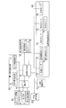
- FIG. 1 is a block diagram showing a vehicle 1 on which an air conditioning system according to Embodiment 1 of the present invention is mounted.
- FIG. 2 is a configuration diagram showing the air conditioning system in the first embodiment of the present invention.
- the air conditioning system includes a heat exchange ventilator 30 having an air supply passage 2, an exhaust passage 3, a heat exchanger 4 and a blower fan 8, an HVAC unit 5, a gate valve 6, and internal / external air switching.
- An air conditioner 40 having a valve 7, an air conditioning controller 9, an outdoor thermometer 10 and a fogging information detector 50 having an indoor temperature and humidity meter 11, a dust sensor 12, an outdoor odor sensor 13, an indoor odor sensor 14, an air pollution degree detector 60 having a VOC sensor 15, a NOx sensor 16, an SOx sensor 17, and a CO2 sensor 18, an air conditioner control device 19, an air cleaner 20, and a vehicle control device 21.
- the air supply path 2 is an air path for supplying air outside the vehicle 1 (referred to as outside air) into the room of the vehicle 1 when the air conditioning mode is the outside air introduction mode.
- the exhaust passage 3 is an air passage for exhausting the air inside the vehicle 1 (referred to as inside air) to the outside when the air conditioning mode is the outside air introduction mode.
- the air conditioning mode is the inside air circulation mode
- the air conditioning mode is the outside air introduction mode
- the outside air is introduced into the room and the inside air is discharged outside the room.
- the heat exchanger 4 exchanges heat between the outside air introduced into the room and the inside air discharged outside when the air conditioning mode is the outside air introduction mode. That is, when the air conditioning mode is the open air introduction mode, the heat exchanger 4 exchanges heat between the air supplied from the outside to the air supply passage 2 and the air exhausted from the room to the exhaust passage 3. For example, the heat exchanger 4 performs heat exchange by causing the air flowing in from the outlet of the air supply passage 2 and the air flowing in from the inlet of the exhaust passage 3 to cross or face each other for contact.
- a HVAC (Heating Ventilation and Air Conditioning) unit 5 includes a refrigerant heat exchanger (not shown) that exchanges heat between refrigerant and air, and a blower fan (not shown) that causes air after heat exchange from the refrigerant heat exchanger to flow into the room Not shown).
- the blower fan of the HVAC unit 5 is configured to be able to compensate for the pressure loss of the heat exchanger 4. In order to compensate for the pressure loss of the heat exchanger 4, an additional fan may be provided in addition to the enlargement of the blower fan of the HVAC unit 5.
- the gate valve 6 is adjusted in open / close degree by driving a servomotor (not shown) according to the control from the air conditioner control device 19 so that the open / close operation is performed.
- An air passage when air flows from the HVAC unit 5 into the room is determined according to the gate valve 6 on which the opening and closing operation is performed.
- the open / close operation of the inside / outside air switching valve 7 is adjusted by driving the servomotor (not shown) according to the control from the air conditioner control device 19 so that the degree of opening / closing is adjusted.
- the inside / outside air switching valve 7 blocks the air path from the heat exchanger 4 to the HVAC unit 5 and passes the air path from the room to the HVAC unit 5. Thus, air does not flow from the heat exchanger 4 to the HVAC unit 5, and air flows from the room to the HVAC unit 5. That is, the HVAC unit 5 takes in the inside air when the air conditioning mode is the inside air circulation mode.
- the inside / outside air switching valve 7 blocks the air passage from the room to the HVAC unit 5 and passes the air passage from the heat exchanger 4 to the HVAC unit 5. As a result, no air flows from the room to the HVAC unit 5, and air flows from the heat exchanger 4 to the HVAC unit 5. That is, when the air conditioning mode is the outside air introduction mode, the HVAC unit 5 takes in air passing through the heat exchanger 4 from the outside via the air supply passage 2.
- the blower fan 8 operates only when the air conditioning mode is the open air introduction mode. By operating the blower fan 8, the inside air is exhausted from the exhaust passage 3 to the outside via the heat exchanger 4. The operation of the blower fan 8 is controlled to maintain the same atmospheric pressure outside and inside the room.
- the fogging information detector 50 detects fogging information for determining whether the windshield of the vehicle 1 is fogged.
- the fogging information detector 50 is configured to include an outdoor thermometer 10 that detects an outdoor temperature, and an indoor temperature and humidity meter 11 that detects an indoor temperature and humidity.
- the air pollution degree detector 60 detects the degree of outside air pollution and the degree of inside air pollution, respectively.
- the air pollution degree detector 60 includes a dust sensor 12, an outdoor odor sensor 13, an indoor odor sensor 14, a VOC sensor 15, a NOx sensor 16, an SOx sensor 17, and a CO2 sensor 18. .
- the dust sensor 12 detects the dust concentration in the open air.
- the outdoor odor sensor 13 detects the odor concentration in the open air.
- the NOx sensor 16 detects the concentration of NOx (nitrogen oxide) in the outside air.
- the SOx sensor 17 detects the concentration of SOx (sulfurized oxide) in the open air.
- the indoor odor sensor 14 detects the odor concentration in the inside air.
- the VOC sensor 15 detects the concentration of volatile organic compounds (VOC) in the inside air.
- the CO2 sensor 18 detects the concentration of CO2 (carbon dioxide) in the inside air.
- Each of the outdoor thermometer 10, the dust sensor 12, the outdoor odor sensor 13, the NOx sensor 16 and the SOx sensor 17 may be provided at any position where it can be exposed to the outside air.
- these sensors are provided in the hood of the vehicle 1 or at the inlet of the air supply passage 2.
- Each of the indoor-side thermo-hygrometer 11, the indoor-side odor sensor 14, the VOC sensor 15, and the CO2 sensor 18 may be provided at any position as long as the inside air can be touched.
- these sensors are provided in the console of the vehicle 1 or at the inlet of the exhaust line 3.
- these sensors may be provided in the console of the vehicle 1 or at the inlet of the exhaust line 3.
- you may utilize the existing thing.
- the air conditioning control device 9 controls the air conditioning by switching the air conditioning mode between an inside air circulation mode for circulating inside air and an outside air introduction mode for introducing outside air into the room and discharging the inside air to the outside.
- the air conditioning control device 9 determines the degree of pollution of outside air acquired from the air pollution degree detector 60 and whether to switch the air conditioning mode from the outside air introduction mode to the inside air circulation mode And the ambient air pollution degree threshold for comparison.
- the air conditioning control device 9 switches the air conditioning mode from the outside air introduction mode to the inside air circulation mode if the degree of outside air pollution exceeds the outside air pollution degree threshold as a result of the comparison.
- the air conditioning controller 9 determines the degree of pollution of inside air acquired from the air pollution degree detector 60 and whether to switch the air conditioning mode from the inside air circulation mode to the outside air introduction mode Compare with the inside air pollution degree threshold of The air conditioning control device 9 switches the air conditioning mode from the inside air circulation mode to the outside air introduction mode if the degree of contamination of the inside air exceeds the inside air contamination degree threshold as a result of the comparison.
- the air conditioning control device 9 determines whether the windshield is cloudy based on the fogging information acquired from the fogging information detector 50. If the air conditioning control device 9 determines that the windshield is cloudy as a result of the determination, it switches the air conditioning mode from the inside air circulation mode to the outside air introduction mode.
- the air conditioner control device 19 controls the operations of the HVAC unit 5, the gate valve 6, and the inside / outside air switching valve 7.
- the air cleaner 20 purifies the inside air to be circulated when the air conditioning mode is the inside air circulation mode. That is, the air cleaner 20 cleans the air flowing to the HVAC unit 5. For example, the air cleaner 20 purifies air by decomposing the smell in the air or adsorbing the dust in the air using the ions generated by the high voltage discharge. As a result, when the air conditioning mode is the inside air circulation mode, the unpleasant component contained in the inside air is removed, and the comfortable environment in the room can be maintained.
- the vehicle control device 21 switches the operation mode of the vehicle 1 to an automatic operation mode in which autonomous driving is performed on behalf of the driver of the vehicle, and a manual operation mode in which the driver itself performs driving to control the driving.
- the vehicle control device 21 is provided in the vehicle 1 and is based on detection results of various sensors (not shown) that detect the situation around the vehicle. The driving of the vehicle 1 is controlled.
- the air conditioning control device 9 is communicably connected to each of the air conditioner control device 19, the air cleaner 20, the vehicle control device 21, the heat exchange ventilator 30, the fogging information detector 50 and the air pollution degree detector 60. Be done.
- the air conditioner control device 19 is communicably connected to each of the HVAC unit 5, the gate valve 6 and the inside / outside air switching valve 7.
- the air conditioning control device 9 selects either the inside air circulation mode or the outside air introduction mode as the air conditioning mode
- the air conditioner control device 19 selects the HVAC unit 5, the gate valve 6, and the inside / outside air switching valve 7 according to the selected mode. Control each of the
- each of the air conditioning control device 9, the air conditioner control device 19 and the vehicle control device 21 stores a microcomputer that executes arithmetic processing, a ROM (Read Only Memory) that stores data such as program data and fixed value data, This is realized by a RAM (Random Access Memory) or the like, which updates the data in question and is sequentially rewritten.
- each of the air conditioning control device 9, the air conditioner control device 19, and the vehicle control device 21 is an integrated circuit, and is configured of, for example, an application specific integrated circuit (ASIC) or a field programmable gate array (FPGA). The functions of the air conditioning control device 9, the air conditioning control device 19 and the vehicle control device 21 may be integrated into one integrated circuit.
- ASIC application specific integrated circuit
- FPGA field programmable gate array
- the air conditioning control device 9 is a sensor for comparing the detected values of the dust sensor 12, the outdoor odor sensor 13, the indoor odor sensor 14, the VOC sensor 15, the NOx sensor 16, the SOx sensor 17, and the CO 2 sensor 18.
- the air conditioning control device 9 corresponds to the threshold corresponding to the dust sensor 12 (referred to as a dust threshold), the threshold corresponding to the outdoor odor sensor 13 (referred to as an outdoor odor threshold), and the indoor odor sensor 14 Threshold (referred to as the indoor odor threshold), the threshold corresponding to the VOC sensor 15 (referred to as the VOC threshold), the threshold corresponding to the NOx sensor 16 (NOx threshold), and the threshold corresponding to the SOx sensor 17 (SOx threshold) And a threshold (referred to as a CO2 threshold) corresponding to the CO2 sensor 18 are stored.
- the above threshold stored for each sensor is set in advance, and is set to, for example, a value that can be detected by a human by a sensor detection target, or an environmental reference value corresponding to a detection target of the sensor.
- the size of the particle size of dust that human beings can easily detect is 10 ⁇ m or more. Most of the dust with a particle size of 10 ⁇ m or more can be removed by an air conditioner filter. Therefore, the detection target of the dust sensor 12 is dust having a particle size of less than 10 ⁇ m. Note that dust of a plurality of types of particle sizes may be used as a detection target of the dust sensor 12. In this case, since the effect on the human body differs depending on the particle size of the dust, a threshold is set for each type of particle size.
- the VOC sensor 15 detects the concentration of a chemical substance such as formaldehyde, toluene, xylene, ethylbenzene, styrene, dibutyl phthalate, tetradecane, bis phthalate, and acetaldehyde.
- a chemical substance such as formaldehyde, toluene, xylene, ethylbenzene, styrene, dibutyl phthalate, tetradecane, bis phthalate, and acetaldehyde.
- a plurality of chemical substances may be detected by the VOC sensor 15.
- a threshold is set for each type of chemical substance.
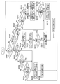
- FIG. 3 is a flowchart showing a series of processing of the air conditioning system in the first embodiment of the present invention.
- step S001 the air conditioning control device 9 acquires the operating condition of the air conditioner 40 from the air conditioner control device 19, and determines whether the air conditioning mode is the open air introduction mode from the acquired operating condition. If it is determined that the air conditioning mode is the outside air introduction mode, the process proceeds to step S002, and if the air conditioning mode is not the outside air introduction mode, that is, if the air conditioning mode is the inside air circulation mode, the process is step Go to S007.
- step S002 the air conditioning control device 9 acquires the odor concentration in the open air from the outdoor odor sensor 13, and determines whether the acquired odor concentration exceeds the outdoor odor threshold. If it is determined that the odor concentration exceeds the outdoor odor threshold, the process proceeds to step S005, and if it is determined that the odor concentration does not exceed the outdoor odor threshold, the process proceeds to step S003. Go to
- step S003 the air conditioning control device 9 acquires the dust concentration in the open air from the dust sensor 12, and determines whether the acquired dust concentration exceeds the dust threshold. If it is determined that the dust concentration exceeds the dust threshold, the process proceeds to step S005. If it is determined that the dust concentration does not exceed the dust threshold, the process proceeds to step S004.
- step S 004 the air conditioning controller 9 acquires the NOx concentration and the SOx concentration in the outside air from the NOx sensor 16 and the SOx sensor 17, the acquired NOx concentration exceeds the NOx threshold, and the acquired SOx concentration exceeds the SOx threshold. Determine if it is. If it is determined that the NOx concentration exceeds the NOx threshold and the SOx concentration exceeds the SOx threshold, the process proceeds to step S005. On the other hand, if it is determined that the NOx concentration does not exceed the NOx threshold or the SOx concentration does not exceed the SOx threshold, the process returns to step S001, and the processes after step S001 are performed again.
- step S005 the air conditioning control device 9 switches the air conditioning mode from the outside air introduction mode to the inside air circulation mode, and the process proceeds to step S006. Specifically, the air conditioning control device 9 blocks the air passage from the heat exchanger 4 to the HVAC unit 5 by the inside / outside air switching valve 7 and passes the air passage from the room to the HVAC unit 5. , And further stop the blower fan 8.
- the air conditioning controller 9 determines that the odor concentration in the outside air acquired as the degree of contamination of the outside air from the outside odor sensor 13 is the outside odor threshold as the outside air contamination threshold. If it exceeds, the air conditioning mode is switched from the outside air introduction mode to the inside air circulation mode.
- the air conditioning control device 9 performs the air conditioning when the dust concentration in the outside air acquired as the degree of pollution of the outside air from the dust sensor 12 exceeds the dust threshold as the outside air pollution degree threshold. Switch the mode from the outside air introduction mode to the inside air circulation mode.
- the air conditioning controller 9 determines the concentration of NOx and SOx obtained as the degree of contamination of the outside air from the NOx sensor 16 and the SOx sensor 17, NOx threshold as the outside air contamination threshold, Each is compared with the SOx threshold.
- the air conditioning control device 9 switches the air conditioning mode from the outside air introduction mode to the inside air circulation mode when the NOx concentration exceeds the NOx threshold and the SOx concentration exceeds the SOx threshold as a result of the comparison.
- step S006 the air conditioning control device 9 starts the air purifier 20, the process returns to step S001, and the process of step S001 and subsequent steps is performed again.
- the air conditioning control device 9 starts the air purifier 20 after switching the air conditioning mode from the outside air introduction mode to the inside air circulation mode.
- step S 007 the air conditioning control device 9 determines whether the windshield of the vehicle 1 is cloudy.
- FIG. 4 is a flowchart showing a series of processes in which the air conditioning control device 9 according to Embodiment 1 of the present invention determines whether the windshield of the vehicle 1 is cloudy.
- step S020 the air conditioning control device 9 acquires the outdoor temperature and the indoor temperature and humidity from the outdoor side thermometer 10 and the indoor side temperature and humidity meter 11, and the process proceeds to step S021.
- step S021 the air conditioning control device 9 calculates the dew point temperature T1 of air from the temperature and humidity of the room acquired in step S020, and the process proceeds to step S022.
- step S022 the air conditioning control device 9 determines whether the dew point temperature T1 calculated in step S021 is higher than the outdoor temperature acquired in step S020. If it is determined that the dew point temperature T1 is higher than the outdoor temperature, the process proceeds to step S023. If it is determined that the dew point temperature T1 is lower than the outdoor temperature, the process proceeds to step S024. move on.
- step S 023 the air conditioning control device 9 determines that the windshield is cloudy, and the process ends. That is, when the dew point temperature T1 is higher than the temperature in the room, it is considered that the windshield is dew condensation or ice formation, so the air conditioning control device 9 is configured to determine that the windshield is cloudy. There is.
- step S024 the air conditioning control device 9 determines that the windshield is not cloudy, and the process ends.
- the air conditioning control device 9 has the windshield based on the outdoor temperature and the indoor temperature and humidity acquired as the fogging information from the outdoor thermometer 10 and the indoor temperature and humidity meter 11. Determine if it is cloudy.
- step S 007 if it is determined in step S 007 that the windshield of the vehicle 1 is cloudy, the process proceeds to step S 008, and if it is determined that the windshield is not cloudy, The process proceeds to step S012.
- step S008 the air conditioning control device 9 switches the air conditioning mode from the inside air circulation mode to the outside air introduction mode, and the process proceeds to step S009. Specifically, the air conditioning controller 9 blocks the air passage from the room to the HVAC unit 5 by the inside / outside air switching valve 7 and passes the air passage from the heat exchanger 4 to the HVAC unit 5. And the blower fan 8 is operated.
- step S009 the air conditioning control device 9 switches the operation of the air conditioner 40 from the normal operation to the defrost operation, and the process proceeds to step S010. Specifically, the air conditioning control device 9 instructs the air conditioner control device 19 to perform the defrost operation by controlling the gate valve 6.
- the defrost operation is an operation for removing the fogging of the windshield, and is a conventionally known operation.
- step S010 the air conditioning control device 9 performs the same processing as step S007 to determine again whether the windshield of the vehicle 1 is cloudy. That is, in step S010, by setting the operation of the air conditioner 40 to the defrost operation in step S009, it is checked whether or not the windshield has become cloudy.
- step S010 If it is determined in step S010 that the windshield of vehicle 1 is cloudy, the above determination process is repeated, and if it is determined that the windshield is not cloudy, the process proceeds to step S011. . That is, the defrost operation is continuously performed until it is determined that the windshield is not cloudy.
- step S011 the air conditioning control device 9 restores the operation of the air conditioner 40 to the normal operation, and the process proceeds to step S019.
- step S012 the air conditioning control device 9 acquires the odor concentration in the inside air from the indoor odor sensor 14, and determines whether the acquired odor concentration exceeds the indoor odor threshold. If it is determined that the odor concentration exceeds the indoor odor threshold, the process proceeds to step S018, and if it is determined that the odor concentration does not exceed the indoor odor threshold, the process proceeds to step S013. Go to
- step S013 the air conditioning controller 9 acquires the VOC concentration in the inside air from the VOC sensor 15, and determines whether the acquired VOC concentration exceeds the VOC threshold. If it is determined that the VOC concentration exceeds the VOC threshold, the process proceeds to step S018. If it is determined that the VOC concentration does not exceed the VOC threshold, the process proceeds to step S014.
- step S014 the air conditioning control device 9 acquires the operation mode of the vehicle 1 from the vehicle control device 21, and determines whether the acquired operation mode is the automatic operation mode or the manual operation mode. If it is determined that the operation mode is the automatic operation mode, the process proceeds to step S015. If the operation mode is the manual operation mode, the process proceeds to step S016.
- step S015 the air conditioning control device 9 changes the CO2 threshold value to the CO2 threshold value for automatic driving, and the process proceeds to step S017.
- step S016 the air conditioning control device 9 changes the CO2 threshold value to the CO2 threshold value for manual operation, and the process proceeds to step S017.
- the automatic driving CO2 threshold value and the manual driving CO2 threshold value are preset and different from each other.
- the manual driving CO2 threshold value is larger than the automatic driving CO2 threshold value. It is set.
- the CO 2 threshold for automatic driving is set in accordance with the indoor environmental standard.
- the CO2 threshold value for manual driving is set to a value equal to or higher than the indoor environmental standard, and to a value that the driver does not feel uncomfortable even at the time of driving concentration.
- step S017 the air conditioning control device 9 acquires the concentration of CO2 in the inside air from the CO2 sensor 18, and determines whether the acquired concentration of CO2 exceeds the CO2 threshold value after the change in step S015 or step S016. . If it is determined that the CO2 concentration exceeds the CO2 threshold, the process proceeds to step S018, and if it is determined that the CO2 concentration does not exceed the CO2 threshold, the process returns to step S001, The processes after step S001 are performed again.
- step S018 the air conditioning control device 9 switches the air conditioning mode from the inside air circulation mode to the outside air introduction mode, and the process proceeds to step S019. Specifically, the air conditioning controller 9 blocks the air passage from the room to the HVAC unit 5 by the inside / outside air switching valve 7 and passes the air passage from the heat exchanger 4 to the HVAC unit 5. And the blower fan 8 is operated.
- step S019 the air conditioning control device 9 stops the air purifier 20, the process returns to step S001, and the process of step S001 and subsequent steps is performed again.
- step S013 when it is determined in step S013 that the VOC concentration does not exceed the VOC threshold, the processing of step S014 to step S016 is not performed, and the processing of step S017 is performed.
- the CO2 threshold used in step S017 is not a variable value but a fixed value.
- the CO2 threshold is changed based on the operation mode of the vehicle 1.
- the CO2 threshold may not be changed.
- the indoor odor threshold and the VOC threshold are not changed.
- the indoor odor threshold may be changed based on the operation mode of the vehicle 1, or the VOC threshold is changed. May be
- the air conditioning control device 9 determines the odor concentration in the inside air acquired as the degree of contamination of inside air from the indoor side odor sensor 14 as the inside odor threshold as the inside air contamination degree threshold. If it exceeds, the air conditioning mode is switched from the inside air circulation mode to the outside air introduction mode.
- the air conditioning control device 9 sets the air conditioning mode to the inside air mode when the VOC concentration acquired as the inside air pollution degree from the VOC sensor 15 exceeds the VOC threshold as the inside air pollution degree threshold. Switch from circulation mode to open air introduction mode.
- the air conditioning control device 9 sets the air conditioning mode to internal air when the CO2 concentration obtained as the degree of pollution of inside air from the CO2 sensor 18 exceeds the CO2 threshold as the inside air pollution degree threshold. Switch from circulation mode to open air introduction mode.
- the air conditioning control device 9 acquires the operation mode from the vehicle control device 21, and changes the inside air contamination degree threshold value based on the acquired operation mode. In this case, the air conditioning control device 9 compares the acquired degree of pollution of inside air with the inside air contamination degree threshold using the changed inside air pollution degree threshold value.
- the air conditioning of the interior of the vehicle is performed as the internal air circulation based on the detection results of the air pollution degree detector that respectively detects the pollution degree of outside air and the pollution degree of inside air. It is configured to switch to open air introduction.
- the air conditioning of the room is alternately switched to the circulation of the inside air and the introduction of the outside air in consideration of the possibility that each of the outside air and the inside air is contaminated, so the quality of the room air is maintained in a good state.
- indoor comfort can be improved.
- the outside air is introduced to ventilate the room when the degree of contamination in the inside air reaches a certain degree, it is possible to suppress unnecessary ventilation.
- the above-described air conditioning system further includes a heat exchanger that exchanges heat between the outside air introduced into the room and the inside air discharged outside when the air conditioning mode is the outside air introducing mode.
- the ventilation loss when the outside air is introduced and the room is ventilated is reduced, and as a result, the energy consumption of the air conditioner can be reduced.
- the above-described air conditioning system when the above-described air conditioning system is applied to an electric vehicle equipped with a drive motor and a battery, the power consumption of the battery can be suppressed, and as a result, the cruising distance of the electric vehicle is not reduced. can do.
- the above-described air conditioning system contributes to preventing reduction in the cruising distance while securing the room comfort of the electric vehicle.
- Reference Signs List 1 vehicle, 2 air supply path, 3 exhaust path, 4 heat exchanger, 5 HVAC unit, 6 gate valve, 7 internal / external air switching valve, 8 blower fan, 9 air conditioner control device, 10 outdoor temperature thermometer, 11 indoor temperature Hygrometer, 12 dust sensors, 13 outdoor odor sensors, 14 indoor odor sensors, 15 VOC sensors, 16 NOx sensors, 17 SOx sensors, 18 CO2 sensors, 19 air conditioner control devices, 20 air purifiers, 21 vehicle control devices, 30 heat exchange ventilators, 40 air conditioners, 50 fogging information detectors, 60 air pollution degree detectors.
Landscapes
- Engineering & Computer Science (AREA)
- Mechanical Engineering (AREA)
- Physics & Mathematics (AREA)
- Thermal Sciences (AREA)
- Life Sciences & Earth Sciences (AREA)
- Atmospheric Sciences (AREA)
- Environmental & Geological Engineering (AREA)
- Air-Conditioning For Vehicles (AREA)
Abstract
空調システムは、車両の室外の空気である外気の汚染度と、車両の室内の空気である内気の汚染度とをそれぞれ検知する空気汚染度検知器と、車両の空調モードを内気循環モードと外気導入モードとに切り替えて空調を制御する空調制御装置とを備える。空調制御装置は、空気汚染度検知器から取得した外気の汚染度に基づいて、空調モードを外気導入モードから内気循環モードに切り替え、空気汚染度検知器から取得した内気の汚染度に基づいて、空調モードを内気循環モードから外気導入モードに切り替える。
Description
本発明は、車両に搭載され、車両の室内の空調を内気循環と外気導入に相互に切り替え可能な構成を備えた空調システムに関する。
従来において、車両に搭載される換気装置として、車両の室内の空気中の二酸化炭素濃度を検知し、その検知結果に基づいて、外気を室内に導入して内気を車両の室外に排出することで室内を換気する制御を行うものが提案されている(例えば、特許文献1参照)。
ここで、特許文献1に記載の従来技術では、上記の制御、すなわち外気導入は、外気の汚染を考慮することなく行われているので、外気が汚染されていれば、汚染された外気が室内に導入されることとなる。この場合、汚染された外気が室内に導入されることによって、室内の快適性が損なわれるという問題がある。
本発明は、上記のような課題を解決するためになされたものであり、車両の室内の快適性の向上を図った空調制御を実現する空調システムを得ることを目的とする。
本発明における空調システムは、車両に搭載される空調システムであって、車両の室外の空気である外気の汚染度と、車両の室内の空気である内気の汚染度とをそれぞれ検知する空気汚染度検知器と、車両の空調モードを、内気を循環させる内気循環モードと、外気を室内に導入して内気を室外に排出する外気導入モードとに切り替えて空調を制御する空調制御装置と、を備え、空調制御装置は、空調モードが外気導入モードである場合、空気汚染度検知器から取得した外気の汚染度と、空調モードを外気導入モードから内気循環モードに切り替えるか否かを判断するための外気汚染度閾値とを比較し、外気の汚染度が外気汚染度閾値を超えていれば、空調モードを外気導入モードから内気循環モードに切り替え、空調モードが内気循環モードである場合、空気汚染度検知器から取得した内気の汚染度と、空調モードを内気循環モードから外気導入モードに切り替えるか否かを判断するための内気汚染度閾値とを比較し、内気の汚染度が内気汚染度閾値を超えていれば、空調モードを内気循環モードから外気導入モードに切り替えるものである。
本発明の空調システムによれば、外気の汚染度と、内気の汚染度とをそれぞれ検知する空気汚染度検知器の検知結果に基づいて、室内の空調を内気循環と外気導入に相互に切り替えるように構成されている。これにより、車両の室内の快適性の向上を図った空調制御を実現する空調システムを得ることができる。
以下、本発明による空調システムを、好適な実施の形態にしたがって図面を用いて説明する。なお、図面の説明においては、同一部分または相当部分には同一符号を付し、重複する説明を省略する。
実施の形態1.
図1は、本発明の実施の形態1における空調システムが搭載される車両1を示す構成図である。図2は、本発明の実施の形態1における空調システムを示す構成図である。
図1は、本発明の実施の形態1における空調システムが搭載される車両1を示す構成図である。図2は、本発明の実施の形態1における空調システムを示す構成図である。
図1および図2において、空調システムは、給気路2と、排気路3と、熱交換器4およびブロアファン8を有する熱交換換気装置30と、HVACユニット5、仕切弁6および内外気切替弁7を有するエアコン装置40と、空調制御装置9と、室外側温度計10および室内側温湿度計11を有する曇り情報検知器50と、粉塵センサ12、室外側臭気センサ13、室内側臭気センサ14、VOCセンサ15、NOxセンサ16、SOxセンサ17およびCO2センサ18を有する空気汚染度検知器60と、エアコン制御装置19と、空気清浄機20と、車両制御装置21とを備える。
給気路2は、空調モードが外気導入モードである場合に、車両1の室外の空気(外気と称す)を車両1の室内に給気するための風路である。排気路3は、空調モードが外気導入モードである場合に、車両1の室内の空気(内気と称す)を室外に排気するための風路である。
このように、空調モードが内気循環モードである場合には、室内で内気が循環され、空調モードが外気導入モードである場合には、外気が室内に導入されて内気が室外に排出される。
熱交換器4は、空調モードが外気導入モードである場合に、室内に導入される外気と室外に排出される内気を熱交換する。すなわち、熱交換器4は、空調モードが外気導入モードである場合に、室外から給気路2に給気される空気と、室内から排気路3に排気される空気を熱交換する。例えば、熱交換器4は、給気路2の出口から流れ込む空気と、排気路3の入口から流れ込む空気を交差または対向させて接触させることで、熱交換を行う。
HVAC(Heating Ventilation and Air Conditioning)ユニット5は、冷媒と空気を熱交換する冷媒式熱交換器(図示せず)と、その冷媒式熱交換器から熱交換後の空気を室内に流すブロアファン(図示せず)によって構成される。HVACユニット5のブロアファンは、熱交換器4の圧損を補うことが可能な構成となっている。なお、熱交換器4の圧損を補うために、HVACユニット5のブロアファンの大型化の他に、追加のファンを設けてもよい。
仕切弁6は、エアコン制御装置19からの制御に従ってサーボモータ(図示せず)が駆動することによって、開閉度が調整されて開閉動作が行われる。開閉動作が行われる仕切弁6に応じて、HVACユニット5から室内に空気が流れる際の風路が決定される。
内外気切替弁7は、エアコン制御装置19からの制御に従ってサーボモータ(図示せず)が駆動することによって、開閉度が調整されて開閉動作が行われる。
内外気切替弁7は、空調モードが内気循環モードである場合には、熱交換器4からHVACユニット5への風路を塞ぎ、室内からHVACユニット5への風路を通す。これにより、熱交換器4からHVACユニット5に空気が流れず、室内からHVACユニット5に空気が流れる。つまり、HVACユニット5は、空調モードが内気循環モードである場合には、内気を取り込む。
内外気切替弁7は、空調モードが外気導入モードである場合には、室内からHVACユニット5への風路を塞ぎ、熱交換器4からHVACユニット5への風路を通す。これにより、室内からHVACユニット5に空気が流れず、熱交換器4からHVACユニット5に空気が流れる。つまり、HVACユニット5は、空調モードが外気導入モードである場合には、室外から給気路2を経由して熱交換器4を通過する空気を取り込む。
ブロアファン8は、空調モードが外気導入モードである場合にのみ動作する。ブロアファン8が動作することで、内気が熱交換器4を経由して排気路3から室外に排気される。ブロアファン8の動作は、室外と室内とで気圧を同一に保つように制御される。
曇り情報検知器50は、車両1のフロントガラスが曇っているか否かを判断するための曇り情報を検知する。具体的には、曇り情報検知器50は、室外の温度を検知する室外側温度計10と、室内の温湿度を検知する室内側温湿度計11とを備えて構成される。
空気汚染度検知器60は、外気の汚染度と、内気の汚染度とをそれぞれ検知する。具体的には、空気汚染度検知器60は、粉塵センサ12、室外側臭気センサ13、室内側臭気センサ14、VOCセンサ15、NOxセンサ16、SOxセンサ17およびCO2センサ18を備えて構成される。
粉塵センサ12は、外気中の粉塵濃度を検知する。室外側臭気センサ13は、外気中の臭気濃度を検知する。NOxセンサ16は、外気中のNOx(窒素酸化物)濃度を検知する。SOxセンサ17は、外気中のSOx(硫化酸化物)濃度を検知する。
室内側臭気センサ14は、内気中の臭気濃度を検知する。VOCセンサ15は、内気中のVOC(Volatile Organic Compounds;揮発性有機化合物)濃度を検知する。CO2センサ18は、内気中のCO2(二酸化炭素)濃度を検知する。
室外側温度計10、粉塵センサ12、室外側臭気センサ13、NOxセンサ16およびSOxセンサ17のそれぞれは、外気に触れることが可能な位置であれば、どのような位置に設けられていてもよい。例えば、これらのセンサは、車両1のボンネット内、または給気路2の入口に設けられる。また、これらのセンサが別用途で車両1に既に設けられている場合には、その既設のものを利用してもよい。
室内側温湿度計11、室内側臭気センサ14、VOCセンサ15およびCO2センサ18のそれぞれは、内気に触れることが可能な位置であれば、どのような位置に設けられていてもよい。例えば、これらのセンサは、車両1のコンソール内、または排気路3の入口に設けられる。また、これらのセンサが別用途で車両1に既に設けられている場合、その既設のものを利用してもよい。
空調制御装置9は、空調モードを、内気を循環させる内気循環モードと、外気を室内に導入して内気を室外に排出する外気導入モードとに切り替えて空調を制御する。
すなわち、空調制御装置9は、空調モードが外気導入モードである場合、空気汚染度検知器60から取得した外気の汚染度と、空調モードを外気導入モードから内気循環モードに切り替えるか否かを判断するための外気汚染度閾値とを比較する。空調制御装置9は、その比較の結果、外気の汚染度が外気汚染度閾値を超えていれば、空調モードを外気導入モードから内気循環モードに切り替える。
空調制御装置9は、空調モードが内気循環モードである場合、空気汚染度検知器60から取得した内気の汚染度と、空調モードを内気循環モードから外気導入モードに切り替えるか否かを判断するための内気汚染度閾値とを比較する。空調制御装置9は、その比較の結果、内気の汚染度が内気汚染度閾値を超えていれば、空調モードを内気循環モードから外気導入モードに切り替える。
また、空調制御装置9は、空調モードが内気循環モードである場合、曇り情報検知器50から取得した曇り情報に基づいて、フロントガラスが曇っているか否かを判断する。空調制御装置9は、その判断の結果、フロントガラスが曇っていると判断すれば、空調モードを内気循環モードから外気導入モードに切り替える。
エアコン制御装置19は、HVACユニット5、仕切弁6および内外気切替弁7のそれぞれの動作を制御する。
空気清浄機20は、空調モードが内気循環モードである場合に循環させる内気を清浄化する。すなわち、空気清浄機20は、HVACユニット5に流れる空気を清浄化する。例えば、空気清浄機20は、高電圧放電により発生するイオンを用いて、空気中の臭いを分解したり空気中の粉塵を吸着したりすることで、空気を清浄化する。これにより、空調モードが内気循環モードである場合に、内気中に含まれる不快成分が除去されて、室内での快適な環境の維持が可能となる。
車両制御装置21は、車両1の運転モードを、車両の運転者に代わって自律的な運転を行う自動運転モードと、運転者自身が運転を行う手動運転モードとに切り替えて運転を制御する。例えば、車両1の運転モードが自動運転モードである場合、車両制御装置21は、車両1に設けられており、車両周辺の状況を検知する各種センサ類(図示せず)の検知結果に基づいて車両1の運転を制御する。
次に、本実施の形態1における空調システムについて、図2を参照しながらさらに説明する。図2において、空調制御装置9は、エアコン制御装置19、空気清浄機20、車両制御装置21、熱交換換気装置30、曇り情報検知器50および空気汚染度検知器60のそれぞれと通信可能に接続される。
エアコン制御装置19は、HVACユニット5、仕切弁6および内外気切替弁7のそれぞれと通信可能に接続される。エアコン制御装置19は、空調制御装置9によって空調モードとして内気循環モードと外気導入モードのいずれかが選択された場合、選択された方のモードに従ってHVACユニット5、仕切弁6および内外気切替弁7のそれぞれを制御する。
例えば、空調制御装置9、エアコン制御装置19および車両制御装置21のそれぞれは、演算処理を実行するマイクロコンピュータと、プログラムデータ、固定値データ等のデータを記憶するROM(Read Only Memory)と、格納されているデータを更新して順次書き換えられるRAM(Random Access Memory)等によって実現される。また、例えば、空調制御装置9、エアコン制御装置19および車両制御装置21のそれぞれは、集積回路であり、例えばASIC(Application Specific Integrated Circuit)またはFPGA(Field Programmable Gate Array)によって構成される。なお、空調制御装置9、エアコン制御装置19および車両制御装置21のそれぞれの機能は、1つの集積回路に集約されていてもよい。
空調制御装置9は、粉塵センサ12、室外側臭気センサ13、室内側臭気センサ14、VOCセンサ15、NOxセンサ16、SOxセンサ17およびCO2センサ18のそれぞれの検知値と比較するための閾値をセンサごとに記憶する。つまり、空調制御装置9には、粉塵センサ12に対応した閾値(粉塵閾値と称す)と、室外側臭気センサ13に対応した閾値(室外側臭気閾値と称す)と、室内側臭気センサ14に対応した閾値(室内側臭気閾値と称す)と、VOCセンサ15に対応した閾値(VOC閾値と称す)と、NOxセンサ16に対応した閾値(NOx閾値)と、SOxセンサ17に対応した閾値(SOx閾値と称す)と、CO2センサ18に対応した閾値(CO2閾値と称す)とが記憶される。
センサごとに記憶される上記の閾値は、予め設定されるものであり、例えば、センサの検知対象を人間が感知できる値、またはセンサの検知対象に対応した環境基準値に設定される。
一例として、人が感知しやすい粉塵の粒径のサイズは10μm以上である。粒径が10μm以上の粉塵のほとんどは、エアコンフィルタによって除去可能である。そこで、粉塵センサ12の検知対象を粒径が10μm未満の粉塵とする。なお、複数種類の粒径の粉塵を、粉塵センサ12の検知対象としてもよい。この場合、粉塵の粒径によって人体に与える影響が異なるので、粒径の種類ごとに閾値が設定される。
一例として、VOCセンサ15は、例えばホルムアルデヒド、トルエン、キシレン、エチルベンゼン、スチレン、フタル酸ジブチル、テトラデカン、フタル酸ビス、アセトアルデヒド等の化学物質の濃度を検知する。なお、複数種類の化学物質を、VOCセンサ15の検知対象としてもよい。この場合、化学物質の種類によって人体に影響を与える濃度が異なるので、化学物質の種類ごとに閾値が設定される。
次に、本実施の形態1における空調システムの一連の動作について、図3を参照しながら説明する。図3は、本発明の実施の形態1における空調システムの一連の処理を示すフローチャートである。
ステップS001において、空調制御装置9は、エアコン制御装置19からエアコン装置40の運転状況を取得し、取得した運転状況から、空調モードが外気導入モードであるか否かを判断する。空調モードが外気導入モードであると判断された場合には、処理がステップS002へと進み、空調モードが外気導入モードでない場合、すなわち、空調モードが内気循環モードである場合には、処理がステップS007へと進む。
ステップS002において、空調制御装置9は、室外側臭気センサ13から外気中の臭気濃度を取得し、取得した臭気濃度が、室外側臭気閾値を超えているか否かを判断する。臭気濃度が室外側臭気閾値を超えていると判断された場合には、処理がステップS005へと進み、臭気濃度が室外側臭気閾値を超えていないと判断された場合には、処理がステップS003へと進む。
ステップS003において、空調制御装置9は、粉塵センサ12から外気中の粉塵濃度を取得し、取得した粉塵濃度が、粉塵閾値を超えているか否かを判断する。粉塵濃度が粉塵閾値を超えていると判断された場合には、処理がステップS005へと進み、粉塵濃度が粉塵閾値を超えていないと判断された場合には、処理がステップS004へと進む。
ステップS004において、空調制御装置9は、NOxセンサ16およびSOxセンサ17から外気中のNOx濃度およびSOx濃度を取得し、取得したNOx濃度がNOx閾値を超え、かつ取得したSOx濃度がSOx閾値を超えているか否かを判断する。NOx濃度がNOx閾値を超え、かつSOx濃度がSOx閾値を超えていると判断された場合には、処理がステップS005へと進む。一方、NOx濃度がNOx閾値を超えていない、またはSOx濃度がSOx閾値を超えていないと判断された場合には、処理がステップS001へと戻り、ステップS001以降の処理が再度行われる。
ステップS005において、空調制御装置9は、空調モードを外気導入モードから内気循環モードに切り替え、処理がステップS006へと進む。具体的には、空調制御装置9は、内外気切替弁7によって、熱交換器4からHVACユニット5への風路を塞ぐとともに室内からHVACユニット5への風路を通すようにエアコン制御装置19に指令し、さらに、ブロアファン8を停止させる。
以上のステップS001、S002およびS005から分かるように、空調制御装置9は、室外側臭気センサ13から外気の汚染度として取得した外気中の臭気濃度が、外気汚染度閾値としての室外側臭気閾値を超える場合、空調モードを外気導入モードから内気循環モードに切り替える。
また、ステップS001、S003およびS005から分かるように、空調制御装置9は、粉塵センサ12から外気の汚染度として取得した外気中の粉塵濃度が、外気汚染度閾値としての粉塵閾値を超える場合、空調モードを外気導入モードから内気循環モードに切り替える。
また、ステップS001、S004およびS005から分かるように、空調制御装置9は、NOxセンサ16およびSOxセンサ17から外気の汚染度として取得したNOx濃度およびSOx濃度と、外気汚染度閾値としてのNOx閾値およびSOx閾値とをそれぞれ比較する。空調制御装置9は、その比較の結果、NOx濃度がNOx閾値を超え、かつ、SOx濃度がSOx閾値を超える場合、空調モードを外気導入モードから内気循環モードに切り替える。
ステップS006において、空調制御装置9は、空気清浄機20を始動し、処理がステップS001へと戻り、ステップS001以降の処理が再度行われる。
このように、空調制御装置9は、空調モードを外気導入モードから内気循環モードに切り替えた後、空気清浄機20を始動する。
ステップS007において、空調制御装置9は、車両1のフロントガラスが曇っているか否かを判断する。
ここで、車両1のフロントガラスが曇っているか否かを判断する手法の具体例について、図4を参照しながら説明する。図4は、本発明の実施の形態1における空調制御装置9が車両1のフロントガラスが曇っているか否かを判断する一連の処理を示すフローチャートである。
ステップS020において、空調制御装置9は、室外側温度計10および室内側温湿度計11から室外の温度および室内の温湿度を取得し、処理がステップS021へと進む。
ステップS021において、空調制御装置9は、ステップS020で取得した室内の温湿度から、空気の露点温度T1を算出し、処理がステップS022へと進む。
ステップS022において、空調制御装置9は、ステップS021で算出した露点温度T1が、ステップS020で取得した室外の温度よりも大きいか否かを判断する。露点温度T1が室外の温度よりも大きいと判断された場合には、処理がステップS023へと進み、露点温度T1が室外の温度以下であると判断された場合には、処理がステップS024へと進む。
ステップS023において、空調制御装置9は、フロントガラスが曇っていると判断し、処理が終了となる。すなわち、露点温度T1の方が室内の温度よりも大きい場合には、フロントガラスが結露または結氷すると考えられることから、空調制御装置9は、フロントガラスが曇っていると判断するように構成されている。
ステップS024において、空調制御装置9は、フロントガラスが曇っていないと判断し、処理が終了となる。
以上のステップS020~S024から分かるように、空調制御装置9は、室外側温度計10および室内側温湿度計11から曇り情報として取得した室外の温度および室内の温湿度に基づいて、フロントガラスが曇っているか否かを判断する。
図3の説明に戻り、ステップS007において、車両1のフロントガラスが曇っていると判断された場合には、処理がステップS008へと進み、フロントガラスが曇っていないと判断された場合には、処理がステップS012へと進む。
ステップS008において、空調制御装置9は、空調モードを内気循環モードから外気導入モードに切り替え、処理がステップS009へと進む。具体的には、空調制御装置9は、内外気切替弁7によって、室内からHVACユニット5への風路を塞ぐとともに熱交換器4からHVACユニット5への風路を通すようにエアコン制御装置19に指令し、さらに、ブロアファン8を動作させる。
ステップS009において、空調制御装置9は、エアコン装置40の運転を通常運転からデフロスト運転に切り替え、処理がステップS010へと進む。具体的には、空調制御装置9は、仕切弁6を制御してデフロスト運転を行うようにエアコン制御装置19に指令する。デフロスト運転は、フロントガラスの曇りを取るための運転であり、従来から知られている運転である。
ステップS010において、空調制御装置9は、ステップS007と同様の処理を行うことで、車両1のフロントガラスが曇っているか否かを再度判断する。つまり、このステップS010では、ステップS009でエアコン装置40の運転をデフロスト運転にしたことで、フロントガラスの曇りが取れたか否かをチェックしていることとなる。
ステップS010において、車両1のフロントガラスが曇っていると判断された場合には、上記の判断処理を再度行い、フロントガラスが曇っていないと判断された場合には、処理がステップS011へと進む。つまり、フロントガラスが曇っていないと判断されるまで、デフロスト運転が継続して行われる。
ステップS011において、空調制御装置9は、エアコン装置40の運転を通常運転に復帰させ、処理がステップS019へと進む。
ステップS012において、空調制御装置9は、室内側臭気センサ14から内気中の臭気濃度を取得し、取得した臭気濃度が、室内側臭気閾値を超えているか否かを判断する。臭気濃度が室内側臭気閾値を超えていると判断された場合には、処理がステップS018へと進み、臭気濃度が室内側臭気閾値を超えていないと判断された場合には、処理がステップS013へと進む。
ステップS013において、空調制御装置9は、VOCセンサ15から内気中のVOC濃度を取得し、取得したVOC濃度が、VOC閾値を超えているか否かを判断する。VOC濃度がVOC閾値を超えていると判断された場合には、処理がステップS018へと進み、VOC濃度がVOC閾値を超えていないと判断された場合には、処理がステップS014へと進む。
ステップS014において、空調制御装置9は、車両制御装置21から車両1の運転モードを取得し、取得した運転モードが自動運転モードであるか手動運転モードであるかを判断する。運転モードが自動運転モードであると判断された場合には、処理がステップS015へと進み、運転モードが手動運転モードである場合には、処理がステップS016へと進む。
ステップS015において、空調制御装置9は、CO2閾値を自動運転用CO2閾値に変更し、処理がステップS017へと進む。ステップS016において、空調制御装置9は、CO2閾値を手動運転用CO2閾値に変更し、処理がステップS017へと進む。
なお、自動運転用CO2閾値および手動運転用CO2閾値は、予め設定されるものであり、それぞれ異なる値であり、例えば、自動運転用CO2閾値よりも手動運転用CO2閾値の方が大きくなるように設定される。具体例として、自動運転用CO2閾値は、室内の環境基準に合わせて設定される。また、車両1の運転者が運転に集中している場合、室内の環境基準以上の値でも運転者が不快には感じないことが一般的に知られている。そこで、手動運転用CO2閾値は、室内の環境基準以上の値であって、かつ運転者が運転集中時でも不快に感じないような値に設定される。
ステップS017において、空調制御装置9は、CO2センサ18から内気中のCO2濃度を取得し、取得したCO2濃度が、ステップS015またはステップS016での変更後のCO2閾値を超えているか否かを判断する。CO2濃度がCO2閾値を超えていると判断された場合には、処理がステップS018へと進み、CO2濃度がCO2閾値を超えていないと判断された場合には、処理がステップS001へと戻り、ステップS001以降の処理が再度行われる。
ステップS018において、空調制御装置9は、空調モードを内気循環モードから外気導入モードに切り替え、処理がステップS019へと進む。具体的には、空調制御装置9は、内外気切替弁7によって、室内からHVACユニット5への風路を塞ぐとともに熱交換器4からHVACユニット5への風路を通すようにエアコン制御装置19に指令し、さらに、ブロアファン8を動作させる。
ステップS019において、空調制御装置9は、空気清浄機20を停止させ、処理がステップS001へと戻り、ステップS001以降の処理が再度行われる。
なお、実施の形態1では、車両1の運転モードとして自動運転モードが具備されている場合を示したが、車両1の運転モードとして自動運転モードが具備されていない場合には、次のような処理が行われる。すなわち、図3のフローチャートにおいて、ステップS013でVOC濃度がVOC閾値を超えていないと判断された場合、ステップS014~ステップS016の処理が行われず、ステップS017の処理が行われる。この場合、ステップS017で用いられるCO2閾値は、可変値ではなく、固定値である。
なお、実施の形態1では、車両1の運転モードに基づいてCO2閾値を変更する場合を示したが、CO2閾値を変更しなくてもよい。また、実施の形態1では、室内側臭気閾値およびVOC閾値を変更しない場合を示したが、車両1の運転モードに基づいて、室内側臭気閾値を変更してもよいし、VOC閾値を変更してもよい。
以上のステップS001、S012およびS018から分かるように、空調制御装置9は、室内側臭気センサ14から内気の汚染度として取得した内気中の臭気濃度が、内気汚染度閾値としての室内側臭気閾値を超える場合、空調モードを内気循環モードから外気導入モードに切り替える。
また、ステップS001、S013およびS018から分かるように、空調制御装置9は、VOCセンサ15から内気の汚染度として取得したVOC濃度が、内気汚染度閾値としてのVOC閾値を超える場合、空調モードを内気循環モードから外気導入モードに切り替える。
また、ステップS001、S017およびS018から分かるように、空調制御装置9は、CO2センサ18から内気の汚染度として取得したCO2濃度が、内気汚染度閾値としてのCO2閾値を超える場合、空調モードを内気循環モードから外気導入モードに切り替える。
また、ステップS001、S014、S015およびS016から分かるように、空調制御装置9は、車両制御装置21から運転モードを取得し、取得した運転モードに基づいて、内気汚染度閾値を変更する。この場合、空調制御装置9は、変更後の内気汚染度閾値を用いて、取得した内気の汚染度と、その内気汚染度閾値とを比較する。
以上、本実施の形態1の空調システムによれば、外気の汚染度と、内気の汚染度とをそれぞれ検知する空気汚染度検知器の検知結果に基づいて、車両の室内の空調を内気循環と外気導入に相互に切り替えるように構成されている。
これにより、外気および内気のそれぞれが汚染されている可能性を考慮して、室内の空調を内気循環と外気導入に相互に切り替えることとなるので、室内の空気の質を良好な状態に維持することができ、その結果、室内の快適性の向上を図ることができる。また、内気中の汚染度が一定の度合いに達したときに外気導入されて室内が換気されるので、不必要な換気を行うことを抑制することができる。
また、上記の空調システムは、上記の構成に対して、空調モードが外気導入モードである場合に、室内に導入される外気と室外に排出される内気を熱交換する熱交換器をさらに備えて構成される。
これにより、外気導入されて室内が換気される際の換気損失が低減され、その結果、エアコン装置のエネルギー消費を低減することができる。特に、駆動用モータとバッテリが搭載される電動車両に対して上記の空調システムが適用される場合、バッテリの消費電力を抑制することができ、その結果、電動車両の航続距離を低下させないようにすることができる。このように、上記の空調システムは、電動車両の室内の快適性を確保しつつ、航続距離を低下させないようにすることに寄与する。
1 車両、2 給気路、3 排気路、4 熱交換器、5 HVACユニット、6 仕切弁、7 内外気切替弁、8 ブロアファン、9 空調制御装置、10 室外側温度計、11 室内側温湿度計、12 粉塵センサ、13 室外側臭気センサ、14 室内側臭気センサ、15 VOCセンサ、16 NOxセンサ、17 SOxセンサ、18 CO2センサ、19 エアコン制御装置、20 空気清浄機、21 車両制御装置、30 熱交換換気装置、40 エアコン装置、50 曇り情報検知器、60 空気汚染度検知器。
Claims (12)
- 車両に搭載される空調システムであって、
前記車両の室外の空気である外気の汚染度と、前記車両の室内の空気である内気の汚染度とをそれぞれ検知する空気汚染度検知器と、
前記車両の空調モードを、前記内気を循環させる内気循環モードと、前記外気を前記室内に導入して前記内気を前記室外に排出する外気導入モードとに切り替えて空調を制御する空調制御装置と、
を備え、
前記空調制御装置は、
前記空調モードが前記外気導入モードである場合、前記空気汚染度検知器から取得した前記外気の汚染度と、前記空調モードを前記外気導入モードから前記内気循環モードに切り替えるか否かを判断するための外気汚染度閾値とを比較し、前記外気の汚染度が前記外気汚染度閾値を超えていれば、前記空調モードを前記外気導入モードから前記内気循環モードに切り替え、
前記空調モードが前記内気循環モードである場合、前記空気汚染度検知器から取得した前記内気の汚染度と、前記空調モードを前記内気循環モードから前記外気導入モードに切り替えるか否かを判断するための内気汚染度閾値とを比較し、前記内気の汚染度が前記内気汚染度閾値を超えていれば、前記空調モードを前記内気循環モードから前記外気導入モードに切り替える
空調システム。 - 前記空調モードが前記外気導入モードである場合に、前記室内に導入される前記外気と前記室外に排出される前記内気を熱交換する熱交換器をさらに備えた
請求項1に記載の空調システム。 - 前記車両のフロントガラスが曇っているか否かを判断するための曇り情報を検知する曇り情報検知器をさらに備え、
前記空調制御装置は、
前記空調モードが前記内気循環モードである場合、前記曇り情報検知器から取得した前記曇り情報に基づいて、前記フロントガラスが曇っているか否かを判断し、前記フロントガラスが曇っていると判断すれば、前記空調モードを前記内気循環モードから前記外気導入モードに切り替える
請求項1または2に記載の空調システム。 - 前記曇り情報検知器は、
前記室外の温度を検知する室外側温度計と、
前記室内の温湿度を検知する室内側温湿度計と、
を有し、
前記空調制御装置は、
前記室外側温度計および前記室内側温湿度計から前記曇り情報として取得した前記室外の温度および前記室内の温湿度に基づいて、前記フロントガラスが曇っているか否かを判断する
請求項3に記載の空調システム。 - 前記空気汚染度検知器は、
前記外気中の臭気濃度を検知する室外側臭気センサを有し、
前記空調制御装置は、
前記室外側臭気センサから前記外気の汚染度として取得した前記臭気濃度が、前記外気汚染度閾値としての室外側臭気閾値を超える場合、前記空調モードを前記外気導入モードから前記内気循環モードに切り替える
請求項1から4のいずれか1項に記載の空調システム。 - 前記空気汚染度検知器は、
前記外気中の粉塵濃度を検知する粉塵センサを有し、
前記空調制御装置は、
前記粉塵センサから前記外気の汚染度として取得した前記粉塵濃度が、前記外気汚染度閾値としての粉塵閾値を超える場合、前記空調モードを前記外気導入モードから前記内気循環モードに切り替える
請求項1から5のいずれか1項に記載の空調システム。 - 前記空気汚染度検知器は、
前記外気中のNOx濃度を検知するNOxセンサと、
前記外気中のSOx濃度を検知するSOxセンサと、
を有し、
前記空調制御装置は、
前記NOxセンサおよび前記SOxセンサから前記外気の汚染度として取得した前記NOx濃度および前記SOx濃度について、前記NOx濃度が、前記外気汚染度閾値としてのNOx閾値を超え、かつ、前記SOx濃度が、前記外気汚染度閾値としてのSOx閾値を超える場合、前記空調モードを前記外気導入モードから前記内気循環モードに切り替える
請求項1から6のいずれか1項に記載の空調システム。 - 前記空気汚染度検知器は、
前記内気中の臭気濃度を検知する室内側臭気センサを有し、
前記空調制御装置は、
前記室内側臭気センサから前記内気の汚染度として取得した前記臭気濃度が、前記内気汚染度閾値としての室内側臭気閾値を超える場合、前記空調モードを前記内気循環モードから前記外気導入モードに切り替える
請求項1から7のいずれか1項に記載の空調システム。 - 前記空気汚染度検知器は、
前記内気中のVOC濃度を検知するVOCセンサを有し、
前記空調制御装置は、
前記VOCセンサから前記内気の汚染度として取得した前記VOC濃度が、前記内気汚染度閾値としてのVOC閾値を超える場合、前記空調モードを前記内気循環モードから前記外気導入モードに切り替える
請求項1から8のいずれか1項に記載の空調システム。 - 前記空気汚染度検知器は、
前記内気中のCO2濃度を検知するCO2センサを有し、
前記空調制御装置は、
前記CO2センサから前記内気の汚染度として取得した前記CO2濃度が、前記内気汚染度閾値としてのCO2閾値を超える場合、前記空調モードを前記内気循環モードから前記外気導入モードに切り替える
請求項1から9のいずれか1項に記載の空調システム。 - 前記空調制御装置は、
前記車両の運転モードを、前記車両の運転者に代わって自律的な運転を行う自動運転モードと、前記運転者が運転を行う手動運転モードとに切り替えて運転を制御する車両制御装置から、前記運転モードを取得し、取得した前記運転モードに基づいて、前記内気汚染度閾値を変更する
請求項1から10のいずれか1項に記載の空調システム。 - 前記空調モードが前記内気循環モードである場合に循環させる前記内気を清浄化する空気清浄機をさらに備え、
前記空調制御装置は、
前記空調モードを前記外気導入モードから前記内気循環モードに切り替えた後、前記空気清浄機を始動する
請求項1から11のいずれか1項に記載の空調システム。
Priority Applications (5)
| Application Number | Priority Date | Filing Date | Title |
|---|---|---|---|
| JP2019549979A JP6945942B2 (ja) | 2017-10-27 | 2017-10-27 | 空調システム |
| EP17929807.0A EP3702182B1 (en) | 2017-10-27 | 2017-10-27 | Air-conditioning system |
| PCT/JP2017/038977 WO2019082395A1 (ja) | 2017-10-27 | 2017-10-27 | 空調システム |
| US16/642,586 US11648818B2 (en) | 2017-10-27 | 2017-10-27 | Air-conditioning system |
| CN201780095949.6A CN111263703B (zh) | 2017-10-27 | 2017-10-27 | 空调系统 |
Applications Claiming Priority (1)
| Application Number | Priority Date | Filing Date | Title |
|---|---|---|---|
| PCT/JP2017/038977 WO2019082395A1 (ja) | 2017-10-27 | 2017-10-27 | 空調システム |
Publications (1)
| Publication Number | Publication Date |
|---|---|
| WO2019082395A1 true WO2019082395A1 (ja) | 2019-05-02 |
Family
ID=66246879
Family Applications (1)
| Application Number | Title | Priority Date | Filing Date |
|---|---|---|---|
| PCT/JP2017/038977 Ceased WO2019082395A1 (ja) | 2017-10-27 | 2017-10-27 | 空調システム |
Country Status (5)
| Country | Link |
|---|---|
| US (1) | US11648818B2 (ja) |
| EP (1) | EP3702182B1 (ja) |
| JP (1) | JP6945942B2 (ja) |
| CN (1) | CN111263703B (ja) |
| WO (1) | WO2019082395A1 (ja) |
Cited By (3)
| Publication number | Priority date | Publication date | Assignee | Title |
|---|---|---|---|---|
| US20200238786A1 (en) * | 2019-01-29 | 2020-07-30 | Aclima Inc. | Sensor and data platforms for vehicle environmental quality management |
| US20210053413A1 (en) * | 2019-08-23 | 2021-02-25 | Hyundai Motor Company | Apparatus and method for controlling air conditioning of vehicle |
| US20220194181A1 (en) * | 2020-12-21 | 2022-06-23 | Microjet Technology Co., Ltd. | Method for preventing and handling in-car air pollution |
Families Citing this family (12)
| Publication number | Priority date | Publication date | Assignee | Title |
|---|---|---|---|---|
| US11299013B2 (en) * | 2019-06-24 | 2022-04-12 | GM Global Technology Operations LLC | Method and apparatus for active vehicle cabin occupant protection system |
| US11643031B2 (en) * | 2019-07-11 | 2023-05-09 | Toyota Motor North America, Inc. | Allergen map created by vehicle network |
| US11052725B2 (en) * | 2019-09-26 | 2021-07-06 | Ford Global Technologies, Llc | Automatic windshield defrosting system |
| CN113619360A (zh) * | 2020-05-09 | 2021-11-09 | 陕西重型汽车有限公司 | 一种车用空气净化系统及车内空气净化方法 |
| TWI832026B (zh) * | 2020-12-21 | 2024-02-11 | 研能科技股份有限公司 | 車內空汙防治解決方法 |
| CN114643836B (zh) * | 2020-12-21 | 2024-06-21 | 研能科技股份有限公司 | 车内气体污染过滤方法 |
| CN114643826B (zh) * | 2020-12-21 | 2024-06-21 | 研能科技股份有限公司 | 车内空气污染防治解决方法 |
| CN114643827B (zh) * | 2020-12-21 | 2024-04-12 | 研能科技股份有限公司 | 车内空气污染防治解决方法 |
| CN113212098B (zh) * | 2021-04-23 | 2022-11-01 | 太原科技大学 | 一种满足热舒适度和增压要求的驾驶室及其控制方法 |
| DE102021114015A1 (de) * | 2021-05-31 | 2022-12-01 | Audi Aktiengesellschaft | Klimatisierungssystem mit Elektrofilter, Kraftfahrzeug mit einem solchen Klimatisierungssystem und Verfahren zum Betreiben eines solchen Klimatisierungssystems |
| TWI824358B (zh) * | 2021-12-20 | 2023-12-01 | 研能科技股份有限公司 | 一種車內空汙通報方法 |
| EP4223567B1 (en) * | 2022-02-03 | 2025-08-06 | MANN+HUMMEL GmbH | Device and method for conditioning air in an enclosed space and vehicle comprising the device |
Citations (10)
| Publication number | Priority date | Publication date | Assignee | Title |
|---|---|---|---|---|
| JPH0737731U (ja) * | 1993-12-24 | 1995-07-11 | 株式会社ゼクセル | 車両用汚染検出装置におけるセンサ配置構造 |
| JP2005145340A (ja) * | 2003-11-18 | 2005-06-09 | Calsonic Kansei Corp | 車室内空気向上システム |
| JP2007290690A (ja) * | 2006-03-28 | 2007-11-08 | Denso Corp | 空調システム |
| JP2011161984A (ja) * | 2010-02-05 | 2011-08-25 | Honda Motor Co Ltd | 車両用空調装置 |
| JP2012187987A (ja) * | 2011-03-10 | 2012-10-04 | Toyota Motor Corp | 車両用インテークドア制御装置 |
| JP2014019346A (ja) | 2012-07-20 | 2014-02-03 | Isuzu Motors Ltd | 換気装置 |
| JP2014237383A (ja) * | 2013-06-07 | 2014-12-18 | 三菱電機株式会社 | 車内消臭装置 |
| CN104566663A (zh) * | 2014-12-18 | 2015-04-29 | 南京协众汽车空调集团有限公司 | 基于pm2.5监测的车用环保空调系统及控制方法 |
| JP2016155516A (ja) * | 2015-02-26 | 2016-09-01 | パナソニックIpマネジメント株式会社 | 送風装置および車両用空調装置 |
| US20170274737A1 (en) * | 2016-03-28 | 2017-09-28 | Ford Global Technologies, Llc | Air pollution reacting system in a vehicle |
Family Cites Families (20)
| Publication number | Priority date | Publication date | Assignee | Title |
|---|---|---|---|---|
| US4412425A (en) * | 1980-12-09 | 1983-11-01 | Nippon Soken, Inc. | Air conditioning and ventilation system |
| US5876277A (en) * | 1997-02-04 | 1999-03-02 | Denso Corporation | Air conditioning apparatus for vehicle, having deodorizing filter |
| US7749312B2 (en) | 2006-03-28 | 2010-07-06 | Denso Corporation | Air conditioning system |
| KR20090094978A (ko) * | 2008-03-04 | 2009-09-09 | 한라공조주식회사 | 차량용 공조시스템의 제어장치 |
| US20120015594A1 (en) * | 2010-07-14 | 2012-01-19 | Thermo King Corporation | Demand-based fresh air control system |
| FR2976853B1 (fr) * | 2011-06-23 | 2016-08-05 | Renault Sa | Procede de ventilation d'un habitacle d'automobile et systeme de conditionnement d'air associe. |
| US9821770B2 (en) * | 2012-10-30 | 2017-11-21 | Hanon Systems | Windowpane defogging device for a motor vehicle and windowpane defogging method using the same |
| CN105050840A (zh) * | 2012-12-12 | 2015-11-11 | 奥迪股份公司 | 汽车空调装置 |
| EP2969613B1 (en) * | 2013-03-13 | 2018-08-08 | Bergstrom, Inc. | Air conditioning system utilizing heat recovery ventilation for fresh air supply and climate control |
| CN105873779B (zh) * | 2013-11-25 | 2019-05-31 | 冷王公司 | 用于运输制冷单元的新鲜空气控制 |
| KR101925604B1 (ko) * | 2014-07-23 | 2018-12-05 | 젠썸 인코포레이티드 | 보조 난방, 환기, 및 공조 시스템 및 방법 |
| US20160176261A1 (en) * | 2014-12-17 | 2016-06-23 | Panasonic Automotive Systems Company Of America, Division Of Panasonic Corporation Of North America | Autonomous air conditioning system with clean air optimization and pollution detector |
| GB2542378B (en) * | 2015-09-17 | 2019-03-27 | Jaguar Land Rover Ltd | Ventilation system for a land vehicle |
| KR20170048789A (ko) * | 2015-10-27 | 2017-05-10 | 현대자동차주식회사 | 차량용 미세먼지 자동 제거 장치 |
| JP2017105284A (ja) * | 2015-12-08 | 2017-06-15 | トヨタ自動車株式会社 | 車両用制御装置 |
| DE102016008366A1 (de) * | 2016-07-08 | 2018-01-11 | Audi Ag | Klimaanlage für ein Fahrzeug |
| KR101803729B1 (ko) * | 2016-08-26 | 2017-12-01 | 엘지전자 주식회사 | 차량의 윈드쉴드 내측면 디포깅 방법 |
| US10286918B2 (en) * | 2016-08-31 | 2019-05-14 | Denso International America, Inc. | In-cabin air quality sensing and purge system for autonomous vehicles |
| CN110062706B (zh) * | 2016-11-01 | 2023-01-24 | 福特汽车公司 | 用于使用便携式装置进行车辆暖通空调控制的方法和设备 |
| US10183546B2 (en) * | 2017-02-27 | 2019-01-22 | Ford Global Technologies, Llc | Infrared sensor arrays for monitoring vehicle occupants and windows |
-
2017
- 2017-10-27 JP JP2019549979A patent/JP6945942B2/ja not_active Expired - Fee Related
- 2017-10-27 EP EP17929807.0A patent/EP3702182B1/en not_active Not-in-force
- 2017-10-27 CN CN201780095949.6A patent/CN111263703B/zh active Active
- 2017-10-27 WO PCT/JP2017/038977 patent/WO2019082395A1/ja not_active Ceased
- 2017-10-27 US US16/642,586 patent/US11648818B2/en active Active
Patent Citations (10)
| Publication number | Priority date | Publication date | Assignee | Title |
|---|---|---|---|---|
| JPH0737731U (ja) * | 1993-12-24 | 1995-07-11 | 株式会社ゼクセル | 車両用汚染検出装置におけるセンサ配置構造 |
| JP2005145340A (ja) * | 2003-11-18 | 2005-06-09 | Calsonic Kansei Corp | 車室内空気向上システム |
| JP2007290690A (ja) * | 2006-03-28 | 2007-11-08 | Denso Corp | 空調システム |
| JP2011161984A (ja) * | 2010-02-05 | 2011-08-25 | Honda Motor Co Ltd | 車両用空調装置 |
| JP2012187987A (ja) * | 2011-03-10 | 2012-10-04 | Toyota Motor Corp | 車両用インテークドア制御装置 |
| JP2014019346A (ja) | 2012-07-20 | 2014-02-03 | Isuzu Motors Ltd | 換気装置 |
| JP2014237383A (ja) * | 2013-06-07 | 2014-12-18 | 三菱電機株式会社 | 車内消臭装置 |
| CN104566663A (zh) * | 2014-12-18 | 2015-04-29 | 南京协众汽车空调集团有限公司 | 基于pm2.5监测的车用环保空调系统及控制方法 |
| JP2016155516A (ja) * | 2015-02-26 | 2016-09-01 | パナソニックIpマネジメント株式会社 | 送風装置および車両用空調装置 |
| US20170274737A1 (en) * | 2016-03-28 | 2017-09-28 | Ford Global Technologies, Llc | Air pollution reacting system in a vehicle |
Non-Patent Citations (1)
| Title |
|---|
| See also references of EP3702182A4 |
Cited By (12)
| Publication number | Priority date | Publication date | Assignee | Title |
|---|---|---|---|---|
| US20200238786A1 (en) * | 2019-01-29 | 2020-07-30 | Aclima Inc. | Sensor and data platforms for vehicle environmental quality management |
| US11833882B2 (en) * | 2019-01-29 | 2023-12-05 | Aclima Inc. | Sensor and data platforms for vehicle environmental quality management |
| US20210053413A1 (en) * | 2019-08-23 | 2021-02-25 | Hyundai Motor Company | Apparatus and method for controlling air conditioning of vehicle |
| CN112406455A (zh) * | 2019-08-23 | 2021-02-26 | 现代自动车株式会社 | 车辆的空调控制设备和控制方法 |
| KR20210023538A (ko) * | 2019-08-23 | 2021-03-04 | 현대자동차주식회사 | 차량의 공조 제어 장치 및 방법 |
| US11565573B2 (en) * | 2019-08-23 | 2023-01-31 | Hyundai Motor Company | Apparatus and method for controlling air conditioning of vehicle |
| CN112406455B (zh) * | 2019-08-23 | 2024-06-28 | 现代自动车株式会社 | 车辆的空调控制设备和控制方法 |
| KR102778261B1 (ko) * | 2019-08-23 | 2025-03-11 | 현대자동차주식회사 | 차량의 공조 제어 장치 및 방법 |
| US20220194181A1 (en) * | 2020-12-21 | 2022-06-23 | Microjet Technology Co., Ltd. | Method for preventing and handling in-car air pollution |
| JP2022098446A (ja) * | 2020-12-21 | 2022-07-01 | 研能科技股▲ふん▼有限公司 | 車内空気汚染の改善方法 |
| US11865900B2 (en) * | 2020-12-21 | 2024-01-09 | Microjet Technology Co., Ltd. | Method for preventing and handling in-car air pollution |
| JP7600080B2 (ja) | 2020-12-21 | 2024-12-16 | 研能科技股▲ふん▼有限公司 | 車内空気汚染の改善方法 |
Also Published As
| Publication number | Publication date |
|---|---|
| EP3702182B1 (en) | 2021-11-24 |
| US20200346511A1 (en) | 2020-11-05 |
| CN111263703B (zh) | 2023-05-02 |
| JP6945942B2 (ja) | 2021-10-06 |
| JPWO2019082395A1 (ja) | 2020-02-27 |
| EP3702182A1 (en) | 2020-09-02 |
| US11648818B2 (en) | 2023-05-16 |
| CN111263703A (zh) | 2020-06-09 |
| EP3702182A4 (en) | 2020-11-18 |
Similar Documents
| Publication | Publication Date | Title |
|---|---|---|
| JP6945942B2 (ja) | 空調システム | |
| US10343495B2 (en) | Air cleaning system and method for vehicle | |
| KR101730425B1 (ko) | 차량의 악취 발생 예방 및 제거 시스템 | |
| WO2020085339A1 (ja) | 除湿システムの制御方法 | |
| EP3961120B1 (en) | Humidity control unit and humidity control system | |
| KR20170086246A (ko) | 이동형 공기청정 시스템 및 이의 제어 방법 | |
| WO2019107162A1 (ja) | 空気浄化装置および空気浄化装置を備えた熱交換形換気装置 | |
| CN105258297A (zh) | 湿度调节系统及湿度调节方法 | |
| JPWO2023053215A5 (ja) | ||
| JP5101999B2 (ja) | 車両用空調制御装置 | |
| KR100763481B1 (ko) | 차량용 공기 청정시스템 | |
| KR101584112B1 (ko) | 차량용 공기 청정기 | |
| KR100845836B1 (ko) | 환기장치 및 환기장치의 운영방법 | |
| JP2007202628A (ja) | 滅菌装置及び滅菌システム | |
| KR100535497B1 (ko) | 차량용 공조시스템 습기제거장치 및 습기제어방법 | |
| KR101307906B1 (ko) | 차량용 공조시스템 | |
| JP2005041356A (ja) | 車両用換気システム | |
| WO2019181007A1 (ja) | 空気調和装置、空気調和方法および空気調和プログラム | |
| JPH0678013U (ja) | 空気循環方法 | |
| JP2008273241A (ja) | 車室内空気制御装置 | |
| KR101915597B1 (ko) | 차량용 방향제 발생장치 및 이를 이용한 방향공조방법 | |
| JP2024137464A (ja) | 空気調和装置 | |
| KR20220073973A (ko) | 광촉매 장치를 이용하는 차량 실내 공기 정화 장치 | |
| WO2024042657A1 (ja) | 空気清浄システム | |
| JP2025184583A (ja) | 空調システム |
Legal Events
| Date | Code | Title | Description |
|---|---|---|---|
| 121 | Ep: the epo has been informed by wipo that ep was designated in this application |
Ref document number: 17929807 Country of ref document: EP Kind code of ref document: A1 |
|
| ENP | Entry into the national phase |
Ref document number: 2019549979 Country of ref document: JP Kind code of ref document: A |
|
| NENP | Non-entry into the national phase |
Ref country code: DE |
|
| ENP | Entry into the national phase |
Ref document number: 2017929807 Country of ref document: EP Effective date: 20200527 |