WO2019082448A1 - インプラント、及びインプラントシステム - Google Patents
インプラント、及びインプラントシステムInfo
- Publication number
- WO2019082448A1 WO2019082448A1 PCT/JP2018/025378 JP2018025378W WO2019082448A1 WO 2019082448 A1 WO2019082448 A1 WO 2019082448A1 JP 2018025378 W JP2018025378 W JP 2018025378W WO 2019082448 A1 WO2019082448 A1 WO 2019082448A1
- Authority
- WO
- WIPO (PCT)
- Prior art keywords
- implant
- wall
- eye
- flow path
- flow
- Prior art date
- Legal status (The legal status is an assumption and is not a legal conclusion. Google has not performed a legal analysis and makes no representation as to the accuracy of the status listed.)
- Ceased
Links
Images


Classifications
-
- A—HUMAN NECESSITIES
- A61—MEDICAL OR VETERINARY SCIENCE; HYGIENE
- A61F—FILTERS IMPLANTABLE INTO BLOOD VESSELS; PROSTHESES; DEVICES PROVIDING PATENCY TO, OR PREVENTING COLLAPSING OF, TUBULAR STRUCTURES OF THE BODY, e.g. STENTS; ORTHOPAEDIC, NURSING OR CONTRACEPTIVE DEVICES; FOMENTATION; TREATMENT OR PROTECTION OF EYES OR EARS; BANDAGES, DRESSINGS OR ABSORBENT PADS; FIRST-AID KITS
- A61F9/00—Methods or devices for treatment of the eyes; Devices for putting in contact-lenses; Devices to correct squinting; Apparatus to guide the blind; Protective devices for the eyes, carried on the body or in the hand
- A61F9/007—Methods or devices for eye surgery
- A61F9/00781—Apparatus for modifying intraocular pressure, e.g. for glaucoma treatment
-
- A—HUMAN NECESSITIES
- A61—MEDICAL OR VETERINARY SCIENCE; HYGIENE
- A61B—DIAGNOSIS; SURGERY; IDENTIFICATION
- A61B3/00—Apparatus for testing the eyes; Instruments for examining the eyes
- A61B3/10—Objective types, i.e. instruments for examining the eyes independent of the patients' perceptions or reactions
- A61B3/16—Objective types, i.e. instruments for examining the eyes independent of the patients' perceptions or reactions for measuring intraocular pressure, e.g. tonometers
-
- A—HUMAN NECESSITIES
- A61—MEDICAL OR VETERINARY SCIENCE; HYGIENE
- A61F—FILTERS IMPLANTABLE INTO BLOOD VESSELS; PROSTHESES; DEVICES PROVIDING PATENCY TO, OR PREVENTING COLLAPSING OF, TUBULAR STRUCTURES OF THE BODY, e.g. STENTS; ORTHOPAEDIC, NURSING OR CONTRACEPTIVE DEVICES; FOMENTATION; TREATMENT OR PROTECTION OF EYES OR EARS; BANDAGES, DRESSINGS OR ABSORBENT PADS; FIRST-AID KITS
- A61F9/00—Methods or devices for treatment of the eyes; Devices for putting in contact-lenses; Devices to correct squinting; Apparatus to guide the blind; Protective devices for the eyes, carried on the body or in the hand
- A61F9/007—Methods or devices for eye surgery
- A61F9/008—Methods or devices for eye surgery using laser
-
- A—HUMAN NECESSITIES
- A61—MEDICAL OR VETERINARY SCIENCE; HYGIENE
- A61B—DIAGNOSIS; SURGERY; IDENTIFICATION
- A61B2505/00—Evaluating, monitoring or diagnosing in the context of a particular type of medical care
- A61B2505/05—Surgical care
Definitions
- the present invention relates to implants and implant systems.
- the implant described in Patent Document 1 includes a plate and a drainage tube.
- the plate is sutured to the sclera.
- a drain is disposed between the plate and the anterior chamber.
- the drainage tube is tied with a tightening thread.
- the amount of aqueous humor discharged by the implant is adjusted in accordance with the strength of the tightening force by which the tightening thread tightens the discharge pipe. In particular, the greater the clamping force, the lower the drainage of aqueous humor by the implant.
- the amount of drainage of aqueous humor by the implant was reduced, and the intraocular pressure might not decrease to the desired size. In this case, the operator was cutting the fastening thread with a laser beam. When the tightening thread was cut, the discharge pipe was released from the tightening force of the cut tightening thread, and the amount of drainage of aqueous humor by the implant was increased. As a result, the intraocular pressure was reduced.
- the present invention has been made in view of the above problems, and it is an object of the present invention to provide an implant and an implant system capable of smoothly performing the operation of adjusting the intraocular pressure after the implant is attached to the eye. There is.
- the implants disclosed herein can be worn on the eye.
- the implant comprises a tube and a constriction.
- a flow path of aqueous humor is formed inside the tube portion.
- the throttling portion is disposed in the flow path.
- the pipe portion is formed with a first opening and a second opening.
- the first opening communicates the flow passage with the outside of the pipe portion.
- the second opening communicates the flow passage with the outside of the pipe portion.
- Each of the plurality of throttles includes a wall disposed in the flow path and a hole penetrating the wall.
- the wall is preferably removable from the flow path.
- the wall is preferably removed from the flow path by being irradiated with a laser beam.
- the tube portion preferably transmits the laser light.
- the wall preferably absorbs the laser light.
- the tubular portion preferably has a transparent color or a translucent color.
- the wall has a color that is visible through the tube.
- the tube in a state where the implant is attached to the eye, the tube preferably includes a predetermined portion disposed between the sclera of the eye and the conjunctiva of the eye.
- the flow path includes a predetermined flow path located inside a predetermined portion of the pipe portion.
- the narrowed portion is disposed in the predetermined flow path.
- each of the plurality of wall portions penetrates a conjunctiva of the eye, a Tenon's capsule of the eye, and a predetermined portion of the tubular portion when the implant is mounted on the eye It is preferable that the laser light or the conjunctiva of the eye, and the laser light that transmits a predetermined portion of the tubular portion be removed from the flow path by being irradiated.
- the wall portion is preferably inclined with respect to a vertical direction which is a direction perpendicular to the flow channel direction.
- the flow passage direction preferably indicates a direction from the first opening to the second opening through the flow passage.
- a plurality of the throttling portions be disposed in the flow path. It is preferable that the plurality of narrowed portions be arranged along the flow direction.
- the flow passage direction preferably indicates a direction from the first opening to the second opening through the flow passage. It is preferable that the area of the said hole part is large, so that the narrowing part located in the downstream of the said flow path direction among the said several narrowing parts.
- the implant system disclosed in the present application includes the implant, an irradiation unit, and a measurement unit.
- the irradiating unit irradiates a laser beam.
- the measurement unit measures intraocular pressure.
- the operation of adjusting the intraocular pressure can be smoothly performed.
- FIG. 5 is a partially enlarged view of FIG. 4; It is a flowchart which shows the procedure which adjusts the intraocular pressure of the eye with which the implant was mounted
- FIG. 1 is a perspective view of an implant 10.
- FIG. 2 is a cross-sectional view taken along the line II-II of FIG.
- the implant 10 is used for the treatment of glaucoma.
- the implant 10 can be worn on the eye.
- the implant 10 promotes the outflow of aqueous humor from the eye. As a result, it is possible to suppress an abnormal rise in intraocular pressure.
- the implant 10 includes a tube portion 1, a throttling portion 2 and a plate portion 3.
- the tube 1 has a tubular shape. That is, the tube portion 1 has a hollow shape.
- the tube portion 1 has flexibility, flexibility and / or elasticity.
- the tube portion 1 is formed of, for example, silicone, an elastomeric resin, or a resin material having elasticity.
- the tube portion 1 of the present embodiment is a tube made of silicone.
- the pipe portion 1 has a first end 1 a and a second end 1 b.
- the tube portion 1 has a longitudinal shape extending from the first end 1a to the second end 1b.
- the throttling portion 2 is disposed inside the pipe portion 1.
- the plate portion 3 has a plate-like shape.
- the plan view shape of the plate portion 3 is, for example, a circular shape, an elliptical shape, or a quadrangular shape in which corner portions are curved.
- the plate portion 3 has a main surface 31 and a main body portion 32.
- the main surface 31 of the plate portion 3 is formed on the main body portion 32.
- the area of the main surface 31 of the plate portion 3 is, for example, 100 square millimeters or more and 600 square millimeters or less.
- the main surface 31 of the plate portion 3 has a curved shape along the surface of the eye.
- the radius of curvature of the main surface 31 of the plate portion 3 is, for example, 12 mm or more and 14 mm or less.
- the thickness of the plate portion 3 is, for example, 0.5 mm or more and 2 mm or less.
- the plate portion 3 is formed of, for example, a material having flexibility, flexibility, or elasticity. Specifically, the plate portion 3 is formed of, for example, a material containing a silicone elastomer. As a result, in a state where the implant 10 is attached to the eye, it is possible to deform the plate portion 3 into a curved shape along the surface of the eye.
- the pipe portion 1 is fixed to the plate portion 3.
- the second end 1 b of the tube 1 is fixed to the plate 3.
- the second end 1 b of the pipe 1 is disposed on the top of the plate 3 (main body 32).
- the first end 1 a of the pipe portion 1 is located outward of the plate portion 3.
- the plate portion 3 further includes a bulging portion 33, a suture hole 34, a convex portion 35, a plurality of through holes 36, and an insertion hole 37.
- the bulging portion 33 bulges from the main body portion 32.
- the suture hole 34 is formed in the bulging portion 33.
- the suture hole 34 penetrates the bulging portion 33.
- the convex portion 35 has a shape projecting upward from the main body portion 32.
- An insertion hole 37 is formed between the convex portion 35 and the main body portion 32.
- the pipe portion 1 is inserted into the insertion hole 37.
- the tube portion 1 is fixed to the main body portion 32 in a state of being inserted into the insertion hole 37.
- the second end 1 b of the pipe 1 is fixed to the main body 32 in a state of being inserted into the insertion hole 37.
- Each of the plurality of through holes 36 penetrates the plate portion 3. Specifically, each of the plurality of through holes 36 penetrates the main body portion 32 of the plate portion 3.
- FIG. 3A is a perspective view of the pipe portion 1.
- FIG. 3 (b) is a cross-sectional view of the tube portion 1.
- a flow passage 11 of the aqueous humor is formed inside the tube portion 1.
- the flow path 11 indicates a space surrounded by the inner surface of the pipe portion 1.
- the tube 1 guides the aqueous humor generated by the eye to the outside of the eye through the flow passage 11.
- a first opening 12 and a second opening 13 are formed in the tube portion 1. Both ends of the tube 1 are opened by the first opening 12 and the second opening 13.
- the first opening 12 is formed in the first end 1 a.
- the first opening 12 communicates the flow passage 11 with the exterior 1 c of the pipe portion 1.
- the second opening 13 is formed in the second end 1 b.
- the second opening 13 communicates the flow passage 11 with the outside 1 c of the pipe portion 1.
- the pipe portion 1 discharges the aqueous humor flowing into the flow path 11 through the first opening 12 from the flow path 11 through the second opening 13.
- the throttling unit 2 is disposed in the flow passage 11.
- the throttling unit 2 adjusts the amount of aqueous humor per unit time discharged from the flow passage 11 (second opening 13) by reducing the flow passage area U of the flow passage 11.
- the channel area U indicates the cross-sectional area of the channel 11 when the channel 11 is cut in the direction perpendicular to the channel direction X.
- the flow direction X indicates a direction from the first opening 12 to the second opening 13 through the flow passage 11. That is, the flow direction X indicates the direction in which the pipe portion 1 extends.
- the throttling unit 2 includes a wall 21 and a hole 22.
- the wall 21 has a plate shape.
- the wall 21 is disposed in the flow passage 11. That is, in the flow path 11, the communication between the upstream side of the wall portion 21 and the downstream side of the wall portion 21 is interrupted by the wall portion 21.
- the upstream of the wall part 21 shows the upstream of the flow direction X with respect to the wall part 21 in detail.
- the downstream of the wall part 21 shows the downstream of the flow direction X with respect to the wall part 21 in detail.
- the wall 21 is formed of, for example, the same material as the tube 1.
- the wall 21 may be formed of a material different from that of the pipe 1.
- the wall portion 21 is fixed to the flow passage 11 or integrally formed with the flow passage 11. That is, the wall 21 may be integral with the pipe 1 or separate from the pipe 1.
- a hole 22 is formed in the wall 21.
- the hole 22 penetrates the wall 21.
- the hole 22 penetrates the wall 21 along the flow direction X. Therefore, in the flow path 11, the upstream of the wall 21 and the downstream of the wall 21 communicate with each other through the hole 22. That is, in the place where the wall 21 is located, the hole 22 forms the flow path 11.
- the holes 22 include not only the holes 22 as shown in FIGS. 3A and 3B, but also the gaps formed between the inner surface of the tube 1 and the wall 21. . That is, when the wall portion 21 is formed smaller than the flow path 11 and the wall portion 21 is disposed in the flow path 11, a gap which is the hole portion 22 is formed between the inner surface of the pipe portion 1 and the wall portion 21.
- the inner diameter of the tube portion 1 (the diameter of the flow passage 11) has a dimension of, for example, about 0.5 mm.
- the shape of the cross section of the hole 22 has a circular shape
- the diameter of the hole 22 has a dimension of, for example, about 0.1 mm to 0.3 mm.
- the cross section of the hole 22 shows a cross section perpendicular to the flow direction X.
- the pipe part 1 should just have a shape which can guide aqueous humor through the flow path 11. As shown in FIG. Therefore, the shape of the tube portion 1 is not limited to the cylindrical shape.
- the hole part 22 should just have a shape which can pass aqueous humor. Therefore, the shape of the cross section of the hole 22 is not limited to the circular shape.
- a plurality of throttles 2 are disposed in the flow channel 11.
- N diaphragms 2 are arranged.
- N is an integer of 2 or more.
- the plurality of narrowed portions 2 are arranged along the flow direction X.
- the throttle 2 located at the nth position from the throttle 2 located on the most upstream side in the flow direction X is referred to as an nth throttle Cn.
- n is an integer less than or equal to N.
- the first diaphragm portion 2 is described as a first diaphragm portion C1
- the second diaphragm portion 2 is described as a second diaphragm portion C2.
- the area T of the hole 22 is smaller than the flow area U of the flow path 11 for each of the plurality of narrowed portions 2 (T ⁇ U).
- the area T of the hole 22 indicates the area of a region surrounded by the edge 22 a of the hole 22. In other words, the area T of the hole 22 indicates the area of the region required to close the hole 22.
- the area T of the hole 22 of the n-th narrowed portion Cn among the plurality of narrowed portions 2 is referred to as an area Tn. Therefore, for example, the area T of the hole 22 of the first first drawn part C1 is described as the area T1, and the area T of the hole 22 of the second drawn part C2 is described as the area T2.
- the area T of the hole 22 is larger as the narrowed portion 2 is positioned downstream in the flow direction X among the plurality of narrowed portions 2. That is, the area Tn of the hole 22 of the n-th narrowed portion Cn is larger than the area T (n-1) of the hole 22 of the (n-1) -th narrowed portion C (n-1) (T n-1) ⁇ Tn).
- the flow passage 11 has an inner diameter of, for example, about 0.5 mm.
- the hole 22 of the first narrowed portion C1 has an inner diameter of, for example, about 0.1 mm.
- the hole 22 of the second narrowed portion C2 has an inner diameter of, for example, about 0.3 mm.
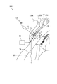
- FIG. 4 is a schematic cross-sectional view showing the implant 10 mounted on the eye 200.
- FIG. 5 is a partially enlarged view of FIG.
- the plate portion 3 is inserted between the sclera 201 and the Tenon's sac 203.
- a suture thread is inserted into the suture hole 34 (see FIG. 1) of the plate portion 3.
- the suture thread is inserted into the suture hole 34 to suture the plate portion 3 and the sclera 201.
- the plate portion 3 is fixed to the sclera 201.
- the presence of the plate portion 3 forms a bleb 204 around the plate portion 3 as a reaction of the human body.
- the bleb 204 also continues to be formed as the plate portion 3 continues to exist. As a result, the plate portion 3 floats in the bleb 204.
- the blebs 204 represent vesicles, small vesicles and / or small vesicles.
- the tube portion 1 extends toward the anterior chamber 202 along the sclera 201 from the plate portion 3. Then, the first end 1 a of the tube 1 penetrates the sclera 201 and is inserted into the anterior chamber 202.
- the target which the 1st end part 1a penetrates is not specifically limited.
- the tube 1 may penetrate the area 205 adjacent to the cornea 211 when inserted into the anterior chamber 202.
- this invention is not limited to this.
- the first end 1a of the tube 1 may be inserted into the flat ciliary body.
- the second opening 13 of the tube 1 is disposed between the sclera 201 and the Tenon's capsule 203.
- the tube portion 1 has a predetermined portion 14.
- the predetermined portion 14 is located between the first opening 12 and the second opening 13 in the pipe portion 1. Further, in a state where the implant 10 is attached to the eye 200, the predetermined portion 14 is disposed between the sclera 201 of the eye 200 and the conjunctiva 206 of the eye 200. Note that Tenon's sac 203 is disposed between the sclera 201 and the conjunctiva 206. When the predetermined portion 14 is disposed between the sclera 201 and the conjunctiva 206 with the implant 10 attached to the eye 200, the position of the predetermined portion 14 with respect to the tenon capsule 203 is not particularly limited.
- the predetermined portion 14 may be disposed between the sclera 201 and the conjunctiva 206.
- the predetermined portion 14 may be disposed below the tenon capsule 203.
- the sclera 201, the predetermined portion 14, the tenon sac 203, and the conjunctiva 206 are disposed in the order of the sclera 201, the predetermined portion 14, the tenon sac 203, and the conjunctiva 206 from the sclera 201 toward the outside of the eye 200. Be done.
- the predetermined portion 14 may be disposed above the tenon capsule 203.
- the sclera 201, the predetermined portion 14, the tenon sac 203, and the conjunctiva 206 are disposed in the order of the sclera 201, the tenon sac 203, the predetermined portion 14, and the conjunctiva 206 from the sclera 201 toward the outside of the eye 200. Be done.
- the predetermined portion 14 is disposed below the Tenon's capsule 203.
- the flow path 11 contains the predetermined flow path 11a.
- the predetermined flow passage 11 a is located inside the predetermined portion 14 of the flow passage 11.
- the plurality of throttles 2 are disposed in the predetermined flow path 11a.
- the first opening 12 of the tube 1 is disposed inside the anterior chamber 202.
- aqueous humor is produced by the ciliary body 207.
- the aqueous humor then circulates through the pupil to the anterior chamber 202 of the eye 200 in front of the crystalline lens 208 to provide nutrition.
- aqueous humor is drained out of the eye through trabecular meshwork 209, Schlemm's canal 210.
- clogging of the trabecular meshwork 209 prevents proper drainage of aqueous humor.
- the intraocular pressure rises beyond the normal range.
- the pressure causes the optic nerve to be damaged, resulting in impairment of visual field and visual acuity.
- bleb 204 When implant 10 is worn on eye 200, bleb 204 is formed.
- the aqueous humor in the anterior chamber 202 flows into the flow passage 11 through the first opening 12.
- the aqueous humor flowing into the flow channel 11 flows in the flow channel direction X through the flow channel 11 and is discharged from the second opening 13.
- the aqueous humor discharged from the second opening 13 is supplied into the bleb 204 and then permeates from the periphery of the bleb 204 into the living tissue. Therefore, the aqueous humor in the anterior chamber 202 is drained out of the eye via the flow path 11. As a result, it is possible to suppress an abnormal rise in intraocular pressure.
- the flow rate Z of the aqueous humor indicates, in detail, the amount of aqueous humor per unit time flowing out of the flow passage 11 through the second opening 13.
- a plurality of throttles 2 are disposed in the flow path 11.
- the area T of the hole 22 is smaller than the flow area U of the flow path 11 for each of the plurality of narrowed portions 2 (T ⁇ S). Therefore, each time the aqueous humor flowing in the flow passage 11 passes through the narrowed portion 2 (the hole 22), a pressure loss occurs in the aqueous humor.
- the number of the wall portions 21 disposed in the flow channel 11 increases, the chance of pressure loss with respect to the aqueous humor increases, and the flow rate Z of the aqueous humor decreases.
- each of the plurality of wall portions 21 can be removed from the flow path 11. Therefore, whenever the wall part 21 is removed from the flow path 11 and the number of the wall parts 21 arrange
- the plurality of throttles 2 are disposed in the flow channel 11. Ru. Therefore, when the operator removes any of the plurality of wall portions 21 from the flow channel 11, the number of the wall portions 21 to be removed and / or the holes 22 formed in the wall portions 21 to be removed Based on the area T, it is possible to predict how much the intraocular pressure will decrease after the removal of the wall 21. As a result, after the implant 10 is attached to the eye 200, it is possible to smoothly perform the operation of adjusting the intraocular pressure.
- the area T of the hole 22 is larger as the narrowed portion 2 is positioned downstream in the flow direction X among the plurality of narrowed portions 2. Therefore, the size of the area T of the plurality of holes 22 sequentially increases toward the downstream in the flow direction X, and changes regularly. As a result, it becomes easy to predict how much the intraocular pressure decreases after the removal of the wall 21.
- the size of the area T of the plurality of holes 22 regularly changes.
- the size of the area T of each of the plurality of holes 22 is not particularly limited, and the size of the area T of the plurality of holes 22 may not regularly change. Also, for example, the sizes of the areas T of the plurality of holes 22 may have the same size.
- each of the plurality of wall portions 21 is removed from the flow path 11 by being irradiated with the laser light L. Specifically, each of the plurality of wall portions 21 absorbs the laser light L when irradiated with the laser light L. As a result, heat is generated in each of the plurality of wall portions 21 and each of the plurality of wall portions 21 is burned off.
- the laser light L is, for example, a green laser, a yellow laser, or a red laser.
- the laser light L has a relatively long wavelength and a high depth of penetration.
- an irradiation unit 40 such as a multi-color laser photocoagulation device and a green laser photocoagulation device emits the laser light L.
- the operator operates the irradiation unit 40 while checking the position of each of the plurality of wall portions 21 using a microscope to irradiate each of the plurality of wall portions 21 with the laser light L.
- the tube portion 1 transmits the laser light L when it is irradiated with the laser light L.
- the tube portion 1 of the present embodiment transmits the laser light L by having a transparent color or a semitransparent color.
- at least a predetermined portion 14 of the tube portion 1 may transmit the laser light L.
- at least a predetermined portion 14 of the tubular portion 1 may be formed in a transparent color or a semitransparent color.
- Each of the plurality of wall portions 21 absorbs the laser light L when irradiated with the laser light L.
- each of the plurality of wall portions 21 has a color that can be visually recognized by a person through the pipe portion 1.
- each of the plurality of wall portions 21 has a dark color such as, for example, black or brown.
- the entire area of each of the plurality of wall portions 21 has a dark color such as black or brown.
- Each of the plurality of wall portions 21 is formed, for example, by coloring transparent or translucent silicone in a dark color. A person (operator) visually recognizes each of the plurality of wall portions 21 using a device such as a microscope.
- the laser beam L When the laser beam L is irradiated from the side of the tube portion 1 to the tube portion 1, the laser beam L passes through the tube portion 1. In detail, the laser beam L passes through the side of the tube portion 1. Then, the laser beam L transmitted through the tube portion 1 is absorbed by the targeted wall portion 21 among the plurality of wall portions 21. As a result, the targeted wall portion 21 is removed (burned away) from the flow path 11.
- the side of the pipe 1 indicates the side of the pipe 1 when the flow direction X is defined as the front-rear direction.
- the laser light L When the laser light L is irradiated from the side of the tube portion 1 to each of the plurality of wall portions 21 in a state in which the implant 10 is mounted to the eye 200, the laser light L becomes conjunctiva 206 and tenon's sac 203 And the pipe part 1. In this case, the laser beam L passes through the conjunctiva 206, the tenon capsule 203, and the tube 1 in the order of the conjunctiva 206, the tenon capsule 203, and the tube 1. Then, the laser beam L transmitted through the tube portion 1 is absorbed by each of the plurality of wall portions 21. As a result, each of the plurality of wall portions 21 is removed (burned away) from the flow path 11.
- the conjunctiva 206 and the tenon capsule 203 are translucent. Accordingly, the conjunctiva 206 and the tenon capsule 203 transmit high-penetration laser light L such as a green laser, a yellow laser, and a red laser, as in the tube 1 of the present embodiment.
- high-penetration laser light L such as a green laser, a yellow laser, and a red laser
- each of the plurality of wall portions 21 can be removed from the flow path 11. Therefore, after the implant 10 is attached to the eye 200, it is possible to remove one or more of the plurality of wall portions 21 from the flow channel 11 and adjust the intraocular pressure.
- the tube part 1 has a transparent color or a semi-transparent color.
- each of the plurality of wall portions 21 has a color that can be viewed through the pipe portion 1.
- each of the plurality of walls 21 can be seen through the tube 1.
- the operator can recognize the position of each of the plurality of wall portions 21 from the outside 1 c of the tube portion 1.
- the plurality of narrowed portions 2 are disposed in the predetermined flow path 11 a of the flow path 11. Therefore, with the implant 10 attached to the eye 200, the operator visually recognizes each of the plurality of wall portions 21 through the conjunctiva 206, the tenon sac 203, and the predetermined portion 14 of the tube 1 of the eye 200, It becomes possible to recognize the position of each of the plurality of wall portions 21. In the present embodiment, the operator visually recognizes each of the plurality of wall portions 21 using a microscope.
- each of the plurality of wall portions 21 irradiates the laser light L transmitted through the conjunctiva 206 of the eye 200, the tenon capsule 203, and the predetermined portion 14 of the tube 1 It is removed from the flow path 11 by being done. Therefore, with the implant 10 mounted on the eye 200, it is possible to remove each of the plurality of wall portions 21. As a result, the work of removing each of the plurality of wall portions 21 can be smoothly performed.
- each of the plurality of wall portions 21 is irradiated with the laser light L transmitted through the conjunctiva 206 of the eye 200 and the predetermined portion 14 of the tube portion 1. It is removed from the path 11.
- FIG. 6 is a flow chart showing a procedure for adjusting the intraocular pressure of the eye 200 to which the implant 10 is attached.
- the processes shown in steps S1 to S5 are performed using the implant system 100.
- the implant system 100 includes an implant 10, an irradiation unit 40, and a measurement unit 50 (see FIG. 5) that measures an intraocular pressure.
- step S1 the intraocular pressure of the eye 200 on which the implant 10 is mounted is measured.
- the operator uses the measuring unit 50 to measure the intraocular pressure of the eye 200 on which the implant 10 is mounted.
- the measuring unit 50 is, for example, a tonometer.
- the tonometer is, for example, a Goldman tonometer.
- step S2 it is determined whether the measured intraocular pressure is higher than a predetermined upper limit value.
- the predetermined upper limit indicates the upper limit of the range in which the intraocular pressure is normal.
- the predetermined upper limit is, for example, 21 mmHg which is generally the upper limit of normal intraocular pressure.
- the predetermined upper limit may be smaller than 21 mmHg.
- the predetermined upper limit may be 15 mmHg.
- the reason is that after the measurement of intraocular pressure, the intraocular pressure is adjusted before the intraocular pressure reaches 21 mmHg in consideration of the possibility that the intraocular pressure will gradually rise, and the normal intraocular pressure is made more sure. It is for securing.
- the intraocular pressure is higher than the predetermined upper limit (Yes in step S2), the process proceeds to step S3.
- the intraocular pressure is equal to or less than the predetermined upper limit (No in step S2), the process ends.
- step S 3 one of the plurality of wall portions 21 is removed from the flow path 11. Specifically, the wall portion 21 of the nth narrowed portion Cn is removed from the flow path 11. In this case, the operator operates the irradiation unit 40 to cause the irradiation unit 40 to irradiate the laser light L.
- the operator operates the irradiation unit 40 to cause the irradiation unit 40 to irradiate the laser light L.
- the irradiation unit 40 operates the irradiation unit 40 to cause the irradiation unit 40 to irradiate the laser light L.
- the wall portion 21 of the nth narrowed portion Cn is removed from the flow path 11.
- the wall portion 21 of the first narrowed portion C1 is removed from the flow passage 11.
- step S4 the intraocular pressure of the eye 200 equipped with the implant 10 is measured.
- step S5 it is determined whether the measured intraocular pressure is higher than a predetermined target value.
- the process proceeds to step S3.
- the wall portion 21 of the (n + 1) th narrowed portion C (n + 1) is removed from the flow passage 11 in step S3.
- the processes shown in steps S3 to S5 are repeated until it is determined in step S5 that the intraocular pressure is equal to or less than the predetermined target value.
- the intraocular pressure is equal to or less than the predetermined target value (No in step S5), the process ends.
- the predetermined target value is, for example, 10 mmHg.
- the predetermined target value may be 21 mmHg or less. However, it is preferable to set the predetermined target value to about 10 mmHg as in the present embodiment, in consideration of the possibility of the intraocular pressure rising gradually after the adjustment of the intraocular pressure is completed.
- steps S3 to S5 are repeated until it is determined that the intraocular pressure is equal to or less than the predetermined target value. Therefore, the flow rate Z of aqueous humor discharged by the pipe 1 (second opening 13) is gradually increased by removing the wall 21 one by one until the intraocular pressure becomes equal to or less than the predetermined target value. To reduce the pressure gradually. As a result, it is possible to suppress an abrupt change in intraocular pressure and perform the operation of adjusting the intraocular pressure in a stable state.
- the implant 10 can be worn not only to human eyes but also to eyes of non-human animals such as dogs.
- the method of adjusting the intraocular pressure of the eye to which the implant 10 is attached can be applied not only to humans but also to animals other than humans.
- the implant 10 includes the plurality of throttles 2.
- the implant 10 may comprise a single constriction 2. That is, the implant 10 comprises one or more constrictions 2. If the implant 10 comprises a single constriction 2, it is possible to make the implant 10 capable of adjusting the intraocular pressure compact.
- a plurality of implants 10 having different sizes of the area T of the hole 22 and / or the flow path area U of the flow path 11 are prepared, and the weight of the symptom of the glaucoma of the patient Depending on the height, the implant 10 to be attached to the eye of the patient may be selected from the plurality of implants 10.
- the implant 10 is used in which the area T of the hole 22 is larger and the flow area U of the flow path 11 is larger as the condition of the patient becomes heavier. As a result, it is possible to adjust the intraocular pressure effectively according to the weight of the patient's condition.
- the implant 10 of the present embodiment includes the tube portion 1, the plurality of narrowed portions 2, and the plate portion 3.
- the implant 10 may not be provided with the plate portion 3, and may be provided with at least the tube portion 1 and the single or plural constricted portions 2. That is, the implant 10 forms the flow path 11 inside the tube portion 1, arranges the plurality of narrowed portions 2 in the flow path 11, and generates the aqueous humor generated by the eye 200 through the flow path 11 to the outside of the eye 200 It should just have the function to guide to.
- the implant 10 when the implant 10 is attached to the eye 200, for example, the implant 10 includes the following (i) to (i) It will be in the state shown in iii).
- the first end 1a of the tube 1 is inserted into the anterior chamber 202 (see FIG. 4).
- the predetermined portion 14 of the tube portion 1 is disposed between the sclera 201 and the conjunctiva 206.
- the second end 1 b of the tube 1 is fixed directly or indirectly to the rear of the sclera 201.
- the posterior part of the sclera 201 shows the part of the sclera 201 located behind the conjunctiva 206 and behind the eye 200.
- the implant 10 can be simply configured without using the plate portion 3.
- the tube 1 of the present embodiment is arranged to extend from the anterior chamber 202 to the back of the eye 200.
- the arrangement place of the tube portion 1 is not particularly limited.
- the tube portion 1 may be disposed at a position where aqueous humor can be guided to the outside of the eye 200 through the flow path 11.
- FIG. 7 is a cross-sectional view showing a modified example of the wall portion 21.
- Each of the plurality of wall portions 21 in the present embodiment is disposed substantially parallel to the vertical direction Y (see FIG. 3B).
- the vertical direction Y indicates a direction perpendicular to the flow direction X.
- the present invention is not limited to this.
- at least one of the plurality of wall portions 21 may be inclined with respect to the vertical direction Y.
- the fact that the wall portion 21 is inclined with respect to the vertical direction Y indicates that the inclination angle ⁇ ° of the wall surface 21 a of the wall portion 21 with respect to the vertical direction Y is not 0 ° ( ⁇ ⁇ 0 °).
- the inclination angle ⁇ ° is preferably an acute angle. That is, it is preferable that the lower end 21 b of the wall 21 be positioned upstream of the upper end 21 c of the wall 21 in the flow direction X.
- the inclination angle ⁇ ° is an acute angle
- the implant 10 is viewed from the front side (front side) of the eye 200 with the implant 10 attached to the eye 200, the line of sight G to the implant 10 faces the wall 21a of the wall 21 Do.
- step S3 Although one wall 21 is removed in step S3 shown in FIG. 6, the present invention is not limited to this.
- two or more wall portions 21 may be removed in step S3. That is, the number of wall portions 21 to be removed in step S3 is changed according to the height of the intraocular pressure measured in step S1.
- the number of wall portions 21 to be removed is determined by the operator. The number of wall portions 21 to be removed in step S3 may be determined, for example, based on the rule of thumb of the operator.
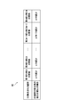
- FIG. 8 is a diagram showing the change information 80. As shown in FIG. 8
- the number of wall portions 21 to be removed in step S3 shown in FIG. 6 is determined based on the change information 80, for example.
- the change information 80 associates the wall portion 21 removed from the flow path 11 among the plurality of wall portions 21 with the intraocular pressure after removal of the wall portion 21 for each wall portion 21 (A). It is information.
- the intraocular pressure after removal of the wall 21 is the value of intraocular pressure after removal of the wall 21, the change in intraocular pressure after removal of the wall 21, or the value after removal of the wall 21. Indicates the rate of change in intraocular pressure.
- the intraocular pressure after removal of the wall 21 indicates the rate of change in intraocular pressure after removal of the wall 21.
- the change information 80 is acquired by performing an experiment in advance.
- Each value of the intraocular pressure after removal of the wall 21, the change in intraocular pressure after removal of the wall 21, and the rate of change in intraocular pressure after removal of the wall 21 are each a constant value as well. It may be a value having a width having an upper limit and a lower limit such as D or more and E or less. D and E are real numbers.
- a procedure for adjusting the intraocular pressure using the change information 80 will be described.
- the operator confirms the change information 80 when confirming the intraocular pressure measured in step S1. Then, the operator selects, based on the change information 80, one or more wall portions 21 which can be removed to reduce the intraocular pressure to a predetermined target value or less. Then, the operator operates the irradiation unit 40 to irradiate the laser light L to the wall 21 selected by the operator. As a result, the wall 21 selected by the operator is removed from the flow path 11.
- a storage unit that stores change information 80 and / or a sheet on which an image indicating change information 80 is formed is included in implant system 100.
- the storage unit may be any one as long as the operator can access the change information 80 stored in the storage unit.
- the storage unit is, for example, a USB memory.
- the sheet is, for example, paper.
- step S1 As mentioned above, according to the magnitude
- the area T of the hole 22 is larger as the narrowed portion 2 is positioned downstream in the flow direction X.
- the present invention is not limited to this.
- the size of the area T of the plurality of holes 22 is not particularly limited. However, if the size of the area T of the plurality of holes 22 regularly changes as in the present embodiment, it becomes easy to predict the amount of change in intraocular pressure when the wall 21 is removed.
- step S3 to step S5 when the processes shown in step S3 to step S5 are repeated, they are removed in order from the wall portion 21 of the first narrowed portion C1.
- the present invention is not limited to this.
- the order in which the wall portions 21 of the first narrowed portion C1 to the Nth narrowed portion CN are removed is not particularly limited.
- the wall portion 21 to be removed may be determined among the plurality of wall portions 21 based on the change information 80 of the above (5).
- the invention is applicable to the field of implants used for the treatment of the eye.
Landscapes
- Health & Medical Sciences (AREA)
- Ophthalmology & Optometry (AREA)
- Life Sciences & Earth Sciences (AREA)
- Heart & Thoracic Surgery (AREA)
- Public Health (AREA)
- Surgery (AREA)
- Engineering & Computer Science (AREA)
- Biomedical Technology (AREA)
- Veterinary Medicine (AREA)
- General Health & Medical Sciences (AREA)
- Animal Behavior & Ethology (AREA)
- Vascular Medicine (AREA)
- Nuclear Medicine, Radiotherapy & Molecular Imaging (AREA)
- Physics & Mathematics (AREA)
- Optics & Photonics (AREA)
- Biophysics (AREA)
- Medical Informatics (AREA)
- Molecular Biology (AREA)
- Prostheses (AREA)
Abstract
インプラント(10)は、眼(200)に装着可能である。インプラント(10)は、管部(1)と、絞り部(2)とを備える。管部(1)の内部には、房水の流路(11)が形成される。絞り部(2)は、流路(11)に配置される。管部(1)には、第1開口部(12)と、第2開口部(13)とが形成される。第1開口部(12)は、流路(11)と管部(1)の外部(1c)とを連通する。第2開口部(13)は、流路(11)と管部(1)の外部(1c)とを連通する。絞り部(2)は、流路(11)に配置される壁部(21)と、壁部(21)を貫通する孔部(22)とを含む。
Description
本発明は、インプラント、及びインプラントシステムに関する。
特許文献1に記載のインプラントは、プレートと、排出管とを備える。プレートは、強膜に縫合される。排出管は、プレートと前房との間に配置される。インプラントが眼に装着されると、前房内の房水が、排出管を通じてプレートへ排出される。その結果、眼圧の異常な上昇を抑えることが可能になる。
しかし、プレートへ排出される房水の量が少なすぎると、房水が前房から眼外に十分に排出されず、眼圧を目標とする大きさまで低下させることが困難になる。
一般に、インプラントを眼に装着する際、排出管を締付糸で縛っていた。そして、締付糸が排出管を締め付ける締付力の強さに応じて、インプラントによる房水の排出量が調整されていた。詳細には、締付力が大きくなるほど、インプラントによる房水の排出量が減少する。また、インプラントが眼に装着された後、インプラントによる房水の排出量が減少し、眼圧が所望の大きさまで低下しないことがあった。この場合、締付糸を、術者がレーザー光でカットしていた。締付糸がカットされると、カットされた締付糸の締付力から排出管が解放され、インプラントによる房水の排出量が増加していた。その結果、眼圧が低下していた。
しかし、術者が締付糸をカットする際、カットする締付糸の締付力の強さを認識することは困難であった。従って、術者は、締付糸をカットすることで、インプラントによる房水の排出量がどの程度増加し、眼圧がどの程度低下するかを予測することが困難であった。その結果、術者は、眼圧の低下の程度を予測することなく、締付糸をカットしており、眼圧を調整する作業を円滑に行うことが困難であった。
本発明は、上記課題に鑑みてなされたものであり、インプラントが眼に装着された後、眼圧を調整する作業を円滑に行うことが可能なインプラント、及びインプラントシステムを提供することを目的としている。
本願に開示するインプラントは、眼に装着可能である。インプラントは、管部と、絞り部とを備える。管部の内部には、房水の流路が形成される。絞り部は、前記流路に配置される。前記管部には、第1開口部と、第2開口部とが形成される。第1開口部は、前記流路と前記管部の外部とを連通する。第2開口部は、前記流路と前記管部の外部とを連通する。前記複数の絞り部の各々は、前記流路に配置される壁部と、前記壁部を貫通する孔部とを含む。
本願に開示するインプラントにおいて、前記壁部は、前記流路から除去可能であることが好ましい。
本願に開示するインプラントにおいて、前記壁部は、レーザー光を照射されることで前記流路から除去されることが好ましい。
本願に開示するインプラントにおいて、前記管部は、前記レーザー光を透過することが好ましい。前記壁部は、前記レーザー光を吸収することが好ましい。
本願に開示するインプラントにおいて、前記管部は、透明の色又は半透明の色を有することが好ましい。前記壁部は、前記管部を介して視認可能な色を有することが好ましい。
本願に開示するインプラントにおいて、前記インプラントが前記眼に装着された状態で、前記管部は、前記眼の強膜と前記眼の結膜との間に配置される所定部分を含むことが好ましい。前記流路は、前記管部の所定部分の内部に位置する所定流路を含むことが好ましい。前記絞り部は、前記所定流路に配置されることが好ましい。
本願に開示するインプラントにおいて、前記インプラントが前記眼に装着された状態で、前記複数の壁部の各々は、前記眼の結膜、及び前記眼のテノン嚢、並びに前記管部の所定部分を透過する前記レーザー光、又は、前記眼の結膜、並びに前記管部の所定部分を透過する前記レーザー光を照射されることで前記流路から除去されることが好ましい。
本願に開示するインプラントにおいて、前記壁部は、流路方向に対して垂直な方向である垂直方向に対して傾斜することが好ましい。前記流路方向は、前記第1開口部から前記流路を通じて前記第2開口部に向かう方向を示すことが好ましい。
本願に開示するインプラントにおいて、前記流路には、複数の前記絞り部が配置されることが好ましい。前記複数の絞り部は、流路方向に沿って並ぶことが好ましい。前記流路方向は、前記第1開口部から前記流路を通じて前記第2開口部に向かう方向を示すことが好ましい。前記複数の絞り部のうち、前記流路方向の下流に位置する絞り部ほど、前記孔部の面積が大きいことが好ましい。
本願に開示するインプラントシステムは、上記インプラントと、照射部と、計測部とを備える。照射部は、レーザー光を照射する。計測部は、眼圧を計測する。
本発明によれば、インプラントが眼に装着された後、眼圧を調整する作業を円滑に行うことができる。
本発明の実施形態について、図面を参照しながら説明する。なお、図中、同一又は相当部分については同一の参照符号を付して説明を繰り返さない。
図1、及び図2を参照して、本発明の実施形態であるインプラント10について説明する。図1は、インプラント10の斜視図である。図2は、図1のII-II断面図である。
図1、及び図2に示すように、インプラント10は、緑内障の治療に用いられる。インプラント10は、眼に装着可能である。インプラント10が眼に装着されると、眼から房水が流出することをインプラント10が促進させる。その結果、眼圧の異常な上昇を抑えることが可能になる。
インプラント10は、管部1と、絞り部2と、板部3とを含む。
管部1は、管状の形状を有する。つまり、管部1は、中空の形状を有する。管部1は、柔軟性、可撓性、及び/又は、弾性を有する。管部1は、例えば、シリコーン、エラストマー樹脂、又は、弾性を有する樹脂材料で形成される。本実施形態の管部1は、シリコーン製のチューブである。
管部1は、第1端部1aと、第2端部1bとを有する。管部1は、第1端部1aから第2端部1bに向かって延びる長手の形状を有する。
絞り部2は、管部1の内部に配置される。
板部3は、プレート状の形状を有する。板部3の平面視形状は、例えば、円形状、楕円形状、又は、角部が曲線となった四角形状である。
板部3は、主表面31と、本体部32とを有する。板部3の主表面31は、本体部32に形成される。板部3の主表面31の面積は、例えば、100平方ミリメートル以上600平方ミリメートル以下である。板部3の主表面31は、眼球の表面に沿った曲面形状を有する。板部3の主表面31の曲率半径は例えば12ミリメートル以上14ミリメートル以下である。板部3の厚さは、例えば、0.5ミリメートル以上2ミリメートル以下である。
板部3は、例えば、柔軟性、可撓性、又は、弾性を有する材料により形成される。具体的には、板部3は、例えば、シリコンエラストマーを含む材料により形成される。その結果、インプラント10が眼に装着された状態で、眼球の表面に沿った曲面形状に板部3を変形させることが可能になる。
板部3には、管部1が固定される。詳細には、板部3には、管部1の第2端部1bが固定される。管部1の第2端部1bは、板部3(本体部32)の上部に配置される。これに対し、管部1の第1端部1aは、板部3の外方に位置する。
板部3は、膨出部33と、縫合孔34と、凸部35と、複数の貫通孔36と、挿通孔37とをさらに有する。膨出部33は、本体部32から膨出する。縫合孔34は、膨出部33に形成される。縫合孔34は、膨出部33を貫通する。
凸部35は、本体部32から上方に突出する形状を有する。凸部35と本体部32との間には、挿通孔37が形成される。挿通孔37には、管部1が挿通される。管部1は、挿通孔37に挿通された状態で、本体部32に固定される。詳細には、管部1の第2端部1bは、挿通孔37に挿通された状態で、本体部32に固定される。
複数の貫通孔36の各々は、板部3を貫通する。詳細には、複数の貫通孔36の各々は、板部3の本体部32を貫通する。
次に、図3(a)、及び図3(b)を参照して、管部1と絞り部2とについて説明する。図3(a)は、管部1の斜視図である。図3(b)は、管部1の断面図である。
図3(a)、及び図3(b)に示すように、管部1の内部には、房水の流路11が形成される。流路11は、管部1の内面で囲まれた空間を示す。管部1は、眼で生成された房水を、流路11を通じて眼の外部に案内する。また、管部1には、第1開口部12と、第2開口部13とが形成される。管部1の両端部は、第1開口部12と第2開口部13とによって開放されている。第1開口部12は、第1端部1aに形成される。第1開口部12は、流路11と管部1の外部1cとを連通する。第2開口部13は、第2端部1bに形成される。第2開口部13は、流路11と管部1の外部1cとを連通する。管部1は、第1開口部12を介して流路11に流入した房水を、第2開口部13を介して流路11から排出する。
絞り部2は、流路11に配置される。絞り部2は、流路11の流路面積Uを絞ることで、流路11(第2開口部13)から排出される房水の単位時間当たりの量を調整する。流路面積Uは、流路方向Xに対して垂直な方向に流路11を切断したときの、流路11の断面積を示す。また、流路方向Xは、第1開口部12から流路11を通じて第2開口部13に向かう方向を示す。つまり、流路方向Xは、管部1の延びる方向を示す。
絞り部2は、壁部21と、孔部22とを含む。壁部21は、板形状を有する。壁部21は、流路11に配置される。つまり、流路11のうち、壁部21の上流と、壁部21の下流との連通は、壁部21により妨げられる。なお、壁部21の上流は、詳細には、壁部21に対する流路方向Xの上流を示す。また、壁部21の下流は、詳細には、壁部21に対する流路方向Xの下流を示す。
壁部21は、例えば、管部1と同一の材料で形成される。なお、壁部21が、管部1とは異なる材料で形成されてもよい。壁部21は、流路11に固定され、又は、流路11と一体形成される。つまり、壁部21は、管部1と一体でもよく、管部1と別体でもよい。
壁部21には、孔部22が形成される。孔部22は、壁部21を貫通する。詳細には、孔部22は、流路方向Xに沿って壁部21を貫通する。従って、流路11のうち、壁部21の上流と、壁部21の下流とは、孔部22を介して連通する。つまり、壁部21の位置する場所では、孔部22が流路11を形成する。なお、孔部22には、図3(a)及び図3(b)に示すような孔部22のみならず、管部1の内面と壁部21との間に形成される隙間も含まれる。つまり、壁部21を流路11よりも小さく形成し、壁部21を流路11に配置したときに、管部1の内面と壁部21との間に孔部22である隙間が形成されるように構成してもよい。管部1が円筒形状を有する場合、管部1の内径(流路11の径)は、例えば、0.5mm程度の寸法を有する。また、孔部22の断面の形状が円形状を有する場合、孔部22の径は、例えば、0.1mm~0.3mm程度の寸法を有する。孔部22の断面は、流路方向Xに対して垂直な断面を示す。なお、管部1は、流路11を通じて房水を案内可能な形状を有していればよい。従って、管部1の形状は、円筒形状に限定されない。また、孔部22は、房水が通過可能な形状を有していればよい。従って、孔部22の断面の形状は、円形状に限定されない。
流路11には、複数の絞り部2が配置される。本実施形態では、N個の絞り部2が配置される。Nは、2以上の整数である。複数の絞り部2は、流路方向Xに沿って並ぶ。複数の絞り部2のうち、流路方向Xの最上流に位置する絞り部2から数えて、n番目に位置する絞り部2を、第n絞り部Cnと記載する。nは、N以下の整数である。従って、例えば、1番目の絞り部2は第1絞り部C1と記載され、2番目の絞り部2は第2絞り部C2と記載される。なお、図1、図4、及び図5では、複数の絞り部2の一例として、4個の絞り部2が図示される(N=4)。
複数の絞り部2の各々について、孔部22の面積Tは、流路11の流路面積Uよりも小さい(T<U)。孔部22の面積Tは、孔部22の縁部22aで囲まれた領域の面積を示す。言い換えれば、孔部22の面積Tは、孔部22を閉塞させるために必要な領域の面積を示す。
複数の絞り部2のうち、第n絞り部Cnの孔部22の面積Tを、面積Tnと記載する。従って、例えば、1番目の第1絞り部C1の孔部22の面積Tは面積T1と記載され、2番目の第2絞り部C2の孔部22の面積Tは面積T2と記載される。
複数の絞り部2のうち、流路方向Xの下流に位置する絞り部2ほど、孔部22の面積Tが大きい。つまり、第(n-1)絞り部C(n-1)の孔部22の面積T(n-1)よりも、第n絞り部Cnの孔部22の面積Tnの方が大きい(T(n-1)<Tn)。
本実施形態では、流路11は、例えば、約0.5mmの内径を有する。また、第1絞り部C1の孔部22は、例えば、約0.1mmの内径を有する。また、第2絞り部C2の孔部22は、例えば、約0.3mmの内径を有する。
次に、図4、及び図5を参照して、インプラント10が眼200に装着されたときの、板部3の位置について説明する。図4は、眼200に装着された状態のインプラント10を示す模式的断面図である。図5は、図4の一部拡大図である。
図4、及び図5に示すように、板部3は、強膜201とテノン嚢203との間に挿入される。板部3の縫合孔34(図1参照)には、縫合糸が挿通される。縫合糸は、縫合孔34に挿通されて、板部3と強膜201とを縫合する。その結果、板部3が強膜201に固定される。
板部3が強膜201に固定された後に、ある程度の期間が経過すると、眼内の生体組織が成長する。そして、眼内の生体組織が複数の貫通孔36(図1参照)の各々を通ってテノン嚢203と強膜201との間を連結する。その結果、眼内での板部3の位置がずれることが抑制され、眼内での板部3の位置が安定する。
板部3が存在することにより、人体の反応として板部3の周囲にブレブ204が形成される。板部3が存在し続けることによりブレブ204も形成され続ける。その結果、板部3はブレブ204内で浮遊する。ブレブ204は、小胞、小水胞、及び/又は、小気胞を示す。
続いて、図4、及び図5を参照して、インプラント10が眼200に装着されたときの、管部1の位置について説明する。
図4、及び図5に示すように、管部1は、板部3から強膜201に沿いつつ、前房202側に向かって延びる。そして、管部1の第1端部1aは、強膜201を貫通して、前房202内に挿入される。なお、管部1の第1端部1aが、前房202内に挿入される際、第1端部1aの貫通する対象は特に限定されない。例えば、管部1は、前房202内に挿入される際、角膜211に隣接する領域205を貫通してもよい。また、本実施形態では、管部1の第1端部1aは、前房202内に挿入されたが、本発明はこれに限定されない。管部1の第1端部1aは、例えば、毛様体扁平部に挿入されてもよい。
インプラント10が眼200に装着された状態で、管部1の第2開口部13は、強膜201とテノン嚢203との間に配置される。
管部1は、所定部分14を有する。所定部分14は、管部1のうち、第1開口部12と第2開口部13との間に位置する。また、インプラント10が眼200に装着された状態で、所定部分14は、眼200の強膜201と、眼200の結膜206との間に配置される。なお、強膜201と、結膜206との間には、テノン嚢203が配置される。インプラント10が眼200に装着された状態で、所定部分14が、強膜201と、結膜206との間に配置されるとき、テノン嚢203に対する所定部分14の位置は特に限定されない。所定部分14は、強膜201と、結膜206との間に配置されればよい。例えば、インプラント10が眼200に装着された状態で、所定部分14が、テノン嚢203の下方に配置されてもよい。この場合、強膜201、所定部分14、テノン嚢203、及び結膜206は、強膜201から眼200の外側に向かって、強膜201、所定部分14、テノン嚢203、及び結膜206の順に配置される。また、インプラント10が眼200に装着された状態で、所定部分14が、テノン嚢203の上方に配置されてもよい。この場合、強膜201、所定部分14、テノン嚢203、及び結膜206は、強膜201から眼200の外側に向かって、強膜201、テノン嚢203、所定部分14、及び結膜206の順に配置される。本実施形態では、所定部分14は、テノン嚢203の下方に配置される。
また、流路11は、所定流路11aを含む。所定流路11aは、流路11のうち、所定部分14の内部に位置する。本実施形態では、複数の絞り部2は、所定流路11aに配置される。
インプラント10が眼200に装着された状態で、管部1の第1開口部12は、前房202の内部に配置される。
続いて、図4、及び図5を参照して、インプラント10の機能について説明する。
図4、及び図5に示すように、房水は毛様体207によって生成される。そして、房水は、水晶体208の前方において、瞳孔を通じて眼200の前房202へと循環して栄養を供給する。正常な眼200では、房水は線維柱帯209、シュレム管210を通じて眼球外へと排出される。しかし、緑内障の患者の場合、例えば、線維柱帯209の詰まりによって房水の適切な排出が妨げられる。その結果、眼圧が正常な範囲を超えて上昇する。また、眼圧が異常に上昇すると、例えば、圧力により視神経がダメージを受けて視野や視力に障害が発生する。
インプラント10が眼200に装着されると、ブレブ204が形成される。また、前房202内の房水は、第1開口部12を介して流路11に流入する。そして、流路11に流入した房水は、流路11を通じて流路方向Xに流れ、第2開口部13から排出される。そして、第2開口部13から排出された房水は、ブレブ204内に供給された後に、ブレブ204の周囲から生体組織内に浸透していく。従って、前房202内の房水が流路11を介して眼外に排出される。その結果、眼圧の異常な上昇を抑制することが可能になる。
次に、図3(a)、図3(b)、及び図5を参照して、房水の流量Zと、流路11に配置される壁部21の個数との関係について説明する。房水の流量Zは、詳細には、流路11から第2開口部13を介して流出する単位時間当たりの房水の量を示す。
図3(a)、図3(b)、及び図5に示すように、流路11には、複数の絞り部2が配置される。また、複数の絞り部2の各々について、孔部22の面積Tは、流路11の流路面積Uよりも小さい(T<S)。従って、流路11を流れる房水が絞り部2(孔部22)を通過する毎に、房水に圧力損失が生じる。その結果、流路11に配置される壁部21の個数が多くなるほど、房水に対して圧力損失の生じる機会が増加し、房水の流量Zが少なくなる。
また、複数の壁部21の各々は、流路11から除去可能である。従って、流路11から壁部21が除去され、流路11に配置される壁部21の個数が減少する毎に、房水に対して圧力損失の生じる機会が低減する。その結果、流路11に配置される壁部21の個数が減少する毎に、房水の流量Zが多くなる。
なお、孔部22の面積Tが小さいほど、圧力損失の程度が大きくなる。従って、孔部22の面積Tが小さいほど、房水の流量Zが少なくなる。
以上、図3(a)、図3(b)、及び図5を参照して説明したように、流路11には、複数の絞り部2(壁部21、及び孔部22)が配置される。従って、術者は、複数の壁部21のうちのいずれかを流路11から除去する場合、除去する壁部21の個数、及び/又は、除去する壁部21に形成された孔部22の面積Tに基づいて、壁部21の除去後に眼圧がどの程度低下するかを予測することが可能である。その結果、インプラント10が眼200に装着された後、眼圧を調整する作業を円滑に行うことが可能になる。
また、複数の絞り部2のうち、流路方向Xの下流に位置する絞り部2ほど、孔部22の面積Tが大きい。従って、複数の孔部22の面積Tの大きさが、流路方向Xの下流に向かって順番に大きくなり、規則的に変化する。その結果、壁部21の除去後に眼圧がどの程度低下するかを予測することが容易になる。なお、本実施形態では、複数の孔部22の面積Tの大きさが規則的に変化する。しかし、複数の孔部22の各々の面積Tの大きさは特に限定されず、複数の孔部22の面積Tの大きさが規則的に変化しなくてもよい。また、例えば、複数の孔部22の面積Tの大きさが互いに同じ大きさを有していてもよい。
次に、図5を参照して、流路11に配置される複数の壁部21の各々を除去するための構成について説明する。
図5に示すように、本実施形態では、複数の壁部21の各々は、レーザー光Lを照射されることで流路11から除去される。具体的には、複数の壁部21の各々は、レーザー光Lを照射されると、レーザー光Lを吸収する。その結果、複数の壁部21の各々に熱が発生し、複数の壁部21の各々が焼失する。
レーザー光Lは、例えば、緑色レーザー、黄色レーザー、又は、赤色レーザーである。レーザー光Lは、比較的波長が長く、深達度が高い。例えば、マルチカラーレーザー光凝固装置、及びグリーンレーザー光凝固装置のような照射部40が、レーザー光Lを照射する。また、術者が、顕微鏡を用いて複数の壁部21の各々の位置を確認しながら、照射部40を操作して、複数の壁部21の各々に対するレーザー光Lの照射を行う。
管部1は、レーザー光Lを照射されると、レーザー光Lを透過する。具体的には、本実施形態の管部1は、透明の色、又は、半透明の色を有することにより、レーザー光Lを透過する。なお、管部1のうち、少なくとも、所定部分14がレーザー光Lを透過すればよい。具体的には、管部1のうち、少なくとも、所定部分14が透明の色、又は、半透明の色に形成されていればよい。
複数の壁部21の各々は、レーザー光Lを照射されると、レーザー光Lを吸収する。また、複数の壁部21の各々は、管部1を介して人が視認可能な色を有する。具体的には、複数の壁部21の各々は、例えば、黒色、又は、茶色のような濃い色を有する。本実施形態では、複数の壁部21の各々の全域が、黒色、又は、茶色のような濃い色を有する。複数の壁部21の各々は、例えば、透明、又は、半透明のシリコーンを、濃い色に着色して形成される。なお、人(術者)は、顕微鏡のような装置を用いて複数の壁部21の各々を視認する。
管部1に対して管部1の側方から、レーザー光Lが照射されると、レーザー光Lが管部1を透過する。詳細には、レーザー光Lが管部1の側部を透過する。そして、管部1を透過したレーザー光Lは、複数の壁部21のうち狙った壁部21に吸収される。その結果、狙った壁部21が、流路11から除去(焼失)される。なお、管部1の側方は、流路方向Xを前後方向と規定したときの管部1の側方を示す。
インプラント10が眼200に装着された状態で、複数の壁部21の各々に対して、管部1の側方からレーザー光Lが照射されると、レーザー光Lが、結膜206、テノン嚢203、及び管部1を透過する。この場合、レーザー光Lは、結膜206、テノン嚢203、及び管部1の順に、結膜206、テノン嚢203、及び管部1を透過する。そして、管部1を透過したレーザー光Lは、複数の壁部21の各々に吸収される。その結果、複数の壁部21の各々が、流路11から除去(焼失)される。なお、結膜206、及びテノン嚢203は、半透明である。従って、結膜206、及びテノン嚢203は、本実施形態の管部1と同様に、緑色レーザー、黄色レーザー、及び、赤色レーザーのような深達度の高いレーザー光Lを透過する。
以上、複数の壁部21の各々は、流路11から除去可能である。従って、インプラント10が眼200に装着された後、流路11から複数の壁部21のうちの1つ、又は2つ以上を除去し、眼圧を調整することが可能になる。
また、管部1は、透明の色又は半透明の色を有する。また、複数の壁部21の各々は、管部1を介して視認可能な色を有する。従って、複数の壁部21の各々は、管部1を介して透けて見える。その結果、術者は、管部1の外部1cから、複数の壁部21の各々の位置を認識することが可能になる。
また、複数の絞り部2(壁部21、及び孔部22)は、流路11のうち、所定流路11aに配置される。従って、インプラント10が眼200に装着された状態で、術者は、眼200の結膜206、テノン嚢203、及び管部1の所定部分14を介して複数の壁部21の各々を視認し、複数の壁部21の各々の位置を認識することが可能になる。なお、本実施形態では、術者は、顕微鏡を用いて複数の壁部21の各々を視認する。
また、インプラント10が眼200に装着された状態で、複数の壁部21の各々は、眼200の結膜206、及びテノン嚢203、並びに管部1の所定部分14を透過するレーザー光Lを照射されることで流路11から除去される。従って、インプラント10が眼200に装着された状態で、複数の壁部21の各々を除去することが可能になる。その結果、複数の壁部21の各々を除去する作業を円滑に行うことが可能になる。なお、インプラント10が眼200に装着された状態で、所定部分14が、テノン嚢203の上方に配置される場合、レーザー光Lは、結膜206及び管部1を透過するが、テノン嚢203を透過することなく、複数の壁部21の各々に吸収される。従って、インプラント10が眼200に装着された状態で、複数の壁部21の各々は、眼200の結膜206、並びに管部1の所定部分14を透過するレーザー光Lを照射されることで流路11から除去される。
次に、図6を参照して、インプラント10が装着された眼200の眼圧を調整する手順(ステップS1~ステップS5)について説明する。詳細には、眼200にインプラント10を装着する緑内障手術が行われた後に、眼圧を調整する手順について説明する。図6は、インプラント10が装着された眼200の眼圧を調整する手順を示すフローチャートである。なお、ステップS1~ステップS5に示す処理は、インプラントシステム100を用いて行われる。インプラントシステム100は、インプラント10と、照射部40と、眼圧を計測する計測部50(図5参照)とを備える。
図6に示すように、ステップS1において、インプラント10が装着された眼200の眼圧を計測する。詳細には、術者は、計測部50を用いて、インプラント10が装着された眼200の眼圧を計測する。計測部50、例えば、眼圧計である。眼圧計は、例えば、ゴールドマン眼圧計である。
ステップS2において、計測した眼圧が所定の上限値より高いか否かを判定する。所定の上限値は、眼圧が正常とされる範囲の上限を示す。所定の上限値は、例えば、一般に正常な眼圧の上限とされる21mmHgである。なお、所定の上限値は、21mmHgより小さくてもよい。例えば、所定の上限値を、15mmHgとしてもよい。理由は、眼圧の計測時以降、眼圧が徐々に上昇する可能性を考慮して、眼圧が21mmHgに到達するよりも前に眼圧の調整を行い、正常な眼圧をより確実に確保するためである。眼圧が所定の上限値より高いとき(ステップS2で、Yes)、処理がステップS3に移行する。これに対し、眼圧が所定の上限値以下のとき(ステップS2で、No)、処理が終了する。
ステップS3において、複数の壁部21のうちの1つを、流路11から除去する。具体的には、第n絞り部Cnの壁部21を、流路11から除去する。この場合、術者は、照射部40を操作し、照射部40からレーザー光Lを照射させる。詳細には、インプラント10が眼200に装着された状態で、眼200の結膜206、及びテノン嚢203、並びに管部1(所定部分14)を介して、第n絞り部Cnの壁部21にレーザー光Lが照射される。その結果、第n絞り部Cnの壁部21が流路11から除去される。なお、本実施形態では、まず、第1絞り部C1の壁部21が流路11から除去される。
ステップS4において、インプラント10が装着された眼200の眼圧を計測する。
ステップS5において、計測した眼圧が所定の目標値より高いか否かを判定する。眼圧が所定の目標値より高いとき(ステップS5で、Yes)、処理がステップS3に移行する。この場合、ステップS3において、第(n+1)絞り部C(n+1)の壁部21が流路11から除去される。そして、ステップS5において、眼圧が所定の目標値以下と判定されるまで、ステップS3~ステップS5に示す処理が繰り返される。これに対し、眼圧が所定の目標値以下のとき(ステップS5で、No)、処理が終了する。所定の目標値は、例えば、10mmHgである。なお、所定の目標値は、21mmHg以下であればよい。しかし、眼圧の調整が終了した後、眼圧が徐々に上昇する可能性を考慮すると、所定の目標値を、本実施形態のように、10mmHg程度に設定することが好ましい。
以上、図6を参照して説明したように、眼圧が所定の目標値以下と判定されるまで、ステップS3~ステップS5に示す処理が繰り返される。従って、眼圧が所定の目標値以下になるまで、壁部21を1つずつ除去していくことで、管部1(第2開口部13)が排出する房水の流量Zを徐々に増加させ、眼圧を徐々に下げることができる。その結果、眼圧の急激な変動を抑制し、眼圧を調整する作業を安定した状態で行うことができる。
以上、図面(図1~図6)を参照しながら本発明の実施形態について説明した。但し、本発明は、上記の実施形態に限られるものではなく、その要旨を逸脱しない範囲で種々の態様において実施することが可能である(例えば、(1)~(8))。また、上記の実施形態に開示されている複数の構成要素を適宜組み合わせることによって、種々の発明の形成が可能である。例えば、実施形態に示される全構成要素から幾つかの構成要素を削除してもよい。図面は、理解しやすくするために、それぞれの構成要素を主体に模式的に示しており、図示された各構成要素の個数等は、図面作成の都合から実際とは異なる場合もある。また、上記の実施形態で示す各構成要素は一例であって、特に限定されるものではなく、本発明の効果から実質的に逸脱しない範囲で種々の変更が可能である。
(1)インプラント10は、人間の眼のみならず、例えば、犬のような人間以外の動物の眼にも装着可能である。また、インプラント10が装着された眼の眼圧を調整する方法(ステップS1~ステップS5参照)は、人間に対してのみならず、人間以外の動物に対しても適用することが可能である。
(2)本実施形態では、インプラント10は、複数の絞り部2を備える。しかし、本発明はこれに限定されない。インプラント10は、単数の絞り部2を備えていてもよい。つまり、インプラント10は、単数又は複数の絞り部2を備える。インプラント10が単数の絞り部2を備える場合、眼圧を調整可能なインプラント10をコンパクトに構成することが可能になる。なお、孔部22の面積Tの大きさ、及び/又は、流路11の流路面積Uの大きさが互いに異なる複数のインプラント10を用意し、患者の緑内障の症状の重さ(眼圧の高さ)に応じて、複数のインプラント10のうちから患者の眼に装着するインプラント10を選択してもよい。例えば、患者の症状が重くなる程、孔部22の面積Tが大きく、かつ、流路11の流路面積Uが大きいインプラント10を用いる。その結果、患者の症状の重さに応じて効果的に眼圧を調整することが可能になる。
(3)本実施形態のインプラント10は、管部1と、複数の絞り部2と、板部3とを備える。しかし、本発明はこれに限定されない。インプラント10は、板部3を備えていなくてもよく、少なくとも、管部1と、単数又は複数の絞り部2とを備えていればよい。つまり、インプラント10は、管部1の内部に流路11を形成し、流路11に複数の絞り部2を配置し、眼200で生成された房水を、流路11を通じて眼200の外部に案内する機能を有していればよい。インプラント10が板部3を備えず、管部1と、単数又は複数の絞り部2とを備える場合、インプラント10が眼200に装着されると、例えば、インプラント10が以下の(i)~(iii)に示す状態になる。(i)管部1の第1端部1aが前房202内に挿入されている(図4参照)。(ii)管部1の所定部分14が強膜201と結膜206との間に配置されている。(iii)管部1の第2端部1bが強膜201の後部に直接又は間接に固定されている。強膜201の後部は、強膜201のうち、結膜206よりも眼200の後方に位置する部分を示す。その結果、板部3を用いず、インプラント10をシンプルに構成することが可能になる。
(4)インプラント10が眼200に装着された状態で、本実施形態の管部1は、前房202から眼200の後側に延びるように配置される。しかし、管部1の配置場所は特に限定されない。インプラント10が眼200に装着された状態で、流路11を通じて眼200の外部に房水を案内できる場所に、管部1が配置されればよい。
(5)図7を参照して、壁部21の変形例について説明する。図7は、壁部21の変形例を示す断面図である。本実施形態の複数の壁部21の各々は、垂直方向Yに対し略平行に配置される(図3(b)参照)。垂直方向Yは、流路方向Xに対して垂直な方向を示す。しかし、本発明はこれに限定されない。図7に示すように、複数の壁部21のうちの少なくとも1つは、垂直方向Yに対して傾斜していてもよい。壁部21が垂直方向Yに対して傾斜するとは、垂直方向Yに対する壁部21の壁面21aの傾斜角度θ°が0°ではないことを示す(θ≠0°)。壁部21が垂直方向Yに対して傾斜することで、術者が管部1の側方から壁部21にレーザー光Lを照射して、壁部21を除去する作業を行う際、壁部21を狙いやすくなる。その結果、壁部21を除去する作業をより円滑に行うことが可能になる。なお、傾斜角度θ°は、鋭角であることが好ましい。つまり、壁部21の下端部21bが、壁部21の上端部21cよりも、流路方向Xの上流に位置することが好ましい。傾斜角度θ°が鋭角の場合、インプラント10が眼200に装着された状態で、眼200の前側(正面側)からインプラント10を視認すると、インプラント10に対する視線Gが壁部21の壁面21aに対向する。その結果、壁部21を視認しやすくなり、壁部21を除去する作業を円滑に行うことが可能になる。
(6)図6に示すステップS3において、1つの壁部21を除去したが、本発明はこれに限定されない。例えば、ステップS1において計測した眼圧が、所定の上限値に対して過度に高い場合、ステップS3において2つ以上の壁部21を除去してもよい。つまり、ステップS1において計測した眼圧の高さに応じて、ステップS3において除去する壁部21の個数を変更する。本実施形態では、除去する壁部21の個数は、術者が決定する。なお、ステップS3において除去する壁部21の個数は、例えば、術者の経験則に基づいて決定してもよい。
次に、図8を参照して、除去する壁部21の個数を決定する一例について説明する。図8は変化情報80を示す図である。
図6に示すステップS3において除去する壁部21の個数は、例えば、変化情報80に基づいて決定される。変化情報80は、(A)複数の壁部21のうち流路11から除去される壁部21と、(B)壁部21の除去後の眼圧とを、壁部21毎に対応付けた情報である。壁部21の除去後の眼圧は、具体的には、壁部21の除去後の眼圧の値、壁部21の除去後の眼圧の変化量、又は、壁部21の除去後の眼圧の変化の割合を示す。本実施形態では、図8に示すように、壁部21の除去後の眼圧は、壁部21の除去後の眼圧の変化の割合を示す。変化情報80は、予め実験を行うことで取得される。なお、壁部21の除去後の眼圧の値、壁部21の除去後の眼圧の変化量、及び、壁部21の除去後の眼圧の変化の割合の各々は、一定の値でもよく、又は、D以上E以下のような上限と下限を有する幅を持った値でもよい。D、及びEは実数である。
変化情報80を用いて眼圧の調整を行う手順について説明する。術者は、ステップS1で計測された眼圧を確認すると、変化情報80を確認する。そして、術者は、除去することで所定の目標値以下まで眼圧を低下させることができる1つ又は2つ以上の壁部21を変化情報80に基づいて選択する。そして、術者は、照射部40を操作して、術者の選択した壁部21にレーザー光Lを照射する。その結果、術者の選択した壁部21が流路11から除去される。
この場合、変化情報80を記憶する記憶部、及び/又は、変化情報80を示す画像が形成されたシートが、インプラントシステム100に含まれる。記憶部は、記憶部に記憶された変化情報80に対し術者がアクセス可能なものであればよい。記憶部は、例えば、USBメモリーである。シートは、例えば、紙である。
以上、ステップS1において計測した眼圧の大きさに応じて、ステップS3において除去する壁部21の個数を変更する。その結果、眼圧を所定の目標値よりも低下させる作業を効率的に行うことが可能になる。
(7)本実施形態では、流路方向Xの下流に位置する絞り部2ほど、孔部22の面積Tが大きい。しかし、本発明はこれに限定されない。複数の孔部22の面積Tの大きさは、特に限定されない。しかし、本実施形態のように、複数の孔部22の面積Tの大きさが規則的に変化するように構成すると、壁部21を除去したときの眼圧の変化量を予測しやすくなる。
(8)本実施形態では、図6に示すように、ステップS3~ステップS5に示す処理が繰り返される場合、第1絞り部C1の壁部21から順番に除去される。しかし、本発明はこれに限定されない。ステップS3~ステップS5に示す処理が繰り返される場合、第1絞り部C1~第N絞り部CNの各々の壁部21が除去される順番は、特に限定されない。例えば、上記(5)の変化情報80に基づいて、複数の壁部21のうち、除去する壁部21を決定してもよい。
本発明は、眼の治療に用いられるインプラントの分野に利用可能である。
Claims (10)
- 眼に装着可能なインプラントであって、
内部に房水の流路が形成される管部と、
前記流路に配置される絞り部と
を備え、
前記管部には、
前記流路と前記管部の外部とを連通する第1開口部と、
前記流路と前記管部の外部とを連通する第2開口部と
が形成され、
前記絞り部は、前記流路に配置される壁部と、前記壁部を貫通する孔部とを含む、インプラント。 - 前記壁部は、前記流路から除去可能である、請求項1に記載のインプラント。
- 前記壁部は、レーザー光を照射されることで前記流路から除去される、請求項2に記載のインプラント。
- 前記管部は、前記レーザー光を透過し、
前記壁部は、前記レーザー光を吸収する、請求項3に記載のインプラント。 - 前記管部は、透明の色又は半透明の色を有し、
前記壁部は、前記管部を介して視認可能な色を有する、請求項4に記載のインプラント。 - 前記インプラントが前記眼に装着された状態で、前記管部は、前記眼の強膜と前記眼の結膜との間に配置される所定部分を含み、
前記流路は、前記管部の所定部分の内部に位置する所定流路を含み、
前記絞り部は、前記所定流路に配置される、請求項5に記載のインプラント。 - 前記インプラントが前記眼に装着された状態で、前記壁部は、前記眼の結膜、及び前記眼のテノン嚢、並びに前記管部の所定部分を透過する前記レーザー光、又は、前記眼の結膜、並びに前記管部の所定部分を透過する前記レーザー光を照射されることで前記流路から除去される、請求項6に記載のインプラント。
- 前記壁部は、流路方向に対して垂直な方向である垂直方向に対して傾斜し、
前記流路方向は、前記第1開口部から前記流路を通じて前記第2開口部に向かう方向を示す、請求項1から請求項7に記載のインプラント。 - 前記流路には、複数の前記絞り部が配置され、
前記複数の絞り部は、流路方向に沿って並び、
前記流路方向は、前記第1開口部から前記流路を通じて前記第2開口部に向かう方向を示し、
前記複数の絞り部のうち、前記流路方向の下流に位置する絞り部ほど、前記孔部の面積が大きい、請求項1から請求項8のいずれか1項に記載のインプラント。 - 請求項3から請求項7のいずれか1項に記載のインプラントと、
前記レーザー光を照射する照射部と、
眼圧を計測する計測部と
を備えるインプラントシステム。
Priority Applications (3)
| Application Number | Priority Date | Filing Date | Title |
|---|---|---|---|
| CN201880060633.8A CN111295164B (zh) | 2017-10-23 | 2018-07-04 | 植入物和植入系统 |
| EP18870060.3A EP3701918A4 (en) | 2017-10-23 | 2018-07-04 | IMPLANT AND IMPLANT SYSTEM |
| US16/652,448 US20200229979A1 (en) | 2017-10-23 | 2018-07-04 | Implant and implant system |
Applications Claiming Priority (2)
| Application Number | Priority Date | Filing Date | Title |
|---|---|---|---|
| JP2017204464A JP6529050B2 (ja) | 2017-10-23 | 2017-10-23 | インプラント、及びインプラントシステム |
| JP2017-204464 | 2017-10-23 |
Publications (1)
| Publication Number | Publication Date |
|---|---|
| WO2019082448A1 true WO2019082448A1 (ja) | 2019-05-02 |
Family
ID=66247818
Family Applications (1)
| Application Number | Title | Priority Date | Filing Date |
|---|---|---|---|
| PCT/JP2018/025378 Ceased WO2019082448A1 (ja) | 2017-10-23 | 2018-07-04 | インプラント、及びインプラントシステム |
Country Status (6)
| Country | Link |
|---|---|
| US (1) | US20200229979A1 (ja) |
| EP (1) | EP3701918A4 (ja) |
| JP (1) | JP6529050B2 (ja) |
| CN (1) | CN111295164B (ja) |
| TW (1) | TWI722329B (ja) |
| WO (1) | WO2019082448A1 (ja) |
Families Citing this family (6)
| Publication number | Priority date | Publication date | Assignee | Title |
|---|---|---|---|---|
| EP4251106A1 (en) * | 2020-11-25 | 2023-10-04 | Oslo Universitetssykehus HF | Multi-lumen glaucoma stent |
| CN113288580A (zh) * | 2021-06-24 | 2021-08-24 | 明澈生物科技(广州)有限公司 | 一种用于植入青光眼患者眼内的房水引流器 |
| IT202100023909A1 (it) * | 2021-09-16 | 2023-03-16 | Antonio Longo | Impianto episclerale per chirurgia filtrante del glaucoma |
| US12544262B2 (en) * | 2021-11-05 | 2026-02-10 | W. L. Gore & Associates, Inc. | Fluid drainage devices, systems, and methods |
| US12544258B2 (en) | 2023-01-30 | 2026-02-10 | Jeffrey Whitsett | Aqueous micro shunt |
| CN119499038B (zh) * | 2023-08-25 | 2025-10-03 | 苏州朗目医疗科技有限公司 | 一种眼部植入物 |
Citations (3)
| Publication number | Priority date | Publication date | Assignee | Title |
|---|---|---|---|---|
| US3788327A (en) * | 1971-03-30 | 1974-01-29 | H Donowitz | Surgical implant device |
| JP2008500878A (ja) * | 2004-06-01 | 2008-01-17 | ベクトン・ディキンソン・アンド・カンパニー | 眼移植片およびこれを製造および使用する方法 |
| JP2009508584A (ja) * | 2005-09-16 | 2009-03-05 | ビージー インプラント インコーポレイテッド | 緑内障治療装置および方法 |
Family Cites Families (13)
| Publication number | Priority date | Publication date | Assignee | Title |
|---|---|---|---|---|
| US5476445A (en) * | 1990-05-31 | 1995-12-19 | Iovision, Inc. | Glaucoma implant with a temporary flow restricting seal |
| CN100415190C (zh) * | 2005-10-17 | 2008-09-03 | 西安交通大学 | 一种青光眼房水引流装置 |
| AU2014280907B2 (en) * | 2009-03-26 | 2017-02-09 | Johnson & Johnson Surgical Vision, Inc. | Glaucoma shunts with flow management and improved surgical performance |
| WO2012040380A1 (en) * | 2010-09-21 | 2012-03-29 | The Regents Of The University Of Colorado, A Body Corporate | Aqueous humor micro bypass shunt |
| US10238536B2 (en) * | 2012-10-11 | 2019-03-26 | The Regents Of The University Of Colorado, A Body Corporate | Ocular filtration devices, systems and methods |
| WO2016168686A1 (en) * | 2015-04-16 | 2016-10-20 | The Regents of the University of Colorado, a body corporated | Ocular filtration devices, systems and methods |
| US9125723B2 (en) * | 2013-02-19 | 2015-09-08 | Aquesys, Inc. | Adjustable glaucoma implant |
| US10159600B2 (en) * | 2013-02-19 | 2018-12-25 | Aquesys, Inc. | Adjustable intraocular flow regulation |
| CN106456364B (zh) * | 2014-02-24 | 2018-01-16 | 新加坡国立大学 | 眼睛引流装置及其制造方法 |
| CN204319045U (zh) * | 2014-12-01 | 2015-05-13 | 复旦大学附属眼耳鼻喉科医院 | 一种青光眼房水引流装置 |
| CN104490515A (zh) * | 2014-12-18 | 2015-04-08 | 肖真 | 青光眼阀和青光眼引流装置 |
| US10524958B2 (en) * | 2015-09-30 | 2020-01-07 | Alievio, Inc. | Method and apparatus for reducing intraocular pressure |
| CN106726124B (zh) * | 2017-03-03 | 2023-08-18 | 杨勋 | 一种可通过非侵入式方法定量调节的青光眼引流管 |
-
2017
- 2017-10-23 JP JP2017204464A patent/JP6529050B2/ja not_active Expired - Fee Related
-
2018
- 2018-07-04 US US16/652,448 patent/US20200229979A1/en not_active Abandoned
- 2018-07-04 CN CN201880060633.8A patent/CN111295164B/zh not_active Expired - Fee Related
- 2018-07-04 EP EP18870060.3A patent/EP3701918A4/en not_active Withdrawn
- 2018-07-04 WO PCT/JP2018/025378 patent/WO2019082448A1/ja not_active Ceased
- 2018-10-23 TW TW107137269A patent/TWI722329B/zh active
Patent Citations (3)
| Publication number | Priority date | Publication date | Assignee | Title |
|---|---|---|---|---|
| US3788327A (en) * | 1971-03-30 | 1974-01-29 | H Donowitz | Surgical implant device |
| JP2008500878A (ja) * | 2004-06-01 | 2008-01-17 | ベクトン・ディキンソン・アンド・カンパニー | 眼移植片およびこれを製造および使用する方法 |
| JP2009508584A (ja) * | 2005-09-16 | 2009-03-05 | ビージー インプラント インコーポレイテッド | 緑内障治療装置および方法 |
Non-Patent Citations (1)
| Title |
|---|
| See also references of EP3701918A4 |
Also Published As
| Publication number | Publication date |
|---|---|
| TWI722329B (zh) | 2021-03-21 |
| JP2019076304A (ja) | 2019-05-23 |
| JP6529050B2 (ja) | 2019-06-12 |
| CN111295164A (zh) | 2020-06-16 |
| EP3701918A4 (en) | 2021-08-11 |
| TW201924625A (zh) | 2019-07-01 |
| US20200229979A1 (en) | 2020-07-23 |
| EP3701918A1 (en) | 2020-09-02 |
| CN111295164B (zh) | 2022-07-01 |
Similar Documents
| Publication | Publication Date | Title |
|---|---|---|
| JP6529050B2 (ja) | インプラント、及びインプラントシステム | |
| EP1693028B1 (en) | Device for draining aqueous humor in cases of glaucoma | |
| EP3846748B1 (en) | Apparatus for treating excess intraocular fluid having an elastic membrane | |
| ES2225886T3 (es) | Implante intraocular, dispositivo de transferencia y metodo de implantacion. | |
| US7282046B2 (en) | Glaucoma treatment method | |
| US9763829B2 (en) | Flow promoting ocular implant | |
| US10478342B2 (en) | Ophthalmologic laser device and method for preventing and treating aftercataract | |
| US20190201241A1 (en) | System, interface devices, use of the interface devices and method for eye surgery | |
| US20090287233A1 (en) | Small Gauge Mechanical Tissue Cutter/Aspirator Probe For Glaucoma Surgery | |
| US12042431B2 (en) | Glaucoma drainage implant venting assembly | |
| EP3061429A1 (en) | Ophthalmic laser treatment apparatus | |
| RU2013103098A (ru) | Способ и устройство для объединения хирургического лечения катаракты с хирургическим лечением глаукомы или астигматизма | |
| KR20190054092A (ko) | 눈 구조로의 장치의 정렬 삽입을 위한 레이저 및 시스템 | |
| JP2007526013A (ja) | 緑内障を治療するためのシャント装置 | |
| CN109890334A (zh) | 用于对眼球的房水进行引流的引流装置和方法 | |
| WO2022149249A1 (ja) | インプラント、及びインプラントシステム | |
| HK40025682A (en) | Implant and implant system | |
| HK40025682B (en) | Implant and implant system | |
| US20230414409A1 (en) | Multi-lumen glaucoma stent | |
| CN112739296A (zh) | 用于在晶状体中产生孔径光阑的设备和方法 | |
| CN113907947A (zh) | 用于控制眼科手术激光器的方法及治疗设备 | |
| KR102791995B1 (ko) | 유량 조절부를 구비한 안압 조절용 방수유출장치 | |
| US11116662B2 (en) | Glaucoma pump implant working by means of iris movements to reduce intraocular pressure | |
| KR102784134B1 (ko) | 유효 내경이 감소된 안압 조절용 방수유출장치 | |
| KR102450970B1 (ko) | 방수유출장치 및 그 제조방법 |
Legal Events
| Date | Code | Title | Description |
|---|---|---|---|
| 121 | Ep: the epo has been informed by wipo that ep was designated in this application |
Ref document number: 18870060 Country of ref document: EP Kind code of ref document: A1 |
|
| NENP | Non-entry into the national phase |
Ref country code: DE |
|
| ENP | Entry into the national phase |
Ref document number: 2018870060 Country of ref document: EP Effective date: 20200525 |