WO2019082589A1 - 太陽光発電システム - Google Patents
太陽光発電システムInfo
- Publication number
- WO2019082589A1 WO2019082589A1 PCT/JP2018/035990 JP2018035990W WO2019082589A1 WO 2019082589 A1 WO2019082589 A1 WO 2019082589A1 JP 2018035990 W JP2018035990 W JP 2018035990W WO 2019082589 A1 WO2019082589 A1 WO 2019082589A1
- Authority
- WO
- WIPO (PCT)
- Prior art keywords
- power generation
- solar power
- control unit
- solar
- monitoring control
- Prior art date
- Legal status (The legal status is an assumption and is not a legal conclusion. Google has not performed a legal analysis and makes no representation as to the accuracy of the status listed.)
- Ceased
Links
Images




Classifications
-
- H—ELECTRICITY
- H02—GENERATION; CONVERSION OR DISTRIBUTION OF ELECTRIC POWER
- H02S—GENERATION OF ELECTRIC POWER BY CONVERSION OF INFRARED RADIATION, VISIBLE LIGHT OR ULTRAVIOLET LIGHT, e.g. USING PHOTOVOLTAIC [PV] MODULES
- H02S50/00—Monitoring or testing of PV systems, e.g. load balancing or fault identification
-
- G—PHYSICS
- G05—CONTROLLING; REGULATING
- G05D—SYSTEMS FOR CONTROLLING OR REGULATING NON-ELECTRIC VARIABLES
- G05D3/00—Control of position or direction
-
- H—ELECTRICITY
- H02—GENERATION; CONVERSION OR DISTRIBUTION OF ELECTRIC POWER
- H02J—ELECTRIC POWER NETWORKS; CIRCUIT ARRANGEMENTS OR SYSTEMS FOR SUPPLYING OR DISTRIBUTING ELECTRIC POWER; SYSTEMS FOR STORING ELECTRIC ENERGY
- H02J13/00—Circuit arrangements for providing remote monitoring or remote control of equipment in a power distribution network
-
- H—ELECTRICITY
- H02—GENERATION; CONVERSION OR DISTRIBUTION OF ELECTRIC POWER
- H02J—ELECTRIC POWER NETWORKS; CIRCUIT ARRANGEMENTS OR SYSTEMS FOR SUPPLYING OR DISTRIBUTING ELECTRIC POWER; SYSTEMS FOR STORING ELECTRIC ENERGY
- H02J3/00—Circuit arrangements for AC mains or AC distribution networks
- H02J3/38—Arrangements for feeding a single network from two or more generators or sources in parallel; Arrangements for feeding already energised networks from additional generators or sources in parallel
-
- H—ELECTRICITY
- H02—GENERATION; CONVERSION OR DISTRIBUTION OF ELECTRIC POWER
- H02S—GENERATION OF ELECTRIC POWER BY CONVERSION OF INFRARED RADIATION, VISIBLE LIGHT OR ULTRAVIOLET LIGHT, e.g. USING PHOTOVOLTAIC [PV] MODULES
- H02S20/00—Supporting structures for PV modules
- H02S20/30—Supporting structures being movable or adjustable, e.g. for angle adjustment
- H02S20/32—Supporting structures being movable or adjustable, e.g. for angle adjustment specially adapted for solar tracking
-
- H—ELECTRICITY
- H02—GENERATION; CONVERSION OR DISTRIBUTION OF ELECTRIC POWER
- H02S—GENERATION OF ELECTRIC POWER BY CONVERSION OF INFRARED RADIATION, VISIBLE LIGHT OR ULTRAVIOLET LIGHT, e.g. USING PHOTOVOLTAIC [PV] MODULES
- H02S40/00—Components or accessories in combination with PV modules, not provided for in groups H02S10/00 - H02S30/00
- H02S40/30—Electrical components
- H02S40/32—Electrical components comprising DC/AC inverter means associated with the PV module itself, e.g. AC modules
-
- G—PHYSICS
- G01—MEASURING; TESTING
- G01W—METEOROLOGY
- G01W1/00—Meteorology
-
- G—PHYSICS
- G01—MEASURING; TESTING
- G01W—METEOROLOGY
- G01W2203/00—Real-time site-specific personalized weather information, e.g. nowcasting
-
- Y—GENERAL TAGGING OF NEW TECHNOLOGICAL DEVELOPMENTS; GENERAL TAGGING OF CROSS-SECTIONAL TECHNOLOGIES SPANNING OVER SEVERAL SECTIONS OF THE IPC; TECHNICAL SUBJECTS COVERED BY FORMER USPC CROSS-REFERENCE ART COLLECTIONS [XRACs] AND DIGESTS
- Y02—TECHNOLOGIES OR APPLICATIONS FOR MITIGATION OR ADAPTATION AGAINST CLIMATE CHANGE
- Y02E—REDUCTION OF GREENHOUSE GAS [GHG] EMISSIONS, RELATED TO ENERGY GENERATION, TRANSMISSION OR DISTRIBUTION
- Y02E10/00—Energy generation through renewable energy sources
- Y02E10/50—Photovoltaic [PV] energy
Definitions
- the present invention relates to a photovoltaic system.
- This application claims priority based on Japanese Patent Application No. 2017-207464 filed on Oct. 26, 2017, and incorporates all the contents described in the aforementioned Japanese application.
- Condenser type photovoltaic power generation (CPV: Concentrator Photovoltaic) is based on a configuration in which sunlight is condensed by a Fresnel lens or the like to be incident on a small power generation element with high power generation efficiency to generate power.
- a large number of light collecting solar power generation modules configured by arranging a large number of this basic configuration in a matrix are further arranged in a large number to form a light collecting solar power generation panel (array) (see, for example, Patent Document 1).
- a concentrator photovoltaic panel is supported by a support device that can be driven in two axes, elevation and azimuth, to track the sun.
- a single solar photovoltaic power generation device is constructed of a concentrating solar power generation panel and a supporting device for supporting the panel, a large number of such solar photovoltaic power generation devices are arranged in a large area of the high solar radiation area.
- the photovoltaic system can provide, for example, several tens of MW of power generation.
- the solar power generation system is a solar power generation system configured by collecting a plurality of solar power generation devices that execute an operation of tracking the sun during the day, A drive control unit provided corresponding to each base, a power conditioner provided corresponding to each base of the solar power generation apparatus, and a substation equipment for consolidating electric power from the plurality of power conditioners; A weather sensor for acquiring information on weather of a place where the solar power generation apparatus is installed, the drive control unit can be remotely controlled, and all the drive control units, all the power conditioners, the A substation equipment and a monitoring control unit capable of communicating with the weather sensor and having a function of detecting an abnormality based on information collected by communication are provided.
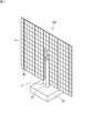
- FIG. 1 is a perspective view of one concentrating solar power generation apparatus as viewed from the light receiving surface side.
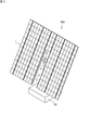
- FIG. 2 is a perspective view of one concentrating solar power generation apparatus as viewed from the back side.
- FIG. 3 is a perspective view showing an example of a state in which the light receiving surface of the photovoltaic panel faces the sun.
- FIG. 4 is a schematic view showing a solar power generation system including, for example, a total of 64 solar power generation device groups, in which eight solar power generation devices are arranged, for example, eight each vertically and horizontally.
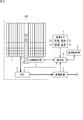
- FIG. 5 is a connection diagram of individual photovoltaic power generation devices and a common part of the entire system.
- FIG. 6 is a connection diagram as a modification of FIG.
- FIG. 7 is a flowchart showing an example of the monitoring control operation by the monitoring control unit.
- the power generation output of the photovoltaic power generation panel becomes AC power via the power conditioner for each of a large number of photovoltaic power generation devices, and is common to all the groups. Provided to substation equipment. On the other hand, attitude control for tracking the sun is performed for each solar power generation device.
- a weather sensor such as a solar radiation sensor for each individual solar power generation device is not a cost-effective measure, a weather sensor is installed at one place where a solar power generation system is installed. There is.
- each solar power generation apparatus is provided with a sub controller for attitude control, and a common main controller that instructs all the sub controllers may be provided at a specific place.
- this indication aims at providing a solar energy power generation system which performs monitoring of the whole system, and tracking control more efficiently.
- This is a solar power generation system configured by collecting a plurality of solar power generation devices that execute the operation of tracking the sun in the daytime, provided corresponding to each group of the solar power generation device Drive control unit, a power conditioner provided corresponding to each group of the solar power generation apparatus, a transformer for consolidating power from the plurality of power conditioners, and the solar power generation apparatus installed Sensor for acquiring information on the weather at the place where it is stored, the remote control of the drive control unit, all the drive control units, all the power conditioners, the substation equipment, and the weather And a monitoring control unit capable of communicating with the sensor and having a function of detecting an abnormality based on the information collected by the communication.
- the monitoring control unit In such a solar power generation system, information on the tracking operation of each solar power generation device and information on the generated power are collected in the monitoring control unit for all the solar power generation devices.
- the monitoring control unit can detect an abnormality based on the collected information.
- the supervisory control unit can place all drive control units under control and play a role as a master controller for tracking. Therefore, monitoring and tracking control of the entire system can be performed more efficiently.
- the monitoring control unit shakes the tracking posture of the solar power generation device within a predetermined range back and forth for each of the azimuth angle and the elevation angle
- the presence or absence of tracking deviation with respect to the sun is determined based on the reaction of the generated electric power, and when it is determined that there is tracking deviation, the corresponding drive control unit is caused to perform calibration operation to eliminate tracking deviation.
- the corresponding drive control unit it is possible to cause the corresponding drive control unit to perform the calibration operation by the monitoring control unit that monitors and controls the plurality of solar power generation devices as a whole.
- the monitoring control unit Among the weather sensors it may be determined that the solar radiation sensor is abnormal. In this case, since it is unlikely that an abnormality occurs simultaneously in all the solar power generation apparatuses, it can be determined that the solar radiation sensor detects a numerical value higher or lower than actual solar radiation.
- the monitoring control unit exists from the place where the solar power generation device is installed through an internet circuit. May be In this case, the monitoring control unit can be placed at any place without being restricted by the place where the solar power generation device is installed.
- FIG.1 and FIG.2 is the perspective view which looked at the photovoltaic power generation apparatus of one group of condensing type from the light-receiving surface side and the back side, respectively.
- the solar power generation device 100 is provided with the solar power generation panel 1 of the shape which continued in the upper part side, and was divided into right and left by the lower part side, and its support apparatus 2.
- FIG. The solar power generation panel (array) 1 is configured by arranging the concentrating solar power generation modules 1M on a rack 11 (FIG. 2) on the back side.
- a solar panel 1 is configured.
- the supporting device 2 includes a support 21, a foundation 22, a two-axis drive unit 23, and a horizontal shaft 24 (FIG. 2) as a drive shaft.
- the lower end of the column 21 is fixed to the base 22 and the upper end thereof is provided with a two-axis drive unit 23.
- a box 13 (FIG. 2) for electrical connection and electrical circuit storage is provided in the vicinity of the lower end of the support 21, a box 13 (FIG. 2) for electrical connection and electrical circuit storage is provided.
- the foundation 22 is firmly buried in the ground to the extent that only the upper surface is visible. With the foundation 22 buried in the ground, the columns 21 become vertical and the horizontal axis 24 becomes horizontal.
- the two-axis drive unit 23 can rotate the horizontal axis 24 in two directions of an azimuth angle (an angle with the column 21 as a central axis) and an elevation angle (an angle with the horizontal axis 24 as a central axis).
- the horizontal shaft 24 is fixed so as to be orthogonal to the reinforcing material 12 which fixes and reinforces the gantry 11. Therefore, when the horizontal axis 24 pivots in the azimuth or elevation direction, the photovoltaic panel 1 also pivots in that direction.
- the support apparatus 2 which supports the solar energy power generation panel 1 by one support
- FIG. 3 is a perspective view showing an example of a state in which the light receiving surface of the solar panel 1 faces the sun.
- the photovoltaic panel 1 changes its posture so as to always face the sun by the two-axis drive unit 23.
- the solar power generation device 100 after sunset has, for example, a horizontal posture with the light receiving surface of the solar power generation panel 1 facing downward, and stands by until the next sunrise.
- FIG. 4 is a schematic view showing a solar power generation system 300 including, for example, a total of 64 solar power generation device groups 200, in which eight solar power generation devices 100 are arranged, for example, eight each vertically and horizontally. is there.
- the monitoring control unit 6 is communicably connected to all the solar power generation devices 100, and can control the posture of each of the solar power generation panels 1 individually or collectively.
- FIG. 5 is an example of the connection diagram of each solar power generation device 100 and the share part of the whole system.
- the photovoltaic power generation apparatus 100 includes, for example, a drive control unit 3 that is incorporated in a box 13 and controls the two-axis driver 23, and power conditioning. And four.
- the drive control unit 3 can control the two-axis drive unit 23 based on, for example, an output signal of a tracking sensor (not shown) to cause the solar panel 1 to perform the tracking operation of the sun. That is, the tracking operation of the sun can be performed independently for each of the solar power generation devices 100.
- the power conditioner 4 converts the output of the photovoltaic panel 1 into AC power and sends it to the substation equipment 5.
- the substation equipment 5 is connected to a power transmission network (not shown).
- the drive control unit 3 can communicate bi-directionally with the monitoring control unit 6 via the communication unit 8.
- the information from the power conditioner 4, the substation device 5, and the weather sensor 7 is sent to the monitoring control unit 6 via the communication unit 8.
- the monitoring control unit 6 plays the role of a master controller for the drive control unit 3. That is, the drive control unit 3 can be instructed to perform the tracking operation. Further, the monitoring control unit 6 can receive information on the tracking operation and error information from the drive control unit 3. Furthermore, the monitoring control unit 6 can receive the information on the generated power and the error information from the power conditioner 4 and can also receive the information on the generated power as the whole system and the error information from the substation 5.
- the communication unit 8 in FIG. 5 may be integrated with the monitoring control unit 6 as one function of the monitoring control unit 6.
- the weather sensor 7 acquires information on the weather in the vicinity of the place where the solar power generation device 100 is installed, and sends the acquired information to the monitoring control unit 6.
- the information on the weather is, for example, each information of a solar radiation sensor 7s, a wind direction sensor 7d, a wind speed sensor 7v, a temperature sensor 7t and the like.
- FIG. 5 illustrates only one solar power generation device 100 for convenience of illustration, but all the solar power generation devices 100 are similarly connected to the substation equipment 5 and the monitoring control unit 6 . Therefore, the substation equipment 5 integrates the output (AC power) from the power conditioner 4 of all the solar power generation devices 100.
- the monitoring control unit 6 may obtain information and error information about the generated power from the power conditioners 4 of all the solar power generation devices 100 and obtain information and error information about the generated power of the entire system from the substation 5 as well. it can. Further, the monitoring control unit 6 can place the drive control units 3 of all the solar power generation devices 100 under its own control, and can acquire information and error information on the tracking operation from all the drive control units 3.
- the monitoring control unit 6 includes a computer, and the computer executes software (computer program) to realize a necessary monitoring control function.
- the software is stored in a storage device (not shown) of the monitoring control unit 6.
- the monitoring control unit 6 may be located at a place where the solar power generation device 100 is installed, or may be present as a server at a remote place.
- FIG. 6 is a connection diagram as a modification of FIG. The difference from FIG. 5 is that only the communication unit 8 is present at or near the place where the solar power generation apparatus 100 is installed, and the monitoring control unit 6 is connected via the Internet line 9, Others are similar. Thus, the monitoring control unit 6 can be placed at any place without being restricted by the place where the solar power generation device 100 is installed.
- monitoring control unit 6 based on the detection output of the weather sensor 7, the monitoring control unit 6 predicts the generated power from the amount of solar radiation (step S1). Next, the monitoring control unit 6 determines whether or not the power generated by any of the solar power generation devices 100 has decreased to 90% or less of the predicted value (step S2). Usually, the actual generated power is higher than 90% of the predicted value. If it is above 90%, there is no problem, and the process ends.
- the monitoring control unit 6 determines an error flag (step S3).
- the error flag is error information indicating a failure or the like, which is sent from the drive control unit 3, the power conditioner 4, and the power transformation device 5. If the error flag can be confirmed, A judgment is made to notify the failure or the like that the error flag means (step S10). Specifically, for example, a failure in the tracking operation, a failure in the power conditioner 4, and a failure in the power transformation equipment 5.
- the monitoring control unit 6 determines whether the same tendency (90% or less) exists in all the solar power generation devices 100 (step S4). Here, if there is a similar tendency, it becomes a B determination (step S11). Specifically, the B determination is a defect of the solar radiation sensor 7s. That is, since it is hard to think that abnormality has generate
- step S4 the monitoring control unit 6 controls the power conditioner 4 and the drive control unit for the photovoltaic power generation device 100 in which the generated power is 90% or less of the predicted value.
- the information of 3 is confirmed (step S5).
- the monitoring control unit 6 first determines whether there is a numerical contradiction in consideration of current / voltage information from the information of the power conditioner 4 (step S6).
- the contradiction is, for example, that the current is small while the voltage is sufficient.
- C determination is made (step S12).
- the C determination is, for example, a determination that a failure in wiring from the photovoltaic panel to the power conditioner 4 is expected.
- a field survey is required to determine the cause.
- step S6 If “No” in step S6, it is estimated that tracking is not performed accurately as a remaining cause, that is, there is tracking deviation. Therefore, the monitoring control unit 6 instructs the drive control unit 3 to shake +0.3 degrees and -0.3 degrees in turn for each of the azimuth angle and the elevation angle with respect to the photovoltaic power generation device 100 in question. (Step S7).
- Step S7 For example, if it is found that the generated power rises when it shakes by +0.3 degrees and the generated power decreases when it shakes by -0.3 degrees, the tracking is shifted to the minus side. Conversely, if -0.3 degrees shake, the generated power rises, and if +0.3 degrees shakes the generated power decrease, the tracking is shifted to the positive side.
- step S8 when the generated power increases (step S8), the D determination is made (step S13).
- the D determination means that there is tracking deviation.
- the monitoring control unit 6 instructs the drive control unit 3 of the photovoltaic power generation device 100 in question to perform a calibration operation (step S14).
- E determination is abnormality of solar power generation panel 1 itself, for example.
- abnormality of the solar radiation sensor 7s it is also considered that the sensitivity of the solar radiation sensor 7s falls. In that case, the predicted value in step S1 of FIG. 7 may decrease, and the generated power may exceed the predicted value. If such a case is also assumed, the abnormality of the solar radiation sensor 7s is detected in step S2 by, for example, an event of rising to 110% or more of the predicted value and an event having the same tendency in all devices (step S4). Is also possible.
- the monitoring control unit 6 can remotely control the drive control unit 3. Further, the monitoring control unit 6 can communicate with all the drive control units 3, all the power conditioners 4, the substation equipment 5, and the weather sensor 7, and the occurrence of an abnormality is generated based on the information collected by communication. It has functions of detection and determination of the type of abnormality.
- the monitoring control unit 6 can detect the occurrence of an abnormality and determine the type of the abnormality based on the collected information.
- the monitoring control unit 6 can place all the drive control units 3 under the control and play a role as a master controller regarding tracking. That is, the monitoring control unit 6 can perform both monitoring and control on all the drive control units 3. According to such a solar power generation system, monitoring and tracking control of the entire system can be performed more efficiently.
Landscapes
- Engineering & Computer Science (AREA)
- Life Sciences & Earth Sciences (AREA)
- Sustainable Development (AREA)
- Power Engineering (AREA)
- Physics & Mathematics (AREA)
- General Physics & Mathematics (AREA)
- Automation & Control Theory (AREA)
- Photovoltaic Devices (AREA)
Abstract
Description
本出願は、2017年10月26日出願の日本出願第2017-207464号に基づく優先権を主張し、前記日本出願に記載された全ての記載内容を援用するものである。
上記のような太陽光発電システムにおいては、例えば、多数の太陽光発電装置の1基ごとに、太陽光発電パネルの発電出力は、パワーコンディショナを介して、交流電力となり、全基に共通の変電機器に提供される。一方、太陽を追尾するための姿勢制御は、個々の太陽光発電装置ごとに行われる。但し、日射センサ等の気象センサを、個々の太陽光発電装置ごとに装備するのはコスト的に得策ではないため、太陽光発電システムが設置されている場所の一箇所に気象センサが設置されている。
かかる課題に鑑み、本開示は、システム全体の監視と追尾制御とをさらに効率的に行う太陽光発電システムを提供することを目的とする。
本開示の太陽光発電システムによれば、システム全体の監視と追尾制御とをさらに効率的に行うことができる。
本発明の実施形態の要旨としては、少なくとも以下のものが含まれる。
この場合、複数基の太陽光発電装置の全体を監視制御する監視制御部により、該当する駆動制御部に較正動作を行わせることができる。
この場合、全ての太陽光発電装置で同時に異常が発生しているとは考えにくいため、日射センサが、実際の日射より高い数値又は低い数値を検出している、と判定することができる。
この場合、監視制御部は、太陽光発電装置が設置されている場所に制約されることなく、任意の場所に置くことができる。
以下、本発明の一実施形態に係る太陽光発電システムについて、図面を参照して説明する。
図1及び図2はそれぞれ、1基分の、集光型の太陽光発電装置を、受光面側及び背面側から見た斜視図である。図1において、太陽光発電装置100は、上部側で連続し、下部側で左右に分かれた形状の太陽光発電パネル1と、その支持装置2とを備えている。太陽光発電パネル(アレイ)1は、背面側の架台11(図2)上に集光型太陽光発電モジュール1Mを並べて構成されている。図1の例では、左右のウイングを構成する(96(=12×8)×2)個と、中央の渡り部分の8個との、合計200個の集光型太陽光発電モジュール1Mの集合体として、太陽光発電パネル1が構成されている。
日没後の太陽光発電装置100は、例えば、太陽光発電パネル1の受光面を下向きにした水平な姿勢となり、翌日の日の出まで待機する。
図4は、一例として、太陽光発電装置100が、例えば縦横にそれぞれ8基ずつ並び、合計64基の太陽光発電装置群200を含む、太陽光発電システム300となっている状態を示す略図である。監視制御部6は、全ての太陽光発電装置100と通信可能に接続されており、各太陽光発電パネル1の姿勢を個別に、又は、統括的に制御することができる。
次に、監視制御部6による監視制御動作の一例について図7のフローチャートを参照して説明する。このフローチャートの処理は定期的に実行される。図において、気象センサ7の検出出力に基づいて、監視制御部6は、日射量から発電電力を予測する(ステップS1)。次に、監視制御部6は、いずれかの太陽光発電装置100の発電電力が、予測値の90%以下まで低下したか否かを判定する(ステップS2)。通常、実際の発電電力は予測値の90%より高い値となる。ここで90%より上であれば、問題は無いので、処理は終了となる。
なお、日射センサ7sの異常に関しては、日射センサ7sの感度が低下することも考えられる。その場合は、図7のステップS1における予測値が低下し、発電電力が予測値を上回ることもあり得る。そのような場合も想定すれば、ステップS2において例えば予測値の110%以上まで上昇という事象と、全装置で同様の傾向あり(ステップS4)の事象とにより、日射センサ7sの異常を検出することも可能である。
以上のように、この太陽光発電システム300では、監視制御部6が、駆動制御部3を遠隔制御可能である。また、監視制御部6は、全ての駆動制御部3、全てのパワーコンディショナ4、変電機器5、及び、気象センサ7と通信可能であり、通信によって収集した情報に基づいて、異常の発生の検出、及び、異常の種類を判定する機能を有する。
なお、今回開示された実施の形態はすべての点で例示であって制限的なものではないと考えられるべきである。本発明の範囲は請求の範囲によって示され、請求の範囲と均等の意味及び範囲内での全ての変更が含まれることが意図される。
1M 集光型太陽光発電モジュール
2 支持装置
3 駆動制御部
4 パワーコンディショナ
5 変電機器
6 監視制御部
7 気象センサ
7d 風向センサ
7s 日射センサ
7t 温度センサ
7v 風速センサ
8 通信部
9 インターネット回線
11 架台
12 補強材
13 ボックス
21 支柱
22 基礎
23 2軸駆動部
24 水平軸
100 太陽光発電装置
200 太陽光発電装置群
300 太陽光発電システム
Claims (4)
- 日中に太陽を追尾する動作を実行する太陽光発電装置が複数基集まって構成される太陽光発電システムであって、
前記太陽光発電装置の各基に対応して設けられた駆動制御部と、
前記太陽光発電装置の各基に対応して設けられたパワーコンディショナと、
複数の前記パワーコンディショナからの電力を集約する変電機器と、
前記太陽光発電装置が設置されている場所の気象に関する情報を取得する気象センサと、
前記駆動制御部を遠隔制御可能であり、また、全ての前記駆動制御部、全ての前記パワーコンディショナ、前記変電機器、及び、前記気象センサと通信可能であり、通信によって収集した情報に基づいて異常を検出する機能を有する監視制御部と、
を備えている太陽光発電システム。 - 前記監視制御部は、前記太陽光発電装置について、追尾の姿勢を方位角及び仰角のそれぞれについて前後に所定範囲内で振った場合の発電電力の反応に基づいて、太陽に対する追尾のずれの有無を判定し、追尾ずれがあると判定した場合は、該当する前記駆動制御部に対して、追尾ずれを解消する較正動作を行わせる請求項1に記載の太陽光発電システム。
- 前記監視制御部は、全ての前記太陽光発電装置で、発電電力が予測値に対して同程度にずれている場合、前記気象センサのうち、日射センサに異常があると判定する請求項1又は請求項2に記載の太陽光発電システム。
- 前記監視制御部は、前記太陽光発電装置が設置されている場所からインターネット回線を介して存在する請求項1~請求項3のいずれか1項に記載の太陽光発電システム。
Priority Applications (5)
| Application Number | Priority Date | Filing Date | Title |
|---|---|---|---|
| JP2019550886A JPWO2019082589A1 (ja) | 2017-10-26 | 2018-09-27 | 太陽光発電システム |
| US16/755,239 US20200244215A1 (en) | 2017-10-26 | 2018-09-27 | Photovoltaic system |
| EP18871690.6A EP3703252A4 (en) | 2017-10-26 | 2018-09-27 | SOLAR ENERGY GENERATION SYSTEM |
| AU2018356694A AU2018356694A1 (en) | 2017-10-26 | 2018-09-27 | Solar power generation system |
| CN201880069407.6A CN111264028A (zh) | 2017-10-26 | 2018-09-27 | 光伏系统 |
Applications Claiming Priority (2)
| Application Number | Priority Date | Filing Date | Title |
|---|---|---|---|
| JP2017-207464 | 2017-10-26 | ||
| JP2017207464 | 2017-10-26 |
Publications (1)
| Publication Number | Publication Date |
|---|---|
| WO2019082589A1 true WO2019082589A1 (ja) | 2019-05-02 |
Family
ID=66247452
Family Applications (1)
| Application Number | Title | Priority Date | Filing Date |
|---|---|---|---|
| PCT/JP2018/035990 Ceased WO2019082589A1 (ja) | 2017-10-26 | 2018-09-27 | 太陽光発電システム |
Country Status (8)
| Country | Link |
|---|---|
| US (1) | US20200244215A1 (ja) |
| EP (1) | EP3703252A4 (ja) |
| JP (1) | JPWO2019082589A1 (ja) |
| CN (1) | CN111264028A (ja) |
| AU (1) | AU2018356694A1 (ja) |
| MA (1) | MA50845A (ja) |
| TW (1) | TW201931760A (ja) |
| WO (1) | WO2019082589A1 (ja) |
Families Citing this family (4)
| Publication number | Priority date | Publication date | Assignee | Title |
|---|---|---|---|---|
| CN113189914A (zh) * | 2021-05-14 | 2021-07-30 | 江苏中信博新能源科技股份有限公司 | 一种光伏支架控制方法及系统 |
| CN113206636B (zh) * | 2021-05-17 | 2022-05-13 | 北京鑫泰绿能科技有限公司 | 一种光伏电站工作监测系统及监测方法 |
| CN120615277A (zh) * | 2023-01-31 | 2025-09-09 | 耐克斯特拉克尔有限责任公司 | 跟踪器健康状况 |
| WO2026054692A1 (en) * | 2024-09-06 | 2026-03-12 | Vaja Ab | Solar panel system(s) and method(s) for vertical tracking |
Citations (4)
| Publication number | Priority date | Publication date | Assignee | Title |
|---|---|---|---|---|
| JP2014226025A (ja) | 2013-04-23 | 2014-12-04 | 住友電気工業株式会社 | 集光型太陽光発電システム並びに追尾ずれの検出方法及び追尾ずれの補正方法 |
| JP2015223040A (ja) * | 2014-05-23 | 2015-12-10 | 住友電気工業株式会社 | 集光型太陽光発電システム、これに用いる半導体集積回路、追尾ずれの検出プログラム及び追尾ずれの補正プログラム、並びに、追尾ずれの検出方法及び追尾ずれの補正方法 |
| JP2017169321A (ja) * | 2016-03-15 | 2017-09-21 | オムロン株式会社 | 要因推定装置、要因推定装置の制御方法、制御プログラムおよび記録媒体 |
| JP2017207464A (ja) | 2016-05-17 | 2017-11-24 | アンリツ株式会社 | アンテナ測定システム及びアンテナ測定方法 |
Family Cites Families (1)
| Publication number | Priority date | Publication date | Assignee | Title |
|---|---|---|---|---|
| US8502129B2 (en) * | 2010-02-16 | 2013-08-06 | Western Gas And Electric, Inc. | Integrated remotely controlled photovoltaic system |
-
2018
- 2018-09-27 AU AU2018356694A patent/AU2018356694A1/en not_active Abandoned
- 2018-09-27 MA MA050845A patent/MA50845A/fr unknown
- 2018-09-27 CN CN201880069407.6A patent/CN111264028A/zh active Pending
- 2018-09-27 WO PCT/JP2018/035990 patent/WO2019082589A1/ja not_active Ceased
- 2018-09-27 US US16/755,239 patent/US20200244215A1/en not_active Abandoned
- 2018-09-27 EP EP18871690.6A patent/EP3703252A4/en not_active Withdrawn
- 2018-09-27 JP JP2019550886A patent/JPWO2019082589A1/ja active Pending
- 2018-10-15 TW TW107136131A patent/TW201931760A/zh unknown
Patent Citations (4)
| Publication number | Priority date | Publication date | Assignee | Title |
|---|---|---|---|---|
| JP2014226025A (ja) | 2013-04-23 | 2014-12-04 | 住友電気工業株式会社 | 集光型太陽光発電システム並びに追尾ずれの検出方法及び追尾ずれの補正方法 |
| JP2015223040A (ja) * | 2014-05-23 | 2015-12-10 | 住友電気工業株式会社 | 集光型太陽光発電システム、これに用いる半導体集積回路、追尾ずれの検出プログラム及び追尾ずれの補正プログラム、並びに、追尾ずれの検出方法及び追尾ずれの補正方法 |
| JP2017169321A (ja) * | 2016-03-15 | 2017-09-21 | オムロン株式会社 | 要因推定装置、要因推定装置の制御方法、制御プログラムおよび記録媒体 |
| JP2017207464A (ja) | 2016-05-17 | 2017-11-24 | アンリツ株式会社 | アンテナ測定システム及びアンテナ測定方法 |
Non-Patent Citations (1)
| Title |
|---|
| See also references of EP3703252A4 * |
Also Published As
| Publication number | Publication date |
|---|---|
| CN111264028A (zh) | 2020-06-09 |
| AU2018356694A1 (en) | 2020-05-07 |
| EP3703252A1 (en) | 2020-09-02 |
| JPWO2019082589A1 (ja) | 2020-11-26 |
| EP3703252A4 (en) | 2021-05-12 |
| MA50845A (fr) | 2020-09-02 |
| TW201931760A (zh) | 2019-08-01 |
| US20200244215A1 (en) | 2020-07-30 |
Similar Documents
| Publication | Publication Date | Title |
|---|---|---|
| US8288644B2 (en) | Photovoltaic power generation system and photovoltaic power generation system control method | |
| US10520224B2 (en) | Drive with integrated inclination sensor | |
| KR101295529B1 (ko) | 태양전지판의 고장진단 원격감시 시스템 | |
| EP3794726B1 (en) | Systems for detecting shading for solar trackers | |
| CN101970951A (zh) | 用于太阳能设备的控制系统 | |
| JPWO2019082589A1 (ja) | 太陽光発電システム | |
| KR101299960B1 (ko) | 계통 연계형 태양광발전 시스템 | |
| JP2011134862A (ja) | 太陽光発電システム | |
| KR101131482B1 (ko) | 고효율 태양광 발전시스템 | |
| JP2015223040A (ja) | 集光型太陽光発電システム、これに用いる半導体集積回路、追尾ずれの検出プログラム及び追尾ずれの補正プログラム、並びに、追尾ずれの検出方法及び追尾ずれの補正方法 | |
| KR101699495B1 (ko) | 태양광 발전장치용 모니터링 장치 | |
| WO2019027079A1 (ko) | 군집 태양광 트래커들의 제어 방법 및 시스템 | |
| US20130019920A1 (en) | Combination solar cell sun sensor for direct alignment of trackers and closed-loop tracking | |
| EP3751730B1 (en) | Solar power generation device and method of controlling solar power generation device | |
| KR20130110981A (ko) | 하나의 중앙제어장치를 구비한 태양광 발전시스템 | |
| KR20160098824A (ko) | 태양광발전 시스템 | |
| KR100959952B1 (ko) | 일축방식의 대면적 태양광발전 추적장치 | |
| WO2019030996A1 (ja) | 太陽光発電システム及び、太陽光発電パネルの姿勢制御方法 | |
| JP2013228794A (ja) | 太陽電池システム | |
| KR102542205B1 (ko) | 태양광 발전설비 모니터링 시스템 | |
| KR20090076880A (ko) | 전위차를 이용한 추적식 태양광발전 시스템 | |
| CN213846253U (zh) | 一种太阳能储能报警通信系统 | |
| CN206490643U (zh) | 一种光伏逆变房 | |
| WO2020261960A1 (ja) | 集光型太陽光発電装置の監視システム、追尾ずれの検出方法、及び、追尾ずれの検出プログラム | |
| JP2016136802A (ja) | 太陽電池パネルの設備管理システム |
Legal Events
| Date | Code | Title | Description |
|---|---|---|---|
| 121 | Ep: the epo has been informed by wipo that ep was designated in this application |
Ref document number: 18871690 Country of ref document: EP Kind code of ref document: A1 |
|
| ENP | Entry into the national phase |
Ref document number: 2019550886 Country of ref document: JP Kind code of ref document: A |
|
| NENP | Non-entry into the national phase |
Ref country code: DE |
|
| ENP | Entry into the national phase |
Ref document number: 2018356694 Country of ref document: AU Date of ref document: 20180927 Kind code of ref document: A |
|
| ENP | Entry into the national phase |
Ref document number: 2018871690 Country of ref document: EP Effective date: 20200526 |