WO2019083047A1 - 蓄圧容器 - Google Patents
蓄圧容器Info
- Publication number
- WO2019083047A1 WO2019083047A1 PCT/JP2018/040001 JP2018040001W WO2019083047A1 WO 2019083047 A1 WO2019083047 A1 WO 2019083047A1 JP 2018040001 W JP2018040001 W JP 2018040001W WO 2019083047 A1 WO2019083047 A1 WO 2019083047A1
- Authority
- WO
- WIPO (PCT)
- Prior art keywords
- pressure accumulation
- reinforcing ring
- pressure
- container
- accumulation chamber
- Prior art date
- Legal status (The legal status is an assumption and is not a legal conclusion. Google has not performed a legal analysis and makes no representation as to the accuracy of the status listed.)
- Ceased
Links
Images




Classifications
-
- F—MECHANICAL ENGINEERING; LIGHTING; HEATING; WEAPONS; BLASTING
- F17—STORING OR DISTRIBUTING GASES OR LIQUIDS
- F17C—VESSELS FOR CONTAINING OR STORING COMPRESSED, LIQUEFIED OR SOLIDIFIED GASES; FIXED-CAPACITY GAS-HOLDERS; FILLING VESSELS WITH, OR DISCHARGING FROM VESSELS, COMPRESSED, LIQUEFIED, OR SOLIDIFIED GASES
- F17C1/00—Pressure vessels, e.g. gas cylinder, gas tank, replaceable cartridge
- F17C1/02—Pressure vessels, e.g. gas cylinder, gas tank, replaceable cartridge involving reinforcing arrangements
-
- F—MECHANICAL ENGINEERING; LIGHTING; HEATING; WEAPONS; BLASTING
- F17—STORING OR DISTRIBUTING GASES OR LIQUIDS
- F17C—VESSELS FOR CONTAINING OR STORING COMPRESSED, LIQUEFIED OR SOLIDIFIED GASES; FIXED-CAPACITY GAS-HOLDERS; FILLING VESSELS WITH, OR DISCHARGING FROM VESSELS, COMPRESSED, LIQUEFIED, OR SOLIDIFIED GASES
- F17C13/00—Details of vessels or of the filling or discharging of vessels
- F17C13/002—Details of vessels or of the filling or discharging of vessels for vessels under pressure
-
- F—MECHANICAL ENGINEERING; LIGHTING; HEATING; WEAPONS; BLASTING
- F17—STORING OR DISTRIBUTING GASES OR LIQUIDS
- F17C—VESSELS FOR CONTAINING OR STORING COMPRESSED, LIQUEFIED OR SOLIDIFIED GASES; FIXED-CAPACITY GAS-HOLDERS; FILLING VESSELS WITH, OR DISCHARGING FROM VESSELS, COMPRESSED, LIQUEFIED, OR SOLIDIFIED GASES
- F17C1/00—Pressure vessels, e.g. gas cylinder, gas tank, replaceable cartridge
- F17C1/16—Pressure vessels, e.g. gas cylinder, gas tank, replaceable cartridge constructed of plastics materials
-
- F—MECHANICAL ENGINEERING; LIGHTING; HEATING; WEAPONS; BLASTING
- F17—STORING OR DISTRIBUTING GASES OR LIQUIDS
- F17C—VESSELS FOR CONTAINING OR STORING COMPRESSED, LIQUEFIED OR SOLIDIFIED GASES; FIXED-CAPACITY GAS-HOLDERS; FILLING VESSELS WITH, OR DISCHARGING FROM VESSELS, COMPRESSED, LIQUEFIED, OR SOLIDIFIED GASES
- F17C1/00—Pressure vessels, e.g. gas cylinder, gas tank, replaceable cartridge
- F17C1/14—Pressure vessels, e.g. gas cylinder, gas tank, replaceable cartridge constructed of aluminium; constructed of non-magnetic steel
-
- F—MECHANICAL ENGINEERING; LIGHTING; HEATING; WEAPONS; BLASTING
- F17—STORING OR DISTRIBUTING GASES OR LIQUIDS
- F17C—VESSELS FOR CONTAINING OR STORING COMPRESSED, LIQUEFIED OR SOLIDIFIED GASES; FIXED-CAPACITY GAS-HOLDERS; FILLING VESSELS WITH, OR DISCHARGING FROM VESSELS, COMPRESSED, LIQUEFIED, OR SOLIDIFIED GASES
- F17C5/00—Methods or apparatus for filling containers with liquefied, solidified, or compressed gases under pressures
- F17C5/06—Methods or apparatus for filling containers with liquefied, solidified, or compressed gases under pressures for filling with compressed gases
-
- F—MECHANICAL ENGINEERING; LIGHTING; HEATING; WEAPONS; BLASTING
- F17—STORING OR DISTRIBUTING GASES OR LIQUIDS
- F17C—VESSELS FOR CONTAINING OR STORING COMPRESSED, LIQUEFIED OR SOLIDIFIED GASES; FIXED-CAPACITY GAS-HOLDERS; FILLING VESSELS WITH, OR DISCHARGING FROM VESSELS, COMPRESSED, LIQUEFIED, OR SOLIDIFIED GASES
- F17C2201/00—Vessel construction, in particular geometry, arrangement or size
- F17C2201/01—Shape
- F17C2201/0104—Shape cylindrical
-
- F—MECHANICAL ENGINEERING; LIGHTING; HEATING; WEAPONS; BLASTING
- F17—STORING OR DISTRIBUTING GASES OR LIQUIDS
- F17C—VESSELS FOR CONTAINING OR STORING COMPRESSED, LIQUEFIED OR SOLIDIFIED GASES; FIXED-CAPACITY GAS-HOLDERS; FILLING VESSELS WITH, OR DISCHARGING FROM VESSELS, COMPRESSED, LIQUEFIED, OR SOLIDIFIED GASES
- F17C2201/00—Vessel construction, in particular geometry, arrangement or size
- F17C2201/01—Shape
- F17C2201/0104—Shape cylindrical
- F17C2201/0119—Shape cylindrical with flat end-piece
-
- F—MECHANICAL ENGINEERING; LIGHTING; HEATING; WEAPONS; BLASTING
- F17—STORING OR DISTRIBUTING GASES OR LIQUIDS
- F17C—VESSELS FOR CONTAINING OR STORING COMPRESSED, LIQUEFIED OR SOLIDIFIED GASES; FIXED-CAPACITY GAS-HOLDERS; FILLING VESSELS WITH, OR DISCHARGING FROM VESSELS, COMPRESSED, LIQUEFIED, OR SOLIDIFIED GASES
- F17C2201/00—Vessel construction, in particular geometry, arrangement or size
- F17C2201/05—Size
- F17C2201/056—Small (<1 m3)
-
- F—MECHANICAL ENGINEERING; LIGHTING; HEATING; WEAPONS; BLASTING
- F17—STORING OR DISTRIBUTING GASES OR LIQUIDS
- F17C—VESSELS FOR CONTAINING OR STORING COMPRESSED, LIQUEFIED OR SOLIDIFIED GASES; FIXED-CAPACITY GAS-HOLDERS; FILLING VESSELS WITH, OR DISCHARGING FROM VESSELS, COMPRESSED, LIQUEFIED, OR SOLIDIFIED GASES
- F17C2203/00—Vessel construction, in particular walls or details thereof
- F17C2203/01—Reinforcing or suspension means
- F17C2203/011—Reinforcing means
-
- F—MECHANICAL ENGINEERING; LIGHTING; HEATING; WEAPONS; BLASTING
- F17—STORING OR DISTRIBUTING GASES OR LIQUIDS
- F17C—VESSELS FOR CONTAINING OR STORING COMPRESSED, LIQUEFIED OR SOLIDIFIED GASES; FIXED-CAPACITY GAS-HOLDERS; FILLING VESSELS WITH, OR DISCHARGING FROM VESSELS, COMPRESSED, LIQUEFIED, OR SOLIDIFIED GASES
- F17C2203/00—Vessel construction, in particular walls or details thereof
- F17C2203/01—Reinforcing or suspension means
- F17C2203/011—Reinforcing means
- F17C2203/012—Reinforcing means on or in the wall, e.g. ribs
-
- F—MECHANICAL ENGINEERING; LIGHTING; HEATING; WEAPONS; BLASTING
- F17—STORING OR DISTRIBUTING GASES OR LIQUIDS
- F17C—VESSELS FOR CONTAINING OR STORING COMPRESSED, LIQUEFIED OR SOLIDIFIED GASES; FIXED-CAPACITY GAS-HOLDERS; FILLING VESSELS WITH, OR DISCHARGING FROM VESSELS, COMPRESSED, LIQUEFIED, OR SOLIDIFIED GASES
- F17C2203/00—Vessel construction, in particular walls or details thereof
- F17C2203/06—Materials for walls or layers thereof; Properties or structures of walls or their materials
- F17C2203/0602—Wall structures; Special features thereof
- F17C2203/0612—Wall structures
- F17C2203/0614—Single wall
- F17C2203/0617—Single wall with one layer
-
- F—MECHANICAL ENGINEERING; LIGHTING; HEATING; WEAPONS; BLASTING
- F17—STORING OR DISTRIBUTING GASES OR LIQUIDS
- F17C—VESSELS FOR CONTAINING OR STORING COMPRESSED, LIQUEFIED OR SOLIDIFIED GASES; FIXED-CAPACITY GAS-HOLDERS; FILLING VESSELS WITH, OR DISCHARGING FROM VESSELS, COMPRESSED, LIQUEFIED, OR SOLIDIFIED GASES
- F17C2203/00—Vessel construction, in particular walls or details thereof
- F17C2203/06—Materials for walls or layers thereof; Properties or structures of walls or their materials
- F17C2203/0634—Materials for walls or layers thereof
- F17C2203/0636—Metals
- F17C2203/0639—Steels
-
- F—MECHANICAL ENGINEERING; LIGHTING; HEATING; WEAPONS; BLASTING
- F17—STORING OR DISTRIBUTING GASES OR LIQUIDS
- F17C—VESSELS FOR CONTAINING OR STORING COMPRESSED, LIQUEFIED OR SOLIDIFIED GASES; FIXED-CAPACITY GAS-HOLDERS; FILLING VESSELS WITH, OR DISCHARGING FROM VESSELS, COMPRESSED, LIQUEFIED, OR SOLIDIFIED GASES
- F17C2203/00—Vessel construction, in particular walls or details thereof
- F17C2203/06—Materials for walls or layers thereof; Properties or structures of walls or their materials
- F17C2203/0634—Materials for walls or layers thereof
- F17C2203/0658—Synthetics
- F17C2203/066—Plastics
-
- F—MECHANICAL ENGINEERING; LIGHTING; HEATING; WEAPONS; BLASTING
- F17—STORING OR DISTRIBUTING GASES OR LIQUIDS
- F17C—VESSELS FOR CONTAINING OR STORING COMPRESSED, LIQUEFIED OR SOLIDIFIED GASES; FIXED-CAPACITY GAS-HOLDERS; FILLING VESSELS WITH, OR DISCHARGING FROM VESSELS, COMPRESSED, LIQUEFIED, OR SOLIDIFIED GASES
- F17C2205/00—Vessel construction, in particular mounting arrangements, attachments or identifications means
- F17C2205/03—Fluid connections, filters, valves, closure means or other attachments
- F17C2205/0302—Fittings, valves, filters, or components in connection with the gas storage device
- F17C2205/0311—Closure means
-
- F—MECHANICAL ENGINEERING; LIGHTING; HEATING; WEAPONS; BLASTING
- F17—STORING OR DISTRIBUTING GASES OR LIQUIDS
- F17C—VESSELS FOR CONTAINING OR STORING COMPRESSED, LIQUEFIED OR SOLIDIFIED GASES; FIXED-CAPACITY GAS-HOLDERS; FILLING VESSELS WITH, OR DISCHARGING FROM VESSELS, COMPRESSED, LIQUEFIED, OR SOLIDIFIED GASES
- F17C2209/00—Vessel construction, in particular methods of manufacturing
- F17C2209/22—Assembling processes
- F17C2209/224—Press-fitting; Shrink-fitting
-
- F—MECHANICAL ENGINEERING; LIGHTING; HEATING; WEAPONS; BLASTING
- F17—STORING OR DISTRIBUTING GASES OR LIQUIDS
- F17C—VESSELS FOR CONTAINING OR STORING COMPRESSED, LIQUEFIED OR SOLIDIFIED GASES; FIXED-CAPACITY GAS-HOLDERS; FILLING VESSELS WITH, OR DISCHARGING FROM VESSELS, COMPRESSED, LIQUEFIED, OR SOLIDIFIED GASES
- F17C2209/00—Vessel construction, in particular methods of manufacturing
- F17C2209/22—Assembling processes
- F17C2209/228—Assembling processes by screws, bolts or rivets
-
- F—MECHANICAL ENGINEERING; LIGHTING; HEATING; WEAPONS; BLASTING
- F17—STORING OR DISTRIBUTING GASES OR LIQUIDS
- F17C—VESSELS FOR CONTAINING OR STORING COMPRESSED, LIQUEFIED OR SOLIDIFIED GASES; FIXED-CAPACITY GAS-HOLDERS; FILLING VESSELS WITH, OR DISCHARGING FROM VESSELS, COMPRESSED, LIQUEFIED, OR SOLIDIFIED GASES
- F17C2221/00—Handled fluid, in particular type of fluid
- F17C2221/01—Pure fluids
- F17C2221/012—Hydrogen
-
- F—MECHANICAL ENGINEERING; LIGHTING; HEATING; WEAPONS; BLASTING
- F17—STORING OR DISTRIBUTING GASES OR LIQUIDS
- F17C—VESSELS FOR CONTAINING OR STORING COMPRESSED, LIQUEFIED OR SOLIDIFIED GASES; FIXED-CAPACITY GAS-HOLDERS; FILLING VESSELS WITH, OR DISCHARGING FROM VESSELS, COMPRESSED, LIQUEFIED, OR SOLIDIFIED GASES
- F17C2223/00—Handled fluid before transfer, i.e. state of fluid when stored in the vessel or before transfer from the vessel
- F17C2223/01—Handled fluid before transfer, i.e. state of fluid when stored in the vessel or before transfer from the vessel characterised by the phase
- F17C2223/0107—Single phase
- F17C2223/0123—Single phase gaseous, e.g. CNG, GNC
-
- F—MECHANICAL ENGINEERING; LIGHTING; HEATING; WEAPONS; BLASTING
- F17—STORING OR DISTRIBUTING GASES OR LIQUIDS
- F17C—VESSELS FOR CONTAINING OR STORING COMPRESSED, LIQUEFIED OR SOLIDIFIED GASES; FIXED-CAPACITY GAS-HOLDERS; FILLING VESSELS WITH, OR DISCHARGING FROM VESSELS, COMPRESSED, LIQUEFIED, OR SOLIDIFIED GASES
- F17C2223/00—Handled fluid before transfer, i.e. state of fluid when stored in the vessel or before transfer from the vessel
- F17C2223/03—Handled fluid before transfer, i.e. state of fluid when stored in the vessel or before transfer from the vessel characterised by the pressure level
- F17C2223/036—Very high pressure (>80 bar)
-
- F—MECHANICAL ENGINEERING; LIGHTING; HEATING; WEAPONS; BLASTING
- F17—STORING OR DISTRIBUTING GASES OR LIQUIDS
- F17C—VESSELS FOR CONTAINING OR STORING COMPRESSED, LIQUEFIED OR SOLIDIFIED GASES; FIXED-CAPACITY GAS-HOLDERS; FILLING VESSELS WITH, OR DISCHARGING FROM VESSELS, COMPRESSED, LIQUEFIED, OR SOLIDIFIED GASES
- F17C2260/00—Purposes of gas storage and gas handling
- F17C2260/01—Improving mechanical properties or manufacturing
- F17C2260/011—Improving strength
-
- F—MECHANICAL ENGINEERING; LIGHTING; HEATING; WEAPONS; BLASTING
- F17—STORING OR DISTRIBUTING GASES OR LIQUIDS
- F17C—VESSELS FOR CONTAINING OR STORING COMPRESSED, LIQUEFIED OR SOLIDIFIED GASES; FIXED-CAPACITY GAS-HOLDERS; FILLING VESSELS WITH, OR DISCHARGING FROM VESSELS, COMPRESSED, LIQUEFIED, OR SOLIDIFIED GASES
- F17C2270/00—Applications
- F17C2270/01—Applications for fluid transport or storage
- F17C2270/0165—Applications for fluid transport or storage on the road
- F17C2270/0168—Applications for fluid transport or storage on the road by vehicles
- F17C2270/0178—Cars
-
- F—MECHANICAL ENGINEERING; LIGHTING; HEATING; WEAPONS; BLASTING
- F17—STORING OR DISTRIBUTING GASES OR LIQUIDS
- F17C—VESSELS FOR CONTAINING OR STORING COMPRESSED, LIQUEFIED OR SOLIDIFIED GASES; FIXED-CAPACITY GAS-HOLDERS; FILLING VESSELS WITH, OR DISCHARGING FROM VESSELS, COMPRESSED, LIQUEFIED, OR SOLIDIFIED GASES
- F17C2270/00—Applications
- F17C2270/01—Applications for fluid transport or storage
- F17C2270/0165—Applications for fluid transport or storage on the road
- F17C2270/0184—Fuel cells
-
- Y—GENERAL TAGGING OF NEW TECHNOLOGICAL DEVELOPMENTS; GENERAL TAGGING OF CROSS-SECTIONAL TECHNOLOGIES SPANNING OVER SEVERAL SECTIONS OF THE IPC; TECHNICAL SUBJECTS COVERED BY FORMER USPC CROSS-REFERENCE ART COLLECTIONS [XRACs] AND DIGESTS
- Y02—TECHNOLOGIES OR APPLICATIONS FOR MITIGATION OR ADAPTATION AGAINST CLIMATE CHANGE
- Y02E—REDUCTION OF GREENHOUSE GAS [GHG] EMISSIONS, RELATED TO ENERGY GENERATION, TRANSMISSION OR DISTRIBUTION
- Y02E60/00—Enabling technologies; Technologies with a potential or indirect contribution to GHG emissions mitigation
- Y02E60/30—Hydrogen technology
- Y02E60/32—Hydrogen storage
Definitions
- the present invention relates to a pressure accumulation container provided with a pressure accumulation chamber capable of containing hydrogen gas and the like.
- an accumulator container for storing and transporting high pressure hydrogen gas used in a hydrogen station or the like can be mentioned.
- Accumulators are conventionally manufactured using high strength low alloy steel such as Cr-Mo steel.
- the screw portion is caused by so-called hydrogen environment embrittlement. It is feared that the strength and ductility of a stress concentration point (e.g., a screwing portion between a male screw and a female screw) in the above may be reduced.
- embrittlement of the pressure accumulation container is not preferable because it can be a cause of lowering the pressure accumulation performance of the pressure accumulation container.
- one conventional pressure accumulation container has a structure in which a lid-like structure is sandwiched between the screwed portion and the pressure accumulation chamber so that the screwed portion and hydrogen are not in direct contact (so-called screwed nut lid structure ) Is adopted.
- this conventional pressure-accumulation container is designed to suppress the occurrence of hydrogen environment embrittlement in the screwing portion (for example, the screw bottom) of the male screw and female screw of the screwed portion (for example, See Patent Document 1).
- the lid-like structure is normally held at a predetermined position by the screw-in portion.
- the force exerted by the gas in the pressure accumulation chamber on the lid-like structure is transmitted to the screw-in portion through the lid-like structure and finally acts on the screw-in portion of the screw-in portion. Therefore, apart from hydrogen environment embrittlement, there is a concern that fatigue cracks may occur in the screwed part due to the stress generated in the screwed part of the screwed part (in particular, near the first thread closest to the pressure accumulation chamber). Ru.
- One of the objects of the present invention is to provide a pressure-accumulating container capable of achieving both suppression of hydrogen environment embrittlement of a screw-in portion of a pressure-accumulating container and suppression of fatigue cracks.
- an accumulator container is A cylinder portion defining an accumulator chamber inside; A screwed portion disposed inside at least one of the both end portions of the cylinder portion, wherein the inner peripheral portion of the cylinder portion and the outer peripheral portion of the screwed portion are screwed together; A lid portion disposed at a position closer to the pressure accumulation chamber than the screwed portion and having a pressure receiving surface facing the pressure accumulation chamber; It is a reinforcing ring fitted to the outer peripheral surface of the cylinder portion, and a portion on the outer peripheral surface corresponding to a part or all of a screwing portion between the cylinder portion and the screwed portion in the axial direction of the cylinder portion And a reinforcing ring that covers along.
- the lid is provided between the screw-in portion and the pressure accumulation chamber, so that even if hydrogen is contained in the pressure accumulation chamber, hydrogen can be in direct contact with the screw-in portion Be suppressed.
- a reinforcing ring provided so as to cover the outer peripheral surface of the cylinder portion corresponds to a part or all of the screwing portion between the screwed portion and the cylinder portion And covers the outer peripheral surface of the cylinder portion.
- the accumulator container is It further comprises a seal part for sealing a gap between the lid part and the cylinder part,
- the reinforcing ring is The axial-direction end of the reinforcing ring on the pressure-accumulation chamber side is at a position on the outer peripheral surface corresponding to the seal portion, or the shaft rather than the position on the outer peripheral surface corresponding to the seal portion It is configured to be at a position on the accumulator chamber side in the direction.
- the sealing portion further appropriately suppresses the contact of the gas in the pressure accumulation chamber with the threaded portion.
- the “end on the pressure accumulation chamber side” of the reinforcing ring is closer to the pressure accumulation chamber than the position on the outer peripheral surface of the cylinder corresponding to the seal or the position on the outer peripheral surface of the cylinder corresponding to the seal In position.
- the reinforcing ring is The end of the reinforcing ring on the side opposite to the pressure accumulation chamber in the axial direction is located on the outer peripheral surface corresponding to the end on the side opposite to the pressure accumulation chamber of the screwing portion, or
- the screw connection portion is configured to be located at a position farther from the pressure accumulation chamber in the axial direction than a position on the outer peripheral surface corresponding to an end opposite to the pressure accumulation chamber.
- the end opposite to the pressure accumulation chamber of the reinforcing ring is the pressure accumulation chamber rather than the position corresponding to the end of the screwing portion or the position corresponding to the end of the screwing portion It is located away from. According to experiments and studies conducted by the inventor, it has become clear that the occurrence of fatigue cracks in the screwed portion can be suppressed by arranging the reinforcing ring at such a position (FIG. 7 (a) and FIG. 7). 7 (b)). Therefore, the pressure-accumulation container concerning a 3rd side can control a fatigue crack of a screw-in part still more certainly.
- the accumulator container is When the pressure in the pressure accumulation chamber fluctuates within a range of 82 MPa or less and 50 MPa or more, the difference between the maximum value and the minimum value of the stress generated in the screwing portion is 300 MPa or less.
- the difference between the maximum value and the minimum value of the stress generated in the screwed portion by attaching the reinforcing ring to the cylinder portion (hereinafter referred to as “stress range” ) Can be reduced (see FIGS. 6 (a), 6 (b), 7 (a) and 7 (b)).
- stress range in the case where the pressure in the pressure accumulation chamber fluctuates within the range of 82 MPa to 50 MPa is 300 MPa or less, even when the pressure in the pressure accumulation chamber becomes particularly high like the hydrogen storage container at the hydrogen station,
- the pressure accumulation container of the invention can be used.
- the cylinder portion is designed using a thin pipe satisfying this condition and having a safety factor of 2.4 or more, it can contribute to the miniaturization of the hydrogen storage container at the hydrogen station.
- the “safety factor” is a value calculated by “tensile strength of steel material constituting thin wall pipe / maximum stress assumed in design of thin wall pipe” (for example, non-patent documents 2 to See 4).
- the reinforcing ring is It is fitted to the cylinder portion in a state of applying a compressive stress so as to clamp the cylinder portion.
- the effect of protecting the seal portion and the screwed portion is enhanced, and hydrogen environment embrittlement and fatigue cracking can be suppressed more reliably.
- such a tightening can be realized by shrink-fitting the reinforcing ring to the cylinder portion.
- the thickness of the reinforcing ring in the radial direction of the cylinder portion is 5% or more and 10% or less of the outer diameter of the cylinder portion.
- the reinforcing ring has a thickness within such a range to protect the seal portion and the screwed portion, and the product of the pressure accumulation container. It became clear that it could be compatible with the economy and the weight.
- the lid portion has an extending portion extending outward in the radial direction of the cylinder portion,
- the screwing portion has a recessed portion which is recessed outward in the radial direction,
- the elongated material portion and the depressed portion abut in the axial direction;
- the outer peripheral edge on the pressure accumulation chamber side of the screwed portion and the lid portion are configured to be separated in the axial direction.
- the pressure-accumulation container concerning the 7th side can control generating of a fatigue crack still more certainly.
- the cylinder portion has a straight cylindrical and cylindrical shape.
- the cylinder portion has a straight cylinder (that is, a non-curved cylindrical shape) and a cylindrical shape, so that the cylinder portion can be manufactured more precisely at the time of manufacturing than the case where the cylinder portion is curved. Processing is possible. Therefore, it can suppress that a process damage
- the ninth aspect provides a pressure-accumulated container that can withstand long-term practical use as a container for storing hydrogen at a hydrogen station by having a fatigue crack life of at least 400,000 times in fatigue crack growth analysis according to the above criteria. it can.
- 400,000 times is a value assuming that the pressure accumulation container is exposed to about 100 times of pressure increase and decrease per day for about 10 years.
- FIG. 1 is a cross-sectional view showing a pressure accumulation container according to an embodiment of the present invention.
- FIG. 2 is an enlarged cross-sectional view showing a part of the pressure accumulation container shown in FIG.
- FIG. 3 is a cross-sectional view showing a part of a pressure accumulation container according to a comparative example.
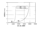
- FIG. 4 is a graph showing the relationship between the presence or absence of the reinforcing ring and the progress of the crack depth.
- Fig.5 (a) is a figure explaining stress distribution in the pressure accumulation container which concerns on an Example
- FIG.5 (b) is a figure explaining the dimension of the pressure accumulation container which concerns on an Example.
- FIGS. 6 (a) and 6 (b) are diagrams showing the relationship between the position of the end of the reinforcing ring on the side of the pressure accumulation chamber and the stress generated in the screwing portion.
- FIGS. 7 (a) and 7 (b) are diagrams showing the relationship between the position of the end portion of the reinforcing ring opposite to the pressure accumulation chamber and the stress generated in the screwing portion.
- pressure accumulation container 10 concerning one embodiment of the present invention is explained.
- the pressure accumulation container 10 of the present embodiment is provided so as to close both ends of the cylindrical cylinder portion 1 made of steel that defines the pressure accumulation chamber 11 and both ends of the cylindrical cylinder portion 1.
- the pressure receiving surface 2A of the lid 2 facing the pressure accumulation chamber 11 directly receives the pressure of the high pressure gas in the pressure accumulation chamber 11.
- the screwed portion 3 is isolated from the gas in the pressure accumulation chamber 11 by the lid 2.
- the pressure accumulation container 10 can be used, for example, to store hydrogen gas.
- the cylindrical cylinder portion 1 has a straight cylindrical and cylindrical shape with both ends opened. Therefore, when manufacturing the cylindrical cylinder part 1, precise processing, such as mirror surface processing, is possible so that a flaw, a crack, etc. may not arise in the main inner surface 1A of the cylindrical cylinder part 1. For example, as described later, it is possible to perform quality control such that a processing flaw having a depth of 0.5 mm or more does not occur in the main inner surface 1A. Moreover, after manufacturing the cylindrical cylinder part 1, it is also easy to inspect the presence or absence of such a flaw etc.
- a seamless container for example, a Mannesmann-type or Erhardt-type cylinder
- a shape in which the cross section becomes smaller as the opening approaches which has conventionally been used as a pressure accumulation container
- the opening is smaller than. Therefore, in such a conventional pressure accumulation container, the same inspection as that of the cylindrical cylinder portion 1 is difficult.
- the material which comprises the cylindrical cylinder part 1, the cover part 2, the screw-in part 3, and the reinforcement ring 4 is not specifically limited.
- manganese steel, chromium molybdenum steel, nickel chromium molybdenum steel, and other low alloy steels (except stainless steel) can be used.
- the lid 2, the screwed portion 3 and the reinforcing ring 4 may be made of the same material as the cylindrical cylinder 1 or may be made of another material (for example, carbon fiber reinforced plastic etc.).
- the lid 2, the threaded portion 3 and the reinforcing ring 4 may be made of different materials.
- the method of manufacturing the cylindrical cylinder portion 1 is not particularly limited.
- the cylindrical cylinder portion 1 is preferably integrally formed by forging or extrusion which is a processing method with few defects.
- the main inner surface 1A defines the pressure accumulation chamber 11, and receives the pressure of the high pressure gas. Therefore, it is preferable that the main inner surface 1A of the cylindrical cylinder portion 1 is mirror-finished so as not to be damaged or the like. In particular, it is preferable to mirror-finish the main inner surface 1A so as not to have a flaw having a depth of 0.5 mm or more in the thickness direction of the cylindrical cylinder portion 1 and a length of 1.6 mm or more in the direction along the surface. Such mirror surface processing can suppress the development of flaws resulting from hydrogen environment embrittlement.
- hole portions 1B which are recessed radially outward from the main inner surface 1A are provided.
- a female screw portion 1C to which the screwed portion 3 is screwed is provided.
- the internal thread portion 1C is not provided in a part of the hole portion 1B on the pressure accumulation chamber 11 side.
- the screw-in portion 3 has a tubular shape, and has an external thread portion 30 screwed to the internal thread portion 1C at its outer peripheral portion.
- the threaded portion 3 is attached to both ends of the cylindrical cylinder portion 1.
- the end structure of the cylindrical cylinder 1 including the threaded portion 3 is the same at one end and the other end of the cylindrical cylinder 1.
- the end structure of the cylindrical cylinder portion 1 may be different between one end and the other end of the cylindrical cylinder portion 1.
- the lid portion 2 has a first shaft portion 21 on the pressure accumulation chamber 11 side and a second shaft portion 23 on the opposite side of the pressure accumulation chamber 11.
- the lid portion 2 has a vent hole 25 D which penetrates the first shaft portion 21 and the second shaft portion 23 in the axial direction of the cylindrical cylinder portion 1.
- the first shaft portion 21 of the lid portion 2 has a large diameter portion 20 which spreads radially outward. A portion closer to the pressure accumulation chamber 11 than the large diameter portion 20 of the first shaft portion 21 extends along the main inner surface 1A of the cylindrical cylinder portion 1. As shown in FIG. 2, a seal portion 5 such as an O-ring is provided between the first shaft portion 21 and the main inner surface 1A. The seal portion 5 is disposed slightly away from the pressure accumulation chamber 11 than the pressure receiving surface 2A. The outer peripheral edge of the first shaft portion 21 on the pressure accumulation chamber 11 side is provided with a recess for arranging the seal portion 5 in this manner.
- the large diameter portion 20 and the boundary portion 1 D between the main inner surface 1 A of the cylindrical cylinder portion 1 and the hole portion 1 B are in contact in the axial direction of the cylindrical cylinder portion 1. As a result, the movement of the large diameter portion 20 (and hence the lid portion 2) toward the pressure accumulation chamber 11 rather than the boundary portion 1D is restricted.
- a spread material portion 22 which is smaller in diameter than the large diameter portion 20 and which spreads outward in the radial direction of the cylindrical cylinder portion 1 is provided.
- the extending member portion 22 has a cylindrical shape.
- the shape of the extending member portion 22 is not particularly limited, and may have other shapes other than a cylindrical shape.
- the spread material part 22 may be comprised from several members.
- the spread material portion 22 may be configured integrally with the large diameter portion 20, or may be configured from a member separate from the large diameter portion 20. In the present example, the large diameter portion 20 and the extending portion 22 are integrally configured.
- the second shaft portion 23 of the lid portion 2 is disposed radially inward of the threaded portion 3.
- the second shaft portion 23 has a cylindrical shape.
- the shape of the 2nd axial part 23 is not specifically limited, You may have other shapes other than a cylinder.
- the second shaft portion 23 may be configured of a plurality of members.
- the screw-in portion 3 has a through hole 31 in which the second shaft portion 23 is disposed, as shown in FIG.
- the screw-in portion 3 has a recessed portion 32 recessed outward in the radial direction at an end portion on the pressure accumulation chamber 11 side.
- the hollow portion 32 and the extension portion 22 abut in the axial direction of the cylindrical cylinder portion 1. Furthermore, with the recessed portion 32 and the extending portion 22 in this manner, the outer peripheral edge 3A (that is, the portion near the screwing portion 12) of the screwed portion 3 on the pressure accumulation chamber 11 side and the large diameter portion 20 are separated in the axial direction of the cylindrical cylinder portion 1.
- a female screw may be formed on the inner surface of the through hole 31 of the screwed portion 3, and a male screw may be formed on the outer peripheral surface of the second shaft portion 23 of the lid 2 to screw them together.
- the spread material portion 22 is farther from the pressure accumulation chamber 11 than the meshing portion of the second ridge from the pressure accumulation chamber 11 side of the screwing portion 12 of the female screw portion 1C and the male screw portion 30 in the axial direction of the cylindrical cylinder portion 1 It is preferable to extend to the next position. Moreover, it is preferable that the length in the axial direction of the extended material part 22 is 54% or less of the length L in the axial direction between the position where the seal part 5 is provided and the outer peripheral edge 3A of the screwed part 3 . If the extension portion 22 is too short, the effect of reducing the stress generated in the screwing portion 12 can not be sufficiently obtained. This effect increases as the length of the strip 22 increases, and saturates when the strip 22 reaches a predetermined length. Therefore, the length of the extension material portion 22 may be set to an appropriate length that can sufficiently exhibit the effect of reducing the stress generated in the screwing portion 12.
- An outer circumferential surface 22A of the spread material portion 22 is a radial thickness T2 of the threaded portion 3 including the height (thickness) in the radial direction of the male screw portion 30 from the inner circumferential surface 31A of the through hole 31 of the threaded portion 3. It is preferable that the position is located radially outward of about 45% to 80% of.
- the screwing portion 12 when the outer peripheral surface 22A of the spread material portion 22 is too close to the male screw portion 30 (for example, when the outer peripheral surface 22A is at a position exceeding 80% of the thickness T2 from the inner peripheral surface 31A), the screwing portion 12 The effect of reducing the stress generated on the In addition, even if the outer peripheral surface 22A of the spread material portion 22 is too far from the male screw portion 30 (for example, when the outer peripheral surface 22A is at a position less than 45% of the thickness T2 from the inner peripheral surface 31A), the screwing portion The effect of reducing the stress generated in 12 is reduced.
- the thickness of the ligament portion is preferably 180% or more of the height of the thread (the distance between the peak and the valley bottom) in the screwing portion 12 and 120% or more of the screw pitch in the screwing portion 12 preferable.
- the main inner surface 1A of the cylindrical cylinder portion 1 may be subjected to a self-tensioning process.
- a self-tensioning process As a result of the plastic deformation of the inner circumferential layer constituting the main inner surface 1A of the cylindrical cylinder portion 1 by the self-tensioning treatment, residual stress is generated in the inner circumferential layer. This increases the strength of the main inner surface 1A.
- the outer peripheral layer constituting the outer peripheral surface 1F of the cylindrical cylinder portion 1 is more likely to be elastically deformed as compared with the inner peripheral layer.
- the pressure accumulation container 10 makes precise machining of the main inner surface 1A possible by making the cylindrical cylinder part 1 cylindrical. Therefore, for example, it is preferable to manufacture the cylindrical cylinder part 1 so that the processing flaw of 0.5 mm or more in depth may not arise in the main inner surface 1A. Further, the internal inspection of the cylindrical cylinder portion 1 after manufacture can be easily and accurately performed by removing the lid portion 2 and the screwed portion 3 and the like. Thereby, the quality of pressure accumulation container 10 is further improved. Furthermore, after the internal inspection, the lid portion 2 and the screw-in portion 3 can be easily attached to the cylindrical cylinder portion 1.
- the force exerted by the gas inside the pressure accumulation chamber 11 on the lid portion 2 is directly transmitted from the large diameter portion 20 to the outer peripheral edge 3A of the screwed portion 3 There is no.
- the force caused by the gas inside the pressure accumulation chamber 11 does not concentrate on the portion on the pressure accumulation chamber 11 side of the screw portion 12 (that is, the first screw thread 12A and its vicinity). The power can be distributed over a wider range.
- the reinforcing ring 4 is fitted to the outer peripheral surface 1F of both ends of the cylindrical cylinder portion 1.
- the reinforcing ring 4 preferably has a thickness of 5% to 10% of the outer diameter of the cylindrical cylinder portion 1.
- the reinforcing ring 4 has such a thickness, so that the protective effect of the seal portion 5 and the screwing portion 12 and the product of the pressure accumulation container 10 are obtained. It has become clear that it can be compatible with the economy and weight of
- the reinforcing ring 4 can be fixed to the outer peripheral surface 1F of the cylindrical cylinder portion 1 by shrink fitting, for example.
- the method of attaching the reinforcing ring 4 to the cylindrical cylinder 1 is not particularly limited.
- the reinforcing ring 4 is divided into a plurality of parts, and the divided parts are attached to the outer peripheral surface 1F of the cylindrical cylinder 1 The parts may be joined together by welding or the like.
- shrink fitting can realize such tightening.
- both end portions of the cylindrical cylinder portion 1 are open, and the reinforcing ring 4 is attached to these both end portions.
- the reinforcing ring 4 may be fitted to only this open end.
- the reinforcing ring 4 is preferably disposed on the outer peripheral surface 1F of the cylindrical cylinder portion 1 so as to be at a position corresponding to a part or all of the screwing portion 12.
- the position of the reinforcing ring 4 preferably includes the position corresponding to the location on the pressure storage chamber 11 side of the screwing portion 12 (that is, the first screw thread 12A and its vicinity), and corresponds to all the screwing portions 12 It is further preferable to include the following positions.
- the reinforcing ring 4 be disposed on the outer peripheral surface 1 F of the cylindrical cylinder portion 1 so as to be located at a position corresponding to the seal portion 5.
- the end 4A on the pressure accumulation chamber 11 side of the reinforcing ring 4 corresponds to a point separated by 0.35 L from the seal portion 5 toward the pressure accumulation chamber 11 when the distance from the seal portion 5 to the screwing portion 12 is L. It is preferable to extend to the position in terms of enhancing the sealability (see also FIG. 5 (b)).
- the reinforcing ring 4 preferably extends to a position corresponding to the end (that is, the thread 12B in FIG. 2) on the opposite side to the pressure storage chamber 11 of the screwing portion 12.
- the effect of protecting the screwing portion 12 is enhanced by covering the position corresponding to the end (the screw thread 12B) on the opposite side to the pressure accumulation chamber 11 of the screwing portion 12 with the reinforcing ring 4 as described above.
- the pressure accumulation container 10 of the present embodiment can be used as a container for storing hydrogen at a hydrogen station so as to supply hydrogen to an automobile or the like equipped with a fuel cell using hydrogen as a fuel.
- the pressure accumulation container 10 can be used to supply hydrogen at a pressure of about 70 MPa to a vehicle equipped with a fuel cell.
- the pressure-accumulation container 10 is exposed to the repetition of pressure increase and decrease as many as 400,000 times in 15 years, for example.
- the pressure-accumulated container 10 is lightweight and has a small number of parts while having a strength enough to withstand such severe applications.
- the pressure accumulation container 10 is excellent also in the safety
- the cylindrical cylinder part 1 of the pressure accumulation container 90 of the comparative example is constituted by a thin-walled pipe (inner diameter ⁇ 290 mm, outer diameter ⁇ 376 mm).
- the cylindrical cylinder part 1 has a shape corresponding to “Fatigue crack growth analysis according to the standard KHKS 0220 (2010) concerning ultra-high pressure gas equipment specified by Japan High Pressure Gas Safety Association” (see Non-Patent Document 4) .
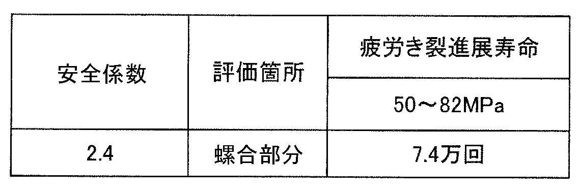
- the safety factor is 2.4 when the pressure-accumulating container 90 is used in the stress range shown in Table 1 below.
- the safety factor is a value calculated by “tensile strength of steel material constituting thin wall pipe / maximum stress occurring in thin wall pipe”.
- the magnitude of the stress (specifically, the first principal stress) generated in each thread of the screwing portion 12 is calculated by a computer Estimated by simulation. The results of this estimation are shown in Table 1 below.
- the “stress range” in Table 1 is the difference between the maximum value and the minimum value of the stress generated in each thread.
- the maximum stress generated on the first thread 12A of the cylindrical cylinder portion 1 is 842 MPa.
- the value of this maximum stress greatly exceeds the yield stress (generally 785 MPa) of high strength steels.
- the stress range in the first thread 12A is 329 MPa, which exceeds 300 MPa, which is a standard for securing the fatigue life.
- the fatigue crack growth life Na1 of the pressure accumulation container 90 of the comparative example is far below the 400,000 times required for a hydrogen storage container for a hydrogen station. Therefore, the accumulator container 90 of the comparative example has an insufficient fatigue crack growth life as this type of hydrogen storage container.
- the pressure-accumulation container 10 of this embodiment has the structure which attached the reinforcement ring 4 to the cylindrical cylinder part 1, as shown to FIG.
- the reinforcing ring 4 made of a chromium molybdenum steel material SCM 35 is used.
- the length of the reinforcing ring 4 in the axial direction of the cylindrical cylinder portion 1 is 400 mm.
- the thickness of the reinforcing ring 4 in the radial direction of the cylindrical cylinder portion 1 is 25 mm.
- FIG. 5B when the distance from the seal portion 5 to the screwing portion 12 is L, the end 4A of the reinforcing ring 4 on the pressure accumulation chamber 11 side is from the seal portion 5 to the pressure accumulation chamber 11 side.
- the end 4B opposite to the pressure accumulation chamber 11 of the reinforcing ring 4 extends to a position corresponding to the end of the screwing portion 12 (that is, the end 1E of the cylindrical portion 1).
- the coefficient of friction between the cylindrical cylinder portion 1 and the reinforcing ring 4 is 0.3.
- FIG. 5 (a) shows the stress generated in the pressure-accumulating container 10 when the internal pressure of the pressure-accumulating container 10 configured to have various dimensions shown in FIG. 5 (b) is varied between 50 MPa and 82 MPa (specifically These are figures which estimated distribution of 1st principal stress by computer simulation.
- the stress occurring at the point P (in the vicinity of the zeroth screw bottom of the cylindrical cylinder 1) shown in FIG. 5A is the largest.
- FIG. 5 (a) shows the stress generated in the pressure-accumulating container 10 when the internal pressure of the pressure-accumulating container 10 configured to have various dimensions shown in FIG. 5 (b) is varied between 50 MPa and 82 MPa (specifically These are figures which estimated distribution of 1st principal stress by computer simulation.
- the stress occurring at the point P (in the vicinity of the zeroth screw bottom of the cylindrical cylinder 1) shown in FIG. 5A is the largest.
- 6 (a) and 6 (b) show the length of the reinforcing ring 4 (specifically, the end 4A) in a state in which the end 1E of the cylindrical cylinder 1 and the end 4B of the reinforcing ring 4 are aligned.
- the stress range is reduced when the length of the reinforcing ring 4 on the side of the pressure accumulation chamber 11 is increased.
- the value of the stress range is reduced to 180 MPa, which is much smaller than the value without the reinforcing ring 4 shown in Table 1 (329 MPa).
- the fatigue crack growth life can be further improved by setting the length of the reinforcing ring 4 as shown in FIGS. 6 (a) and 6 (b).
- the optimum length of the reinforcing ring 4 is considered to be about -0.35 L from the position corresponding to the seal portion 5.
- FIGS. 7A and 7B show the case where the position of the end 4B of the reinforcing ring 4 is changed in a state where the position of the end 4A of the reinforcing ring 4 is fixed at ⁇ 0.64 L. It represents the value of stress at point P of 5 (a).
- the stress range is reduced as the position of the end 4B of the reinforcing ring 4 approaches the end 1E of the cylindrical cylinder 1, and after the position of the end 4B exceeds the end 1E, the position of the end 4B is 2.77L. It is clear that the stress range is further reduced until reaching.
- the reinforcing effect of the screwing portion 12 is improved by slightly protruding the end 4B of the reinforcing ring 4 from the end 1E of the cylindrical cylinder 1 in the opposite direction slightly from the pressure accumulation chamber 11.
- the optimal length of the reinforcing ring 4 is considered to be about 2.8 L from the position corresponding to the seal portion 5.
- the positions of the end portions 4A and 4B of the reinforcing ring 4 are set to the above-described optimum values (that is, the end portion 4A: -0.35 L, the end portion 4B: 2.8 L), the same as the pressure storage container 90 of the comparative example
- the fatigue crack growth life of the pressure accumulation container 10 became 680,000 times (the display on the graph in FIG. 4 is omitted). Therefore, compared with 74,000 times in the pressure accumulation container 90 of the comparative example shown in Table 1, the fatigue crack growth life was significantly improved. Furthermore, this fatigue crack growth life is well above the number of times of use 400,000, which is assumed as a hydrogen storage container for a hydrogen station.
- the present invention is not limited to the above embodiments, and various modifications can be adopted within the scope of the present invention.
- the present invention is not limited to the embodiments described above, and appropriate modifications, improvements, etc. are possible.
- the material, shape, size, number, arrangement location, and the like of each component in the embodiment described above are arbitrary and not limited as long as the present invention can be achieved.
- the pressure accumulation container according to the present invention can suppress both the hydrogen environment embrittlement of the screwed portion when hydrogen is contained in the pressure accumulation chamber and the fatigue crack of the screwed portion caused by the internal pressure of the pressure accumulation chamber.
- the pressure accumulation container according to the present invention having this effect can be used, for example, as a container for storing hydrogen at a hydrogen station.
Landscapes
- Engineering & Computer Science (AREA)
- Mechanical Engineering (AREA)
- General Engineering & Computer Science (AREA)
- Filling Or Discharging Of Gas Storage Vessels (AREA)
- Supply Devices, Intensifiers, Converters, And Telemotors (AREA)
- Pressure Vessels And Lids Thereof (AREA)
Abstract
Description
内部に蓄圧室を画成するシリンダ部と、
前記シリンダ部の両端部のうちの少なくとも一方の内側に配置されるねじ込み部であって、前記シリンダ部の内周部分と当該ねじ込み部の外周部分とが螺合される、ねじ込み部と、
前記ねじ込み部よりも前記蓄圧室に近い位置に配置され、前記蓄圧室に面する受圧面を有する蓋部と、
前記シリンダ部の外周面に嵌め合わされる補強リングであって、前記シリンダ部と前記ねじ込み部との螺合部分の一部又は全部に対応する前記外周面上の部分を前記シリンダ部の軸方向に沿って覆う、補強リングと、を備える。
当該蓄圧容器は、
前記蓋部と前記シリンダ部との間の隙間を封止するシール部を、更に備え、
前記補強リングは、
前記軸方向における当該補強リングの前記蓄圧室側の端部が、前記シール部に対応する前記外周面上の位置にある、又は、前記シール部に対応する前記外周面上の位置よりも前記軸方向において前記蓄圧室側の位置にある、ように構成される。
前記補強リングは、
前記軸方向における当該補強リングの前記蓄圧室とは逆側の端部が、前記螺合部分の前記蓄圧室とは逆側の端部に対応する前記外周面上の位置にある、又は、前記螺合部分の前記蓄圧室とは逆側の端部に対応する前記外周面上の位置よりも前記軸方向において前記蓄圧室から離れた位置にある、ように構成される。
当該蓄圧容器は、
前記蓄圧室内の圧力が82MPa以下50MPa以上の範囲内にて変動した場合における、前記螺合部分に生じる応力の最大値と最小値との差が300MPa以下である、ように構成される。
前記補強リングは、
前記シリンダ部を締め付けるように圧縮応力を及ぼしている状態で前記シリンダ部に嵌め合わされる。
前記シリンダ部の径方向における前記補強リングの厚さが、前記シリンダ部の外径の5%以上10%以下である。
前記蓋部は、前記シリンダ部の径方向外側に広がる延材部を有し、
前記ねじ込み部は、前記径方向外側にくぼむ窪み部を有し、
前記延材部と前記窪み部とが前記軸方向において当接し、
前記ねじ込み部の前記蓄圧室側の前記外周縁と前記蓋部とが前記軸方向において離れる、ように構成される。
前記シリンダ部は、直筒かつ円筒状の形状を有する。
日本国高圧ガス保安協会が定める超高圧ガス設備に関する基準KHKS0220(2010)に準じた疲労亀裂進展解析において、初期想定亀裂として0.1mm深さの環状亀裂を前記シリンダ部の前記螺合部分に想定した場合、40万回以上の疲労亀裂寿命を有する、ように構成される。
以下に、本発明の一実施形態に係る蓄圧容器10について説明する。
図1に示すように、本実施形態の蓄圧容器10は、内部に蓄圧室11を画成する鋼製の円筒シリンダ部1と、円筒シリンダ部1の両端部を閉じるように設けられるとともに通気穴25Dを有する金属製の蓋部2と、蓋部2を円筒シリンダ部1に固定する金属製のねじ込み部3と、円筒シリンダ部1の両端部の外周面1Fに嵌め合わさる金属製の補強リング4と、を有している。後述するように、蓋部2の蓄圧室11に向かう受圧面2Aは、蓄圧室11内の高圧ガスの圧力を直接的に受ける。一方、ねじ込み部3は、蓋部2により、蓄圧室11内のガスから隔離されている。蓄圧容器10は、例えば、水素ガスを貯蔵するために用いられ得る。
本実施形態の蓄圧容器10と、補強リング4を使用していない比較例としての蓄圧容器90との効果を比較するための試験を行った。補強リング4を使用していない蓄圧容器90の断面図を、図3に示す。蓄圧容器90は、補強リング4を有していない点を除き、上述した実施形態(例えば、図2を参照)の蓄圧容器10と同様の構成を有している。よって、蓄圧容器90が有する各部材の説明は省略する。

1A 主内面
1B 穴部
1C 雌ネジ部
1D 境界部
2 蓋部
2A 受圧面
3 ねじ込み部
4 補強リング
5 シール部
10 蓄圧容器
11 蓄圧室
12 螺合部分
20 大径部
22 延材部
23 第2軸部
30 雄ネジ部
31 貫通孔
32 窪み部
Claims (9)
- 内部に蓄圧室を画成するシリンダ部と、
前記シリンダ部の両端部のうちの少なくとも一方の内側に配置されるねじ込み部であって、前記シリンダ部の内周部分と当該ねじ込み部の外周部分とが螺合される、ねじ込み部と、
前記ねじ込み部よりも前記蓄圧室に近い位置に配置され、前記蓄圧室に面する受圧面を有する蓋部と、
前記シリンダ部の外周面に嵌め合わされる補強リングであって、前記シリンダ部と前記ねじ込み部との螺合部分の一部又は全部に対応する前記外周面上の部分を前記シリンダ部の軸方向に沿って覆う、補強リングと、を備える、
蓄圧容器。 - 請求項1に記載の蓄圧容器であって、
前記蓋部と前記シリンダ部との間の隙間を封止するシール部を、更に備え、
前記補強リングは、
前記軸方向における当該補強リングの前記蓄圧室側の端部が、前記シール部に対応する前記外周面上の位置にある、又は、前記シール部に対応する前記外周面上の位置よりも前記軸方向において前記蓄圧室側の位置にある、ように構成される、
蓄圧容器。 - 請求項1又は請求項2に記載の蓄圧容器において、
前記補強リングは、
前記軸方向における当該補強リングの前記蓄圧室とは逆側の端部が、前記螺合部分の前記蓄圧室とは逆側の端部に対応する前記外周面上の位置にある、又は、前記螺合部分の前記蓄圧室とは逆側の端部に対応する前記外周面上の位置よりも前記軸方向において前記蓄圧室から離れた位置にある、ように構成される、
蓄圧容器。 - 請求項1~請求項3の何れか一項に記載の蓄圧容器において、
前記蓄圧室内の圧力が82MPa以下50MPa以上の範囲内にて変動した場合における、前記螺合部分に生じる応力の最大値と最小値との差が300MPa以下である、ように構成される、
蓄圧容器。 - 請求項1~請求項4の何れか一項に記載の蓄圧容器において、
前記補強リングは、
前記シリンダ部を締め付けるように圧縮応力を及ぼしている状態で前記シリンダ部に嵌め合わされる、
蓄圧容器。 - 請求項1~請求項5の何れか一項に記載の蓄圧容器において、
前記シリンダ部の径方向における前記補強リングの厚さが、前記シリンダ部の外径の5%以上10%以下である、
蓄圧容器。 - 請求項1~請求項6の何れか一項に記載の蓄圧容器において、
前記蓋部は、前記シリンダ部の径方向外側に広がる延材部を有し、
前記ねじ込み部は、前記径方向外側にくぼむ窪み部を有し、
前記延材部と前記窪み部とが前記軸方向において当接し、
前記ねじ込み部の前記蓄圧室側の前記外周縁と前記蓋部とが前記軸方向において離れる、ように構成される、
蓄圧容器。 - 請求項1~請求項7の何れか一項に記載の蓄圧容器において、
前記シリンダ部は、直筒かつ円筒状の形状を有する、
蓄圧容器。 - 請求項1~請求項8の何れか一項に記載の蓄圧容器において、
日本国高圧ガス保安協会が定める超高圧ガス設備に関する基準KHKS0220(2010)に準じた疲労亀裂進展解析において、初期想定亀裂として0.1mm深さの環状亀裂を前記シリンダ部の前記螺合部分に想定した場合、40万回以上の疲労亀裂寿命を有する、ように構成される、
蓄圧容器。
Priority Applications (5)
| Application Number | Priority Date | Filing Date | Title |
|---|---|---|---|
| KR1020207015060A KR102452119B1 (ko) | 2017-10-27 | 2018-10-26 | 압력 용기 |
| CA3083552A CA3083552A1 (en) | 2017-10-27 | 2018-10-26 | Pressure vessel |
| EP18870904.2A EP3702660B1 (en) | 2017-10-27 | 2018-10-26 | Pressure vessel |
| US16/759,148 US11543079B2 (en) | 2017-10-27 | 2018-10-26 | Pressure vessel |
| CN201880076413.4A CN111433507A (zh) | 2017-10-27 | 2018-10-26 | 压力容器 |
Applications Claiming Priority (2)
| Application Number | Priority Date | Filing Date | Title |
|---|---|---|---|
| JP2017208590A JP7479622B2 (ja) | 2017-10-27 | 2017-10-27 | 蓄圧容器 |
| JP2017-208590 | 2017-10-27 |
Publications (1)
| Publication Number | Publication Date |
|---|---|
| WO2019083047A1 true WO2019083047A1 (ja) | 2019-05-02 |
Family
ID=66246970
Family Applications (1)
| Application Number | Title | Priority Date | Filing Date |
|---|---|---|---|
| PCT/JP2018/040001 Ceased WO2019083047A1 (ja) | 2017-10-27 | 2018-10-26 | 蓄圧容器 |
Country Status (7)
| Country | Link |
|---|---|
| US (1) | US11543079B2 (ja) |
| EP (1) | EP3702660B1 (ja) |
| JP (1) | JP7479622B2 (ja) |
| KR (1) | KR102452119B1 (ja) |
| CN (1) | CN111433507A (ja) |
| CA (1) | CA3083552A1 (ja) |
| WO (1) | WO2019083047A1 (ja) |
Cited By (3)
| Publication number | Priority date | Publication date | Assignee | Title |
|---|---|---|---|---|
| EP3763991A1 (en) * | 2019-07-12 | 2021-01-13 | Il Sung Machinery Co., Ltd. | Pressure vessel for storing high pressure gas |
| WO2022168737A1 (ja) * | 2021-02-03 | 2022-08-11 | Jfeスチール株式会社 | 高圧水素容器 |
| RU2811853C1 (ru) * | 2021-02-03 | 2024-01-18 | ДжФЕ СТИЛ КОРПОРЕЙШН | Водородный резервуар высокого давления |
Families Citing this family (5)
| Publication number | Priority date | Publication date | Assignee | Title |
|---|---|---|---|---|
| US11262025B2 (en) * | 2019-11-06 | 2022-03-01 | Robert Bosch Gmbh | Hydrogen gas storage tank |
| US12429167B2 (en) * | 2020-11-10 | 2025-09-30 | Jfe Steel Corporation | High pressure gas container and production method therefor |
| US20240035593A1 (en) * | 2020-11-10 | 2024-02-01 | Jfe Steel Corporation | Threaded steel pipe or tube and production method therefor |
| KR102935358B1 (ko) | 2021-06-10 | 2026-03-09 | 제이에프이 스틸 가부시키가이샤 | 축압기 |
| JP2026010489A (ja) * | 2024-07-09 | 2026-01-22 | 横浜ゴム株式会社 | 樹脂製のサイレンサの製造方法 |
Citations (5)
| Publication number | Priority date | Publication date | Assignee | Title |
|---|---|---|---|---|
| JPS62183199U (ja) * | 1986-05-14 | 1987-11-20 | ||
| JP2015158243A (ja) * | 2014-02-24 | 2015-09-03 | 株式会社日本製鋼所 | 水素ガス蓄圧器 |
| US20150362130A1 (en) * | 2013-02-08 | 2015-12-17 | Rehau Ag+Co | Device for storing and delivery of a liquid and/or gaseous medium under pressure, as well as a fuel energy conversion device and method for assembling a device for storing and delivery of a liquid and/or gaseous medium under pressure |
| JP2017141919A (ja) * | 2016-02-12 | 2017-08-17 | 株式会社日本製鋼所 | 蓄圧容器 |
| JP2017208590A (ja) | 2016-05-16 | 2017-11-24 | ブラザー工業株式会社 | 画像読取装置 |
Family Cites Families (7)
| Publication number | Priority date | Publication date | Assignee | Title |
|---|---|---|---|---|
| JPS62183199A (ja) * | 1986-02-06 | 1987-08-11 | 株式会社東芝 | プリント配線基板 |
| JPS63176897A (ja) * | 1987-01-14 | 1988-07-21 | Hitachi Ltd | 内圧を受ける円筒構造物 |
| JPS63145058U (ja) * | 1987-03-13 | 1988-09-26 | ||
| JPH0996399A (ja) | 1995-07-25 | 1997-04-08 | Toyoda Gosei Co Ltd | 圧力容器 |
| JPH10332083A (ja) | 1997-05-28 | 1998-12-15 | Mitsubishi Chem Corp | 耐圧容器 |
| JP5456889B2 (ja) * | 2010-05-19 | 2014-04-02 | 八千代工業株式会社 | 圧力容器の口金部材とブローピンとの係合構造並びにこれを有する圧力容器の口金構造および圧力容器の製造方法 |
| JP3172853U (ja) * | 2011-10-25 | 2012-01-12 | 宣行 杉村 | 2層式樹脂製アキュムレータ |
-
2017
- 2017-10-27 JP JP2017208590A patent/JP7479622B2/ja active Active
-
2018
- 2018-10-26 WO PCT/JP2018/040001 patent/WO2019083047A1/ja not_active Ceased
- 2018-10-26 US US16/759,148 patent/US11543079B2/en active Active
- 2018-10-26 CA CA3083552A patent/CA3083552A1/en active Pending
- 2018-10-26 CN CN201880076413.4A patent/CN111433507A/zh active Pending
- 2018-10-26 EP EP18870904.2A patent/EP3702660B1/en active Active
- 2018-10-26 KR KR1020207015060A patent/KR102452119B1/ko active Active
Patent Citations (5)
| Publication number | Priority date | Publication date | Assignee | Title |
|---|---|---|---|---|
| JPS62183199U (ja) * | 1986-05-14 | 1987-11-20 | ||
| US20150362130A1 (en) * | 2013-02-08 | 2015-12-17 | Rehau Ag+Co | Device for storing and delivery of a liquid and/or gaseous medium under pressure, as well as a fuel energy conversion device and method for assembling a device for storing and delivery of a liquid and/or gaseous medium under pressure |
| JP2015158243A (ja) * | 2014-02-24 | 2015-09-03 | 株式会社日本製鋼所 | 水素ガス蓄圧器 |
| JP2017141919A (ja) * | 2016-02-12 | 2017-08-17 | 株式会社日本製鋼所 | 蓄圧容器 |
| JP2017208590A (ja) | 2016-05-16 | 2017-11-24 | ブラザー工業株式会社 | 画像読取装置 |
Non-Patent Citations (3)
| Title |
|---|
| "fatigue crack propagation analysis according to Standard for Ultra High-Pressure Gas Equipment KHKS 0220", 2010, HIGH PRESSURE GAS SAFETY INSTITUTE OF JAPAN, pages: 26 |
| JOHN F. HARVEY: "Pressure Component Construction Design and Materials Application", 1980, VAN NORSTANDREINHOLD COMPANY, pages: 382 - 384 |
| See also references of EP3702660A4 |
Cited By (9)
| Publication number | Priority date | Publication date | Assignee | Title |
|---|---|---|---|---|
| EP3763991A1 (en) * | 2019-07-12 | 2021-01-13 | Il Sung Machinery Co., Ltd. | Pressure vessel for storing high pressure gas |
| WO2022168737A1 (ja) * | 2021-02-03 | 2022-08-11 | Jfeスチール株式会社 | 高圧水素容器 |
| JP2022119198A (ja) * | 2021-02-03 | 2022-08-16 | Jfeスチール株式会社 | 高圧水素容器 |
| JP7269391B2 (ja) | 2021-02-03 | 2023-05-08 | Jfeスチール株式会社 | 高圧水素容器 |
| KR20230110347A (ko) * | 2021-02-03 | 2023-07-21 | 제이에프이 스틸 가부시키가이샤 | 고압 수소 용기 |
| JP2023103269A (ja) * | 2021-02-03 | 2023-07-26 | Jfeスチール株式会社 | 高圧水素容器 |
| RU2811853C1 (ru) * | 2021-02-03 | 2024-01-18 | ДжФЕ СТИЛ КОРПОРЕЙШН | Водородный резервуар высокого давления |
| US12264778B2 (en) | 2021-02-03 | 2025-04-01 | Jfe Steel Corporation | High-pressure hydrogen container |
| KR102886985B1 (ko) | 2021-02-03 | 2025-11-17 | 제이에프이 스틸 가부시키가이샤 | 고압 수소 용기 |
Also Published As
| Publication number | Publication date |
|---|---|
| EP3702660A1 (en) | 2020-09-02 |
| JP2019082188A (ja) | 2019-05-30 |
| CN111433507A (zh) | 2020-07-17 |
| EP3702660C0 (en) | 2024-10-23 |
| KR102452119B1 (ko) | 2022-10-07 |
| CA3083552A1 (en) | 2019-05-02 |
| JP7479622B2 (ja) | 2024-05-09 |
| US11543079B2 (en) | 2023-01-03 |
| EP3702660B1 (en) | 2024-10-23 |
| US20200340625A1 (en) | 2020-10-29 |
| EP3702660A4 (en) | 2021-07-28 |
| KR20200070380A (ko) | 2020-06-17 |
Similar Documents
| Publication | Publication Date | Title |
|---|---|---|
| WO2019083047A1 (ja) | 蓄圧容器 | |
| EP3415806B1 (en) | Pressure accumulation container | |
| WO2020071088A1 (ja) | 水素蓄圧器 | |
| JP6725485B2 (ja) | 高圧水素ガス用蓄圧器 | |
| CA2954887C (en) | Pipe end fitting with venting | |
| WO2017150520A1 (ja) | 圧力容器およびフープラップ複合圧力容器 | |
| JP7530879B2 (ja) | 高圧水素ガス用蓄圧器 | |
| JP7270203B2 (ja) | ガス蓄圧器 | |
| JP2019044967A (ja) | 高圧水素ガス用蓄圧器 | |
| WO2022168737A1 (ja) | 高圧水素容器 | |
| KR102828675B1 (ko) | 고압 가스용 용기 및 그 제조 방법 | |
| JP6774465B2 (ja) | 高圧水素ガス用蓄圧器の蓋構造および高圧水素ガス用蓄圧器 | |
| US20180347527A1 (en) | Gasoline direct-injection rail | |
| JP2025104319A (ja) | 高圧水素容器 | |
| JP2020153385A (ja) | 大型異径配管フランジ | |
| WO2019026570A1 (ja) | メタルガスケット | |
| JPH0227557B2 (ja) | Yuseikanyokantsugite | |
| JPH08109913A (ja) | 耐焼き付き性に優れたバルブ取付ねじ部 |
Legal Events
| Date | Code | Title | Description |
|---|---|---|---|
| 121 | Ep: the epo has been informed by wipo that ep was designated in this application |
Ref document number: 18870904 Country of ref document: EP Kind code of ref document: A1 |
|
| NENP | Non-entry into the national phase |
Ref country code: DE |
|
| ENP | Entry into the national phase |
Ref document number: 20207015060 Country of ref document: KR Kind code of ref document: A Ref document number: 3083552 Country of ref document: CA |
|
| ENP | Entry into the national phase |
Ref document number: 2018870904 Country of ref document: EP Effective date: 20200527 |