WO2019087385A1 - 遠心圧縮機及びこの遠心圧縮機を備えたターボチャージャ - Google Patents
遠心圧縮機及びこの遠心圧縮機を備えたターボチャージャ Download PDFInfo
- Publication number
- WO2019087385A1 WO2019087385A1 PCT/JP2017/039909 JP2017039909W WO2019087385A1 WO 2019087385 A1 WO2019087385 A1 WO 2019087385A1 JP 2017039909 W JP2017039909 W JP 2017039909W WO 2019087385 A1 WO2019087385 A1 WO 2019087385A1
- Authority
- WO
- WIPO (PCT)
- Prior art keywords
- scroll
- flow path
- wall
- flow
- wall surface
- Prior art date
- Legal status (The legal status is an assumption and is not a legal conclusion. Google has not performed a legal analysis and makes no representation as to the accuracy of the status listed.)
- Ceased
Links
Images


Classifications
-
- F—MECHANICAL ENGINEERING; LIGHTING; HEATING; WEAPONS; BLASTING
- F04—POSITIVE - DISPLACEMENT MACHINES FOR LIQUIDS; PUMPS FOR LIQUIDS OR ELASTIC FLUIDS
- F04D—NON-POSITIVE-DISPLACEMENT PUMPS
- F04D17/00—Radial-flow pumps, e.g. centrifugal pumps; Helico-centrifugal pumps
- F04D17/08—Centrifugal pumps
- F04D17/10—Centrifugal pumps for compressing or evacuating
-
- F—MECHANICAL ENGINEERING; LIGHTING; HEATING; WEAPONS; BLASTING
- F04—POSITIVE - DISPLACEMENT MACHINES FOR LIQUIDS; PUMPS FOR LIQUIDS OR ELASTIC FLUIDS
- F04D—NON-POSITIVE-DISPLACEMENT PUMPS
- F04D29/00—Details, component parts, or accessories
- F04D29/40—Casings; Connections of working fluid
- F04D29/42—Casings; Connections of working fluid for radial or helico-centrifugal pumps
- F04D29/44—Fluid-guiding means, e.g. diffusers
- F04D29/441—Fluid-guiding means, e.g. diffusers especially adapted for elastic fluid pumps
-
- F—MECHANICAL ENGINEERING; LIGHTING; HEATING; WEAPONS; BLASTING
- F02—COMBUSTION ENGINES; HOT-GAS OR COMBUSTION-PRODUCT ENGINE PLANTS
- F02B—INTERNAL-COMBUSTION PISTON ENGINES; COMBUSTION ENGINES IN GENERAL
- F02B39/00—Component parts, details, or accessories relating to, driven charging or scavenging pumps, not provided for in groups F02B33/00 - F02B37/00
-
- F—MECHANICAL ENGINEERING; LIGHTING; HEATING; WEAPONS; BLASTING
- F04—POSITIVE - DISPLACEMENT MACHINES FOR LIQUIDS; PUMPS FOR LIQUIDS OR ELASTIC FLUIDS
- F04D—NON-POSITIVE-DISPLACEMENT PUMPS
- F04D29/00—Details, component parts, or accessories
- F04D29/40—Casings; Connections of working fluid
- F04D29/42—Casings; Connections of working fluid for radial or helico-centrifugal pumps
- F04D29/4206—Casings; Connections of working fluid for radial or helico-centrifugal pumps especially adapted for elastic fluid pumps
- F04D29/4226—Fan casings
- F04D29/4233—Fan casings with volutes extending mainly in axial or radially inward direction
-
- F—MECHANICAL ENGINEERING; LIGHTING; HEATING; WEAPONS; BLASTING
- F05—INDEXING SCHEMES RELATING TO ENGINES OR PUMPS IN VARIOUS SUBCLASSES OF CLASSES F01-F04
- F05D—INDEXING SCHEME FOR ASPECTS RELATING TO NON-POSITIVE-DISPLACEMENT MACHINES OR ENGINES, GAS-TURBINES OR JET-PROPULSION PLANTS
- F05D2220/00—Application
- F05D2220/40—Application in turbochargers
-
- F—MECHANICAL ENGINEERING; LIGHTING; HEATING; WEAPONS; BLASTING
- F05—INDEXING SCHEMES RELATING TO ENGINES OR PUMPS IN VARIOUS SUBCLASSES OF CLASSES F01-F04
- F05D—INDEXING SCHEME FOR ASPECTS RELATING TO NON-POSITIVE-DISPLACEMENT MACHINES OR ENGINES, GAS-TURBINES OR JET-PROPULSION PLANTS
- F05D2240/00—Components
- F05D2240/10—Stators
- F05D2240/12—Fluid guiding means, e.g. vanes
-
- F—MECHANICAL ENGINEERING; LIGHTING; HEATING; WEAPONS; BLASTING
- F05—INDEXING SCHEMES RELATING TO ENGINES OR PUMPS IN VARIOUS SUBCLASSES OF CLASSES F01-F04
- F05D—INDEXING SCHEME FOR ASPECTS RELATING TO NON-POSITIVE-DISPLACEMENT MACHINES OR ENGINES, GAS-TURBINES OR JET-PROPULSION PLANTS
- F05D2240/00—Components
- F05D2240/10—Stators
- F05D2240/14—Casings or housings protecting or supporting assemblies within
-
- F—MECHANICAL ENGINEERING; LIGHTING; HEATING; WEAPONS; BLASTING
- F05—INDEXING SCHEMES RELATING TO ENGINES OR PUMPS IN VARIOUS SUBCLASSES OF CLASSES F01-F04
- F05D—INDEXING SCHEME FOR ASPECTS RELATING TO NON-POSITIVE-DISPLACEMENT MACHINES OR ENGINES, GAS-TURBINES OR JET-PROPULSION PLANTS
- F05D2250/00—Geometry
- F05D2250/50—Inlet or outlet
- F05D2250/52—Outlet
Definitions
- the present disclosure relates to a centrifugal compressor and a turbocharger provided with the centrifugal compressor.
- At least one embodiment of the present disclosure is directed to providing a centrifugal compressor with improved efficiency at a low flow operating point and a turbocharger including the centrifugal compressor.
- a centrifugal compressor comprising an impeller and a housing, wherein
- the housing is A scroll portion in which a scroll flow passage having a spiral shape is formed on the outer peripheral side of the impeller;
- a diffuser flow that includes a pair of flow passage walls provided at intervals in a direction in which the rotational axis of the impeller extends, and communicates with the scroll flow passage along a circumferential direction of the scroll flow passage radially inside the impeller And a diffuser portion forming a passage between the pair of flow passage walls,
- the pair of flow path walls are A first flow path wall, And a second flow path wall positioned on the scroll center side of the scroll flow path with respect to the first flow path wall in a direction in which the rotation axis extends.
- the second flow path wall includes a portion of the inner wall surface positioned on the radially inner side of the inner wall surface of the scroll flow path, and the inner wall surface including the second flow path wall includes the rotation axis.
- At least one concave arc portion having a radius of curvature in the scroll channel in a cross section of the housing by a plane;
- the inclination angle between the tangential direction of the radially outer end edge of the impeller of the outermost concave arc portion in the radial direction of the impeller of the at least one concave arc portion and the direction perpendicular to the rotation axis is Has a distribution along the circumferential direction of the scroll channel,
- the distribution of the inclination angle is Have a minimum value or a minimum value within the range of the central angle from 30 ° to 210 °.
- the direction of the swirling flow is such that the swirling flow circulating while swirling in the scroll flow passage along the inner wall surface of the scroll flow passage makes just one round along the inner wall surface of the scroll flow passage Since the angle between the flow direction of the compressed fluid discharged from the diffuser channel and the flow direction of the compressed fluid decreases, the interference between the swirling flow and the flow of the compressed fluid discharged from the diffuser channel is suppressed, and the flow in the scroll channel is suppressed. The occurrence of peeling is reduced. As a result, the efficiency of the centrifugal compressor at the low flow rate operating point can be improved.
- the distribution of the tilt angles has local minima or minima within the range of the central angle from 30 ° to 120 °.
- the flow passage area of the scroll flow passage decreases from the outlet side toward the tongue. Due to such a shape of the scroll channel, the inclination angle of the concave arc portion tends to be larger as it is closer to the tongue. According to the configuration of the above (2), if the scroll flow path is formed without being aware of the magnitude of the tilt angle, the tilt angle tends to increase, and this tilt angle is in the range of 30 ° to 120 ° central angle
- this inclination angle can be reduced in the range of the central angle from 30 ° to 210 °, so that the swirl flow and the diffuser flow passage are discharged. Interference with the flow of compressed fluid is further suppressed, and the occurrence of separation in the scroll channel is further reduced. As a result, the efficiency of the centrifugal compressor at the low flow rate operating point can be improved.
- the second flow path wall is A flat inner wall which defines the diffuser flow path and which is flat and perpendicular to the rotation axis; A convex inner wall surface which defines the scroll channel and is convexly curved with respect to the scroll channel; At least one concave inner wall that defines the at least one concave arc portion in a cross section of the housing according to a plane that defines the scroll flow path and includes a plane of rotation, the at least one concave inner wall of the at least one concave inner wall; At least one concave inner wall surface in which the outermost concave inner wall surface in the radial direction of the impeller is connected to the convex arc portion; It includes an end face connecting the flat inner wall surface and the convex inner wall surface at the outermost side of the flat inner wall surface in the radial direction of the impeller.
- the interference between the swirling flow and the flow of the compressed fluid discharged from the diffuser flow path can be suppressed to reduce the occurrence of separation in the scroll flow path and to define the diffuser flow path
- the fact that the inner wall is flat and perpendicular to the axis of rotation can also facilitate the processing of the diffuser channel.
- the outer diameter of the diffuser flow passage around the rotation axis has a distribution in the circumferential direction of the diffuser flow passage, and the distribution of the outer diameter of the diffuser flow passage is the central angle from 30 ° to 210 °
- the maximum value or the maximum value is within the range of
- the inclination angle of the concave arc portion can be minimized or minimized in the range of the central angle from 30 ° to 210 °, the swirl flow and the compression discharged from the diffuser flow path Interference with the flow of fluid is suppressed to reduce the occurrence of separation in the scroll channel. As a result, the efficiency of the centrifugal compressor at the low flow rate operating point can be improved.
- the distance from the rotation axis to the scroll center of the scroll flow channel has a distribution in the circumferential direction of the scroll flow channel, and the distribution of the distance is minimized within the range of the central angle from 30 ° to 210 ° It has a value or a minimum value.
- the inclination angle of the concave arc portion can be minimized or minimized in the range of the central angle from 30 ° to 210 °, the swirl flow and the compression discharged from the diffuser flow path Interference with the flow of fluid is suppressed to reduce the occurrence of separation in the scroll channel. As a result, the efficiency of the centrifugal compressor at the low flow rate operating point can be improved.
- a turbocharger according to at least one embodiment of the present disclosure is: The centrifugal compressor according to any one of the above (1) to (5) is provided.
- a swirl flow circulating while swirling in the scroll flow path along the inner wall surface of the scroll flow path is around the circumference just along the inner wall surface of the scroll flow path. Since the angle between the flow direction and the flow direction of the compressed fluid discharged from the diffuser flow path is small, the interference between the swirl flow and the flow of the compressed fluid discharged from the diffuser flow path is suppressed, and the scroll flow is reduced. The occurrence of delamination in the channel is reduced. As a result, the efficiency of the centrifugal compressor at the low flow rate operating point can be improved.
- FIG. 1 is a partial cross-sectional view of a centrifugal compressor housing according to a plane including a rotational axis of the centrifugal compressor according to an embodiment of the present disclosure.
- FIG. 7 is a streamline diagram showing how compressed air discharged from a diffuser flow passage swirls along an inner wall surface of a scroll flow passage in a centrifugal compressor according to an embodiment of the present disclosure. It is a schematic diagram for demonstrating the principle which a rotational flow and the flow of the compressed air discharged
- FIG. 5 is an enlarged partial cross-sectional view of a second flow passage wall of a centrifugal compressor according to an embodiment of the present disclosure.
- centrifugal compressor according to an embodiment of the present disclosure will be described by taking a centrifugal compressor of a turbocharger as an example.
- the centrifugal compressor in the present disclosure is not limited to a centrifugal compressor of a turbocharger, and may be any centrifugal compressor operating alone.
- the fluid compressed by this compressor is air, but can be replaced by any fluid.
- the centrifugal compressor 1 includes a housing 2 and an impeller 3 rotatably provided around the rotational axis L in the housing 2.
- the housing 2 has a pair of scrolls 4 in which a scroll flow passage 5 having a spiral shape is formed on the outer peripheral side of the impeller 3 and a pair of clearances provided in the extending direction of the rotation axis L.
- It has the flow path wall 7, ie, the diffuser portion 6 including the first flow path wall 7a and the second flow path wall 7b, and the cylindrical air inlet portion 9.
- the second channel wall 7b is located on the scroll center O S side of the scroll passage 5 to the first channel wall 7a in the direction of extension of the rotation axis L.
- a diffuser flow path 8 communicating with the scroll flow path 5 is formed along the circumferential direction of the scroll flow path 5 inside the impeller 3 in the radial direction .
- the air flowing into the centrifugal compressor 1 via the air inlet 9 is compressed by the impeller 3 to be compressed air.
- the compressed air flows through the diffuser flow path 8 into the scroll flow path 5, and then flows through the scroll flow path 5 and is discharged from the centrifugal compressor 1.
- the centrifugal compressor 1 If the amount of air flowing into the centrifugal compressor 1 is small, such as when the turbocharger operates at a low speed, the centrifugal compressor 1 operates in a stall state, and the efficiency decreases. In such an operation area, occurrence of a large scale peeling is confirmed in the scroll channel 5. As a result of intensive studies, the present inventors have found one of the factors causing such exfoliation. The principle of occurrence of peeling due to the factor will be described below.
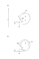
- the circumferential position in the scroll channel 5 from the tongue 4a of the scroll 4 (see FIG. 2) toward the outlet of the scroll channel 5 is taken as the rotational axis L with reference to the tongue 4a.
- a central angle ⁇ as a center. Therefore, the central angle ⁇ representing the circumferential position of the tongue 4a is 0 °.
- the flow f 1 of the compressed air discharged from the diffuser channel 8 near the tongue 4 a circulates the scroll channel 5 while turning along the inner wall surface of the scroll channel 5.
- FIG. 4A in a cross section of the housing 2 (see FIG. 2) including the rotation axis L, a tangent of a portion 5a1 of the inner wall surface 5a of the scroll flow passage 5 connected to the second flow passage wall 7b.
- a tangent of a portion 5a1 of the inner wall surface 5a of the scroll flow passage 5 connected to the second flow passage wall 7b As the inclination angle ⁇ between the direction A and the direction B perpendicular to the rotation axis L is larger, ie, closer to 90 °, as shown in FIG. 4B, along the inner wall surface 5a of the scroll passage 5 a turning flow f 2 of the compressed air flowing through Te, the angle ⁇ between the flow f 3 of the compressed air discharged from the diffuser flow path 8 is increased. Then, to avoid interference to the flow f 3 of the compressed air tends to flow from the diffuser flow path 8 to the scroll flow path 5 is turning flow f 2 closes, so that peeling at the portion where the interference occurs occurs.
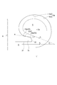
- the second flow path wall 7b delimits the diffuser flow path 8 and is connected to the flat inner wall 21 which is flat and perpendicular to the rotation axis L and the most radially outer side of the flat inner wall 21 vertically to the flat inner wall 21
- a concave inner wall 24 which is curved.
- the inner wall surface 5a of the scroll passage 5 the virtual line L' parallel virtual line L the scroll center O S as the rotation axis L radially inner portion 5a2 and radially outward with respect to It distinguishes with the part 5a3 of.
- the end surface 22, the convex inner wall surface 23 and the concave inner wall surface 24 are a part of the portion 5 a 2 of the inner wall surface 5 a.
- the center of curvature of the convex arc portion 23a formed by the convex inner wall surface 23 Curving in a concave shape with respect to the scroll flow path 5 means positioning outside the flow path 5 means that the curvature of the concave arc portion 24 a formed by the concave inner wall surface 24 in the cross section of the housing 2 including the rotation axis L It means that the center is located inside the scroll channel 5.
- the present inventors obtained the result that peeling tends to occur in the range of central angle ⁇ from 30 ° to 210 ° by performing CFD analysis. This is because when the stable swirling flow is formed in the scroll flow passage 5, the swirling flow in the scroll flow passage 5 and the flow of the compressed air discharged from the diffuser flow passage 8 will not gradually interfere with each other. Such interference is likely to occur toward the upstream side of the scroll channel 5. Therefore, the occurrence of peeling can be effectively reduced by setting the cross-sectional shape of the scroll channel 5 to a shape such that the inclination angle ⁇ becomes smaller on the upstream side.
- the cross-sectional shape of the scroll passage 5 shown in FIG. 5 is a shape in one cross section of the housing 2 (see FIG. 2).
- the cross-sectional shape of the scroll channel 5 actually changes in the circumferential direction. Therefore, the inclination angle ⁇ changes in the circumferential direction. That is, the inclination angle ⁇ has a distribution along the circumferential direction of the scroll channel 5. Therefore, as shown in FIG. 6, according to the above knowledge obtained by the present inventor, in the range of the circumferential direction position of the scroll channel 5 in which the central angle ⁇ is in the range of 30 ° to 210 °, With the distribution having the minimum value, the occurrence of peeling can be effectively reduced.
- the distribution of the inclination angle ⁇ does not have the minimum value in the above range, but is a distribution having the minimum value in the range of the central angle ⁇ of 30 ° to 210 °, that is, the minimum value. Good. In other words, the distribution of the inclination angle ⁇ may have a value smaller than the minimum value within the range of the central angle ⁇ of 210 ° or later.
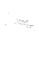
- the outer diameter of the diffuser flow passage 8 (see FIG. 1) is locally increased in the circumferential direction. That is, the distribution in the circumferential direction of the outer diameter of the diffuser flow passage 8 is made to have a maximum value or a maximum value within the range of the central angle ⁇ of 30 ° to 210 °.
- the position of the end face 22 of the second flow passage wall 7 b is positioned more radially outward than the other portions. ing. Then, since the radial width of the concave inner wall surface 24 can be increased, the inclination of the tangential direction A of the portion 5a1 becomes closer to the horizontal direction, and the inclination angle ⁇ becomes smaller.
- FIG. 7 shows a graph representing the distribution of the outer diameter of the diffuser flow passage 8 in the circumferential direction and a graph representing the distribution of the inclination angle ⁇ in that case.
- the distribution in the circumferential direction of the distance R is made to have a minimum value or a minimum value within the range of the central angle ⁇ of 30 ° to 210 °.
- the cross section of the scroll passage 5 is positioned radially inward compared with the other portions although the position of the outlet of the diffuser passage 8 is the same. It is supposed to Then, since the inclination of the tangential direction A of the portion 5a1 becomes closer to the horizontal direction, the inclination angle ⁇ becomes smaller.
- FIG. 8 shows a graph representing the distribution of the distance R in the circumferential direction and a graph representing the distribution of the inclination angle ⁇ in that case.
- the distance from the axis of rotation L to scroll center O S of the scroll passage 5 R ( Combining FIG. 2) with locally reducing in the circumferential direction. If each of them is performed alone, the outer diameter of the diffuser flow passage 8 becomes locally large or the distance R becomes locally small, which makes manufacturing difficult and adversely affects the flow of compressed air. There is a possibility of giving. However, by combining the two, it is possible to moderate local changes in the outer diameter of the diffuser flow passage 8 and the distance R.
- the second flow path wall 7 b is connected to the flat end face 22 vertically connected to the flat inner wall surface 21 and the end face 22 and has a convex shape curved in a convex shape with respect to the scroll flow path 5.
- the inner wall surface 23 and the concave inner wall surface 24 which is connected to the convex inner wall surface 23 and is concavely curved with respect to the scroll passage 5 are provided, but the present invention is not limited to this configuration.
- the end face 22 may not be perpendicular to the flat inner wall 21 or may be curved rather than flat. Further, the concave inner wall surface 24 and the end surface 22 may be connected without the convex inner wall surface 23.
- FIG. 9 exemplarily shows the case where the concave inner wall 24 includes two concave inner walls.
- the two concave inner wall surfaces constitute a first concave circular arc portion 241 and a second concave circular arc portion 242, respectively.
- the second concave arc portion 242 has a radially inner end 242a and a radially outer end 242b, the end 242a is connected to the first concave arc portion 241, and the end 242b is a convex arc portion 23a. It is connected to the.
- the inclination angle ⁇ is perpendicular to the tangential direction A of the radially outer end 242 b of the concave arc portion located outermost in the radial direction, ie, the second concave arc portion 242, and the rotation axis L It is the angle that makes with the direction B.
- the distribution of the inclination angle ⁇ has the minimum value or the minimum value in the range of the central angle ⁇ from 30 ° to 210 °, but the range of the central angle ⁇ from 30 ° to 120 ° It may have a local minimum or a minimum (see FIG. 6).
- the flow passage area of the scroll flow passage 5 decreases from the outlet side toward the tongue 4 a. Due to such a shape of the scroll channel 5, the inclination angle ⁇ (see FIG. 5) of the concave arc portion 24a (see FIG. 5) tends to be larger as it is closer to the tongue 4a.
- the inclination angle ⁇ has a minimum value or a minimum value in the range of a central angle from 30 ° to 120 ° where the inclination angle ⁇ tends to increase.
- the inclination angle ⁇ can be reduced in the range of the central angle from 30 ° to 210 °, so that the swirl flow f 2 and the diffuser channel 8 are discharged. is further suppressed interference with the flow f 3 of the compressed fluid, the occurrence of peeling in the scroll passage 8 is further reduced. As a result, the efficiency of the centrifugal compressor 1 at the small flow rate operating point can be improved.
- the diffuser flow passage 8 is usually formed by cutting
- the diffuser inner flow passage 21 is defined by the flat inner wall surface 21 defining the diffuser flow passage 8 being perpendicular to the rotation axis L and flat. Can be easily processed.
Landscapes
- Engineering & Computer Science (AREA)
- Mechanical Engineering (AREA)
- General Engineering & Computer Science (AREA)
- Chemical & Material Sciences (AREA)
- Combustion & Propulsion (AREA)
- Structures Of Non-Positive Displacement Pumps (AREA)
- Supercharger (AREA)
Abstract
Description
インペラ及びハウジングを備える遠心圧縮機であって、
前記ハウジングは、
前記インペラの外周側に渦巻き状のスクロール流路が形成されたスクロール部と、
前記インペラの回転軸線の延びる方向に間隔をあけて設けられた一対の流路壁を含み、前記インペラの半径方向内側で前記スクロール流路の周方向に沿って前記スクロール流路と連通するディフューザ流路を前記一対の流路壁間に形成するディフューザ部と
を含み、
前記一対の流路壁は、
第1流路壁と、
前記回転軸線の延びる方向において前記第1流路壁に対して前記スクロール流路のスクロール中心側に位置する第2流路壁と
を有し、
前記第2流路壁は、前記スクロール流路の内壁面のうち前記半径方向内側に位置する内壁面の一部を含み、前記第2流路壁が含む前記内壁面は、前記回転軸線を含む平面による前記ハウジングの断面において、前記スクロール流路内に曲率半径を有する少なくとも1つの凹状円弧部分を構成し、
前記少なくとも1つの凹状円弧部分のうち前記インペラの半径方向において最も外側の凹状円弧部分の前記インペラの半径方向外側の端縁の接線方向と、前記回転軸線と垂直な方向とのなす傾斜角度は、前記スクロール流路の周方向に沿って分布を有し、
前記スクロール部の舌部から前記スクロール流路の出口に向かう前記スクロール流路内の周方向位置を前記舌部を基準として前記回転軸線を中心とする中心角で表すと、前記傾斜角度の前記分布は、30°から210°までの前記中心角の範囲内に極小値又は最小値を有する。
前記傾斜角度の前記分布は、30°から120°までの前記中心角の範囲内に極小値又は最小値を有する。
前記第2流路壁は、
前記ディフューザ流路を画定するとともに前記回転軸線と垂直かつ平坦な平坦内壁面と、
前記スクロール流路を画定するとともに前記スクロール流路に対して凸状に湾曲した凸状内壁面と、
前記スクロール流路を画定するとともに前記回転軸線を含む平面による前記ハウジングの断面において前記少なくとも1つの凹状円弧部分を構成する少なくとも1つの凹状内壁面であって、該少なくとも1つの凹状内壁面のうち前記インペラの半径方向において最も外側の凹状内壁面が前記凸状円弧部分に接続される少なくとも1つの凹状内壁面と、
前記インペラの半径方向において前記平坦内壁面の最も外側で前記平坦内壁面と前記凸状内壁面とを接続する端面と
を含む。
前記回転軸線を中心とする前記ディフューザ流路の外径は前記ディフューザ流路の周方向に分布を有し、前記ディフューザ流路の外径の前記分布は、30°から210°までの前記中心角の範囲内に極大値又は最大値を有する。
前記回転軸線から前記スクロール流路のスクロール中心までの距離は前記スクロール流路の周方向に分布を有し、前記距離の前記分布は、30°から210°までの前記中心角の範囲内に極小値又は最小値を有する。
上記(1)~(5)のいずれかの遠心圧縮機を備える。
2 ハウジング
3 インペラ
4 スクロール部
4a 舌部
5 スクロール流路
5a (スクロール流路の)内壁面
5a1 (内壁面の)部分
5a2 (内壁面の)半径方向内側の部分
5a3 (内壁面の)半径方向外側の部分
6 ディフューザ部
7 流路壁
7a 第1流路壁
7b 第2流路壁
8 ディフューザ流路
9 空気入口部
21 平坦内壁面
22 端面
23 凸状内壁面
23a 凸状円弧部分
24 凹状内壁面
24a 凹状円弧部分
24a1 (凹状円弧部分の)端縁
241 第1凹状円弧部分
242 第2凹状円弧部分
242a (第2凹状円弧部分の)端縁
242b (第2凹状円弧部分の)端縁
A 接線方向
B 回転軸線と垂直な方向
L (インペラの)回転軸線
L’ 仮想線
Os スクロール中心
α 傾斜角度
β 角度
θ 中心角
f1 舌部付近でディフューザ流路から排出される圧縮空気の流れ
f2 旋回流れ
f3 ディフューザ流路から排出される圧縮空気の流れ
Claims (6)
- インペラ及びハウジングを備える遠心圧縮機であって、
前記ハウジングは、
前記インペラの外周側に渦巻き状のスクロール流路が形成されたスクロール部と、
前記インペラの回転軸線の延びる方向に間隔をあけて設けられた一対の流路壁を含み、前記インペラの半径方向内側で前記スクロール流路の周方向に沿って前記スクロール流路と連通するディフューザ流路を前記一対の流路壁間に形成するディフューザ部と
を含み、
前記一対の流路壁は、
第1流路壁と、
前記回転軸線の延びる方向において前記第1流路壁に対して前記スクロール流路のスクロール中心側に位置する第2流路壁と
を有し、
前記第2流路壁は、前記スクロール流路の内壁面のうち前記半径方向内側に位置する内壁面の一部を含み、前記第2流路壁が含む前記内壁面は、前記回転軸線を含む平面による前記ハウジングの断面において、前記スクロール流路内に曲率半径を有する少なくとも1つの凹状円弧部分を構成し、
前記少なくとも1つの凹状円弧部分のうち前記インペラの半径方向において最も外側の凹状円弧部分の前記インペラの半径方向外側の端縁の接線方向と、前記回転軸線と垂直な方向とのなす傾斜角度は、前記スクロール流路の周方向に沿って分布を有し、
前記スクロール部の舌部から前記スクロール流路の出口に向かう前記スクロール流路内の周方向位置を前記舌部を基準として前記回転軸線を中心とする中心角で表すと、前記傾斜角度の前記分布は、30°から210°までの前記中心角の範囲内に極小値又は最小値を有する遠心圧縮機。 - 前記傾斜角度の前記分布は、30°から120°までの前記中心角の範囲内に極小値又は最小値を有する、請求項1に記載の遠心圧縮機。
- 前記第2流路壁は、
前記ディフューザ流路を画定するとともに前記回転軸線と垂直かつ平坦な平坦内壁面と、
前記スクロール流路を画定するとともに前記スクロール流路に対して凸状に湾曲した凸状内壁面と、
前記スクロール流路を画定するとともに前記回転軸線を含む平面による前記ハウジングの断面において前記少なくとも1つの凹状円弧部分を構成する少なくとも1つの凹状内壁面であって、該少なくとも1つの凹状内壁面のうち前記インペラの半径方向において最も外側の凹状内壁面が前記凸状円弧部分に接続される少なくとも1つの凹状内壁面と、
前記インペラの半径方向において前記平坦内壁面の最も外側で前記平坦内壁面と前記凸状内壁面とを接続する端面と
を含む、請求項1または2に記載の遠心圧縮機。 - 前記回転軸線を中心とする前記ディフューザ流路の外径は前記ディフューザ流路の周方向に分布を有し、前記ディフューザ流路の外径の前記分布は、30°から210°までの前記中心角の範囲内に極大値又は最大値を有する、請求項1~3のいずれか一項に記載の遠心圧縮機。
- 前記回転軸線から前記スクロール流路のスクロール中心までの距離は前記スクロール流路の周方向に分布を有し、前記距離の前記分布は、30°から210°までの前記中心角の範囲内に極小値又は最小値を有する、請求項1~4のいずれか一項に記載の遠心圧縮機。
- 請求項1~5のいずれか一項に記載の遠心圧縮機を備えたターボチャージャ。
Priority Applications (5)
| Application Number | Priority Date | Filing Date | Title |
|---|---|---|---|
| EP17930425.8A EP3708848B1 (en) | 2017-11-06 | 2017-11-06 | Centrifugal compressor and turbocharger comprising said centrifugal compressor |
| CN201780090061.3A CN110573748B (zh) | 2017-11-06 | 2017-11-06 | 离心压缩机以及具备该离心压缩机的涡轮增压器 |
| PCT/JP2017/039909 WO2019087385A1 (ja) | 2017-11-06 | 2017-11-06 | 遠心圧縮機及びこの遠心圧縮機を備えたターボチャージャ |
| US16/605,454 US11073164B2 (en) | 2017-11-06 | 2017-11-06 | Centrifugal compressor and turbocharger including the same |
| JP2019550120A JP6842564B2 (ja) | 2017-11-06 | 2017-11-06 | 遠心圧縮機及びこの遠心圧縮機を備えたターボチャージャ |
Applications Claiming Priority (1)
| Application Number | Priority Date | Filing Date | Title |
|---|---|---|---|
| PCT/JP2017/039909 WO2019087385A1 (ja) | 2017-11-06 | 2017-11-06 | 遠心圧縮機及びこの遠心圧縮機を備えたターボチャージャ |
Publications (1)
| Publication Number | Publication Date |
|---|---|
| WO2019087385A1 true WO2019087385A1 (ja) | 2019-05-09 |
Family
ID=66331524
Family Applications (1)
| Application Number | Title | Priority Date | Filing Date |
|---|---|---|---|
| PCT/JP2017/039909 Ceased WO2019087385A1 (ja) | 2017-11-06 | 2017-11-06 | 遠心圧縮機及びこの遠心圧縮機を備えたターボチャージャ |
Country Status (5)
| Country | Link |
|---|---|
| US (1) | US11073164B2 (ja) |
| EP (1) | EP3708848B1 (ja) |
| JP (1) | JP6842564B2 (ja) |
| CN (1) | CN110573748B (ja) |
| WO (1) | WO2019087385A1 (ja) |
Cited By (1)
| Publication number | Priority date | Publication date | Assignee | Title |
|---|---|---|---|---|
| JPWO2020240775A1 (ja) * | 2019-05-30 | 2020-12-03 |
Families Citing this family (6)
| Publication number | Priority date | Publication date | Assignee | Title |
|---|---|---|---|---|
| JP7413514B2 (ja) * | 2020-04-17 | 2024-01-15 | 三菱重工エンジン&ターボチャージャ株式会社 | スクロールケーシングおよび遠心圧縮機 |
| DE112020006913T5 (de) * | 2020-05-21 | 2023-01-19 | Mitsubishi Heavy Industries Engine & Turbocharger, Ltd. | Schneckengehäuse und zentrifugalverdichter |
| CN116057265B (zh) * | 2020-12-09 | 2025-07-25 | 株式会社Ihi | 离心压缩机及增压器 |
| CN114857088B (zh) * | 2022-05-30 | 2024-06-25 | 杭州老板电器股份有限公司 | 一种吸油烟机 |
| US20240355437A1 (en) * | 2023-04-21 | 2024-10-24 | Matrixcare, Inc. | Machine learning-based summarization and evaluation of clinical data |
| CN120281415A (zh) * | 2024-01-08 | 2025-07-08 | 宁波环球广电科技有限公司 | 参数调整方法及系统 |
Citations (5)
| Publication number | Priority date | Publication date | Assignee | Title |
|---|---|---|---|---|
| JP2010216378A (ja) * | 2009-03-17 | 2010-09-30 | Kobe Steel Ltd | ターボ圧縮機 |
| WO2012090853A1 (ja) * | 2010-12-27 | 2012-07-05 | 三菱重工業株式会社 | 遠心圧縮機のスクロール構造 |
| JP2012193716A (ja) * | 2011-03-17 | 2012-10-11 | Mitsubishi Heavy Ind Ltd | 遠心圧縮機のスクロール構造 |
| JP2016017419A (ja) * | 2014-07-07 | 2016-02-01 | トヨタ自動車株式会社 | 過給機 |
| WO2017109949A1 (ja) | 2015-12-25 | 2017-06-29 | 三菱重工業株式会社 | 遠心圧縮機及びターボチャージャ |
Family Cites Families (5)
| Publication number | Priority date | Publication date | Assignee | Title |
|---|---|---|---|---|
| JP2005188337A (ja) * | 2003-12-25 | 2005-07-14 | Toyota Motor Corp | 作動流体還流路を有する過給用コンプレッサ |
| DE102007034236A1 (de) | 2007-07-23 | 2009-02-05 | Continental Automotive Gmbh | Radialverdichter mit einem Diffusor für den Einsatz bei einem Turbolader |
| JP5479316B2 (ja) * | 2010-12-28 | 2014-04-23 | 三菱重工業株式会社 | 遠心圧縮機のスクロール構造 |
| JP5439423B2 (ja) * | 2011-03-25 | 2014-03-12 | 三菱重工業株式会社 | 遠心圧縮機のスクロール形状 |
| DE112016005630T5 (de) * | 2015-12-10 | 2018-08-30 | Ihi Corporation | Ausstosspartie für einen radialverdichter |
-
2017
- 2017-11-06 US US16/605,454 patent/US11073164B2/en active Active
- 2017-11-06 WO PCT/JP2017/039909 patent/WO2019087385A1/ja not_active Ceased
- 2017-11-06 EP EP17930425.8A patent/EP3708848B1/en active Active
- 2017-11-06 JP JP2019550120A patent/JP6842564B2/ja active Active
- 2017-11-06 CN CN201780090061.3A patent/CN110573748B/zh active Active
Patent Citations (5)
| Publication number | Priority date | Publication date | Assignee | Title |
|---|---|---|---|---|
| JP2010216378A (ja) * | 2009-03-17 | 2010-09-30 | Kobe Steel Ltd | ターボ圧縮機 |
| WO2012090853A1 (ja) * | 2010-12-27 | 2012-07-05 | 三菱重工業株式会社 | 遠心圧縮機のスクロール構造 |
| JP2012193716A (ja) * | 2011-03-17 | 2012-10-11 | Mitsubishi Heavy Ind Ltd | 遠心圧縮機のスクロール構造 |
| JP2016017419A (ja) * | 2014-07-07 | 2016-02-01 | トヨタ自動車株式会社 | 過給機 |
| WO2017109949A1 (ja) | 2015-12-25 | 2017-06-29 | 三菱重工業株式会社 | 遠心圧縮機及びターボチャージャ |
Non-Patent Citations (1)
| Title |
|---|
| See also references of EP3708848A4 |
Cited By (4)
| Publication number | Priority date | Publication date | Assignee | Title |
|---|---|---|---|---|
| JPWO2020240775A1 (ja) * | 2019-05-30 | 2020-12-03 | ||
| WO2020240775A1 (ja) * | 2019-05-30 | 2020-12-03 | 三菱重工エンジン&ターボチャージャ株式会社 | 遠心圧縮機及びターボチャージャ |
| JP7138242B2 (ja) | 2019-05-30 | 2022-09-15 | 三菱重工エンジン&ターボチャージャ株式会社 | 遠心圧縮機及びターボチャージャ |
| US11795969B2 (en) | 2019-05-30 | 2023-10-24 | Mitsubishi Heavy Industries Engine & Turbocharger, Ltd. | Centrifugal compressor and turbocharger |
Also Published As
| Publication number | Publication date |
|---|---|
| JPWO2019087385A1 (ja) | 2020-04-23 |
| EP3708848A4 (en) | 2021-07-07 |
| US20210123456A1 (en) | 2021-04-29 |
| JP6842564B2 (ja) | 2021-03-17 |
| EP3708848B1 (en) | 2025-05-07 |
| CN110573748A (zh) | 2019-12-13 |
| CN110573748B (zh) | 2021-06-01 |
| EP3708848A1 (en) | 2020-09-16 |
| US11073164B2 (en) | 2021-07-27 |
Similar Documents
| Publication | Publication Date | Title |
|---|---|---|
| JP6842564B2 (ja) | 遠心圧縮機及びこの遠心圧縮機を備えたターボチャージャ | |
| CN110234887B (zh) | 离心压缩机及涡轮增压器 | |
| US20100098548A1 (en) | Mixed Flow Turbine or Radial Turbine | |
| JP7082948B2 (ja) | 遠心圧縮機、ターボチャージャ | |
| WO2011013258A1 (ja) | 遠心圧縮機のインペラ | |
| US10788045B2 (en) | Discharge section structure for centrifugal compressor | |
| US12460562B2 (en) | Mixed flow turbine and turbocharger | |
| US20180347382A1 (en) | Centrifugal compressor and turbocharger | |
| WO2012124388A1 (ja) | 遠心圧縮機のスクロール構造 | |
| EP3299635B1 (en) | Scroll casing and centrifugal compressor | |
| JP2008075536A (ja) | 遠心圧縮機 | |
| US11835058B2 (en) | Impeller and centrifugal compressor | |
| US11209015B2 (en) | Centrifugal compressor | |
| CN108700090B (zh) | 压缩机涡旋及离心压缩机 | |
| US20210003145A1 (en) | Multi-stage centrifugal compressor | |
| JP6844526B2 (ja) | 多翼遠心ファン | |
| JP6876146B2 (ja) | 遠心圧縮機及びこの遠心圧縮機を備えたターボチャージャ | |
| JP2011111956A (ja) | 渦巻ポンプ | |
| US20220106883A1 (en) | Turbine blade and steam turbine including the same | |
| JP7134348B2 (ja) | 遠心圧縮機のスクロール構造及び遠心圧縮機 | |
| JP2014231844A (ja) | 渦巻ポンプ | |
| JP7232332B2 (ja) | 遠心圧縮機のスクロール構造及び遠心圧縮機 | |
| JP7187542B2 (ja) | 遠心圧縮機及びこの遠心圧縮機を備えたターボチャージャ |
Legal Events
| Date | Code | Title | Description |
|---|---|---|---|
| 121 | Ep: the epo has been informed by wipo that ep was designated in this application |
Ref document number: 17930425 Country of ref document: EP Kind code of ref document: A1 |
|
| ENP | Entry into the national phase |
Ref document number: 2019550120 Country of ref document: JP Kind code of ref document: A |
|
| NENP | Non-entry into the national phase |
Ref country code: DE |
|
| ENP | Entry into the national phase |
Ref document number: 2017930425 Country of ref document: EP Effective date: 20200608 |
|
| WWG | Wipo information: grant in national office |
Ref document number: 2017930425 Country of ref document: EP |