WO2019087554A1 - Procédé de commande à rétroaction et dispositif de commande de moteur - Google Patents
Procédé de commande à rétroaction et dispositif de commande de moteur Download PDFInfo
- Publication number
- WO2019087554A1 WO2019087554A1 PCT/JP2018/032336 JP2018032336W WO2019087554A1 WO 2019087554 A1 WO2019087554 A1 WO 2019087554A1 JP 2018032336 W JP2018032336 W JP 2018032336W WO 2019087554 A1 WO2019087554 A1 WO 2019087554A1
- Authority
- WO
- WIPO (PCT)
- Prior art keywords
- model
- feedback
- signal
- output
- control
- Prior art date
- Legal status (The legal status is an assumption and is not a legal conclusion. Google has not performed a legal analysis and makes no representation as to the accuracy of the status listed.)
- Ceased
Links
Images


Classifications
-
- G—PHYSICS
- G05—CONTROLLING; REGULATING
- G05B—CONTROL OR REGULATING SYSTEMS IN GENERAL; FUNCTIONAL ELEMENTS OF SUCH SYSTEMS; MONITORING OR TESTING ARRANGEMENTS FOR SUCH SYSTEMS OR ELEMENTS
- G05B13/00—Adaptive control systems, i.e. systems automatically adjusting themselves to have a performance which is optimum according to some preassigned criterion
- G05B13/02—Adaptive control systems, i.e. systems automatically adjusting themselves to have a performance which is optimum according to some preassigned criterion electric
- G05B13/04—Adaptive control systems, i.e. systems automatically adjusting themselves to have a performance which is optimum according to some preassigned criterion electric involving the use of models or simulators
Definitions
- the present invention relates to a feedback control method and a motor control device provided with the control method.
- the control gain When feedback control of the motor is performed, the control gain may be increased in order to suppress the disturbance and make the control amount follow the target value at high speed with high accuracy.
- a delay element for example, an operation delay of a low pass filter or digital controller
- the upper limit of the control gain of the feedback control system is restricted due to this, and high speed / high accuracy target value tracking It is generally known to be a hindrance.
- Patent Document 1 As a method of designing a delay compensator which can compensate for a delay element existing in a closed loop of a feedback control system even when the control target has a pole at the origin and can suppress step disturbances applied to the input end of the control target without steady deviation.
- the filters 61 of various configurations designed by this design method as the delay compensator 62 it is possible to design various delay compensators 62 having the above-mentioned features.
- Pm is a nominal plant model 14 to be controlled
- Cb ( ⁇ 1) has ⁇ 1 as an adjustment parameter
- a feedback controller 16 capable of suppressing the deviation between the target value and the control target response
- ⁇ m is included in the control object 12
- Ca is an optional feedback controller that effectively functions with respect to the control target, and in the case where Ca has the same structure as the feedback controller Cb, Ca is determined as shown in equation (3).
- the filter 61 represented by the equation (1) and the equation (2) includes exp (-. Tau.m.s) in the denominator, and, of course, when exp (-. Tau.m.s) is calculated strictly Even in the case of approximation by a low order transfer function using the Pade approximation method or the like, the order of the transfer function of the filter represented by the equations (1) and (2) tends to be high.
- the present invention has been made in view of such problems, and for example, a delay compensator 62 including the filter 61 shown by the equations (1) and (2), which is designed by the design method of Patent Document 1, It is an object of the present invention to provide a control method suitable for mounting, and a control device including the same, which can reduce the calculation cost of hardware of the filter 61 of the delay compensator 62 when mounting on hardware such as a digital arithmetic device. I assume.
- the present invention is a feedback control method including a delay compensator 1 including a model of an object to be controlled, an optional filter 1 and an optional feedback controller 1 in an example.
- the model of the control target includes a nominal plant model that simulates the dynamics of the control target and a nominal delay model that simulates a delay element included in the closed loop of the feedback control system, and the delay compensator 1 controls
- the manipulated variable output by the feedback controller 2 that performs feedback control on the object and the output signal of the controlled object are input signals, and the manipulated variable and the output of any feedback controller 1 included in the delay compensator 1 are added / subtracted Output signal of the nominal plant model to the signal added by A signal obtained by subtracting the output signal of the model to be controlled with respect to the signal obtained by adding the output of an arbitrary feedback controller 1 included in the compensator 1 by the adder / subtracter and the output signal of the control target by the adder / subtracter
- a model error signal is input to an arbitrary feedback controller 1, and a signal obtained by processing the
- FIG. 2 is a configuration diagram of a model following control system in Embodiment 1.
- FIG. 2 is a block diagram of a feedback control system including a delay compensator in the first embodiment.
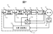
- FIG. 7 is a block diagram of a speed feedback control system including a delay compensator in a second embodiment.
- feedback is abbreviated as "FB”.
- feedback controller is abbreviated as” FB controller ".
- feed forward is abbreviated as “FF”.
- feed forward controller is abbreviated as “FF controller”.
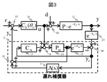
- an FB control system including the delay compensator 2 and the FB controller 16 with respect to the control object 12 including a delay. Shall be configured.
- CA and A (s) are optional FB controllers 3 and filters 1 that function effectively for the control target.
- CA and A (s) are optional FB controllers 3 and filters 1 that function effectively for the control target.
- the compensation performance equivalent to the delay compensator 62 shown in FIG. 6 having the filter 61 for example, the above-mentioned equations (1) and (2) designed in Patent Document 1 It is suitably configured.
- the delay compensator 2 includes an FB controller 3, a filter 1, and a model of a control target.
- the model to be controlled consists of a nominal plant model 14 and a nominal delay element model 15, which simulates the dynamic characteristics of the control object 12 to be actually controlled and the FB delay element 13. It is. That is, the model of the control target includes a nominal plant model that simulates the dynamics of the control target, and a nominal delay model that simulates a delay element included in the closed loop of the feedback control system.
- the model of the control target may include a nominal model of the delay elements.
- control target 12 and the FB delay element 13 may be simply referred to as a control target.
- the delay compensator 2 has as inputs the manipulated variable output by the FB controller 16 and the output of the controlled object with respect to the manipulated variable output by the FB controller 16, and outputs an FB signal with respect to the target value r.
- the delay compensator 2 is an operation in which the FB controller 16 outputs a response of a model to be controlled to a signal obtained by adding the output of an arbitrary FB controller 3 and the manipulated variable output by the FB controller 16 by the adder / subtractor 4
- a model error signal is calculated by subtracting at the adder / subtractor 39 from the response output of the control object with respect to the quantity.
- the delay compensator 2 calculates a response of the plant nominal model 14 to a signal obtained by adding the output of an arbitrary FB controller 3 and the manipulated variable output by the FB controller 16 by the adder / subtractor 4 as a predicted FB signal,
- the signal obtained by processing the model error signal by the filter 1 and the predicted FB signal are added by the adder / subtractor 35 and output as an FB signal with respect to the target value r.
- the FB controller 16 receives a deviation signal obtained by subtracting the FB signal output from the delay compensator 2 from the target value r by the adder / subtractor 37, and generates an operation amount for the control target.
- the adder / subtractor 18 is located at the input end of the control target, and the disturbance d is added to the input end of the control target.
- the delay compensator 62 designed by Patent Document 1 for example, employing the filter N of Equations (1) and (2), the step disturbance applied to the control target input end is suppressed without steady deviation. be able to.
- the delay compensator 2 shown in FIG. 3 in the present embodiment has a compensation performance equivalent to that of the delay compensator 62 which is, for example, the filter N of the equations (1) and (2). It is designed.
- CA and A (s) of the delay compensator 2 are designed, for example, as in the following formulas (4) and (5).
- Ca indicates an optional feedback controller that functions effectively for the control object, used in the design of the filter 61 of the delay compensator 62 shown in FIG.
- the delay compensators designed as equations (4) and (5) correspond to the delay compensator 42 of FIG. 4, and the input / output characteristics of the delay compensator 42 are expressed by equation (1) from simple calculation
- the input / output characteristics are equivalent to the delay compensator 62 shown in FIG. 6 including the filter N. This is explained below.
- the input / output characteristics of the delay compensator 42 of FIG. 3 can be written as Expression (9) by arranging the following equations (7) and (8) derived from FIG. 3 with respect to the input and output.
- Formula (9) becomes equal to Formula (6) by setting Formula (4), (5). Therefore, with respect to the delay compensator 2 of FIG. 3, the delay compensator 42 designed as the equations (4) and (5) has the delay compensation of FIG. 6 including the filter N shown in the equation (1). It can be seen that the device 62 is equivalent to the input / output characteristic.
- CA and A (s) of the delay compensator 2 are designed, for example, as in the following formulas (10) and (11).
- the delay compensator 2 designed as the equations (10) and (11) includes the filter N shown in the equation (2) by the equation expansion similar to the equations (6) to (9). It can be confirmed that the input / output characteristics are equivalent to the delay compensator 62 of FIG.
- Equations (4) to (5) and Equations (10) to (11) the transfer characteristic Pm of the nominal plant model 14 and the nominal delay element model 15 included in Equations (1) and (2) It can be seen that the transfer function is a simple transfer function that does not include the transfer characteristic exp ( ⁇ m ⁇ s).
- FIGS. 1 and 2 show a control system whose response is equivalent to that of FIGS. 4 and 3, respectively.
- a model FB control system 8 is configured as shown in FIG. 1 using the nominal plant model 14, the nominal delay element model 15, and the FB controller CA3.
- y corresponds to a command
- u can be regarded as an FF manipulated variable in the response rs ⁇ ym. Therefore, the model FB control system 8 is configured to follow the response y of the reference model type real FB control system 7 having a transfer characteristic of rs ⁇ y, and is configured as a model following type two degree of freedom control.
- the FB controller Cb plays the role of an FF controller by setting the model response ym to an ideal response that matches the actual response y to a high response, and the FB controller CA performs the model response ym and the actual response y. Play a role in compensating for deviations from The FB controller CA can be designed so as to stably and robustly suppress the deviation y-ym independently of the FB controller Cb from the viewpoint of two-degree-of-freedom control.
- the controller configuration of FIG. 1 can realize the model response ym-the actual response y ⁇ 0 with high response, stability and robustness.
- the Smith method compensates for the delay by canceling the actual response y including the delay with the model response ym and driving the FB controller Cb based on the predicted FB signal yi not including the delay.
- the control target has a pole at the origin, or when the control target is unstable, it is difficult to offset the actual response y by the model response ym. It is considered difficult to apply when there is a pole in the case or when the controlled object is unstable.
- the adder-subtractor 5 and the adder-subtractor 6 form ym-y
- the FB controller Cb performs the FB control based on the command value r-predicted FB signal yi.
- the idea of is the same as the Smith method.
- the controller configuration of this embodiment can realize the model response ym-the actual response y ⁇ 0 in a high response, stably and robustly. Therefore, the controller configuration of the present embodiment can be regarded as having improved the cancellation of the actual response y due to the model response ym, which is the drawback of the Smith method, by adopting the configuration of the model following type of two degree of freedom control.
- FIG. 2 which is a control system equivalent to FIG. 3, an arbitrary filter A (s) processes the FB signal of the reference model type real FB control system 27, and an arbitrary filter A (s) processes a model response.
- the processing results are sent to the adder / subtractor 6. That is, the model response ym-the actual response y is processed by an arbitrary filter A (s), and the cancellation characteristic of canceling the actual response y by the model response ym can be adjusted by an arbitrary filter A (s) is there.
- a (s) ⁇ 1 the model response ym and the actual response y need to be separately filtered with A (s) in the configuration of FIG. 2, which is not advantageous in terms of calculation cost. In this case, the configuration shown in FIG.
- FIG. 1 or FIG. 3 is configured as shown in FIG. 1 or FIG. 3 because it constitutes a configuration of model following type of two degree of freedom control and can realize model response ym-actual response y ⁇ 0 with high response and stability and robustness. For example, it is possible to improve the cancellation of the actual response y due to the model response ym, which is a drawback of the Smith method, and to compensate the delay with high response and stability even when the controlled object has a pole at the origin. It is.
- FB control system In the FB control system shown in FIG. 6, it is assumed that the filter 61 adopts the one represented by the equation (1).
- An equivalent FB control system is an FB control system including the delay compensator 42 shown in FIG. 4 as described above.
- the FB controller Cb is a PI controller, and the FB controller Cb can adjust the control response at the response frequency ⁇ b as shown in the following equation (12).
- N is any positive real number.
- any FB control Ca included in the equation (1) has the same structure as the FB controller Cb. That is, it is assumed that the FB controller Ca can adjust the controllability independently of ⁇ b at the response frequency ⁇ a, under the assumption of the equation (3).
- the second term on the right side is different, and the second term on the right side of the equation (18) has a lower order of the transfer function. Therefore, it can be understood that the calculation cost for calculating the output signal yb is lower in the delay compensator 42 of this embodiment than in the conventional delay compensator 62.
- the Pade approximation is a first-order, but in the case of a higher-order Pade approximation, the order of the transfer function of the second term on the right side of the equation (17) is increased. It can be seen that the reduction of computational cost is more effective.
- the filter N is a filter N other than the formulas (1) and (2) designed in Patent Document 1, it is shown in FIG. 3 when the filter N is designed as one that can be expressed as the following formula (19).
- the configuration of the delay compensator 2 can realize a compensation characteristic equivalent to that of the delay compensator 62 shown in FIG. 6, and can reduce the operation cost more than the delay compensator 62 shown in FIG.
- the delay compensator 52 shown in FIG. 5 is obtained. Although proof is omitted, even in this configuration, it is possible to suppress the step disturbance applied to the input end of the control target without steady-state deviation when the control target has a pole at the origin.
- the delay compensator 2 shown in FIG. 3 can exhibit compensation performance equivalent to that of the delay compensator 62 employing various filters N designed in the prior art. It can be seen that the configuration has a configuration that can reduce the operation cost compared to the delay compensator 62 of the prior art.
- the delay compensator 2 shown in FIG. 3 when the delay compensator 2 shown in FIG. 3 is mounted on hardware such as a digital arithmetic device, the operation cost of the hardware applied to the filter 61 of the delay compensator 62 does not deteriorate compared to the prior art without deterioration in control performance. Is a control method suitable for implementation that can reduce
- control method it is possible to provide a control device by hardware that is less expensive and has low arithmetic performance.
- a delay compensator described in Patent Document 1 is described as a delay compensator having equivalent compensation performance to the delay compensator 2 shown in the present embodiment.
- the FB control system may be implemented as shown in FIG. 6 using a filter 61 designed by technology.
- the processing of the filter 61 of the delay compensator 62 designed in Patent Document 1 is included in the denominator of the filter 61, exp (- ⁇ m ⁇ s), and the numerator of the filter 61. Since the calculation of the nominal plant model Pm included in the denominator can be realized by a simple control block configuration common to the calculation processing of the nominal delay element model 15 and the nominal plant model 14 required in the Smith method, According to the present invention, it is possible to provide a feedback control method suitable for implementation that can reduce the operation cost in hardware implementation while maintaining the features and advantages of the delay compensator 62 designed in Patent Document 1, and a motor control apparatus including the same. .
- the motor control method and the motor control device assume the speed control system 71 in the cascade FB control system of the AC servomotor shown in FIG. 7, and the model of the control object is specifically the following equation (21) It shall be shown to (22) and (23).
- Psm is a nominal plant model in the speed control system
- Mi is a model idealizing the current control system which is a minor loop control system in the speed control system
- ⁇ sm is included in the closed loop of the current control system and the speed control system It is the sum of all delays.
- J, Ka and Pp are inertia, motor constant and pole-log, respectively
- ⁇ i is a response frequency of the current control system.
- Equations (21) to (23) indicate that it is necessary to handle the problem that the controlled object has a pole at the origin in the design of the speed control system in the cascaded FB control system of the AC servomotor.
- the velocity FB controller 72 of the velocity control system is a PI controller, and is given by the following equations (24), (25) and (26).
- L and ⁇ s are the break point ratio and the response frequency of the speed control system, respectively.
- ⁇ i is set to about several to ten times ⁇ s.
- the current control system can not be approximated to 1 unless ⁇ i is simultaneously increased, and it must be regarded as a delay element.
- the current control system is a first-order delay element as shown in equation (23), and it is necessary to regard this as a delay element.
- the current control system is regarded as a delay element.
- a delay compensator 82 shown in FIG. 8 is configured, and as a design example of the filter 81, the following equation (27) is cited.
- velocity FB controller 86 While having the same structure as the velocity FB controller 86, its control design parameters are determined independently of the velocity FB controller 86.
- the denominator of equation (27) includes the response Mi of the current control system in addition to exp (- ⁇ m ⁇ s), and the order of the transfer function of the filter of equation (27) tends to be high. is there. Therefore, when the equation (27) is processed by the digital arithmetic unit 713, a high operation cost is required.
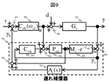
- the delay compensator 92 in the present embodiment has the rotational speed of the AC servomotor to be controlled with respect to the manipulated variable u output from the velocity FB controller 86 and the manipulated variable u output from the velocity FB controller 86. It has a sensor detection value y as an input, and outputs a speed FB signal yb with respect to the target rotational speed r.
- the delay compensator 92 rotates the model of the object to be controlled with respect to a signal obtained by the adder / subtractor 94 adding the output of an arbitrary velocity FB controller 93 to the AC servomotor to be controlled and the manipulated variable output by the velocity FB controller 86.
- the model error signal ye is calculated by subtracting the speed response from the sensor detection value y of the rotational speed of the AC servomotor which is the control object with respect to the operation amount output by the FB controller 86 by the adder / subtractor 89.
- the delay compensator 92 calculates the response of the plant nominal model 84 to the signal obtained by adding the output of an arbitrary velocity FB controller 93 and the manipulated variable output from the velocity FB controller 86 by the adder-subtractor 94 as a predicted FB signal. Then, the signal obtained by processing the model error signal by the filter 91 and the predicted FB signal are added by the adder-subtractor 95, and the result is output as the speed FB signal yb with respect to the target rotational speed r.
- the speed FB controller 86 receives a deviation signal obtained by subtracting the speed FB signal yb output from the delay compensator 92 from the target rotational speed r by the adder / subtractor 87, and generates the manipulated variable u for the control target.
- CsA and As (s) are designed, for example, as in the following formulas (29) and (30).
- the delay compensator 92 designed in this way has an input / output characteristic equivalent to that of the delay compensator 82 including the filter N shown by the equations (27) and (28) designed in Patent Document 1 from the simple calculation. It can be confirmed that That is, the delay compensator 92 designed as in equations (29) and (30) is equivalent to the delay compensator 82 including the filter of equations (27) and (28) designed in Patent Document 1 It has performance.
- Equations (29) and (30) both include the transfer characteristic Pm of the nominal plant model 84 that the equation (27) included, and the transfer characteristic Mi ⁇ exp ( ⁇ m ⁇ s) of the nominal delay element model 85. It turns out that the transfer function is simple.
- the delay compensator 92 in the speed control system of the AC servomotor shown in FIG. 9 is equivalent to the delay compensator 82 adopting various filters N designed in the prior art.
- the compensation performance can be shown, and the calculation cost can be reduced as compared with the delay compensator 82 of the prior art.
- the delay compensator 92 shown in FIG. 9 when the delay compensator 92 shown in FIG. 9 is mounted on the digital arithmetic unit 713, the calculation cost of the digital arithmetic unit 713 applied to the filter 81 of the delay compensator 82 is reduced without deterioration of control performance compared It is a control method suitable for implementation that can be reduced.
- control method it is possible to provide a control device by the digital arithmetic device 713 which is cheaper and has low operation performance.
- the filter 81 of the delay compensator 82 is expressed by the following equation (31), using the prior art:
- the delay compensator 82 shown in FIG. 9 and the delay compensator 82 including the filter of the equation (31) have equivalent compensation characteristics.
- the delay compensator 92 adopting the equation (28) can be said to be a control method suitable for mounting, if it is the equation (33), without particularly increasing the calculation cost.
- control method it is possible to provide a control device by the digital arithmetic device 713 which is cheaper and has low operation performance.
Landscapes
- Engineering & Computer Science (AREA)
- Health & Medical Sciences (AREA)
- Artificial Intelligence (AREA)
- Computer Vision & Pattern Recognition (AREA)
- Evolutionary Computation (AREA)
- Medical Informatics (AREA)
- Software Systems (AREA)
- Physics & Mathematics (AREA)
- General Physics & Mathematics (AREA)
- Automation & Control Theory (AREA)
- Feedback Control In General (AREA)
- Control Of Electric Motors In General (AREA)
Abstract
La présente invention vise à procurer un procédé de commande à rétroaction mettant en œuvre un compensateur de retard approprié pour une mise en œuvre et un dispositif de commande de moteur utilisant ledit procédé de commande à rétroaction de telle sorte que les coûts de calcul peuvent être réduits pour le compensateur de retard, qui est apte à réduire des perturbations de pas ajoutées à l'extrémité d'entrée d'une installation sans laisser d'erreurs même si l'installation a un pôle à l'origine. A cet effet, l'invention porte sur un compensateur de retard (1), lequel compensateur comprend un dispositif de commande à rétroaction (1), un filtre (1) et un modèle d'une installation, lequel reçoit la sortie d'un dispositif de commande à rétroaction (2) et une réponse de l'installation à titre d'entrée, et lequel délivre en sortie un signal de rétroaction pour le dispositif de commande (2), lequel compensateur de retard (1) produit à titre de quantité de manipulation (1) un signal obtenu par l'addition de la sortie du dispositif de commande (1) et de la sortie du dispositif de commande (2), lequel soustrait une sortie du modèle de l'installation en réponse à la quantité de manipulation (1) à partir de la réponse de l'installation de façon à obtenir un signal d'erreur (1) destiné à être utilisé à titre d'entrée pour le dispositif de commande (1), et lequel ajoute un signal résultant du passage du signal d'erreur (1) à travers le filtre à la réponse du modèle d'installation nominal à la quantité de manipulation afin de produire le signal de sortie.
Applications Claiming Priority (2)
| Application Number | Priority Date | Filing Date | Title |
|---|---|---|---|
| JP2017-209104 | 2017-10-30 | ||
| JP2017209104A JP6979330B2 (ja) | 2017-10-30 | 2017-10-30 | フィードバック制御方法、及びモータ制御装置 |
Publications (1)
| Publication Number | Publication Date |
|---|---|
| WO2019087554A1 true WO2019087554A1 (fr) | 2019-05-09 |
Family
ID=66331679
Family Applications (1)
| Application Number | Title | Priority Date | Filing Date |
|---|---|---|---|
| PCT/JP2018/032336 Ceased WO2019087554A1 (fr) | 2017-10-30 | 2018-08-31 | Procédé de commande à rétroaction et dispositif de commande de moteur |
Country Status (2)
| Country | Link |
|---|---|
| JP (1) | JP6979330B2 (fr) |
| WO (1) | WO2019087554A1 (fr) |
Families Citing this family (2)
| Publication number | Priority date | Publication date | Assignee | Title |
|---|---|---|---|---|
| JP7061684B2 (ja) * | 2018-10-09 | 2022-04-28 | 株式会社日立産機システム | フィードバック制御方法、およびフィードバック制御装置 |
| CN110231772B (zh) * | 2019-07-22 | 2022-07-15 | 广东电网有限责任公司 | 一种获取过程模型的方法、装置及设备 |
Citations (3)
| Publication number | Priority date | Publication date | Assignee | Title |
|---|---|---|---|---|
| JP2002229605A (ja) * | 2001-02-02 | 2002-08-16 | Yaskawa Electric Corp | フィードバック制御装置 |
| JP2004023910A (ja) * | 2002-06-18 | 2004-01-22 | Kobe Steel Ltd | モータ制御装置 |
| JP2018156557A (ja) * | 2017-03-21 | 2018-10-04 | 株式会社日立産機システム | 遅れ補償器のフィルタの設計方法、及びそれを用いたフィードバック制御方法、モータ制御装置 |
-
2017
- 2017-10-30 JP JP2017209104A patent/JP6979330B2/ja active Active
-
2018
- 2018-08-31 WO PCT/JP2018/032336 patent/WO2019087554A1/fr not_active Ceased
Patent Citations (3)
| Publication number | Priority date | Publication date | Assignee | Title |
|---|---|---|---|---|
| JP2002229605A (ja) * | 2001-02-02 | 2002-08-16 | Yaskawa Electric Corp | フィードバック制御装置 |
| JP2004023910A (ja) * | 2002-06-18 | 2004-01-22 | Kobe Steel Ltd | モータ制御装置 |
| JP2018156557A (ja) * | 2017-03-21 | 2018-10-04 | 株式会社日立産機システム | 遅れ補償器のフィルタの設計方法、及びそれを用いたフィードバック制御方法、モータ制御装置 |
Non-Patent Citations (1)
| Title |
|---|
| WATANABE, KEIJI ET AL.: "Disturbance Rejection of Smith Predictor Control System", TRANSACTIONS OF THE SOCIETY OF INSTRUMENT AND CONTROL ENGINEERS ., vol. 19, no. 3, 30 March 1983 (1983-03-30), pages 187 - 192, XP055614371 * |
Also Published As
| Publication number | Publication date |
|---|---|
| JP2019082791A (ja) | 2019-05-30 |
| JP6979330B2 (ja) | 2021-12-15 |
Similar Documents
| Publication | Publication Date | Title |
|---|---|---|
| JP5120654B2 (ja) | サーボ制御装置 | |
| CN110572093B (zh) | 基于电机位置伺服系统期望轨迹和干扰补偿的arc控制方法 | |
| JP7039176B2 (ja) | 遅れ補償器のフィルタの設計方法、及びそれを用いたフィードバック制御方法、モータ制御装置 | |
| CN110209122B (zh) | 一种多轴运动平台的控制方法、装置、介质及设备 | |
| CN115047760B (zh) | 一种直流电机伺服系统的ftairtsm控制方法 | |
| JP4226420B2 (ja) | 位置制御装置 | |
| CN105549385B (zh) | 多变量时滞非最小相位非方系统的解耦内模控制器、控制系统和控制方法 | |
| CN112334845B (zh) | 反馈控制方法和反馈控制装置 | |
| JP4648448B2 (ja) | Pid調節器を含む閉ループ系のプロセス制御装置 | |
| WO2019087554A1 (fr) | Procédé de commande à rétroaction et dispositif de commande de moteur | |
| CN114665780A (zh) | 永磁同步电机的控制方法、装置、设备及存储介质 | |
| CN116520680B (zh) | 一种抗扰pid控制器整定方法 | |
| Schwarzmann et al. | A flatness-based approach to internal model control | |
| JP2014075101A (ja) | 制御装置 | |
| JP2011078192A (ja) | 電動機の制御装置 | |
| CN116736728B (zh) | 一种基于geso的rdob、二自由度rimc及用于直流电机控制的rimc | |
| JPH05265515A (ja) | インターナルモデルコントローラ | |
| JP2005182427A (ja) | 制御演算装置 | |
| JP2008079478A (ja) | サーボ制御装置とその速度追従制御方法 | |
| JP2809849B2 (ja) | 2自由度調節装置 | |
| JPH07311601A (ja) | 2自由度pid調節装置 | |
| JPH04111106A (ja) | サーボ制御装置 | |
| JPH10222207A (ja) | フィードフォワード制御装置 | |
| JPH05313704A (ja) | 適応制御装置 | |
| Qiu et al. | Prescribed-Time Trajectory Tracking Controller for Flexible-Joint Manipulators: A High-Order Fully Actuated System Approach |
Legal Events
| Date | Code | Title | Description |
|---|---|---|---|
| 121 | Ep: the epo has been informed by wipo that ep was designated in this application |
Ref document number: 18872391 Country of ref document: EP Kind code of ref document: A1 |
|
| NENP | Non-entry into the national phase |
Ref country code: DE |
|
| 122 | Ep: pct application non-entry in european phase |
Ref document number: 18872391 Country of ref document: EP Kind code of ref document: A1 |