WO2019087582A1 - 自動車ドアパネル部品の補剛構造および補剛方法 - Google Patents
自動車ドアパネル部品の補剛構造および補剛方法 Download PDFInfo
- Publication number
- WO2019087582A1 WO2019087582A1 PCT/JP2018/033969 JP2018033969W WO2019087582A1 WO 2019087582 A1 WO2019087582 A1 WO 2019087582A1 JP 2018033969 W JP2018033969 W JP 2018033969W WO 2019087582 A1 WO2019087582 A1 WO 2019087582A1
- Authority
- WO
- WIPO (PCT)
- Prior art keywords
- stiffening member
- door panel
- model
- door
- stiffening
- Prior art date
- Legal status (The legal status is an assumption and is not a legal conclusion. Google has not performed a legal analysis and makes no representation as to the accuracy of the status listed.)
- Ceased
Links
Images







Classifications
-
- B—PERFORMING OPERATIONS; TRANSPORTING
- B60—VEHICLES IN GENERAL
- B60J—WINDOWS, WINDSCREENS, NON-FIXED ROOFS, DOORS, OR SIMILAR DEVICES FOR VEHICLES; REMOVABLE EXTERNAL PROTECTIVE COVERINGS SPECIALLY ADAPTED FOR VEHICLES
- B60J5/00—Doors
- B60J5/04—Doors arranged at the vehicle sides
- B60J5/042—Reinforcement elements
- B60J5/0422—Elongated type elements, e.g. beams, cables, belts or wires
- B60J5/0438—Elongated type elements, e.g. beams, cables, belts or wires characterised by the type of elongated elements
- B60J5/0441—Elongated type elements, e.g. beams, cables, belts or wires characterised by the type of elongated elements the elements having a grid-like structure, i.e. interconnected or interwoven elements
-
- B—PERFORMING OPERATIONS; TRANSPORTING
- B60—VEHICLES IN GENERAL
- B60J—WINDOWS, WINDSCREENS, NON-FIXED ROOFS, DOORS, OR SIMILAR DEVICES FOR VEHICLES; REMOVABLE EXTERNAL PROTECTIVE COVERINGS SPECIALLY ADAPTED FOR VEHICLES
- B60J5/00—Doors
- B60J5/04—Doors arranged at the vehicle sides
- B60J5/042—Reinforcement elements
- B60J5/045—Panel type elements
-
- B—PERFORMING OPERATIONS; TRANSPORTING
- B60—VEHICLES IN GENERAL
- B60J—WINDOWS, WINDSCREENS, NON-FIXED ROOFS, DOORS, OR SIMILAR DEVICES FOR VEHICLES; REMOVABLE EXTERNAL PROTECTIVE COVERINGS SPECIALLY ADAPTED FOR VEHICLES
- B60J5/00—Doors
- B60J5/04—Doors arranged at the vehicle sides
- B60J5/042—Reinforcement elements
- B60J5/0422—Elongated type elements, e.g. beams, cables, belts or wires
- B60J5/0438—Elongated type elements, e.g. beams, cables, belts or wires characterised by the type of elongated elements
- B60J5/0443—Beams
-
- B—PERFORMING OPERATIONS; TRANSPORTING
- B32—LAYERED PRODUCTS
- B32B—LAYERED PRODUCTS, i.e. PRODUCTS BUILT-UP OF STRATA OF FLAT OR NON-FLAT, e.g. CELLULAR OR HONEYCOMB, FORM
- B32B15/00—Layered products comprising a layer of metal
- B32B15/04—Layered products comprising a layer of metal comprising metal as the main or only constituent of a layer, which is next to another layer of the same or of a different material
- B32B15/08—Layered products comprising a layer of metal comprising metal as the main or only constituent of a layer, which is next to another layer of the same or of a different material of synthetic resin
-
- B—PERFORMING OPERATIONS; TRANSPORTING
- B60—VEHICLES IN GENERAL
- B60J—WINDOWS, WINDSCREENS, NON-FIXED ROOFS, DOORS, OR SIMILAR DEVICES FOR VEHICLES; REMOVABLE EXTERNAL PROTECTIVE COVERINGS SPECIALLY ADAPTED FOR VEHICLES
- B60J5/00—Doors
- B60J5/04—Doors arranged at the vehicle sides
- B60J5/0412—Lower door structure
- B60J5/0413—Inner panel, e.g. characterised by carrying components
-
- B—PERFORMING OPERATIONS; TRANSPORTING
- B60—VEHICLES IN GENERAL
- B60J—WINDOWS, WINDSCREENS, NON-FIXED ROOFS, DOORS, OR SIMILAR DEVICES FOR VEHICLES; REMOVABLE EXTERNAL PROTECTIVE COVERINGS SPECIALLY ADAPTED FOR VEHICLES
- B60J5/00—Doors
- B60J5/04—Doors arranged at the vehicle sides
- B60J5/042—Reinforcement elements
-
- B—PERFORMING OPERATIONS; TRANSPORTING
- B32—LAYERED PRODUCTS
- B32B—LAYERED PRODUCTS, i.e. PRODUCTS BUILT-UP OF STRATA OF FLAT OR NON-FLAT, e.g. CELLULAR OR HONEYCOMB, FORM
- B32B2307/00—Properties of the layers or laminate
- B32B2307/50—Properties of the layers or laminate having particular mechanical properties
- B32B2307/51—Elastic
-
- B—PERFORMING OPERATIONS; TRANSPORTING
- B60—VEHICLES IN GENERAL
- B60J—WINDOWS, WINDSCREENS, NON-FIXED ROOFS, DOORS, OR SIMILAR DEVICES FOR VEHICLES; REMOVABLE EXTERNAL PROTECTIVE COVERINGS SPECIALLY ADAPTED FOR VEHICLES
- B60J5/00—Doors
- B60J5/04—Doors arranged at the vehicle sides
- B60J5/0412—Lower door structure
- B60J5/0415—Outer panel
-
- B—PERFORMING OPERATIONS; TRANSPORTING
- B60—VEHICLES IN GENERAL
- B60J—WINDOWS, WINDSCREENS, NON-FIXED ROOFS, DOORS, OR SIMILAR DEVICES FOR VEHICLES; REMOVABLE EXTERNAL PROTECTIVE COVERINGS SPECIALLY ADAPTED FOR VEHICLES
- B60J5/00—Doors
- B60J5/04—Doors arranged at the vehicle sides
- B60J5/042—Reinforcement elements
- B60J5/0455—Reinforcement elements integrated in door structure or other door elements, e.g. beam-like shapes stamped in inner door panel
-
- B—PERFORMING OPERATIONS; TRANSPORTING
- B60—VEHICLES IN GENERAL
- B60J—WINDOWS, WINDSCREENS, NON-FIXED ROOFS, DOORS, OR SIMILAR DEVICES FOR VEHICLES; REMOVABLE EXTERNAL PROTECTIVE COVERINGS SPECIALLY ADAPTED FOR VEHICLES
- B60J5/00—Doors
- B60J5/04—Doors arranged at the vehicle sides
- B60J5/048—Doors arranged at the vehicle sides characterised by the material
Definitions
- the present invention relates to a stiffening structure and stiffening method of automotive door panel parts for improving the tensil rigidity of automotive door sheet (door panel) parts. .
- Patent Document 1 discloses that a fiber-reinforced plastic (FRP) plate is used as a photosensitive adhesive on the inner side of a metal plate such as a door or a fender in order to improve the tension rigidity of an automobile outer plate part.
- FRP fiber-reinforced plastic
- Patent Document 2 discloses a technology for bonding CFRP (Carbon Fiber-Reinforced Plastics) onto a surface of a metal plate such as a door or a roof.
- Patent Document 1 Since the technology disclosed in Patent Document 1 targets parts disposed on the side of a car such as a door or a fender, the object has a dent resistance in which the corner of the object is dented on the side of the car. For such concentrated loads, it is effective to bond the FRP by making the place where the load is concentrated as a necessity.
- distributed load such as a wide area such as tension rigidity in which the entire palm is pressed against the outer plate such as waxing is reversed. It is essential to bond FRP to the place where load is applied. For this reason, it is necessary to bond the FRP over the entire inner surface of the metal plate, and it is necessary to bond the FRP which costs several times to several tens of times over the metal plate over the wide area. There was a problem that was inevitable.
- Patent Document 2 needs to attach importance to the appearance of a car, so CFRP must be adhered to the entire surface of the front side part that is visible to the eye, which is extremely expensive. Then, although the method of making a CFRP layer extremely thin for cost reduction is also considered, when applied to this invention, the subject that the improvement in the tension
- the present invention has been made in view of the above problems, and an object thereof is a stiffening structure of an automobile door panel part capable of reducing the weight of the door panel part while improving the tension rigidity of the door panel part of the automobile It is to provide a stiffening method.
- a stiffening structure of a car door panel part is a metal plate door panel part which is curved along a height direction and in which a character line is formed, and an inner surface side of the door panel part. And an impact beam disposed on the inner surface of the door panel part, and the tension rigidity of the door panel part is improved by attaching a resin-made stiffening member to the inner surface of the door panel part, Has a plurality of vertical bone portions extending along the curve of the door panel component from the impact beam to the character line, the plurality of vertical bone portions being the door panel component It is disposed at a predetermined interval in the front-rear direction and is joined to the inner surface of the door panel component.
- a stiffening structure of a car door panel part according to a second aspect of the present invention is a door panel part which is curved along a height direction and on which a character line is formed, and an impact beam disposed on the inner surface side of the door panel part.
- a stiffening member of the door panel part is improved by sticking a resin (resin) stiffening member to the inner surface of the door panel part, and the door panel part comprises a door outer panel.
- the material of the door outer panel and the door inner panel is made of metal and metal, resin and resin, metal and resin, or a combination of resin and metal,
- a stiffening member extends in a stripe from the impact beam to the character line along the curve of the door panel component.
- a plurality of longitudinal bone part, longitudinal bone portion of said plurality of said arranged in the longitudinal direction of the door panel parts at predetermined intervals, are joined to the inner surface of the door panel parts.
- the stiffening member further includes a horizontal bone portion extending in a direction intersecting the longitudinal bone portion.
- the stiffening member is a fiber-reinforced resin having a modulus of elasticity of 10 GPa or more.
- a method of stiffening an automobile door panel component wherein the stiffening member is made of resin on the inner surface of a metal plate door panel component curved in the height direction and having an impact beam disposed on the inner surface Improve the tension rigidity by pasting, and obtain a door panel component model in which the door panel component is modeled by a two-dimensional element and / or a three-dimensional element.
- a method of stiffening an automobile door panel part according to a second aspect of the present invention is to affix a resin-made stiffening member on the inner surface of a door panel part which is curved in the height direction and on which an impact beam is disposed.
- the door panel parts are composed of a door outer panel and a door inner panel, and materials of the door outer panel and the door inner panel are metal and metal, resin and resin, metal and resin, Alternatively, a stiffening member made of any combination of resin and metal and acquiring a door panel part model obtained by modeling the door panel part with a plane element and / or a three-dimensional element and subjecting the door panel part model to optimization analysis.
- the stiffening member produced in the stiffening member producing step extends in a stripe shape from the impact beam to a character line formed on the door panel component along a curve in the height direction of the door panel component, It has a plurality of vertical bone parts arranged at predetermined intervals in the front-rear direction of the door panel part.
- the stiffening member produced in the step of producing the stiffening member further includes a transverse bone portion extending in a direction intersecting the longitudinal bone portion.
- a metal plate door panel part which is curved along the height direction and on which a character line is formed, and an impact beam disposed on the inner surface side of the door panel part are provided.
- the stiffening member of the door panel part is improved by attaching a stiffening member of a plurality of longitudinal bones extending along the curvature of the door panel part from the impact beam to the character line.
- the plurality of vertical bones are disposed at predetermined intervals in the front-rear direction of the door panel parts, and the outer surface of each vertical bone is joined to the inner surface of the door panel parts to distribute load to the door panel parts
- the amount of deformation when loaded is reduced, and the tension rigidity of the door panel component can be improved. Furthermore, according to the present invention, it is possible to achieve both the improvement of the tension rigidity and the weight reduction of the door panel component.
- FIG. 1 is a view for explaining a stiffening structure of a car door panel part according to an embodiment of the present invention.
- FIG. 2 is a view showing a flow of processing of topology optimization analysis for finding an optimum shape of a stiffening member in the stiffening structure and stiffening method of a vehicle door panel part according to the present embodiment.
- FIG. 3 is a view for explaining a design space set by topology optimization analysis and a generated stiffening member model in the stiffening structure and stiffening method of a vehicle door panel part according to the present embodiment.
- FIG. 1 is a view for explaining a stiffening structure of a car door panel part according to an embodiment of the present invention.
- FIG. 2 is a view showing a flow of processing of topology optimization analysis for finding an optimum shape of a stiffening member in the stiffening structure and stiffening method of a vehicle door panel part according to the present embodiment.
- FIG. 3 is a view for explaining a design space set by topology optimization analysis and
- FIG. 4 is a view showing an example of a load and constraint condition in topology optimization analysis of a stiffening member in a stiffening structure and a stiffening method of a vehicle door panel part according to the present embodiment.
- FIG. 5 is a diagram showing an analysis result showing an example of a stiffening member model of an optimal shape obtained by topology optimization analysis in the stiffening structure and stiffening method of a vehicle door panel part according to the present embodiment.
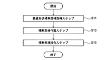
- FIG. 6 is a diagram showing a process flow of a method of stiffening automobile door panel parts according to the present embodiment.
- FIG. 7 is a diagram for explaining the evaluation method and evaluation points of tension rigidity in the first embodiment.
- FIG. 8 is a view for explaining a tension stiffness evaluation model according to Comparative Example 1 to be compared in Example 1.
- FIG. 9 is a view for explaining a tension stiffness evaluation model according to Comparative Example 2 to be compared in Example 1.
- FIG. 10 is a view showing load and restraint conditions in topology optimization analysis of a stiffening member in the second embodiment.
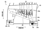
- FIG. 11 is a diagram showing a stiffening member model of an optimal shape obtained by topology optimization analysis in the second embodiment.
- FIG. 12 is a diagram for explaining an evaluation method and evaluation points of tension rigidity in the second embodiment.
- FIG. 13 is a view showing another aspect of the stiffening member in the stiffening structure of the automobile door panel part according to the present embodiment (part 1).
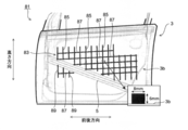
- FIG. 14 is a view showing another aspect of the stiffening member in the stiffening structure of the automobile door panel part according to the present embodiment (part 2).
- FIG. 15 is a view showing a stiffening member model of an optimal shape obtained by topology optimization analysis in Example 3 (a door outer panel made of an aluminum plate, a plate thickness of 0.8 mm).
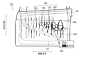
- FIG. 16 is a view showing a stiffening member model of an optimal shape obtained by topology optimization analysis in Example 3 (a door outer panel made of an aluminum plate, a plate thickness of 0.6 mm).
- a stiffening structure 1 of a car door panel part is a door which is curved along the height direction and on which a character line 3a extending in the front-rear direction is formed.
- a resin-made stiffening member having an outer panel 3 and an impact beam 5 disposed on the inner surface side of the door outer panel 3 and having a plurality of longitudinal bone portions 9 and a transverse bone portion 11 intersecting the longitudinal bone portions 9 7 is stuck to the inner surface of the door outer panel 3.
- FIGS. 3 to 5 The same applies to FIGS. 7 to 9).
- the resin-made stiffening member 7 is also arrange
- the longitudinal bone portion 9 extends in a streak shape from the impact beam 5 to the character line 3 a along the curvature of the door outer panel 3 in the height direction.
- the plurality of vertical bones 9 are arranged at predetermined intervals in the front-rear direction of the door outer panel 3, and the outer surfaces of the vertical bones 9 are joined to the inner surface of the door outer panel 3.
- the transverse bone portion 11 is provided to extend in the direction intersecting the longitudinal bone portion 9, and is provided near the central portion in the height direction of the panel surface portion 3b.
- the stiffening structure 1 according to the present embodiment is obtained based on the result of topology optimization analysis (see, for example, JP 2013-25533 A).
- the topology optimization analysis was performed by executing steps S1 to S9 shown in FIG.
- steps S1 to S9 can be executed, for example, on a computer.
- Door panel component model acquisition step S1 is a step of acquiring a door outer panel model 23 (FIG. 3) obtained by modeling the door outer panel 3 which is the door panel component using a plane element and / or a three-dimensional element.
- the door outer panel model 23 is formed with a character line 23a that is curved along the height direction and extends in the front-rear direction, and uses the impact beam 5 as a plane element and / or a solid element on the inner surface side.
- An impact beam model 25 modeled is arranged.
- the inner surface of the door outer panel model 23 refers to the surface on the indoor side of the vehicle body when the door outer panel 3 is attached to the vehicle body.
- the curvature along the height direction of the door outer panel model 23 is not limited to a shape curved at a constant curvature (curvature), and as shown in FIG. 3B, a plurality of curvatures and planes are combined.
- the inner surface may have a curved shape or a convex curved shape that is concave on the inner surface side.
- the stiffening member model generation step S3 is a step of generating a stiffening member model 27 (FIG. 3) which is made of a three-dimensional element and coupled to the inner surface of the door outer panel model 23.
- the stiffening member model 27 can be generated by generating a design space 29 on the inner surface of the door outer panel model 23 and dividing the design space 29 into three-dimensional elements.
- the stiffening member model 27 generated in the stiffening member model generation step S3 is a target of topology optimization analysis in the optimization analysis model generation step S7 described later.
- the three-dimensional element located at the site unnecessary for the stiffening is eliminated, and the three-dimensional element located at the site necessary for the stiffening remains.
- the design space 29 shown in FIG. 3 is generated along the inner surface shape of the door outer panel model 23 so as to fill the gap between the door outer panel model 23 and the impact beam model 25.
- the material property setting step S5 is a step of setting the material property of the stiffening member model 27 generated in the stiffening member model generation step S3.
- the object is to stiffen the metal plate door outer panel 3 by the resin stiffening member 7 and as material properties to be set to the stiffening member model 27 in the material property setting step S5.
- Table 1 shows values of elastic modulus, Poisson's ratio, and density set as material properties in the present embodiment.
- the material properties shown in Table 1 are set to the stiffening member model 27 as an example when the resin used for the stiffening member 7 is an isotropic material.
- the stiffening member 7 is, for example, FRP (Fiber Reinforced Plastics) having material properties of in-plane anisotropy
- the in-plane difference of the material properties of the stiffening member model 27 is Setting the in-plane anisotropy of the material property of the stiffening member model 27 by giving an angle of principal axis giving the anisotropy and setting the value of the material property corresponding to the main axis angle Can.
- stiffening member 7 is made of resin in which a plurality of layers are laminated
- a stiffening member model 27 in which a plurality of layers are laminated is generated, and the principal axis angle is set for each of the plurality of layers. Is also possible.
- the optimization analysis model generation step S7 combines the stiffening member model 27 generated in the stiffening member model generation step S3 with the door outer panel model 23 to generate the optimization analysis model 21 (see FIG. 3).
- connection between the door outer panel model 23 and the stiffening member model 27 is, for example, when the door outer panel model 23 is modeled by a plane element, a node of the solid element of the stiffening member model 27 and the door This can be done by sharing the node of the planar element of the outer panel model 23.
- the impact beam model 25 and the stiffening member model 27 may be coupled by a rigid body element.
- optimization analysis step S9 analysis conditions are given to the optimization analysis model 21 generated in the optimization analysis model generation step S7, and topology optimization analysis is performed with the stiffening member model 27 as an object of analysis processing of optimization, This is a step of determining the optimum shape of the stiffening member model 27.
- the load / restraint condition shown in FIG. 4 is given, the objective function is the volume minimum, the constraint is displacement at the load point of 1.5 mm or less (stiffness value 80 N / mm or more) And
- the load / restraint conditions are individually set at 45 mm intervals at each load point arranged in a grid at intervals of 50 mm in the height direction and the front-back direction of the door outer panel model 23, respectively.
- a distributed load of 120 N is applied individually to the normal direction of the panel surface portion 23b, and the outer surface side of the door outer panel model 23 is given at the position of the solid triangles, and the door outer panel model 23 at the positions of the dashed triangles.
- the penalty coefficient of the element is set to 2 or more to perform discretization. It is preferable to However, in the optimization analysis step S9, the analysis process of optimization can be applied not only by performing optimization analysis by topology optimization analysis but also by other optimization analysis methods. Moreover, as what performs analysis processing of optimization, analysis software using a commercially available finite element (finite element) can be used, for example.
- FIG. 5 shows the optimum shape stiffening member model 31 obtained as the optimum shape of the stiffening member model 27 by performing topology optimization analysis by the above-mentioned steps S1 to S9.
- the optimal shape stiffening member model 31 has become a fish bone having a longitudinal bone 33 extending in the height direction and a transverse bone 35 extending in the direction intersecting the longitudinal bone 33. .
- the longitudinal bone 33 extends in a stripe shape in the height direction such that one end is located in the impact beam model 25 and the other end is located in the character line 23a, and the plurality of longitudinal bones 33 extend in the front-rear direction It is arranged at a predetermined interval. And the predetermined space
- the lateral bone portion 35 extends in the front-rear direction so as to intersect the longitudinal bone portion 33 near the central portion in the height direction of the door outer panel model 23. Furthermore, a resin (a portion surrounded by a dotted circle in FIG. 5) remaining in the form of a mastic sealer was also observed at the portion where the impact beam model 25 is disposed.
- the optimal shape stiffening member model 31 has such a shape because, in the process of topology optimization analysis, the three-dimensional element does not remain in the portion where the displacement is small and supports the portion where the displacement is large It is considered that the three-dimensional element remained in
- the range not supported by the impact beam model 25 is It is thought that the result is that the lateral bone portion 35 remains so as to support the range because it is wide and the tension rigidity is low.
- the optimum shape stiffening member model 31 shown in FIG. 5 is an analysis result in the case where the arrangement of the load points for inputting the load in the topology optimization analysis is grid-like (see FIG. 4), the arrangement of the load Also in the case of the optimum shape stiffening member model obtained when the same topology optimization analysis is performed by changing (for example, arranging in a close-packed manner as illustrated in FIG. 10), the impact beam is also obtained. A plurality of vertical bones extending in the height direction from the model to the character line in the height direction and arranged at predetermined intervals in the front-rear direction were seen.
- the arrangement and shape of the longitudinal bones 9 and the lateral bones 11 in the stiffening structure 1 according to the present embodiment are based on the shape of the optimum shape stiffening member model 31 obtained by performing the topology optimization analysis described above. It can be decided.
- the predetermined interval can be set in accordance with the arrangement of the load points in the evaluation of tension rigidity set at the time of door panel design.
- the load input to each loading point can be efficiently transferred to the impact beam 5 or the character line 3a through the vertical bones 9. It can be transmitted.
- the longitudinal bone portion 33 having a width of 6.5 mm and a thickness of 10 mm can be seen in the optimum shape stiffening member model 31. Can be set to 6.5 mm and 10 mm, respectively.
- the longitudinal bone 33 is near the central portion in the height direction of the optimum shape stiffening member model 31. Since the transverse bone portions 35 extending in the intersecting direction remain, it suffices to provide the transverse bone portions 11 extending in the direction intersecting the longitudinal bone portions 9 at the central portion in the height direction of the door outer panel 3 .
- the width and thickness of the lateral bone portion 35 in the optimum shape stiffening member model 31 are 6.5 mm and 10 mm, respectively.
- the width and thickness of the lateral bone portion 11 can also be set to 6.5 mm and 10 mm, respectively.
- the reason why the tension rigidity is improved by the stiffening structure 1 according to the present embodiment is as follows.
- the stiffening member 7 is defined based on the optimum shape stiffening member model 31 which is an optimal shape for reducing the amount of deformation when the distributed load acts on the door outer panel 3 ( 1)
- the vertical bone 9 is attached to the inner surface of the door outer panel 3 so as to transmit the load to the impact beam 5 and the character line 3a.
- the amount of deformation at the load point is reduced, and the tension rigidity is improved.
- the above description is based on the optimum shape stiffening member model 31 obtained by setting the value of 30 GPa as the elastic modulus of the stiffening member model 27 in the topology optimization analysis, but the present invention relates to the present invention.
- the elastic modulus of the stiffening member 7 may be 10 GPa or more. If the elastic modulus is less than 10 GPa, the width and thickness of the stiffening member 7 increase and the weight of the member increases, so it is difficult to reduce the weight.
- the fact that weight reduction can be achieved by setting the elastic modulus of the stiffening member 7 to 10 GPa or more will be specifically described in Example 2 described later.
- the stiffening member 7 may be provided with a longitudinal bone 13 which intersects the transverse bone 11 separately from the longitudinal bone 9 (FIG. 1).
- the shape of the longitudinal bone portion 13 can be determined based on the shape of the longitudinal bone portion 37 in the optimum shape stiffening member model 31.
- the lateral bone portion 35 does not always remain, and depending on the arrangement of the impact beam model 25, an optimal shape stiffening in which a portion corresponding to the lateral bone portion 35 intersecting the longitudinal bone portion 33 does not remain.
- a member model could be obtained.
- the stiffening structure according to the present invention may have only a plurality of longitudinal bone portions 9 arranged at predetermined intervals in the front-rear direction.
- the lateral bones may remain at a plurality of locations intersecting the longitudinal bones, and the stiffening structure according to the present invention may have lateral bones at a plurality of locations in the center of the door panel.
- the arrangement and shape of the longitudinal bones 9 and the transverse bones 11 are determined based on the optimal shape stiffening member model 31 obtained by performing topology optimization analysis, but the present invention
- the arrangement and shape of the longitudinal bone portion 9 and the transverse bone portion 11 may be appropriately set as follows.
- the spacing of the load points and the spacing of the longitudinal bones 33 correspond to each other in the topology optimization analysis described above.
- the interval can be appropriately set according to the arrangement of the load points in the evaluation of tension rigidity set at the time of door panel design.
- the widths of the longitudinal bone portion 33 and the transverse bone portion 35 are both approximately 6.5 mm.
- the widths of the longitudinal bone 33 and the transverse bone 35 were both about 15 mm. From this, the widths of the vertical bone portion 9 and the horizontal bone portion 11 can be appropriately set in accordance with the elastic modulus of the resin used for the stiffening member 7.
- the thickness of the longitudinal bone part 9 and the transverse bone part 11 was set to 10 mm in said topology optimization analysis, it is not limited to this value, The tension rigidity and weight of the stiffening structure 1 It can set up suitably, considering both of.
- the central portion is provided so as to extend in a direction intersecting the longitudinal bone portion 9.
- the arrangement of the impact beam 5 makes it desirable to arrange the lateral bone portion 11 in a range where the tension rigidity is low because the inner surface side of the door outer panel 3 is not supported by the impact beam 5.
- the distributed load input to the portion can be dispersed.
- the amount of deformation when the distributed load acts on the panel surface portion 3b of the door outer panel 3 can be reduced, and the tension rigidity can be appropriately improved.
- the impact beam 5 is disposed below the central portion in the height direction, and the character line 3a is formed at the upper portion in the height direction.
- the vertical bone portion 9 has a shape extending from the impact beam 5 to the upper side in the height direction up to the character line 3a.
- the impact beam is disposed at the upper side in the height direction and the character line is lower in the height direction. Even in the case where they are formed, it is sufficient to provide a plurality of vertical bones extending in a line from the impact beam to the character line along the curvature of the door outer panel.
- the stiffening structure according to the present invention may further be provided with a longitudinal bone portion 13 extending in a stripe shape in a height direction crossing the transverse bone portion 11.
- the longitudinal bone portion 13 may not have its end located at the impact beam 5 or the character line 3a.
- vertical bones 9 may be provided which extend from the impact beam 5 to the character line 3a.
- the present invention couples a resin stiffening member to a door panel component consisting of a door outer panel and a door inner panel.
- the combination of the material of the door outer panel and the material of the door inner panel may be any of metal and metal, resin and resin, metal and resin, or resin and metal.
- a stiffening structure 71 in which a substantially straight longitudinal bone portion 75 and a transverse bone portion 77 are combined with a stiffening member 73 forming a honeycomb shape; It may be a stiffening structure 81 in which a stiffening member 83 in which a longitudinal bone portion 85 and a transverse bone portion 87 form a lattice shape is joined as shown in FIG.
- a stiffening member 83 in which a longitudinal bone portion 85 and a transverse bone portion 87 form a lattice shape is joined as shown in FIG.
- a plurality of longitudinal bones extending in a line form from the impact beam 5 to the character line 3a and a transverse bone crossing the longitudinal bones are regularly arranged.
- the simple shape is preferred in terms of the manufacture of the stiffening member.
- the vertical bone portion 9 extends upward in the height direction toward the character line 3a above the impact beam 5.
- the stiffening structure of the automobile door panel component according to the present invention is, for example, height direction from the impact beam 5 as shown in FIGS.
- the longitudinal bone portion 79 or the longitudinal bone portion 89 extending in a linear manner may be provided below.
- the method of stiffening an automobile door panel component according to the present embodiment is tensioned by attaching a stiffening member to the inner surface of a metal plate door panel component curved in the height direction and having an impact beam disposed on the inner surface side.
- the rigidity is to be improved, and as shown in FIG. 6, it comprises an optimum shape stiffening member acquiring step S11, a stiffening member manufacturing step S13, and a stiffening member joining step S15.
- the optimum shape stiffening member acquisition step S11 acquires a door outer panel model 23 obtained by modeling the door outer panel 3 with a plane element and / or a three-dimensional element, and uses the door outer panel model 23 as a target of optimization analysis. And an optimization analysis for determining the optimum shape of the stiffening member model 27.
- the optimization analysis can apply the above-described topology optimization analysis method, and by performing steps S1 to S9 shown in FIG. 2, an optimal shape stiffening member which is the optimal shape of the stiffening member model 27.
- a model 31 (see FIG. 5) is determined.
- the stiffening member production step S13 is a step of producing the stiffening member 7 to be joined to the inner surface of the door outer panel 3 based on the optimum shape stiffening member model 31 obtained in the optimum shape stiffening member acquisition step S11.
- the stiffening members 7 extend in a stripe shape from the impact beam 5 to the character line 3 a along the curvature of the door outer panel 3 in the height direction, and a plurality of longitudinal members arranged at predetermined intervals in the front-rear direction of the door outer panel 3 It has a bone portion 9.
- the distance between the longitudinal bones 33 in the front-rear direction is about 50 mm, and the width and thickness are about 6.5 mm and 10 mm, respectively.
- the thickness can be set as the arrangement and shape of the longitudinal bone portion 9 of the stiffening member 7.
- the lateral bones 35 having a width and a thickness of about 6.5 mm and 10 mm respectively extend in the vicinity of the central portion in the height direction
- a transverse bone portion 11 extending in a direction intersecting with the longitudinal bone portion 9 is provided near the central portion in the height direction, and the width and thickness thereof can be set to 6.5 mm and 10 mm, respectively.
- the optimum shape stiffening member model 31 is an example of the analysis result obtained under the load and restraint conditions shown in FIG. 4 with the door outer panel model 23 shown in FIG. 3)
- the optimal shape supplement obtained by performing topology optimization analysis under these conditions The arrangement, shape, thickness, and width of the longitudinal bones 9 and the lateral bones 11 of the stiffening member 7 may be set based on the rigid member model 31. The thickness and the width may not be constant among the stiffening members.
- the stiffening member 7 has the lateral bone portion 11. However, depending on the arrangement of the impact beam 5 on the inner surface side of the target door outer panel 3, for example, it corresponds to the lateral bone portion 35. In some cases, it is possible to obtain an optimum shape stiffening member model 31 in which no portion remains. In such a case, only the vertical bone portion 9 may be joined to the inner surface of the door outer panel 3 as the stiffening member 7.
- stiffening member model 31 although it does not extend from the impact beam model 25 to the character line 23a, it is disposed at substantially the same intervals as the longitudinal bones 33, and intersects the transverse bones 35 and has a height.
- the stiffening member 7 produced in the stiffening member producing step S13 the longitudinal bone portions 13 intersecting with the transverse bone portions 11 separately from the longitudinal bone portions 9 are You may provide.
- a longitudinal bone portion 9 extending from the impact beam 5 to the character line 3a may be further provided so as to intersect the transverse bone portion 11.
- the shape of the stiffening member 7 may be determined from the balance.
- the stiffening member 7 produced in the stiffening member producing step S13 is not limited to the one produced so as to have the same shape as the optimum shape stiffening member model 31, and a plurality of longitudinal bone portions 9 and And as long as it has the cross bone part 11 as needed. Furthermore, if the load input to the panel surface 3b is transmitted to the impact beam 5 and the character line 3a through the vertical bone 9, the vertical bone 9 extends intermittently in the height direction. It may be.
- end portion on the impact beam 5 side of the vertical bone portion 9 may replace the conventionally used mastic sealer by filling the gap between the inner surface of the door outer panel 3 and the impact beam 5. It is preferable in terms of weight reduction.
- the stiffening member joining step S15 is a step of joining the outer surface of the stiffening member 7 manufactured in the stiffening member manufacturing step S13 to the inner surface of the door outer panel 3.
- an adhesive agent can be used to attach to the inner surface of the door outer panel 3.
- the amount of deformation when the distributed load is applied to the door panel parts can be reduced, and the tension rigidity of the door panel parts can be improved. Furthermore, when the shape of the stiffening member is determined based on the result of optimization analysis by reducing the thickness of the metal plate of the door panel component, the tension rigidity is improved while the thickness of the door panel component is reduced. , Can reduce the weight of the entire door panel parts.
- the effects of the improvement of the tension rigidity and the weight reduction according to the present invention will be specifically described in Examples 1 and 2 described later.
- the rigid method may be directed to a door panel component consisting of a door outer panel and a door inner panel.
- the combination of the materials of the door outer panel and the door inner panel can be any of metal and metal, resin and resin, metal and resin, or resin and metal.
- the door outer panel 3 is attached to the inner surface of a door outer panel model 23 made of metal plate (steel plate) with reduced plate thickness.
- Topology optimization analysis for finding the optimum shape of the stiffening member model 27 and the tension rigidity of the tension stiffness evaluation model 41 in which the optimum shape stiffening member model 31 obtained by the topology optimization analysis is connected to the door outer panel model 23 The weight change was determined.
- the optimal shape of the stiffening member model 27 is the optimal shape stiffening member model 31 obtained by the topology optimization analysis method (see FIG. 2) described in the above-described embodiment.
- the analysis conditions of the optimization analysis for obtaining the optimum shape stiffening member model 31 are the same as the embodiment described above, under the load / restraint conditions shown in FIG. The conditions were set to a displacement of 1.5 mm or less at the load point.
- the stiffening member model 27 was an isotropic material, and the values shown in Table 1 were set as the material properties.
- FIG. 7 shows the positions of the evaluation point A, evaluation point B and evaluation point C for evaluating the tension rigidity of the door outer panel model 23, and the restraint position ( ⁇ in the figure) in tension rigidity evaluation.
- the tension stiffness value was calculated by the following equation using the load input by the indenter at each evaluation point (evaluation point A to evaluation point C) shown in FIG. 7 and the displacement at each evaluation point.
- Tension rigidity value (N / mm) load (N) / displacement at each evaluation point (mm)
- the reference value of the tension rigidity value is 80 N / mm, and the tension rigidity value above this reference value is good.
- bonding of the optimal shape stiffening member model 31 was calculated.
- the thickness of the door outer panel model 23 is gauged down from 0.6 mm to 0.5 mm, whereby the weight of the door outer panel model 23 is reduced by 603 g. Therefore, the weight change due to the connection of the optimal shape stiffening member model 31 is a value obtained by adding the weight of the optimal shape stiffening member model 31 to the reduction amount ( ⁇ 603 g) due to the gauge down.
- a tension rigidity evaluation model 43 in which a substantially rectangular stiffening member model 45 is joined to the inner surface of the door outer panel model 23 is shown in FIG.
- a tension rigidity evaluation model 47 in which a stiffening member model 49 having only a part of a longitudinal bone extending in the height direction from the center in the front-rear direction in the impact beam model 25 is combined is For each of the tension stiffness evaluation model 43 and the tension stiffness evaluation model 47, tension stiffness and a change in weight were determined in the same manner as in Inventive Example 1.
- Table 2 shows a door outer panel model in which the thickness is kept at 0.6 mm without combining the invention example 1, the comparative example 1 and the comparative example 2 whose gauge thickness is reduced to 0.5 mm and the stiffening member model as a conventional example.
- Fig. 10 shows the results of tension stiffness values and weight changes obtained for 23.
- a stiffening member model 45 having a shape that covers the entire inner surface of the door outer panel model 23 is combined, and the tension rigidity value satisfies the reference value at any of the evaluation points.
- the weight of the stiffening member model 45 is 3618 g
- the weight change at this time is +3015 g
- the use of the stiffening member model 45 results in a significant increase in weight.
- Comparative Example 2 is a combination of a stiffening member model 49 having a shape extending in the height direction at the central portion of the door outer panel model 23, and the weight change of the stiffening member model 49 is 50 g.
- the weight is reduced to -553 g, compared to the conventional example.
- the tension rigidity value although the reinforcement member model 49 is affixed to the inner surface side of the evaluation point A, although the tension rigidity value satisfies the reference value beyond the conventional example, the evaluation point B and the evaluation point The result was that the tension stiffness value at C was lower than the tension stiffness value of the conventional example and was significantly out of the reference value.
- Invention Example 1 is one in which the optimum shape stiffening member model 31 whose optimum shape is obtained by topology optimization is connected to the door outer panel model 23 whose plate thickness is reduced to 0.5 mm, and the tension rigidity values are all evaluated. It was a good result exceeding the standard value in point. Further, the weight of the optimum shape stiffening member model 31 is 136 g, and the weight change at this time is -467 g, which is lighter than the conventional example.
- an optimum shape stiffening member model is obtained in the case where the arrangement of load points for evaluating the tension rigidity of the door outer panel is different from that of the first embodiment described above, and the obtained optimum shape stiffening member model is obtained as a door.
- the tension stiffness and weight change of the tension stiffness evaluation model connected to the outer panel model were obtained.
- the tension stiffness of the tension stiffness evaluation model when the modulus of elasticity was changed was evaluated, and the preferable range of the modulus of elasticity of the resin used for the stiffening member was examined.
- Example 2 the load optimization condition shown in FIG. 10 is given as a case where the arrangement of the load points for evaluating the tension rigidity is different, and the topology optimization analysis described in the above embodiment (see FIG. 2) Did.
- load / restraint conditions as shown in FIG. 10, load points arranged in a grid (dotted line in FIG. 10) and load points (solid line in FIG. 10) arranged at the center of the grid of the grid are set.
- a distributed load of 120 N is individually given in the normal direction of the panel surface 23b of the door outer panel model 23 by a region of 45 mm, and the outer surface side of the door outer panel model 23 is The inner surface side of the door outer panel model 23 was restrained at the position of the broken triangle ⁇ .
- the material properties of the stiffening member model 27 were set to the values shown in Table 1 described above. Furthermore, as the optimization analysis conditions, as in the first embodiment, the objective function is the volume minimum, and the constraint is a displacement of 1.5 mm or less at the load point. Then, structural analysis is performed when a load is input to one of the individual load points arranged as shown in FIG. 10, each structural analysis is individually performed on all the load points, and each load point is analyzed. After the structural analysis in which the load was input was integrated, volume minimization of the stiffening member model 27 (FIG. 3) was performed. Here, the weighting at the time of integrating the structural analysis of each load point was equal.
- FIG. 11 shows an optimum shape stiffening member model 51 obtained by topology optimization analysis given the load and constraint conditions shown in FIG.
- the optimal shape stiffening member model 51 extends in the direction intersecting the longitudinal bone portion 53 extending in a streak shape in the height direction and the longitudinal bone portion 53, similarly to the optimal shape stiffening member model 31 shown in FIG. It became bone-like in fish having existing lateral bones 55.
- the longitudinal bone portion 53 has one end located in the impact beam model 25 and the other end located in the character line 23 a, and a plurality of longitudinal bone portions 53 are disposed in the front-rear direction of the door outer panel model 23. Furthermore, the width of the vertical bone portion 53 is 4.5 mm ((a) in FIG. 11) on the front side of the door outer panel model 23 and 14.5 mm ((b) in FIG. 11) on the rear side. Unlike in the case of the optimum shape stiffening member model 31, the width of the vertical bone portion 53 is different depending on the position in the front-rear direction.
- the optimum shape stiffening member model 51 shown in FIG. 11 further includes a longitudinal bone portion 57 extending in a height direction in the vicinity of the height direction central portion on the rear side of the door outer panel model 23. .
- the impact beam model 25 is obliquely disposed with the rear end 25a of the impact beam model 25 positioned below the central portion in the height direction, so the range not supported by the impact beam model 25 is wide. It is considered that the tensile rigidity is lowered, and the vertical bone portion 57 remains in the topology optimization analysis so as to support the range.
- the tension rigidity of the tension stiffness evaluation model 61 is obtained by adding the evaluation point D to the same evaluation points A to C as in Example 1 at each evaluation point shown in FIG. 12 and inputting the input load and the input load It evaluated by the tension rigidity value calculated using the displacement in a point.
- the reference value of the tension rigidity value is set to 80 N / mm, and the tension rigidity value equal to or higher than the reference value is regarded as good.
- the weight reduction was also evaluated by the weight change when the optimum shape stiffening member model 51 was connected to the door outer panel model 23 whose gauge thickness was reduced from 0.6 mm to 0.5 mm as in the first embodiment.
- Table 3 shows the results of the tension rigidity value and the weight change of the tension rigidity evaluation model 61.
- the conventional example is the result of the door outer panel model 23 in which the plate thickness is kept at 0.6 mm without connecting the stiffening member model, as in the first embodiment described above.
- the invention example 2 is the result of the tension rigidity evaluation model 61 in which the optimum shape stiffening member model 51 obtained by giving the material characteristics shown in Table 1 to the stiffening member model 27 is combined.
- Comparative Example 3 is a combination of the optimum shape stiffening member model 51 having the same shape as that of the invention example 2, so that a weight change of -500 g was obtained as compared with the conventional example.
- Table 3 shows the result that the tension rigidity value increases as the elastic modulus of the optimum shape stiffening member model 51 is increased. This suggests that by increasing the elastic modulus of the resin used for the stiffening member, the weight of the stiffening member can be reduced within the range where the tension rigidity value satisfies the reference value, and the weight of the door panel component can be further reduced. Then, when the elastic modulus of the resin used for the stiffening member is increased to further reduce the weight, according to the results shown in Table 3, the elastic modulus is 10 GPa or more so that the tension rigidity value at each evaluation point satisfies the reference value. It is understood that it is preferable to use a resin.
- a fiber reinforced resin is a resin having an elastic modulus of 10 GPa or more.
- the optimum shape stiffening member model 51 is determined by the topology optimization analysis set to the elastic modulus 30 GPa of the stiffening member model, and the determined optimum shape This is the result of evaluating the tension rigidity by changing only the elastic modulus of the stiffening member model 51. From this result, the elastic modulus to be set in the stiffening member model in the topology optimization analysis for obtaining the optimum shape stiffening member model It is suggested that it should be 10 GPa or more.
- the stiffening member model of the shape most suitable for stiffening the door panel part is the door panel part. It has been shown that it is desirable to form a fish bone having a longitudinal bone portion extending in the height direction and further having a transverse bone portion extending in a direction crossing the longitudinal bone portion, and it is made of resin of optimum shape. It has been shown that by connecting the stiffening members and reducing the thickness of the door panel parts, it is possible to achieve both the improvement of the tension rigidity and the weight reduction. Furthermore, it was shown that setting the elastic modulus of the optimally shaped stiffening member to 10 GPa or more is preferable for improving the tension rigidity of the door panel part.
- an optimum shape stiffening member model in the case of using aluminum as the material is determined.
- the tension stiffness and weight change of tension stiffness evaluation model in which the optimum shape stiffening member model obtained was connected to the door outer panel model were obtained. Furthermore, the tension rigidity of the tension stiffness evaluation model was evaluated when the elastic modulus of the obtained optimum shape stiffening member model was changed, and the preferable range of the elastic modulus of the resin used for the stiffening member was examined.
- Example 3 the elastic modulus and the density of the aluminum used as the material of the door outer panel model 23 were 70 GPa and 2.7 g / cm 3 , respectively. Further, with the plate thickness of the door outer panel model 23 set to 0.8 mm or 0.6 mm, topology optimization analysis was performed for each plate thickness (thickness) in the same manner as in Example 2 to obtain an optimum shape stiffening member model.
- Example 1 For the material characteristics other than the elastic modulus of the stiffening member model 27 in the topology optimization analysis, the values shown in Table 1 were set. Furthermore, the load constraint conditions were the same as in Example 2 (see FIG. 10), and the optimization analysis conditions were the same as in Example 1, but the objective function was the volume minimum and the constraint was a displacement of 1.5 mm or less at the load point. .
- FIG. 15 shows an optimum shape stiffening member model 93 obtained by optimization analysis when the plate thickness of the aluminum outer door panel model 23 is 0.8 mm. Even when the material of the door outer panel model 23 is aluminum, the optimum shape stiffening member model 93 is the same as the optimum shape stiffening member model 31 (FIG. 5) obtained as the material of the door outer panel model 23 as steel.
- the bone structure has a longitudinal bone portion 95 extending in the height direction from the impact beam model 25 and a transverse bone portion 97 extending in the direction intersecting the longitudinal bone portion 95.
- FIG. 16 shows an optimum shape stiffening member model 103 obtained by optimization analysis when the plate thickness of the door outer panel model 23 made of aluminum plate is 0.6 mm. Similar to the optimal shape stiffening member model 93 in the door outer panel model 23 with a thickness of 0.8 mm, the optimal shape stiffening member model 103 includes a longitudinal bone portion 105 extending in the height direction from the impact beam model 25 and As a result, a bone structure having a transverse bone portion 107 extending in a direction crossing the longitudinal bone portion 105 is obtained.
- a tensile rigidity evaluation model 91 (FIG. 15) in which the optimum shape stiffening member model 93 is joined to the door outer panel model 23 made of aluminum plate having a thickness of 0.8 mm and aluminum plate having a thickness of 0.6 mm
- the tension rigidity and weight reduction were evaluated for each of the tension stiffness evaluation models 101 (FIG. 16) in which the optimum shape stiffening member model 103 was connected to the door outer panel model 23 of FIG.
- the tension rigidity of the tension stiffness evaluation models 91 and 101 was input as the displacement at each evaluation point when the load is input to each evaluation point (evaluation point A to evaluation point D) shown in FIG. 12 as in the second embodiment. It evaluated by the tension rigidity value calculated using load.
- the reference value of the tension rigidity is set to 80 N / mm, and the tension rigidity value equal to or higher than the reference value is regarded as good.
- the invention example 10 is a result of the tension rigidity evaluation model 101 in which the optimum shape stiffening member model 103 shown in FIG. 16 is connected to the door outer panel model 23 having a thickness of 0.6 mm. Furthermore, Inventive Example 11, Inventive Example 12 and Inventive Example 13 are the results of changing the elastic modulus of the optimum shape stiffening member model 103 to the values shown in Table 4, respectively.
- the door outer panel model and the door are evaluated in order to evaluate the tension rigidity of the door panel component when the combination of the material of the door outer panel and the door inner panel is different for the door panel component including the door outer panel and the door inner panel.
- the tension stiffness and weight change of the tension stiffness evaluation model in which the optimum shape stiffening member model was combined with the door panel component model consisting of the inner panel model were obtained.
- the optimal shape stiffening member model coupled to the door panel component model is the optimal shape stiffening member model 51 (FIG. 11) obtained for the door outer panel model 23 made of steel, or the material is aluminum
- the optimum shape stiffening member model 93 (FIG. 15) obtained for the door outer panel model 23 was used.
- Table 5 shows combinations of the material, thickness and optimum shape stiffening member model of the door outer panel model and the door inner panel model in the tension rigidity evaluation model.
- the inner panel shows a door inner panel model
- the outer panel shows a door outer panel model.
- the material of the inner panel and the outer panel was aluminum (Al), steel (Fe) or a resin, and the values shown in Table 1 were set for the material properties of the resin.
- the tension stiffness value of the tension stiffness evaluation model is, similarly to the second embodiment, a displacement at each evaluation point when the load is inputted to each evaluation point (evaluation point A to evaluation point D) shown in FIG. It evaluated by the tension rigidity value calculated using. Moreover, about weight reduction, it evaluated by the weight change when the optimal shape stiffening member model 93 or 103 is couple
- the tensile rigidity value was increased as compared with the conventional example 3 and the conventional example 4, and the result that the weight of 456 g was reduced was obtained.
- the tensile rigidity value was increased as compared with Conventional Example 5 and Conventional Example 6, and the result was obtained that the weight was reduced by 325 g.
- the tensile rigidity value was increased as compared with the conventional example 7 to the conventional example 9, respectively, and the result that the weight was reduced by 174 g was obtained.
- tension rigidity and weight of a tension stiffness evaluation model in which a stiffening member model in which longitudinal and transverse bone portions are regularly arranged is connected to a door panel component model consisting of a door outer panel model and a door inner panel model. I asked for a change.
- the door outer panel model is a stiffening member model having the same shape as the honeycomb-shaped stiffening member 73 shown in FIG. 13 or a stiffening member model having the same shape as the lattice-shaped stiffening member 83 shown in FIG. And the tension stiffness evaluation models are respectively generated.
- the material of the door outer panel model and the door inner panel model in the tension rigidity evaluation model is steel, and the combination of the plate thickness of the steel plate door outer panel model and the stiffening member model is shown in Table 6.
- the material of the stiffening member model was resin, and the values shown in Table 1 were set for the material properties of the resin.
- the tension stiffness value of the tension stiffness evaluation model is, similarly to the second embodiment, a displacement at each evaluation point when the load is inputted to each evaluation point (evaluation point A to evaluation point D) shown in FIG. It evaluated by the tension rigidity value calculated using. Moreover, about weight reduction, it evaluated by the weight change when the stiffening member model 73 or 83 is couple
- Example 10 is a result when a door panel component model to which a stiffening member model is not coupled is used as a tension stiffness evaluation model.
- Invention Example 21 is a result of a tension stiffness evaluation model in which a stiffening member model having the same shape as the stiffening member 73 shown in FIG. 13 is joined to the door outer panel model, and
- Invention Example 22 is a stiffener shown in FIG. It is a result of the tension rigidity evaluation model which couple
- the tension rigidity value increased compared to 10.
- the weight was reduced to 268 g, and in the invention example 22, the weight was reduced.
- the present invention it is possible to provide a stiffening structure and a stiffening method of a car door panel part capable of reducing the weight of the car door panel part while improving the tension rigidity of the car door panel part.
Landscapes
- Engineering & Computer Science (AREA)
- Mechanical Engineering (AREA)
- Textile Engineering (AREA)
- Body Structure For Vehicles (AREA)
- Securing Of Glass Panes Or The Like (AREA)
- Laminated Bodies (AREA)
- Processing Of Solid Wastes (AREA)
Abstract
本発明に係る自動車ドアパネル部品の補剛構造は、高さ方向に沿って湾曲し、キャラクタライン3aが形成された金属板製のドアアウタパネル3と、ドアアウタパネル3の内面側に配設されたインパクトビーム5とを備え、ドアアウタパネル3の内面に樹脂製の補剛部材7を貼付することによりドアアウタパネル3の張り剛性を向上させるものであって、補剛部材7は、ドアアウタパネル3の前記湾曲に沿ってインパクトビーム5からキャラクタライン3aまで筋状に延在する複数の縦骨部9を有し、該複数の縦骨部9は、ドアアウタパネル3の前後方向において所定の間隔で配置され、各縦骨部9の外面がドアアウタパネル3の内面に接合されている。
Description
本発明は、自動車の(automotive)金属板(metal sheet)製ドアパネル(door panel)部品(part)の張り剛性(tensil rigidity)を向上させる自動車ドアパネル部品の補剛(stiffening)構造および補剛方法に関する。
自動車のドア、ルーフ(roof)、フード(hood)等の自動車外板(outer panel)部品の重要な機能の一つに張り剛性を担保することがある。自動車外板部品の張り剛性を向上させるため、例えば、特許文献1には、ドアやフェンダー(fender)等の金属板の内側にFRP(Fiber-Reinforced Plastics;繊維強化プラスチック)板を感光性接着剤(photosensitive adhesive)により接着(adhere)する技術が開示されている。また、特許文献2には、ドアやルーフのような金属板表面にCFRP(Carbon Fiber-Reinforced Plastics;炭素繊維強化プラスチック)を接着する技術が開示されている。
特許文献1に開示されている技術は、ドアやフェンダーなどの自動車の側面(side)に配置される部品を対象とするため、物の角が自動車側面にあたって局部が凹むデント性(dent resistance)のような集中荷重(concentrated load)に対しては荷重が集中する箇所を必須としてFRPを接着することで効果を奏する。しかし、ワックス掛け(waxing)のような手のひら全体を外板に押し付ける張り剛性のような広い面積が反転するような分布荷重(distributed load)について、特許文献1に開示されている技術によれば、荷重が加わる箇所にFRPを接着することを必須とする。このため、金属板の内側全面に渡ってFRPを接着することになり、広い面積全体に金属板に比べて数倍から数十倍のコストが掛かるFRPを接着する必要があるため、著しいコスト上昇が避けられないといった問題があった。
また、特許文献2に開示されている技術は、自動車の外観を重視する必要があるため、人目に触れる表側の部品の全面にCFRPを接着しなくてはならず、非常に高コストとなる。そこで、コスト低減のためCFRP層を極薄くする方法も考えられるが、本発明に適用した場合、目的とするドアパネル部品の張り剛性の向上を見込めないという課題があった。
このように、自動車パネル部品にFRPやCFRPを接着する技術は数多く開示されているものの、分布荷重が作用された時の張り剛性を向上させるとともに、軽量化(weight reduction of automotive body)を達成する技術はこれまでに提案されていなかった。
本発明は、上記課題に鑑みてなされたものであって、その目的は、自動車のドアパネル部品の張り剛性を向上させつつ、該ドアパネル部品を軽量化することができる自動車ドアパネル部品の補剛構造および補剛方法を提供することにある。
本発明の第1の態様に係る自動車ドアパネル部品の補剛構造は、高さ方向に沿って湾曲し、キャラクタライン(character line)が形成された金属板製ドアパネル部品と、該ドアパネル部品の内面側に配設されたインパクトビーム(impact beam)とを備え、前記ドアパネル部品の内面に樹脂製の補剛部材を貼付することにより前記ドアパネル部品の張り剛性を向上させるものであって、前記補剛部材は、前記ドアパネル部品の前記湾曲に沿って前記インパクトビームから前記キャラクタラインまで筋状に延在する複数の縦骨部(vertical bone portion)を有し、該複数の縦骨部は、前記ドアパネル部品の前後方向において所定の間隔で配置され、前記ドアパネル部品の内面に接合されている。
本発明の第2の態様に係る自動車ドアパネル部品の補剛構造は、高さ方向に沿って湾曲し、キャラクタラインが形成されたドアパネル部品と、該ドアパネル部品の内面側に配設されたインパクトビームとを備え、前記ドアパネル部品の内面に樹脂(resin)製の補剛部材を貼付することにより前記ドアパネル部品の張り剛性を向上させるものであって、前記ドアパネル部品は、ドアアウタパネル(door outer panel)とドアインナパネル(door inner panel)とからなり、該ドアアウタパネルとドアインナパネルの材質は、金属と金属、樹脂と樹脂、金属と樹脂、又は、樹脂と金属のいずれかの組み合せからなり、前記補剛部材は、前記ドアパネル部品の前記湾曲(curve)に沿って前記インパクトビームから前記キャラクタラインまで筋状に延在する複数の縦骨部を有し、該複数の縦骨部は、前記ドアパネル部品の前後方向において所定の間隔で配置され、前記ドアパネル部品の内面に接合されている。
本発明に係る自動車ドアパネル部品の補剛構造は、上記発明において、前記補剛部材は、前記縦骨部と交差する方向に延在する横骨部(horizontal bone portion)をさらに有する。
本発明に係る自動車ドアパネル部品の補剛構造は、上記発明において、前記補剛部材は、弾性率(modulus of elasticity)が10GPa以上の繊維強化樹脂(fiber-reinforced resin)である。
本発明の第1の態様に係る自動車ドアパネル部品の補剛方法は、高さ方向に湾曲し、内面側にインパクトビームが配設された金属板製ドアパネル部品の前記内面に樹脂製の補剛部材を貼付することにより張り剛性を向上させるものであって、前記ドアパネル部品を平面要素(two-dimensional element)及び/又は立体要素(three-dimensional element)でモデル化(modeling)したドアパネル部品モデルを取得し、該ドアパネル部品モデルに最適化解析の対象とする補剛部材モデルを結合し、該補剛部材モデルの最適な形状を求める最適化解析を行う最適形状補剛部材取得ステップと、該最適な形状の補剛部材モデルに基づいて、前記ドアパネル部品の内面に接合する(bond)補剛部材を作製する補剛部材作製ステップと、該作製した補剛部材を前記ドアパネル部品の内面に接合する補剛部材接合ステップと、を含み、前記補剛部材作製ステップで作製する補剛部材は、前記ドアパネル部品の高さ方向の湾曲に沿って前記インパクトビームから前記金属板製ドアパネル部品に形成されたキャラクタラインまで筋状に延在し、前記ドアパネル部品の前後方向において所定の間隔で配置される複数の縦骨部を有する。
本発明の第2の態様に係る自動車ドアパネル部品の補剛方法は、高さ方向に湾曲し、内面側にインパクトビームが配設されたドアパネル部品の前記内面に樹脂製の補剛部材を貼付することにより張り剛性を向上させるものであって、前記ドアパネル部品は、ドアアウタパネルとドアインナパネルとからなり、該ドアアウタパネルとドアインナパネルの材質は、金属と金属、樹脂と樹脂、金属と樹脂、又は、樹脂と金属のいずれかの組み合せからなり、前記ドアパネル部品を平面要素及び/又は立体要素でモデル化したドアパネル部品モデルを取得し、該ドアパネル部品モデルに最適化解析の対象とする補剛部材モデルを結合し、該補剛部材モデルの最適な形状を求める最適化解析を行う最適形状補剛部材取得ステップと、該最適な形状の補剛部材モデルに基づいて、前記ドアパネル部品の内面に接合する補剛部材を作製する補剛部材作製ステップと、該作製した補剛部材を前記ドアパネル部品の内面に接合する補剛部材接合ステップと、を含み、前記補剛部材作製ステップで作製する補剛部材は、前記ドアパネル部品の高さ方向の湾曲に沿って前記インパクトビームから前記ドアパネル部品に形成されたキャラクタラインまで筋状に延在し、前記ドアパネル部品の前後方向において所定の間隔で配置される複数の縦骨部を有する。
本発明に係る自動車ドアパネル部品の補剛方法は、上記発明において、前記補剛部材作製ステップで作製する補剛部材は、前記縦骨部と交差する方向に延在する横骨部をさらに有する。
本発明においては、高さ方向に沿って湾曲し、キャラクタラインが形成された金属板製ドアパネル部品と、ドアパネル部品の内面側に配設されたインパクトビームとを備え、ドアパネル部品の内面に樹脂製の補剛部材を貼付することによりドアパネル部品の張り剛性を向上させるものであって、補剛部材は、ドアパネル部品の湾曲に沿ってインパクトビームからキャラクタラインまで筋状に延在する複数の縦骨部を有し、複数の縦骨部は、ドアパネル部品の前後方向において所定の間隔で配置され、各縦骨部の外面がドアパネル部品の内面に接合されていることにより、ドアパネル部品に分布荷重を負荷したときの変形量が低減し、ドアパネル部品の張り剛性を向上させることができる。さらに、本発明によれば、張り剛性の向上とドアパネル部品の軽量化との双方を達成することができる。
<自動車ドアパネル部品の補剛構造>
本発明の実施の形態の一例に係る自動車ドアパネル部品の補剛構造1は、図1に示すように、高さ方向に沿って湾曲し、前後方向に延在するキャラクタライン3aが形成されたドアアウタパネル3と、ドアアウタパネル3の内面側に配設されたインパクトビーム5とを備え、複数の縦骨部9と、縦骨部9に交差する横骨部11とを有する樹脂製の補剛部材7がドアアウタパネル3の内面に貼付されたものである。ここで、図1は、ドアアウタパネル3を自動車の幅方向の室外側から側面視したものであり、室内側に配設されているインパクトビーム5は破線で図示した(以下、図3~図5、図7~図9においても同様)。また、樹脂製の補剛部材7も室内側に配設される。
本発明の実施の形態の一例に係る自動車ドアパネル部品の補剛構造1は、図1に示すように、高さ方向に沿って湾曲し、前後方向に延在するキャラクタライン3aが形成されたドアアウタパネル3と、ドアアウタパネル3の内面側に配設されたインパクトビーム5とを備え、複数の縦骨部9と、縦骨部9に交差する横骨部11とを有する樹脂製の補剛部材7がドアアウタパネル3の内面に貼付されたものである。ここで、図1は、ドアアウタパネル3を自動車の幅方向の室外側から側面視したものであり、室内側に配設されているインパクトビーム5は破線で図示した(以下、図3~図5、図7~図9においても同様)。また、樹脂製の補剛部材7も室内側に配設される。
縦骨部9は、ドアアウタパネル3の前記高さ方向の湾曲に沿ってインパクトビーム5からキャラクタライン3aまで筋状に延在している。複数の縦骨部9は、ドアアウタパネル3の前後方向において所定の間隔で配置され、各縦骨部9の外面がドアアウタパネル3の内面に接合されている。そして、横骨部11は、縦骨部9と交差する方向に延在するように設けられたものであり、パネル面部3bの高さ方向中央部付近に設けられている。
本実施の形態に係る補剛構造1は、トポロジー最適化解析(例えば、特開2013-25533号参照)を行い、その解析結果に基づいて得られたものである。そして、トポロジー最適化解析は、図2に示すステップS1からステップS9を実行することにより行った。そこで、図2に示す各ステップにおける処理について以下に説明する。なお、ステップS1からステップS9は、例えば、コンピュータ上で実行することができる。
≪ドアパネル部品モデル取得ステップ≫
ドアパネル部品モデル取得ステップS1は、平面要素及び/又は立体要素を用いて前記ドアパネル部品であるドアアウタパネル3をモデル化したドアアウタパネルモデル23(図3)を取得するステップである。ここで、ドアアウタパネルモデル23は、高さ方向に沿って湾曲し、前後方向に延在するキャラクタライン23aが形成されており、内面側にはインパクトビーム5を平面要素及び/又は立体要素を用いてモデル化したインパクトビームモデル25が配設されている。また、ドアアウタパネルモデル23の内面とは、ドアアウタパネル3を車体に取り付けたときに該車体の室内側となる面のことをいう。
ドアパネル部品モデル取得ステップS1は、平面要素及び/又は立体要素を用いて前記ドアパネル部品であるドアアウタパネル3をモデル化したドアアウタパネルモデル23(図3)を取得するステップである。ここで、ドアアウタパネルモデル23は、高さ方向に沿って湾曲し、前後方向に延在するキャラクタライン23aが形成されており、内面側にはインパクトビーム5を平面要素及び/又は立体要素を用いてモデル化したインパクトビームモデル25が配設されている。また、ドアアウタパネルモデル23の内面とは、ドアアウタパネル3を車体に取り付けたときに該車体の室内側となる面のことをいう。
なお、ドアアウタパネルモデル23の高さ方向に沿った湾曲は、一定の曲率(curvature)で湾曲している形状に限らず、図3(b)に示すように、複数の湾曲や平面が組み合わされた内面形状であってもよく、また、該内面形状は、内面側に凹状となる湾曲や凸状の湾曲を有するものであってもよい。
≪補剛部材モデル生成ステップ≫
補剛部材モデル生成ステップS3は、立体要素からなりドアアウタパネルモデル23の内面に結合する補剛部材モデル27(図3)を生成するステップである。
補剛部材モデル生成ステップS3は、立体要素からなりドアアウタパネルモデル23の内面に結合する補剛部材モデル27(図3)を生成するステップである。
ここで、補剛部材モデル27は、図3に示すように、ドアアウタパネルモデル23の内面に設計空間29を生成し、設計空間29を立体要素で要素分割することにより生成することができる。
そして、補剛部材モデル生成ステップS3において生成する補剛部材モデル27は、後述する最適化解析モデル生成ステップS7におけるトポロジー最適化解析の対象となるものである。トポロジー最適化解析の過程において、補剛に不要な部位に位置する立体要素は消去され、補剛に必要となる部位に位置する立体要素が残存する。
なお、図3に示す設計空間29は、ドアアウタパネルモデル23とインパクトビームモデル25との間の隙間をも埋めるようにドアアウタパネルモデル23の内面形状に沿って生成した。
≪材料特性設定ステップ≫
材料特性設定ステップS5は、補剛部材モデル生成ステップS3において生成した補剛部材モデル27の材料特性を設定するステップである。
材料特性設定ステップS5は、補剛部材モデル生成ステップS3において生成した補剛部材モデル27の材料特性を設定するステップである。
本実施の形態では、樹脂製の補剛部材7により金属板製ドアアウタパネル3を補剛することを対象とし、材料特性(material property)設定ステップS5において補剛部材モデル27に設定する材料特性としては、樹脂の弾性率、ポアソン比(Poisson’s ratio)及び密度(density)などが挙げられる。表1に、本実施の形態において材料特性として設定した弾性率、ポアソン比および密度の値を示す。

表1に示す材料特性は、補剛部材7に用いる樹脂が等方性材料(isotropic material)である場合の一例として補剛部材モデル27に設定するものである。補剛部材7が、例えば面内異方性(in-plane anisotropy)の材料特性を有するFRP(Fiber Reinforced Plastics;繊維強化樹脂)の場合には、補剛部材モデル27の材料特性の面内異方性を与える主軸角度(angle of principal axis)を与え、該主軸角度に対応する前記材料特性の値を設定することで、補剛部材モデル27の材料特性の面内異方性を設定することができる。さらに、補剛部材7を複数の層が積層してなる樹脂製とする場合においては、複数の層が積層する補剛部材モデル27を生成し、該複数の層ごとに主軸角度を設定することも可能である。
≪最適化解析モデル生成ステップ≫
最適化解析モデル生成ステップS7は、補剛部材モデル生成ステップS3において生成した補剛部材モデル27をドアアウタパネルモデル23に結合して最適化解析モデル21(図3参照)を生成するものである。
最適化解析モデル生成ステップS7は、補剛部材モデル生成ステップS3において生成した補剛部材モデル27をドアアウタパネルモデル23に結合して最適化解析モデル21(図3参照)を生成するものである。
ドアアウタパネルモデル23と補剛部材モデル27との結合は、例えば、ドアアウタパネルモデル23が平面要素でモデル化されている場合、補剛部材モデル27の立体要素のノード(節点)(node)とドアアウタパネルモデル23の平面要素のノードとを共有することにより行うことができる。
さらに、前述のとおり、本発明では、最適化解析モデル生成ステップS7においては、インパクトビームモデル25と補剛部材モデル27については剛体要素で結合するとよい。
≪最適化解析ステップ≫
最適化解析ステップS9は、最適化解析モデル生成ステップS7において生成した最適化解析モデル21に解析条件を与え、補剛部材モデル27を最適化の解析処理を行う対象としてトポロジー最適化解析を行い、補剛部材モデル27の最適な形状を求めるステップである。
最適化解析ステップS9は、最適化解析モデル生成ステップS7において生成した最適化解析モデル21に解析条件を与え、補剛部材モデル27を最適化の解析処理を行う対象としてトポロジー最適化解析を行い、補剛部材モデル27の最適な形状を求めるステップである。
最適化解析モデル21に与える解析条件としては、最適化解析モデル21に荷重を付加する位置および変位を拘束する位置を与える荷重・拘束条件と、最適化解析の目的に応じて設定する目的関数(objective function)および制約条件(constraint condition)がある。
本実施の形態におけるトポロジー最適化解析の例では、図4に示す荷重・拘束条件を与えるとともに、目的関数を体積最小、制約条件を荷重点での変位1.5mm以下(剛性値80N/mm以上)とした。
荷重・拘束条件は、図4に示すように、ドアアウタパネルモデル23の高さ方向および前後方向それぞれに50mm間隔で格子状に配置した各荷重点において、個別にφ45mmの領域によりドアアウタパネルモデル23のパネル面部23bの法線方向(normal direction)に120Nの分布荷重を個別に与え、実線の△印の位置においてはドアアウタパネルモデル23の外面側を、破線の△印の位置においてはドアアウタパネルモデル23の内面側を拘束した。
そして、前記格子状に配置した個別の荷重点のうちの一つに荷重を入力した場合の構造解析(structural analysis)を行い、当該構造解析を全ての荷重点に対して個別に行って、各荷重点に荷重を入力した構造解析を総合した後、補剛部材モデル27の体積最小化を行い、補剛部材モデル27の最適な形状である最適形状補剛部材モデル31を求めた。ここで、各荷重点についての構造解析を総合する際の重みは均等とした。
また、最適化解析ステップS9においてトポロジー最適化解析に密度法(density method)を適用する場合、要素(element)のペナルティ係数(penalty coefficient)を2以上に設定して離散化(discretization)を行うようにすることが好ましい。もっとも、最適化解析ステップS9においては、トポロジー最適化解析により最適化解析を行うものに限らず、他の最適化解析方法により最適化の解析処理を適用することができる。また、最適化の解析処理を行うものとしては、例えば、市販されている有限要素(finite element)を用いた解析ソフトを使用することができる。
図5に、上記のステップS1からステップS9によりトポロジー最適化解析を実行し、補剛部材モデル27の最適な形状として求められた最適形状補剛部材モデル31を示す。最適形状補剛部材モデル31は、高さ方向に延在する縦骨部33と、縦骨部33に交差する方向に延在する横骨部35を有する魚の骨状(fish bone)となった。
そして、縦骨部33は、一端がインパクトビームモデル25に位置し、他端がキャラクタライン23aに位置するように高さ方向に筋状に延在し、複数の縦骨部33が前後方向において所定の間隔で配置されている。そして、隣り合う縦骨部33同士の所定の間隔は、圧子(indenter)により荷重を入力する荷重点の間隔とほぼ一致している。
一方、横骨部35は、ドアアウタパネルモデル23の高さ方向の中央部付近において、縦骨部33に交差するように前後方向に延在している。さらに、インパクトビームモデル25が配置されている部位にもマスチックシーラ(mastic sealer)状に残存した樹脂(図5中、点線○印で囲んだ部位)が見られた。
最適形状補剛部材モデル31がこのような形状となったのは、トポロジー最適化解析の過程において、変位(displacement)が小さい部位には立体要素は残存せず、変位が大きい部位を支持するように立体要素が残存したためであると考えられる。
特に、インパクトビームモデル25の後端25aが高さ方向中央部よりも下方に位置してインパクトビームモデル25が斜めに配置されている該中央部においてはインパクトビームモデル25により支持されていない範囲が広くて張り剛性が低いため、当該範囲を支持するように横骨部35が残存する結果になったと考えられる。
また、図5に示す最適形状補剛部材モデル31は、トポロジー最適化解析において荷重を入力する荷重点の配置を格子状とした場合(図4参照)の解析結果であったが、荷重の配置を変更(例えば、図10に例を示す最密充填状(close-packed)に配置)して同様のトポロジー最適化解析を行った場合に得られた最適形状補剛部材モデルにおいても、インパクトビームモデルからキャラクタラインまで高さ方向に筋状に延在し、前後方向に所定の間隔で配設された複数の縦骨部が見られた。
本実施の形態に係る補剛構造1における縦骨部9および横骨部11の配置および形状は、上記のトポロジー最適化解析を行って求められた最適形状補剛部材モデル31の形状に基づいて決定することができる。
まず、縦骨部9の配置に関して、前述のとおり、最適形状補剛部材モデル31における縦骨部33の前後方向における所定の間隔が、荷重点の間隔に対応していることから、前後方向における所定の間隔は、ドアパネル設計時に設定した張り剛性の評価において荷重点の配置に合わせて設定することができる。このように、縦骨部9の間隔を圧子による荷重点の間隔と一致させることで、各荷重点に入力した荷重を縦骨部9を介してインパクトビーム5又はキャラクタライン3aへと効率的に伝達させることができる。
次に、縦骨部9の形状に関して、本実施の形態では最適形状補剛部材モデル31において幅6.5mm、厚さ10mmの縦骨部33が見られることから、縦骨部9の幅および厚さを、それぞれ6.5mmおよび10mmに設定することができる。
さらに、横骨部11の配置に関しては、図1に示すようにインパクトビーム5が斜めに配置されている場合、最適形状補剛部材モデル31の高さ方向中央部付近においては縦骨部33に交差する方向に延在する横骨部35が残存していることから、ドアアウタパネル3の高さ方向中央部において縦骨部9と交差する方向に延在する横骨部11を設ければよい。
そして、横骨部11の形状に関しては、縦骨部9と同様、本実施の形態では最適形状補剛部材モデル31における横骨部35の幅および厚さがそれぞれ6.5mmおよび10mmであることから、補剛構造1においては、横骨部11の幅および厚さについても、それぞれ6.5mmおよび10mmに設定することができる。
本実施の形態に係る補剛構造1により、張り剛性が向上する理由は以下のとおりである。補剛構造1は、ドアアウタパネル3に分布荷重が作用したときの変形量を小さくするのに最適な形状である最適形状補剛部材モデル31に基づいて補剛部材7が規定されているため(図1)、分布荷重がパネル面部3bに入力したとき、該荷重をインパクトビーム5やキャラクタライン3aへと伝達させるように縦骨部9がドアアウタパネル3の内面に貼付されている。これにより、荷重点における変形量が低下し、張り剛性が向上することになる。
なお、上記の説明は、トポロジー最適化解析において補剛部材モデル27の弾性率として30GPaの値を設定して得られた最適形状補剛部材モデル31に基づいたものであるが、本発明に係る補剛部材7の弾性率は10GPa以上とすればよい。弾性率が10GPa未満では補剛部材7の幅や厚みが増し、部材の重量が増加するため、軽量化が困難である。補剛部材7の弾性率を10GPa以上とすることで軽量化ができることに関しては、後述する実施例2において具体的に説明する。
また、最適形状補剛部材モデル31においては、インパクトビームモデル25からキャラクタライン23aまで延在していないものの、縦骨部33とほぼ等しい間隔で配置し、横骨部35に交差して高さ方向に延在する縦骨部37が見られることから、補剛部材7は、縦骨部9とは別に横骨部11と交差する縦骨部13を設けてもよい(図1)。この場合、縦骨部13の形状は、最適形状補剛部材モデル31における縦骨部37の形状に基づいて決定することができる。
さらに、トポロジー最適化解析において横骨部35は必ずしも残存するとは限らず、インパクトビームモデル25の配置によっては、縦骨部33に交差する横骨部35に相当する部位が残存しない最適形状補剛部材モデルが得られる場合もあった。このような場合、本発明に係る補剛構造は、前後方向に所定の間隔で配置する複数の縦骨部9のみを有するものであってもよい。また、横骨部は縦骨部と交差する複数の箇所に残存する場合があり、本発明に係る補剛構造は、ドアパネル中央の複数箇所に横骨部を有するものでもよい。
なお、上記の説明は、縦骨部9および横骨部11の配置および形状をトポロジー最適化解析を行って得られた最適形状補剛部材モデル31に基づいて決定するものであるが、本発明に係る補剛構造は、縦骨部9および横骨部11の配置および形状を、以下のように適宜設定するものであってもよい。
例えば、複数の縦骨部9の前後方向における所定の間隔に関しては、前述のトポロジー最適化解析において、荷重点の間隔と縦骨部33の間隔が対応していたことから、縦骨部9の間隔は、ドアパネル設計時に設定した張り剛性の評価において荷重点の配置に応じて適宜設定することができる。
また、前述のトポロジー最適化解析において、補剛部材モデル27の弾性率を30GPaとした場合、縦骨部33および横骨部35の幅はいずれも約6.5mmであり、補剛部材モデル27の弾性率を10GPaとした場合、縦骨部33および横骨部35の幅はいずれも約15mmであった。このことから、縦骨部9および横骨部11の幅は、補剛部材7に用いる樹脂の弾性率に応じて適宜設定することができる。
また、縦骨部9および横骨部11の厚さは、上記のトポロジー最適化解析では10mmに設定していたが、この値に限定されるものではなく、補剛構造1の張り剛性および重量の双方を考慮して、適宜設定することができる。
さらに、横骨部11の配置に関しては、図1に示すように、インパクトビーム5の後端5aが高さ方向中央部よりも下方に位置してインパクトビーム5が斜めに配設されている場合、該中央部において縦骨部9に交差する方向に延在するように設けることが好ましい。
これは、前記中央部においてはインパクトビーム5により支持されていない範囲が広いため、当該範囲における張り剛性が低いことに起因するためである。このことは、インパクトビーム5の配置によって、ドアアウタパネル3の内面側がインパクトビーム5により支持されていないために張り剛性が低い範囲に、横骨部11を配置することが望ましいことを意味する。
これより、内面側がインパクトビーム5により支持されていない部位に縦骨部9と交差方向に延在する横骨部11を設けることにより、当該部位に入力した分布荷重を分散させることができる。その結果、ドアアウタパネル3のパネル面部3bに分布荷重が作用したときの変形量を小さくすることができ、張り剛性を適切に向上させることができる。
なお、上記の説明では、インパクトビーム5が高さ方向中央部よりも下方側に位置するように配置され、かつ、キャラクタライン3aが高さ方向上部に形成されているため、補剛部材7の縦骨部9は、インパクトビーム5から高さ方向上部側にキャラクタライン3aまで延在する形状であったが、例えば、インパクトビームが高さ方向上部に配設されてキャラクタラインが高さ方向下部に形成されている場合であっても、ドアアウタパネルの湾曲に沿って前記インパクトビームから前記キャラクタラインまで筋状に延在する複数の縦骨部を設ければよい。
また、本発明に係る補剛構造は、図1に示すように、横骨部11に交差して高さ方向に筋状に延在する縦骨部13をさらに設けたものであってもよく、縦骨部13は、その端部がインパクトビーム5又はキャラクタライン3aに位置するものでなくてもよい。もっとも、縦骨部13の代わりに、インパクトビーム5からキャラクタライン3aまで延在する縦骨部9を設けてもよい。
上記の説明は、ドアパネル部品として金属板製のドアアウタパネルを補剛する場合に関するものであったが、本発明は、ドアアウタパネルとドアインナパネルとからなるドアパネル部品に樹脂製の補剛部材を結合するものであってもよく、ドアアウタパネルとドアインナパネルの材質の組み合わせは、金属と金属、樹脂と樹脂、金属と樹脂、又は、樹脂と金属のいずれであってもよい。
さらに本発明は、図13に示すように略直線状の縦骨部75と横骨部77とがハニカム形状(honeycomb shape)を形成する補剛部材73を結合した補剛構造71や、図14に示すように縦骨部85と横骨部87とが格子形状を形成する補剛部材83を結合した補剛構造81であってもよい。補剛部材73や補剛部材83のように、インパクトビーム5からキャラクタライン3aまで筋状に延在する複数の縦骨部と、該縦骨部に交差する横骨部とが規則的に配置された簡単な形状とすることで、補剛部材の製作の点において好ましい。
また、上記の説明は、図1に示すように、インパクトビーム5よりも上方にあるキャラクタライン3aに向かって縦骨部9が高さ方向の上方に延在するものであったが、本発明に係る自動車ドアパネル部品の補剛構造は、インパクトビームよりも下方にキャラクタラインが形成されたドアパネル部品(図示なし)においては、例えば図13および図14に示すように、インパクトビーム5から高さ方向の下方に筋状に延在する縦骨部79または縦骨部89を設けたものであってもよい。
<自動車ドアパネル部品の補剛方法>
次に、本実施の形態に係る自動車ドアパネル部品の補剛方法について説明する。
次に、本実施の形態に係る自動車ドアパネル部品の補剛方法について説明する。
本実施の形態に係る自動車ドアパネル部品の補剛方法は、高さ方向に湾曲し、内面側にインパクトビームが配設された金属板製ドアパネル部品の前記内面に補剛部材を貼付することにより張り剛性を向上させるものであって、図6に示すように、最適形状補剛部材取得ステップS11と、補剛部材作製ステップS13と、補剛部材接合ステップS15と、を備えたものである。
以下、ドアパネル部品として図1に示すドアアウタパネル3を対象とした場合について、上記の各ステップを説明する。
≪最適形状補剛部材取得ステップ≫
最適形状補剛部材取得ステップS11は、ドアアウタパネル3を平面要素及び/又は立体要素でモデル化したドアアウタパネルモデル23を取得し、ドアアウタパネルモデル23に最適化解析の対象とする補剛部材モデル27を結合し、補剛部材モデル27の最適な形状を求める最適化解析を行うステップである。
最適形状補剛部材取得ステップS11は、ドアアウタパネル3を平面要素及び/又は立体要素でモデル化したドアアウタパネルモデル23を取得し、ドアアウタパネルモデル23に最適化解析の対象とする補剛部材モデル27を結合し、補剛部材モデル27の最適な形状を求める最適化解析を行うステップである。
最適化解析は、前述のトポロジー最適化解析方法を適用することができ、図2に示すステップS1からステップS9まで実行することにより、補剛部材モデル27の最適な形状である最適形状補剛部材モデル31(図5参照)が求められる。
≪補剛部材作製ステップ≫
補剛部材作製ステップS13は、最適形状補剛部材取得ステップS11で求めた最適形状補剛部材モデル31に基づいて、ドアアウタパネル3の内面に接合する補剛部材7を作製するステップである。補剛部材7は、ドアアウタパネル3の高さ方向の湾曲に沿ってインパクトビーム5からキャラクタライン3aまで筋状に延在し、ドアアウタパネル3の前後方向において所定の間隔で配置された複数の縦骨部9を有するものである。
補剛部材作製ステップS13は、最適形状補剛部材取得ステップS11で求めた最適形状補剛部材モデル31に基づいて、ドアアウタパネル3の内面に接合する補剛部材7を作製するステップである。補剛部材7は、ドアアウタパネル3の高さ方向の湾曲に沿ってインパクトビーム5からキャラクタライン3aまで筋状に延在し、ドアアウタパネル3の前後方向において所定の間隔で配置された複数の縦骨部9を有するものである。
図5に示す最適形状補剛部材モデル31において、縦骨部33の前後方向における間隔は約50mmであり、また、幅および厚さはそれぞれ約6.5mmおよび10mmであるので、これらの間隔、幅および厚さを補剛部材7の縦骨部9の配置および形状として設定することができる。
また、最適形状補剛部材モデル31においては、幅および厚さがそれぞれ約6.5mmおよび10mmの横骨部35が高さ方向中央部付近に延在しているので、補剛部材7においては、高さ方向中央部付近において縦骨部9と交差する方向に延在する横骨部11を設け、その幅および厚さをそれぞれ6.5mmおよび10mmに設定することができる。
なお、最適形状補剛部材モデル31は、図3に示すドアアウタパネルモデル23を解析対象とし、図4に示す荷重・拘束条件の下で求めた解析結果の一例であるため、対象とするドアアウタパネル3や、張り剛性を評価するための荷重・拘束条件および最適化解析条件など、各種条件が変更された場合には、それらの条件の下でトポロジー最適化解析を行って得られた最適形状補剛部材モデル31に基づいて補剛部材7の縦骨部9および横骨部11の配置、形状、厚み、幅を設定すればよい。なお、厚みや幅は、補剛部材の中でも一定でなくてもよい。
また、上記の説明では、補剛部材7は横骨部11を有するものであったが、例えば、対象とするドアアウタパネル3の内面側におけるインパクトビーム5の配置によっては、横骨部35に相当する部位が残存しない最適形状補剛部材モデル31が得られる場合もある。このような場合には、補剛部材7として縦骨部9のみをドアアウタパネル3の内面に接合するものであってもよい。
なお、最適形状補剛部材モデル31においては、インパクトビームモデル25からキャラクタライン23aまで延在していないものの、縦骨部33とほぼ等しい間隔で配置し、横骨部35に交差して高さ方向に延在する縦骨部37が見られることから、補剛部材作製ステップS13で作製する補剛部材7においては、縦骨部9とは別に横骨部11と交差する縦骨部13を設けてもよい。
もっとも、縦骨部13の代わりとして、インパクトビーム5からキャラクタライン3aまで延在する縦骨部9を横骨部11に交差させるようにさらに設けてもよく、目標とする張り剛性や重量との兼ね合いから補剛部材7の形状を決定すればよい。
このように、補剛部材作製ステップS13で作製する補剛部材7は、最適形状補剛部材モデル31と同一形状となるように作製したものに限られるものではなく、複数の縦骨部9と、必用に応じて横骨部11とを有するものであればよい。さらに、縦骨部9は、パネル面部3bに入力した荷重が縦骨部9を介してインパクトビーム5やキャラクタライン3aに伝達するものであれば、断続的に高さ方向に延在するものであってもよい。
また、縦骨部9のインパクトビーム5側の端部は、ドアアウタパネル3の内面とインパクトビーム5との間の隙間を埋める形状とすることにより、従来用いられていたマスチックシーラを代替することができ、軽量化の面で好ましい。
≪補剛部材接合ステップ≫
補剛部材接合ステップS15は、補剛部材作製ステップS13で作製した補剛部材7の外面をドアアウタパネル3の内面に接合するステップである。補剛部材7の接合としては、例えば、接着剤(adhesive agent)を用いてドアアウタパネル3の内面に貼付することができる。
補剛部材接合ステップS15は、補剛部材作製ステップS13で作製した補剛部材7の外面をドアアウタパネル3の内面に接合するステップである。補剛部材7の接合としては、例えば、接着剤(adhesive agent)を用いてドアアウタパネル3の内面に貼付することができる。
以上、本実施の形態に係る自動車ドアパネル部品の補剛構造および方法によれば、ドアパネル部品に分布荷重を負荷したときの変形量が低減し、前記ドアパネル部品の張り剛性を向上させることができる。さらに、ドアパネル部品の金属板の板厚を減少させて最適化解析をした結果に基づいて補剛部材の形状を決定した場合、板厚を減少させる前のドアパネル部品よりも張り剛性を向上させつつ、ドアパネル部品全体を軽量化することができる。本発明による張り剛性の向上と軽量化の効果に関しては、後述する実施例1および実施例2にて具体的に示す。
なお、上記の説明は、前述の本実施の形態に係る自動車ドアパネル部品の補剛構造と同様に、ドアパネル部品としてドアアウタパネルを対象としたものであったが、本発明に係る自動車ドアパネル部品の補剛方法は、ドアアウタパネルとドアインナパネルとからなるドアパネル部品を対象とするものであってもよい。そして、該ドアパネル部品において、ドアアウタパネルとドアインナパネルの材質の組み合わせは、金属と金属、樹脂と樹脂、金属と樹脂、又は、樹脂と金属、のいずれかとすることができる。
本発明の効果を確認する実験を行ったので、これについて説明する。本実施例1では、発明例1として、図1に示すドアアウタパネル3の張り剛性の向上と軽量化を目的とし、板厚を減少した金属板(鋼板)製ドアアウタパネルモデル23の内面に貼付する補剛部材モデル27の最適な形状を求めるトポロジー最適化解析を行い、該トポロジー最適化解析により求めた最適形状補剛部材モデル31をドアアウタパネルモデル23に結合した張り剛性評価モデル41の張り剛性と重量変化を求めた。ここで、補剛部材モデル27の最適な形状は、前述の実施の形態で述べたトポロジー最適化解析方法(図2参照)により得られた最適形状補剛部材モデル31とした。
最適形状補剛部材モデル31を求める最適化解析の解析条件は、前述の実施の形態と同様、図4に示す荷重・拘束条件を与え、最適化解析条件としては、目的関数を体積最小、制約条件を荷重点での変位1.5mm以下とした。また、補剛部材モデル27は等方性材料とし、その材料特性には前述の表1に示す値を設定した。
本実施例1において、張り剛性は以下のように評価した。図7に、ドアアウタパネルモデル23の張り剛性を評価する評価点A、評価点Bおよび評価点Cの位置と、張り剛性評価における拘束位置(図中の△)を示す。張り剛性値は、図7に示す各評価点(評価点A~評価点C)において圧子により入力した荷重と、各評価点における変位を用いて次式により算出した。
張り剛性値(N/mm)=荷重(N)/各評価点における変位(mm)
そして、トポロジー最適化解析において120Nの荷重を入力したときの変位の制約条件を1.5mm以下としたことから、張り剛性値の基準値を80N/mmとし、この基準値以上の張り剛性値を良好とした。
また、軽量化の評価に関しては、ドアアウタパネルモデル23の板厚減少と最適形状補剛部材モデル31の結合による重量変化を算出した。本実施例1では、ドアアウタパネルモデル23の板厚を0.6mmから0.5mmにゲージダウンさせるものとし、これによりドアアウタパネルモデル23の重量は603g減少する。したがって、最適形状補剛部材モデル31の結合による重量変化は、ゲージダウンによる減少量(-603g)に最適形状補剛部材モデル31の重量を加えた値とした。
なお、本実施例1では、比較対象として、図8に示すように、ドアアウタパネルモデル23の内面に略矩形の補剛部材モデル45を結合した張り剛性評価モデル43を比較例1、図9に示すように、インパクトビームモデル25における前後方向の中央部から高さ方向に延在する縦骨部の一部のみを有する補剛部材モデル49を結合した張り剛性評価モデル47を比較例2とし、張り剛性評価モデル43および張り剛性評価モデル47それぞれについて、発明例1と同様に張り剛性および重量変化を求めた。
表2に、板厚を0.5mmにゲージダウンした発明例1、比較例1および比較例2と、従来例として補剛部材モデルを結合せずに板厚を0.6mmのままとしたドアアウタパネルモデル23について得られた張り剛性値および重量変化の結果を示す。

比較例1は、ドアアウタパネルモデル23の内面側の全面にわたる形状の補剛部材モデル45を結合したものであり、張り剛性値はいずれの評価点においても基準値を満たしている。しかしながら、補剛部材モデル45の重量は3618gであり、このときの重量変化は+3015gとなり、補剛部材モデル45を用いることにより重量が大幅に増加する結果となった。
比較例2は、ドアアウタパネルモデル23の中央部において高さ方向に延在する形状の補剛部材モデル49を結合したものであり、補剛部材モデル49の重量は50gであることから重量変化は-553gとなり、従来例に比べて軽量化されている。しかしながら、張り剛性値に関しては、評価点Aはその内面側に補剛部材モデル49が貼付されているので張り剛性値は従来例を超えて基準値を満たしているものの、評価点Bおよび評価点Cにおける張り剛性値が従来例の張り剛性値を下回り大幅に基準値を外れる結果となった。
発明例1は、トポロジー最適化により最適な形状を求めた最適形状補剛部材モデル31を板厚を0.5mmに減少させたドアアウタパネルモデル23に結合したものであり、張り剛性値はすべての評価点で基準値を超える良好な結果であった。さらに、最適形状補剛部材モデル31の重量は136gであり、このときの重量変化は-467gとなり、従来例より軽量化された。
以上より、本発明に係る自動車ドアパネル部品の補剛構造および補剛方法により、最適な形状の樹脂製の補剛部材を接合するとともに前記金属板製ドアパネル部品の板厚を減少することで、ドアパネル部品の張り剛性の向上と軽量化の双方を実現できることが示された。
実施例2においては、ドアアウタパネルの張り剛性を評価するための荷重点の配置が前述の実施例1と異なる場合における最適形状補剛部材モデルを求め、該求めた最適形状補剛部材モデルをドアアウタパネルモデルに結合した張り剛性評価モデルの張り剛性と重量変化を求めた。さらに、該求めた最適形状補剛部材モデルについて、その弾性率を変更したときの張り剛性評価モデルの張り剛性を評価し、補剛部材に用いる樹脂の弾性率の好適範囲を検討した。
実施例2では、張り剛性を評価するための荷重点の配置が異なる場合として、図10に示す荷重・拘束条件を与えて、前述の実施の形態で述べたトポロジー最適化解析(図2参照)を行った。荷重・拘束条件として、図10に示すように、格子状に配置した荷重点(図10中の破線)と該格子のマス目中央に配置した荷重点(図10中の実線)を設定し、これらの各荷重点において、個別にφ45mmの領域によりドアアウタパネルモデル23のパネル面部23bの法線方向に120Nの分布荷重を与え、実線の△印の位置においてはドアアウタパネルモデル23の外面側を、破線の△印の位置においてはドアアウタパネルモデル23の内面側を拘束した。
トポロジー最適化解析において、補剛部材モデル27の材料特性には前述の表1に示す値を設定した。さらに、最適化解析条件としては、実施例1と同様、目的関数を体積最小、制約条件を荷重点での変位1.5mm以下とした。そして、図10に示すように配置した個別の荷重点のうちの一つに荷重を入力した場合の構造解析を行い、それぞれの構造解析を全ての荷重点に対して個別に行い、各荷重点に荷重を入力した構造解析を総合した後、補剛部材モデル27(図3)の体積最小化を行った。ここで、各荷重点の構造解析を総合する際の重み(weighting)は均等とした。
図11に、図10に示す荷重・拘束条件を与えてトポロジー最適化解析を行って求めた最適形状補剛部材モデル51を示す。最適形状補剛部材モデル51は、図5に示す最適形状補剛部材モデル31と同様に、高さ方向に筋状に延在する縦骨部53と、縦骨部53に交差する方向に延在する横骨部55を有する魚の骨状となった。
縦骨部53は、一端がインパクトビームモデル25に位置し、他端がキャラクタライン23aに位置し、ドアアウタパネルモデル23の前後方向に複数の縦骨部53が配置している。さらに、縦骨部53の幅は、ドアアウタパネルモデル23の前方側では4.5mm(図11中の(a))、後方側では14.5mm(図11中の(b))であり、図5の最適形状補剛部材モデル31の場合と異なり、前後方向の位置により縦骨部53の幅が異なる結果となった。
さらに、図11に示す最適形状補剛部材モデル51は、ドアアウタパネルモデル23の後方側の高さ方向中央部付近において高さ方向に筋状に延在する縦骨部57をさらに有するものである。これは、インパクトビームモデル25の後端25aが高さ方向中央部よりも下方に位置してインパクトビームモデル25が斜めに配置されているため、インパクトビームモデル25により支持されていない範囲が広くて張り剛性が低くなり、当該範囲を支持するようにトポロジー最適化解析において縦骨部57が残存したためであると考えられる。
次に、図11に示す最適形状補剛部材モデル51を、板厚を0.5mmに減少させたドアアウタパネルモデル23に結合した張り剛性評価モデル61の張り剛性と軽量化を評価した。
張り剛性評価モデル61の張り剛性は、図12に示す各評価点において実施例1と同様の評価点A~Cに評価点Dを加えて、入力した荷重と該荷重を入力したときの各評価点における変位を用いて算出した張り剛性値により評価した。ここで、実施例2においても、トポロジー最適化解析における変位の制約条件から、張り剛性値の基準値を80N/mmとし、この基準値以上の張り剛性値を良好とした。また、軽量化についても実施例1と同様に、板厚を0.6mmから0.5mmにゲージダウンしたドアアウタパネルモデル23に最適形状補剛部材モデル51を結合したときの重量変化により評価した。表3に、張り剛性評価モデル61の張り剛性値および重量変化の結果を示す。

表3において、従来例は、前述の実施例1と同様、補剛部材モデルを結合せずに板厚を0.6mmのままとしたドアアウタパネルモデル23の結果である。また、発明例2は、補剛部材モデル27に表1に示す材料特性を与えて求めた最適形状補剛部材モデル51を結合した張り剛性評価モデル61の結果である。さらに、発明例3、発明例4および発明例5は、発明例2と同一形状の最適形状補剛部材モデル51をドアアウタパネルモデル23に結合した張り剛性評価モデル61において、該結合した最適形状補剛部材モデル51の弾性率のみを好適範囲である10GPa以上(10GPa、50GPaおよび200GPa)に変更したときの結果である。また、比較例3は、発明例2と同一形状の最適形状補剛部材モデル51を結合した張り剛性評価モデル61の結果であって本発明の範囲内であるが、最適形状補剛部材モデル51の弾性率のみを本発明の好適範囲外である8GPaに設定したときの結果である。
表3に示すように、発明例2~発明例5においては、張り剛性値はすべての評価点(評価点A~評価点D)で基準値(=80N/mm)を超える結果となった。さらに、最適形状補剛部材モデル51の重量は103gであり、このときの重量変化は-500gとなり、従来例よりも軽量化された結果が得られた。
比較例3は、発明例2と同一形状の最適形状補剛部材モデル51を結合したものであるので、従来例に比べて-500gの重量変化が得られた。しかしながら、張り剛性値に関しては、評価点Bおよび評価点Dについては基準値(=80N/mm)を超えているものの、評価点Aおよび評価点Cについては基準値を下回り、すべての評価点において基準値を超える結果は得られなかった。
もっとも、表3に示すように、比較例3における評価点A~評価点Cの張り剛性値は従来例よりも向上し、評価点Dの張り剛性値は従来例とほぼ同等の結果であった。このことから、最適形状補剛部材の弾性率を本発明の好適範囲よりも低い値に設定した場合であっても、従来例よりも全体的に張り剛性を向上させるとともに軽量化できることが示された。
さらに、表3には、最適形状補剛部材モデル51の弾性率を大きくすると張り剛性値が増加する結果が示されている。このことは、補剛部材に用いる樹脂の弾性率を大きくすることで、張り剛性値が基準値を満たす範囲内で補剛部材の重量を小さくし、ドアパネル部品をさらに軽量化できることを示唆する。そして、補剛部材に用いる樹脂の弾性率を大きくしてさらに軽量化する場合、表3に示した結果から、各評価点における張り剛性値が基準値を満たすように、弾性率が10GPa以上の樹脂を用いることが好ましいことが分かる。弾性率が10GPa以上の樹脂として繊維強化樹脂がある。
なお、表3に示す発明例3~発明例5および比較例3は、補剛部材モデルの弾性率30GPaに設定したトポロジー最適化解析により最適形状補剛部材モデル51を求め、該求めた最適形状補剛部材モデル51の弾性率のみを変更して張り剛性を評価した結果であるが、この結果から、最適形状補剛部材モデルを求めるトポロジー最適化解析において補剛部材モデルに設定する弾性率を10GPa以上にすればよいことが示唆される。
以上より、ドアパネル部品の設計時に設定した張り剛性を評価するための荷重点の配置が異なる場合であっても、ドアパネル部品を補剛するのに最適な形状の補剛部材モデルは、ドアパネル部品の高さ方向に延在する縦骨部であって、さらに該縦骨部に交差する方向に延在する横骨部を有する魚の骨状となると良いことが示され、最適な形状の樹脂製の補剛部材を結合するとともにドアパネル部品の板厚を減少することで、張り剛性の向上と軽量化の双方を達成できることが示された。さらに、最適な形状の補剛部材の弾性率を10GPa以上にすることがドアパネル部品の張り剛性の向上に好ましいことが示された。
実施例3においては、実施例1および実施例2とは材質の異なる金属板製ドアアウタパネルの材質の張り剛性を評価するため、材質をアルミニウムとした場合の最適形状補剛部材モデルを求め、該求めた最適形状補剛部材モデルをドアアウタパネルモデルに結合した張り剛性評価モデルの張り剛性と重量変化を求めた。さらに、該求めた最適形状補剛部材モデルの弾性率を変化したときの張り剛性評価モデルの張り剛性を評価し、補剛部材に用いる樹脂の弾性率の好適範囲を検討した。
実施例3では、ドアアウタパネルモデル23の材質としたアルミニウムの弾性率および密度はそれぞれ70GPaおよび2.7g/cm3とした。また、ドアアウタパネルモデル23の板厚を0.8mm又は0.6mmとし、それぞれの板厚(thickness)について実施例2と同様にトポロジー最適化解析を行い、最適形状補剛部材モデルを求めた。
トポロジー最適化解析において、補剛部材モデル27の弾性率以外の材料特性には前述の表1に示す値を設定した。さらに、荷重拘束条件は、実施例2と同様とし(図10参照)、最適化解析条件は、実施例1と同様、目的関数を体積最小、制約条件を荷重点での変位1.5mm以下とした。
図15に、アルミニウム板製のドアアウタパネルモデル23の板厚を0.8mmとした場合の最適化解析により求めた最適形状補剛部材モデル93を示す。ドアアウタパネルモデル23の材質をアルミニウムとした場合であっても、最適形状補剛部材モデル93は、ドアアウタパネルモデル23の材質を鋼として求めた最適形状補剛部材モデル31(図5)と同様に、インパクトビームモデル25から高さ方向に筋状に延在する縦骨部95と、縦骨部95に交差する方向に延在する横骨部97を有する骨構造となった。
図16に、アルミニウム板製のドアアウタパネルモデル23の板厚を0.6mmとした場合の最適化解析により求めた最適形状補剛部材モデル103を示す。板厚0.8mmのドアアウタパネルモデル23における最適形状補剛部材モデル93と同様に、最適形状補剛部材モデル103は、インパクトビームモデル25から高さ方向に筋状に延在する縦骨部105と、縦骨部105に交差する方向に延在する横骨部107を有する骨構造となった。
次に、板厚を0.8mmとしたアルミニウム板製のドアアウタパネルモデル23に最適形状補剛部材モデル93を結合した張り剛性評価モデル91(図15)と、板厚を0.6mmとしたアルミニウム板製のドアアウタパネルモデル23に最適形状補剛部材モデル103を結合した張り剛性評価モデル101(図16)のそれぞれについて張り剛性と軽量化を評価した。
張り剛性評価モデル91および101の張り剛性は、実施例2と同様に、図12に示す各評価点(評価点A~評価点D)に荷重を入力した時の各評価点における変位と入力した荷重を用いて算出した張り剛性値により評価した。ここで、実施例3においても、トポロジー最適化解析における変位の制約条件から、張り剛性の基準値を80N/mmとし、この基準値以上の張り剛性値を良好とした。
また、軽量化については、板厚を1.1mmから0.8mm又は0.6mmにゲージダウンしたドアアウタパネルモデル23に最適形状補剛部材モデル93又は103を結合したときの重量変化により評価した。表4に、張り剛性評価モデル91および101の張り剛性値および重量変化の結果を示す。

表4において、従来例2は、最適形状補剛部材モデル93又は103のいずれも結合せずに板厚を1.1mmのままとしたアルミニウム板製のドアアウタパネルモデル23を張り剛性評価モデルとしたときの結果である。発明例6は、板厚0.8mmのドアアウタパネルモデル23に図15に示す最適形状補剛部材モデル93を結合した張り剛性評価モデル91の結果である。さらに、発明例7、発明例8および発明例9は、発明例6と同様に最適形状補剛部材モデル93の弾性率をそれぞれ表4に示す値に変更した結果である。
また、発明例10は、板厚0.6mmのドアアウタパネルモデル23に図16に示す最適形状補剛部材モデル103を結合した張り剛性評価モデル101の結果である。さらに、発明例11、発明例12および発明例13は、最適形状補剛部材モデル103の弾性率をそれぞれ表4に示す値に変更した結果である。
表4に示すように、発明例6~発明例13においては、最適形状補剛部材モデル103の弾性率が10GPa以上であり、張り剛性値はすべての評価点(評価点A~評価点D)で基準値(=80N/mm)を超える良好な結果となった。さらに、重量変化は、いずれも-325g又は-567gとなり、従来よりも軽量化された結果が得られた。
実施例4においては、ドアアウタパネルとドアインナパネルとからなるドアパネル部品について、該ドアアウタパネルとドアインナパネルの材質の組み合せが異なる場合におけるドアパネル部品の張り剛性を評価するために、ドアアウタパネルモデルとドアインナパネルモデルからなるドアパネル部品モデルに最適形状補剛部材モデルを結合した張り剛性評価モデルの張り剛性と重量変化を求めた。
実施例4では、ドアパネル部品モデルに結合する最適形状補剛部材モデルは、材質を鋼としたドアアウタパネルモデル23について求めた最適形状補剛部材モデル51(図11)、又は、材質をアルミニウムとしたドアアウタパネルモデル23について求めた最適形状補剛部材モデル93(図15)とした。
張り剛性評価モデルにおけるドアアウタパネルモデルとドアインナパネルモデルの材質、板厚、及び、最適形状補剛部材モデルの組み合わせを表5に示す。表5において、インナパネルはドアインナパネルモデルを、アウタパネルはドアアウタパネルモデルを示す。そして、インナパネルおよびアウタパネルの材質は、アルミニウム(Al)、鋼(Fe)又は樹脂とし、樹脂の材料特性には表1に示す値を設定した。
張り剛性評価モデルの張り剛性値は、実施例2と同様に、図12に示す各評価点(評価点A~評価点D)に荷重を入力した時の各評価点における変位と入力した荷重を用いて算出した張り剛性値により評価した。また、軽量化については、板厚を1.1mmから0.8mm又は0.6mmにゲージダウンしたドアアウタパネルモデル23に最適形状補剛部材モデル93又は103を結合したときの重量変化により評価した。表5に張り剛性評価モデルの張り剛性値および重量変化の結果を示す。

表5において、従来例3~従来例9は、最適形状補剛部材モデルを結合せずにドアインナパネルモデルとドアアウタパネルモデルの材質の組合せを変更したドアパネル部品モデルを張り剛性評価モデルとしたときの結果である。また、発明例14および発明例15は、図11に示すドアアウタパネルが鋼(Fe)の場合の最適形状補剛部材モデル51を結合した張り剛性評価モデルにおいて、ドアインナパネルの材質とドアアウタパネルモデルとドアインナパネルモデルの板厚をそれぞれ変更したものである。さらに、発明例16~発明例20は、図15に示すドアアウタパネルがアルミニウム(Al)の場合の最適形状補剛部材モデル93を結合した張り剛性評価モデルにおいてドアアウタパネルモデルとドアインナパネルの材質の組み合せ及び板厚をそれぞれ変更したものである。なお、ドアアウタパネルが樹脂の場合も図15に示す最適形状補剛部材モデル93を適用した。
表5に示すように、発明例14~発明例20において、張り剛性値はすべての評価点(評価点A~評価点D)で基準値(=80N/mm)を超える良好な結果となった。さらに、発明例14および発明例15はそれぞれ、従来例3および従来例4に比べて張り剛性値が上昇し、かつ、456gが軽量化された結果が得られた。また、発明例16および発明例17においてもそれぞれ、従来例5および従来例6に比べて張り剛性値が上昇し、325gが軽量化された結果が得られた。さらに、発明例18~発明例20はそれぞれ、従来例7~従来例9に比べて張り剛性値が上昇し、174gが軽量化された結果が得られた。
実施例5においては、縦骨部と横骨部とが規則的に配置した補剛部材モデルをドアアウタパネルモデルとドアインナパネルモデルからなるドアパネル部品モデルに結合した張り剛性評価モデルの張り剛性と重量変化を求めた。
実施例5では、図13に示すハニカム形状の補剛部材73と同一形状の補剛部材モデル、又は、図14に示す格子形状の補剛部材83と同一形状の補剛部材モデルをドアアウタパネルモデルに結合し、張り剛性評価モデルをそれぞれ生成した。
張り剛性評価モデルにおけるドアアウタパネルモデルとドアインナパネルモデルの材質は鋼とし、鋼板製ドアアウタパネルモデルの板厚及び補剛部材モデルの組み合わせを表6に示す。補剛部材モデルの材質は樹脂とし、樹脂の材料特性には表1に示す値を設定した。
張り剛性評価モデルの張り剛性値は、実施例2と同様に、図12に示す各評価(評価点A~評価点D)点に荷重を入力した時の各評価点における変位と入力した荷重を用いて算出した張り剛性値により評価した。また、軽量化については、板厚を0.6mmから0.5 mmにゲージダウンしたドアアウタパネルモデル23に補剛部材モデル73又は83を結合したときの重量変化により評価した。表6に張り剛性評価モデルの張り剛性値および重量変化の結果を示す。

表6において、従来例10は、補剛部材モデルを結合しないドアパネル部品モデルを張り剛性評価モデルとしたときの結果である。また、発明例21は、図13に示す補剛部材73と同一形状の補剛部材モデルをドアアウタパネルモデルに結合した張り剛性評価モデルの結果であり、発明例22は、図14に示す補剛部材モデル83をドアアウタパネルモデルに結合した張り剛性評価モデルの結果である。
表6に示すように、発明例21および発明例22における張り剛性値はすべての評価点(評価点A~評価点D)で基準値(=80N/mm)を超える良好な結果となり、従来例10に比べて張り剛性値が上昇した。さらに、発明例21では、268gが、また、発明例22では、178gが軽量化された結果が得られた。
本発明によれば、自動車のドアパネル部品の張り剛性を向上させつつ、該ドアパネル部品を軽量化することができる自動車ドアパネル部品の補剛構造および補剛方法を提供することができる。
1 補剛構造
3 ドアアウタパネル
3a キャラクタライン
3b パネル面部
5 インパクトビーム
5a 後端
7 補剛部材
9 縦骨部
11 横骨部
13 縦骨部
21 最適化解析モデル
23 ドアアウタパネルモデル
23a キャラクタライン
23b パネル面部
25 インパクトビームモデル
27 補剛部材モデル
29 設計空間
31 最適形状補剛部材モデル
33 縦骨部
35 横骨部
37 縦骨部
41 張り剛性評価モデル(発明例1)
43 張り剛性評価モデル(比較例1)
45 補剛部材モデル(比較例1)
47 張り剛性評価モデル(比較例2)
49 補剛部材モデル(比較例2)
51 最適形状補剛部材モデル
53 縦骨部
55 横骨部
57 縦骨部
61 張り剛性評価モデル
71 補剛構造
73 補剛部材(ハニカム形状)
75 縦骨部
77 横骨部
81 補剛構造
83 補剛部材(格子形状)
85 縦骨部
87 横骨部
91 張り剛性評価モデル
93 最適形状補剛部材モデル
95 縦骨部
97 横骨部
101 張り剛性評価モデル
103 最適形状補剛部材モデル
105 縦骨部
107 横骨部
3 ドアアウタパネル
3a キャラクタライン
3b パネル面部
5 インパクトビーム
5a 後端
7 補剛部材
9 縦骨部
11 横骨部
13 縦骨部
21 最適化解析モデル
23 ドアアウタパネルモデル
23a キャラクタライン
23b パネル面部
25 インパクトビームモデル
27 補剛部材モデル
29 設計空間
31 最適形状補剛部材モデル
33 縦骨部
35 横骨部
37 縦骨部
41 張り剛性評価モデル(発明例1)
43 張り剛性評価モデル(比較例1)
45 補剛部材モデル(比較例1)
47 張り剛性評価モデル(比較例2)
49 補剛部材モデル(比較例2)
51 最適形状補剛部材モデル
53 縦骨部
55 横骨部
57 縦骨部
61 張り剛性評価モデル
71 補剛構造
73 補剛部材(ハニカム形状)
75 縦骨部
77 横骨部
81 補剛構造
83 補剛部材(格子形状)
85 縦骨部
87 横骨部
91 張り剛性評価モデル
93 最適形状補剛部材モデル
95 縦骨部
97 横骨部
101 張り剛性評価モデル
103 最適形状補剛部材モデル
105 縦骨部
107 横骨部
Claims (7)
- 高さ方向に沿って湾曲し、キャラクタラインが形成された金属板製ドアパネル部品と、該ドアパネル部品の内面側に配設されたインパクトビームとを備え、前記ドアパネル部品の内面に樹脂製の補剛部材を貼付することにより前記ドアパネル部品の張り剛性を向上させる自動車ドアパネル部品の補剛構造であって、
前記補剛部材は、前記ドアパネル部品の前記湾曲に沿って前記インパクトビームから前記キャラクタラインまで筋状に延在する複数の縦骨部を有し、
該複数の縦骨部は、前記ドアパネル部品の前後方向において所定の間隔で配置され、前記ドアパネル部品の内面に接合されていることを特徴とする自動車ドアパネル部品の補剛構造。 - 高さ方向に沿って湾曲し、キャラクタラインが形成されたドアパネル部品と、該ドアパネル部品の内面側に配設されたインパクトビームとを備え、前記ドアパネル部品の内面に樹脂製の補剛部材を貼付することにより前記ドアパネル部品の張り剛性を向上させる自動車ドアパネル部品の補剛構造であって、
前記ドアパネル部品は、ドアアウタパネルとドアインナパネルとからなり、該ドアアウタパネルとドアインナパネルの材質は、金属と金属、樹脂と樹脂、金属と樹脂、又は、樹脂と金属のいずれかの組み合せからなり、
前記補剛部材は、前記ドアパネル部品の前記湾曲に沿って前記インパクトビームから前記キャラクタラインまで筋状に延在する複数の縦骨部を有し、
該複数の縦骨部は、前記ドアパネル部品の前後方向において所定の間隔で配置され、前記ドアパネル部品の内面に接合されていることを特徴とする自動車ドアパネル部品の補剛構造。 - 前記補剛部材は、前記縦骨部と交差する方向に延在する横骨部をさらに有することを特徴とする請求項1又は2に記載の自動車ドアパネル部品の補剛構造。
- 前記補剛部材は、弾性率が10GPa以上の繊維強化樹脂であることを特徴とする請求項1乃至3のいずれか一項に記載の自動車ドアパネル部品の補剛構造。
- 高さ方向に湾曲し、内面側にインパクトビームが配設された金属板製ドアパネル部品の前記内面に樹脂製の補剛部材を貼付することにより張り剛性を向上させる自動車ドアパネル部品の補剛方法であって、
前記ドアパネル部品を平面要素及び/又は立体要素でモデル化したドアパネル部品モデルを取得し、該ドアパネル部品モデルに最適化解析の対象とする補剛部材モデルを結合し、該補剛部材モデルの最適な形状を求める最適化解析を行う最適形状補剛部材取得ステップと、
該最適な形状の補剛部材モデルに基づいて、前記ドアパネル部品の内面に接合する補剛部材を作製する補剛部材作製ステップと、
該作製した補剛部材を前記ドアパネル部品の内面に接合する補剛部材接合ステップと、を含み、
前記補剛部材作製ステップで作製する補剛部材は、前記ドアパネル部品の高さ方向の湾曲に沿って前記インパクトビームから前記金属板製ドアパネル部品に形成されたキャラクタラインまで筋状に延在し、前記ドアパネル部品の前後方向において所定の間隔で配置される複数の縦骨部を有することを特徴とする自動車ドアパネル部品の補剛方法。 - 高さ方向に湾曲し、内面側にインパクトビームが配設されたドアパネル部品の前記内面に樹脂製の補剛部材を貼付することにより張り剛性を向上させる自動車ドアパネル部品の補剛方法であって、
前記ドアパネル部品は、ドアアウタパネルとドアインナパネルとからなり、該ドアアウタパネルとドアインナパネルの材質は、金属と金属、樹脂と樹脂、金属と樹脂、又は、樹脂と金属のいずれかの組み合せからなり、
前記ドアパネル部品を平面要素及び/又は立体要素でモデル化したドアパネル部品モデルを取得し、該ドアパネル部品モデルに最適化解析の対象とする補剛部材モデルを結合し、該補剛部材モデルの最適な形状を求める最適化解析を行う最適形状補剛部材取得ステップと、
該最適な形状の補剛部材モデルに基づいて、前記ドアパネル部品の内面に接合する補剛部材を作製する補剛部材作製ステップと、
該作製した補剛部材を前記ドアパネル部品の内面に接合する補剛部材接合ステップと、を含み、
前記補剛部材作製ステップで作製する補剛部材は、前記ドアパネル部品の高さ方向の湾曲に沿って前記インパクトビームから前記ドアパネル部品に形成されたキャラクタラインまで筋状に延在し、前記ドアパネル部品の前後方向において所定の間隔で配置される複数の縦骨部を有することを特徴とする自動車ドアパネル部品の補剛方法。 - 前記補剛部材作製ステップで作製する補剛部材は、前記縦骨部と交差する方向に延在する横骨部をさらに有することを特徴とする請求項5又は6に記載の自動車ドアパネル部品の補剛方法。
Priority Applications (5)
| Application Number | Priority Date | Filing Date | Title |
|---|---|---|---|
| KR1020207011483A KR102380826B1 (ko) | 2017-11-01 | 2018-09-13 | 자동차 도어 패널 부품의 보강 구조 및 보강 방법 |
| CN201880069022.XA CN111263705B (zh) | 2017-11-01 | 2018-09-13 | 汽车门板部件的加固构造及加固方法 |
| US16/754,660 US11235645B2 (en) | 2017-11-01 | 2018-09-13 | Stiffening structure and stiffening method for automotive door panel part |
| MX2020004466A MX2020004466A (es) | 2017-11-01 | 2018-09-13 | Estructura que imparte rigidez y metodo para impartir rigidez para una parte de panel de puerta automotriz. |
| EP18872205.2A EP3705326B1 (en) | 2017-11-01 | 2018-09-13 | Stiffening structure and stiffening method for automotive door panel component |
Applications Claiming Priority (4)
| Application Number | Priority Date | Filing Date | Title |
|---|---|---|---|
| JP2017-211521 | 2017-11-01 | ||
| JP2017211521 | 2017-11-01 | ||
| JP2018041803 | 2018-03-08 | ||
| JP2018-041803 | 2018-03-08 |
Publications (1)
| Publication Number | Publication Date |
|---|---|
| WO2019087582A1 true WO2019087582A1 (ja) | 2019-05-09 |
Family
ID=65999159
Family Applications (1)
| Application Number | Title | Priority Date | Filing Date |
|---|---|---|---|
| PCT/JP2018/033969 Ceased WO2019087582A1 (ja) | 2017-11-01 | 2018-09-13 | 自動車ドアパネル部品の補剛構造および補剛方法 |
Country Status (7)
| Country | Link |
|---|---|
| US (1) | US11235645B2 (ja) |
| EP (1) | EP3705326B1 (ja) |
| JP (1) | JP6493615B1 (ja) |
| KR (1) | KR102380826B1 (ja) |
| CN (1) | CN111263705B (ja) |
| MX (1) | MX2020004466A (ja) |
| WO (1) | WO2019087582A1 (ja) |
Families Citing this family (6)
| Publication number | Priority date | Publication date | Assignee | Title |
|---|---|---|---|---|
| JP7344029B2 (ja) * | 2019-07-19 | 2023-09-13 | 株式会社Subaru | 移動体の構造体、および移動体の構造体の製造方法 |
| KR102729134B1 (ko) | 2020-02-28 | 2024-11-13 | 닛폰세이테츠 가부시키가이샤 | 패널 부품의 보강 구조 |
| JP7531464B2 (ja) * | 2021-09-07 | 2024-08-09 | 株式会社神戸製鋼所 | 車両用サイドドア |
| JP7694316B2 (ja) * | 2021-10-01 | 2025-06-18 | マツダ株式会社 | 車両の外装パネル構造 |
| JP7746781B2 (ja) * | 2021-10-01 | 2025-10-01 | マツダ株式会社 | 車両の外装パネル構造 |
| KR102879856B1 (ko) | 2023-10-24 | 2025-11-04 | 서진산업 주식회사 | 알루미늄 압출브라켓을 갖는 알루미늄 임펙트빔 및 그 체결방법 |
Citations (6)
| Publication number | Priority date | Publication date | Assignee | Title |
|---|---|---|---|---|
| JPS56128273A (en) | 1980-03-11 | 1981-10-07 | Dainippon Ink & Chem Inc | Reinforcing method for outer metallic plate of automobile |
| JPS57151361A (en) * | 1981-03-16 | 1982-09-18 | Nissan Motor | Reinforcing material and reinforcing panel |
| JP2004359114A (ja) * | 2003-06-04 | 2004-12-24 | Kobe Steel Ltd | 車体パネル構造体 |
| JP2012515667A (ja) | 2009-01-26 | 2012-07-12 | ダイムラー・アクチェンゲゼルシャフト | 被覆層を備えた複合材部品 |
| JP2013025533A (ja) | 2011-07-20 | 2013-02-04 | Jfe Steel Corp | 形状最適化解析方法及び装置 |
| JP2016007927A (ja) * | 2014-06-24 | 2016-01-18 | トヨタ自動車株式会社 | 車両用ドア構造 |
Family Cites Families (15)
| Publication number | Priority date | Publication date | Assignee | Title |
|---|---|---|---|---|
| JPS57151357A (en) * | 1981-03-16 | 1982-09-18 | Nissan Motor | Reinforcing material and reinforcing panel |
| US5325632A (en) * | 1992-10-21 | 1994-07-05 | The Budd Company | Composite door assembly |
| US6196619B1 (en) * | 1995-12-22 | 2001-03-06 | Joalto Design, Inc. | Vehicle closure panel having an intrusion beam as primary structure |
| KR100189027B1 (ko) | 1996-06-20 | 1999-06-01 | 정몽규 | 도어의 강성보강을 위한 임팩트 바 |
| KR19980024628U (ko) * | 1996-10-31 | 1998-07-25 | 양재신 | 강성이 보강된 자동차용 도어 패널 |
| KR19980036928U (ko) | 1996-12-16 | 1998-09-15 | 박병재 | 자동차 도어의 보강구조 |
| JP2001253371A (ja) * | 2000-01-07 | 2001-09-18 | Toray Ind Inc | Frp補強金属製自動車用垂直パネル材 |
| JP2002037122A (ja) * | 2000-07-24 | 2002-02-06 | Fuji Heavy Ind Ltd | 自動車車体のアウタパネル補強構造 |
| JP3844701B2 (ja) * | 2001-07-30 | 2006-11-15 | 川崎重工業株式会社 | 構造要素及びそれを用いた構体構造 |
| DE10153025B4 (de) * | 2001-10-26 | 2007-09-20 | Daimlerchrysler Ag | Aufprallträger einer Fahrzeugkarosserie |
| US20100084888A1 (en) | 2007-03-30 | 2010-04-08 | Kabushiki Kaisha Kobe Seiko Sho (Kobe Steel, Ltd.) | Automotive door with enhanced side collision performance |
| FR2941892B1 (fr) * | 2009-02-06 | 2015-04-17 | Peugeot Citroen Automobiles Sa | Porte de vehicule automobile comportant des renforts integres dans la peau exterieure en matiere thermoplastique de cette porte et son procede de fabrication |
| JP5420462B2 (ja) * | 2010-03-30 | 2014-02-19 | 株式会社神戸製鋼所 | 自動車用部品 |
| JP6015956B2 (ja) * | 2013-09-25 | 2016-10-26 | Jfeスチール株式会社 | パネル部品の補強方法およびその方法で補強されたパネル部品 |
| FR3039806B1 (fr) * | 2015-08-05 | 2017-08-25 | Peugeot Citroen Automobiles Sa | Protection de panneau porte amelioree |
-
2018
- 2018-09-13 MX MX2020004466A patent/MX2020004466A/es unknown
- 2018-09-13 US US16/754,660 patent/US11235645B2/en active Active
- 2018-09-13 EP EP18872205.2A patent/EP3705326B1/en active Active
- 2018-09-13 CN CN201880069022.XA patent/CN111263705B/zh active Active
- 2018-09-13 KR KR1020207011483A patent/KR102380826B1/ko active Active
- 2018-09-13 WO PCT/JP2018/033969 patent/WO2019087582A1/ja not_active Ceased
- 2018-10-10 JP JP2018191479A patent/JP6493615B1/ja active Active
Patent Citations (6)
| Publication number | Priority date | Publication date | Assignee | Title |
|---|---|---|---|---|
| JPS56128273A (en) | 1980-03-11 | 1981-10-07 | Dainippon Ink & Chem Inc | Reinforcing method for outer metallic plate of automobile |
| JPS57151361A (en) * | 1981-03-16 | 1982-09-18 | Nissan Motor | Reinforcing material and reinforcing panel |
| JP2004359114A (ja) * | 2003-06-04 | 2004-12-24 | Kobe Steel Ltd | 車体パネル構造体 |
| JP2012515667A (ja) | 2009-01-26 | 2012-07-12 | ダイムラー・アクチェンゲゼルシャフト | 被覆層を備えた複合材部品 |
| JP2013025533A (ja) | 2011-07-20 | 2013-02-04 | Jfe Steel Corp | 形状最適化解析方法及び装置 |
| JP2016007927A (ja) * | 2014-06-24 | 2016-01-18 | トヨタ自動車株式会社 | 車両用ドア構造 |
Non-Patent Citations (1)
| Title |
|---|
| See also references of EP3705326A4 |
Also Published As
| Publication number | Publication date |
|---|---|
| EP3705326A1 (en) | 2020-09-09 |
| KR20200054307A (ko) | 2020-05-19 |
| MX2020004466A (es) | 2020-07-24 |
| EP3705326A4 (en) | 2020-12-09 |
| CN111263705A (zh) | 2020-06-09 |
| KR102380826B1 (ko) | 2022-03-30 |
| US20210206244A1 (en) | 2021-07-08 |
| CN111263705B (zh) | 2023-08-11 |
| JP6493615B1 (ja) | 2019-04-03 |
| US11235645B2 (en) | 2022-02-01 |
| EP3705326B1 (en) | 2022-10-26 |
| JP2019156384A (ja) | 2019-09-19 |
Similar Documents
| Publication | Publication Date | Title |
|---|---|---|
| WO2019087582A1 (ja) | 自動車ドアパネル部品の補剛構造および補剛方法 | |
| CN105984501B (zh) | 前侧构件的后部结构 | |
| CN111132892B (zh) | 汽车用骨架部件 | |
| CN109501560A (zh) | 全景车顶加强装置的强化 | |
| CN108698459A (zh) | 行走机构和用于制造该行走机构的方法 | |
| CN202345774U (zh) | 用于车辆的车身板件组件 | |
| GB2521937A (en) | Body component for a vehicle and method for manufacturing a body component for a vehicle | |
| CN102991665B (zh) | 飞行器机身框架件 | |
| JP2014004888A (ja) | フロア構造体 | |
| JP7034849B2 (ja) | 複合材、複合材の製造方法、及び複合材の硬化方法 | |
| JP7493133B1 (ja) | 自動車用サブフレーム構造およびその補剛部品 | |
| JP5910293B2 (ja) | 樹脂成形品の強化構造 | |
| EP3699441B1 (en) | Assembly of a first and second panel | |
| JP6281587B2 (ja) | 車両用パネル構造 | |
| JP6281588B2 (ja) | 車両用パネル構造 | |
| CN110997466B (zh) | 车辆前车身侧面结构 | |
| JP7609155B2 (ja) | 自動車のサブフレーム構造、及び自動車のサブフレーム構造の補剛部品 | |
| JP7039401B2 (ja) | 複合材及び複合材の硬化方法 | |
| JP6791294B2 (ja) | 車両用ルーフ構造及びその設計方法 | |
| CN211336206U (zh) | 车辆、车架以及复合材料加强件 | |
| WO2024116578A1 (ja) | 自動車用サブフレーム構造およびその補剛部品 | |
| EP3235709A1 (en) | Vehicle body assembly |
Legal Events
| Date | Code | Title | Description |
|---|---|---|---|
| 121 | Ep: the epo has been informed by wipo that ep was designated in this application |
Ref document number: 18872205 Country of ref document: EP Kind code of ref document: A1 |
|
| ENP | Entry into the national phase |
Ref document number: 20207011483 Country of ref document: KR Kind code of ref document: A |
|
| NENP | Non-entry into the national phase |
Ref country code: DE |
|
| ENP | Entry into the national phase |
Ref document number: 2018872205 Country of ref document: EP Effective date: 20200602 |