WO2019087678A1 - 鉛蓄電池 - Google Patents
鉛蓄電池 Download PDFInfo
- Publication number
- WO2019087678A1 WO2019087678A1 PCT/JP2018/037297 JP2018037297W WO2019087678A1 WO 2019087678 A1 WO2019087678 A1 WO 2019087678A1 JP 2018037297 W JP2018037297 W JP 2018037297W WO 2019087678 A1 WO2019087678 A1 WO 2019087678A1
- Authority
- WO
- WIPO (PCT)
- Prior art keywords
- electrode plate
- positive electrode
- negative electrode
- separator
- rib
- Prior art date
- Legal status (The legal status is an assumption and is not a legal conclusion. Google has not performed a legal analysis and makes no representation as to the accuracy of the status listed.)
- Ceased
Links
Images
Classifications
-
- H—ELECTRICITY
- H01—ELECTRIC ELEMENTS
- H01M—PROCESSES OR MEANS, e.g. BATTERIES, FOR THE DIRECT CONVERSION OF CHEMICAL ENERGY INTO ELECTRICAL ENERGY
- H01M10/00—Secondary cells; Manufacture thereof
- H01M10/06—Lead-acid accumulators
-
- H—ELECTRICITY
- H01—ELECTRIC ELEMENTS
- H01M—PROCESSES OR MEANS, e.g. BATTERIES, FOR THE DIRECT CONVERSION OF CHEMICAL ENERGY INTO ELECTRICAL ENERGY
- H01M50/00—Constructional details or processes of manufacture of the non-active parts of electrochemical cells other than fuel cells, e.g. hybrid cells
- H01M50/40—Separators; Membranes; Diaphragms; Spacing elements inside cells
- H01M50/463—Separators, membranes or diaphragms characterised by their shape
- H01M50/466—U-shaped, bag-shaped or folded
-
- H—ELECTRICITY
- H01—ELECTRIC ELEMENTS
- H01M—PROCESSES OR MEANS, e.g. BATTERIES, FOR THE DIRECT CONVERSION OF CHEMICAL ENERGY INTO ELECTRICAL ENERGY
- H01M10/00—Secondary cells; Manufacture thereof
- H01M10/06—Lead-acid accumulators
- H01M10/12—Construction or manufacture
-
- H—ELECTRICITY
- H01—ELECTRIC ELEMENTS
- H01M—PROCESSES OR MEANS, e.g. BATTERIES, FOR THE DIRECT CONVERSION OF CHEMICAL ENERGY INTO ELECTRICAL ENERGY
- H01M10/00—Secondary cells; Manufacture thereof
- H01M10/06—Lead-acid accumulators
- H01M10/12—Construction or manufacture
- H01M10/14—Assembling a group of electrodes or separators
-
- H—ELECTRICITY
- H01—ELECTRIC ELEMENTS
- H01M—PROCESSES OR MEANS, e.g. BATTERIES, FOR THE DIRECT CONVERSION OF CHEMICAL ENERGY INTO ELECTRICAL ENERGY
- H01M4/00—Electrodes
- H01M4/02—Electrodes composed of, or comprising, active material
- H01M4/14—Electrodes for lead-acid accumulators
-
- H—ELECTRICITY
- H01—ELECTRIC ELEMENTS
- H01M—PROCESSES OR MEANS, e.g. BATTERIES, FOR THE DIRECT CONVERSION OF CHEMICAL ENERGY INTO ELECTRICAL ENERGY
- H01M4/00—Electrodes
- H01M4/02—Electrodes composed of, or comprising, active material
- H01M4/36—Selection of substances as active materials, active masses, active liquids
- H01M4/38—Selection of substances as active materials, active masses, active liquids of elements or alloys
-
- H—ELECTRICITY
- H01—ELECTRIC ELEMENTS
- H01M—PROCESSES OR MEANS, e.g. BATTERIES, FOR THE DIRECT CONVERSION OF CHEMICAL ENERGY INTO ELECTRICAL ENERGY
- H01M4/00—Electrodes
- H01M4/02—Electrodes composed of, or comprising, active material
- H01M4/62—Selection of inactive substances as ingredients for active masses, e.g. binders, fillers
-
- H—ELECTRICITY
- H01—ELECTRIC ELEMENTS
- H01M—PROCESSES OR MEANS, e.g. BATTERIES, FOR THE DIRECT CONVERSION OF CHEMICAL ENERGY INTO ELECTRICAL ENERGY
- H01M50/00—Constructional details or processes of manufacture of the non-active parts of electrochemical cells other than fuel cells, e.g. hybrid cells
- H01M50/40—Separators; Membranes; Diaphragms; Spacing elements inside cells
- H01M50/463—Separators, membranes or diaphragms characterised by their shape
-
- Y—GENERAL TAGGING OF NEW TECHNOLOGICAL DEVELOPMENTS; GENERAL TAGGING OF CROSS-SECTIONAL TECHNOLOGIES SPANNING OVER SEVERAL SECTIONS OF THE IPC; TECHNICAL SUBJECTS COVERED BY FORMER USPC CROSS-REFERENCE ART COLLECTIONS [XRACs] AND DIGESTS
- Y02—TECHNOLOGIES OR APPLICATIONS FOR MITIGATION OR ADAPTATION AGAINST CLIMATE CHANGE
- Y02E—REDUCTION OF GREENHOUSE GAS [GHG] EMISSIONS, RELATED TO ENERGY GENERATION, TRANSMISSION OR DISTRIBUTION
- Y02E60/00—Enabling technologies; Technologies with a potential or indirect contribution to GHG emissions mitigation
- Y02E60/10—Energy storage using batteries
-
- Y—GENERAL TAGGING OF NEW TECHNOLOGICAL DEVELOPMENTS; GENERAL TAGGING OF CROSS-SECTIONAL TECHNOLOGIES SPANNING OVER SEVERAL SECTIONS OF THE IPC; TECHNICAL SUBJECTS COVERED BY FORMER USPC CROSS-REFERENCE ART COLLECTIONS [XRACs] AND DIGESTS
- Y02—TECHNOLOGIES OR APPLICATIONS FOR MITIGATION OR ADAPTATION AGAINST CLIMATE CHANGE
- Y02P—CLIMATE CHANGE MITIGATION TECHNOLOGIES IN THE PRODUCTION OR PROCESSING OF GOODS
- Y02P70/00—Climate change mitigation technologies in the production process for final industrial or consumer products
- Y02P70/50—Manufacturing or production processes characterised by the final manufactured product
Definitions
- the present invention relates to a lead storage battery.
- Lead storage batteries are used in a variety of applications in addition to automotive and industrial applications.
- the lead storage battery includes a negative electrode plate, a positive electrode plate, a separator interposed between the negative electrode plate and the positive electrode plate, and an electrolytic solution.
- Patent Document 1 proposes a liquid lead storage battery separator including a main rib and a mini rib formed on the surface opposite to the main rib.
- PSOC partial charge state
- ISS idling stop / start
- stratification of the electrolyte proceeds, softening of the positive electrode active material and accumulation of lead sulfate in the positive and negative electrode active materials are promoted, and the life becomes short.
- lead ions dissolved in the electrolytic solution are reduced on the negative electrode side, and the deposited lead crystals may penetrate the separator to cause an osmotic short circuit.
- One aspect of the present invention comprises a positive electrode plate provided with a positive electrode material, a negative electrode plate, a separator interposed between the positive electrode plate and the negative electrode plate, and an electrolyte.
- the separator includes ribs on the positive electrode plate side and the negative electrode plate side,
- the positive electrode material relates to a lead storage battery containing 0.02 mass% or more of Sb.
- a lead storage battery includes a positive electrode plate provided with a positive electrode material, a negative electrode plate, a separator interposed between the positive electrode plate and the negative electrode plate, and an electrolytic solution.
- the separator is provided with ribs on the positive electrode plate side and the negative electrode plate side.
- the positive electrode material contains 0.02 mass% or more of Sb.
- lead sulfate is produced at both the positive electrode and the negative electrode, and water is produced at the positive electrode.
- lead metal lead, lead dioxide and sulfuric acid are formed from lead sulfate and water during charging.
- the antimony (Sb) content in the positive electrode material suppresses the softening of the positive electrode and also suppresses the accumulation of lead sulfate in the positive electrode. This improves PSOC life performance.
- a lead storage battery in which antimony is added to a positive electrode material has a long PSOC life, and as a result, a long-term use in a stratified state makes it likely that an osmotic short circuit occurs at the end of the life.
- the separator when the separator is provided with the ribs on both the positive electrode plate side and the negative electrode plate side, the adhesion between the separator and the electrode plate is prevented, and the permeation short circuit hardly occurs.
- the diffusibility of the electrolyte solution is improved, and stratification is suppressed.
- the inventors of the present application have found that in lead-acid batteries, by using a separator in which 0.02 mass% or more of antimony is contained in the positive electrode material and ribs are provided on both the positive plate side and the negative plate side. In addition to the fact that generation can be suppressed, it has been found that the PSOC life improvement effect is further improved than when the ribs are provided only on the positive electrode plate side, and the present invention has been achieved.
- the separator includes a first rib provided on the negative electrode plate side and a second rib provided on the positive electrode plate side.
- the first rib of the separator prevents the separator from being in close contact with the negative electrode plate.
- the second rib of the separator suppresses the adhesion of the separator to the positive electrode plate. Furthermore, since the first rib of the separator improves the diffusivity of the electrolytic solution in the vicinity of the negative electrode plate, a decrease in specific gravity during discharge of the electrolytic solution in the vicinity of the negative electrode plate is suppressed. In addition, during charging, an increase in the specific gravity of the electrolyte near the negative electrode plate is suppressed.
- the charging efficiency is improved, the accumulation of lead sulfate is suppressed, and the PSOC life performance is improved along with the effect of the addition of antimony.
- the second rib of the separator improves the diffusion of the electrolytic solution in the vicinity of the positive electrode plate and can suppress the oxidation deterioration of the separator, so that the PSOC life performance can be further improved.
- the lead-acid battery of the present embodiment having the first rib and the second rib has less gas generation compared to the lead-acid battery with one side rib or the lead battery without the rib, but diffusion of the electrolyte It is thought that the electrolyte solution is stirred more efficiently at the time of gas generation and stratification is suppressed because of its high property. As a result of the synergy of these, it is considered that a further improvement effect of PSOC life performance is exhibited.
- the content (addition amount) of antimony (Sb) in the positive electrode material is preferably 0.02% by mass or more and 0.2% by mass or less.
- Sb content is 0.02% by mass or more, a sufficient improvement effect of PSOC life performance can be obtained.
- the Sb content is more preferably 0.2% by mass or less from the viewpoint of suppressing unnecessary liquid reduction while obtaining the improvement effect of PSOC life performance. More preferably, the Sb content is 0.1% by mass or less. This is because the liquid reduction amount can be reduced while obtaining the effect of improving the PSOC life performance.
- the mass of the positive electrode material is the mass when the positive electrode material taken out of the fully charged lead-acid battery is subjected to water washing and drying
- the Sb content is in terms of metal of Sb in the positive electrode material. Refers to the percentage of mass of
- Sb is present in the form of a compound (for example, an oxide or a sulfuric acid compound)
- the content in terms of Sb metal is calculated considering only the mass of Sb in the compound. It shall be.
- Antimony (Sb) is also contained in the electrolytic solution in an amount of 0.001% by mass or more and 0.01% by mass or less based on the whole of the electrolytic solution, and 0.001% by mass or more of 0. It is preferable that it is contained at 01% by mass or less.
- the content of antimony (Sb) contained in the positive and negative electrode materials a sample prepared by decomposing a fully charged lead storage battery of the formation, washing out the electrode plate taken out, drying the electrode material after drying, and crushing It can be determined by dissolving in concentrated nitric acid and performing ICP (Inductively Coupled Plasma) emission analysis. Similarly, the content of antimony contained in the electrolytic solution can be determined by performing ICP emission analysis of the electrolytic solution.
- ICP Inductively Coupled Plasma
- the fully charged state of the lead storage battery means, in the case of a liquid battery, constant current charging in a water tank at 25 ° C. until current reaches 0.2 V / cell at a current of 0.2 CA. In addition, constant current charging is performed for 2 hours at 0.2 CA.
- the fully charged state means constant current constant voltage charging of 2.23 V / cell at 0.2 CA in a 25 ° C. air tank, and charging current at constant voltage charging When it becomes 1 mCA or less, it is in the state where charging was finished.
- 1CA is a current value (A) of the same numerical value as the nominal capacity (Ah) of the battery. For example, for a battery with a nominal capacity of 30 Ah, 1CA is 30A and 1mCA is 30mA.
- the separator may be in the form of a bag.
- a bag-like separator When a bag-like separator is used, the electrolytic solution is easily retained. However, by providing the first rib and the second rib, the diffusibility of the electrolytic solution in the separator is enhanced, and the PSOC life performance can be further improved.
- water is generated at the time of discharge, so the change in specific gravity of the electrolyte is larger than in the vicinity of the negative plate.
- the bag-like separator accommodates the positive electrode plate, stratification of the electrolytic solution can be easily suppressed.
- the bag-like separator accommodates the negative electrode plate, the short circuit due to the extension of the positive electrode grid can be easily suppressed.
- the first rib in the bag the diffusivity of the electrolytic solution in the vicinity of the negative electrode plate can be enhanced, and the stratification can be easily suppressed.
- the lead storage battery may include a fiber mat interposed between the positive electrode plate and the negative electrode plate.
- the electrode plate is pressed by the fiber mat, the amount of electrolyte around the electrode plate decreases, and the diffusivity also decreases.
- the first rib at least on the negative electrode plate side of the separator, even when the fiber mat is provided, the electrolytic solution can be held in the vicinity of the negative electrode plate, and the diffusivity of the electrolytic solution can be improved.
- the separator includes a base portion formed of a microporous film, a rib protruding from one main surface of the base portion, and a rib protruding from the other main surface of the base portion.
- the rib which protrudes from one main surface of a base part is arrange
- the rib located on the negative electrode plate side is referred to as a first rib.
- the rib which protrudes from the other main surface of a base part is arrange
- the rib located on the positive electrode plate side is called a second rib.
- the diffusibility of the electrolytic solution in the vicinity of the negative electrode plate can be enhanced by the first rib, so that the PSOC life performance can be further improved and the permeation short circuit can be suppressed.
- the separator is formed of a polymeric material (but different from the fibers). At least the base portion is a porous sheet and can also be referred to as a porous film.
- the separator may comprise a filler (eg, particulate filler such as silica, and / or fibrous filler) dispersed in a matrix formed of a polymeric material.
- the separator is preferably made of a polymer material having acid resistance. As such a polymer material, polyolefins such as polyethylene and polypropylene are preferable.
- the average thickness of the base portion is, for example, 100 ⁇ m or more and 300 ⁇ m or less, and preferably 150 ⁇ m or more and 250 ⁇ m or less.
- the average thickness of the base portion can be obtained by measuring and averaging the thickness of the base portion at five arbitrarily selected locations in the cross-sectional photograph of the separator.
- the first rib is formed on the surface of the separator opposite to the negative electrode plate.
- the average height of the first ribs is, for example, 0.05 mm or more, and preferably 0.07 mm or more. When the average height of the first ribs is in such a range, the electrolyte can be more easily diffused. From the viewpoint of securing a high capacity, the average height of the first ribs is, for example, 0.40 mm or less, and preferably 0.20 mm or less. These lower limit value and upper limit value can be arbitrarily combined.
- the first rib is formed at such an average height at least in a region facing the negative electrode plate (preferably, a region where the negative electrode material is present). For example, it is preferable that the first rib having such an average height is formed on 70% or more of the area of the region facing the negative electrode plate.
- the height of the first rib refers to the distance from one of the main surfaces of the base portion at a predetermined position of the first rib to the top of the first rib.
- the distance to the top of the first rib is taken as the height of the first rib.
- the average height of the first rib can be obtained by averaging the heights of the first rib measured at 10 arbitrarily selected positions of the first rib on one main surface of the base portion.
- the pattern of the first rib is not particularly limited on one main surface of the base portion, and the first rib may be randomly formed, and may be formed in a stripe shape, a curved shape, a lattice shape, or the like. From the viewpoint of facilitating the diffusion of the electrolytic solution, it is preferable to form the plurality of first ribs in a stripe shape on one main surface of the base portion.
- the orientation of the stripe-shaped first rib is not particularly limited.
- the plurality of first ribs may be formed along the height direction or the width direction of the negative electrode plate.
- the plurality of first ribs are formed in stripes along the height direction of the negative electrode plate from the viewpoint of enhancing the diffusibility of the electrolytic solution. Is preferred.
- an ear portion for extracting current from the electrode plate group is formed at one end of the negative electrode plate and the positive electrode plate.
- the vertical direction of the negative electrode plate or the positive electrode plate in a state in which the ear portion is up will be referred to as the height direction of the negative electrode plate or the positive electrode plate.
- the width direction of the negative electrode plate or the positive electrode plate is a direction perpendicular to the height direction and crossing the main surfaces of the negative electrode plate or the positive electrode plate.
- the pitch of the stripe-shaped or lattice-shaped first rib is, for example, 0.3 mm or more and 10 mm or less, and preferably 0.5 mm or more and 5 mm or less.
- the separator includes the region in which the first rib is formed with the pitch in such a range, the effect of improving the diffusivity of the electrolytic solution in the vicinity of the negative electrode plate is easily obtained.
- the first rib is formed at such a pitch in a region facing the negative electrode plate.
- the first rib of such a pitch is formed at 70% or more of the area of the region facing the negative electrode plate.
- the first rib may or may not be formed in a region not facing the negative electrode plate, such as the end of the separator, and the plurality of first ribs are densely packed (for example, an average pitch of 0.5 mm or more and 5 mm or less) ) May be formed.
- the pitch of the first ribs is the distance between the tops of the adjacent first ribs (more specifically, the distance between the centers of the adjacent first ribs in the direction across the first ribs).
- the average pitch of the first ribs can be obtained by averaging the pitches of the first ribs measured at 10 arbitrarily selected points. When the first ribs are densely formed in the area not facing the negative electrode plate, the average pitch may be calculated excluding this area. The average pitch of the first ribs in the region not facing the negative electrode plate can be calculated in the same manner as described above for this region.
- the second rib is formed on the side of the separator opposite to the positive electrode plate.
- the average height of the second ribs is, for example, 0.3 mm or more, and preferably 0.4 mm or more. When the average height of the second ribs falls within such a range, it is easy to suppress the oxidative deterioration of the separator. From the viewpoint of securing a high capacity, the average height of the second rib may be, for example, 1.0 mm or less and may be 0.7 mm or less. These lower limit value and upper limit value can be arbitrarily combined.
- the average height of the second rib can be obtained according to the case of the first rib.
- the height of the second rib refers to the distance from the other major surface of the base portion at the predetermined position of the second rib to the top of the second rib, as in the case of the first rib.
- the pattern and orientation of the second rib are not particularly limited, and may be selected from those described for the first rib, for example.
- the pitch of the stripe-like or lattice-like second rib is, for example, 1 mm or more and 15 mm or less, and preferably 5 mm or more and 10 mm or less.
- the separator includes a region in which the second rib is formed with a pitch in such a range, the effect of suppressing the oxidative deterioration of the separator is further enhanced.
- the second rib of such a pitch is formed in 70% or more of the area of the region facing the positive electrode plate.
- the second rib may or may not be formed in a region not facing the positive electrode plate, such as the end of the separator, and the plurality of second ribs may be closely packed (for example, an average pitch of 0.5 mm to 5 mm) ) May be formed.
- the pitch of the second ribs is the distance between the tops of the adjacent second ribs (more specifically, the distance between the centers of the adjacent second ribs in the direction across the second ribs).
- the average pitch of the second ribs can be calculated according to the average pitch of the first ribs.
- the sheet-like separator may be sandwiched between the negative electrode plate and the positive electrode plate, or by accommodating the negative electrode plate or the positive electrode plate with the bag-like separator, even if the separator is interposed between the negative electrode plate and the positive electrode plate. Good.
- a bag-like separator is used, the electrolytic solution is difficult to diffuse, but the diffusivity is improved by providing the first rib and the second rib.
- the first rib facilitates the diffusion of the electrolyte solution in the vicinity of the negative electrode plate, and can suppress the short circuit due to the separator breakage even if the positive electrode current collector extends.
- stratification of the electrolytic solution can be easily suppressed.
- the separator is formed, for example, by extruding a resin composition containing a pore forming agent (solid pore forming agent such as polymer powder, and / or liquid pore forming agent such as oil) and a polymer material into a sheet. It is obtained by removing the pore forming agent and forming pores in the matrix of the polymeric material.
- the ribs may be formed, for example, during extrusion molding, or may be formed by pressing with a roller having grooves corresponding to the ribs after being formed into a sheet or after removing the pore forming agent. When using a filler, adding to a resin composition is preferable.
- the electrolyte contains sulfuric acid in an aqueous solution.
- the electrolyte may be gelled if necessary.
- the electrolyte can contain, if necessary, an additive used for a lead-acid battery.
- a specific gravity at 20 ° C. of the electrolytic solution in lead-acid battery in a fully charged state after the conversion, for example, is 1.10 g / cm 3 or more 1.35 g / cm 3 or less.
- the positive electrode plate of the lead storage battery is classified into a paste type and a clad type.
- the paste type positive electrode plate comprises a positive electrode current collector and a positive electrode material.
- the positive electrode material is held by the positive electrode current collector.
- the positive electrode material is obtained by removing the positive electrode current collector from the positive electrode plate.
- the positive electrode current collector may be formed in the same manner as the negative electrode current collector, and can be formed by casting of lead or lead alloy or processing of lead or lead alloy sheet.
- the clad positive electrode plate includes a plurality of porous tubes, a cored bar inserted into each tube, a positive electrode material filled in the tube into which the cored bar is inserted, and a seat connecting the plurality of tubes. Equipped with In the clad type positive electrode plate, the positive electrode material is one obtained by removing the tube, the core metal and the seat from the positive electrode plate.
- a Pb—Ca based alloy and a Pb—Ca—Sn based alloy are preferable in terms of corrosion resistance and mechanical strength.
- the positive electrode current collector may have lead alloy layers different in composition, and a plurality of alloy layers may be provided. It is preferable to use a Pb--Ca-based alloy or a Pb--Sb-based alloy as the core metal.
- the positive electrode material contains a positive electrode active material (lead dioxide or lead sulfate) which develops a capacity by a redox reaction.
- the positive electrode material may optionally contain other additives.
- the unformed paste type positive electrode plate is obtained by filling the positive electrode current collector with the positive electrode paste, aging and drying according to the case of the negative electrode plate. Thereafter, the unformed positive electrode plate is formed.
- the positive electrode paste is prepared by kneading lead powder, an additive, water, and sulfuric acid.
- An unformed clad type positive electrode plate is formed by mixing an additive and lead powder or lead powder in the form of slurry into a tube into which a core metal is inserted, filling the mixture, and bonding a plurality of tubes in a coordinated manner. Be done.
- the positive electrode material contains antimony (Sb).
- the content of antimony (Sb) is such that the content of Sb in the positive electrode material after formation is 0.02 mass% or more.
- Additives containing antimony include metal antimony (Sb), antimony trioxide (Sb 2 O 3 ), antimony tetraoxide, antimony oxides such as antimony pentoxide, antimony sulfate (Sb 2 (SO 4 ) 3 ), etc. It can be mentioned.
- An alloy of Pb and Sb may be mixed with the metal Pb of the lead powder raw material.
- the negative electrode plate of the lead storage battery is composed of a negative electrode current collector and a negative electrode material.
- the negative electrode material is obtained by removing the negative electrode current collector from the negative electrode plate.
- the negative electrode current collector may be formed by casting of lead (Pb) or lead alloy, or may be formed by processing a lead or lead alloy sheet. Examples of the processing method include expand processing and punching processing. It is preferable to use a negative electrode grid as the negative electrode current collector because it is easy to support the negative electrode material.
- the lead alloy used for the negative electrode current collector may be any of a Pb—Sb based alloy, a Pb—Ca based alloy, and a Pb—Ca—Sn based alloy. These lead or lead alloys may further contain at least one selected from the group consisting of Ba, Ag, Al, Bi, As, Se, Cu and the like as an additive element.
- the negative electrode material contains a negative electrode active material (lead or lead sulfate) which develops capacity by an oxidation-reduction reaction, and may contain a shrink-proof agent, a carbonaceous material such as carbon black, barium sulfate, etc. And other additives may be included.
- a negative electrode active material lead or lead sulfate
- a shrink-proof agent a carbonaceous material such as carbon black, barium sulfate, etc.
- other additives may be included.
- the negative electrode active material in a charged state is cancellous lead, but an unformed negative electrode plate is usually produced using lead powder.
- the negative electrode plate can be formed by filling the negative electrode current collector with the negative electrode paste, ripening and drying to prepare an unformed negative electrode plate, and then forming the unformed negative electrode plate.
- the negative electrode paste is prepared by adding and kneading water and sulfuric acid to lead powder, an organic shrinkproofing agent and, if necessary, various additives.
- the unformed negative electrode plate is preferably aged at a temperature higher than room temperature and a high humidity.
- the formation can be performed by charging the electrode group in a state in which the electrode group including the unformed negative electrode plate is immersed in an electrolytic solution containing sulfuric acid in the battery case of the lead storage battery. However, the formation may be performed before the assembly of the lead storage battery or the plate group. Formation leads to the production of spongy lead.
- the lead storage battery may further include a fiber mat interposed between the positive electrode plate and the negative electrode plate.
- the electrode plate is pressed by the fiber mat and it becomes difficult to hold the electrolytic solution around the electrode plate.
- the separator is provided with the first rib, the electrolytic solution can be easily secured in the vicinity of the negative electrode plate, and high diffusibility of the electrolytic solution can be secured.
- the fiber mat is composed of a sheet-like fiber assembly.
- a sheet in which fibers insoluble in an electrolytic solution are intertwined is used.
- Such sheets include, for example, non-woven fabric, woven fabric, and knitting.
- glass fibers glass fibers, polymer fibers (polyolefin fibers, acrylic fibers, polyester fibers such as polyethylene terephthalate fibers), pulp fibers and the like can be used.
- polymer fibers polyolefin fibers, acrylic fibers, polyester fibers such as polyethylene terephthalate fibers, pulp fibers and the like.
- polyolefin fibers are preferred.
- the fiber mat may contain components other than fibers, such as an acid-resistant inorganic powder, a polymer as a binder, and the like.
- an acid-resistant inorganic powder such as silica powder, glass powder, diatomaceous earth or the like can be used.
- the fiber mat is mainly made of fibers. For example, 60% by mass or more of the fiber mat is formed of fibers.
- the fiber mat may be disposed between the negative electrode plate and the positive electrode plate. Since the separator is also disposed between the negative electrode plate and the positive electrode plate, the fiber mat is, for example, between the negative electrode plate and the separator, and / or the separator and the positive electrode plate, between the negative electrode plate and the positive electrode plate. It may be placed between From the viewpoint of suppressing stratification of the electrolytic solution, it is preferable to arrange the fiber mat in contact with the negative electrode plate. Further, from the viewpoint of suppressing the softening and dropping of the positive electrode material, it is preferable to arrange the fiber mat in contact with the positive electrode plate.
- the fiber mat in a state of being pressed against the positive electrode plate from the viewpoint of enhancing the effect of suppressing the softening and the dropout, in this case, the electrolyte near the negative electrode plate tends to be insufficient.
- the electrolytic solution can be secured in the vicinity of the negative electrode plate even when the fiber mat is disposed on the positive electrode plate side.
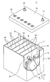
- the lead storage battery 1 includes a battery case 12 that accommodates an electrode plate group 11 and an electrolyte (not shown).
- the inside of the battery case 12 is partitioned into a plurality of cell chambers 14 by a partition wall 13.
- One electrode plate group 11 is accommodated in each cell chamber 14.
- the opening of the battery case 12 is closed by a lid 15 having a negative electrode terminal 16 and a positive electrode terminal 17.
- the lid 15 is provided with a liquid plug 18 for each cell chamber. At the time of rehydration, the liquid plug 18 is removed and refilling solution is replenished.
- the liquid plug 18 may have a function of discharging the gas generated in the cell chamber 14 out of the battery.
- the electrode plate group 11 is configured by laminating a plurality of negative electrode plates 2 and positive electrode plates 3 with a separator 4 interposed therebetween.
- the bag-like separator 4 which accommodates the negative electrode plate 2 is shown, the form of a separator is not specifically limited.
- the negative electrode shelf 6 connecting the plurality of negative electrode plates 2 in parallel is connected to the through connection body 8 and the positive electrode shelf connecting the plurality of positive electrode plates 3 in parallel 5 are connected to the positive pole 7.
- the positive electrode column 7 is connected to the external positive electrode terminal 17 of the lid 15.
- the negative electrode post 9 is connected to the negative electrode shelf 6, and the through connection body 8 is connected to the positive electrode shelf 5.
- the negative electrode post 9 is connected to the external negative electrode terminal 16 of the lid 15.
- the through connection members 8 pass through the through holes provided in the partition walls 13 to connect the electrode plate groups 11 of the adjacent cell chambers 14 in series.
- ⁇ Lead acid battery A1 (1) Preparation of Negative Electrode Plate
- Lead powder, water, dilute sulfuric acid, carbon black, and an organic shrink-proof agent were mixed to obtain a negative electrode paste.
- the negative electrode paste was filled in the mesh portion of an expanded lattice made of a Pb—Ca—Sn-based alloy as a negative electrode current collector, and was aged and dried to obtain an unformed negative electrode plate.
- Sodium lignin sulfonate was used as the organic plasticizer.
- the carbon black and the organic shrink-proof agent were added to the negative electrode paste by adjusting the addition amount such that the content contained in 100% by mass of the negative electrode material would be 0.3% by mass and 0.2% by mass, respectively. .
- Each unformed negative electrode plate is accommodated in a bag-shaped separator formed of a microporous polyethylene film, and seven unformed negative electrode plates and six unformed positive electrode plates per cell. Form an electrode group.
- the separator had a plurality of striped second ribs on the outside of the bag.
- the separator used was one in which the first rib was not provided on the inside of the bag.
- the plurality of second ribs are respectively formed along the height direction of the positive electrode plate, the average height of the second ribs is 0.4 mm, and the pitch of the second ribs in the region facing the positive electrode plate is It was 10 mm.
- the average thickness of the base portion of the separator was 200 ⁇ m.
- the electrode plate group is inserted into a polypropylene battery case, an electrolytic solution is injected, and formation is performed in the battery case, and a liquid lead-acid battery A1 having a nominal voltage of 12 V and a nominal capacity of 30 Ah (5 hour rate) Assembled.
- an electrolytic solution an aqueous solution containing sulfuric acid having a specific gravity of 1.28 at 20 ° C. was used.
- Lead-acid batteries A2 to A7 ⁇ In the preparation of the positive electrode plate, lead powder, water, an additive containing antimony (Sb), and sulfuric acid were kneaded to prepare a positive electrode paste. Antimony trioxide (Sb 2 O 3 ) was used as the additive containing antimony (Sb). The additive was used after adjusting the amount of Sb added such that the content contained in 100% by mass of the positive electrode material after formation was the mass% shown in Table 1. Other than this, lead storage batteries A2 to A7 were assembled in the same manner as the lead storage battery A1.
- Lead acid battery B1 As a separator, one having a first rib inside the bag was used.
- the separator has a plurality of stripe-shaped first ribs inside the bag, and the plurality of first ribs are respectively formed along the height direction of the negative electrode plate, and the average height of the first ribs is 0.
- the pitch of the first ribs was 1 mm in a region facing the negative electrode plate.
- the average height and pitch of the second ribs and the average thickness of the base of the separator are the same as those of the lead storage battery A1.
- a lead storage battery B1 was assembled in the same manner as the lead storage battery A1, except that separators provided with ribs on both the positive electrode plate side and the negative electrode plate side were used.
- Lead storage batteries B2 to B7 In the preparation of the positive electrode plate, lead powder, water, an additive containing antimony (Sb), and sulfuric acid were kneaded to prepare a positive electrode paste. The additive was used after adjusting the amount of Sb added such that the content contained in 100% by mass of the positive electrode material after formation was the mass% shown in Table 1. Other than this, lead storage batteries B2 to B7 were assembled in the same manner as the lead storage battery B1.
- Evaluation 2 Specific gravity difference measurement of electrolyte solution
- required was represented by the ratio when the specific gravity difference in lead acid battery A1 is set to 100. The smaller the specific gravity difference, the more the stratification is suppressed.
- evaluation 3 Osmotic short circuit
- the lead storage battery after evaluation by evaluation 1 was disassembled, the separator was taken out, and the presence or absence of the penetration trace of lead was confirmed.
- the surface facing the negative electrode of the separator was visually observed, and when a clear penetration mark of 1 mm or more could be confirmed, it was regarded as a penetration mark.
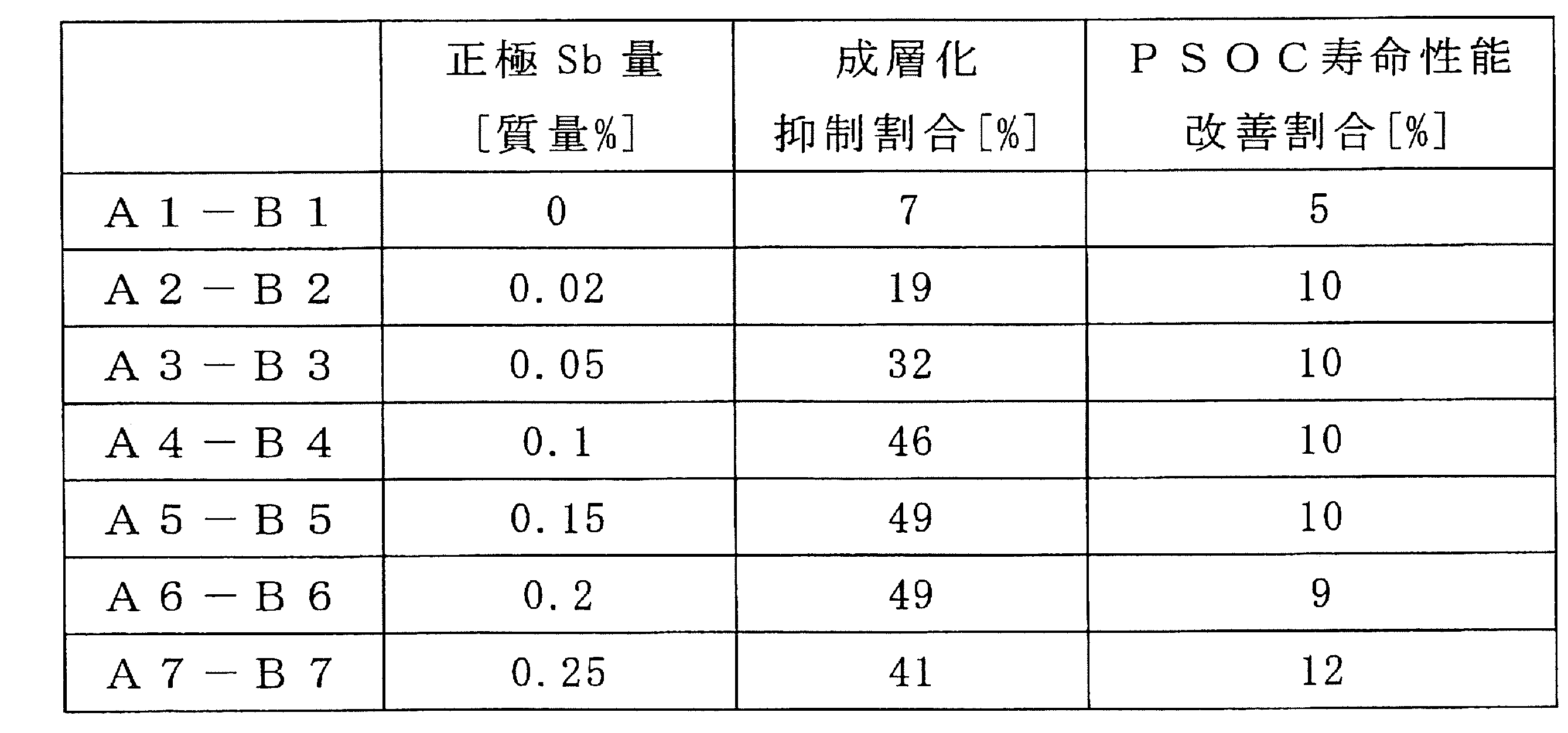
- the results of evaluations 1 to 3 of the lead storage batteries A1 to A7 and B1 to B7 are shown in Table 1.
- the separator is compared with the lead storage battery A1. No lead precipitation occurs, and the PSOC life performance is greatly improved.
- Lead storage batteries A1 and B1, A2 and B2, A3 and B3, A4 and B4, A5 and B5, A6 and B6, and A7 and B7 having the same Sb content are compared, respectively.
- the suppression ratio of stratification of the lead storage battery Y based on the lead storage battery X is 1- (difference between upper and lower specific gravity of the lead storage battery Y) / (upper and lower specific gravity difference of the lead storage battery X) Represented by
- the improvement rate of the PSOC life performance of the lead storage battery Y based on the lead storage battery X is represented by (the number of life cycles of the lead storage battery Y)) / (the number of life cycles of the lead storage battery X) -1.
- the upper and lower specific gravity differences of the electrolytic solution and the PSOC life performance are respectively minimum and maximum when the Sb content is 0.2% by mass. As the Sb content increases, the amount of liquid reduction due to gas generation also increases. By suppressing the Sb content to 0.2% by mass or less, it is possible to maximize the effect of improving the life performance while suppressing the amount of liquid reduction.
- the increase in liquid reduction amount which is a problem caused by containing Sb in the positive electrode material, is also significant. Is suppressed. As a result, the amount of liquid reduction can be reduced, and a lead-acid battery with significantly improved PSOC life performance can be realized.
- the lead storage battery according to one aspect of the present invention is applicable to control valve type and liquid lead storage batteries, and can be suitably used as a power source for starting a car or a motorcycle.
- Electrode plate group 12 Battery tank 13: Partition wall 14: cell chamber 15: lid 16: negative electrode terminal 17: positive electrode terminal 18: liquid port plug
Landscapes
- Chemical & Material Sciences (AREA)
- Chemical Kinetics & Catalysis (AREA)
- Electrochemistry (AREA)
- General Chemical & Material Sciences (AREA)
- Engineering & Computer Science (AREA)
- Manufacturing & Machinery (AREA)
- Secondary Cells (AREA)
- Cell Separators (AREA)
- Battery Electrode And Active Subsutance (AREA)
Abstract
Description
前記セパレータは、前記正極板側および前記負極板側にリブを備え、
前記正極電極材料は、Sbを0.02質量%以上含む、鉛蓄電池に関する。
なお、本明細書中、1CAとは電池の公称容量(Ah)と同じ数値の電流値(A)である。例えば、公称容量が30Ahの電池であれば、1CAは30Aであり、1mCAは30mAである。
セパレータは、微多孔膜で構成されたベース部と、ベース部の一方の主面から突出するリブと、ベース部の他方の主面から突出するリブとを備える。ベース部の一方の主面から突出するリブは、負極板側に位置するように配置される。この負極板側に位置するリブを第1リブと呼ぶ。ベース部の他方の主面から突出するリブは、正極板側(つまり、正極板に対向するよう)に配置される。この正極板側に位置するリブを第2リブと呼ぶ。第1リブにより負極板近傍における電解液の拡散性を高めることができるため、PSOC寿命性能をさらに向上することができるとともに、浸透短絡を抑制できる。
ベース部の平均厚みは、セパレータの断面写真において、任意に選択した5箇所についてベース部の厚みを計測し、平均化することにより求められる。
第1リブの平均ピッチは、任意に選択される10箇所において計測した第1リブのピッチを平均化することにより求められる。なお、負極板と対向しない領域に第1リブが密に形成されている場合には、この領域を除いて平均ピッチを算出すればよい。負極板と対向しない領域の第1リブの平均ピッチは、この領域について上記と同様に算出できる。
なお、第2リブの平均高さは、第1リブの場合に準じて求められる。第2リブの高さは、第1リブの場合に準じて、第2リブの所定の位置におけるベース部の他方の主面から第2リブの頂部までの距離を言う。
なお、第2リブのピッチとは、隣接する第2リブの頂部間距離(より具体的には、第2リブを横切る方向における隣接する第2リブの中心間距離)である。第2リブの平均ピッチは、第1リブの平均ピッチに準じて算出できる。
電解液は、水溶液に硫酸を含む。電解液は、必要に応じてゲル化させてもよい。電解液は、必要に応じて、鉛蓄電池に利用される添加剤を含むことができる。
化成後で満充電状態の鉛蓄電池における電解液の20℃における比重は、例えば、1.10g/cm3以上1.35g/cm3以下である。
鉛蓄電池の正極板には、ペースト式とクラッド式がある。
ペースト式正極板は、正極集電体と、正極電極材料とを具備する。正極電極材料は、正極集電体に保持されている。ペースト式正極板では、正極電極材料は、正極板から正極集電体を除いたものである。正極集電体は、負極集電体と同様に形成すればよく、鉛または鉛合金の鋳造や、鉛または鉛合金シートの加工により形成することができる。
未化成のクラッド式正極板は、芯金が挿入されたチューブに、添加剤と鉛粉またはスラリー状の鉛粉とを混合し、混合物を充填し、複数のチューブを連座で結合することにより形成される。
鉛蓄電池の負極板は、負極集電体と、負極電極材料とで構成されている。負極電極材料は、負極板から負極集電体を除いたものである。負極集電体は、鉛(Pb)または鉛合金の鋳造により形成してもよく、鉛または鉛合金シートを加工して形成してもよい。加工方法としては、例えば、エキスパンド加工や打ち抜き(パンチング)加工が挙げられる。負極集電体として負極格子を用いると、負極電極材料を担持させ易いため好ましい。
鉛蓄電池は、さらに、正極板と負極板との間に介在する繊維マットを備えていてもよい。繊維マットを配置する場合には、電極板が繊維マットで圧迫されて、電極板の周囲に電解液を保持し難くなる。本発明の上記側面では、セパレータに第1リブを設けるため、負極板近傍に電解液を確保し易くなり、電解液の高い拡散性を確保することができる。
鉛蓄電池1は、極板群11と電解液(図示せず)とを収容する電槽12を具備する。電槽12内は、隔壁13により、複数のセル室14に仕切られている。各セル室14には、極板群11が1つずつ収納されている。電槽12の開口部は、負極端子16および正極端子17を具備する蓋15で閉じられる。蓋15には、セル室毎に液口栓18が設けられている。補水の際には、液口栓18を外して補水液が補給される。液口栓18は、セル室14内で発生したガスを電池外に排出する機能を有してもよい。
以下、本発明を実施例および比較例に基づいて具体的に説明するが、本発明は以下の実施例に限定されるものではない。
(1)負極板の作製
鉛粉、水、希硫酸、カーボンブラック、有機防縮剤を混合して、負極ペーストを得た。負極ペーストを、負極集電体としてのPb-Ca-Sn系合金製のエキスパンド格子の網目部に充填し、熟成、乾燥し、未化成の負極板を得た。有機防縮剤には、リグニンスルホン酸ナトリウムを用いた。カーボンブラックおよび有機防縮剤は、それぞれ、負極電極材料100質量%に含まれる含有量が0.3質量%および0.2質量%となるように、添加量を調整して、負極ペーストに配合した。
鉛粉と、水と、硫酸とを混練させて、正極ペーストを作製した。正極ペーストを、正極集電体としてのPb-Ca-Sn系合金製のエキスパンド格子の網目部に充填し、熟成、乾燥し、未化成の正極板を得た。
未化成の各負極板を、ポリエチレン製の微多孔膜で形成された袋状セパレータに収容し、セル当たり未化成の負極板7枚と未化成の正極板6枚とで極板群を形成した。セパレータは、袋の外側に、ストライプ状の第2リブを複数有していた。セパレータは、袋の内側に第1リブが設けられていないものを用いた。複数の第2リブは、それぞれ、正極板の高さ方向に沿って形成され、第2リブの平均高さは、0.4mmであり、正極板に対向する領域において第2リブのピッチは、10mmであった。また、セパレータのベース部の平均厚みは、200μmであった。
正極板の作製において、鉛粉と、水と、アンチモン(Sb)を含む添加剤と、硫酸とを混練させて、正極ペーストを作製した。アンチモン(Sb)を含む添加剤は、三酸化アンチモン(Sb2O3)を用いた。添加剤は、化成後の正極電極材料100質量%に含まれる含有量が、表1で示される質量%となるように、Sb添加量を調整したものを用いた。これ以外については、鉛蓄電池A1と同様にして鉛蓄電池A2~A7を組み立てた。
セパレータとして、袋の内側に第1リブを有するものを用いた。セパレータは、袋の内側に、ストライプ状の第1リブを複数有し、複数の第1リブは、それぞれ、負極板の高さ方向に沿って形成され、第1リブの平均高さは、0.1mmであり、負極板に対向する領域において第1リブのピッチは、1mmであった。第2リブの平均高さおよびピッチ、ならびに、セパレータのベース部の平均厚みについては、鉛蓄電池A1と同様である。
正極板の作製において、鉛粉と、水と、アンチモン(Sb)を含む添加剤と、硫酸とを混練させて、正極ペーストを作製した。添加剤は、化成後の正極電極材料100質量%に含まれる含有量が、表1で示される質量%となるように、Sb添加量を調整したものを用いた。これ以外については、鉛蓄電池B1と同様にして鉛蓄電池B2~B7を組み立てた。
SBA S 0101:2014に準拠して、アイドリングストップ条件で、鉛蓄電池の充放電を行った。具体的には、25℃において、下記の(a)~(c)を1サイクルとして、放電末電圧が7.2V以下になるまで繰り返し、このときのサイクル数を求めた。鉛蓄電池A1におけるサイクル数を100としたときの比率でPSOC寿命性能を評価した。なお、充放電時には、3600サイクル毎に40時間~48時間休止した。
(a)放電1:32Aの電流値で59秒放電する。
(b)放電2:300Aの電流値で1秒間放電する。
(c)充電:制限電流100Aおよび14.0Vの電圧で60秒間充電する。
評価1において、18000サイクル経過後の電解液の上部(液面から30mm下方)と下部(電槽の底から10mm上方)の比重を求め、比重差を求めた。求めた比重差を、鉛蓄電池A1における比重差を100としたときの比率で表した。比重差が小さいほど、成層化が抑制されていることを意味する。
評価1で評価した後の鉛蓄電池を分解し、セパレータを取り出して、鉛の浸透痕の有無を確認した。セパレータの負極と対向する面を目視し、1mm以上の明確な浸透痕を確認できた場合に浸透痕有とした。
鉛蓄電池A1~A7およびB1~B7の評価1~3の結果を表1に示す。
評価1で寿命となった電池質量と評価1を行う前の電池質量との差を求め、当該差をPSOC寿命のサイクル数で除算し、1サイクル当りの減液量を求めた。求めた1サイクル当りの減液量を、鉛蓄電池A1における1サイクル当りの減液量を100としたときの比率で表した。1サイクル当りの減液量が小さいほど、減液が抑制されていることを意味する。

2:負極板
3:正極板
4:セパレータ
5:正極棚部
6:負極棚部
7:正極柱
8:貫通接続体
9:負極柱
11:極板群
12:電槽
13:隔壁
14:セル室
15:蓋
16:負極端子
17:正極端子
18:液口栓
Claims (6)
- 正極電極材料が設けられた正極板と、負極板と、正極板および負極板の間に介在するセパレータと、電解液とを備え、
前記セパレータは、前記正極板側および前記負極板側にリブを備え、
前記正極電極材料は、Sbを0.02質量%以上含む、鉛蓄電池。 - 前記正極電極材料は、Sbを0.02質量%以上0.2質量%以下の範囲で含む、請求項1に記載の鉛蓄電池。
- 前記正極電極材料は、Sbを0.02質量%以上0.1質量%以下の範囲で含む、請求項2に記載の鉛蓄電池。
- 前記セパレータは、袋状である、請求項1~3のいずれか1項に記載の鉛蓄電池。
- 前記セパレータは、前記負極板を収容している、請求項4に記載の鉛蓄電池。
- 前記セパレータは、前記正極板を収容している、請求項4に記載の鉛蓄電池。
Priority Applications (3)
| Application Number | Priority Date | Filing Date | Title |
|---|---|---|---|
| EP18874711.7A EP3683887A4 (en) | 2017-10-31 | 2018-10-05 | LEAD ACCUMULATOR |
| JP2019550928A JPWO2019087678A1 (ja) | 2017-10-31 | 2018-10-05 | 鉛蓄電池 |
| CN201880070408.2A CN111279540A (zh) | 2017-10-31 | 2018-10-05 | 铅蓄电池 |
Applications Claiming Priority (2)
| Application Number | Priority Date | Filing Date | Title |
|---|---|---|---|
| JP2017-211357 | 2017-10-31 | ||
| JP2017211357 | 2017-10-31 |
Publications (1)
| Publication Number | Publication Date |
|---|---|
| WO2019087678A1 true WO2019087678A1 (ja) | 2019-05-09 |
Family
ID=66333135
Family Applications (1)
| Application Number | Title | Priority Date | Filing Date |
|---|---|---|---|
| PCT/JP2018/037297 Ceased WO2019087678A1 (ja) | 2017-10-31 | 2018-10-05 | 鉛蓄電池 |
Country Status (4)
| Country | Link |
|---|---|
| EP (1) | EP3683887A4 (ja) |
| JP (1) | JPWO2019087678A1 (ja) |
| CN (1) | CN111279540A (ja) |
| WO (1) | WO2019087678A1 (ja) |
Cited By (4)
| Publication number | Priority date | Publication date | Assignee | Title |
|---|---|---|---|---|
| WO2021060327A1 (ja) * | 2019-09-27 | 2021-04-01 | 株式会社Gsユアサ | 鉛蓄電池 |
| WO2021084878A1 (ja) * | 2019-10-28 | 2021-05-06 | 株式会社Gsユアサ | 鉛蓄電池 |
| CN113013410A (zh) * | 2019-12-20 | 2021-06-22 | 株式会社杰士汤浅国际 | 铅蓄电池 |
| JP2021099920A (ja) * | 2019-12-20 | 2021-07-01 | 株式会社Gsユアサ | 鉛蓄電池 |
Citations (8)
| Publication number | Priority date | Publication date | Assignee | Title |
|---|---|---|---|---|
| JPS5717062U (ja) * | 1980-07-02 | 1982-01-28 | ||
| JPH03274668A (ja) * | 1990-03-23 | 1991-12-05 | Japan Storage Battery Co Ltd | 密閉式鉛蓄電池 |
| JPH07105929A (ja) * | 1993-09-30 | 1995-04-21 | Matsushita Electric Ind Co Ltd | 鉛蓄電池 |
| JP2013541162A (ja) * | 2010-09-22 | 2013-11-07 | ダラミック エルエルシー | 改良された鉛蓄電池セパレータ、電池及び関連の方法 |
| JP2015216125A (ja) | 2015-07-27 | 2015-12-03 | 日本板硝子株式会社 | 液式鉛蓄電池用セパレータおよび液式鉛蓄電池 |
| JP2016189296A (ja) * | 2015-03-30 | 2016-11-04 | 株式会社Gsユアサ | 鉛蓄電池 |
| JP2017063001A (ja) * | 2015-09-25 | 2017-03-30 | 株式会社Gsユアサ | 鉛蓄電池 |
| JP2017195100A (ja) * | 2016-04-21 | 2017-10-26 | 株式会社Gsユアサ | 鉛蓄電池 |
Family Cites Families (5)
| Publication number | Priority date | Publication date | Assignee | Title |
|---|---|---|---|---|
| JP5532245B2 (ja) * | 2010-09-30 | 2014-06-25 | 株式会社Gsユアサ | 鉛蓄電池及びその製造方法 |
| WO2013150754A1 (ja) * | 2012-04-06 | 2013-10-10 | 株式会社Gsユアサ | 液式鉛蓄電池 |
| JP6176180B2 (ja) * | 2013-07-19 | 2017-08-09 | 株式会社Gsユアサ | 液式鉛蓄電池及び液式鉛蓄電池を用いたアイドリングストップ車 |
| JP6153074B2 (ja) * | 2013-08-02 | 2017-06-28 | 株式会社Gsユアサ | 液式鉛蓄電池 |
| JP6307043B2 (ja) * | 2015-05-20 | 2018-04-04 | 株式会社Gsユアサ | 液式鉛蓄電池 |
-
2018
- 2018-10-05 CN CN201880070408.2A patent/CN111279540A/zh active Pending
- 2018-10-05 JP JP2019550928A patent/JPWO2019087678A1/ja active Pending
- 2018-10-05 EP EP18874711.7A patent/EP3683887A4/en not_active Withdrawn
- 2018-10-05 WO PCT/JP2018/037297 patent/WO2019087678A1/ja not_active Ceased
Patent Citations (8)
| Publication number | Priority date | Publication date | Assignee | Title |
|---|---|---|---|---|
| JPS5717062U (ja) * | 1980-07-02 | 1982-01-28 | ||
| JPH03274668A (ja) * | 1990-03-23 | 1991-12-05 | Japan Storage Battery Co Ltd | 密閉式鉛蓄電池 |
| JPH07105929A (ja) * | 1993-09-30 | 1995-04-21 | Matsushita Electric Ind Co Ltd | 鉛蓄電池 |
| JP2013541162A (ja) * | 2010-09-22 | 2013-11-07 | ダラミック エルエルシー | 改良された鉛蓄電池セパレータ、電池及び関連の方法 |
| JP2016189296A (ja) * | 2015-03-30 | 2016-11-04 | 株式会社Gsユアサ | 鉛蓄電池 |
| JP2015216125A (ja) | 2015-07-27 | 2015-12-03 | 日本板硝子株式会社 | 液式鉛蓄電池用セパレータおよび液式鉛蓄電池 |
| JP2017063001A (ja) * | 2015-09-25 | 2017-03-30 | 株式会社Gsユアサ | 鉛蓄電池 |
| JP2017195100A (ja) * | 2016-04-21 | 2017-10-26 | 株式会社Gsユアサ | 鉛蓄電池 |
Non-Patent Citations (1)
| Title |
|---|
| See also references of EP3683887A4 |
Cited By (12)
| Publication number | Priority date | Publication date | Assignee | Title |
|---|---|---|---|---|
| WO2021060327A1 (ja) * | 2019-09-27 | 2021-04-01 | 株式会社Gsユアサ | 鉛蓄電池 |
| JPWO2021060327A1 (ja) * | 2019-09-27 | 2021-04-01 | ||
| JP2024059783A (ja) * | 2019-09-27 | 2024-05-01 | 株式会社Gsユアサ | 鉛蓄電池 |
| JP7505499B2 (ja) | 2019-09-27 | 2024-06-25 | 株式会社Gsユアサ | 鉛蓄電池 |
| WO2021084878A1 (ja) * | 2019-10-28 | 2021-05-06 | 株式会社Gsユアサ | 鉛蓄電池 |
| JPWO2021084878A1 (ja) * | 2019-10-28 | 2021-05-06 | ||
| JP7533474B2 (ja) | 2019-10-28 | 2024-08-14 | 株式会社Gsユアサ | 鉛蓄電池 |
| CN113013410A (zh) * | 2019-12-20 | 2021-06-22 | 株式会社杰士汤浅国际 | 铅蓄电池 |
| JP2021099921A (ja) * | 2019-12-20 | 2021-07-01 | 株式会社Gsユアサ | 鉛蓄電池 |
| JP2021099920A (ja) * | 2019-12-20 | 2021-07-01 | 株式会社Gsユアサ | 鉛蓄電池 |
| JP7419794B2 (ja) | 2019-12-20 | 2024-01-23 | 株式会社Gsユアサ | 鉛蓄電池 |
| JP7424037B2 (ja) | 2019-12-20 | 2024-01-30 | 株式会社Gsユアサ | 鉛蓄電池 |
Also Published As
| Publication number | Publication date |
|---|---|
| EP3683887A1 (en) | 2020-07-22 |
| JPWO2019087678A1 (ja) | 2020-11-19 |
| EP3683887A4 (en) | 2021-06-30 |
| CN111279540A (zh) | 2020-06-12 |
Similar Documents
| Publication | Publication Date | Title |
|---|---|---|
| JP7255492B2 (ja) | 鉛蓄電池 | |
| JP7380580B2 (ja) | 鉛蓄電池 | |
| JP7355005B6 (ja) | 鉛蓄電池 | |
| WO2019087678A1 (ja) | 鉛蓄電池 | |
| JP2020161409A (ja) | 液式鉛蓄電池用セパレータおよび液式鉛蓄電池 | |
| JP7375457B2 (ja) | 鉛蓄電池 | |
| WO2019087685A1 (ja) | 鉛蓄電池の製造方法 | |
| WO2019021692A1 (ja) | 鉛蓄電池 | |
| JP7147776B2 (ja) | 鉛蓄電池 | |
| WO2019087684A1 (ja) | アイドリングストップ用鉛蓄電池 | |
| CN111279543B (zh) | 铅蓄电池 | |
| WO2019087683A1 (ja) | 鉛蓄電池 | |
| JP7167934B2 (ja) | 鉛蓄電池 | |
| JP6750376B2 (ja) | 鉛蓄電池 | |
| JP7476510B2 (ja) | 鉛蓄電池 | |
| JP2024005293A (ja) | 鉛蓄電池 | |
| WO2023210636A1 (ja) | 鉛蓄電池 | |
| WO2023210635A1 (ja) | 鉛蓄電池 | |
| JP2025095289A (ja) | 鉛蓄電池およびその製造方法 | |
| JP2017069010A (ja) | 鉛蓄電池 | |
| JP2025012336A (ja) | 鉛蓄電池用正極板、鉛蓄電池用負極板、および鉛蓄電池 |
Legal Events
| Date | Code | Title | Description |
|---|---|---|---|
| 121 | Ep: the epo has been informed by wipo that ep was designated in this application |
Ref document number: 18874711 Country of ref document: EP Kind code of ref document: A1 |
|
| ENP | Entry into the national phase |
Ref document number: 2019550928 Country of ref document: JP Kind code of ref document: A |
|
| ENP | Entry into the national phase |
Ref document number: 2018874711 Country of ref document: EP Effective date: 20200416 |
|
| NENP | Non-entry into the national phase |
Ref country code: DE |
|
| WWW | Wipo information: withdrawn in national office |
Ref document number: 2018874711 Country of ref document: EP |