WO2019092826A1 - 処理方法 - Google Patents
処理方法 Download PDFInfo
- Publication number
- WO2019092826A1 WO2019092826A1 PCT/JP2017/040376 JP2017040376W WO2019092826A1 WO 2019092826 A1 WO2019092826 A1 WO 2019092826A1 JP 2017040376 W JP2017040376 W JP 2017040376W WO 2019092826 A1 WO2019092826 A1 WO 2019092826A1
- Authority
- WO
- WIPO (PCT)
- Prior art keywords
- battery pack
- slag
- processing method
- pan
- battery
- Prior art date
- Legal status (The legal status is an assumption and is not a legal conclusion. Google has not performed a legal analysis and makes no representation as to the accuracy of the status listed.)
- Ceased
Links
Images



Classifications
-
- C—CHEMISTRY; METALLURGY
- C21—METALLURGY OF IRON
- C21B—MANUFACTURE OF IRON OR STEEL
- C21B3/00—General features in the manufacture of pig-iron
- C21B3/04—Recovery of by-products, e.g. slag
-
- C—CHEMISTRY; METALLURGY
- C21—METALLURGY OF IRON
- C21B—MANUFACTURE OF IRON OR STEEL
- C21B3/00—General features in the manufacture of pig-iron
- C21B3/04—Recovery of by-products, e.g. slag
- C21B3/06—Treatment of liquid slag
- C21B3/10—Slag pots; Slag cars
-
- C—CHEMISTRY; METALLURGY
- C21—METALLURGY OF IRON
- C21C—PROCESSING OF PIG-IRON, e.g. REFINING, MANUFACTURE OF WROUGHT-IRON OR STEEL; TREATMENT IN MOLTEN STATE OF FERROUS ALLOYS
- C21C5/00—Manufacture of carbon-steel, e.g. plain mild steel, medium carbon steel or cast steel or stainless steel
- C21C5/52—Manufacture of steel in electric furnaces
-
- C—CHEMISTRY; METALLURGY
- C21—METALLURGY OF IRON
- C21C—PROCESSING OF PIG-IRON, e.g. REFINING, MANUFACTURE OF WROUGHT-IRON OR STEEL; TREATMENT IN MOLTEN STATE OF FERROUS ALLOYS
- C21C5/00—Manufacture of carbon-steel, e.g. plain mild steel, medium carbon steel or cast steel or stainless steel
- C21C5/52—Manufacture of steel in electric furnaces
- C21C5/5264—Manufacture of alloyed steels including ferro-alloys
-
- C—CHEMISTRY; METALLURGY
- C21—METALLURGY OF IRON
- C21C—PROCESSING OF PIG-IRON, e.g. REFINING, MANUFACTURE OF WROUGHT-IRON OR STEEL; TREATMENT IN MOLTEN STATE OF FERROUS ALLOYS
- C21C5/00—Manufacture of carbon-steel, e.g. plain mild steel, medium carbon steel or cast steel or stainless steel
- C21C5/52—Manufacture of steel in electric furnaces
- C21C5/527—Charging of the electric furnace
-
- C—CHEMISTRY; METALLURGY
- C22—METALLURGY; FERROUS OR NON-FERROUS ALLOYS; TREATMENT OF ALLOYS OR NON-FERROUS METALS
- C22B—PRODUCTION AND REFINING OF METALS; PRETREATMENT OF RAW MATERIALS
- C22B7/00—Working up raw materials other than ores, e.g. scrap, to produce non-ferrous metals and compounds thereof; Methods of a general interest or applied to the winning of more than two metals
-
- H—ELECTRICITY
- H01—ELECTRIC ELEMENTS
- H01M—PROCESSES OR MEANS, e.g. BATTERIES, FOR THE DIRECT CONVERSION OF CHEMICAL ENERGY INTO ELECTRICAL ENERGY
- H01M10/00—Secondary cells; Manufacture thereof
- H01M10/54—Reclaiming serviceable parts of waste accumulators
-
- H—ELECTRICITY
- H01—ELECTRIC ELEMENTS
- H01M—PROCESSES OR MEANS, e.g. BATTERIES, FOR THE DIRECT CONVERSION OF CHEMICAL ENERGY INTO ELECTRICAL ENERGY
- H01M6/00—Primary cells; Manufacture thereof
- H01M6/52—Reclaiming serviceable parts of waste cells or batteries, e.g. recycling
-
- C—CHEMISTRY; METALLURGY
- C21—METALLURGY OF IRON
- C21B—MANUFACTURE OF IRON OR STEEL
- C21B2400/00—Treatment of slags originating from iron or steel processes
- C21B2400/02—Physical or chemical treatment of slags
-
- C—CHEMISTRY; METALLURGY
- C21—METALLURGY OF IRON
- C21B—MANUFACTURE OF IRON OR STEEL
- C21B2400/00—Treatment of slags originating from iron or steel processes
- C21B2400/05—Apparatus features
- C21B2400/066—Receptacle features where the slag is treated
- C21B2400/07—Receptacle features where the slag is treated open to atmosphere
-
- C—CHEMISTRY; METALLURGY
- C21—METALLURGY OF IRON
- C21C—PROCESSING OF PIG-IRON, e.g. REFINING, MANUFACTURE OF WROUGHT-IRON OR STEEL; TREATMENT IN MOLTEN STATE OF FERROUS ALLOYS
- C21C2200/00—Recycling of waste material
-
- Y—GENERAL TAGGING OF NEW TECHNOLOGICAL DEVELOPMENTS; GENERAL TAGGING OF CROSS-SECTIONAL TECHNOLOGIES SPANNING OVER SEVERAL SECTIONS OF THE IPC; TECHNICAL SUBJECTS COVERED BY FORMER USPC CROSS-REFERENCE ART COLLECTIONS [XRACs] AND DIGESTS
- Y02—TECHNOLOGIES OR APPLICATIONS FOR MITIGATION OR ADAPTATION AGAINST CLIMATE CHANGE
- Y02P—CLIMATE CHANGE MITIGATION TECHNOLOGIES IN THE PRODUCTION OR PROCESSING OF GOODS
- Y02P10/00—Technologies related to metal processing
- Y02P10/20—Recycling
-
- Y—GENERAL TAGGING OF NEW TECHNOLOGICAL DEVELOPMENTS; GENERAL TAGGING OF CROSS-SECTIONAL TECHNOLOGIES SPANNING OVER SEVERAL SECTIONS OF THE IPC; TECHNICAL SUBJECTS COVERED BY FORMER USPC CROSS-REFERENCE ART COLLECTIONS [XRACs] AND DIGESTS
- Y02—TECHNOLOGIES OR APPLICATIONS FOR MITIGATION OR ADAPTATION AGAINST CLIMATE CHANGE
- Y02W—CLIMATE CHANGE MITIGATION TECHNOLOGIES RELATED TO WASTEWATER TREATMENT OR WASTE MANAGEMENT
- Y02W30/00—Technologies for solid waste management
- Y02W30/50—Reuse, recycling or recovery technologies
-
- Y—GENERAL TAGGING OF NEW TECHNOLOGICAL DEVELOPMENTS; GENERAL TAGGING OF CROSS-SECTIONAL TECHNOLOGIES SPANNING OVER SEVERAL SECTIONS OF THE IPC; TECHNICAL SUBJECTS COVERED BY FORMER USPC CROSS-REFERENCE ART COLLECTIONS [XRACs] AND DIGESTS
- Y02—TECHNOLOGIES OR APPLICATIONS FOR MITIGATION OR ADAPTATION AGAINST CLIMATE CHANGE
- Y02W—CLIMATE CHANGE MITIGATION TECHNOLOGIES RELATED TO WASTEWATER TREATMENT OR WASTE MANAGEMENT
- Y02W30/00—Technologies for solid waste management
- Y02W30/50—Reuse, recycling or recovery technologies
- Y02W30/84—Recycling of batteries or fuel cells
Definitions
- the present disclosure relates to a processing method.
- the battery pack contains valuable metals. Therefore, valuable metals are recovered from used battery packs and recycled (recycled).
- the battery pack is used for the battery body (battery unit), the resin that constitutes the lid, etc., the metal member that constitutes the housing, etc., electronic components such as relays and boards, and the wire harness (wiring). It is disassembled. Subsequently, the disassembled parts (modules) are subjected to processing appropriate for the respective parts.
- the above-described method of processing the battery pack has a problem that it takes time and man-hours to disassemble it into parts.
- the battery pack includes a battery main body to which high voltage power is output, the worker is forced to perform complicated work of wearing protective tools etc. to prevent electric shock at the time of disassembly. .
- the present disclosure aims to provide a processing method capable of easily processing a battery pack.
- a processing method concerning one mode of this indication is a processing method of a battery pack which contains a battery main part and resin at least, and covers a battery pack with slag of predetermined temperature.
- the battery pack may be covered with a slag, including the step of containing the battery pack in the containing part.
- the storage portion may be a slag pan that receives slag discharged from the electric furnace.
- the slag pan may have an inner bottom surface formed in an arc.
- a step may be formed on the inner bottom surface.
- a plate in which one or more holes are formed may be provided in the inner space.
- the housing portion may be a hole formed on the ground.
- the predetermined temperature may be 700 ° C. or more.
- the battery pack can be easily processed.
- FIG. 3A is a first diagram illustrating a process flow of the battery pack processing method according to the first embodiment.
- FIG. 3B is a second diagram illustrating the process flow of the battery pack processing method according to the first embodiment.
- FIG. 3C is a third diagram illustrating the process flow of the battery pack processing method according to the first embodiment.
- FIG. 4A is a fourth diagram illustrating a process flow of the battery pack processing method according to the first embodiment.
- FIG. 4B is a fifth diagram illustrating a process flow of the battery pack processing method according to the first embodiment. It is a figure explaining the slag pan of 1st Embodiment.
- FIG. 7A is a first diagram for explaining the flow of processing of the battery pack processing method according to the second embodiment.
- FIG. 7B is a second diagram illustrating the process flow of the battery pack processing method according to the second embodiment.
- FIG. 8A is a view for explaining a slag pan of a first modified example.
- FIG. 8B is a view for explaining a slag pan of a second modified example.
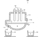
- FIG. 1 is a diagram for explaining an electric furnace 100. As shown in FIG. As shown in FIG. 1, the electric furnace 100 includes a furnace body 110, a furnace lid 120, and an electrode 130.
- An object to be melted (for example, iron scrap) is charged (charged) into the furnace body 110.
- a steel outlet 112 is formed at the bottom of the furnace body 110.
- the steel outlet 112 is sealed by a plug 112a.
- a slag discharge port 114 is formed on the side wall of the furnace body 110. The slag discharge port 114 is opened and closed by a door 114a.
- the furnace lid 120 seals the opening formed at the top of the furnace body 110.
- the furnace cover 120 is detachably provided to the furnace body 110.
- a plurality of (here three) electrodes 130 are provided.
- the electrode 130 is disposed in the furnace body 110 through the furnace lid 120. Electric power is supplied to the electrode 130 from a power supply (not shown), and an alternating voltage is applied between the electrodes 130.
- the application of a voltage to the electrode 130 causes an arc discharge.
- the object to be melted which is introduced into the furnace body 110, is heated (arc heating), and the object to be melted is melted.
- the molten metal M and the slag S are generated.
- the molten metal M and the slag S are separated due to the specific gravity difference.
- the molten metal M is located below the slag S.
- the molten metal M is tapped from the tapping hole 112.
- the molten metal M extracted is stored in the steel receiving pan 140.
- the molten metal M stored in the steel receiving pan 140 is conveyed to a processing facility at a subsequent stage, and then cast or rolled to be processed into a steel product (for example, a bar).
- the slag S is discharged from the slag outlet 114.
- the discharged slag S is stored in the slag pan 150.
- the slag S stored in the slag pan 150 is cooled and used as a roadbed material or particulate aggregate.
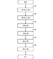
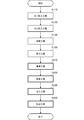
- FIG. 2 is a flowchart for explaining the process flow of the method of processing the battery pack BP according to the first embodiment.
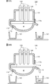
- FIG. 3A is a first diagram illustrating a process flow of the method of processing the battery pack BP according to the first embodiment.
- FIG. 3B is a second diagram illustrating the process flow of the battery pack processing method according to the first embodiment.
- FIG. 3C is a third diagram illustrating the process flow of the battery pack processing method according to the first embodiment.
- FIG. 4A is a fourth diagram illustrating a process flow of the battery pack processing method according to the first embodiment.
- FIG. 4B is a fifth diagram illustrating the process flow of the method of processing the battery pack BP according to the first embodiment.
- the processing method of the present embodiment includes a first charging step S110, a second charging step S120, a heating step S130, a storage step S140, a discharging step S150, and a removing step S160.
- the first charging step S110 is a step of charging one or more battery packs BP as they are (without disassembly) into the furnace body 110 of the electric furnace 100.
- the battery pack BP includes not only a battery body (battery unit) but also a resin that constitutes a lid or the like, a metal member that constitutes a housing or the like, an electronic component such as a relay or a substrate, and a wire harness (wiring).
- the mass of the battery pack BP is, for example, about 40 kg to 400 kg.
- the furnace lid 120 is removed, and as shown in FIG. 3A, the battery pack BP is charged into the furnace body 110.
- the second charging step S120 is a step of charging a material containing iron onto the battery pack BP.
- the material containing iron is, for example, iron scrap (dust iron) FS.
- iron scrap FS is charged onto the battery pack BP in the furnace main body 110.
- Heating step S130 is a step of heating battery pack BP and iron scrap FS.
- the furnace body 110 is sealed by the furnace lid 120, and power is supplied from a power supply (not shown) to the electrode 130 for a predetermined time (for example, about 30 minutes). Thereby, an alternating voltage is applied between the electrodes 130 to cause arc discharge, and the iron scrap FS and the battery pack BP are heated and melted.
- the heating temperature in the furnace body 110 is 2000 ° C. or more (eg, about 3000 ° C.). Thereby, molten metal M and slag S are generated.
- the metal contained in the iron scrap FS and the metal contained in the battery pack BP are the molten metal M.
- the metal can be taken out from the battery pack BP by an easy process such as simply putting the battery pack BP into the electric furnace 100 for producing steelmaking from the iron scrap FS as it is.
- an easy process such as simply putting the battery pack BP into the electric furnace 100 for producing steelmaking from the iron scrap FS as it is.
- it is not necessary to disassemble the battery pack BP and the time and man-hours required for the processing of the battery pack BP can be reduced.
- the worker is compelled to carry out complicated work such as wearing protective equipment etc. Can be avoided.
- the resin contained in the battery pack BP functions as a reducing agent in the furnace body 110.
- the quantity of the reducing agent for example, coke
- the battery pack BP when the battery pack BP is put into the furnace body 110, it is possible to reduce the amount of CO 2 emission at the time of reduction reaction.
- the resin does not need to be disposed (finally disposed) in final disposal, and the cost required to dispose the resin can be reduced.
- non-ferrous metals other than iron for example, copper, nickel, cobalt, aluminum, etc.
- the battery pack BP is put into the furnace body 110 in addition to the iron scrap FS. Therefore, it is possible to reduce the amount of nonferrous metals separately supplied by the amount of nonferrous metals contained in the battery pack BP. Further, compared with the prior art for disassembling the battery pack BP, there is no need to smelt aluminum, power required for aluminum smelting can be reduced, and CO 2 emissions generated at the time of smelting can be reduced. It becomes possible.
- the iron scrap FS can be placed on the battery pack BP in the furnace body 110 by performing the first charging step S110 and the second charging step S120. Thereby, the iron scrap FS can be functioned as a weight, and the situation where the battery pack BP floats up in the heating step S130 can be avoided. Further, the iron scrap FS makes it possible to prevent the water vapor explosion of the battery pack BP.
- the accommodation step S140 is a step of accommodating one or a plurality of battery packs BP in the slag pan 150 (housing portion), as shown in FIG. 4A.
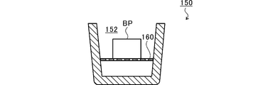
- FIG. 5 is a view for explaining the slag pan 150 of the first embodiment.
- a plate 160 is provided in the internal space 152 of the slag pan 150.
- the plate 160 divides the internal space 152 of the slag pan 150 vertically.
- the plate 160 is formed with one or more holes.
- the holes are sized so that the battery pack BP can not pass easily or can not pass.
- the shape of the hole is not limited, and is, for example, a slit, a rectangle, or a circle.
- the plate 160 is, for example, a steel net.
- the accommodation step S140 one or more battery packs BP are accommodated (placed) on the plate 160. Therefore, a space is formed below the plate 160 in the internal space 152 of the slag pan 150.
- the discharging step S150 is a step of discharging the slag S and the molten metal M from the furnace body 110.
- the discharge step S150 first, the door 114a is moved to open the slag discharge port 114. Then, the slag S is discharged from the furnace body 110 through the slag discharge port 114. The discharged slag S is supplied to the slag pan 150.
- the storage step S140 since the battery pack BP is stored in the slag pan 150, the battery pack BP is covered with the slag S in the slag pan 150.
- emitted from the slag discharge port 114 is 1000 degreeC or more (for example, 1200 degreeC or more and less than 1400 degreeC). Therefore, by covering the battery pack BP with the slag S, the resin contained in the battery pack BP is sublimated (vaporized). Therefore, the resin can be removed from the battery pack BP, and only the metal (metal piece) can be used.
- “covering” includes meaning that the slag S is applied to the battery pack BP, the entire surface of the battery pack BP is covered with the slag S, and the heat of the slag S is transmitted to the battery pack BP.
- the battery pack BP is covered with the slag S with almost no contact with oxygen (air). This makes it possible to prevent the resin from being oxidized and to suppress the occurrence of wrinkles.
- the battery pack BP is accommodated on the plate 160 provided in the slag pan 150 in the accommodation step S140. For this reason, when the slag S is supplied to the slag pan 150 in the discharging step S150, the slag S is also supplied to the space below the battery pack BP. Therefore, the entire surface of the battery pack BP can be reliably covered with the slag S. In addition, heat is transferred from the lower side of the battery pack BP to the upper side by convection. Thereby, the battery pack BP can be reliably melted.
- the steel outlet 112 is opened. Then, molten metal M is discharged from furnace body 110 through steel outlet 112. The discharged molten metal M is supplied to the steel receiving pan 140. Thus, the metal removed from the battery pack BP, together with the metal contained in the iron scrap FS, becomes the molten metal M, is processed and reused.
- the removal step S160 is a step of removing metal from the slag pan 150.
- the process waits until the slag pan 150 (slag S and metal) is cooled to a predetermined temperature. Then, when the temperature reaches a predetermined temperature, the slag S is first taken out of the slag pan 150, and then the metal is taken out.
- the slag S thus taken out is used as a roadbed material or particulate aggregate. Also, metals are shredded and then separated according to the type of metal (eg, iron, copper, nickel, cobalt, aluminum, etc.).
- the metal can be extracted from the battery pack BP by an easy process such as covering the battery pack BP with the slag S having a high temperature equal to or higher than a predetermined temperature.
- an easy process such as covering the battery pack BP with the slag S having a high temperature equal to or higher than a predetermined temperature.
- metal can be kept in the slag pan 150. That is, it is possible to avoid the situation where the metal leaks to the outside. This makes it possible to recover the metal from the battery pack BP without leakage.
- FIG. 6 is a flowchart for explaining the process flow of the method of processing the battery pack BP according to the second embodiment.
- FIG. 7A is a first diagram for explaining the flow of processing of a method of processing a battery pack BP according to the second embodiment.
- FIG. 7B is a second diagram illustrating the process flow of the battery pack processing method according to the second embodiment.
- the processing method of the present embodiment includes a first charging step S110, a second charging step S120, a heating step S130, a discharging step S150, a transporting step S210, a storing step S220, an injecting step S230, and a removing step S240. And.
- the same reference numerals are given to processes and configurations substantially the same as the first embodiment, and the description will be omitted.
- the conveying step S210 is a step of conveying the slag S stored in the slag pan 150 to the slag pit.
- the accommodation step S220 is a step of accommodating one or more battery packs BP in a hole 210 (housing portion) formed in the slag pit 200 (ground) as shown in FIG. 7A.
- the injection step S230 is a step of injecting the slag S from the slag pan 150 into the hole 210, as shown in FIG. 7B.
- the slag S injected from the slag pan 150 is 1000 ° C. or more (for example, 1200 ° C. or more and less than 1400 ° C.). Therefore, by covering the battery pack BP with the slag S, the resin contained in the battery pack BP is sublimated (vaporized). Therefore, the resin can be removed from the battery pack BP, and only the metal (metal piece) can be used.
- the battery pack BP is covered with the slag S with almost no contact with oxygen (air). This makes it possible to prevent the resin from being oxidized and to suppress the occurrence of wrinkles.
- the removal step S240 is a step of removing metal from the hole 210.
- the metal metal piece
- the process waits until the slag S and the metal stored in the hole 210 are cooled to a predetermined temperature.
- the slag S is first dug up from the hole 210, and then the metal is taken out.
- the slag S thus excavated and raised is used as a roadbed material and granular aggregate.
- metals are shredded and then separated according to the type of metal (eg, iron, copper, nickel, cobalt, aluminum, etc.).
- the metal can be taken out from the battery pack BP by an easy processing such as only covering the battery pack BP with the slag S having a high temperature at a predetermined temperature.
- the configuration for charging the battery pack BP into the electric furnace 100 has been described as an example. However, it is not necessary to put the battery pack BP into the electric furnace 100. It is sufficient if the battery pack BP can be covered with the slag S of at least 200 ° C. or more.
- the battery pack BP was covered with slag S 1000 degreeC or more was mentioned as the example, and was demonstrated.
- the battery pack BP may be covered with a slag S of 200 ° C. or more. If it is slag S of 200 degreeC or more, resin can be sublimated.
- the battery pack BP may be covered with a slag S of 700 ° C. or higher. If it is slag S of 700 ° C or more, aluminum can be dissolved.
- the electric furnace 100 was mentioned as an example and demonstrated as a generation source of slag S.
- the source of the slag S is not limited.
- the battery pack BP may be covered with the slag S discharged from the blast furnace.
- the structure by which the board 160 is provided in the slag pan 150 was mentioned as the example, and was demonstrated.
- the existing slag pan can be used without modification.
- the plate 160 may not be provided in the slag pan. That is, the battery pack BP may be accommodated directly in the existing slag pan.
- the slag pan may have a shape in which a space is formed below the battery pack BP when the battery pack BP is accommodated without having the plate 160. That is, the slag pan may have a shape in which the battery pack BP and the bottom surface of the internal space are separated when the battery pack BP is accommodated.
- FIG. 8A is a view for explaining a slag pan 150A of the first modified example.
- FIG. 8B is a view for explaining a slag pan 150B of the second modified example.
- the slag pan 150A has a tapered shape in which the horizontal cross-sectional area of the internal space 152 gradually decreases from the upper side to the lower side.
- the bottom surface 152a (inner bottom surface) in the inner space 152 of the slag pan 150A has an arc shape which is depressed downward.
- the bottom surface 152a of the internal space 152 of the slag pan 150A may not have an arc shape.
- the bottom surface 152a in the internal space 152 of the slag pan 150A may have a conical shape or a polygonal pyramid shape.
- a stepped portion 154 is formed on the bottom surface 152a of the internal space 152.
- the step portion 154 is a hole which is formed on the bottom surface 152a of the internal space 152 of the slag pan 150B and which is depressed downward.
- the stepped portion 154 (hole) has such a size that the battery pack BP does not fall.
- the configuration for performing the storing step S220 has been described as an example.
- the accommodation process S220 is not an essential process.
- the battery pack BP may be mounted directly on the slag pit 200 (ground) and covered with the slag S from above the battery pack BP.
- the battery pack BP includes a battery body (battery unit), a resin constituting a lid or the like, a metal member constituting a case or the like, an electronic component such as a relay or a substrate, a wire harness (wiring)
- the battery pack may include at least the battery body and the resin.
- the present disclosure can be utilized for processing methods.
Landscapes
- Engineering & Computer Science (AREA)
- Chemical & Material Sciences (AREA)
- Manufacturing & Machinery (AREA)
- Materials Engineering (AREA)
- Metallurgy (AREA)
- Organic Chemistry (AREA)
- Chemical Kinetics & Catalysis (AREA)
- Electrochemistry (AREA)
- General Chemical & Material Sciences (AREA)
- Life Sciences & Earth Sciences (AREA)
- Sustainable Development (AREA)
- Environmental & Geological Engineering (AREA)
- General Life Sciences & Earth Sciences (AREA)
- Geology (AREA)
- Mechanical Engineering (AREA)
- Manufacture And Refinement Of Metals (AREA)
- Secondary Cells (AREA)
- Refinement Of Pig-Iron, Manufacture Of Cast Iron, And Steel Manufacture Other Than In Revolving Furnaces (AREA)
- Primary Cells (AREA)
- Processing Of Solid Wastes (AREA)
Abstract
本発明は、電池本体および樹脂を少なくとも含む電池パックBPの処理方法に関するものであって、電池パックBPを所定温度のスラグSで覆う工程を含む。
Description
本開示は、処理方法に関する。
電池パックは有価金属を含んでいる。このため、使用済の電池パックから有価金属が回収され、再生利用されている(リサイクル)。使用済の電池パックのリサイクルでは、まず電池パックが、電池本体(電池ユニット)、蓋等を構成する樹脂、筐体等を構成する金属部材、リレーや基板といった電子部品、ワイヤーハーネス(配線)に分解される。続いて、分解された各部品(モジュール)に対し、それぞれの部品に適した処理が施される。
電池本体を処理する技術として、例えば、電池本体に予め孔を開けておき、孔を開けた電池本体とフラックス(SiO2、CaO)とを溶融して有価金属の合金を回収する技術が開示されている(例えば、特許文献1)。
しかし、上記した電池パックの処理方法は、各部品への分解に時間や工数がかかるという問題がある。また、高電圧の電力が出力される電池本体が電池パックに含まれている場合には、分解の際における感電防止のため、防護用具等を着用するといった煩雑な作業を作業者に強いていた。
本開示は、このような課題に鑑み、電池パックを容易に処理することが可能な処理方法を提供することを目的としている。
上記課題を解決するために、本開示の一態様に係る処理方法は、電池本体および樹脂を少なくとも含む電池パックの処理方法であって、電池パックを所定温度のスラグで覆う工程を含む。
また、電池パックを収容部に収容する工程を含み、収容部に収容された電池パックをスラグで覆ってもよい。
また、収容部は、電気炉から排出されるスラグを受けるスラグパンであってもよい。
また、スラグパンは、内部底面が弧に形成されてもよい。
また、スラグパンは、内部底面に段差部が形成されてもよい。
また、スラグパンは、1または複数の孔が形成された板が内部空間に設けられてもよい。
また、収容部は、地面に形成された穴であってもよい。
また、所定温度は、700℃以上であってもよい。
本開示によれば、電池パックを容易に処理することが可能となる。
以下に添付図面を参照しながら、本開示の一実施形態について詳細に説明する。かかる実施形態に示す寸法、材料、その他具体的な数値等は、理解を容易とするための例示にすぎず、特に断る場合を除き、本開示を限定するものではない。なお、本明細書および図面において、実質的に同一の機能、構成を有する要素については、同一の符号を付することにより重複説明を省略し、また本開示に直接関係のない要素は図示を省略する。
(第1の実施形態)
本実施形態では、電気炉から排出されたスラグを用いて電池パックを処理する処理方法について説明する。以下、まず、電気炉について説明し、続いて電池パックの処理方法について説明する。
本実施形態では、電気炉から排出されたスラグを用いて電池パックを処理する処理方法について説明する。以下、まず、電気炉について説明し、続いて電池パックの処理方法について説明する。
(電気炉100)
図1は、電気炉100を説明する図である。図1に示すように、電気炉100は、炉本体110と、炉蓋120と、電極130とを含む。
図1は、電気炉100を説明する図である。図1に示すように、電気炉100は、炉本体110と、炉蓋120と、電極130とを含む。
炉本体110には、溶融対象物(例えば、鉄スクラップ)が投入(装入)される。炉本体110の底部には、出鋼口112が形成されている。出鋼口112は栓112aによって封止される。炉本体110の側壁には、スラグ排出口114が形成されている。スラグ排出口114は、扉114aによって開閉される。
炉蓋120は、炉本体110の上部に形成された開口を封止する。炉蓋120は炉本体110に着脱自在に設けられる。電極130は、複数(ここでは3つ)設けられる。電極130は、炉蓋120を貫通して、炉本体110内に配される。電極130には、不図示の電源から電力が供給され、電極130間に交流電圧が印加される。電極130に電圧が印加されることによって、アーク放電が生じる。これにより、炉本体110内に投入された溶融対象物が加熱(アーク加熱)され、溶融対象物が溶融する。
炉本体110内において溶融対象物が溶融されると、溶融メタルMと、スラグSとが生成される。炉本体110内において、溶融メタルMとスラグSとは、比重差によって分離される。炉本体110内において、溶融メタルMはスラグSの下方に位置する。
溶融メタルMは、出鋼口112から出鋼される。出鋼された溶融メタルMは、受鋼パン140に貯留される。受鋼パン140に貯留された溶融メタルMは、後段の処理設備に搬送され、その後、鋳造されたり、圧延されたりして、鉄鋼製品(例えば、棒材)に加工される。
スラグSは、スラグ排出口114から排出される。排出されたスラグSは、スラグパン150に貯留される。スラグパン150に貯留されたスラグSは、冷却され、路盤材や粒状骨材に利用される。
(処理方法)
図2は、第1の実施形態にかかる電池パックBPの処理方法の処理の流れを説明するフローチャートである。図3Aは、第1の実施形態にかかる電池パックBPの処理方法の処理の流れを説明する第1の図である。図3Bは、第1の実施形態にかかる電池パックの処理方法の処理の流れを説明する第2の図である。図3Cは、第1の実施形態にかかる電池パックの処理方法の処理の流れを説明する第3の図である。図4Aは、第1の実施形態にかかる電池パックの処理方法の処理の流れを説明する第4の図である。図4Bは、第1の実施形態にかかる電池パックBPの処理方法の処理の流れを説明する第5の図である。本実施形態の処理方法は、第1投入工程S110と、第2投入工程S120と、加熱工程S130と、収容工程S140と、排出工程S150と、取出工程S160とを含む。
図2は、第1の実施形態にかかる電池パックBPの処理方法の処理の流れを説明するフローチャートである。図3Aは、第1の実施形態にかかる電池パックBPの処理方法の処理の流れを説明する第1の図である。図3Bは、第1の実施形態にかかる電池パックの処理方法の処理の流れを説明する第2の図である。図3Cは、第1の実施形態にかかる電池パックの処理方法の処理の流れを説明する第3の図である。図4Aは、第1の実施形態にかかる電池パックの処理方法の処理の流れを説明する第4の図である。図4Bは、第1の実施形態にかかる電池パックBPの処理方法の処理の流れを説明する第5の図である。本実施形態の処理方法は、第1投入工程S110と、第2投入工程S120と、加熱工程S130と、収容工程S140と、排出工程S150と、取出工程S160とを含む。
(第1投入工程S110)
第1投入工程S110は、1または複数の電池パックBPをそのまま(分解せずに)電気炉100の炉本体110に投入する工程である。ここで、電池パックBPは、電池本体(電池ユニット)のみならず、蓋等を構成する樹脂、筐体等を構成する金属部材、リレーや基板といった電子部品、ワイヤーハーネス(配線)を含む。電池パックBPの質量は、例えば、40kg~400kg程度である。
第1投入工程S110は、1または複数の電池パックBPをそのまま(分解せずに)電気炉100の炉本体110に投入する工程である。ここで、電池パックBPは、電池本体(電池ユニット)のみならず、蓋等を構成する樹脂、筐体等を構成する金属部材、リレーや基板といった電子部品、ワイヤーハーネス(配線)を含む。電池パックBPの質量は、例えば、40kg~400kg程度である。
第1投入工程S110では、まず、炉蓋120をはずし、図3Aに示すように、炉本体110内に電池パックBPを投入する。
(第2投入工程S120)
第2投入工程S120は、電池パックBPの上に、鉄を含む材料を投入する工程である。ここで、鉄を含む材料は、例えば、鉄スクラップ(屑鉄)FSである。第2投入工程S120では、図3Bに示すように、炉本体110内における電池パックBPの上に鉄スクラップFSを投入する。
第2投入工程S120は、電池パックBPの上に、鉄を含む材料を投入する工程である。ここで、鉄を含む材料は、例えば、鉄スクラップ(屑鉄)FSである。第2投入工程S120では、図3Bに示すように、炉本体110内における電池パックBPの上に鉄スクラップFSを投入する。
(加熱工程S130)
加熱工程S130は、電池パックBPおよび鉄スクラップFSを加熱する工程である。加熱工程S130では、図3Cに示すように、炉蓋120で炉本体110を封止し、不図示の電源から電極130に電力を所定時間(例えば30分程度)供給する。これにより、電極130間に交流電圧が印加されてアーク放電が生じ、鉄スクラップFSおよび電池パックBPが加熱されて溶融する。炉本体110における加熱温度は、2000℃以上(例えば、3000℃程度)である。これにより、溶融メタルMとスラグSとが生成される。なお、鉄スクラップFSに含まれる金属および電池パックBPに含まれる金属が溶融メタルMとなる。
加熱工程S130は、電池パックBPおよび鉄スクラップFSを加熱する工程である。加熱工程S130では、図3Cに示すように、炉蓋120で炉本体110を封止し、不図示の電源から電極130に電力を所定時間(例えば30分程度)供給する。これにより、電極130間に交流電圧が印加されてアーク放電が生じ、鉄スクラップFSおよび電池パックBPが加熱されて溶融する。炉本体110における加熱温度は、2000℃以上(例えば、3000℃程度)である。これにより、溶融メタルMとスラグSとが生成される。なお、鉄スクラップFSに含まれる金属および電池パックBPに含まれる金属が溶融メタルMとなる。
このように、本来、鉄スクラップFSから製鋼を製造する電気炉100に電池パックBPをそのまま投入するだけといった容易な処理で、電池パックBPから金属を取り出すことができる。これにより、電池パックBPを分解する必要がなくなり、電池パックBPの処理に要する時間や工数を低減することができる。また、分解の必要がないため、高電圧の電力が出力される電池本体が電池パックBPに含まれている場合であっても、防護用具等を着用するといった煩雑な作業を作業者に強いる事態を回避することができる。
また、電池パックBPに含まれる樹脂が炉本体110内において還元剤として機能する。これにより、鉄スクラップFSのみを炉本体110に投入する場合と比較して、炉本体110に供給する還元剤(例えば、コークス)の量を低減することができる。さらに、コークスのみを供給する場合と比較して、電池パックBPを炉本体110に投入した場合、還元反応時のCO2排出量を削減することが可能となる。また、電池パックBPを分解して各部品を処理する従来技術と比較して、樹脂を最終処分(埋め立て)する必要がなくなり、樹脂の処分に要するコストを削減することが可能となる。
さらに、鉄スクラップFSのみから製鋼を製造する場合、要求される製鋼の性能(材質)に応じて、電気炉100に鉄以外の非鉄金属(例えば、銅、ニッケル、コバルト、アルミニウム等)を別途供給していた。これに対し、本実施形態の処理方法によれば、鉄スクラップFSに加えて、電池パックBPを炉本体110に投入する。このため、電池パックBPに含まれる非鉄金属の分、別途供給する非鉄金属の量を低減することが可能となる。また、電池パックBPを分解する従来技術と比較して、アルミニウムを精錬する必要がなくなり、アルミニウムの精錬に要する電力を削減することができ、精錬の際に生じるCO2排出量を削減することが可能となる。
また、上記したように、第1投入工程S110および第2投入工程S120を遂行することにより、炉本体110内において電池パックBPの上に鉄スクラップFSを載置することができる。これにより、鉄スクラップFSを重しとして機能させることができ、加熱工程S130において電池パックBPが浮上してしまう事態を回避することができる。また、鉄スクラップFSによって、電池パックBPの水蒸気爆発を防止することが可能となる。
(収容工程S140)
収容工程S140は、図4Aに示すように、1または複数の電池パックBPをスラグパン150(収容部)に収容する工程である。
収容工程S140は、図4Aに示すように、1または複数の電池パックBPをスラグパン150(収容部)に収容する工程である。
図5は、第1の実施形態のスラグパン150を説明する図である。図5に示すように、スラグパン150の内部空間152には、板160が設けられる。板160は、スラグパン150の内部空間152を鉛直上下に分割する。板160には、1または複数の孔が形成される。孔は、電池パックBPが通過困難、または、通過不可能な大きさである。孔の形状に限定はなく、例えば、スリット、矩形、円形である。板160は、例えば、鋼製の網(ネット)である。収容工程S140では、1または複数の電池パックBPを板160の上に収容(載置)する。したがって、スラグパン150の内部空間152における板160の下方には、空間が形成される。
(排出工程S150)
排出工程S150は、スラグSおよび溶融メタルMを炉本体110から排出する工程である。排出工程S150では、まず、扉114aを移動させ、スラグ排出口114を開放する。そうすると、スラグ排出口114を通じて、スラグSが炉本体110から排出される。排出されたスラグSは、スラグパン150に供給される。上記したように、収容工程S140において、スラグパン150には電池パックBPが収容されているため、スラグパン150内において電池パックBPがスラグSで覆われることになる。スラグ排出口114から排出されたスラグSは、1000℃以上(例えば、1200℃以上1400℃未満)である。このため、電池パックBPをスラグSで覆うことにより、電池パックBPに含まれる樹脂が昇華(気化)する。したがって、電池パックBPから樹脂を取り除くことができ、金属(金属片)のみとすることができる。ここで、「覆う」は、電池パックBPにスラグSを掛ける、電池パックBPの全面をスラグSで覆う、スラグSの熱を電池パックBPに伝えるようにするという意味を含む。
排出工程S150は、スラグSおよび溶融メタルMを炉本体110から排出する工程である。排出工程S150では、まず、扉114aを移動させ、スラグ排出口114を開放する。そうすると、スラグ排出口114を通じて、スラグSが炉本体110から排出される。排出されたスラグSは、スラグパン150に供給される。上記したように、収容工程S140において、スラグパン150には電池パックBPが収容されているため、スラグパン150内において電池パックBPがスラグSで覆われることになる。スラグ排出口114から排出されたスラグSは、1000℃以上(例えば、1200℃以上1400℃未満)である。このため、電池パックBPをスラグSで覆うことにより、電池パックBPに含まれる樹脂が昇華(気化)する。したがって、電池パックBPから樹脂を取り除くことができ、金属(金属片)のみとすることができる。ここで、「覆う」は、電池パックBPにスラグSを掛ける、電池パックBPの全面をスラグSで覆う、スラグSの熱を電池パックBPに伝えるようにするという意味を含む。
また、スラグパン150に収容された電池パックBPにスラグSを供給するため、電池パックBPが酸素(空気)に殆ど接触することなく、スラグSで覆われる。これにより、樹脂が酸化する事態を回避することができ、煤の発生を抑制することが可能となる。
また、上記したように、収容工程S140において、スラグパン150に設けられた板160の上に電池パックBPが収容される。このため、排出工程S150において、スラグパン150にスラグSが供給されると、電池パックBPの下方の空間にもスラグSが供給される。したがって、電池パックBPの全面を確実にスラグSで覆うことが可能となる。また、対流により電池パックBPの下方から上方に熱が伝わることになる。これにより、電池パックBPを確実に溶融させることができる。
続いて、排出工程S150では、出鋼口112を開口する。そうすると、出鋼口112を通じて、溶融メタルMが炉本体110から排出される。排出された溶融メタルMは、受鋼パン140に供給される。こうして、電池パックBPから取り出された金属は、鉄スクラップFSに含まれる金属とともに、溶融メタルMとなり、加工され、再利用される。
(取出工程S160)
取出工程S160は、スラグパン150から金属を取り出す工程である。排出工程S150においてスラグSが掛けられることによって電池パックBPから樹脂が取り除かれた結果、金属(金属片)がスラグSに埋没する。したがって、取出工程S160では、スラグパン150(スラグSおよび金属)が所定温度に冷却されるまで待機する。そして、所定温度になったら、スラグパン150から、まずスラグSを取り出し、続いて金属を取り出す。こうして取り出されたスラグSは、路盤材や粒状骨材に利用される。また、金属はシュレッダーで粉砕された後、金属の種類(例えば、鉄、銅、ニッケル、コバルト、アルミニウム等)ごとに分別される。
取出工程S160は、スラグパン150から金属を取り出す工程である。排出工程S150においてスラグSが掛けられることによって電池パックBPから樹脂が取り除かれた結果、金属(金属片)がスラグSに埋没する。したがって、取出工程S160では、スラグパン150(スラグSおよび金属)が所定温度に冷却されるまで待機する。そして、所定温度になったら、スラグパン150から、まずスラグSを取り出し、続いて金属を取り出す。こうして取り出されたスラグSは、路盤材や粒状骨材に利用される。また、金属はシュレッダーで粉砕された後、金属の種類(例えば、鉄、銅、ニッケル、コバルト、アルミニウム等)ごとに分別される。
以上説明したように、本実施形態にかかる処理方法によれば、所定温度以上の高温のスラグSで電池パックBPを覆うだけといった容易な処理で、電池パックBPから金属を取り出すことができる。これにより、電池パックBPを分解する必要がなくなり、電池パックBPの処理に要する時間や工数を低減することができる。また、分解の必要がないため、高電圧の電力が出力される電池本体が電池パックBPに含まれている場合であっても、防護用具等を着用するといった煩雑な作業を作業者に強いる事態を回避することができる。
また、スラグパン150にスラグSを供給するため、スラグSが他の箇所に吸収されてしまう事態を回避することができる。これにより、スラグパン150内で電池パックBPを確実に処理することが可能となる。
さらに、スラグパン150内に、金属を留めておくことができる。つまり、金属が外部に流出してしまう事態を回避することができる。これにより、電池パックBPから金属をもれなく回収することが可能となる。
(第2の実施形態)
上記第1の実施形態の収容工程S140では、スラグパン150に電池パックBPを収容する場合について説明した。つまり、排出工程S150において、屋内で電池パックBPをスラグSで覆う場合について説明した。しかし、屋外において電池パックBPをスラグSで覆ってもよい。
上記第1の実施形態の収容工程S140では、スラグパン150に電池パックBPを収容する場合について説明した。つまり、排出工程S150において、屋内で電池パックBPをスラグSで覆う場合について説明した。しかし、屋外において電池パックBPをスラグSで覆ってもよい。
図6は、第2の実施形態にかかる電池パックBPの処理方法の処理の流れを説明するフローチャートである。図7Aは、第2の実施形態にかかる電池パックBPの処理方法の処理の流れを説明する第1の図である。図7Bは、第2の実施形態にかかる電池パックの処理方法の処理の流れを説明する第2の図である。本実施形態の処理方法は、第1投入工程S110と、第2投入工程S120と、加熱工程S130と、排出工程S150と、運搬工程S210と、収容工程S220と、注入工程S230と、取出工程S240とを含む。なお、上記第1の実施形態と実質的に等しい処理および構成については、同一の符号を付して説明を省略する。
(運搬工程S210)
運搬工程S210は、スラグパン150に貯留されたスラグSをスラグピットまで運搬する工程である。
運搬工程S210は、スラグパン150に貯留されたスラグSをスラグピットまで運搬する工程である。
(収容工程S220)
収容工程S220は、図7Aに示すように、スラグピット200(地面)に形成された穴210(収容部)に、1または複数の電池パックBPを収容する工程である。
収容工程S220は、図7Aに示すように、スラグピット200(地面)に形成された穴210(収容部)に、1または複数の電池パックBPを収容する工程である。
(注入工程S230)
注入工程S230は、図7Bに示すように、スラグパン150から穴210にスラグSを注入する工程である。上記したように、収容工程S220において、穴210には電池パックBPが収容されているため、穴210において電池パックBPにスラグSが掛かることになる。スラグパン150から注入されるスラグSは、1000℃以上(例えば、1200℃以上1400℃未満)である。このため、電池パックBPをスラグSで覆うことにより、電池パックBPに含まれる樹脂が昇華(気化)する。したがって、電池パックBPから樹脂を取り除くことができ、金属(金属片)のみとすることができる。
注入工程S230は、図7Bに示すように、スラグパン150から穴210にスラグSを注入する工程である。上記したように、収容工程S220において、穴210には電池パックBPが収容されているため、穴210において電池パックBPにスラグSが掛かることになる。スラグパン150から注入されるスラグSは、1000℃以上(例えば、1200℃以上1400℃未満)である。このため、電池パックBPをスラグSで覆うことにより、電池パックBPに含まれる樹脂が昇華(気化)する。したがって、電池パックBPから樹脂を取り除くことができ、金属(金属片)のみとすることができる。
また、穴210に収容された電池パックBPにスラグSを供給するため、電池パックBPが酸素(空気)に殆ど接触することなく、スラグSで覆われる。これにより、樹脂が酸化する事態を回避することができ、煤の発生を抑制することが可能となる。
(取出工程S240)
取出工程S240は、穴210から金属を取り出す工程である。注入工程S230においてスラグSが掛けられることによって電池パックBPから樹脂が取り除かれた結果、金属(金属片)がスラグSに埋没する。したがって、取出工程S240では、穴210に収容されたスラグSおよび金属が所定温度に冷却されるまで待機する。そして、所定温度になったら、穴210から、まずスラグSを掘り起こし、続いて金属を取り出す。こうして掘り起こされたスラグSは、路盤材や粒状骨材に利用される。また、金属はシュレッダーで粉砕された後、金属の種類(例えば、鉄、銅、ニッケル、コバルト、アルミニウム等)ごとに分別される。
取出工程S240は、穴210から金属を取り出す工程である。注入工程S230においてスラグSが掛けられることによって電池パックBPから樹脂が取り除かれた結果、金属(金属片)がスラグSに埋没する。したがって、取出工程S240では、穴210に収容されたスラグSおよび金属が所定温度に冷却されるまで待機する。そして、所定温度になったら、穴210から、まずスラグSを掘り起こし、続いて金属を取り出す。こうして掘り起こされたスラグSは、路盤材や粒状骨材に利用される。また、金属はシュレッダーで粉砕された後、金属の種類(例えば、鉄、銅、ニッケル、コバルト、アルミニウム等)ごとに分別される。
以上説明したように、本実施形態にかかる処理方法によれば、所定温度の高温のスラグSで電池パックBPを覆うだけといった容易な処理で、電池パックBPから金属を取り出すことができる。
以上、添付図面を参照しながら実施形態について説明したが、本開示はかかる実施形態に限定されないことは言うまでもない。当業者であれば、特許請求の範囲に記載された範疇において、各種の変更例または修正例に想到し得ることは明らかであり、それらについても当然に技術的範囲に属するものと了解される。
例えば、上記実施形態において、電気炉100に電池パックBPを投入する構成を例に挙げて説明した。しかし、電気炉100に電池パックBPを投入せずともよい。少なくとも、200℃以上のスラグSで電池パックBPを覆うことができればよい。
また、上記実施形態において、1000℃以上のスラグSで電池パックBPを覆う場合を例に挙げて説明した。しかし、200℃以上のスラグSで電池パックBPを覆ってもよい。200℃以上のスラグSであれば、樹脂を昇華させることができる。また、700℃以上のスラグSで電池パックBPを覆ってもよい。700℃以上のスラグSであれば、アルミニウムを溶解させることができる。
また、上記実施形態において、スラグSの発生源として電気炉100を例に挙げて説明した。しかし、スラグSの発生源に限定はない。例えば、高炉から排出されるスラグSで電池パックBPを覆ってもよい。
また、上記第1の実施形態において、スラグパン150に板160が設けられる構成を例に挙げて説明した。これにより、既存のスラグパンを改造せずに利用することができる。しかし、スラグパンに、板160が設けられていなくてもよい。つまり、既存のスラグパンに直接電池パックBPを収容してもよい。
また、スラグパンは、板160を備えずとも、電池パックBPを収容した際に、電池パックBPの下方に空間が形成される形状であってもよい。つまり、スラグパンは、電池パックBPを収容した際に、電池パックBPと内部空間の底面とが離隔する形状であればよい。
図8Aは、第1の変形例のスラグパン150Aを説明する図である。図8Bは、第2の変形例のスラグパン150Bを説明する図である。図8Aに示すように、スラグパン150Aは、内部空間152の水平断面積が上方から下方に向かって漸減するテーパ形状となっている。また、スラグパン150Aの内部空間152における底面152a(内部底面)は、下方に陥没した弧形状となっている。スラグパン150A内に電池パックBPが収容された場合に、電池パックBPの下端がスラグパン150の内周面に当接し、電池パックBPの下方に空間が形成される。なお、スラグパン150Aの内部空間152における底面152aは、弧形状でなくてもよい。例えば、スラグパン150Aの内部空間152における底面152aは、円錐形状や多角錐形状であってもよい。
また、図8Bに示すように、スラグパン150Bは、内部空間152における底面152aに段差部154が形成されている。換言すれば、段差部154は、スラグパン150Bの内部空間152における底面152aに形成された、下方に陥没した穴である。段差部154(穴)は、電池パックBPが落下しない大きさである。スラグパン150内に電池パックBPが収容された場合に、電池パックBPの底面がスラグパン150の底面152aに当接し、電池パックBPの下方に空間が形成される。
また、上記第2の実施形態において、収容工程S220を遂行する構成を例に挙げて説明した。しかし、収容工程S220は必須の処理ではない。例えば、スラグピット200(地面)に直接電池パックBPを載置し、電池パックBPの上からスラグSで覆ってもよい。
また、上記実施形態において、電池パックBPが、電池本体(電池ユニット)、蓋等を構成する樹脂、筐体等を構成する金属部材、リレーや基板といった電子部品、ワイヤーハーネス(配線)を含む場合を例に挙げて説明した。しかし、電池パックは、少なくとも電池本体と樹脂とを含んでいればよい。
本開示は、処理方法に利用することができる。
BP 電池パック
S スラグ
S140 収容工程
S150 排出工程
S220 収容工程
S230 注入工程
100 電気炉
150 スラグパン(収容部)
200 スラグピット(地面)
210 穴(収容部)
S スラグ
S140 収容工程
S150 排出工程
S220 収容工程
S230 注入工程
100 電気炉
150 スラグパン(収容部)
200 スラグピット(地面)
210 穴(収容部)
Claims (8)
- 電池本体および樹脂を少なくとも含む電池パックの処理方法であって、
前記電池パックを所定温度のスラグで覆う工程を含む処理方法。 - 前記電池パックを収容部に収容する工程を含み、
前記収容部に収容された前記電池パックを前記スラグで覆う請求項1に記載の処理方法。 - 前記収容部は、電気炉から排出されるスラグを受けるスラグパンである請求項2に記載の処理方法。
- 前記スラグパンは、内部底面が弧に形成される請求項3に記載の処理方法。
- 前記スラグパンは、内部底面に段差部が形成される請求項3に記載の処理方法。
- 前記スラグパンは、1または複数の孔が形成された板が内部空間に設けられる請求項3に記載の処理方法。
- 前記収容部は、地面に形成された穴である請求項2に記載の処理方法。
- 前記所定温度は、700℃以上である請求項1から7のいずれか1項に記載の処理方法。
Priority Applications (5)
| Application Number | Priority Date | Filing Date | Title |
|---|---|---|---|
| JP2019551819A JP6806923B2 (ja) | 2017-11-09 | 2017-11-09 | 処理方法 |
| PCT/JP2017/040376 WO2019092826A1 (ja) | 2017-11-09 | 2017-11-09 | 処理方法 |
| EP17931692.2A EP3708685B1 (en) | 2017-11-09 | 2017-11-09 | Processing method of a battery pack |
| US16/640,649 US12168814B2 (en) | 2017-11-09 | 2017-11-09 | Processing method |
| CN201780093306.8A CN110945147A (zh) | 2017-11-09 | 2017-11-09 | 处理方法 |
Applications Claiming Priority (1)
| Application Number | Priority Date | Filing Date | Title |
|---|---|---|---|
| PCT/JP2017/040376 WO2019092826A1 (ja) | 2017-11-09 | 2017-11-09 | 処理方法 |
Publications (1)
| Publication Number | Publication Date |
|---|---|
| WO2019092826A1 true WO2019092826A1 (ja) | 2019-05-16 |
Family
ID=66437662
Family Applications (1)
| Application Number | Title | Priority Date | Filing Date |
|---|---|---|---|
| PCT/JP2017/040376 Ceased WO2019092826A1 (ja) | 2017-11-09 | 2017-11-09 | 処理方法 |
Country Status (5)
| Country | Link |
|---|---|
| US (1) | US12168814B2 (ja) |
| EP (1) | EP3708685B1 (ja) |
| JP (1) | JP6806923B2 (ja) |
| CN (1) | CN110945147A (ja) |
| WO (1) | WO2019092826A1 (ja) |
Families Citing this family (3)
| Publication number | Priority date | Publication date | Assignee | Title |
|---|---|---|---|---|
| WO2022019172A1 (ja) * | 2020-07-21 | 2022-01-27 | 住友金属鉱山株式会社 | 有価金属を回収する方法 |
| JP2023176259A (ja) * | 2022-05-31 | 2023-12-13 | 株式会社ナベショー | リサイクル方法 |
| CN117299754B (zh) * | 2023-09-01 | 2024-05-10 | 北京科技大学 | 一种基于钙硅铝镁氧化物调配的多源固废资源化方法 |
Citations (4)
| Publication number | Priority date | Publication date | Assignee | Title |
|---|---|---|---|---|
| US20050235775A1 (en) * | 2004-04-19 | 2005-10-27 | Daniel Cheret | Battery recycling |
| JP2012041569A (ja) | 2010-08-12 | 2012-03-01 | Sumitomo Metal Mining Co Ltd | 有価金属回収方法 |
| JP2012224877A (ja) * | 2011-04-15 | 2012-11-15 | Sumitomo Metal Mining Co Ltd | 有価金属回収方法 |
| JP2013506048A (ja) * | 2009-09-25 | 2013-02-21 | ユミコア | リチウムイオンバッテリーに含まれる金属を資源化する方法 |
Family Cites Families (10)
| Publication number | Priority date | Publication date | Assignee | Title |
|---|---|---|---|---|
| US3109727A (en) * | 1957-04-23 | 1963-11-05 | Colvilles Ltd | Method of producing slag in fragmented form |
| US5019455A (en) * | 1989-10-30 | 1991-05-28 | Reynolds Metal Company | Sow mold and sow ingot |
| IT1239289B (it) * | 1990-04-27 | 1993-10-19 | Ansaldo Spa | Procedimento ed impianto per lo smaltimento di pile esauste ed altri rifiuti,tossici per la presenza di metalli pesanti, mediante trattamento di pirolisi riducente in bagni di ferro fuso |
| US5855645A (en) | 1992-01-15 | 1999-01-05 | Metals Recycling Technologies Corp. | Production of more concentrated iron product from industrial waste materials streams |
| IT1306746B1 (it) * | 1999-11-10 | 2001-10-02 | Ct Sviluppo Materiali Spa | Procedimento di trasformazione in continuo di materiali al fine diottenere prodotti di composizione controllata, ed apparecchiatura |
| FR2964392B1 (fr) | 2010-09-06 | 2013-03-29 | Associates Res Ers And Engineers | Procede de valorisation de poussieres d'acieries electriques |
| WO2012111693A1 (ja) | 2011-02-18 | 2012-08-23 | 住友金属鉱山株式会社 | 有価金属回収方法 |
| JP5360118B2 (ja) | 2011-04-15 | 2013-12-04 | 住友金属鉱山株式会社 | 有価金属回収方法 |
| CN105992829A (zh) | 2013-12-10 | 2016-10-05 | 菲戴管理有限公司 | 一种用于升级便携式废旧或废弃电池的方法 |
| JP6615762B2 (ja) | 2013-12-23 | 2019-12-04 | ユミコア | リチウムイオン電池のリサイクルプロセス |
-
2017
- 2017-11-09 JP JP2019551819A patent/JP6806923B2/ja active Active
- 2017-11-09 WO PCT/JP2017/040376 patent/WO2019092826A1/ja not_active Ceased
- 2017-11-09 US US16/640,649 patent/US12168814B2/en active Active
- 2017-11-09 EP EP17931692.2A patent/EP3708685B1/en active Active
- 2017-11-09 CN CN201780093306.8A patent/CN110945147A/zh active Pending
Patent Citations (4)
| Publication number | Priority date | Publication date | Assignee | Title |
|---|---|---|---|---|
| US20050235775A1 (en) * | 2004-04-19 | 2005-10-27 | Daniel Cheret | Battery recycling |
| JP2013506048A (ja) * | 2009-09-25 | 2013-02-21 | ユミコア | リチウムイオンバッテリーに含まれる金属を資源化する方法 |
| JP2012041569A (ja) | 2010-08-12 | 2012-03-01 | Sumitomo Metal Mining Co Ltd | 有価金属回収方法 |
| JP2012224877A (ja) * | 2011-04-15 | 2012-11-15 | Sumitomo Metal Mining Co Ltd | 有価金属回収方法 |
Non-Patent Citations (1)
| Title |
|---|
| See also references of EP3708685A4 |
Also Published As
| Publication number | Publication date |
|---|---|
| EP3708685A1 (en) | 2020-09-16 |
| JP6806923B2 (ja) | 2021-01-06 |
| EP3708685B1 (en) | 2024-01-10 |
| US20200354811A1 (en) | 2020-11-12 |
| CN110945147A (zh) | 2020-03-31 |
| JPWO2019092826A1 (ja) | 2020-04-02 |
| US12168814B2 (en) | 2024-12-17 |
| EP3708685A4 (en) | 2021-05-05 |
Similar Documents
| Publication | Publication Date | Title |
|---|---|---|
| US8840702B2 (en) | Process for the valorization of metals from Li-ion batteries | |
| US8470069B2 (en) | Methods of using tires and scrap rubber in the manufacture and melting of steel and other metals | |
| JP6806923B2 (ja) | 処理方法 | |
| WO2011035916A1 (en) | Process for the valorization of metals from hev or ev batteries | |
| WO2019092951A1 (ja) | 処理方法 | |
| EP2797082B1 (en) | Method for processing solid radioactive waste | |
| JP2004204261A (ja) | スクラップのリサイクル方法 | |
| WO2007146430A2 (en) | Apparatus and method for processing metallurgical 'fines' in (eaf) electric arc furnaces | |
| JP2020060375A (ja) | クリアランス金属の製造方法 | |
| JP2007021444A (ja) | シュレッダーダストの再利用方法及び製鋼用原燃料体 | |
| US5855644A (en) | Method for recovering aluminium from materials containing metallic aluminium | |
| JPS62211312A (ja) | 電気炉内への造滓材装入方法 | |
| Cheret | Battery collection and recycling | |
| KR102795862B1 (ko) | 다단 전기로 및 이를 사용한 용강 제조방법 | |
| KR102317731B1 (ko) | 실리콘 탈산제 제조 방법 | |
| KR101406622B1 (ko) | 함철 부산물을 재이용하는 방법 및 이를 위한 장치 | |
| JP2008104940A (ja) | 廃棄物の処理方法 | |
| EP1428586A1 (en) | Electrical equipments waste disposal method | |
| JPH03191014A (ja) | 廃タイヤの処理方法 | |
| JP2020060376A (ja) | クリアランス金属の製造方法 | |
| KR20250128897A (ko) | 건식제련공정을 이용한 폐리튬인산철로부터 고순도의 철 회수 방법 | |
| WO2014207717A1 (en) | Preheating apparatus | |
| JP2002220617A (ja) | プラスチック又は含プラスチック成形体の炉内投入方法 | |
| JP2003306709A (ja) | 製鉄所内発生物または廃棄物の処理方法 | |
| Müller et al. | VAI Car Wreck Recycling-Master Plan |
Legal Events
| Date | Code | Title | Description |
|---|---|---|---|
| 121 | Ep: the epo has been informed by wipo that ep was designated in this application |
Ref document number: 17931692 Country of ref document: EP Kind code of ref document: A1 |
|
| ENP | Entry into the national phase |
Ref document number: 2019551819 Country of ref document: JP Kind code of ref document: A |
|
| NENP | Non-entry into the national phase |
Ref country code: DE |
|
| ENP | Entry into the national phase |
Ref document number: 2017931692 Country of ref document: EP Effective date: 20200609 |