WO2019092928A1 - Machine rotative et palier lisse radial - Google Patents
Machine rotative et palier lisse radial Download PDFInfo
- Publication number
- WO2019092928A1 WO2019092928A1 PCT/JP2018/027480 JP2018027480W WO2019092928A1 WO 2019092928 A1 WO2019092928 A1 WO 2019092928A1 JP 2018027480 W JP2018027480 W JP 2018027480W WO 2019092928 A1 WO2019092928 A1 WO 2019092928A1
- Authority
- WO
- WIPO (PCT)
- Prior art keywords
- bearing
- gap
- central axis
- journal bearing
- rotating shaft
- Prior art date
- Legal status (The legal status is an assumption and is not a legal conclusion. Google has not performed a legal analysis and makes no representation as to the accuracy of the status listed.)
- Ceased
Links
Images


Classifications
-
- F—MECHANICAL ENGINEERING; LIGHTING; HEATING; WEAPONS; BLASTING
- F01—MACHINES OR ENGINES IN GENERAL; ENGINE PLANTS IN GENERAL; STEAM ENGINES
- F01D—NON-POSITIVE DISPLACEMENT MACHINES OR ENGINES, e.g. STEAM TURBINES
- F01D25/00—Component parts, details, or accessories, not provided for in, or of interest apart from, other groups
- F01D25/16—Arrangement of bearings; Supporting or mounting bearings in casings
- F01D25/162—Bearing supports
-
- F—MECHANICAL ENGINEERING; LIGHTING; HEATING; WEAPONS; BLASTING
- F01—MACHINES OR ENGINES IN GENERAL; ENGINE PLANTS IN GENERAL; STEAM ENGINES
- F01D—NON-POSITIVE DISPLACEMENT MACHINES OR ENGINES, e.g. STEAM TURBINES
- F01D25/00—Component parts, details, or accessories, not provided for in, or of interest apart from, other groups
- F01D25/16—Arrangement of bearings; Supporting or mounting bearings in casings
-
- F—MECHANICAL ENGINEERING; LIGHTING; HEATING; WEAPONS; BLASTING
- F01—MACHINES OR ENGINES IN GENERAL; ENGINE PLANTS IN GENERAL; STEAM ENGINES
- F01D—NON-POSITIVE DISPLACEMENT MACHINES OR ENGINES, e.g. STEAM TURBINES
- F01D25/00—Component parts, details, or accessories, not provided for in, or of interest apart from, other groups
- F01D25/18—Lubricating arrangements
-
- F—MECHANICAL ENGINEERING; LIGHTING; HEATING; WEAPONS; BLASTING
- F02—COMBUSTION ENGINES; HOT-GAS OR COMBUSTION-PRODUCT ENGINE PLANTS
- F02B—INTERNAL-COMBUSTION PISTON ENGINES; COMBUSTION ENGINES IN GENERAL
- F02B39/00—Component parts, details, or accessories relating to, driven charging or scavenging pumps, not provided for in groups F02B33/00 - F02B37/00
- F02B39/14—Lubrication of pumps; Safety measures therefor
-
- F—MECHANICAL ENGINEERING; LIGHTING; HEATING; WEAPONS; BLASTING
- F02—COMBUSTION ENGINES; HOT-GAS OR COMBUSTION-PRODUCT ENGINE PLANTS
- F02C—GAS-TURBINE PLANTS; AIR INTAKES FOR JET-PROPULSION PLANTS; CONTROLLING FUEL SUPPLY IN AIR-BREATHING JET-PROPULSION PLANTS
- F02C6/00—Plural gas-turbine plants; Combinations of gas-turbine plants with other apparatus; Adaptations of gas-turbine plants for special use
- F02C6/04—Gas-turbine plants providing heated or pressurised working fluid for other apparatus, e.g. without mechanical power output
- F02C6/10—Gas-turbine plants providing heated or pressurised working fluid for other apparatus, e.g. without mechanical power output supplying working fluid to a user, e.g. a chemical process, which returns working fluid to a turbine of the plant
- F02C6/12—Turbochargers, i.e. plants for augmenting mechanical power output of internal-combustion piston engines by increase of charge pressure
-
- F—MECHANICAL ENGINEERING; LIGHTING; HEATING; WEAPONS; BLASTING
- F04—POSITIVE - DISPLACEMENT MACHINES FOR LIQUIDS; PUMPS FOR LIQUIDS OR ELASTIC FLUIDS
- F04D—NON-POSITIVE-DISPLACEMENT PUMPS
- F04D29/00—Details, component parts, or accessories
- F04D29/04—Shafts or bearings, or assemblies thereof
- F04D29/046—Bearings
-
- F—MECHANICAL ENGINEERING; LIGHTING; HEATING; WEAPONS; BLASTING
- F16—ENGINEERING ELEMENTS AND UNITS; GENERAL MEASURES FOR PRODUCING AND MAINTAINING EFFECTIVE FUNCTIONING OF MACHINES OR INSTALLATIONS; THERMAL INSULATION IN GENERAL
- F16C—SHAFTS; FLEXIBLE SHAFTS; ELEMENTS OR CRANKSHAFT MECHANISMS; ROTARY BODIES OTHER THAN GEARING ELEMENTS; BEARINGS
- F16C17/00—Sliding-contact bearings for exclusively rotary movement
- F16C17/02—Sliding-contact bearings for exclusively rotary movement for radial load only
-
- F—MECHANICAL ENGINEERING; LIGHTING; HEATING; WEAPONS; BLASTING
- F16—ENGINEERING ELEMENTS AND UNITS; GENERAL MEASURES FOR PRODUCING AND MAINTAINING EFFECTIVE FUNCTIONING OF MACHINES OR INSTALLATIONS; THERMAL INSULATION IN GENERAL
- F16C—SHAFTS; FLEXIBLE SHAFTS; ELEMENTS OR CRANKSHAFT MECHANISMS; ROTARY BODIES OTHER THAN GEARING ELEMENTS; BEARINGS
- F16C17/00—Sliding-contact bearings for exclusively rotary movement
- F16C17/12—Sliding-contact bearings for exclusively rotary movement characterised by features not related to the direction of the load
- F16C17/18—Sliding-contact bearings for exclusively rotary movement characterised by features not related to the direction of the load with floating brasses or brushing, rotatable at a reduced speed
-
- F—MECHANICAL ENGINEERING; LIGHTING; HEATING; WEAPONS; BLASTING
- F16—ENGINEERING ELEMENTS AND UNITS; GENERAL MEASURES FOR PRODUCING AND MAINTAINING EFFECTIVE FUNCTIONING OF MACHINES OR INSTALLATIONS; THERMAL INSULATION IN GENERAL
- F16C—SHAFTS; FLEXIBLE SHAFTS; ELEMENTS OR CRANKSHAFT MECHANISMS; ROTARY BODIES OTHER THAN GEARING ELEMENTS; BEARINGS
- F16C17/00—Sliding-contact bearings for exclusively rotary movement
- F16C17/12—Sliding-contact bearings for exclusively rotary movement characterised by features not related to the direction of the load
- F16C17/24—Sliding-contact bearings for exclusively rotary movement characterised by features not related to the direction of the load with devices affected by abnormal or undesired positions, e.g. for preventing overheating, for safety
-
- F—MECHANICAL ENGINEERING; LIGHTING; HEATING; WEAPONS; BLASTING
- F05—INDEXING SCHEMES RELATING TO ENGINES OR PUMPS IN VARIOUS SUBCLASSES OF CLASSES F01-F04
- F05D—INDEXING SCHEME FOR ASPECTS RELATING TO NON-POSITIVE-DISPLACEMENT MACHINES OR ENGINES, GAS-TURBINES OR JET-PROPULSION PLANTS
- F05D2220/00—Application
- F05D2220/40—Application in turbochargers
-
- F—MECHANICAL ENGINEERING; LIGHTING; HEATING; WEAPONS; BLASTING
- F05—INDEXING SCHEMES RELATING TO ENGINES OR PUMPS IN VARIOUS SUBCLASSES OF CLASSES F01-F04
- F05D—INDEXING SCHEME FOR ASPECTS RELATING TO NON-POSITIVE-DISPLACEMENT MACHINES OR ENGINES, GAS-TURBINES OR JET-PROPULSION PLANTS
- F05D2240/00—Components
- F05D2240/50—Bearings
-
- F—MECHANICAL ENGINEERING; LIGHTING; HEATING; WEAPONS; BLASTING
- F05—INDEXING SCHEMES RELATING TO ENGINES OR PUMPS IN VARIOUS SUBCLASSES OF CLASSES F01-F04
- F05D—INDEXING SCHEME FOR ASPECTS RELATING TO NON-POSITIVE-DISPLACEMENT MACHINES OR ENGINES, GAS-TURBINES OR JET-PROPULSION PLANTS
- F05D2260/00—Function
- F05D2260/98—Lubrication
-
- F—MECHANICAL ENGINEERING; LIGHTING; HEATING; WEAPONS; BLASTING
- F16—ENGINEERING ELEMENTS AND UNITS; GENERAL MEASURES FOR PRODUCING AND MAINTAINING EFFECTIVE FUNCTIONING OF MACHINES OR INSTALLATIONS; THERMAL INSULATION IN GENERAL
- F16C—SHAFTS; FLEXIBLE SHAFTS; ELEMENTS OR CRANKSHAFT MECHANISMS; ROTARY BODIES OTHER THAN GEARING ELEMENTS; BEARINGS
- F16C2360/00—Engines or pumps
- F16C2360/23—Gas turbine engines
- F16C2360/24—Turbochargers
Definitions
- the present invention relates to a rotary machine and a journal bearing.
- Priority is claimed on Japanese Patent Application No. 2017-217658, filed Nov. 10, 2017, the content of which is incorporated herein by reference.
- a rotary machine such as a supercharger includes a rotating shaft and a bearing that supports the rotating shaft so as to be rotatable about a central axis.
- Patent Document 1 discloses a configuration in which a rotating shaft is supported by two bearings spaced in the central axis direction.
- a rotary machine includes a rotary shaft extending along a central axis, a journal bearing rotatably supporting the rotary shaft about the central axis, and a bearing housing supporting the journal bearing. And.
- the rotary machine is further formed at a plurality of locations spaced in the central axis direction in the journal bearing, faces at least one of the rotating shaft and the bearing housing, and supports a load in a direction orthogonal to the central axis Between the rotating shaft and at least one of the bearing housing in a radial direction centered on the central axis, and between the load supporting surface and the load supporting surface adjacent in the central axis direction.
- a first gap forming portion that forms one gap, and a portion of the first gap forming portion in the central axis direction, and between the rotating shaft and at least one of the bearing housing in the radial direction And a second gap forming portion that forms a second gap smaller than the first gap.
- the load bearing surfaces are integrated because the journal bearing has load bearing surfaces at a plurality of locations spaced in the central axis direction. Thereby, the vibration of the conical mode of a rotating shaft can be suppressed. Furthermore, a first gap and a second gap are formed between the load support surfaces adjacent in the central axis direction, and the second gap is smaller than the first gap.
- a first gap and a second gap are formed between the load support surfaces adjacent in the central axis direction, and the second gap is smaller than the first gap.
- the journal bearings are spaced apart in the central axis direction, and a plurality of bearing portions each having the load bearing surface; A plurality of intermediate opposing portions disposed between the plurality of bearing portions in the central axial direction and forming the second gap between at least one of the rotating shaft and the bearing housing, and extending in the central axial direction
- the bearing portion and the middle opposing portion may be connected to each other, and a connection portion forming the first gap between the rotating shaft and at least one of the bearing housing may be integrally provided.
- the journal bearing integrally has the middle facing portion that forms the second gap between the plurality of bearing portions. It can be configured. Thereby, the vibration of the conical mode and parallel mode of a rotating shaft can be suppressed.
- a rotary machine according to the first or second aspect comprises a lubricating oil supply unit for supplying a lubricating oil between the journal bearing and at least one of the rotating shaft and the bearing housing.
- the lubricating oil supply unit may supply the lubricating oil to the second gap.
- a rotary machine according to any one of the first to third aspects supplies lubricating oil between the journal bearing and at least one of the rotating shaft and the bearing housing.
- the lubricating oil supply unit may supply lubricating oil between the load bearing surface and at least one of the rotary shaft and the bearing housing. With this configuration, the lubricating oil is fed between the load bearing surface and at least one of the rotating shaft and the bearing housing, and the vibration damping effect of the rotating shaft is obtained at a plurality of points spaced in the central axis direction. You can get it.
- the journal bearing is formed between the load bearing surfaces adjacent in the central axis direction, It is formed on a part of the first opposing surface facing at least one of the rotating shaft and the bearing housing via the first gap in the radial direction, and a part of the first opposing surface in the central axis direction, the radial direction And a second opposite surface facing at least one of the rotating shaft and the bearing housing via the second gap.
- a first gap is formed between the first opposing surface of the journal bearing and at least one of the rotating shaft and the bearing housing.
- a second gap is formed between the second opposing surface of the journal bearing and at least one of the rotating shaft and the bearing housing.
- the first opposing surface is formed in a recess recessed in the radial direction relative to the load support surfaces adjacent in the central axis direction
- the second opposing surface may be formed in a part of the recess, and may be formed in a protrusion projecting in the radial direction from the first opposing surface.
- the rotating shaft protrudes outward in the radial direction, and the rotating shaft is separated from the journal bearing.
- the bearing housing projects radially inward to a position between the bearing housing and the journal bearing.
- a housing-side protrusion that forms a second gap may be provided.
- the second gap is formed at an intermediate portion of the load bearing surfaces adjacent in the central axis direction. It may be formed. With such a configuration, the vibration damping effect of the rotation shaft can be effectively exhibited by the oil film held by the second gap at the middle portion of the load supporting surfaces adjacent to each other.
- the journal bearing is a journal bearing rotatably supporting a rotating shaft around a central axis, the outer peripheral surface facing the outside in the radial direction centering on the central axis, and the diameter
- a load supporting surface which is formed on at least one of the inner circumferential surfaces facing inward in the direction at a plurality of places spaced in the central axis direction and supports a load in a direction orthogonal to the central axis;
- the recess is formed between adjacent load support surfaces, and is formed in a recess recessed in the radial direction with respect to the load support surface, and a part of the recess in the central axis direction, from the recess to the radial direction And a protruding portion protruding from the
- the load bearing surfaces are integrated because the journal bearing has load bearing surfaces at a plurality of locations spaced in the central axis direction.
- the vibration of the conical mode of a rotating shaft can be suppressed.
- a convex portion is formed between the load support surfaces adjacent in the central axis direction.
- the vibration of the rotating shaft can be suppressed.
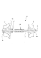
- FIG. 1 is a schematic view showing the structure of a turbocharger according to an embodiment of the present invention.
- the supercharger 1A of this embodiment includes a rotating shaft 2, a turbine wheel 3, a compressor wheel 4, a journal bearing 5A, and a thrust bearing 6A.
- the turbocharger 1A illustrated in this embodiment is mounted on a ship in such a manner that the central axis O of the rotation shaft 2 extends in the horizontal direction.
- the rotation shaft 2 is rotatably supported around a central axis O by a housing (not shown) of the turbocharger 1A.
- the turbine wheel 3 is provided on the first end 2 a side of the rotation shaft 2.
- the turbine wheel 3 rotates integrally with the rotation shaft 2 around the central axis O by the exhaust gas flow discharged from the main engine or the like of the ship.
- the compressor wheel 4 is provided on the second end 2 b side of the rotating shaft 2.
- the compressor wheel 4 rotates around the central axis O integrally with the rotating shaft 2.
- the compressor wheel 4 compresses air introduced from the outside and supplies the compressed air to a master machine or the like.
- the journal bearing 5A is supported by a bearing housing 10 (see FIG. 2) provided in a housing (not shown) of the turbocharger 1A.
- the journal bearing 5A rotatably supports the rotation shaft 2 around the central axis O.
- the journal bearing 5A mainly supports a load in the radial direction orthogonal to the central axis O of the rotating shaft 2.
- the thrust bearing 6A is provided in a housing (not shown) of the turbocharger 1A.
- the thrust bearing 6A supports a load in the direction of the central axis O of the rotary shaft 2.
- the thrust bearing 6A includes a thrust disk 7 provided on the rotating shaft 2 and a stationary disk 8 supported by a housing (not shown).
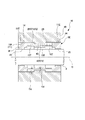
- FIG. 2 is a cross-sectional view of the journal bearing in the first embodiment of the present invention.
- the inner peripheral surface and the outer peripheral surface in the cross section perpendicular to the axis O are respectively formed in a circular shape and continuous in the central axis O direction.
- the journal bearing 5A includes a bearing portion 11A, an intermediate facing portion 12A, and a connection portion 13.
- the bearing portions 11A are respectively provided at both ends in the central axis O direction in the journal bearing 5A.
- Each bearing portion 11A includes an outer peripheral load support surface (load support surface) 14 and an inner peripheral load support surface (load support surface) 15.
- the outer peripheral load support surface 14 faces the inner peripheral surface 10 f of the bearing housing 10 in a radial direction (hereinafter simply referred to as “radial direction”) centered on the central axis O. Between the outer peripheral load supporting surface 14 and the inner peripheral surface 10 f of the bearing housing 10, a minute gap of about several ⁇ m to several tens of ⁇ m is formed. The outer peripheral load support surface 14 supports a radial load perpendicular to the central axis O between the journal bearing 5A and the bearing housing 10.
- the inner peripheral load support surface 15 radially faces the outer peripheral surface 2 f of the rotary shaft 2. Between the inner peripheral load supporting surface 15 and the outer peripheral surface 2f of the rotary shaft 2, a minute gap of about several ⁇ m to several tens of ⁇ m is formed. The inner peripheral load support surface 15 supports a radial load between the journal bearing 5A and the rotating shaft 2.
- the middle facing portion 12A is disposed between the two bearing portions 11A at both ends in the central axis O direction, and is spaced from the bearing portions 11A in the central axis O direction.
- the outer circumferential facing surface (second facing surface) 16 of the middle facing portion 12A faces the inner circumferential surface 10f of the bearing housing 10 with a gap in the radial direction.
- a radial gap (hereinafter referred to as a second gap 102) between the outer circumferential facing surface 16 of the middle facing portion 12A and the inner circumferential surface 10f of the bearing housing 10 has a dimension Cd that allows the oil film of the lubricating oil to be retained. It is set.
- the outer circumferential facing surface 16 of the middle facing portion 12A and the inner circumferential surface 10f of the bearing housing 10 constitute a second gap forming portion F2 of the present invention.
- the dimension Cd of the gap between the outer circumferential facing surface 16 of the middle facing portion 12A and the inner circumferential surface 10f of the bearing housing 10 is equal to the dimension Ca of the gap between the outer circumferential load supporting surface 14 and the inner circumferential surface 10f of the bearing housing 10, or It can be bigger than that.
- the diameter of the journal bearing 5A is D
- Cd / D 1/1000 to 20/1000 It can be done.
- the inner circumferential surface 17 of the middle opposing portion 12A in this embodiment is formed between the outer circumferential surface 2f of the rotary shaft 2 at a sufficient distance in the radial direction.
- the connecting portion 13 has a cylindrical shape extending in the central axis O direction, and connects each of the bearing portions 11A on both sides in the central axis O direction with the middle opposing portion 12A at the middle portion in the central axis O direction.
- the diameter of the outer peripheral surface (first opposing surface) 18 of the connection portion 13 is set sufficiently smaller than the inner diameter of the inner peripheral surface 10 f of the bearing housing 10.
- the outer peripheral surface 18 of the connection portion 13 is formed between the inner peripheral surface 10 f of the bearing housing 10 with a sufficient gap (hereinafter, referred to as a first gap 101) in the radial direction.
- the outer circumferential surface 18 of the connecting portion 13 and the inner circumferential surface 10 f of the bearing housing 10 constitute a first gap forming portion F1 of the present invention.
- the diameter of the inner peripheral surface (first opposing surface) 19 of the connection portion 13 is set sufficiently larger than the outer diameter of the outer peripheral surface 2 f of the rotary shaft 2.
- the inner circumferential surface 19 of the connection portion 13 is formed between the outer circumferential surface 2 f of the rotary shaft 2 at a sufficient distance in the radial direction.
- Such a journal bearing 5A has recesses 21 respectively formed by the outer peripheral surface 18 of the connecting portion 13 between the outer peripheral load support surfaces 14 adjacent to each other with a gap in the central axis O direction.
- the recess 21 is formed so as to be recessed inward in the radial direction with respect to the outer peripheral surface (for example, the outer peripheral load supporting surface 14 and the outer peripheral facing surface 16) of the journal bearing 5A.
- the journal bearing 5A further has a convex portion 22 forming an outer peripheral facing surface 16 of the middle facing portion 12A in the middle of the two concave portions 21 in the central axis O direction.
- the convex portion 22 protrudes outward in the radial direction with respect to the outer peripheral surface 18 of the concave portion 21.
- an oil film of lubricating oil is formed in the gap between the inner peripheral load supporting surface 15 of the bearing portion 11A located at both ends in the central axis O direction and the outer peripheral surface 2f of the rotary shaft 2.
- the oil film is formed as the lubricating oil is drawn into the gap between the inner peripheral load supporting surface 15 and the outer peripheral surface 2 f of the rotary shaft 2 as the rotary shaft 2 rotates.
- the oil film is reliably formed, the frictional resistance between the inner peripheral load supporting surface 15 and the outer peripheral surface 2 f of the rotary shaft 2 is reduced, and the vibration damping effect in the radial direction of the rotary shaft 2 is exerted.
- journal bearing 5A an oil film of lubricating oil is formed in the gap between the outer peripheral load supporting surface 14 of the bearing portion 11A located at both ends in the central axis O direction and the inner peripheral surface 10f of the bearing housing 10.
- the oil film exerts a vibration damping effect in the radial direction between the journal bearing 5A and the bearing housing 10.
- journal bearing 5A has an oil film of lubricating oil in the second gap 102 between the outer circumferential facing surface 16 of the middle facing portion 12A located at the middle in the central axis O direction and the inner circumferential surface 10f of the bearing housing 10. Is formed.
- the oil film exerts a vibration damping effect in the radial direction between the journal bearing 5A and the bearing housing 10.
- the bearing portions 11A (the outer peripheral load support surface 14 and the inner peripheral load support surface 15) at two places spaced in the central axis O direction. Equipped with As described above, since the two bearing portions 11A separated in the central axis O direction are integrated, the behavior of the two bearing portions 11A is suppressed. Thereby, the vibration of the conical mode of the rotating shaft 2 can be suppressed. Further, a first gap 101 and a second gap 102 are formed between the bearing portions 11A adjacent in the central axis O direction, and the second gap 102 is smaller than the first gap 101.
- an oil film of lubricating oil can be held between the bearing housing 10 and the outer peripheral facing surface 16 of the middle facing portion 12A of the journal bearing 5A in the second gap 102.
- the vibration damping effect of the rotation shaft 2 can be obtained by this oil film.
- journal bearing 5A integrally includes an intermediate facing portion 12A that forms the second gap 102 between the plurality of bearing portions 11A. Vibration of the conical mode and the parallel mode of the rotating shaft 2 can be suppressed by such a journal bearing 5A.
- the second gap 102 is disposed at an intermediate portion of the outer peripheral load support surface 14 adjacent in the central axis O direction.
- FIG. 3 is a cross-sectional view showing a journal bearing of a rotary machine in a second embodiment of the present invention.
- the journal bearing 5B of the turbocharger 1B in this embodiment integrally includes a bearing portion 11B, an intermediate facing portion 12B, and a connection portion 13.
- Each bearing 11B is provided at both ends in the central axis O direction in the journal bearing 5B.
- Each bearing 11 ⁇ / b> B includes an outer peripheral load support surface 14 and an inner peripheral load support surface 15.
- the middle opposing portion 12B is disposed at an intermediate portion between the two bearing portions 11B in the central axis O direction.
- the outer circumferential facing surface 16 of the middle facing portion 12B faces the inner circumferential surface 10f of the bearing housing 10 with a gap in the radial direction.
- the inner circumferential facing surface (second facing surface) 17B of the middle facing portion 12B faces the outer circumferential surface 2f of the rotary shaft 2 with a gap in the radial direction.
- a radial gap (hereinafter referred to as a second gap 104) between the inner circumferential opposing surface 17B of the middle opposing portion 12B and the outer circumferential surface 2f of the rotary shaft 2 has a dimension Cd that allows the oil film of the lubricating oil to be retained. It is set.
- Cd / D 1/1000 to 20/1000 It is preferable to
- connection portion 13 connects each of the bearing portions 11B positioned on both sides in the central axis O direction with the intermediate facing portion 12B positioned in the middle portion in the central axis O direction.
- Such a journal bearing 5B has a recess 23 forming the inner peripheral surface 19 of the connection portion 13 between two adjacent inner peripheral load support surfaces 15 spaced apart in the central axis O direction.
- the recess 23 is formed so as to be recessed radially outward with respect to the inner peripheral surface of the journal bearing 5B.
- the journal bearing 5B has a convex portion 24 that forms an inner circumferential opposing surface 17B of the intermediate opposing portion 12B at an intermediate portion between two concave portions 23 adjacent in the central axis O direction.
- the convex portion 24 protrudes radially inward with respect to the inner circumferential surface 19 forming the concave portion 23.
- the supercharger 1B is provided with a first gap 103 and a second gap 104 between the journal bearing 5B and the outer peripheral surface 2f of the rotary shaft 2.
- the first gap 103 is formed between the recess 23 (inner peripheral surface 19) and the outer peripheral surface 2f of the rotating shaft 2.
- the first gap 103 has a dimension Cg in the radial direction.
- the second gap 104 is formed between the convex portion 24 (inner peripheral facing surface 17B) and the outer peripheral surface 2f of the rotating shaft 2.
- the second gap 104 has a dimension (second dimension) Cd smaller than the dimension Cg in the radial direction.
- the inner circumferential surface 19 of the recess 23 and the outer circumferential surface 2f of the rotary shaft 2 constitute a first gap forming portion F3 of the present invention.
- the inner peripheral facing surface 17B of the convex portion 24 and the outer peripheral surface 2f of the rotary shaft 2 constitute a second gap forming portion F4 of the present invention.
- journal bearing 5B is located between the inner peripheral load supporting surface 15 of the bearing portion 11B at both ends in the central axis O direction and the outer peripheral surface 2f of the rotating shaft 2
- An oil film is formed by the lubricating oil.
- the oil film is reliably formed, the frictional resistance between the inner peripheral load supporting surface 15 and the outer peripheral surface 2 f of the rotary shaft 2 is reduced, and the vibration damping effect in the radial direction of the rotary shaft 2 is exerted.
- journal bearing 5B an oil film of lubricating oil is formed between the outer peripheral load supporting surface 14 of the bearing portion 11B at both ends in the central axis O direction and the inner peripheral surface 10f of the bearing housing 10.
- the oil film exhibits a vibration damping effect in the radial direction between the journal bearing 5 B and the bearing housing 10.
- an oil film of lubricating oil is formed between the outer circumferential facing surface 16 of the middle facing portion 12B at the middle portion in the central axis O direction and the inner circumferential surface 10f of the bearing housing 10.
- the oil film exhibits a vibration damping effect in the radial direction between the journal bearing 5 B and the bearing housing 10.
- journal bearing 5B an oil film of lubricating oil is formed between the inner peripheral opposing surface 17B of the middle opposing portion 12B at the intermediate portion in the central axis O direction and the outer peripheral surface 2f of the rotary shaft 2.
- the oil film exhibits a vibration damping effect in the radial direction between the journal bearing 5B and the rotary shaft 2.
- the bearing portions 11B (the outer peripheral load support surface 14 and the inner peripheral load support surface 15) at two places spaced in the central axis O direction. Is provided.
- the two bearing portions 11B spaced in the central axis O direction are integrated, it is possible to suppress the two bearing portions 11B from individually acting. Thereby, the vibration of the conical mode of the rotating shaft 2 can be suppressed.
- the first gap 103 and the second gap 104 are formed between the bearing portions 11B adjacent in the central axis O direction, and the second gap 104 is the first Smaller than the gap 103 of Thereby, in the second gap 104, the oil film of the lubricating oil can be held between the rotary shaft 2 and the inner peripheral facing surface 17B of the intermediate facing portion 12B of the journal bearing 5B.
- the vibration damping effect of the rotation shaft 2 can be obtained by this oil film.
- the vibration of the parallel mode of the rotating shaft 2 can be suppressed by providing the second gap 104 for exhibiting the vibration damping effect between the inner peripheral load supporting surfaces 15 of the plurality of bearing portions 11B. .
- the first gap 101 and the second gap 102 are formed between the bearing portions 11B adjacent in the central axis O direction, and the second The gap 102 has a dimension Cd smaller than the dimension Cg of the first gap 101 in the radial direction.
- an oil film of lubricating oil can be held between the bearing housing 10 and the outer peripheral facing surface 16 of the middle facing portion 12B of the journal bearing 5B in the second gap 102.
- the vibration damping effect of the rotation shaft 2 can be obtained by this oil film.
- the second clearances 102 and 104 that exhibit the vibration damping effect are provided between the outer peripheral load support surfaces 14 of the plurality of bearing portions 11B in the axis O direction and between the inner peripheral load support surfaces 15 respectively.
- the vibration in the parallel mode of the rotating shaft 2 can be further suppressed.
- journal bearing 5B integrally includes an intermediate facing portion 12B that forms the second gaps 102 and 104 between the plurality of bearing portions 11B. Vibration of the conical mode and the parallel mode of the rotary shaft 2 can be suppressed by such a journal bearing 5B.
- the second gap 104 is disposed at an intermediate portion of the inner peripheral load support surface 15 adjacent in the central axis O direction.
- FIG. 4 is a schematic view showing a configuration of a journal bearing in a first modified example of the second embodiment.
- the journal bearing 5 ⁇ / b> C of the first modified example integrally includes a bearing portion 11 ⁇ / b> C, an intermediate facing portion 12 ⁇ / b> C, and a connection portion 13.
- the supercharger 1C has a first gap 103 formed by the inner peripheral surface 19 of the recess 23 and an inner periphery of the protrusion 24 on the inner peripheral surface side of the journal bearing 5C as in the second embodiment described above. And a second gap 104 formed by the facing surface 17C.
- the recess 21 and the protrusion 22 are not formed on the outer peripheral surface of the journal bearing 5C.
- such a supercharger 1 ⁇ / b> C includes the first and second recesses 23 and 24 formed on the inner circumferential surface of the journal bearing 5 ⁇ / b> B and the outer circumferential surface 2 f of the rotary shaft 2. And a second gap 104.
- the oil film of the lubricating oil can be held between the outer peripheral surface 2f of the rotary shaft 2 and the inner peripheral facing surface (second facing surface) 17C of the middle facing portion 12C.
- the vibration damping effect of the rotation shaft 2 can be obtained by this oil film.
- the vibration of the parallel mode of the rotating shaft 2 can be suppressed by providing the second gap 104 that exerts the vibration damping effect between the inner peripheral load supporting surfaces 15 of the plurality of bearing portions 11C. .
- FIG. 5 is a schematic diagram which shows the structure of the rotary machine in a 2nd modification of 2nd embodiment, and a journal bearing.
- a supercharger 1D according to the second modification includes a shaft side protrusion 30 between adjacent bearing portions 11D in the direction of the central axis O in the journal bearing 5D.
- the shaft side protrusion 30 protrudes radially outward from the outer peripheral surface 2 f of the rotation shaft 2.
- the turbocharger 1D is provided with a second gap 106 between the shaft-side protrusion 30 and the recess 26 formed in the inner peripheral surface of the journal bearing 5D.
- the dimension Cd in the radial direction of the second gap 106 is smaller than the dimension Cg of the first gap 105 formed between the outer circumferential surface 2 f of the rotary shaft 2 and the recess 26.
- the inner circumferential surface 26f of the recess 26 and the outer circumferential surface 2f of the rotary shaft 2 constitute a first gap forming portion F5 of the present invention.
- the outer peripheral surface 30f of the shaft side protrusion 30 and the inner peripheral surface 26f of the recess 26 constitute a second gap forming portion F6 of the present invention.
- Such a supercharger 1D forms a second gap 106 between the shaft-side protrusion 30 and the recess 26. As described above, the supercharger 1D can suppress the vibration in the parallel mode of the rotation shaft 2 by exhibiting the vibration damping effect by the oil film formed in the second gap 106.
- FIG. 6 is a schematic view showing the configuration of a third modification of the rotary machine and the journal bearing in the second embodiment.
- a turbocharger 1E of this third modification includes a housing-side protrusion 40 between two bearing portions 11E adjacent in the central axis O direction in the journal bearing 5E.
- the housing side protrusion 40 protrudes radially inward from the inner circumferential surface 10 f of the bearing housing 10.
- the turbocharger 1E is provided with a second gap 108 between the inner circumferential surface 40f of the housing-side protrusion 40 and the outer circumferential surface 25f of the recess 25.
- the radial dimension Cd of the second gap 108 is smaller than the dimension Cg of the first gap 107 formed between the inner circumferential surface 10 f of the bearing housing 10 and the recess 25.
- Such a supercharger 1E has a second gap 108 between the housing-side protrusion 40 and the recess 25 formed on the outer peripheral surface of the journal bearing 5E. Thereby, the vibration of the parallel mode of the rotating shaft 2 can be suppressed.
- FIG. 7 is a cross-sectional view showing a journal bearing of a rotary machine in a third embodiment of the present invention.
- the supercharger 1F in the third embodiment includes the journal bearing 5A having the same configuration as that of the first embodiment.
- the supercharger 1F further includes a lubricating oil supply unit 60F.
- the lubricating oil supply portion 60F has a lubricating oil flow path 61 for supplying a lubricating oil between the middle opposing portion 12A of the journal bearing 5F and the rotary shaft 2 and the bearing housing 10.
- the lubricating oil channel 61 is provided with one or more in the circumferential direction around the central axis O.
- the lubricating oil supply unit 60F feeds lubricating oil between the middle opposing portion 12A and the rotary shaft 2 and the bearing housing 10 by a pump (not shown) or the like. In such a lubricating oil supply unit 60F, an oil film of lubricating oil is formed in the second gap 102 by the lubricating oil fed through the lubricating oil passage 61.
- the vibration damping effect of the rotary shaft 2 can be further obtained at the intermediate portion between the plurality of bearing portions 11A by the oil film formed in the second gap 102.
- an oil film can be formed by the lubricating oil fed in by the lubricating oil supply unit 60F.
- This oil film can enhance the vibration damping effect of the rotating shaft 2.
- by providing the second gap 102 that exerts the vibration damping effect by the oil film of the lubricating oil it is possible to further suppress the parallel mode vibration of the rotary shaft 2 by the oil pressure of the lubricating oil.
- the two bearing portions 11A spaced in the central axis O direction are integrated in the journal bearing 5C, it is possible to suppress the two bearing portions 11A from individually acting. . Thereby, the vibration of the conical mode of the rotating shaft 2 can be suppressed.
- FIG. 8 is a cross-sectional view showing a journal bearing of a rotary machine in a fourth embodiment of the present invention.
- the turbocharger 1 ⁇ / b> G in the fourth embodiment includes a journal bearing 5 ⁇ / b> G having the same configuration as that of the first embodiment.
- the supercharger 1G further includes a lubricating oil supply unit 60G.
- the lubricating oil supply unit 60G has a lubricating oil flow path 62 for supplying a lubricating oil between each of the bearings 11A of the journal bearing 5G and the rotary shaft 2 and the bearing housing 10.
- the lubricating oil supply unit 60G lubricates between the outer peripheral load support surface 14 of each bearing 11A and the bearing housing 10 and between the inner peripheral load support surface 15 and the rotary shaft 2 by a pump (not shown) or the like. Feed the oil.
- Such a lubricating oil supply unit 60G is provided between the outer peripheral load support surface 14 of each bearing 11A and the bearing housing 10 and with the inner peripheral load support surface 15 by the lubricating oil fed through the lubricating oil passage 62. Oil films of lubricating oil are formed between the rotary shaft 2 and the rotary shaft 2, respectively.
- lubricating oil is fed between the outer peripheral load support surface 14, the inner peripheral load support surface 15, and the rotary shaft 2 and the bearing housing 10, and the central shaft
- the vibration damping effect of the rotary shaft 2 can be more effectively obtained by the oil supply pressure of the lubricating oil at a plurality of points spaced in the O direction.
- the two bearing portions 11A separated in the central axis O direction are integrated, so that the two bearing portions 11A do not behave individually. .
- the vibration of the conical mode of the rotating shaft 2 can be suppressed.
- the vibration damping effect of the rotating shaft 2 can be obtained by the oil film formed between the rotating shaft 2 and the bearing housing 10 and the journal bearing 5G.
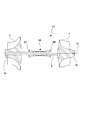
- FIG. 9 is a schematic view showing a configuration of a turbocharger according to a fifth embodiment of the present invention.
- FIG. 10 is a cross-sectional view showing a journal bearing in the fifth embodiment.
- the turbocharger 1H of the fifth embodiment includes the rotating shaft 2, the turbine wheel 3, the compressor wheel 4, the journal bearing 5A, and the thrust bearing 6H.
- the thrust bearing 6H is provided in a housing (not shown) of the turbocharger 1H.
- the thrust bearing 6H supports a load in the direction of the central axis O of the rotary shaft 2.
- the thrust bearing 6H includes a thrust disk 7H provided on the rotating shaft 2.
- the thrust disk 7H is formed to extend radially outward from the outer peripheral surface 2f of the rotating shaft 2.
- the thrust disks 7H are provided on both sides of the journal bearing 5A in the central axis O direction. Each thrust disk 7H is opposed to the end surface 5s on both sides of the journal bearing 5A in the central axis O direction.
- the journal bearing 5A is fixed to the bearing housing 10 by a fixing member 70 in order to be restrained in the central axis O direction.
- a thrust bearing 6H restricts the movement of the rotary shaft 2 in the direction of the central axis O (thrust direction) when the thrust disk 7H provided on the rotary shaft 2 abuts against the end face 5s of the journal bearing 5A.
- the thrust disk 7H is opposed to the end face 5s of the journal bearing 5A in the direction of the central axis O, respectively.
- the thrust bearing 6H is constituted by the thrust disk 7H and the journal bearing 5A. Therefore, it is possible to reduce the number of parts constituting the thrust bearing 6H.
- the space for providing the thrust bearing 6H can be reduced in the rotary shaft 2, the length in the central axis O direction of the rotary shaft 2 can be shortened. By shortening the rotation shaft 2, the natural frequency of the rotation shaft 2 can be increased, and self-excited vibration hardly occurs unless the rotation shaft 2 has a high rotation number. Also by this, the vibration of the rotating shaft 2 can be suppressed.
- FIG. 11 is a cross-sectional view of a journal bearing in another modification of the embodiment of the present invention.
- the journal bearings 5A to 5G may have a so-called multi-arc shape in which the inner peripheral surface 5h is provided with a plurality of arc-shaped surfaces 80 in the circumferential direction.
- Each arcuate surface 80 is formed to have a radius of curvature larger than the radius of curvature of the outer circumferential surface 2 f of the rotation shaft 2.
- a projection for example, the housing-side projection 40
- a protrusion opposed to the shaft-side protrusion 30 may be provided.
- journal bearings 5A to 5G integrally include the bearing portions 11A to 11F, the intermediate facing portions 12A, 12B, 12C, and 12F, and the connection portion 13. Not exclusively.
- the journal bearings 5A to 5G may be integrated by combining a plurality of parts.
- the superchargers 1A to 1H are used for ships in the embodiment described above, the present invention is not limited to this.
- the superchargers 1A to 1H may be used for vehicles such as automobiles and other applications.
- the superchargers 1A to 1H have been exemplified as the rotary machine in the above embodiment, for example, a compressor or the like may be used if it is a rotary machine.
- the present invention is applicable to rotary machines and journal bearings. According to the present invention, the vibration of the rotating shaft can be suppressed.
Landscapes
- Engineering & Computer Science (AREA)
- General Engineering & Computer Science (AREA)
- Mechanical Engineering (AREA)
- Chemical & Material Sciences (AREA)
- Combustion & Propulsion (AREA)
- Chemical Kinetics & Catalysis (AREA)
- General Chemical & Material Sciences (AREA)
- Sliding-Contact Bearings (AREA)
- Supercharger (AREA)
- Structures Of Non-Positive Displacement Pumps (AREA)
- Support Of The Bearing (AREA)
Abstract
La présente invention concerne un compresseur de suralimentation (1A) comprenant un arbre rotatif (2), un palier lisse radial (5A) et un logement de palier (10). Le palier lisse radial (5A) comprend des surfaces de support de charge (14, 15), une unité de formation de premier espace (F1) et une unité de formation de second espace (F2). L'unité de formation de premier espace (F1) forme un premier espace (101) dans la direction radiale entre des surfaces de support de charge (14, 15) qui sont adjacentes dans une direction d'axe central (O). L'unité de formation de second espace (F2) forme un second espace (102) qui est plus petit que le premier espace dans la direction radiale, entre les surfaces de support de charge (14, 15) qui sont adjacentes dans la direction d'axe central (O).
Priority Applications (4)
| Application Number | Priority Date | Filing Date | Title |
|---|---|---|---|
| EP18875550.8A EP3708857B1 (fr) | 2017-11-10 | 2018-07-23 | Machine rotative et palier lisse radial |
| US16/755,724 US11371388B2 (en) | 2017-11-10 | 2018-07-23 | Rotary machine and journal bearing |
| KR1020207012554A KR102316120B1 (ko) | 2017-11-10 | 2018-07-23 | 회전 기계, 저널 베어링 |
| CN201880072022.5A CN111316008B (zh) | 2017-11-10 | 2018-07-23 | 旋转机械、轴颈轴承 |
Applications Claiming Priority (2)
| Application Number | Priority Date | Filing Date | Title |
|---|---|---|---|
| JP2017217658A JP6528288B1 (ja) | 2017-11-10 | 2017-11-10 | 回転機械、ジャーナル軸受 |
| JP2017-217658 | 2017-11-10 |
Publications (1)
| Publication Number | Publication Date |
|---|---|
| WO2019092928A1 true WO2019092928A1 (fr) | 2019-05-16 |
Family
ID=66438824
Family Applications (1)
| Application Number | Title | Priority Date | Filing Date |
|---|---|---|---|
| PCT/JP2018/027480 Ceased WO2019092928A1 (fr) | 2017-11-10 | 2018-07-23 | Machine rotative et palier lisse radial |
Country Status (6)
| Country | Link |
|---|---|
| US (1) | US11371388B2 (fr) |
| EP (1) | EP3708857B1 (fr) |
| JP (1) | JP6528288B1 (fr) |
| KR (1) | KR102316120B1 (fr) |
| CN (1) | CN111316008B (fr) |
| WO (1) | WO2019092928A1 (fr) |
Cited By (1)
| Publication number | Priority date | Publication date | Assignee | Title |
|---|---|---|---|---|
| WO2021249600A1 (fr) * | 2020-06-08 | 2021-12-16 | Component 2.0 A/S | Agencement d'amortissement pour arbre tournant |
Citations (6)
| Publication number | Priority date | Publication date | Assignee | Title |
|---|---|---|---|---|
| JPS6186535U (fr) * | 1984-11-13 | 1986-06-06 | ||
| JP2008286050A (ja) * | 2007-05-16 | 2008-11-27 | Toyota Industries Corp | ターボチャージャ |
| WO2009013453A1 (fr) | 2007-07-21 | 2009-01-29 | Cummins Turbo Technologies Limited | Compresseur de suralimentation avec dispositif de suppression de vibrations |
| JP2010223249A (ja) * | 2009-03-19 | 2010-10-07 | Toyota Motor Corp | 浮動式すべり軸受装置及びこれを備える内燃機関のターボチャージャ |
| JP2015209837A (ja) * | 2014-04-30 | 2015-11-24 | 株式会社Ihi | 過給機、および、過給機給油システム |
| JP2017217658A (ja) | 2016-06-06 | 2017-12-14 | 株式会社豊田中央研究所 | レーザ加工装置、レーザ加工方法、光学系、及び肉盛り加工品 |
Family Cites Families (15)
| Publication number | Priority date | Publication date | Assignee | Title |
|---|---|---|---|---|
| US6017184A (en) * | 1997-08-06 | 2000-01-25 | Allied Signal Inc. | Turbocharger integrated bearing system |
| EP2392833A1 (fr) * | 2003-06-11 | 2011-12-07 | Mitsubishi Denki Kabushiki Kaisha | Structure d'arbre pour aubes à calage variable |
| US20070110351A1 (en) * | 2005-11-16 | 2007-05-17 | Honeywell International, Inc. | Centering mechanisms for turbocharger bearings |
| US8118570B2 (en) * | 2007-10-31 | 2012-02-21 | Honeywell International Inc. | Anisotropic bearing supports for turbochargers |
| US9140185B2 (en) * | 2009-11-24 | 2015-09-22 | Honeywell International Inc. | Locating mechanism for turbocharger bearing |
| US8534989B2 (en) * | 2010-01-19 | 2013-09-17 | Honeywell International Inc. | Multi-piece turbocharger bearing |
| US9581044B2 (en) * | 2010-10-28 | 2017-02-28 | Borgwarner Inc. | Rolling element bearing cartridge with axial thrust damping and anti-rotation assemblies |
| JP2012193709A (ja) * | 2011-03-17 | 2012-10-11 | Toyota Industries Corp | ターボチャージャの軸受構造 |
| FR2980536B1 (fr) * | 2011-09-23 | 2015-12-11 | Peugeot Citroen Automobiles Sa | Methode de mise en œuvre d'un turbocompresseur d'un vehicule automobile |
| US9121304B2 (en) * | 2012-09-11 | 2015-09-01 | Honeywell International Inc. | Outer race locating washer |
| JP6248479B2 (ja) | 2013-08-30 | 2017-12-20 | 株式会社Ihi | ロータ軸支持構造及び過給機 |
| CN104420899B (zh) * | 2013-08-30 | 2016-06-15 | 株式会社Ihi | 转子轴支承结构以及增压器 |
| JP6120003B2 (ja) * | 2014-02-26 | 2017-04-26 | トヨタ自動車株式会社 | ターボチャージャの軸受構造 |
| CN107735554A (zh) | 2015-07-21 | 2018-02-23 | 株式会社Ihi | 轴承构造以及增压器 |
| US10316742B2 (en) * | 2016-05-13 | 2019-06-11 | Garrett Transportation I Inc. | Turbocharger assembly |
-
2017
- 2017-11-10 JP JP2017217658A patent/JP6528288B1/ja active Active
-
2018
- 2018-07-23 KR KR1020207012554A patent/KR102316120B1/ko active Active
- 2018-07-23 US US16/755,724 patent/US11371388B2/en active Active
- 2018-07-23 EP EP18875550.8A patent/EP3708857B1/fr active Active
- 2018-07-23 CN CN201880072022.5A patent/CN111316008B/zh active Active
- 2018-07-23 WO PCT/JP2018/027480 patent/WO2019092928A1/fr not_active Ceased
Patent Citations (6)
| Publication number | Priority date | Publication date | Assignee | Title |
|---|---|---|---|---|
| JPS6186535U (fr) * | 1984-11-13 | 1986-06-06 | ||
| JP2008286050A (ja) * | 2007-05-16 | 2008-11-27 | Toyota Industries Corp | ターボチャージャ |
| WO2009013453A1 (fr) | 2007-07-21 | 2009-01-29 | Cummins Turbo Technologies Limited | Compresseur de suralimentation avec dispositif de suppression de vibrations |
| JP2010223249A (ja) * | 2009-03-19 | 2010-10-07 | Toyota Motor Corp | 浮動式すべり軸受装置及びこれを備える内燃機関のターボチャージャ |
| JP2015209837A (ja) * | 2014-04-30 | 2015-11-24 | 株式会社Ihi | 過給機、および、過給機給油システム |
| JP2017217658A (ja) | 2016-06-06 | 2017-12-14 | 株式会社豊田中央研究所 | レーザ加工装置、レーザ加工方法、光学系、及び肉盛り加工品 |
Non-Patent Citations (1)
| Title |
|---|
| See also references of EP3708857A4 |
Cited By (2)
| Publication number | Priority date | Publication date | Assignee | Title |
|---|---|---|---|---|
| WO2021249600A1 (fr) * | 2020-06-08 | 2021-12-16 | Component 2.0 A/S | Agencement d'amortissement pour arbre tournant |
| US11846338B2 (en) | 2020-06-08 | 2023-12-19 | Component 2.0 A/S | Damping arrangement for rotating shaft |
Also Published As
| Publication number | Publication date |
|---|---|
| US11371388B2 (en) | 2022-06-28 |
| KR102316120B1 (ko) | 2021-10-25 |
| EP3708857A1 (fr) | 2020-09-16 |
| KR20200057771A (ko) | 2020-05-26 |
| EP3708857A4 (fr) | 2021-01-13 |
| CN111316008A (zh) | 2020-06-19 |
| JP6528288B1 (ja) | 2019-06-12 |
| JP2019090434A (ja) | 2019-06-13 |
| CN111316008B (zh) | 2021-11-19 |
| US20210199021A1 (en) | 2021-07-01 |
| EP3708857B1 (fr) | 2022-08-31 |
Similar Documents
| Publication | Publication Date | Title |
|---|---|---|
| CN100485206C (zh) | 径向箔片轴承 | |
| CN101069023B (zh) | 多厚度膜层轴承筒和外壳 | |
| EP2693017B1 (fr) | Turbocompresseur et procédé de fabrication d'un coussinet flottant | |
| US9599149B2 (en) | Fluid film hydrodynamic tilting pad semi-floating ring journal bearing with compliant dampers | |
| JP5071150B2 (ja) | ターボチャージャ用軸受装置 | |
| US20120237149A1 (en) | Bearing structure of turbocharger | |
| SG183771A1 (en) | Hydrodynamic axial bearing | |
| US4838711A (en) | Bearing for an exhaust-gas turbocharger | |
| JP6922928B2 (ja) | 転がり軸受用保持器、及び転がり軸受 | |
| US20160333927A1 (en) | Brush Damper Rings for Radial Fluid Bearing | |
| JP2011153668A (ja) | 軸受装置 | |
| JP6528288B1 (ja) | 回転機械、ジャーナル軸受 | |
| JP7243640B2 (ja) | 玉軸受及び軸受ユニット | |
| JP2020041636A (ja) | ダンパ軸受及びダンパ | |
| JP2010133530A (ja) | 軸受構造及び該軸受構造を備えた過給機 | |
| JPH11101128A (ja) | 過給機、その組立方法ならびに過給機に用いる軸受ユニット | |
| JP6979332B2 (ja) | ティルティングパッド軸受 | |
| CN114688166B (zh) | 动压轴承及空调机组 | |
| KR100749828B1 (ko) | 씰기능을 포함하는 래디알 포일 베어링 | |
| WO2012057012A1 (fr) | Procédé de portée pour un arbre rotatif et dispositif correspondant | |
| JP2006077871A (ja) | 軸受構造 | |
| WO2018029837A1 (fr) | Palier lisse radial et machine rotative | |
| WO2020174611A1 (fr) | Palier à coussinet flottant et compresseur de suralimentation | |
| JP2018025183A (ja) | ターボチャージャー用転がり軸受および回り止め機構 | |
| JP2008095723A (ja) | 転がり軸受 |
Legal Events
| Date | Code | Title | Description |
|---|---|---|---|
| 121 | Ep: the epo has been informed by wipo that ep was designated in this application |
Ref document number: 18875550 Country of ref document: EP Kind code of ref document: A1 |
|
| ENP | Entry into the national phase |
Ref document number: 20207012554 Country of ref document: KR Kind code of ref document: A |
|
| NENP | Non-entry into the national phase |
Ref country code: DE |
|
| ENP | Entry into the national phase |
Ref document number: 2018875550 Country of ref document: EP Effective date: 20200610 |