WO2019093166A1 - 可変容量型圧縮機用制御弁 - Google Patents
可変容量型圧縮機用制御弁 Download PDFInfo
- Publication number
- WO2019093166A1 WO2019093166A1 PCT/JP2018/040040 JP2018040040W WO2019093166A1 WO 2019093166 A1 WO2019093166 A1 WO 2019093166A1 JP 2018040040 W JP2018040040 W JP 2018040040W WO 2019093166 A1 WO2019093166 A1 WO 2019093166A1
- Authority
- WO
- WIPO (PCT)
- Prior art keywords
- valve body
- valve
- main valve
- chamber
- main
- Prior art date
- Legal status (The legal status is an assumption and is not a legal conclusion. Google has not performed a legal analysis and makes no representation as to the accuracy of the status listed.)
- Ceased
Links
Images


Classifications
-
- F—MECHANICAL ENGINEERING; LIGHTING; HEATING; WEAPONS; BLASTING
- F04—POSITIVE - DISPLACEMENT MACHINES FOR LIQUIDS; PUMPS FOR LIQUIDS OR ELASTIC FLUIDS
- F04B—POSITIVE-DISPLACEMENT MACHINES FOR LIQUIDS; PUMPS
- F04B27/00—Multi-cylinder pumps specially adapted for elastic fluids and characterised by number or arrangement of cylinders
- F04B27/08—Multi-cylinder pumps specially adapted for elastic fluids and characterised by number or arrangement of cylinders having cylinders coaxial with, or parallel or inclined to, main shaft axis
- F04B27/14—Control
- F04B27/16—Control of pumps with stationary cylinders
- F04B27/18—Control of pumps with stationary cylinders by varying the relative positions of a swash plate and a cylinder block
-
- F—MECHANICAL ENGINEERING; LIGHTING; HEATING; WEAPONS; BLASTING
- F04—POSITIVE - DISPLACEMENT MACHINES FOR LIQUIDS; PUMPS FOR LIQUIDS OR ELASTIC FLUIDS
- F04B—POSITIVE-DISPLACEMENT MACHINES FOR LIQUIDS; PUMPS
- F04B27/00—Multi-cylinder pumps specially adapted for elastic fluids and characterised by number or arrangement of cylinders
- F04B27/08—Multi-cylinder pumps specially adapted for elastic fluids and characterised by number or arrangement of cylinders having cylinders coaxial with, or parallel or inclined to, main shaft axis
- F04B27/0804—Multi-cylinder pumps specially adapted for elastic fluids and characterised by number or arrangement of cylinders having cylinders coaxial with, or parallel or inclined to, main shaft axis having rotary cylinder block
- F04B27/0821—Multi-cylinder pumps specially adapted for elastic fluids and characterised by number or arrangement of cylinders having cylinders coaxial with, or parallel or inclined to, main shaft axis having rotary cylinder block component parts, details, e.g. valves, sealings, lubrication
- F04B27/0839—Multi-cylinder pumps specially adapted for elastic fluids and characterised by number or arrangement of cylinders having cylinders coaxial with, or parallel or inclined to, main shaft axis having rotary cylinder block component parts, details, e.g. valves, sealings, lubrication valve means, e.g. valve plate
-
- F—MECHANICAL ENGINEERING; LIGHTING; HEATING; WEAPONS; BLASTING
- F04—POSITIVE - DISPLACEMENT MACHINES FOR LIQUIDS; PUMPS FOR LIQUIDS OR ELASTIC FLUIDS
- F04B—POSITIVE-DISPLACEMENT MACHINES FOR LIQUIDS; PUMPS
- F04B27/00—Multi-cylinder pumps specially adapted for elastic fluids and characterised by number or arrangement of cylinders
- F04B27/08—Multi-cylinder pumps specially adapted for elastic fluids and characterised by number or arrangement of cylinders having cylinders coaxial with, or parallel or inclined to, main shaft axis
- F04B27/10—Multi-cylinder pumps specially adapted for elastic fluids and characterised by number or arrangement of cylinders having cylinders coaxial with, or parallel or inclined to, main shaft axis having stationary cylinders
- F04B27/1009—Distribution members
-
- F—MECHANICAL ENGINEERING; LIGHTING; HEATING; WEAPONS; BLASTING
- F04—POSITIVE - DISPLACEMENT MACHINES FOR LIQUIDS; PUMPS FOR LIQUIDS OR ELASTIC FLUIDS
- F04B—POSITIVE-DISPLACEMENT MACHINES FOR LIQUIDS; PUMPS
- F04B27/00—Multi-cylinder pumps specially adapted for elastic fluids and characterised by number or arrangement of cylinders
- F04B27/08—Multi-cylinder pumps specially adapted for elastic fluids and characterised by number or arrangement of cylinders having cylinders coaxial with, or parallel or inclined to, main shaft axis
- F04B27/14—Control
- F04B27/16—Control of pumps with stationary cylinders
- F04B27/18—Control of pumps with stationary cylinders by varying the relative positions of a swash plate and a cylinder block
- F04B27/1804—Controlled by crankcase pressure
-
- F—MECHANICAL ENGINEERING; LIGHTING; HEATING; WEAPONS; BLASTING
- F04—POSITIVE - DISPLACEMENT MACHINES FOR LIQUIDS; PUMPS FOR LIQUIDS OR ELASTIC FLUIDS
- F04B—POSITIVE-DISPLACEMENT MACHINES FOR LIQUIDS; PUMPS
- F04B53/00—Component parts, details or accessories not provided for in, or of interest apart from, groups F04B1/00 - F04B23/00 or F04B39/00 - F04B47/00
- F04B53/10—Valves; Arrangement of valves
- F04B53/108—Valves characterised by the material
- F04B53/1082—Valves characterised by the material magnetic
-
- F—MECHANICAL ENGINEERING; LIGHTING; HEATING; WEAPONS; BLASTING
- F16—ENGINEERING ELEMENTS AND UNITS; GENERAL MEASURES FOR PRODUCING AND MAINTAINING EFFECTIVE FUNCTIONING OF MACHINES OR INSTALLATIONS; THERMAL INSULATION IN GENERAL
- F16K—VALVES; TAPS; COCKS; ACTUATING-FLOATS; DEVICES FOR VENTING OR AERATING
- F16K31/00—Actuating devices; Operating means; Releasing devices
- F16K31/02—Actuating devices; Operating means; Releasing devices electric; magnetic
- F16K31/06—Actuating devices; Operating means; Releasing devices electric; magnetic using a magnet, e.g. diaphragm valves, cutting off by means of a liquid
- F16K31/0644—One-way valve
- F16K31/0655—Lift valves
-
- F—MECHANICAL ENGINEERING; LIGHTING; HEATING; WEAPONS; BLASTING
- F04—POSITIVE - DISPLACEMENT MACHINES FOR LIQUIDS; PUMPS FOR LIQUIDS OR ELASTIC FLUIDS
- F04B—POSITIVE-DISPLACEMENT MACHINES FOR LIQUIDS; PUMPS
- F04B27/00—Multi-cylinder pumps specially adapted for elastic fluids and characterised by number or arrangement of cylinders
- F04B27/08—Multi-cylinder pumps specially adapted for elastic fluids and characterised by number or arrangement of cylinders having cylinders coaxial with, or parallel or inclined to, main shaft axis
- F04B27/14—Control
- F04B27/16—Control of pumps with stationary cylinders
- F04B27/18—Control of pumps with stationary cylinders by varying the relative positions of a swash plate and a cylinder block
- F04B27/1804—Controlled by crankcase pressure
- F04B2027/1809—Controlled pressure
- F04B2027/1813—Crankcase pressure
-
- F—MECHANICAL ENGINEERING; LIGHTING; HEATING; WEAPONS; BLASTING
- F04—POSITIVE - DISPLACEMENT MACHINES FOR LIQUIDS; PUMPS FOR LIQUIDS OR ELASTIC FLUIDS
- F04B—POSITIVE-DISPLACEMENT MACHINES FOR LIQUIDS; PUMPS
- F04B27/00—Multi-cylinder pumps specially adapted for elastic fluids and characterised by number or arrangement of cylinders
- F04B27/08—Multi-cylinder pumps specially adapted for elastic fluids and characterised by number or arrangement of cylinders having cylinders coaxial with, or parallel or inclined to, main shaft axis
- F04B27/14—Control
- F04B27/16—Control of pumps with stationary cylinders
- F04B27/18—Control of pumps with stationary cylinders by varying the relative positions of a swash plate and a cylinder block
- F04B27/1804—Controlled by crankcase pressure
- F04B2027/1822—Valve-controlled fluid connection
- F04B2027/1827—Valve-controlled fluid connection between crankcase and discharge chamber
Definitions
- the present invention relates to a control valve for a variable displacement compressor used in a car air conditioner or the like, and in particular, to a valve body caused by foreign matter flowing into a sliding surface gap formed between the valve body and a guide hole.
- the present invention relates to a control valve for a variable displacement compressor that is less likely to cause a malfunction.
- a discharge pressure Pd is introduced from a discharge chamber of the compressor, and the discharge pressure Pd is adjusted in accordance with a suction pressure Ps of the compressor.
- An electromagnetic actuator having a valve body, a main valve body (valve rod) for opening and closing the valve port, and a plunger for moving the main valve body in the valve port opening and closing direction, suction pressure Ps from the compressor Is through the Ps entrance and exit And includes a sensing chamber to be introduced, and sensitive ⁇ rotary members of the bellows arrangement such that urges the main valve body the valve port opening and closing directions in response to pressure sensitive chamber, a Te.
- the control valve for a variable displacement compressor described in Patent Document 2 and the like described below releases the pressure Pc of the crank chamber to the suction chamber of the compressor via the Ps inlet and outlet.
- an auxiliary valve body for opening and closing the in-valve escape passage, and the plunger is continuously moved upward from the lowest position by the suction force of the electromagnetic actuator.
- the main valve is moved upward so as to follow the auxiliary valve while the auxiliary valve moves upward with the release passage closed in the valve together with the plunger, and the main valve After the valve port is closed by the body, when the plunger is further moved upward, the sub valve body opens the relief passage in the valve.
- the main valve body which opens and closes a valve port is slidably inserted in the guide hole provided in the valve main body.
- Foreign material cutting and polishing debris left after processing and assembly
- the sliding surface clearance formed between (the outer peripheral surface of the main valve body and (the inner wall surface of) the guide hole.
- the seal member is usually interposed between the main valve body and the guide hole as shown in Patent Document 3 below. It is considered to interpose an O-ring.
- JP, 2010-185285 A JP, 2013-130126, A JP, 2011-043102, A
- the present invention has been made in view of the above circumstances, and an object of the present invention is to prevent foreign matter from invading the sliding surface clearance (clearance) formed between the main valve body and the guide hole. Another object of the present invention is to provide a control valve for a variable displacement compressor that can effectively suppress an increase in sliding resistance and a decrease in control characteristics associated therewith. Another object of the present invention is to provide a control valve for a variable displacement compressor that can ensure stable sealing performance regardless of dimensional error of components.
- a control valve for a variable displacement compressor basically includes a main valve body having a main valve body portion, and a guide hole in which the main valve body is slidably inserted.
- a valve chamber provided with a valve port for contacting and separating the main valve body portion; and a Ps inlet / outlet communicating with a suction chamber of the compressor, and communicating with a discharge chamber of the compressor upstream from the valve port
- a valve body provided with a Pd inlet and provided with a Pc inlet / outlet communicating with the crank chamber of the compressor downstream of the valve port, and an electromagnetic force for moving the main valve body in the valve port opening / closing direction Actuator, pressure sensing chamber where suction pressure Ps is introduced from the compressor via the Ps inlet / outlet, and sense that the main valve body is urged in the opening / closing direction according to the pressure of the pressure sensing chamber
- a gap is provided between a portion on the valve chamber side of the plate-like ring member in the guide hole and the main valve body.
- the plate-like ring member has the tubular portion formed at its inner end, and the tubular portion is brought into sliding contact with the outer wall of the main valve body, so that the guide hole is formed. It is fixed by holding.
- the plate-like ring member is sandwiched between two members constituting the guide hole of the valve body.
- the two members are fixed to one another by means of a press fit.
- At least one of the two members is provided with a stopper portion for restricting the movement of the plunger of the electromagnetic actuator.
- the plate-like ring member is held and fixed to the guide hole or the main valve body via an O-ring.
- the O-ring is disposed on the opposite side to the valve chamber side of the plate-like ring member.
- the plate-like ring member has the cylindrical portion formed at the outer end thereof, and the cylindrical portion is brought into sliding contact with the inner wall of the guide hole, thereby the main valve body It is fixed by holding.
- an in-valve relief passage for evacuating the pressure Pc of the crank chamber to the suction chamber of the compressor via the Ps inlet / outlet is provided in the valve body or the main valve body, and An auxiliary valve body is provided for opening and closing the in-valve relief passage.
- the plate-like ring member mounted between the guide hole and the main valve body.
- the plate-like ring member has less frictional resistance and less deformation (deflection), so that It is possible to effectively suppress the increase and the associated decrease in control characteristics.
- the plate-like ring member is held and fixed to the guide hole of the valve body via, for example, an O-ring, the creep phenomenon of the plate-like ring member can be suppressed, which also increases the sliding resistance. And the fall of the control characteristic accompanying it can be suppressed effectively.
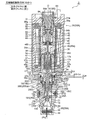
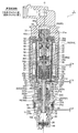
- the main valve of 1st Embodiment of the control valve for variable displacement compressors which concerns on this invention The longitudinal cross-sectional view which shows the state of opening.
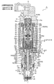
- the main valve of 1st Embodiment of the control valve for variable displacement compressors which concerns on this invention The longitudinal cross-sectional view which shows the state of closing.
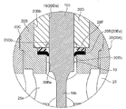
- the A section enlarged view of FIG. The A section enlarged view of FIG. BRIEF DESCRIPTION OF THE DRAWINGS
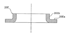
- the longitudinal cross-sectional view which shows the plate-shaped ring member (molding state) used for 1st Embodiment of the control valve for variable displacement type compressors which concerns on this invention.
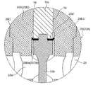
- the main valve of the other example of 1st Embodiment of the control valve for variable displacement compressors which concerns on this invention The enlarged view corresponding to the A section of FIG. 1 which shows the state of opening.
- the main valve of the other example of 1st Embodiment of the control valve for variable displacement type compressors which concerns on this invention The enlarged view corresponding to the A section of FIG. 2 which shows the state of closing.
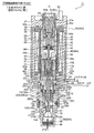
- the main valve of 2nd Embodiment of the control valve for variable displacement type compressors which concerns on this invention The longitudinal cross-sectional view which shows the state (at the time of normal control) of an open, an auxiliary valve: closed.
- the main valve of 2nd Embodiment of the control valve for variable displacement type compressors which concerns on this invention The vertical valve which shows the state (compressor start transition time (the 1)) of the closed and subvalve: closed states.
- the main valve of 2nd Embodiment of the control valve for variable displacement compressors which concerns on this invention The vertical valve which shows the state (at the time of compressor start) of the closed and subvalve open states.
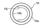
- the B section enlarged view of FIG. The perspective view which shows the subvalve body used for 2nd Embodiment of the control valve for variable displacement type compressors which concerns on this invention.
- the front view which shows the subvalve body used for 2nd Embodiment of the control valve for variable displacement type compressors which concerns on this invention.
- the left view which shows the subvalve body used for 2nd Embodiment of the control valve for variable displacement type compressors which concerns on this invention.
- the top view which shows the subvalve body used for 2nd Embodiment of the control valve for variable displacement compressors which concerns on this invention.
- the bottom view which shows the subvalve body used for 2nd Embodiment of the control valve for variable displacement type compressors which concerns on this invention.
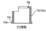
- Sectional drawing which follows the VV arrow line of FIG. 13C which shows the subvalve body used for 2nd Embodiment of the control valve for variable displacement type compressors which concerns on this invention.
- the longitudinal cross-sectional view which shows the state (at the time of normal control) of the main valve of 3rd Embodiment of the control valve for variable displacement compressors which concerns on this invention: open, subvalve: closed state.
- the main valve of 3rd Embodiment of the control valve for variable displacement type compressors which concerns on this invention The vertical valve which shows the state (at the time of compressor start shift) of the closing and subvalve closing states.
- the main valve of 3rd Embodiment of the control valve for variable displacement type compressors which concerns on this invention The vertical valve which shows the state (at the time of compressor start) of the closed and subvalve open states.
- the C section enlarged view of FIG. The principal part expansion longitudinal cross-sectional view which shows the other example of 1st Embodiment of the control valve for variable displacement type compressors which concerns on this invention.
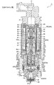
- First Embodiment 1 and 2 are longitudinal sectional views showing a first embodiment of a control valve for a variable displacement compressor according to the present invention
- FIG. 1 is a main valve: opened
- FIG. 2 is a main valve: closed
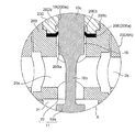
- FIG.3 and FIG.4 is the A section enlarged view of FIG.1 and FIG.2, respectively.
- the gap formed between the members, the separation distance between the members, and the like are large in comparison with the dimensions of the respective constituent members in order to facilitate understanding of the invention and for convenience in drawing. Or it may be drawn small.
- the control valve 1 of the illustrated embodiment basically includes a valve main body 20 provided with a valve port 22, a main valve body 10 for opening and closing the valve port 22, and a main valve body 10 in a valve opening / closing direction
- the electromagnetic actuator 30 for moving in the vertical direction), and the bellows device 40 as a pressure sensitive response member.
- the electromagnetic actuator 30 includes a bobbin 38, a coil 32 for energization and excitation provided outside the bobbin 38, a stator 33 and a suction element 34 disposed on the inner peripheral side of the coil 32, a lower end of the stator 33 and the suction element 34 A guide pipe 35 whose upper end is joined to the outer periphery (step portion) by welding, and a bottomed cylindrical plunger slidably disposed vertically in the inner peripheral side of the guide pipe 35 below the suction element 34.
- a cylindrical housing 60 externally fitted to the coil 32, a connector head 31 mounted on the upper side of the housing 60 via a mounting plate 39 provided on the upper part of the bobbin 38, and a lower end portion and a guide of the housing 60
- a holder 29 is disposed between the lower end of the pipe 35 and the upper end of the valve body 20 (the body member 20A of the valve body 20).
- a short cylindrical suction element 34 in which an insertion hole 34a having a diameter smaller than the inner diameter of the stator 33 is formed in the lower inner periphery of the cylindrical stator 33 (along the axis O) is integrated. It is molded.
- a portion including the coil 32, the stator 33, the suction element 34 and the like excluding the plunger 37 is referred to as a solenoid unit 30A.
- a short cylindrical stator 65 is fixed to the upper portion of the stator 33 by press-fitting or the like, and the suction of the compressor is performed between the stator 65 and the suction element 34 on the inner peripheral side of the stator 33.
- a pressure sensitive chamber 45 into which the pressure Ps is introduced is formed, and in the pressure sensitive chamber 45, a bellows 41 as a pressure sensitive reaction member, a downward convex upper stopper 42, a downward concave lower stopper 43, and a compression coil spring
- a bellows device 40 consisting of 44 is disposed. Further, on the lower side of the bellows device 40, a stepped rod-like push rod 46 as a thrust transfer member is disposed along the axis O.
- the push rod 46 has an upper small diameter portion 46 d and a lower large diameter portion 46 b, and the upper small diameter portion 46 d of the push rod 46 is inserted into and supported by the recess of the lower stopper 43. Is inserted into the insertion hole 34a of The lower large diameter portion 46b of the push rod 46 is inserted (with a slight gap) into a plunger 37 having an inner diameter substantially the same as the insertion hole 34a of the suction element 34, and provided at the lower end thereof. An upper end small diameter convex portion 10t of the main valve body 10 described later is fitted into the relatively elongated concave hole 46a.
- the above-mentioned push is performed between a step (an upward annular terraced surface) 46c formed between the upper small diameter portion 46d and the lower large diameter portion 46b of the push rod 46 and (the lower surface of) the lower stopper 43.
- the push rod 46, the main valve body 10, and the plunger 37 are lowered (in the valve opening direction) so as to be extrapolated to the upper small diameter portion 46d of the rod 46. ), And a plunger spring (opening valve spring) 47 is compressed.
- the push rod 46, the main valve body 10, and the plunger 37 move up and down together in a state where the push rod 46 and the like are urged downward by (the compression force of) the plunger spring 47, and the bellows device 40 It is held in the pressure sensing chamber 45.
- a central hole 37b smaller in diameter than the inner diameter of the plunger 37 is formed at the center (on the axis O) at the bottom of the plunger 37, and a part thereof overlaps the central hole 37b at a position slightly eccentric from the center.
- an insertion hole 37c having substantially the same diameter as the inner diameter of the plunger 37 (in other words, a diameter larger than that of the central hole 37b) is formed.
- the insertion hole 37 c is formed to a depth (vertical depth) communicating with the internal space of the plunger 37.
- the hole diameter of the insertion hole 37c is slightly larger than the hook-shaped locking portion 10k of the main valve body 10 described later, and the hole diameter of the central hole 37b is the main valve body 10
- the diameter is slightly larger than the upper small diameter portion 10d, and slightly smaller than the hook-like locking portion 10k.
- the thickness (height in the vertical direction) of the bottom of the plunger 37 is slightly larger than the height of the upper small diameter portion 10 d of the main valve body 10.
- the upper small diameter convex portion 10t of the main valve body 10 is fitted into the concave hole 46a of the push rod 46, and the upper small diameter portion 10d of the main valve body 10 is inserted into the central hole 37b of the plunger 37.
- the outer peripheral portion of the central hole 37b on the upper surface of the bottom portion of the lower portion is an inner hook-shaped locking portion 37k for locking the hook-shaped locking portion 10k of the main valve body 10.
- a D-cut surface 37 d is formed at a predetermined position on the outer periphery of the plunger 37, and a gap 36 is formed between the outer periphery of (the D-cut surface 37 d thereof) the plunger 37 and the guide pipe 35.
- a gap 36 is formed between the outer periphery of (the D-cut surface 37 d thereof) the plunger 37 and the guide pipe 35.
- one or more longitudinal grooves may be formed to form a gap 36 between the outer periphery of the plunger 37 and the guide pipe 35.
- the main valve body 10 is made of, for example, metal, and is formed of a stepped axial solid member disposed along the axis O.
- the main valve body 10 includes, in order from the bottom, a main valve body portion 10a having a relatively large diameter, a lower small diameter portion 10b, an intermediate insertion portion 10c which is long in the vertical direction, an upper small diameter portion 10d, and a hook-like locking portion 10k.
- the upper end small diameter convex part 10t inserted in the concave hole 46a of the said push rod 46 is protrudingly provided by the upper surface of the hook-shaped latching
- the upper end small diameter convex portion 10t of the main valve body 10 is internally fitted in the concave hole 46a of the push rod 46, and the hook-like locking portion 10k of the main valve body 10 is larger in diameter than the concave hole 46a ( And, the diameter is slightly smaller than that of the lower large diameter portion 46b.
- the upper small diameter portion 10d of the main valve body 10 is loosely fitted in the central hole 37b of the plunger 37, and the hook-like locking portion 10k of the main valve body 10 is larger in diameter than the central hole 37b (and the plunger 37 The diameter is smaller than the inner diameter).
- the hook-shaped locking portion 10k is hooked and retained by the inner hook-shaped locking portion 37k formed by the outer peripheral portion of the central hole 37b, whereby the plunger 37 and The main valve body 10 and the push rod 46 are raised together (in one piece).
- the portion 10d is inserted into the insertion hole 37c of the plunger 37 from below, the main valve body 10 is moved laterally with respect to the plunger 37, and the central small hole 37b provided at the center of the bottom of the plunger 37 Insert the part 10d.
- the push rod 46 may be inserted into (the inside of) the plunger 37 from above, and the upper end small diameter convex portion 10 t of the main valve body 10 may be fitted in the concave hole 46 a of the push rod 46.
- the valve main body 20 mainly has a recessed hole 20C for fitting at the upper center and a stepped cylindrical main body member 20A provided with a slightly small diameter accommodation hole 18 connected to the recessed hole 20C at the lower center. And a cylindrical sheet member 20B inserted and fixed to the recessed hole 20C by press-fitting and the like, and a cylindrical guide member 20D inserted and fixed to the sheet member 20B (upper half portion) by press-fitting and the like. It is configured.
- the sheet member 20B and the guide member 20D are made of stainless steel (SUS), high-hardness brass material (brass whose hardness is increased by reducing the content of lead, etc.), etc., and are located above the central hole 20Ba of the sheet member 20B.
- the half portion has a large diameter (large diameter hole 20Bb), and the guide member 20D is a large diameter hole 20Bb of the sheet member 20B in a state where the upper end surfaces of the sheet member 20B and the guide member 20D are substantially aligned. Is fitted to.
- the lower end portion of the sheet member 20B is brought into contact with the stepped portion (stepped portion) between the recessed hole 20C of the main body member 20A and the accommodation hole 18, and the upper end portion thereof is
- the upper end portions of the sheet member 20B and the guide member 20D define the lowermost position of the plunger 37 (the lowering of the plunger 37). It is considered as the stopper 24 for performing regulation).
- the main valve body 10 (intermediate insertion portion 10c thereof) is fitted by the central hole 20Ba of the seat member 20B (specifically, the lower half below the large diameter hole 20Bb) and the central hole 20Da of the guide member 20D.
- a guide hole 19 is formed, and a valve port 22 (valve) is opened and closed by the main valve body 10a of the main valve body 10 at the lower end of the guide hole 19 (that is, the lower end of the central hole 20Ba of the seat member 20B).
- Seat section the central hole 20Ba of the seat member 20B is slightly larger in diameter than the central hole 20Da of the guide member 20D, and (the intermediate insertion portion 10c of the main valve body 10) is the guide member It is slidably inserted into the central hole 20Da of 20D and has a slight gap with the central hole 20Ba of the seat member 20B (larger diameter portion on the valve chamber 21 side than the plate-like ring member 20E described later).
- the main valve portion 11 is constituted by the main valve body portion 10 a and the valve port 22.
- the (outer diameter of) the sheet member 20B is smaller in diameter than the plunger 37.
- a plate-like ring member (also referred to as packing) 20E made of, for example, a fluorine resin such as Teflon (registered trademark) or the like and capable of being elastically deformed and having a low frictional resistance (sliding resistance)
- the inner end of the plate-like ring member 20E is in sliding contact with the outer wall (outer periphery) of the main valve body 10 (the intermediate insertion portion 10c thereof).
- the material of the plate-like ring member 20E is not limited to the above, and may be made of metal such as SUS.
- the plate-like ring member 20E is vertically moved by the guide member 20D and the sheet member 20B which constitute the guide hole 19, as can be understood well with reference to FIGS. 1 and 2 and FIGS. And the outer wall of the main valve body 10 (intermediate insertion portion 10c of the main valve body 10) connected continuously upward (guide member 20D side) from the inner end of the flat plate portion 20Ea And a substantially cylindrical or truncated cone cylindrical portion 20Eb.
- the inner diameter of the cylindrical portion 20Eb in the plate-like ring member 20E is substantially the same diameter (or slightly smaller than the outer diameter of the (intermediate insertion portion 10c of the main valve body 10) Small diameter).
- the tubular portion 20Eb of the plate-like ring member 20E may be molded by incorporating the plate-like ring member 20E into the control valve 1, or after being incorporated. Specifically, a flat plate-like ring member 20E having a diameter of the central hole smaller than the outer diameter of the main valve body 10 is prepared, and the flat plate-like ring member 20E is used as the guide member 20D and the sheet member 20B. Thus, the main valve body 10 is inserted into the guide hole 19 while holding the pressure in the vertical direction. As a result, the vicinity of the central hole of the plate-like ring member 20E (the inner peripheral side end of the plate-like ring member 20E) is plastically deformed to be formed as a cylindrical portion 20Eb.
- the molding method it is possible to realize constant sealing performance regardless of dimensional errors of the plate-like ring member 20E and the main valve body 10.
- the plate-like ring member 20E is made of a material such as fluorine resin, which exhibits thermal flexibility compared to metal, by molding the cylindrical portion 20Eb by the main valve body 10 in a high temperature environment, It is possible to shorten the time required for plastic deformation.
- valve chamber 21 (or the Pd inlet 25 described later) and the pressure sensing chamber 45 (or the Ps described later) are formed by the plate-like ring member 20E interposed and held and fixed between the guide hole 19 and the main valve body 10.
- a seal is formed between the inlet and the outlet 27) (sliding surface gap formed between the main valve body 10 and the guide hole 19).
- an enlarged diameter portion 20Db is formed in the lower end portion of the central hole 20Da of the guide member 20D to avoid interference with the cylindrical portion 20Eb of the plate-like ring member 20E.
- the main body member 20A is made of, for example, aluminum, brass, or resin, and in a state where the sheet member 20B and the like are inserted into the recessed holes 20C of the main body member 20A, the upper outer periphery of the sheet member 20B is a compressor.
- a Ps inlet / outlet chamber 28 of suction pressure Ps is formed, and a plurality of (two in the illustrated example) Ps inlet / outlet 27 is formed on the outer peripheral side of the Ps inlet / outlet chamber 28.
- the suction pressure Ps introduced from the Ps inlet / outlet 27 into the Ps inlet / outlet chamber 28 is a gap 36 formed between the outer periphery of the plunger 37 and the guide pipe 35 (in this example, a gap formed by the D cut surface 37 d ), And is introduced into the pressure sensing chamber 45 via a gap 38 formed between the outer periphery of the push rod 46 and the suction element 34.
- the receiving hole 18 having a diameter larger than that of the guide hole 19 and the main valve body 10a for accommodating the main valve body 10a of the main valve body 10 is continuously provided. It is done.
- a valve-closing spring formed of a conical compression coil spring between a bottom outer peripheral corner of the housing hole 18 and a step (step surface) 10e provided on the lower outer periphery of the main valve body 10a of the main valve body 10.
- the main valve body 10 is biased upward by the biasing force of the valve closing spring 50.
- the inside of the accommodation hole 18 (a portion below the valve port 22 of the seat member 20B) is a valve chamber 21.
- a plurality of Pd inlets 25 communicating with the discharge chamber of the compressor are opened in the concave hole 20C, and a ring-shaped filter member 25A is disposed on the outer periphery of the Pd inlet 25 and the concave
- the lower hole of the sheet member 20B inserted into the hole 20C (in particular, a portion below the portion of the main valve body 10 into which the intermediate insertion portion 10c is inserted) communicates with the Pd inlet 25 and the central hole
- a plurality of lateral holes 25s continuous with 20Ba that is, the guide holes 19
- a lid-like member 48 functioning as a filter is fixed to the lower end portion of the main body member 20A by engagement, press-fitting or the like, and above the lid-like member 48 below the accommodation hole 18 (in other words, the main body
- the lower end side of the sheet member 20B in the member 20A is a Pc inlet / outlet chamber (inlet / outlet) 26 communicating with the crank chamber of the compressor.
- control valve 1 Next, the operation of the control valve 1 configured as described above will be outlined.
- the suction pressure Ps introduced from the compressor to the Ps inlet / outlet 27 is introduced from the Ps inlet / outlet chamber 28 to the pressure sensing chamber 45 via the gap 36 between the outer periphery of the plunger 37 and the guide pipe 35
- the device 40 (the inside is a vacuum pressure) undergoes an expansion / contraction displacement (contracts when the suction pressure Ps is high, or stretches when it is low) according to the pressure (suction pressure Ps) of the pressure sensing chamber 45.
- the pressure is transmitted to the valve body 10, whereby the valve opening degree (the separation distance between the valve port 22 and the main valve body portion 10a) is adjusted, and the pressure Pc in the crank chamber is adjusted according to the valve opening degree.
- the plate-like ring member 20E mounted between the guide hole 19 and the main valve body 10 forms the space between the main valve body 10 and the guide hole 19 Can prevent the entry of foreign matter into the sliding surface clearance (clearance), and the plate-like ring member 20E has less frictional resistance than, for example, an O-ring attached as a sealing member to a conventional control valve (slip Since the deformation (the amount of deflection) can be reduced, it is possible to effectively suppress the increase in the sliding resistance and the decrease in the control characteristics.
- the cylindrical portion 20Eb of the plate-like ring member 20E faces upward from the inner end of the flat portion 20Ea (on the side of the guide member 20D and between the main valve body 10 and the guide hole 19).
- the inside of the plate-like ring member 20E is If the end (cylindrical portion 20Eb) is curved to the high pressure side (that is, the valve chamber 21 and the Pd inlet 25 side), the fluid pressure moves the inner end of the plate ring member 20E to the opposite surface (the main valve body 10). Since it works in close contact with the outer peripheral surface), it is possible to secure a better sealability even during operation.
- FIGS. 8 to 11 are longitudinal sectional views showing a second embodiment of the control valve for a variable displacement compressor according to the present invention
- FIG. 8 shows a state of main valve: open
- sub valve: closed normal control 9 and 10 show the main valve: closed
- secondary valve: closed closed (during compressor start transition)
- FIG. 11 shows the main valve: closed
- secondary valve: open compressor started
- 12 is an enlarged view of a portion B of FIG.
- the control valve 2 of the second embodiment differs from the control valve 1 of the first embodiment described above in that the pressure Pc of the crank chamber is Ps inlet / outlet 27 to improve the startability.
- the pressure Pc of the crank chamber is Ps inlet / outlet 27 to improve the startability.
- an in-valve relief passage 16 is provided for relief.
- symbol is attached
- the control valve 2 of the illustrated embodiment basically includes a valve main body 20 provided with a valve port 22, a main valve body 10 for opening and closing the valve port 22, and a main valve body 10 in a valve opening / closing direction
- the electromagnetic actuator 30 for moving in the vertical direction), and the bellows device 40 as a pressure sensitive response member.
- the electromagnetic actuator 30 includes a bobbin 38, a coil 32 for energization and excitation provided outside the bobbin 38, a stator 33 and a suction element 34 disposed on the inner peripheral side of the coil 32, a lower end of the stator 33 and the suction element 34 A guide pipe 35 whose upper end is joined to the outer periphery (step portion) by welding, and a bottomed cylindrical plunger slidably disposed vertically in the inner peripheral side of the guide pipe 35 below the suction element 34.
- a cylindrical housing 60 externally fitted to the coil 32, a connector portion 31 attached to the upper side of the housing 60 via a mounting plate 39 provided on the upper portion of the bobbin 38, and a lower end portion and a guide of the housing 60
- a holder 29 is disposed between the lower end of the pipe 35 and the upper end of the valve body 20 (the body member 20A of the valve body 20).
- a cylindrical suction element 34 having an insertion hole 34a smaller in diameter than the inner diameter of the stator 33 is formed integrally with the lower inner periphery of the cylindrical stator 33 (along the axis O). It is done.
- a solenoid unit 30A a portion including the coil 32, the stator 33, the suction element 34 and the like excluding the plunger 37 is referred to as a solenoid unit 30A.
- the lower half of the adjusting screw 65 is fitted inside the lower half of the holding member 64 (with an O-ring 62 as a seal member interposed therebetween), and A male screw portion 65 a provided on the upper outer periphery is screwed to a female screw portion 64 a provided on the upper inner periphery of the holding member 64.
- the adjustment member 61 is inserted into a fitting insertion hole 31 a formed substantially at the center of the connector portion 31 and a central hole 39 a provided substantially at the center of the mounting plate 39, and protruded at the lower outer periphery of the holding member 64.
- the flange portion 64b and the ring-shaped pressing member 63 fitted in (the fitting groove formed in) the upper portion cooperate with each other to hold and fix the connector portion 31 and the mounting plate 39 (impossible to move up and down)
- the lower end portion (portion below the flange portion 64b) (of the holding member 64) is disposed (interpolated) on the inner peripheral side of the upper end portion of the stator 33.
- a pressure sensing chamber 45 is formed, into which the suction pressure Ps of the compressor is introduced.
- a bellows device 40 including a bellows 41, a downward convex upper stopper 42, a downward concave lower stopper 43, and a compression coil spring 44 as a pressure sensitive reaction member is disposed.
- a stepped rod-like push rod 46 as a thrust transfer member is disposed along the axis O.
- An approximate center of the push rod 46 has a large diameter (large diameter portion 46 e), and the upper end 46 f of the push rod 46 is inserted and supported in the recess of the lower stopper 43, and the insertion hole 34 a of the suction element 34
- the upper portion of the push rod 46 and the large diameter portion 46e are inserted (with a slight gap 38).
- the lower portion of the push rod 46 is inserted into the recessed hole 17b of the interior member 17 having a recessed cross section described later, and the lower end 46g thereof is inserted into the recessed fitting insertion hole 17c formed in the center of the bottom of the recessed hole 17b. It is fitted.
- an interior member 17 having a concaved cross section and having a vertically elongated concave hole 17b having substantially the same diameter as the insertion hole 34a of the suction element 34 is inserted and fixed by press fitting or the like.
- the upper end of the interior member 17 is aligned with the upper end of the plunger 37 (in other words, the upper end is positioned on the inner periphery of the upper end of the plunger 37), and the lower end has a gap with the bottom of the plunger 37
- the hook-shaped locking portion 10k of the main valve body 10 is internally fitted to the plunger 37 with a clearance to be disposed so as to be slightly movable up and down).
- a concave insertion hole 17c is formed, into which the lower end 46g of the push rod 46 is inserted.
- a plunger spring (opening valve spring) 47 formed of a cylindrical compression coil spring is compressed between the upper surface and the upper surface). The plunger 37 is urged downward (in the valve opening direction) via the interior member 17 by (the compression force of) the plunger spring 47, and the bellows device 40 in the pressure sensing chamber 45 via the push rod 46. It is held.
- a slit 37s extending linearly from the outer periphery to the center (on the axis O) is formed at the bottom of the plunger 37, and the slit 37s is formed at a portion corresponding to the slit 37s at the side of the plunger 37.
- a wider notch 37t is provided. The height (in the vertical direction) of the notch 37t is slightly larger than the height of the hook-like locking portion 10k of the main valve body 10, and the height (in the vertical direction) of the slit 37s (that is, the plunger 37).
- the thickness (height in the vertical direction) of the bottom portion of the valve is slightly smaller than the height of the upper small diameter portion 10d of the main valve body 10, and the main valve body 10 can move up and down relative to the plunger 37. (Detailed later). Further, the width (in the circumferential direction) of the notch 37t is slightly larger than the outer diameter of the hook-shaped locking portion 10k of the main valve body 10, and the width (in the lateral direction) of the slit 37s is assemblability And the outer diameter of the upper small diameter portion 10d of the main valve body 10 and the outer diameter of the hook-like locking portion 10k of the main valve body 10, and the bottom portion of the plunger 37.
- An outer peripheral portion of the slit 37s on the upper surface is an inner hook-shaped locking portion 37k for locking the hook-shaped locking portion 10k of the main valve body 10.
- a portion corresponding to the slit 37s is cut out on the lower surface of the plunger 37 (specifically, a portion wider than the outer diameter of the intermediate insertion portion 10c of the main valve body 10 is cut out)
- the cylindrical leg portion 37a having a substantially C shape in a plan view is provided so as to protrude (downwardly).
- the cylindrical leg portion 37a is externally inserted (with a slight gap) in (the upper end portion of) the intermediate fitting portion 10c of the main valve body 10, and at the lower end portion thereof, a hook of the sub valve body 15 described later.
- An outer hook-shaped hooking portion 37 j for hooking the hook-shaped locking portion 15 j is protruded (outwardly).
- the D cut surface 37 d is formed at a predetermined position on the outer periphery of the plunger 37 (in the illustrated example, a portion where the notch 37 t and the slit 37 s are formed).
- a gap 36 is formed between the outer circumference of the) and the guide pipe 35.
- one or more longitudinal grooves may be formed to form a gap 36 between the outer periphery of the plunger 37 and the guide pipe 35.
- the main valve body 10 is made of, for example, metal, and is formed of a stepped axial solid member disposed along the axis O.
- the main valve body 10 includes, in order from the bottom, a main valve body portion 10a having a relatively large diameter, a lower small diameter portion 10b, an intermediate insertion portion 10c which is long in the vertical direction, an upper small diameter portion 10d, and a hook-like locking portion 10k. It has become.
- the intermediate insertion portion 10c of the main valve body 10 (the upper end portion protruding upward from the guide hole 19 of the main valve body 10) is inserted into the cylindrical leg portion 37a provided on the lower surface of the plunger 37
- the portion 10d is loosely fitted in the slit 37s, and the hook-like locking portion 10k is lower than the interior member 17 inside the plunger 37 (in other words, between the bottom of the plunger 37 and the lower end of the interior member 17). Loosely fitted in the space between).
- the hook-shaped locking portion 10k has a diameter larger than the width of the slit 37s, and when the plunger 37 is moved upward with respect to the main valve body 10, an inner hook shape consisting of an outer peripheral portion of the slit 37s.
- the hooking portion 37k is hooked on the hook-shaped locking portion 10k and is locked.
- the intermediate insertion portion 10c also has a diameter larger than the width of the slit 37s, and the outer peripheral portion of the slit 37s in the lower surface of the plunger 37 is the intermediate insertion portion 10c and the upper small diameter portion 10d in the main valve body 10. It comes in contact with the step portion of
- the main valve body 20 is mainly provided with a vertically-long recessed hole 20C for fitting at the upper center and a stepped cylindrical main body provided with a slightly small diameter accommodation hole 18 connected to the recessed hole 20C at the lower center.
- the sheet member 20B and the guide member 20D are made of stainless steel (SUS), a high-hardness brass material (brass whose hardness is increased by reducing the content of lead, etc.), etc., and project from the center of the upper surface of the sheet member 20B.
- the (cylindrical) fitting convex portion 20Bc is inserted and fixed to the fitting concave portion 20Dc provided at the center of the lower surface of the guide member 20D by press fitting or the like, and the sheet member 20B and the guide member 20D are It is considered one.
- the sheet member 20B is inserted into the recessed hole 20C so that the lower end portion thereof abuts on a step (a step portion) between the recessed hole 20C of the main body member 20A and the accommodation hole 18;
- the upper end portion of the guide member 20D mounted on and fixed to the sheet member 20B so as to protrude upward from the recessed hole 20C defines a lowermost position of the plunger 37 (performs the drop regulation of the plunger 37) It is considered to be part 24.
- the central hole 20Ba of the seat member 20B and the central hole 20Da of the guide member 20D form a guide hole 19 into which the intermediate insertion portion 10c of the main valve body 10 is inserted.
- the lower end of the central hole 20Ba of the seat member 20B is a valve port 22 (valve seat portion) opened and closed by the main valve body portion 10a of the main valve body 10.
- the central hole 20Ba of the seat member 20B is slightly larger in diameter than the central hole 20Da of the guide member 20D
- the middle insertion portion 10c of the main valve body 10 is the guide member on the upper side. It is slidably inserted into the central hole 20Da of 20D, and slightly between the central hole 20Ba of the lower sheet member 20B (a large diameter portion on the valve chamber 21 side from the plate-like ring member 20E described later) It is interpolated with a gap (see FIG. 12).
- the main valve portion 11 is constituted by the main valve body portion 10 a and the valve port 22.
- the outer diameter of the sheet member 20B and the guide member 20D (and the cylindrical portion 15b of the sub valve body 15 described later) is smaller in diameter than the plunger 37.
- Teflon (registered trademark) is formed between (the bottom surface of the fitting recess 20Dc of the guide member 20D constituting the guide hole 19) and (the upper end surface of the fitting protrusion 20Bc of the sheet member 20B).
- the plate-like ring member 20E made of a fluorine resin or the like is elastically deformable and has a low frictional resistance (sliding resistance). It is in sliding contact with the outer wall (outer periphery) of (the intermediate insertion portion 10 c of) the main valve body 10.
- the material of the plate-like ring member 20E is not limited to the above as in the first embodiment.
- the plate-like ring member 20E is held in the vertical direction by the guide member 20D and the sheet member 20B which constitute the guide hole 19, as can be understood well with reference to FIGS. 8 to 11 and FIG.
- the annular flat portion 20Ea and the inner end of the flat portion 20Ea are connected downward (to the side of the sheet member 20B) and brought into contact with the outer wall of the main valve body 10 (intermediate insertion portion 10c thereof)
- a cylindrical portion 20Eb having a substantially cylindrical shape or an inverted conical shape.
- the inner diameter of the cylindrical portion 20Eb in the plate-like ring member 20E is substantially the same diameter (or slightly smaller than the outer diameter of the (intermediate insertion portion 10c of the main valve body 10) Small diameter).
- the tubular portion 20Eb may be molded by incorporating the plate-like ring member 20E into the control valve 2 or after incorporating it, as in the first embodiment.
- valve chamber 21 (or the Pd inlet 25 described later) and the pressure sensing chamber 45 (or the Ps described later) are formed by the plate-like ring member 20E interposed and held and fixed between the guide hole 19 and the main valve body 10.
- a seal is formed between the inlet and the outlet 27) (sliding surface gap formed between the main valve body 10 and the guide hole 19).
- the main body member 20A is made of, for example, aluminum, brass, or resin, and in a state in which the sheet member 20B is inserted into the recessed hole 20C of the main body member 20A, the guide member 20D provided on the upper portion of the sheet member 20B.
- the Ps inlet / outlet chamber 28 of the suction pressure Ps of the compressor is formed on the outer periphery, and a plurality of (two in the illustrated example) Ps inlet / outlet 27 is formed on the outer peripheral side of the Ps inlet / outlet chamber 28 .
- the suction pressure Ps introduced from the Ps inlet / outlet 27 into the Ps inlet / outlet chamber 28 is a gap 36 formed between the outer periphery of the plunger 37 and the guide pipe 35 (in this example, a gap formed by the D cut surface 37 d ), And is introduced into the pressure sensing chamber 45 via a gap 38 formed between the outer periphery of the push rod 46 and the suction element 34.
- the receiving hole 18 having a diameter larger than that of the guide hole 19 and the main valve body 10a for accommodating the main valve body 10a of the main valve body 10 is continuously provided. It is done.
- a valve-closing spring formed of a conical compression coil spring between a bottom outer peripheral corner of the housing hole 18 and a step (step portion) 10e provided on the lower outer periphery of the main valve body 10a of the main valve body 10. 50 is contracted, and the biasing force of the valve-closing spring 50 presses (the step between the intermediate insertion portion 10c and the upper small diameter portion 10d of the main valve body 10) against (the lower surface of) the plunger 37.
- the inside of the accommodation hole 18 (a portion below the valve port 22 of the seat member 20B) is a valve chamber 21.
- a plurality of Pd inlets 25 communicating with the discharge chamber of the compressor are opened in the concave hole 20C, and a ring-shaped filter member 25A is disposed on the outer periphery of the Pd inlet 25 and the concave
- the lower hole of the sheet member 20B inserted into the hole 20C (in particular, a portion below the portion of the main valve body 10 into which the intermediate insertion portion 10c is inserted) communicates with the Pd inlet 25 and the central hole
- a plurality of lateral holes 25s continuous with 20Ba that is, the guide holes 19
- a lid-like member 48 functioning as a filter is fixed to the lower end portion of the main body member 20A by engagement, press-fitting or the like, and above the lid-like member 48 below the accommodation hole 18 (in other words, the main body
- the lower end side of the sheet member 20B in the member 20A is a Pc inlet / outlet chamber (inlet / outlet) 26 communicating with the crank chamber of the compressor.
- a valve internal communication passage 16A for communicating the Pc inlet / outlet chamber 26 with the Ps inlet / outlet chamber 28 is provided between the main body member 20A and the sheet member 20B in the valve main body 20. .
- a vertical groove 16b whose lower end is open to the valve chamber 21 (and the Pc inlet / outlet chamber 26) is formed on the outer periphery of the seat member 20B in the valve main body 20, and the upper inner periphery of the main body member 20A (in other words, In the upper end portion of the recessed hole 20C, an annular recess 16a connected to the longitudinal groove 16b is formed, and the Pc entry / exit chamber is formed by the longitudinal groove 16b (extending in the vertical direction) and the (circumferential) annular recess 16a.
- a communication passage 16A in the valve body is formed, which communicates the H.26 and the Ps inlet / outlet chamber 28 with each other.
- the in-valve body communication passage 16A constitutes a part of the in-valve escape passage 16, and the upper end portion (the upper end portion of the annular recess 16C) of the in-valve body communication passage 16A is a lower end portion of the sub valve body
- the sub valve body portion 15a is a sub valve seat portion 23 which contacts and separates (detailed later).
- the sub valve body 15 for opening and closing the in-valve escape passage 16 slides in the vertical direction It is distributed freely.
- the sub valve body 15 is made of metal, for example, and has a cylindrical portion 15b having substantially the same diameter as (the outer diameter of) the guide member 20D slidably inserted on the guide member 20D, and this cylindrical shape
- the lower end portion of the portion 15b is a sub valve body portion 15a which opens and closes the in-valve release passage 16 by contacting and separating the sub valve seat portion 23 which is the upper end edge portion of the in-valve main body communication passage 16A.
- the sub valve portion 12 is configured by the sub valve seat portion 23 and the sub valve body portion 15 a.
- the lower end portion of the cylindrical portion 15a is provided with a bowl-shaped lower spring receiving portion 15c (outwardly) and provided on the upper end portion (inner periphery) of (the main body member 20A of) the valve main body 20
- a bowl-shaped upper spring receiving portion 20c is provided in a protruding manner.
- An erected cone that urges the sub valve body 15 downward (the valve closing direction for closing the in-valve relief passage 16 (the valve internal communication passage 16A)) between the lower spring receiving portion 15c and the upper spring receiving portion 20c.
- a valve-closing spring 51 which is formed of a helical compression coil spring, is compressed.
- the upper end of (the tubular portion 15b of) the sub valve body 15 is positioned above the (upper end of) the guide member 20D by a predetermined dimension, as will be better understood with reference to FIGS. 13A to F.
- the portion 15j is provided so as to protrude inward.
- the hook-shaped locking portion 15 j is provided at a half-peripheral portion of the upper end opening.
- the hook-shaped locking portion 15j protrudes from the upper end opening of the cylindrical portion 15b toward the cylindrical leg portion 37a of the plunger 37 which is externally inserted into the intermediate insertion portion 10c of the main valve body 10,
- the hook-shaped locking portion 15j is hooked and locked by the hook-shaped hooking portion 37j of (the cylindrical leg portion 37a of) the plunger 37. It is supposed to be
- the pressure Pc in the crank chamber is Ps inlet / outlet in the Pc inlet / outlet chamber 26, the valve chamber 21 and the in-valve main body communication passage 16A provided in the valve body 20.
- An auxiliary valve seat portion 23 of the auxiliary valve body portion 15 is formed on the auxiliary valve seat portion 23 which is an upper end edge portion of the in-valve main body communication path 16A.
- the lower end portion 15a is opened and closed, so that the in-valve escape passage 16 is opened and closed.
- the main valve body 10 When assembling the main valve body 10 and the sub valve body 15 with the plunger 37, for example, the main valve body 10 is assembled to the guide hole 19 of the valve main body 20 in advance (from the lower side) After the body 15 is assembled (from the upper side), the hook-like locking portion 10k and the upper small diameter portion 10d of the main valve body 10 are respectively inserted into the notch 37t and the slit 37s of the plunger 37.
- the intermediate insertion portion 10c of the main valve body 10 is disposed on the inner side of the cylindrical leg portion 37a from the open portion of the cylindrical leg portion 37a, and the open portion of the upper end of the sub valve body 15
- the main valve body is arranged such that the cylindrical leg portion 37a is disposed on the upper end of the cylindrical portion 15b of the sub valve body 15 and the inside of the hook-like locking portion 15j via the portion where 15j is not provided).
- the Nja 37 is lateral movement, the rear side of the slit 37s of the plunger 37 the upper small diameter portion 10d of the main valve body 10 (i.e., centered on axis O of the plunger 37) may be insert fitted into.
- the plunger 37, the main valve body 10, and the sub valve body 15 are in the lowest position (the lower end surface of the plunger 37 (that is, The lower end surface of the outer hook-shaped hooking portion 37j of the cylindrical leg portion 37a of the plunger 37 abuts on (the stopper portion 24 formed of the upper surface of the guide member 20D), the main valve portion 11 is fully opened, and the sub valve portion 12 In the fully closed state, the vertical lift distance La between the main valve body 10a of the main valve body 10 and the valve port 22 (valve seat portion) is taken as the first lift amount La.
- the separation distance between the stopping portion 37 j and the hook-shaped locking portion 15 j of the sub valve body 15 is the second lift amount Lb (> La), and the hook-shaped locking portion 37 k of the plunger 37 and the hook shape of the main valve body 10
- the distance from the locking portion 10k is a predetermined amount Lx
- the maximum lift of the plunger 37 is (Third lift amount) Lc (> Lb) (lift from the lowest position of the plunger 37 to the uppermost position) is set to the first lift amount La + predetermined amount Lx. That is, the separation distances are set such that Lx> Lb ⁇ La.
- control valve 2 Next, the operation of the control valve 2 configured as described above will be outlined.
- the lift amount of the plunger 37 is at most the first lift amount La at maximum, and when the compressor is activated (during Pc ⁇ Ps control) the lift of the plunger 37 The amount is set to the third lift amount Lc.
- the suction pressure Ps introduced from the compressor to the Ps inlet / outlet 27 is introduced from the Ps inlet / outlet chamber 28 to the pressure sensing chamber 45 via the gap 36 between the outer periphery of the plunger 37 and the guide pipe 35
- the device 40 (the inside is a vacuum pressure) undergoes an expansion / contraction displacement (contracts when the suction pressure Ps is high, or stretches when the suction pressure Ps is low) according to the pressure (suction pressure Ps) of the pressure sensing chamber 45. Is transmitted to the main valve body 10 via the plunger 37, whereby the valve opening degree (the separation distance between the valve port 22 and the main valve body portion 10a) is adjusted, and the crank chamber is adjusted according to the valve opening degree.
- the pressure Pc is adjusted.
- the main valve body 10 is always urged upward by the urging force of the valve closing spring 50, and the hook-like locking portion 15j of the sub valve body 15 is hooked on the hook-like hooking portion 37j of the plunger 37. Since the sub valve body 15 is always biased downward by the biasing force of the valve closing spring 51 because it is not stopped (because Lb> La), the sub valve body portion 15a is pressed against the sub valve seat portion 23 In the closed state (the auxiliary valve portion 12 is closed), the in-valve escape passage 16 is shut off in the valve body 20. Therefore, the pressure Pc in the crank chamber does not escape to the suction chamber through the in-valve escape passage 16.
- the solenoid unit 30A is energized and excited, the plunger 37 is attracted to the suction element 34, and the main valve body 10 is moved upward following this upward movement, thereby the main valve body After the valve port 22 is closed by the main valve body portion 10a of 10, the plunger 37 is further moved upward, thereby causing the sub valve body 15 to open the in-valve release passage 16 and the pressure in the crank chamber Pc is released into the suction chamber through the in-valve release passage 16.
- the main valve body 10 follows the upward movement of the plunger 37 by the biasing force of the valve closing spring 50 until the upward movement amount of the plunger 37 reaches the first lift amount La.
- the main valve body portion 10a of the main valve body 10 closes the valve port 22 (state shown in FIG. 9).
- the plunger 37 is further moved upward from the closed state of the main valve portion 11 (from the immovable state of the main valve body 10 in the closed state).
- the sub valve body 15 remains closed by the biasing force of the valve closing spring 51 (the sub valve body portion 15a is pressed against the sub valve seat portion 23) Fixed).
- the hook-shaped locking portion 37j of the plunger 37 is locked to the hook-shaped locking portion 15j of the sub valve body 15 (state shown in FIG. 10) ).
- the plunger 37 is further increased by Lx- (Lb-La). It is moved upward (the state shown in FIG. 11).
- the plate-like ring member 20E mounted between the guide hole 19 and the main valve body 10 makes the main valve
- the foreign matter can be prevented from entering the sliding surface clearance (clearance) formed between the body 10 and the guide hole 19, and the plate can be compared with, for example, an O-ring mounted as a sealing member in a conventional control valve. Since the ring member 20E has low frictional resistance (good slipperiness) and little deformation (deflection), it is possible to effectively suppress an increase in sliding resistance and a drop in control characteristics associated therewith.
- the valve constituting a part of the relief passage 16 by the longitudinal groove 16b formed on the outer periphery of the seat member 20B in the valve main body 20 and the annular recess 16a formed on the inner periphery of the main body member 20.
- the main body communication passage 16A is formed, for example, the valve main body inner communication passage 16A may be provided only on either the seat member 20B side or the main body member 20A side, or the valve main body communication path 16A
- the shape of is not limited to the above shape.
- the main body member 20A and the sheet member 20B of the valve main body 20 may be formed as one component, and the communication passage in the valve main body formed of a through hole or the like may be formed therein.
- FIGS. 14 to 16 are longitudinal sectional views showing a third embodiment of a control valve for a variable displacement compressor according to the present invention, and FIG. 14 shows a state of main valve: open, sub valve: closed (normal control FIG. 15 shows a main valve: closed, sub valve: closed state (during compressor start transition), and FIG. 16 shows a main valve: closed, sub valve: open state (during compressor start).
- FIG. 17 is an enlarged view of a portion C of FIG.
- the control valve 3 of the third embodiment is a valve for escaping the pressure Pc of the crank chamber to the suction chamber of the compressor via the Ps inlet / outlet 27 mainly with respect to the control valve 2 of the second embodiment described above.
- the difference is that the inner escape passage 16 is provided in the main valve body 10 (not in the valve body 20), and the other configurations are substantially the same. Therefore, parts having the same configurations and effects as those of the control valve 2 of the second embodiment are given the same reference numerals, and redundant description will be omitted, and differences will be mainly described below.
- control valve 3 In the control valve 3 of the illustrated embodiment, the cylindrical leg 37a provided on the lower surface of the plunger 37 in the control valve 2 of the second embodiment, the in-valve communication passage 16A of the valve body 20, and the guide member of the valve body 20
- the auxiliary valve body 15 and the like having the cylindrical portion 15b extrapolated to 20D is omitted, and the interior member 17 inserted into and fixed to the plunger 37 is used as the auxiliary valve body 17B, and the large diameter portion 46e of the push rod 46 is formed.
- the sub-valve body 17B and the plunger 37 move up and down together in a state where the sub-valve body (inner member) 17B is biased downward by the plunger spring 47 compressed between the step portion 46c and It has become.
- the (subtractive force of) the plunger spring 47 urges the sub valve body 17B in the direction to close the in-valve relief passage 16 described later, and the bellows device 40 in the pressure sensing chamber 45 via the push rod 46. It is held.
- the main valve body 10 disposed below the sub valve body 17B is made of, for example, a nonmagnetic material, and penetrates in the longitudinal direction (direction of the axis O) at the center of the inside.
- a through escape hole 16B which constitutes a part of the in-valve escape passage 16 is provided.
- the lower end portion (flat surface) of the locking portion 10k is larger than the outer diameter of the locking portion 10k, and the lower end portion (flat surface) contacts and separates the auxiliary valve seat portion (inverted truncated cone surface portion) 23 which is the upper end edge portion of the through escape hole 16B
- the auxiliary valve body portion 17 a opens and closes the relief passage 16.
- the valve chamber 21 in the Pc inlet / outlet chamber 26, the valve chamber 21, the through escape hole 16B formed in the main valve body 10, the inside of the plunger 37, the Ps inlet / outlet chamber 28, etc.
- the valve internal relief passage 16 for escaping into the suction chamber of the compressor via the Ps inlet / outlet 27 is formed, and the auxiliary valve seat portion 23 which is the upper end edge portion of the through escape hole 16B of the main valve body 10
- the sub-valve body portion (lower end portion) 17a of 17B comes in contact with and separates from each other, whereby the in-valve escape passage 16 is opened and closed.
- the plunger 37, the main valve body 10, and the sub valve body 17B are in the lowest position (the lower end surface of the plunger 37 is a guide member
- the separation distance between the internal valve and the main valve body 10 is defined as the first lift amount Ld
- the separation distance between the inner hook-shaped locking portion 37k of the plunger 37 and the hook-shaped locking portion 10k of the main valve body 10 is a predetermined amount Ly.
- the maximum lift amount (second lift amount) Le of the plunger 37 is equal to the first lift amount Ld + the predetermined amount Ly.
- valve chamber 21 (or Pd inlet 25) and the pressure sensing chamber 45 (or Ps inlet / outlet 27) Between the main valve body 10 and the guide hole 19 so as to seal (seal) the guide member 20D that constitutes the guide hole 19 (bottom surface of the fitting recess 20Dc) Between the sheet member 20B (the upper end surface of the fitting convex portion 20Bc), for example, made of a fluorine resin such as Teflon (registered trademark) etc., slightly elastic deformable and low in frictional resistance (sliding resistance) The plate-like ring member 20E is held under pressure, and the inner end (cylindrical cylindrical portion 20Eb) of the plate-like ring member 20E is the outer wall (the intermediate fitting portion 10c of the main valve body 10).
- a fluorine resin such as Teflon (registered trademark) etc.
- the material of the plate-like ring member 20E is not limited to the above as in the first and second embodiments described above. Further, the tubular portion 20Eb may be molded by incorporating the plate-like ring member 20E into the control valve 3 or after incorporating it, as in the first and second embodiments.
- control valve 3 Next, the operation of the control valve 3 configured as described above will be outlined.
- the lift amount of the plunger 37 (and the sub valve body 17B) is at most the first lift amount Ld at maximum, and at compressor startup (during Pc ⁇ Ps control)
- the lift amount of the plunger 37 (and the sub valve body 17B) is set to the second lift amount Le.
- the suction pressure Ps introduced from the compressor to the Ps inlet / outlet 27 is introduced from the Ps inlet / outlet chamber 28 to the pressure sensing chamber 45 via the gap 36 between the outer periphery of the plunger 37 and the guide pipe 35
- the device 40 (the inside is a vacuum pressure) undergoes an expansion / contraction displacement (contracts when the suction pressure Ps is high, or expands when it is low) according to the pressure (suction pressure Ps) of the pressure sensing chamber 45, and the displacement is the push rod 46 or the auxiliary valve
- the pressure is transmitted to the main valve body 10 via 17B etc., whereby the valve opening degree (the separation distance between the valve port 22 and the main valve body portion 15a) is adjusted, and the pressure in the crank chamber is adjusted according to the valve opening degree. Pc is adjusted.
- the main valve body 10 is always urged upward by the urging force of the valve closing spring 50, and the sub valve body 17B is always urged downward by the urging force of the valve opening spring 47.
- the valve body portion 17 a is in a state of being pressed against the sub valve seat portion 23 (the sub valve portion 12 is closed), and the in-valve release passage 16 is shut off in the main valve body 10. Therefore, the pressure Pc in the crank chamber does not escape to the suction chamber through the in-valve escape passage 16.
- the solenoid unit 30A is energized and excited, and the plunger 37 and the sub valve body 17B are drawn together (upwardly) by the suction element 34, and the main valve body 10 follows this upward movement. Is moved upward, and after the valve port 22 is closed by the main valve body portion 10a of the main valve body 10, the plunger 37 and the sub valve body 17B are further moved upward, whereby the sub valve body 17B , And the pressure Pc in the crank chamber is released to the suction chamber through the valve release passage 16.
- the biasing force of the valve closing spring 50 of the main valve body 10 causes the plunger 37 and the sub valve body 17B to It moves in the valve closing direction so as to follow the upward movement, and when the upward movement amount reaches the first lift amount Ld, the main valve body portion 10a of the main valve body 10 closes the valve port 22 (see FIG.
- the plunger 37 and the sub valve body 17B are further moved upward by the predetermined amount Ly from the closed state of the main valve portion 11 (state shown in FIG. 16).
- control valve 3 of the third embodiment configured as described above, the same function and effect as the control valve 2 of the second embodiment described above can be obtained.
- control valve 3 of the third embodiment if necessary, please refer to Japanese Patent Application No. 2016-127978 by the present inventors etc.
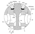
- the plate-like ring member 20E is held between (the downward surface of) the guide member 20D constituting the guide hole 19 and (the upward surface of) the sheet member 20B.
- the plate-like ring member 20E is held via a rubber O ring 20F (in a compressed state) It may be fixed.
- the inner end (cylindrical part 20Eb) of the plate-like ring member 20E is curved to the low pressure side (that is, the pressure sensing chamber 45, Ps inlet / outlet 27 side), and in the example shown in FIG.
- the inner end (cylindrical portion 20Eb) of the ring member 20E is curved on the high pressure side (that is, the valve chamber 21 and the Pd inlet 25 side) (see also FIGS. 6 and 7).
- the O-ring 20F may be disposed on the upper surface side (guide member 20D side) of the plate-like ring member 20E, or may be disposed on the lower surface side (sheet member 20B side). It may be disposed on the lower surface.
- the O-ring 20F may be disposed on the upper surface side (guide member 20D side) of the plate-like ring member 20E, or may be disposed on the lower surface side (sheet member 20B side). It may be disposed on the lower surface.
- the upper surface side of the plate-like ring member 20E (that is, the plate-like ring member 20E It is preferable to arrange in the compression state on the opposite side to the valve chamber 21 side of Also in the examples shown in FIGS. 18 and 19, the plate-like ring member 20E may be molded by being incorporated into the control valve or after being incorporated, as in the above-described embodiments.
- the guide member constituting the guide hole 19 (the outer surface of the main valve body 10) is slidably brought into contact with the plate-like ring member 20E. 20D and the sheet member 20B), for example, as shown in FIG. 20, the plate-like ring member 20E ′ is held and fixed to the main valve body 10, and the outer end Is formed between the valve chamber 21 and the pressure sensing chamber 45 (formed between the main valve body 10 and the guide hole 19) by sliding the cylindrical portion 20Eb ') on the inner wall (inner periphery) of the guide hole 19 The sliding surface gap may be sealed. Further, in this case, it is needless to say that the plate-like ring member 20E 'may be held and fixed via the rubber O-ring 20F (in a compressed state).
- Control valve for variable displacement compressor (first embodiment) 2 Control valve for variable displacement compressor (2nd embodiment) 3 Control valve for variable displacement compressor (third embodiment) 10 main valve body 10a main valve body portion 10b lower diameter portion 10c middle fitting portion 10d upper small diameter portion 10k hook-shaped locking portion 11 main valve portion 12 auxiliary valve portion 15 auxiliary valve body 16 internal valve relief passage 16A internal valve body Passage 16B through escape hole 17 interior member 17B sub valve body 18 accommodation hole 19 guide hole 20 guide body 20A main body member 20B seat member 20Ba central hole 20C concave hole 20D guide member 20Da central hole 20E plate ring member 20F O ring 21 valve chamber 22 valve port 23 sub valve seat section 24 stopper section 25 Pd inlet port 25s horizontal hole 26 Pc inlet / outlet chamber (in / out port) 27 Ps inlet / outlet 28 Ps inlet / outlet chamber 30 electromagnetic actuator 30 A solenoid portion 32 coil 33 stator 34 suction element 37 plunger 40 bellows device (pressure sensitive response member) 45 pressure sensing chamber 46 push rod 50 valve closing
Landscapes
- Engineering & Computer Science (AREA)
- General Engineering & Computer Science (AREA)
- Mechanical Engineering (AREA)
- Compressors, Vaccum Pumps And Other Relevant Systems (AREA)
- Magnetically Actuated Valves (AREA)
Abstract
Description
<第1実施形態>
図1及び図2は、それぞれ本発明に係る可変容量型圧縮機用制御弁の第1実施形態を示す縦断面図であり、図1は主弁:開の状態、図2は主弁:閉の状態を示している。また、図3及び図4は、それぞれ図1及び図2のA部拡大図である。
図示実施形態の制御弁1は、基本的に、弁口22が設けられた弁本体20と、弁口22を開閉するための主弁体10と、該主弁体10を弁口開閉方向(上下方向)に移動させるための電磁式アクチュエータ30と、感圧応動部材としてのベローズ装置40とを備えている。
次に、上記構成とされた制御弁1の動作を概説する。
図8~図11は、それぞれ本発明に係る可変容量型圧縮機用制御弁の第2実施形態を示す縦断面図であり、図8は主弁:開、副弁:閉の状態(通常制御時)、図9及び図10は主弁:閉、副弁:閉の状態(圧縮機起動移行時)、図11は主弁:閉、副弁:開の状態(圧縮機起動時)を示している。また、図12は、図8のB部拡大図である。
図示実施形態の制御弁2は、基本的に、弁口22が設けられた弁本体20と、弁口22を開閉するための主弁体10と、該主弁体10を弁口開閉方向(上下方向)に移動させるための電磁式アクチュエータ30と、感圧応動部材としてのベローズ装置40とを備えている。
次に、上記構成とされた制御弁2の動作を概説する。
図14~図16は、それぞれ本発明に係る可変容量型圧縮機用制御弁の第3実施形態を示す縦断面図であり、図14は主弁:開、副弁:閉の状態(通常制御時)、図15は主弁:閉、副弁:閉の状態(圧縮機起動移行時)、図16は主弁:閉、副弁:開の状態(圧縮機起動時)を示している。また、図17は、図14のC部拡大図である。
図示実施形態の制御弁3では、上記第2実施形態の制御弁2におけるプランジャ37の下面に設けられた筒状脚部37a、弁本体20の弁本体内連通路16A、弁本体20のガイド部材20Dに外挿される筒状部15bを持つ副弁体15等が省略され、プランジャ37に内挿固定された内装部材17が副弁体17Bとされ、プッシュロッド46の大径部46eの形成される段差部46cとの間に縮装されたプランジャばね47により副弁体(内装部材)17Bが下方に付勢された状態で当該副弁体17Bとプランジャ37とが一緒に上下動するようになっている。このプランジャばね47(の圧縮力)により、副弁体17Bが後述する弁内逃がし通路16を閉じる方向に付勢されるとともに、プッシュロッド46を介して前記ベローズ装置40が感圧室45内で保持されている。
次に、上記構成とされた制御弁3の動作を概説する。
2 可変容量型圧縮機用制御弁(第2実施形態)
3 可変容量型圧縮機用制御弁(第3実施形態)
10 主弁体
10a 主弁体部
10b 下部小径部
10c 中間嵌挿部
10d 上部小径部
10k 鍔状係止部
11 主弁部
12 副弁部
15 副弁体
16 弁内逃がし通路
16A 弁本体内連通路
16B 貫通逃がし孔
17 内装部材
17B 副弁体
18 収容穴
19 案内孔
20 弁本体
20A 本体部材
20B シート部材
20Ba 中央穴
20C 凹穴
20D ガイド部材
20Da 中央穴
20E 板状リング部材
20F Oリング
21 弁室
22 弁口
23 副弁シート部
24 ストッパ部
25 Pd導入口
25s 横孔
26 Pc入出室(入出口)
27 Ps入出口
28 Ps入出室
30 電磁式アクチュエータ
30A ソレノイド部
32 コイル
33 ステータ
34 吸引子
37 プランジャ
40 ベローズ装置(感圧応動部材)
45 感圧室
46 プッシュロッド
50 閉弁ばね
51 閉弁ばね
Claims (10)
- 主弁体部を有する主弁体と、
前記主弁体が摺動自在に嵌挿される案内孔、前記主弁体部が接離する弁口が設けられた弁室、及び圧縮機の吸入室に連通するPs入出口を有し、前記弁口より上流側に圧縮機の吐出室に連通するPd導入口が設けられるとともに、前記弁口より下流側に前記圧縮機のクランク室に連通するPc入出口が設けられた弁本体と、
前記主弁体を弁口開閉方向に移動させるための電磁式アクチュエータと、
前記圧縮機から吸入圧力Psが前記Ps入出口を介して導入される感圧室と、
前記感圧室の圧力に応じて前記主弁体を弁口開閉方向に付勢する感圧応動部材と、
前記案内孔と前記主弁体との間に介装された板状リング部材であって、その内側あるいは外側の端部が湾曲して筒状に成型されて筒状部を構成しており、当該筒状部が前記主弁体の外壁もしくは前記案内孔の内壁に摺接せしめられて前記弁室又は前記Pd導入口と前記感圧室又は前記Ps入出口との間をシールする板状リング部材と、
を有することを特徴とする可変容量型圧縮機用制御弁。 - 前記案内孔における前記板状リング部材より前記弁室側の部分と前記主弁体との間に隙間が設けられていることを特徴とする請求項1に記載の可変容量型圧縮機用制御弁。
- 前記板状リング部材は、その内端に前記筒状部が構成されており、当該筒状部が前記主弁体の外壁に摺接せしめられるようにして、前記案内孔に保持固定されていることを特徴とする請求項1又は2に記載の可変容量型圧縮機用制御弁。
- 前記板状リング部材は、前記弁本体の前記案内孔を構成する2つの部材間に挟持されていることを特徴とする請求項3に記載の可変容量型圧縮機用制御弁。
- 前記2つの部材は圧入によって互いに固定されていることを特徴とする請求項4に記載の可変容量型圧縮機用制御弁。
- 前記2つの部材の少なくとも一方に、前記電磁式アクチュエータのプランジャの移動規制を行うストッパ部が設けられていることを特徴とする請求項4又は5に記載の可変容量型圧縮機用制御弁。
- 前記板状リング部材は、Oリングを介して前記案内孔又は前記主弁体に保持固定されていることを特徴とする請求項1から6のいずれか一項に記載の可変容量型圧縮機用制御弁。
- 前記Oリングは、前記板状リング部材の前記弁室側とは反対側に配置されていることを特徴とする請求項7に記載の可変容量型圧縮機用制御弁。
- 前記板状リング部材は、その外端に前記筒状部が構成されており、当該筒状部が前記案内孔の内壁に摺接せしめられるようにして、前記主弁体に保持固定されていることを特徴とする請求項1又は2に記載の可変容量型圧縮機用制御弁。
- 前記クランク室の圧力Pcを前記Ps入出口を介して前記圧縮機の吸入室に逃がすための弁内逃がし通路が前記弁本体内又は前記主弁体内に設けられるとともに、前記弁内逃がし通路を開閉する副弁体が設けられていることを特徴とする請求項1から9のいずれか一項に記載の可変容量型圧縮機用制御弁。
Priority Applications (4)
| Application Number | Priority Date | Filing Date | Title |
|---|---|---|---|
| KR1020207008759A KR102280349B1 (ko) | 2017-11-07 | 2018-10-29 | 가변 용량형 압축기용 제어 밸브 |
| JP2019552724A JPWO2019093166A1 (ja) | 2017-11-07 | 2018-10-29 | 可変容量型圧縮機用制御弁 |
| EP18876297.5A EP3670908A4 (en) | 2017-11-07 | 2018-10-29 | CONTROL VALVE FOR A COMPRESSOR WITH VARIABLE DISPLACEMENT |
| CN201880072029.7A CN111315986A (zh) | 2017-11-07 | 2018-10-29 | 可变容量型压缩机用控制阀 |
Applications Claiming Priority (2)
| Application Number | Priority Date | Filing Date | Title |
|---|---|---|---|
| JP2017-214870 | 2017-11-07 | ||
| JP2017214870 | 2017-11-07 |
Publications (1)
| Publication Number | Publication Date |
|---|---|
| WO2019093166A1 true WO2019093166A1 (ja) | 2019-05-16 |
Family
ID=66437673
Family Applications (1)
| Application Number | Title | Priority Date | Filing Date |
|---|---|---|---|
| PCT/JP2018/040040 Ceased WO2019093166A1 (ja) | 2017-11-07 | 2018-10-29 | 可変容量型圧縮機用制御弁 |
Country Status (5)
| Country | Link |
|---|---|
| EP (1) | EP3670908A4 (ja) |
| JP (1) | JPWO2019093166A1 (ja) |
| KR (1) | KR102280349B1 (ja) |
| CN (1) | CN111315986A (ja) |
| WO (1) | WO2019093166A1 (ja) |
Citations (7)
| Publication number | Priority date | Publication date | Assignee | Title |
|---|---|---|---|---|
| JPH0375359U (ja) * | 1989-11-24 | 1991-07-29 | ||
| JP2010185285A (ja) | 2009-02-10 | 2010-08-26 | Fuji Koki Corp | 制御弁 |
| JP2011043102A (ja) | 2009-08-21 | 2011-03-03 | Tgk Co Ltd | 可変容量圧縮機用制御弁 |
| JP2013130126A (ja) | 2011-12-21 | 2013-07-04 | Fuji Koki Corp | 可変容量型圧縮機用制御弁 |
| JP2016127978A (ja) | 2016-02-25 | 2016-07-14 | サミー株式会社 | ぱちんこ遊技機 |
| JP2016160752A (ja) * | 2015-02-26 | 2016-09-05 | 尼寺空圧工業株式会社 | 空気圧縮機 |
| JP2017110540A (ja) * | 2015-12-16 | 2017-06-22 | 株式会社不二工機 | 可変容量型圧縮機用制御弁 |
Family Cites Families (5)
| Publication number | Priority date | Publication date | Assignee | Title |
|---|---|---|---|---|
| WO1999052787A1 (en) * | 1998-04-16 | 1999-10-21 | Furon Company | Rebuildable radial lip seal |
| DE602004007451T2 (de) * | 2003-10-08 | 2008-03-13 | Pacific Industrial Co., Ltd., Ogaki | Druckregelventil |
| JP2005133932A (ja) * | 2003-10-08 | 2005-05-26 | Pacific Ind Co Ltd | 圧力制御弁 |
| CN101166924A (zh) * | 2005-04-27 | 2008-04-23 | 伊格尔工业股份有限公司 | 密封结构和使用了该密封结构的控制阀 |
| EP3059445B1 (en) * | 2015-02-23 | 2020-06-24 | TGK CO., Ltd. | Electromagnetic control valve of a variable displacement compressor |
-
2018
- 2018-10-29 KR KR1020207008759A patent/KR102280349B1/ko not_active Expired - Fee Related
- 2018-10-29 JP JP2019552724A patent/JPWO2019093166A1/ja not_active Ceased
- 2018-10-29 WO PCT/JP2018/040040 patent/WO2019093166A1/ja not_active Ceased
- 2018-10-29 CN CN201880072029.7A patent/CN111315986A/zh active Pending
- 2018-10-29 EP EP18876297.5A patent/EP3670908A4/en not_active Withdrawn
Patent Citations (7)
| Publication number | Priority date | Publication date | Assignee | Title |
|---|---|---|---|---|
| JPH0375359U (ja) * | 1989-11-24 | 1991-07-29 | ||
| JP2010185285A (ja) | 2009-02-10 | 2010-08-26 | Fuji Koki Corp | 制御弁 |
| JP2011043102A (ja) | 2009-08-21 | 2011-03-03 | Tgk Co Ltd | 可変容量圧縮機用制御弁 |
| JP2013130126A (ja) | 2011-12-21 | 2013-07-04 | Fuji Koki Corp | 可変容量型圧縮機用制御弁 |
| JP2016160752A (ja) * | 2015-02-26 | 2016-09-05 | 尼寺空圧工業株式会社 | 空気圧縮機 |
| JP2017110540A (ja) * | 2015-12-16 | 2017-06-22 | 株式会社不二工機 | 可変容量型圧縮機用制御弁 |
| JP2016127978A (ja) | 2016-02-25 | 2016-07-14 | サミー株式会社 | ぱちんこ遊技機 |
Non-Patent Citations (1)
| Title |
|---|
| See also references of EP3670908A4 |
Also Published As
| Publication number | Publication date |
|---|---|
| EP3670908A1 (en) | 2020-06-24 |
| CN111315986A (zh) | 2020-06-19 |
| KR20200047611A (ko) | 2020-05-07 |
| EP3670908A4 (en) | 2021-01-20 |
| JPWO2019093166A1 (ja) | 2020-11-19 |
| KR102280349B1 (ko) | 2021-07-22 |
Similar Documents
| Publication | Publication Date | Title |
|---|---|---|
| JP7118568B2 (ja) | 容量制御弁及び容量制御弁の制御方法 | |
| JP6395696B2 (ja) | 可変容量型圧縮機用制御弁 | |
| JP5202117B2 (ja) | 減圧弁 | |
| JP4897261B2 (ja) | 真空バルブ | |
| JP6632503B2 (ja) | 可変容量型圧縮機用制御弁 | |
| CN107314577B (zh) | 膨胀阀 | |
| JP2009068568A (ja) | サックバックバルブ | |
| JP6355617B2 (ja) | 可変容量型圧縮機用制御弁 | |
| EP0902188B1 (en) | Screw compressor | |
| US20120020814A1 (en) | Control valve for variable displacement compressor | |
| WO2019146389A1 (ja) | 可変容量型圧縮機用制御弁 | |
| US11131392B2 (en) | Suck-back valve | |
| WO2019093166A1 (ja) | 可変容量型圧縮機用制御弁 | |
| JP2007285159A (ja) | 可変容量型圧縮機用制御弁 | |
| WO2020110427A1 (ja) | 可変容量型圧縮機用制御弁 | |
| JP2020169573A (ja) | 可変容量型圧縮機用制御弁 | |
| WO2019039053A1 (ja) | 可変容量型圧縮機用制御弁 | |
| JPH06283081A (ja) | 圧力応答電気スイッチ | |
| JP2019039377A (ja) | 可変容量型圧縮機用制御弁 | |
| JP2007120522A (ja) | 真空弁 | |
| JPH06340254A (ja) | プロポーショニングバルブ | |
| JP4558616B2 (ja) | 圧力制御弁の弁体及び圧力制御弁 | |
| JP6708911B2 (ja) | 可変容量型圧縮機用制御弁 | |
| WO2019146388A1 (ja) | 可変容量型圧縮機用制御弁 | |
| CN120332539A (zh) | 电驱动阀 |
Legal Events
| Date | Code | Title | Description |
|---|---|---|---|
| 121 | Ep: the epo has been informed by wipo that ep was designated in this application |
Ref document number: 18876297 Country of ref document: EP Kind code of ref document: A1 |
|
| ENP | Entry into the national phase |
Ref document number: 20207008759 Country of ref document: KR Kind code of ref document: A |
|
| ENP | Entry into the national phase |
Ref document number: 2018876297 Country of ref document: EP Effective date: 20200319 |
|
| ENP | Entry into the national phase |
Ref document number: 2019552724 Country of ref document: JP Kind code of ref document: A |
|
| NENP | Non-entry into the national phase |
Ref country code: DE |