WO2019097606A1 - 車両 - Google Patents
車両 Download PDFInfo
- Publication number
- WO2019097606A1 WO2019097606A1 PCT/JP2017/041105 JP2017041105W WO2019097606A1 WO 2019097606 A1 WO2019097606 A1 WO 2019097606A1 JP 2017041105 W JP2017041105 W JP 2017041105W WO 2019097606 A1 WO2019097606 A1 WO 2019097606A1
- Authority
- WO
- WIPO (PCT)
- Prior art keywords
- internal combustion
- combustion engine
- fuel consumption
- power
- mechanical energy
- Prior art date
- Legal status (The legal status is an assumption and is not a legal conclusion. Google has not performed a legal analysis and makes no representation as to the accuracy of the status listed.)
- Ceased
Links
Images


Classifications
-
- B—PERFORMING OPERATIONS; TRANSPORTING
- B60—VEHICLES IN GENERAL
- B60W—CONJOINT CONTROL OF VEHICLE SUB-UNITS OF DIFFERENT TYPE OR DIFFERENT FUNCTION; CONTROL SYSTEMS SPECIALLY ADAPTED FOR HYBRID VEHICLES; ROAD VEHICLE DRIVE CONTROL SYSTEMS FOR PURPOSES NOT RELATED TO THE CONTROL OF A PARTICULAR SUB-UNIT
- B60W10/00—Conjoint control of vehicle sub-units of different type or different function
- B60W10/04—Conjoint control of vehicle sub-units of different type or different function including control of propulsion units
- B60W10/08—Conjoint control of vehicle sub-units of different type or different function including control of propulsion units including control of electric propulsion units, e.g. motors or generators
-
- B—PERFORMING OPERATIONS; TRANSPORTING
- B60—VEHICLES IN GENERAL
- B60K—ARRANGEMENT OR MOUNTING OF PROPULSION UNITS OR OF TRANSMISSIONS IN VEHICLES; ARRANGEMENT OR MOUNTING OF PLURAL DIVERSE PRIME-MOVERS IN VEHICLES; AUXILIARY DRIVES FOR VEHICLES; INSTRUMENTATION OR DASHBOARDS FOR VEHICLES; ARRANGEMENTS IN CONNECTION WITH COOLING, AIR INTAKE, GAS EXHAUST OR FUEL SUPPLY OF PROPULSION UNITS IN VEHICLES
- B60K6/00—Arrangement or mounting of plural diverse prime-movers for mutual or common propulsion, e.g. hybrid propulsion systems comprising electric motors and internal combustion engines
- B60K6/20—Arrangement or mounting of plural diverse prime-movers for mutual or common propulsion, e.g. hybrid propulsion systems comprising electric motors and internal combustion engines the prime-movers consisting of electric motors and internal combustion engines, e.g. HEVs
- B60K6/42—Arrangement or mounting of plural diverse prime-movers for mutual or common propulsion, e.g. hybrid propulsion systems comprising electric motors and internal combustion engines the prime-movers consisting of electric motors and internal combustion engines, e.g. HEVs characterised by the architecture of the hybrid electric vehicle
- B60K6/44—Series-parallel type
- B60K6/445—Differential gearing distribution type
-
- B—PERFORMING OPERATIONS; TRANSPORTING
- B60—VEHICLES IN GENERAL
- B60W—CONJOINT CONTROL OF VEHICLE SUB-UNITS OF DIFFERENT TYPE OR DIFFERENT FUNCTION; CONTROL SYSTEMS SPECIALLY ADAPTED FOR HYBRID VEHICLES; ROAD VEHICLE DRIVE CONTROL SYSTEMS FOR PURPOSES NOT RELATED TO THE CONTROL OF A PARTICULAR SUB-UNIT
- B60W10/00—Conjoint control of vehicle sub-units of different type or different function
- B60W10/04—Conjoint control of vehicle sub-units of different type or different function including control of propulsion units
- B60W10/06—Conjoint control of vehicle sub-units of different type or different function including control of propulsion units including control of combustion engines
-
- B—PERFORMING OPERATIONS; TRANSPORTING
- B60—VEHICLES IN GENERAL
- B60W—CONJOINT CONTROL OF VEHICLE SUB-UNITS OF DIFFERENT TYPE OR DIFFERENT FUNCTION; CONTROL SYSTEMS SPECIALLY ADAPTED FOR HYBRID VEHICLES; ROAD VEHICLE DRIVE CONTROL SYSTEMS FOR PURPOSES NOT RELATED TO THE CONTROL OF A PARTICULAR SUB-UNIT
- B60W20/00—Control systems specially adapted for hybrid vehicles
- B60W20/10—Controlling the power contribution of each of the prime movers to meet required power demand
- B60W20/11—Controlling the power contribution of each of the prime movers to meet required power demand using model predictive control [MPC] strategies, i.e. control methods based on models predicting performance
-
- B—PERFORMING OPERATIONS; TRANSPORTING
- B60—VEHICLES IN GENERAL
- B60W—CONJOINT CONTROL OF VEHICLE SUB-UNITS OF DIFFERENT TYPE OR DIFFERENT FUNCTION; CONTROL SYSTEMS SPECIALLY ADAPTED FOR HYBRID VEHICLES; ROAD VEHICLE DRIVE CONTROL SYSTEMS FOR PURPOSES NOT RELATED TO THE CONTROL OF A PARTICULAR SUB-UNIT
- B60W30/00—Purposes of road vehicle drive control systems not related to the control of a particular sub-unit, e.g. of systems using conjoint control of vehicle sub-units
- B60W30/18—Propelling the vehicle
- B60W30/188—Controlling power parameters of the driveline, e.g. determining the required power
- B60W30/1882—Controlling power parameters of the driveline, e.g. determining the required power characterised by the working point of the engine, e.g. by using engine output chart
-
- B—PERFORMING OPERATIONS; TRANSPORTING
- B60—VEHICLES IN GENERAL
- B60W—CONJOINT CONTROL OF VEHICLE SUB-UNITS OF DIFFERENT TYPE OR DIFFERENT FUNCTION; CONTROL SYSTEMS SPECIALLY ADAPTED FOR HYBRID VEHICLES; ROAD VEHICLE DRIVE CONTROL SYSTEMS FOR PURPOSES NOT RELATED TO THE CONTROL OF A PARTICULAR SUB-UNIT
- B60W2510/00—Input parameters relating to a particular sub-units
- B60W2510/06—Combustion engines, Gas turbines
- B60W2510/0657—Engine torque
-
- B—PERFORMING OPERATIONS; TRANSPORTING
- B60—VEHICLES IN GENERAL
- B60W—CONJOINT CONTROL OF VEHICLE SUB-UNITS OF DIFFERENT TYPE OR DIFFERENT FUNCTION; CONTROL SYSTEMS SPECIALLY ADAPTED FOR HYBRID VEHICLES; ROAD VEHICLE DRIVE CONTROL SYSTEMS FOR PURPOSES NOT RELATED TO THE CONTROL OF A PARTICULAR SUB-UNIT
- B60W2510/00—Input parameters relating to a particular sub-units
- B60W2510/06—Combustion engines, Gas turbines
- B60W2510/0666—Engine power
-
- B—PERFORMING OPERATIONS; TRANSPORTING
- B60—VEHICLES IN GENERAL
- B60W—CONJOINT CONTROL OF VEHICLE SUB-UNITS OF DIFFERENT TYPE OR DIFFERENT FUNCTION; CONTROL SYSTEMS SPECIALLY ADAPTED FOR HYBRID VEHICLES; ROAD VEHICLE DRIVE CONTROL SYSTEMS FOR PURPOSES NOT RELATED TO THE CONTROL OF A PARTICULAR SUB-UNIT
- B60W2710/00—Output or target parameters relating to a particular sub-units
- B60W2710/06—Combustion engines, Gas turbines
- B60W2710/0644—Engine speed
-
- Y—GENERAL TAGGING OF NEW TECHNOLOGICAL DEVELOPMENTS; GENERAL TAGGING OF CROSS-SECTIONAL TECHNOLOGIES SPANNING OVER SEVERAL SECTIONS OF THE IPC; TECHNICAL SUBJECTS COVERED BY FORMER USPC CROSS-REFERENCE ART COLLECTIONS [XRACs] AND DIGESTS
- Y02—TECHNOLOGIES OR APPLICATIONS FOR MITIGATION OR ADAPTATION AGAINST CLIMATE CHANGE
- Y02T—CLIMATE CHANGE MITIGATION TECHNOLOGIES RELATED TO TRANSPORTATION
- Y02T10/00—Road transport of goods or passengers
- Y02T10/10—Internal combustion engine [ICE] based vehicles
- Y02T10/40—Engine management systems
-
- Y—GENERAL TAGGING OF NEW TECHNOLOGICAL DEVELOPMENTS; GENERAL TAGGING OF CROSS-SECTIONAL TECHNOLOGIES SPANNING OVER SEVERAL SECTIONS OF THE IPC; TECHNICAL SUBJECTS COVERED BY FORMER USPC CROSS-REFERENCE ART COLLECTIONS [XRACs] AND DIGESTS
- Y02—TECHNOLOGIES OR APPLICATIONS FOR MITIGATION OR ADAPTATION AGAINST CLIMATE CHANGE
- Y02T—CLIMATE CHANGE MITIGATION TECHNOLOGIES RELATED TO TRANSPORTATION
- Y02T10/00—Road transport of goods or passengers
- Y02T10/60—Other road transportation technologies with climate change mitigation effect
- Y02T10/62—Hybrid vehicles
-
- Y—GENERAL TAGGING OF NEW TECHNOLOGICAL DEVELOPMENTS; GENERAL TAGGING OF CROSS-SECTIONAL TECHNOLOGIES SPANNING OVER SEVERAL SECTIONS OF THE IPC; TECHNICAL SUBJECTS COVERED BY FORMER USPC CROSS-REFERENCE ART COLLECTIONS [XRACs] AND DIGESTS
- Y02—TECHNOLOGIES OR APPLICATIONS FOR MITIGATION OR ADAPTATION AGAINST CLIMATE CHANGE
- Y02T—CLIMATE CHANGE MITIGATION TECHNOLOGIES RELATED TO TRANSPORTATION
- Y02T10/00—Road transport of goods or passengers
- Y02T10/80—Technologies aiming to reduce greenhouse gasses emissions common to all road transportation technologies
- Y02T10/84—Data processing systems or methods, management, administration
Definitions
- Embodiments of the present invention relate to vehicles.
- a hybrid vehicle including an internal combustion engine and a battery includes, for example, a power split mechanism that distributes mechanical energy output from the internal combustion engine to a generator side and a drive train side.
- the generator of the vehicle operates as a motor, ie there is a negative mode in which the sun gear rotates in reverse, and when the vehicle is operating in the negative mode, the output power of the generator Is transmitted to the wheel side via the power split mechanism, so the power transmission efficiency of the vehicle is degraded.
- An embodiment of the present invention has been made in view of the above circumstances, and an object thereof is to provide a vehicle with an improved power transmission efficiency.
- a vehicle includes an internal combustion engine, a power split mechanism that divides and outputs mechanical energy output from the internal combustion engine, and a generator that converts mechanical energy transmitted from the power split mechanism into electrical energy.
- Drive by a converter for controlling the operation of the generator, an inverter connected to the converter via a DC link, a battery connected to the DC link, a motor operated by energy supplied from the inverter, and the motor And a control unit that increases the rotational speed of the internal combustion engine when the direction of rotation of the generator is negative.
- FIG. 1 is a block diagram schematically showing the configuration of a vehicle according to the first embodiment.
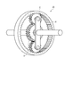
- FIG. 2 is a diagram schematically showing an example of the configuration of the power split mechanism.
- FIG. 3 is a diagram for explaining an example of the relationship between the sun gear of the power split mechanism, the ring gear, and the rotational speed of the planetary carrier.
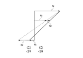
- FIG. 4 is a diagram for explaining an example of the relationship between the sun gear of the power split mechanism, the ring gear, and the rotational speed of the planetary carrier.
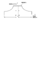
- FIG. 5 is a diagram showing an example of a generator frequency range that can be continuously operated in the vehicle of the embodiment.
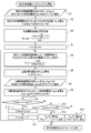
- FIG. 6 is a flow chart for explaining an example of the method of determining the number of revolutions of the internal combustion engine according to the first embodiment.
- FIG. 1 is a block diagram schematically showing the configuration of a vehicle according to the first embodiment.
- the vehicle of the present embodiment includes an internal combustion engine 10, a power split mechanism 20, a generator 30, a converter 40, an inverter 50, a motor 60, a power coupling mechanism 70, a battery 80, wheels WL, a vehicle And an ECU 90.
- the internal combustion engine 10 is a prime mover that generates mechanical energy for driving a vehicle, such as a gasoline engine or a diesel engine.
- Power split device 20 splits mechanical energy Pe generated by internal combustion engine 10 into energy Pg supplied to generator 30 side and energy Pr supplied to wheel WL side (drive train side) for supply. Do.
- FIG. 2 schematically shows an example of the configuration of power split device 20.
- the power split mechanism 20 includes, for example, a sun gear S, a planetary rear gear P circumscribed to the sun gear S, a ring gear R to which the planetary rear gear P is inscribed, and a planetary carrier C rotating along a track of the planetary rear gear P.
- the planetary carrier C is rotated by the mechanical energy Pe generated by the internal combustion engine 10.
- the rotational power of the sun gear S is transmitted to the generator 30.
- the rotational power of the ring gear R is transmitted to the power coupling mechanism 70.
- the generator 30 converts mechanical energy Pg supplied via the sun gear S of the power split mechanism 20 into electrical energy.
- the generator 30 is, for example, a motor provided with a rotor interlocking with the sun gear S and a stator, and outputs three-phase AC power.
- the converter 40 is a control means for controlling the operation of the generator 30, and converts the three-phase AC power output from the generator 30 into DC power for regeneration operation, and DC power supplied from the DC link Are converted into three-phase alternating current power and supplied to the generator 30, and the power generator 30 is made to perform a power running operation.
- Converter 40 is connected to inverter 50 and battery 80 via a DC link.
- the motor 60 is driven by AC power supplied from the inverter 50, converts electrical energy into mechanical energy Pm, and outputs the mechanical energy Pm to the power coupling mechanism 70.
- the power coupling mechanism 70 transmits energy Pout obtained by combining the mechanical energy Pg transmitted from the ring gear R of the internal combustion engine 10 and the mechanical energy Pm supplied from the inverter 50 to an axle (not shown).
- the wheel WL is rotationally driven via an axle.
- a vehicle ECU (electric control unit) 90 is a control unit that controls the internal combustion engine 10, the generator 30, the converter 40, the inverter 50, the motor 60, and the battery 80 to operate in cooperation with one another.
- the vehicle ECU 90 is an arithmetic unit including, for example, at least one processor such as a CPU (central processing unit) or an MPU (micro processing unit) and a memory in which a program executed by the processor is recorded.
- the rotation speed of the planetary carrier C (the rotation speed of the internal combustion engine 10) is constant, the rotation speed of the sun gear S may be lowered to be in the negative direction. That is, the operation of the generator 30 changes from regeneration to power running.
- FIG. 4 is a view for explaining an example of the relationship between the rotational speed of the sun gear S, the ring gear R, and the planetary carrier C of the power split mechanism 20. As shown in FIG. This example is an example of a negative mode in which the planetary carrier C and the ring gear R rotate in the positive direction, and the sun gear S rotates in the negative direction.
- the ratio of the number of teeth Zs of the sun gear S of the power split mechanism 20 to the number of teeth Zr of the ring gear R is 1: 2 and the energy transfer efficiency from the generator 30 to the motor 60 is 85.6%.
- the power transmission efficiency of the entire vehicle will be described by taking, as an example, the case where the respective energy transmission efficiencies of the split mechanism 20 and the power coupling mechanism 70 are 98%.
- the rotational speed of the sun gear S (the rotational speed of the generator 30) becomes -800 rpm to -200 rpm. It shifted in the positive direction. Further, as a result of raising the rotational speed of the internal combustion engine 10 while keeping the output of the internal combustion engine 10 constant, the torque (engine torque) of the planetary carrier C decreases and the torque of the generator 30 also decreases.
- FIG. 5 is a diagram showing an example of a continuously operable generator frequency range in the vehicle of the embodiment.
- the conduction time of a specific element of the converter 40 becomes longer, and further, when the frequency of the power output from the generator 30 becomes 0 Hz (DC), the specific element Current continues to flow, and the element temperature rises. In order to avoid this state, it is desirable to define the range in which the generator 30 operates continuously.
- the rotational speed Ns' of the generator 30 after the rotational speed shift of the internal combustion engine 10 (when the frequency -f0 of the generator 30) is expressed by the following (Equation 3), which is shown in the above (Equation 2)
- the upper limit of the shift amount when the vehicle is operating in the negative mode is expressed by (Expression 5).
- the operating point of the internal combustion engine 10 at which the fuel efficiency of the vehicle is optimum is searched from the trade-off relationship between the power transmission efficiency from the internal combustion engine 10 to the wheel WL and the efficiency of the internal combustion engine 10.
- FIG. 6 is a flow chart for explaining an example of the method of determining the number of revolutions of the internal combustion engine according to the first embodiment.
- the vehicle ECU 90 executes the following method of determining the number of revolutions of the internal combustion engine 10 at least when the vehicle is operating in the negative mode, and the vehicle ECU 90 has a negative direction of rotation of the generator 30. At one time, it is determined that the vehicle is operating in the negative mode.
- the vehicle ECU 90 uses the fuel consumption amount c0 (g / kWh) read from the memory to calculate the fuel consumption amount C_fuel0 (g) per unit time as the following (Equation 6) (step S2).
- the vehicle ECU 90 uses the internal combustion engine torque Tc_n and the rotational speed Nc_n of the internal combustion engine 10 to generate the internal combustion engine output Pe_n required to output the vehicle required output Pout * at the operating point of the internal combustion engine 10 ) (Step S6).
- the vehicle ECU 90 extracts the fuel consumption amount c_n (g / kWh) per unit energy at the operating point (Pe_n, Nc_n) of the internal combustion engine 10 from the map stored in the memory (step S7)
- the fuel consumption amount C_fuel_n per unit time is calculated by the following (Equation 9) (step S8).
- the vehicle ECU 90 updates the rotational speed Nc_n of the internal combustion engine 10 to Nc_n- ⁇ (step S11).
- Vehicle ECU 90 sets ⁇ as a predetermined positive integer. Further, when operating in the positive mode, the rotational speed Nc_n is set to Nc_n + ⁇ .
- the value of ⁇ may be a fixed value, or may be a value that changes according to the value of the rotational speed Nc_n, for example.
- step S9 when the fuel consumption C_fuel_n is not less than the fuel consumption search variable C_fuel_p (when C_fuel_n ⁇ C_fuel_p is not satisfied), the vehicle ECU 90 compares the fuel consumption search variable C_fuel_p with the fuel throughput C_fuel0 (step S12).
- the vehicle ECU 90 sets the initial operating point (Pe0, Nc0) as the operating point of the internal combustion engine 10 (step S14).
- the search variable C_fuel_p and the initial value of the fuel consumption Comparing the _Fuel0 when the search variable C_fuel_p is smaller than the initial value C_fuel0 fuel consumption, and the operating point the rotational speed of the internal combustion engine 10 corresponding to the search variable C_fuel_p, comprises computing means.
- the vehicle ECU 90 selects a plurality of rotation speeds Nc_n in a range in which the internal combustion engine 10 can continuously operate at a predetermined sampling frequency, and selects the plurality of rotation speeds Nc_n selected.
- the fuel consumption amount in the above may be calculated, and the rotation speed Nc_n at which the fuel consumption amount is minimized and the output power Pe_n corresponding thereto may be determined as the operating point (Pe, Nc). Even in that case, the same effect as the above-described embodiment can be obtained.
- the above-described method of determining the rotational speed of the internal combustion engine 10 can be performed both when the vehicle is operating in the positive mode and when operating in the negative mode.
- the power transmission efficiency can be more effectively achieved by determining the rotational speed in consideration of the fuel consumption of the internal combustion engine 10 and the energy transmission efficiency as described above. While improving it, fuel consumption can be suppressed.
Landscapes
- Engineering & Computer Science (AREA)
- Chemical & Material Sciences (AREA)
- Combustion & Propulsion (AREA)
- Transportation (AREA)
- Mechanical Engineering (AREA)
- Automation & Control Theory (AREA)
- Electric Propulsion And Braking For Vehicles (AREA)
- Hybrid Electric Vehicles (AREA)
Abstract
実施形態による車両は、動力伝達効率を改善した車両を提供するものであって、内燃機関と、内燃機関から出力される機械エネルギーを分割して出力する動力分割機構と、動力分割機構から伝達された機械エネルギーを電気エネルギーに変換する発電機と、発電機の動作を制御するコンバータと、コンバータと直流リンクを介して接続したインバータと、直流リンクに接続したバッテリと、インバータから供給されたエネルギーにより駆動されるモータと、モータから供給された機械エネルギーと動力分割機構から伝達された機械エネルギーとを結合する動力結合機構と、動力結合機構により結合された機械エネルギーにより駆動される車軸と、発電機の回転方向が負方向となったときに、内燃機関の回転数を増加する制御部と、を備える。
Description
本発明の実施形態は、車両に関する。
内燃機関とバッテリとを備えたハイブリッド車両は、例えば、内燃機関から出力される機械エネルギーを発電機側とドライブトレイン側とに分配する動力分割機構を備えている。
動力分割機構として例えば遊星ギアを採用することが可能であって、サンギアと、サンギアに外接したプラネタリアギアと、プラネタリアギアが内接したリングギアと、プラネタリアギアの軌道に沿って回転するプラネタリキャリアと、を備えている。サンギアは、発電機へ動力を伝達する。プラネタリアキャリアは、内燃機関の動力により回転する。リングギアは、車輪へ動力を伝達する。
速度や要求されたトルクの条件により、車両の発電機がモータとして動作する、すなわちサンギアが逆回転するネガティブモードが存在し、車両がネガティブモードで動作している際には、発電機の出力電力が動力分割機構を介して車輪側に伝達されるため、車両の動力伝達効率が悪くなる。
本発明の実施形態は、上記事情を鑑みて成されたものであって、動力伝達効率を改善した車両を提供することを目的とする。
実施形態による車両は、内燃機関と、前記内燃機関から出力される機械エネルギーを分割して出力する動力分割機構と、前記動力分割機構から伝達された機械エネルギーを電気エネルギーに変換する発電機と、前記発電機の動作を制御するコンバータと、前記コンバータと直流リンクを介して接続したインバータと、前記直流リンクに接続したバッテリと、前記インバータから供給されたエネルギーにより動作するモータと、前記モータにより駆動される車軸と、前記発電機の回転方向が負方向となったときに、前記内燃機関の回転数を増加する制御部と、を備える。
以下、実施形態の車両について、図面を参照して説明する。
図1は、第1実施形態の車両の構成を概略的に示すブロック図である。
本実施形態の車両は、内燃機関10と、動力分割機構20と、発電機30と、コンバータ40と、インバータ50と、モータ60と、動力結合機構70と、バッテリ80と、車輪WLと、車両ECU90と、を備えている。
図1は、第1実施形態の車両の構成を概略的に示すブロック図である。
本実施形態の車両は、内燃機関10と、動力分割機構20と、発電機30と、コンバータ40と、インバータ50と、モータ60と、動力結合機構70と、バッテリ80と、車輪WLと、車両ECU90と、を備えている。
内燃機関10は、ガソリンエンジンやディーゼルエンジン等、車両を駆動する機械エネルギーを生成する原動機である。
動力分割機構20は、内燃機関10で生成された機械エネルギーPeを、発電機30側に供給されるエネルギーPgと、車輪WL側(ドライブトレイン側)に供給されるエネルギーPrとに分割して供給する。
動力分割機構20は、内燃機関10で生成された機械エネルギーPeを、発電機30側に供給されるエネルギーPgと、車輪WL側(ドライブトレイン側)に供給されるエネルギーPrとに分割して供給する。
図2は、動力分割機構20の構成の一例を概略的に示す図である。
動力分割機構20は、例えば、サンギアSと、サンギアSに外接したプラネタリアギアPと、プラネタリアギアPが内接したリングギアRと、プラネタリアギアPの軌道に沿って回転するプラネタリキャリアCと、を備えている。本実施形態では、プラネタリキャリアCは、内燃機関10で生成された機械エネルギーPeにより回転する。サンギアSの回転動力は発電機30へ伝達される。リングギアRの回転動力は動力結合機構70に伝達される。
動力分割機構20は、例えば、サンギアSと、サンギアSに外接したプラネタリアギアPと、プラネタリアギアPが内接したリングギアRと、プラネタリアギアPの軌道に沿って回転するプラネタリキャリアCと、を備えている。本実施形態では、プラネタリキャリアCは、内燃機関10で生成された機械エネルギーPeにより回転する。サンギアSの回転動力は発電機30へ伝達される。リングギアRの回転動力は動力結合機構70に伝達される。
発電機30は、動力分割機構20のサンギアSを介して供給される機械エネルギーPgを電気エネルギーに変換する。発電機30は、例えば、サンギアSと連動する回転子と固定子とを備えたモータであって、3相交流電力を出力する。
コンバータ40は、発電機30の動作を制御する制御手段であって、発電機30から出力された3相交流電力を直流電力に変換して回生動作とするとともに、直流リンクから供給される直流電力を3相交流電力に変換して発電機30へ供給し、発電機30を力行動作とする。コンバータ40は直流リンクを介してインバータ50およびバッテリ80と接続している。
インバータ50は、直流リンクから供給された直流電力を交流電力に変換してモータ60へ出力する。また、インバータ50は、モータ60から供給された交流電力を直流電力に変換して直流リンクへ出力する。
モータ60は、インバータ50から供給される交流電力により駆動され、電気エネルギーを機械エネルギーPmに変換して動力結合機構70へ出力する。
動力結合機構70は、内燃機関10のリングギアRから伝達された機械エネルギーPgと、インバータ50から供給された機械エネルギーPmとを結合したエネルギーPoutを車軸(図示せず)へ伝達する。車輪WLは車軸を介して回転駆動される。
動力結合機構70は、内燃機関10のリングギアRから伝達された機械エネルギーPgと、インバータ50から供給された機械エネルギーPmとを結合したエネルギーPoutを車軸(図示せず)へ伝達する。車輪WLは車軸を介して回転駆動される。
バッテリ80は、例えば、複数の2次電池セルを含む組電池を備え、直流リンクから供給される電力により充電可能であり、直流リンクを介して電力を放電可能に構成されている。
車両ECU(electric control unit)90は、内燃機関10、発電機30、コンバータ40、インバータ50、モータ60、および、バッテリ80が互いに連係して動作するように制御する制御部である。車両ECU90は、例えば、CPU(central processing unit)やMPU(micro processing unit)などのプロセッサを少なくとも1つと、プロセッサにより実行されるプログラムが記録されたメモリとを備える演算手段である。
図3は、動力分割機構20のサンギアS、リングギアR、および、プラネタリキャリアCの回転数の関係の一例を説明するための図である。
図3では、プラネタリキャリアCの回転数をNc、サンギアSの回転数をNs、リングギアRの回転数をNr、サンギアSの歯数をZs、リングギアRの歯数をZrとしている。なお、回転数の正(+)方向は、発電機30が回生するときの回転方向である。
図3では、プラネタリキャリアCの回転数をNc、サンギアSの回転数をNs、リングギアRの回転数をNr、サンギアSの歯数をZs、リングギアRの歯数をZrとしている。なお、回転数の正(+)方向は、発電機30が回生するときの回転方向である。
この例は、プラネタリキャリアC、サンギアS、および、リングギアRは、全て正方向に回転しているポジティブモード(内燃機関10から車輪WL側へ向かう方向へ全てのエネルギーが供給されている車両の動作モード)の一例である。プラネタリキャリアCの回転数Ncは内燃機関10の回転数により決まり、リングギアRの回転数Nrは車速により決まる。サンギアSの回転数Nsは、サンギアSの歯数ZrとリングギアRの歯数Zrとの比により決まる。
このとき、プラネタリキャリアCにより生成されるトルクをTc、サンギアSにより生成されるトルクをTs、リングギアRにより生成されるトルクをTrとすると、トルクTcはトルクTsとトルクTrとの和となり、トルクTsとトルクTrとの割合はサンギアSの歯数ZrとリングギアRの歯数Zrとの比により決まる。
車両がポジティブモードで動作しているとき、発電機30は回生する。モータ60は、コンバータ40を介して発電機30から直流リンクへ出力されるエネルギーを利用して、機械エネルギーPmを出力する。一方、動力分割機構20のリングギアRへ伝わるエネルギーPrは車輪WLへ直接伝わり、車両が出力する機械エネルギーPoutは、エネルギーPmとエネルギーPrとの和となる。
ここで、車速が増加するとリングギアRの回転数が増加する。このときに、プラネタリキャリアCの回転数(内燃機関10の回転数)が一定であると、サンギアSの回転数が低下し、負方向となることがある。すなわち、発電機30の動作が回生から力行へと変化する。
図4は、動力分割機構20のサンギアS、リングギアR、および、プラネタリキャリアCの回転数の関係の一例を説明するための図である。この例は、プラネタリキャリアCとリングギアRとが正方向に回転し、サンギアSが負方向に回転しているネガティブモードの一例である。
例えば、プラネタリキャリアCの回転数Ncが一定で、リングギアRの回転数Nrが増加すると、サンギアSの回転数Nsは負となる。すなわち、サンギアSの回転方向がポジティブモードと逆となる。
動力分割機構20がネガティブモードで動作しているときには、リングギアRへ伝わる機械エネルギーPrは、内燃機関10から動力分割機構20へ伝達される機械エネルギーPeと発電機30から動力分割機構20へ伝達される機械エネルギーPgとの和となる。機械エネルギーPgは、モータ60が回生することにより生成される。このため、機械エネルギーPgは、動力分割機構20と動力結合機構70とを経由して車輪WLへ伝達され、車両全体として動力伝達効率が低下する。
そこで、本実施形態では、動力分割機構20がネガティブモードで動作するときに、車両ECUは、プラネタリキャリアCの回転数Ncを正方向にシフトさせ(回転数Ncを増加し)、サンギアSの回転数Nsの絶対値を減少させて機械エネルギーPgを低く抑えることにより、車両全体としての動力伝達効率を改善している。
図4では、ネガティブモードにおいて、プラネタリアキャリアCの回転数Ncを破線で示し、正方向にシフトさせた後の回転数Nc´を実線で示している。この共線図によれば、プラネタリアキャリアCの回転数Ncを正方向にシフトさせると、サンギアSの回転数Nsも正方向にシフトし、その結果、発電機30から動力分割機構20へ伝達される機械エネルギーPgが減少することとなる。
以下に、動力分割機構20のサンギアSの歯数ZsとリングギアRの歯数Zrとの比を1:2とし、発電機30からモータ60までのエネルギー伝達効率を85.6%とし、動力分割機構20と動力結合機構70とのそれぞれのエネルギー伝達効率を98%としたときを例として、車両全体の動力伝達効率について説明する。
このとき、内燃機関10の出力を500kW一定とし、内燃機関10の回転数を1200rpmから1400rpmへ上昇させた場合、サンギアSの回転数(発電機30の回転数)は、-800rpmから-200rpmとなり正方向にシフトした。また、内燃機関10の出力を一定として内燃機関10の回転数を上昇させた結果、プラネタリキャリアCのトルク(エンジントルク)が減少し、発電機30のトルクも減少した。
発電機30の回転数とトルクとが下がった結果、発電機30から出力される機械エネルギーPgが減少し、ネガティブモードにおいてモータ60で回生するエネルギーが小さくなり、車両全体での動力伝達効率は、93.3%から97%へ向上した。
次に、本実施形態の車両における内燃機関の回転数決定方法の一例について説明する。
動力分割機構20がネガティブモードにて動作しているときに、車両の動力伝達効率を向上させるため、内燃機関10の回転数を正方向へシフトさせる(増加させる)が、このシフト量は、発電機30の動作を制御するコンバータ40にて制限される。
動力分割機構20がネガティブモードにて動作しているときに、車両の動力伝達効率を向上させるため、内燃機関10の回転数を正方向へシフトさせる(増加させる)が、このシフト量は、発電機30の動作を制御するコンバータ40にて制限される。
図5は、実施形態の車両において、連続運転可能な発電機周波数範囲の一例を示す図である。
発電機30から出力される電力の周波数が0Hzに近づくほど、コンバータ40の特定の素子の通電時間が長くなり、さらに発電機30から出力される電力の周波数が0Hz(直流)になると特定の素子に電流が流れ続け、素子温度が上昇する。この状態を回避するため、発電機30が連続的な運転を行う範囲を規定することが望ましい。
発電機30から出力される電力の周波数が0Hzに近づくほど、コンバータ40の特定の素子の通電時間が長くなり、さらに発電機30から出力される電力の周波数が0Hz(直流)になると特定の素子に電流が流れ続け、素子温度が上昇する。この状態を回避するため、発電機30が連続的な運転を行う範囲を規定することが望ましい。
ここで、動力分割機構20のサンギアSの歯数をZs、リングギアRの歯数をZr、リングギアRの回転数(rpm)をNr、内燃機関10の回転数シフト前のプラネタリキャリアC(内燃機関)の回転数(rpm)をNc、内燃機関10の回転数シフト後のプラネタリキャリアC(内燃機関)の回転数(rpm)をNc´、内燃機関10の回転数シフト前のサンギアSの回転数(rpm)Ns、内燃機関10の回転数シフト後のサンギアSの回転数(rpm)をNs´、コンバータ40の連続運転できない周波数範囲を-f0(Hz)より大きくf0(Hz)未満、発電機30の極対数をPnとする。
内燃機関10の回転数シフト前後でリングギアRの回転数が変化しない場合、Nc、Nc´、Nr、Ns、Ns´の関係は、下記(式1)及び(式2)で表される。

このとき、内燃機関10の回転数シフト後(発電機30の周波数-f0のとき)の発電機30の回転数Ns´は、下記(式3)で表され、これを上記(式2)に代入すると、シフト後の内燃機関10の回転数Nc´は下記(式4)のように表される。すなわち、下記(式4)で表される回転数Nc´は、発電機30が連続運転できない周波数範囲の下限値(=-f0)に対応する内燃機関10の回転数である。

内燃機関10の回転数シフト量は、Nc´-Ncであるから、車両がネガティブモードで動作している際のシフト量の上限は(式5)で表される。

このように内燃機関10の回転数シフト量の上限を決定することにより、車両全体の動力伝達効率を高めつつ、安定した車両駆動を実現できる。
また、内燃機関10の動作点(出力電力Pe,回転数Nc)は、一般的には、内燃機関10単体の効率が最大となるよう決定される。しかしながら、前述のように、動力分割機構20がネガティブモードで動作している際の動力伝達効率低下の影響は無視できず、内燃機関10単体として最適であっても、車両全体の燃費が最適になるとは限らない。上述のように、内燃機関10から車輪WLへの動力伝達効率を向上するには、内燃機関10の回転数Ncをシフトするのが有効であるが、一方で、内燃機関10単体の効率が低くなってしまう。
そこで、本実施形態では、内燃機関10から車輪WLまでの動力伝達効率と内燃機関10の効率とのトレードオフ関係より、車両の燃費が最適となる内燃機関10の動作点を探索する。
図6は、第1実施形態の内燃機関の回転数決定方法の一例を説明するフローチャートである。なお、車両ECU90は、少なくとも車両がネガティブモードで動作しているときに、以下の内燃機関10の回転数決定方法を実行するものであって、車両ECU90は、発電機30の回転方向が負であるときに車両がネガティブモードで動作していると判断する。
最初に、車両ECU90は、内燃機関10単体での最適な動作点(出力電力Pe0,回転数Nc0)における燃料消費量C_fuel0(g)を算出する。車両ECU90は、内燃機関10の回転数Nc0(rap/s)と出力電力Pe0(kW)とに対応する単位エネルギーあたりの燃料消費量c0(g/kWh)を、例えば、車両ECU90のメモリに予め記録されたマップから読みだす(ステップS1)。
車両ECU90は、メモリから読みだした燃料消費量c0(g/kWh)を用いて、単位時間当たりの燃料消費量C_fuel0(g)を下記(式6)のように算出する(ステップS2)。

次に、車両ECU90は、内燃機関10の回転数の上限Nc_maxを算出する。内燃機関10の回転数の上限Nc_maxは上述の(式4)にて算出される(ステップS3)。
なお、上述の(式4)は、ネガティブモードで動作している際の内燃機関10の回転数の上限値Nc_maxであり、ポジティブモードで動作している際には、内燃機関10の回転数Nc_maxを(式4)のf0の符号を逆にした値(ポジティブモードにおける内燃機関10の回転数の下限値)とする。
なお、上述の(式4)は、ネガティブモードで動作している際の内燃機関10の回転数の上限値Nc_maxであり、ポジティブモードで動作している際には、内燃機関10の回転数Nc_maxを(式4)のf0の符号を逆にした値(ポジティブモードにおける内燃機関10の回転数の下限値)とする。
続いて、車両ECU90は、内燃機関10の回転数Nc_nを回転数の上限Nc_maxとし(ステップS4)、車両要求出力Pout*を出力するために必要な内燃機関トルクTc_nを、下記(式7)を用いて算出する(ステップS5)。

なお、上記(式7)において、Zs:サンギア歯数、Zr:リングギア歯数、ηel:発電機モータシステム効率(発電機30からモータ60までの動力伝達効率)、ηgr:ギア効率(動力分割機構20および動力結合機構70それぞれの動力伝達効率)である。
続いて、車両ECU90は、内燃機関トルクTc_nと内燃機関10の回転数Nc_nとにより、この内燃機関10の動作点で車両要求出力Pout*を出すのに必要な内燃機関出力Pe_nは、(式8)となる(ステップS6)。

次に、車両ECU90は、この内燃機関10の動作点(Pe_n,Nc_n)での単位エネルギーあたりの燃料消費量c_n(g/kWh)を、メモリに格納されたマップより抽出し(ステップS7)、単位時間当たりの燃料消費量C_fuel_nを下記(式9)により算出する(ステップS8)。

車両ECU90は、ステップ8で算出した燃料消費量C_fuel_nと、燃料消費量の探索変数C_fuel_pとを比較する(ステップS9)。なお、探索変数C_fuel_pの初期値は燃料消費量C_fuel0である。
燃料消費量C_fuel_nが探索変数C_fuel_pよりも小さい場合、車両ECU90は、ステップS8で算出した燃料消費量C_fuel_nの値を探索変数C_fuel_pへ格納する(ステップS10)。
次に、車両ECU90は、内燃機関10の回転数Nc_nをNc_n-αに更新する(ステップS11)。なお、車両ECU90は、αを所定の正の整数とする。また、ポジティブモードで動作している際には、回転数Nc_nをNc_n+αとする。αの値は、一定の値であってもよく、例えば回転数Nc_nの値に応じた変化する値であってもよい。
続いて、車両ECU90は、ステップS5へ戻り、ステップS5乃至S8までの演算を行い、更新後の回転数Nc_nを用いて燃料消費量C_fuel_nを算出し(ステップS8)、燃料消費量の探索変数C_fuel_pと燃料消費量C_fuel_nとを比較し(ステップS9)、C_fuel_n≧C_fuel_pとなるまで、探索変数C_fuel_pを前回値より小さい値に更新する動作を繰り返す。
ステップS9において、燃料消費量C_fuel_nが燃料消費量の探索変数C_fuel_p以上である場合(C_fuel_n<C_fuel_pでないとき)、車両ECU90は、燃料消費量の探索変数C_fuel_pと燃料処理量C_fuel0とを比較する(ステップS12)。
車両ECU90は、燃料消費量の探索変数C_fuel_pが初期値C_fuel0未満の場合は、燃料消費量の探索変数C_fuel_pでの動作点(Pe_n‐1,Nc_n‐1)を内燃機関10の動作点とする(ステップS13)。
車両ECU90は、燃料消費量の探索変数C_fuel_pが初期値C_fuel0以上のときには、初期の動作点(Pe0,Nc0)を、内燃機関10の動作点とする(ステップS14)。
すなわち、本実施形態では、車両ECU90は、内燃機関10の最適動作点における単位時間当たりの燃料消費量C_fuel0を燃料消費量C_fuel_nの初期値とし、内燃機関10の回転数上限値Nc_maxを演算し、回転数上限値Nc_maxにおける目標車両出力を実現するために必要な内燃機関10のトルクと出力電力とを演算し、この内燃機関10のトルクと出力電力とにおける、単位時間当たりの燃料消費量C_fuel_n演算し、燃料消費量の初期値C_fuel0を探索変数C_fuel_pの初期値とし、燃料消費量C_fuel_nが探索変数C_fuel_p以上となるまで、内燃機関10の回転数を変化させて探索変数C_fuel_pを燃料消費量C_fuel_nの値に更新し、単位時間当たりの燃料消費量C_fuel_nが探索変数C_fuel_pよりも大きくなったときに、探索変数C_fuel_pと燃料消費量の初期値C_fuel0とを比較し、探索変数C_fuel_pが燃料消費量の初期値C_fuel0よりも小さいときに、探索変数C_fuel_pに対応する内燃機関10の回転数を動作点とする、演算手段を備える。
上記のように内燃機関10の回転数を決定することにより、車両全体としての動力伝達効率を改善し、かつ、燃料消費量を最小化する内燃機関10の動作点を決定することができる。すなわち、本実施形態によれば、動力伝達効率を改善した車両を提供することができる。
本発明のいくつかの実施形態を説明したが、これらの実施形態は、例として提示したものであり、発明の範囲を限定することは意図していない。これら新規な実施形態は、その他の様々な形態で実施されることが可能であり、発明の要旨を逸脱しない範囲で、種々の省略、置き換え、変更を行うことができる。これら実施形態やその変形は、発明の範囲や要旨に含まれるとともに、特許請求の範囲に記載された発明とその均等の範囲に含まれる。
例えば、内燃機関10の回転数Ncを決定する際に、車両ECU90は、内燃機関10の連続運転可能な範囲における複数の回転数Nc_nを所定のサンプリング周波数で選択し、選択した複数の回転数Nc_nにおける燃料消費量を演算し、最も燃料消費量が少なくなる回転数Nc_nとこれに対応する出力電力Pe_nとを動作点(Pe,Nc)として決定しても良い。その場合であっても、上述の実施形態と同様の効果を得ることができる。
なお、上述の内燃機関10の回転数決定方法は、車両がポジティブモードで動作しているときとネガティブモードで動作しているときの両方で行うことが可能である。特に、車両がネガティブモードで動作しているときに上述のよう内燃機関10の燃料消費量とエネルギーの伝達効率とを考慮して回転数を決定することにより、より効果的に、動力伝達効率を改善するとともに、燃費を抑制することができる。
Claims (2)
- 内燃機関と、
前記内燃機関から出力される機械エネルギーを分割して出力する動力分割機構と、
前記動力分割機構から伝達された機械エネルギーを電気エネルギーに変換する発電機と、
前記発電機の動作を制御するコンバータと、
前記コンバータと直流リンクを介して接続したインバータと、
前記直流リンクに接続したバッテリと、
前記インバータから供給されたエネルギーにより駆動されるモータと、
前記モータから供給された機械エネルギーと前記動力分割機構から伝達された機械エネルギーとを結合する動力結合機構と、
前記動力結合機構により結合された機械エネルギーにより駆動される車軸と、
前記発電機の回転方向が負方向となったときに、前記内燃機関の回転数を増加する制御部と、を備えたことを特徴とする車両。 - 前記制御部は、
前記内燃機関の最適動作点における単位時間当たりの燃料消費量を燃料消費量の初期値とし、
前記内燃機関の回転数上限値を演算し、
前記回転数上限値における目標車両出力を実現するために必要な前記内燃機関のトルクと出力電力とを演算し、
前記内燃機関のトルクと出力電力とにおける、単位時間当たりの燃料消費量を演算し、
前記燃料消費量の初期値を探索変数の初期値とし、前記単位時間当たりの燃料消費量が前記探索変数よりも大きくなるまで、前記内燃機関の回転数を変化させて前記探索変数を前記単位時間当たりの燃料消費量の値に更新し、
前記単位時間当たりの燃料消費量が前記燃料消費量の探索変数よりも大きくなったときに、前記探索変数と前記燃料消費量の初期値とを比較し、前記探索変数が前記燃料消費量の初期値よりも小さいときに、前記探索変数に対応する前記内燃機関の回転数を動作点とする、演算手段を備えることを特徴とする、請求項1記載の車両。
Priority Applications (3)
| Application Number | Priority Date | Filing Date | Title |
|---|---|---|---|
| PCT/JP2017/041105 WO2019097606A1 (ja) | 2017-11-15 | 2017-11-15 | 車両 |
| EP17931857.1A EP3712026A4 (en) | 2017-11-15 | 2017-11-15 | VEHICLE |
| CN201780086534.2A CN110300688B (zh) | 2017-11-15 | 2017-11-15 | 车辆 |
Applications Claiming Priority (1)
| Application Number | Priority Date | Filing Date | Title |
|---|---|---|---|
| PCT/JP2017/041105 WO2019097606A1 (ja) | 2017-11-15 | 2017-11-15 | 車両 |
Publications (1)
| Publication Number | Publication Date |
|---|---|
| WO2019097606A1 true WO2019097606A1 (ja) | 2019-05-23 |
Family
ID=66538534
Family Applications (1)
| Application Number | Title | Priority Date | Filing Date |
|---|---|---|---|
| PCT/JP2017/041105 Ceased WO2019097606A1 (ja) | 2017-11-15 | 2017-11-15 | 車両 |
Country Status (3)
| Country | Link |
|---|---|
| EP (1) | EP3712026A4 (ja) |
| CN (1) | CN110300688B (ja) |
| WO (1) | WO2019097606A1 (ja) |
Citations (6)
| Publication number | Priority date | Publication date | Assignee | Title |
|---|---|---|---|---|
| JP2000032608A (ja) * | 1998-07-07 | 2000-01-28 | Denso Corp | ハイブリッド電気自動車の制御装置 |
| JP2010083220A (ja) | 2008-09-30 | 2010-04-15 | Aisin Aw Co Ltd | ハイブリッド制御装置の検査装置及び検査方法 |
| JP2011251615A (ja) * | 2010-06-01 | 2011-12-15 | Toyota Motor Corp | 車両駆動システムの制御装置 |
| JP2013002286A (ja) * | 2011-06-13 | 2013-01-07 | Toyota Central R&D Labs Inc | エンジン制御装置 |
| JP2016088197A (ja) * | 2014-10-31 | 2016-05-23 | トヨタ自動車株式会社 | ハイブッド車両 |
| JP2017226302A (ja) * | 2016-06-22 | 2017-12-28 | 株式会社東芝 | 車両 |
Family Cites Families (11)
| Publication number | Priority date | Publication date | Assignee | Title |
|---|---|---|---|---|
| JP2004011456A (ja) * | 2002-06-04 | 2004-01-15 | Toyota Motor Corp | ハイブリッド車両 |
| US8073610B2 (en) * | 2007-11-07 | 2011-12-06 | GM Global Technology Operations LLC | Method and apparatus to control warm-up of an exhaust aftertreatment system for a hybrid powertrain |
| JP5229088B2 (ja) * | 2009-04-20 | 2013-07-03 | トヨタ自動車株式会社 | ハイブリッド車両の駆動制御装置及び方法 |
| US8425377B2 (en) * | 2010-04-27 | 2013-04-23 | Ford Global Technologies, Llc | Multiple-mode power split hybrid powertrain |
| WO2012090263A1 (ja) * | 2010-12-27 | 2012-07-05 | トヨタ自動車株式会社 | ハイブリッド車両およびその制御方法 |
| JPWO2012104922A1 (ja) * | 2011-02-03 | 2014-07-03 | スズキ株式会社 | ハイブリッド車両の駆動制御装置及びハイブリッド車両 |
| EP2786909A4 (en) * | 2011-12-02 | 2015-12-30 | Toyota Motor Co Ltd | HYBRID VEHICLE |
| US8996223B2 (en) * | 2012-01-19 | 2015-03-31 | Toyota Jidosha Kabushiki Kaisha | Engine operation start control device of hybrid vehicle |
| US9643591B2 (en) * | 2012-02-07 | 2017-05-09 | Toyota Jidosha Kabushiki Kaisha | Speed change control system and speed change control method for hybrid vehicle |
| US9638096B2 (en) * | 2012-04-25 | 2017-05-02 | Toyota Jidosha Kabushiki Kaisha | Vehicle control apparatus |
| US8862297B2 (en) * | 2012-08-09 | 2014-10-14 | GM Global Technology Operations LLC | Enhanced method for choosing optimal engine speed and torque |
-
2017
- 2017-11-15 EP EP17931857.1A patent/EP3712026A4/en not_active Withdrawn
- 2017-11-15 CN CN201780086534.2A patent/CN110300688B/zh not_active Expired - Fee Related
- 2017-11-15 WO PCT/JP2017/041105 patent/WO2019097606A1/ja not_active Ceased
Patent Citations (6)
| Publication number | Priority date | Publication date | Assignee | Title |
|---|---|---|---|---|
| JP2000032608A (ja) * | 1998-07-07 | 2000-01-28 | Denso Corp | ハイブリッド電気自動車の制御装置 |
| JP2010083220A (ja) | 2008-09-30 | 2010-04-15 | Aisin Aw Co Ltd | ハイブリッド制御装置の検査装置及び検査方法 |
| JP2011251615A (ja) * | 2010-06-01 | 2011-12-15 | Toyota Motor Corp | 車両駆動システムの制御装置 |
| JP2013002286A (ja) * | 2011-06-13 | 2013-01-07 | Toyota Central R&D Labs Inc | エンジン制御装置 |
| JP2016088197A (ja) * | 2014-10-31 | 2016-05-23 | トヨタ自動車株式会社 | ハイブッド車両 |
| JP2017226302A (ja) * | 2016-06-22 | 2017-12-28 | 株式会社東芝 | 車両 |
Non-Patent Citations (1)
| Title |
|---|
| See also references of EP3712026A4 |
Also Published As
| Publication number | Publication date |
|---|---|
| EP3712026A4 (en) | 2021-06-30 |
| CN110300688B (zh) | 2022-04-26 |
| CN110300688A (zh) | 2019-10-01 |
| EP3712026A1 (en) | 2020-09-23 |
Similar Documents
| Publication | Publication Date | Title |
|---|---|---|
| JP6010365B2 (ja) | ハイブリッド自動車のトルク制御方法及びそのシステム | |
| CN103380043B (zh) | 混合动力车辆的驱动控制装置 | |
| CN103380047B (zh) | 混合动力车辆的驱动控制装置 | |
| US20180236996A1 (en) | Hybrid vehicle | |
| US10259446B1 (en) | Hybrid vehicle | |
| CN105253138B (zh) | 混合动力总成和用于控制其的方法 | |
| JP4803101B2 (ja) | ハイブリッド車両の動力出力装置 | |
| CN103517841A (zh) | 混合动力车辆的发动机启动控制装置 | |
| JP2016119809A (ja) | モータ制御装置および制御方法 | |
| JP5077830B2 (ja) | ハイブリッド車の制御装置 | |
| JP2015202727A (ja) | 車両 | |
| WO2011125862A1 (ja) | ハイブリッド車両制御装置 | |
| US10532732B2 (en) | Hybrid vehicle and control method therefor | |
| US10245958B2 (en) | Hybrid vehicle and control method therefor | |
| US10549746B2 (en) | Hybrid vehicle | |
| JP4813419B2 (ja) | ハイブリッド車の制御装置 | |
| JP2015202806A (ja) | 車両制御装置 | |
| JP6812895B2 (ja) | ハイブリッド車両 | |
| JP6786270B2 (ja) | 車両 | |
| WO2019097606A1 (ja) | 車両 | |
| US10745000B2 (en) | Hybrid vehicle and control method therefor | |
| CN103895638B (zh) | 用于混合动力车辆的控制设备和控制方法 | |
| WO2018037715A1 (ja) | ハイブリッド車両システム | |
| JP6874638B2 (ja) | ハイブリッド自動車 | |
| JP2011156984A (ja) | ハイブリッド車両 |
Legal Events
| Date | Code | Title | Description |
|---|---|---|---|
| 121 | Ep: the epo has been informed by wipo that ep was designated in this application |
Ref document number: 17931857 Country of ref document: EP Kind code of ref document: A1 |
|
| NENP | Non-entry into the national phase |
Ref country code: DE |
|
| ENP | Entry into the national phase |
Ref document number: 2017931857 Country of ref document: EP Effective date: 20200615 |
|
| NENP | Non-entry into the national phase |
Ref country code: JP |