WO2019097626A1 - 自走式掃除機 - Google Patents
自走式掃除機 Download PDFInfo
- Publication number
- WO2019097626A1 WO2019097626A1 PCT/JP2017/041256 JP2017041256W WO2019097626A1 WO 2019097626 A1 WO2019097626 A1 WO 2019097626A1 JP 2017041256 W JP2017041256 W JP 2017041256W WO 2019097626 A1 WO2019097626 A1 WO 2019097626A1
- Authority
- WO
- WIPO (PCT)
- Prior art keywords
- information
- map
- cleaning
- unit
- self
- Prior art date
- Legal status (The legal status is an assumption and is not a legal conclusion. Google has not performed a legal analysis and makes no representation as to the accuracy of the status listed.)
- Ceased
Links
Images





Classifications
-
- G—PHYSICS
- G05—CONTROLLING; REGULATING
- G05D—SYSTEMS FOR CONTROLLING OR REGULATING NON-ELECTRIC VARIABLES
- G05D1/00—Control of position, course, altitude or attitude of land, water, air or space vehicles, e.g. using automatic pilots
- G05D1/02—Control of position or course in two dimensions
- G05D1/021—Control of position or course in two dimensions specially adapted to land vehicles
- G05D1/0268—Control of position or course in two dimensions specially adapted to land vehicles using internal positioning means
- G05D1/0274—Control of position or course in two dimensions specially adapted to land vehicles using internal positioning means using mapping information stored in a memory device
-
- A—HUMAN NECESSITIES
- A47—FURNITURE; DOMESTIC ARTICLES OR APPLIANCES; COFFEE MILLS; SPICE MILLS; SUCTION CLEANERS IN GENERAL
- A47L—DOMESTIC WASHING OR CLEANING; SUCTION CLEANERS IN GENERAL
- A47L9/00—Details or accessories of suction cleaners, e.g. mechanical means for controlling the suction or for effecting pulsating action; Storing devices specially adapted to suction cleaners or parts thereof; Carrying-vehicles specially adapted for suction cleaners
- A47L9/28—Installation of the electric equipment, e.g. adaptation or attachment to the suction cleaner; Controlling suction cleaners by electric means
- A47L9/2889—Safety or protection devices or systems, e.g. for prevention of motor over-heating or for protection of the user
-
- A—HUMAN NECESSITIES
- A47—FURNITURE; DOMESTIC ARTICLES OR APPLIANCES; COFFEE MILLS; SPICE MILLS; SUCTION CLEANERS IN GENERAL
- A47L—DOMESTIC WASHING OR CLEANING; SUCTION CLEANERS IN GENERAL
- A47L11/00—Machines for cleaning floors, carpets, furniture, walls, or wall coverings
- A47L11/40—Parts or details of machines not provided for in groups A47L11/02 - A47L11/38, or not restricted to one of these groups, e.g. handles, arrangements of switches, skirts, buffers, levers
- A47L11/4011—Regulation of the cleaning machine by electric means; Control systems and remote control systems therefor
-
- A—HUMAN NECESSITIES
- A47—FURNITURE; DOMESTIC ARTICLES OR APPLIANCES; COFFEE MILLS; SPICE MILLS; SUCTION CLEANERS IN GENERAL
- A47L—DOMESTIC WASHING OR CLEANING; SUCTION CLEANERS IN GENERAL
- A47L11/00—Machines for cleaning floors, carpets, furniture, walls, or wall coverings
- A47L11/40—Parts or details of machines not provided for in groups A47L11/02 - A47L11/38, or not restricted to one of these groups, e.g. handles, arrangements of switches, skirts, buffers, levers
- A47L11/4061—Steering means; Means for avoiding obstacles; Details related to the place where the driver is accommodated
-
- A—HUMAN NECESSITIES
- A47—FURNITURE; DOMESTIC ARTICLES OR APPLIANCES; COFFEE MILLS; SPICE MILLS; SUCTION CLEANERS IN GENERAL
- A47L—DOMESTIC WASHING OR CLEANING; SUCTION CLEANERS IN GENERAL
- A47L9/00—Details or accessories of suction cleaners, e.g. mechanical means for controlling the suction or for effecting pulsating action; Storing devices specially adapted to suction cleaners or parts thereof; Carrying-vehicles specially adapted for suction cleaners
- A47L9/009—Carrying-vehicles; Arrangements of trollies or wheels; Means for avoiding mechanical obstacles
-
- A—HUMAN NECESSITIES
- A47—FURNITURE; DOMESTIC ARTICLES OR APPLIANCES; COFFEE MILLS; SPICE MILLS; SUCTION CLEANERS IN GENERAL
- A47L—DOMESTIC WASHING OR CLEANING; SUCTION CLEANERS IN GENERAL
- A47L9/00—Details or accessories of suction cleaners, e.g. mechanical means for controlling the suction or for effecting pulsating action; Storing devices specially adapted to suction cleaners or parts thereof; Carrying-vehicles specially adapted for suction cleaners
- A47L9/02—Nozzles
-
- A—HUMAN NECESSITIES
- A47—FURNITURE; DOMESTIC ARTICLES OR APPLIANCES; COFFEE MILLS; SPICE MILLS; SUCTION CLEANERS IN GENERAL
- A47L—DOMESTIC WASHING OR CLEANING; SUCTION CLEANERS IN GENERAL
- A47L9/00—Details or accessories of suction cleaners, e.g. mechanical means for controlling the suction or for effecting pulsating action; Storing devices specially adapted to suction cleaners or parts thereof; Carrying-vehicles specially adapted for suction cleaners
- A47L9/28—Installation of the electric equipment, e.g. adaptation or attachment to the suction cleaner; Controlling suction cleaners by electric means
- A47L9/2805—Parameters or conditions being sensed
-
- A—HUMAN NECESSITIES
- A47—FURNITURE; DOMESTIC ARTICLES OR APPLIANCES; COFFEE MILLS; SPICE MILLS; SUCTION CLEANERS IN GENERAL
- A47L—DOMESTIC WASHING OR CLEANING; SUCTION CLEANERS IN GENERAL
- A47L9/00—Details or accessories of suction cleaners, e.g. mechanical means for controlling the suction or for effecting pulsating action; Storing devices specially adapted to suction cleaners or parts thereof; Carrying-vehicles specially adapted for suction cleaners
- A47L9/28—Installation of the electric equipment, e.g. adaptation or attachment to the suction cleaner; Controlling suction cleaners by electric means
- A47L9/2836—Installation of the electric equipment, e.g. adaptation or attachment to the suction cleaner; Controlling suction cleaners by electric means characterised by the parts which are controlled
- A47L9/2847—Surface treating elements
-
- A—HUMAN NECESSITIES
- A47—FURNITURE; DOMESTIC ARTICLES OR APPLIANCES; COFFEE MILLS; SPICE MILLS; SUCTION CLEANERS IN GENERAL
- A47L—DOMESTIC WASHING OR CLEANING; SUCTION CLEANERS IN GENERAL
- A47L9/00—Details or accessories of suction cleaners, e.g. mechanical means for controlling the suction or for effecting pulsating action; Storing devices specially adapted to suction cleaners or parts thereof; Carrying-vehicles specially adapted for suction cleaners
- A47L9/28—Installation of the electric equipment, e.g. adaptation or attachment to the suction cleaner; Controlling suction cleaners by electric means
- A47L9/2836—Installation of the electric equipment, e.g. adaptation or attachment to the suction cleaner; Controlling suction cleaners by electric means characterised by the parts which are controlled
- A47L9/2852—Elements for displacement of the vacuum cleaner or the accessories therefor, e.g. wheels, casters or nozzles
-
- A—HUMAN NECESSITIES
- A47—FURNITURE; DOMESTIC ARTICLES OR APPLIANCES; COFFEE MILLS; SPICE MILLS; SUCTION CLEANERS IN GENERAL
- A47L—DOMESTIC WASHING OR CLEANING; SUCTION CLEANERS IN GENERAL
- A47L9/00—Details or accessories of suction cleaners, e.g. mechanical means for controlling the suction or for effecting pulsating action; Storing devices specially adapted to suction cleaners or parts thereof; Carrying-vehicles specially adapted for suction cleaners
- A47L9/28—Installation of the electric equipment, e.g. adaptation or attachment to the suction cleaner; Controlling suction cleaners by electric means
- A47L9/2857—User input or output elements for control, e.g. buttons, switches or displays
-
- A—HUMAN NECESSITIES
- A47—FURNITURE; DOMESTIC ARTICLES OR APPLIANCES; COFFEE MILLS; SPICE MILLS; SUCTION CLEANERS IN GENERAL
- A47L—DOMESTIC WASHING OR CLEANING; SUCTION CLEANERS IN GENERAL
- A47L2201/00—Robotic cleaning machines, i.e. with automatic control of the travelling movement or the cleaning operation
- A47L2201/04—Automatic control of the travelling movement; Automatic obstacle detection
Definitions
- the present invention relates to a self-propelled cleaner.
- a self-propelled cleaner for cleaning the floor surface of the space to be cleaned
- a map of the space to be cleaned by measuring the position, size, and shape of an object (for example, a wall or furniture) It is known to create (map information), set a travel route and a travel schedule according to this map, and clean the space to be cleaned according to the travel route and the travel schedule (see, for example, Patent Document 1) ).
- the self-propelled vacuum cleaner described in Patent Document 1 includes map information creation means and map information storage means, and simultaneously with the start of the cleaning operation, the creation of the map information is started, and the traveling distance during the cleaning operation is Accordingly, the map information is updated and stored in the map information storage means, the uncleaned area is searched with reference to the updated latest map information, and the cleaning operation is performed on the uncleaned area. .
- An object of the present invention is to provide a self-propelled cleaner that allows a user to confirm the operation status of the cleaner body and a map to be created, and improve the cleaning efficiency.
- the self-propelled cleaner of the present invention comprises a cleaner body capable of cleaning the floor surface while self-propelled along the floor surface, and an information processing apparatus for processing information transmitted from the cleaner body.
- a self-propelled cleaner wherein the cleaner body is an ambient information acquiring unit for acquiring ambient information on an object in the space to be cleaned, and position information acquisition for acquiring position information of the cleaner body in the space to be cleaned
- at least one of the vacuum cleaner main body and the information processing apparatus includes a map generation unit for generating a map of a space to be cleaned based on the ambient information and the position information;
- the map display unit is provided with a map display unit for displaying the map, and the map creation unit includes the cleaner body whenever the cleaner body acquires the surrounding information and the position information while the cleaner body is traveling by itself. As well as create-up in real time, map display unit of the information processing apparatus and displaying the map.
- the self-propelled vacuum cleaner maps the map of the space to be cleaned including the vacuum cleaner body based on the surrounding information and the position information acquired along with the self-propelled operation of the vacuum cleaner body. Since the map display unit of the information processing apparatus creates the created map in real time and displays the created map, the user can grasp the situation of the cleaner main body in the space to be cleaned in real time. Therefore, the user can confirm whether there is a change in the environment of the space to be cleaned, the operating condition of the vacuum cleaner body, or whether the map of the space to be cleaned is properly created. By making it possible, the cleaning efficiency can be improved.
- a space divided into appropriate areas by walls, etc. such as a living room (living room), a dining room (dining room), a bedroom, a corridor, etc.
- Installations such as furniture, appliances, fixtures, and rugs are generally installed, and appropriate maps are created according to the installation status of such installations to improve cleaning efficiency. be able to.
- the map generation unit may be a correction determination unit that determines whether to correct the map based on the previously generated map and the newly acquired surrounding information and position information, and the correction determination unit. It is preferable to include a correction execution unit that corrects the previously created map based on the newly acquired surrounding information and the position information when it is determined that the map is to be corrected.
- the map generation unit includes the correction determination unit and the correction execution unit, and the correction determination unit determines that the correction is necessary, the correction is performed based on the newly acquired surrounding information and position information.
- the execution unit can improve the accuracy of the map created in real time.
- At least one of the vacuum cleaner main body and the information processing apparatus includes a route information creating unit that creates route information on a traveling route of the vacuum cleaner body based on newly acquired ambient information and position information;
- the information processing apparatus includes a route information display unit that displays the route information superimposed on the map, and the route information creation unit responds to the corrected map when the correction execution unit corrects the map. It is preferable to correct the path information.
- the self-propelled cleaner generates route information on the traveling route of the cleaner body based on the newly acquired surrounding information and position information, and the route information generated is
- the route information display unit of the information processing apparatus displays the map so as to overlap, the user can confirm the traveling route of the cleaner body in the space to be cleaned.
- the route information creation unit corrects the route information in accordance with the corrected map, thereby achieving consistency between the corrected map and the route information. it can.
- At least one of the vacuum cleaner main body and the information processing apparatus creates cleaning information on a result of cleaning by the vacuum cleaner body based on the route information created by the route information creating unit.
- the information processing apparatus includes a cleaning information display unit that displays the cleaning information superimposed on the map, and the cleaning information creation unit corrects the map when the correction execution unit corrects the map. It is preferable to correct the cleaning information according to the map of.
- the self-propelled cleaner generates cleaning information related to the result of cleaning by the cleaner body based on the route information
- the cleaning information generation unit generates the cleaning information generated by the cleaning information of the information processing apparatus.
- the user can confirm the result of cleaning by the cleaner body in the space to be cleaned by displaying the display unit superimposed on the map.
- the cleaning information includes cleaning range information on a range cleaned by the cleaner body, dust information indicating the amount of rubbed-in dust, and stack information indicating that the cleaner body is stacked while traveling. ing.
- the cleaning information creation unit corrects the cleaning information in accordance with the corrected map to ensure consistency between the corrected map and the cleaning information. The user can accurately grasp the cleaned place.
- the cleaning information generation unit cleans the cleaner body based on execution information on an execution state of cleaning by the cleaner body and path information generated by the path information generation unit.
- cleaning range information on a range is created, and the cleaning information display unit displays the cleaning range information superimposed on the map.
- the cleaning information creation unit creates the cleaning range information based on the cleaning execution information and the route information, and the cleaning information display unit superimposes and displays the cleaning range information on the map.
- the user can confirm in real time the execution state of the cleaning by the cleaner body and the cleaned range.
- the execution information includes, for example, vacuum ON / OFF, suction intensity change, the number of times of cleaning of the same place, and the like as an execution state of the cleaning by the cleaner body.
- the information processing apparatus sets a destination in the map by receiving a user's operation input, and the cleaner sets a movement instruction for moving the destination toward the destination.
- a transmission command unit to transmit to the main body, and the vacuum cleaner main body moves toward the destination in the space to be cleaned corresponding to the destination in the map based on the movement command received from the information processing apparatus It is preferable to do.
- the information processing apparatus includes the destination setting unit and the transmission command unit, transmits the destination input by the user to the cleaner body, and the cleaner body receives the received movement command.
- the cleaner body Based on the movement toward the destination in the space to be cleaned, the cleaner body can be moved to an arbitrary place in the space to be cleaned according to the user's request to execute the cleaning. Therefore, for example, even if the surroundings of the obstacle in the space to be cleaned can not be cleaned, the user removes the obstacle and moves the vacuum cleaner main body to the place as a destination. While being able to clean the place where the thing was, it is possible to make the map after removing the obstacle.
- the information processing apparatus further comprises an indicator generation unit that applies an indicator indicating an operation state of the cleaner body on the image of the cleaner body displayed on the map.
- the information processing apparatus includes the indicator generation unit, and the indicator generation unit superimposes and displays the indicator indicating the action status of the cleaner body on the image of the cleaner body in the map. The user can easily check the actual operating condition of the cleaner body by viewing the image of the cleaner body in the map.
- the vacuum cleaner main body includes a main body indicator indicating an operating state of the vacuum cleaner main body, and the common operating state of the main body indicator and an indicator overlapping the image of the vacuum cleaner main body displayed on the map Is preferred.
- the user can display the main body indicator and the information processing device by indicating that the main body indicator of the main body of the vacuum cleaner and the indicator overlapping the image of the main body of the vacuum cleaner displayed in the map indicate a common operating condition.
- the indicator displayed superimposed on the image of the cleaner body in the map indicates the common operating condition as an image imitating the main body indicator, thereby allowing the user to be compared to the case where the indicator is displayed as character information Can intuitively understand the operating situation.
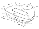
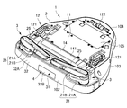
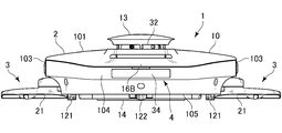
- the perspective view which looked at the self-propelled vacuum cleaner concerning one embodiment of the present invention from the upper part A perspective view of the self-propelled cleaner as viewed from below
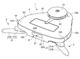
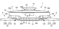
- the perspective view which looked at the projection state of the circumference cleaning means in the above-mentioned self-propelled cleaner from the upper part The perspective view which looked at the projection state of the circumference cleaning means in the above-mentioned self-propelled cleaner from the bottom Front view showing a projecting state of the surrounding cleaning means in the self-propelled cleaner
- Rear view showing the projecting state of the surrounding cleaning means in the self-propelled cleaner
- FIG. 1 is a perspective view of a self-propelled cleaner according to an embodiment of the present invention as viewed from above
- FIG. 2 is a perspective view of the self-propelled cleaner as viewed from below
- FIG. 3 is a perspective view of the protruding state of the surrounding cleaning means in the self-propelled cleaner as viewed from above
- FIG. 4 is a perspective view of the protruding state of the surrounding cleaning means in the self-propelled cleaner as viewed from below is there.
- 5 to 7 are a front view, a right side view and a rear view showing a projecting state of the surrounding cleaning means in the self-propelled cleaner.
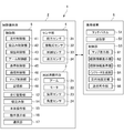
- FIG. 8 is a functional block diagram showing a schematic configuration of the self-propelled cleaner
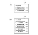
- FIGS. 9 (A) and 9 (B) are block diagrams showing part of control means of the self-propelled cleaner.
- the self-propelled cleaner 1 processes the information transmitted from the cleaner body 2, which is a cleaning robot that cleans the floor surface while traveling along the floor surface, and the information transmitted from the cleaner body 2.
- a portable terminal 6 as an information processing apparatus.
- the vacuum cleaner body 2 is, as shown in FIGS. 1 to 8, a surrounding cleaning means 3 for cleaning the periphery of the vacuum cleaner body 2, and various sensors for detecting an object around the vacuum cleaner body 2.
- a control unit 5 (see FIG. 8) as a control unit that drives and controls the cleaner body 2, the surrounding cleaning unit 3, and the sensor unit 4.
- the vacuum cleaner main body 2 carries out cleaning while traveling autonomously on the basis of the map for each space to be cleaned and the traveling schedule stored in the control unit 5.
- the vacuum cleaner body 2 includes a body 10 and a chassis 11 as shown in FIGS. 1 to 7, and the body 10 allows the upper surface portion 101, the left and right side surface portions 103, and the back surface portion 104 of the self-propelled cleaner 1.
- the bottom surface portion 105 is configured by the chassis 11.
- the sensor unit 4 includes a contact sensor 32 having a bumper 32A, and the front surface 102 of the cleaner body 2 is configured by the front surface of the bumper 32A.
- the cleaner body 2 is provided so as to be movable upward and downward from the upper surface portion 101 of the body 10 and the traveling drive portion 12 having a pair of left and right wheels 121 for self-traveling.
- Lifting portion 13 suction portion 14 provided on bottom surface portion 105 of body 10 for sucking dust and dirt on the floor surface
- main body operation portion 15 for operating cleaner body 2 and cleaner body 2
- An operation display unit 16 which is a main body indicator indicating an operation state, and a communication unit 17 for communicating with the portable terminal 6 are provided.
- the main body operation unit 15 is, for example, a touch sensor type switch (not shown) provided on the upper surface portion 101 of the vacuum cleaner main body 2 and operates the vacuum cleaner main body 2 by a touch operation by the user. The cleaner body 2 is stopped by the touch operation.
- the surrounding cleaning means 3 is provided as a left-right pair at the front of the vacuum cleaner main body 2, and an arm 21 which can be pivoted to project laterally from the cleaner main body 2, a motor 22 for rotationally driving the arm 21, and a motor
- a load sensor 23 detects a load acting from the outside 22 from the outside
- an angle sensor 24 detects a rotation angle of the arm 21.
- the arm 21 of the peripheral cleaning means 3 includes a first arm 21A rotatably supported at one end by the cleaner body 2 and a second arm 21B rotatably supported at the other end of the first arm 21A. It is configured to have.
- the first arm 21A is formed in a hollow shape as a whole, and one end side of the first arm 21A is rotatably supported by the chassis 11.
- the second arm 21B is formed in the shape of a long rod that opens downward, and its middle portion is rotatably supported on the other end side of the first arm 21A.
- the second arm 21B has a sub suction port 25 which opens downward and sucks dust and the like on the floor surface, and the sub suction port 25 is a duct of the suction portion 14 through the internal space of the second arm 21B and the first arm 21A. And the dust collection chamber.
- the sensor unit 4 includes a front sensor 31 and a contact sensor 32 provided on the front of the cleaner body 2, a surrounding sensor 33 provided on the elevating unit 13, and a rear sensor provided on the back portion 104 of the body 10. And 34 are configured.
- the front sensor 31 is a 3D sensor such as a depth camera or 3D-LIDAR, and a light emitting unit (not shown) for emitting light such as infrared light or laser light forward, and the emitted light is reflected back to the object And a light receiving unit (not shown) for receiving the reflected light, which is covered by the acrylic plate 32B of the bumper 32A.
- the light receiving unit is constituted by an image sensor such as a CMOS or a CCD in which a plurality of light receiving elements are arranged in a grid (matrix), and is on a two-dimensional plane along a vertical plane orthogonal to the front and back direction of the cleaner body 2 Reflected light is received by a plurality of light receiving elements (measurement points).
- the front sensor 31 measures the distance to the object for each light receiving element based on the time from the light emission from the light emitting part to the reception of the reflected light reflected by the object by each light receiving element of the light receiving part. By detecting, an object present in front of the cleaner body 2 is detected three-dimensionally.
- the contact type sensor 32 is provided with a bumper 32A supported so as to be movable in the front, rear, left, and right relative to the body 10 at the front of the cleaner body 2. Inside the bumper 32A, a support (not shown) for supporting the bumper 32A movably back and forth and right and left with respect to the body 10, and a sensor for detecting that the bumper 32A has moved backward and left and right with respect to the body 10. A portion (not shown) and a biasing portion (not shown) for biasing the bumper 32A to the initial position are provided.
- Such a contact type sensor 32 detects that the cleaner body 2 collides with an obstacle when the sensor unit detects that the bumper 32A has moved backward or to the left or right.
- the surrounding sensor 33 is a laser scanner (LIDAR (Light Detection and Ranging or Laser Imaging Detection and Ranging)) which is rotationally driven inside the elevation unit 13 and measures a distance by irradiating a laser beam such as an infrared laser. The distance to the obstacle and the shape of the obstacle are calculated.
- the surrounding sensor 33 is not limited to the one provided to the elevating unit 13, and may be provided at an arbitrary position of the body 10.
- the rear sensor 34 is for detecting a distance and a position with respect to a charging station or the like (not shown), and communicates with the charging station or the like by infrared rays or the like.
- the traveling drive unit 12 includes a pair of left and right wheels 121, and a motor (not shown) that rotationally drives the pair of wheels 121 independently.
- an auxiliary wheel 122 is provided at the rear of the chassis 11.
- the roller brush 141, a duct (not shown), a suction fan, a dust collection chamber, and an exhaust port are connected to the suction portion 14, and the suctioned dust is collected by the filter of the dust collection chamber and the sucked air is exhausted. It is designed to exhaust from the mouth.
- a sub duct as a dust collection path communicated with the arm 21 of the surrounding cleaning means 3 is connected to the duct or dust collection chamber of the suction portion 14.
- the operation display unit 16 includes a pair of left and right blinkers 16A provided across the front surface portion 102 and the left and right side surface portions 103 in the vicinity of the upper surface portion 101 of the body 10, and a backlight 16B provided on the back surface portion 104. Equipped with The blinker 16A incorporates a light emitting means such as an LED or the like, and when the cleaner body 2 turns to the right or to the left during self-running, the blinker 16A on the right or the left blinks to indicate the turning operation.
- the backlight 16B incorporates a light emitting means such as an LED, and blinks when the cleaner body 2 retreats to indicate a retreating operation.
- the operation display unit 16 may include not only the blinkers 16A and the backlight 16B, but also light emitting means such as a plurality of LEDs arranged around the body 10, corresponding to the traveling direction of the cleaner body 2 By turning on or blinking the light emitting means at the position, it may be possible to display an arbitrary traveling direction such as front / rear / left / right or oblique direction. Furthermore, the operation display unit 16 is configured to include various main body indicators indicating various operating conditions of the vacuum cleaner main body 2 other than those indicating the advancing direction of the vacuum cleaner main body 2 such as the blinkers 16A and the backlight 16B. May be
- the communication unit 17 performs bidirectional communication between the cleaner body 2 and the portable terminal 6 by various wireless communication methods such as Wi-Fi (Wireless Fidelity (registered trademark), Bluetooth (registered trademark), infrared communication, etc. And an antenna, an infrared light emitting unit, etc. not shown.
- the communication unit 17 may directly communicate with the mobile terminal 6 by radio waves or infrared rays of a predetermined frequency, or a network line such as a local area network (LAN) or a wide area network (WAN), a mobile phone, etc.
- the mobile terminal 6 may communicate with the mobile terminal 6 via a wireless or wired telephone network used for
- the control unit 5 includes a travel control unit 41 that controls the travel drive unit 12, a suction control unit 42 that controls the suction unit 14, a front sensor 31 of the sensor unit 4, a contact sensor 32, a surrounding sensor 33, and a rear sensor 34. And a detection control unit 43 that processes detection signals from the load sensor 23 and the angle sensor 24 of the surrounding cleaning unit 3, and an arm control unit 44 that drives and controls the motor 22 of the surrounding cleaning unit 3 to rotate the arm 21; Equipped with Furthermore, the control unit 5 controls the operation display unit 16 to cause the blinker 16A and the backlight 16B to blink, and the communication control unit 46 to control the communication unit 17 to execute communication with the portable terminal 6.
- a map control unit 47 for creating or correcting a map of a space to be cleaned, a travel route, and a travel schedule
- a storage unit (memory) 48 for storing various information such as the map, route information, and travel schedule. , Is configured.
- the detection control unit 43 acquires an ambient information acquiring unit (ambient information acquiring unit) 431 that acquires ambient information on an object in the space to be cleaned based on a detection signal from the sensor unit 4. And a position information acquisition unit (position information acquisition unit) 432 for acquiring position information of the cleaner body 2 in the space to be cleaned.
- the position information acquisition unit 432 may use a technology (e.g., SLAM (Simultaneous Localization and Mapping) technology or the like) to estimate its own position based on the driving amount of the traveling drive unit 12 or based on ambient information. Get information.
- SLAM Simultaneous Localization and Mapping
- cleaning target spaces such as living rooms and corridors
- fixed objects such as doors, furniture and household appliances installed in cleaning target spaces
- installation objects such as rugs
- cleaning targets It is a non-fixed item such as daily necessities and clothes, footwear, and toys placed on the floor of the space. Since the fixed object does not move, it becomes a standard for defining the map of the space to be cleaned and the travel route. Although the installation does not usually move, the position may be changed due to new construction, disposal, re-modification, etc., which may become an obstacle at the time of cleaning.
- the non-fixed matter is non-stationary in the presence or absence, and is likely to be an obstacle during cleaning.
- the ambient information acquired by the ambient information acquiring unit 431 relates to objects such as fixed objects, installed objects, non-fixed objects, etc., and planar position information in the space to be cleaned and three-dimensional shape information of the objects.
- a map of the space to be cleaned is generated, and a travel schedule based on the map of the space to be cleaned is generated, and these are stored in the storage unit 48.
- the traveling schedule is a cleaning mode corresponding to the map, for example, cleaning using the suction portion 14 and / or the peripheral cleaning means 3 or cleaning the same portion repeatedly, cleaning the suction portion 14 and the peripheral cleaning
- the setting value which takes place or time, such as changing the suction strength of the means 3 or changing the traveling speed by the traveling drive unit 12, is defined.
- the map control unit 47 generates a map of the space to be cleaned based on the surrounding information and the position information acquired by the detection control unit 43, the surrounding information and the position information.
- the route information creation unit 472 creates route information on the traveling route of the cleaner body 2 based on the above, and the cleaning information on the result of cleaning the cleaner body 2 based on the route information created by the route information generation unit 472 And a cleaning information creation unit 473 to be created. Further, the map control unit 47 determines whether to correct the map based on the previously created map and the newly obtained surrounding information and position information, and the correction determination unit 474, the correction determination unit 474, and the like.
- a correction execution unit 475 that corrects a map, route information, and cleaning information created last time based on the newly acquired ambient information and position information when it is determined that correction is to be performed.
- the map generation unit 471 when the map generation unit 471 generates a map for the new space to be cleaned, the map generation unit 471 updates the map with respect to the known space to be cleaned for which the map has already been generated.
- the map update mode in the case of an autonomous cleaning mode in which normal autonomous cleaning is performed on a known space to be cleaned, in the case of a space determination mode in which appropriate things are determined from a plurality of known spaces to be cleaned .
- cleaning may be performed by driving the suction portion 14 and the surrounding cleaning means 3 or without driving the suction portion 14 and the surrounding cleaning means 3. It is also good.
- the mobile terminal 6 is a mobile communication device that is portable and has a communication function such as a mobile phone, a smartphone, a tablet terminal, a notebook computer, a PDA, a smart watch, etc., and as shown in FIG.
- a touch panel 51, a communication unit 52, and a control unit 53 are provided.
- the touch panel 51 is a liquid crystal display that can receive an operation input from the user
- the communication unit 52 is an interface that can communicate by the same wireless communication method as the communication unit 17 of the cleaner body 2.
- the cleaner body 2 and the portable terminal 6 can communicate bi-directionally via the communication units 17 and 52 of each other, and the map created by the map creation unit 471 of the cleaner body 2 and the route information creation unit 472
- the portable terminal 6 can receive various information such as created route information, cleaning information and cleaning range information created by the cleaning information creation unit 473, and the cleaner body 2 can receive an operation command from the portable terminal 6 There is.
- the control unit 53 includes an operation unit such as a CPU (not shown) and a storage unit such as a ROM and a RAM to control the operation of the mobile terminal 6 and is configured to be able to execute application software linked with the cleaner body 2 It is done.
- the control unit 53 causes the map display unit 61 to display the map received from the cleaner body 2 on the touch panel 51, the route information display unit 62 to display route information on the touch panel 51 by overlapping the map, and cleaning by overlapping the map. And a cleaning information display unit 63 for displaying information on the touch panel 51.
- control unit 53 superimposes the image of the cleaner body on the map and displays the map on the touch panel 51, and an indicator generation unit 64 for adding an indicator indicating the operation status of the cleaner body 2 to this image;
- a destination setting unit 65 that sets a destination in the map by receiving an operation input to the touch panel 51; and
- a transmission command unit 66 that transmits a movement command for moving the vehicle toward the destination to the cleaner body 2; Equipped with
- FIG. 10 is a flow chart showing the operation of the cleaner body in the self-propelled cleaner.
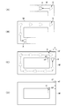
- FIG. 11 is a diagram for explaining how the self-propelled cleaner creates a map.
- the cleaner body 2 acquires surrounding information and position information as shown in FIG. 10 (ambient information Position information acquisition process: step ST1).
- the distance to the surrounding object is three-dimensionally detected by the front sensor 31 and the environment sensor 33, and the environment information acquiring unit 431 sequentially detects the distance to the object It stores in the storage unit 48, and generates ambient information on an object such as a fixed object, an installed object, or a non-fixed object in the space to be cleaned.
- the ambient information acquiring unit 431 recognizes that an object is present at the position, stores the position in the storage unit 48, and generates ambient information. Furthermore, in the ambient information / position information acquisition step, the position of the cleaner body 2 in the space to be cleaned is detected based on the drive amount of the traveling drive unit 12, and the position information acquisition unit 432 generates position information.
- the map creating unit 471 of the map control unit 47 creates a map of the space to be cleaned based on the surrounding information and the position information (map creating step: step ST2). Specifically, the surrounding information and the position acquired by repeating detection and storage of the object by the front sensor 31, the contact sensor 32, and the surrounding sensor 33 while the cleaner body 2 is self-propelled by the traveling drive unit 12 Based on the information, the map creating unit 471 identifies relative positions and shapes of fixed objects, installed objects, non-fixed objects and the like in the space to be cleaned, and the relative positions and shapes of these as planar or three-dimensional map information. The constructed and constructed map information is stored in the storage unit 48 as a map.
- the map of the space to be cleaned thus generated includes a floor surface, a wall surface rising from the floor surface, a surface of furniture etc. rising continuously from the floor surface, a step on the floor surface, a protrusion protruding from the floor surface or the wall surface, It includes the shape of an object such as the side or bottom of furniture or the like which is spaced upward from the floor surface.
- the control unit 5 generates a traveling schedule for efficiently cleaning the entire space to be cleaned, and stores the travel schedule in the storage unit 48.
- the map creating unit 471 creates the map M sequentially in real time as the cleaner body 2 travels.
- FIG. 11 conceptually shows the arithmetic processing by the control unit 5, and the cleaner body 2 itself is recognized as a virtual cleaner body A.
- the map generation unit 471 changes the distance to the target object detected by the front sensor 31 and the surrounding sensor 33 and the shape of the target (surrounding information, position information) as shown in FIG.
- a partial map M around the cleaner body A is created in real time.
- the map creating unit 471 as shown in FIG. Consecutive objects are connected to draw the shape of the object, and the map M is sequentially enlarged and created.
- the route information creation unit 472 of the map control unit 47 creates route information related to the travel route of the cleaner body 2 based on the newly acquired surrounding information and position information (route information creation step: step ST3). Specifically, the route information creation unit 472 executes an operation to sequentially continue the position information obtained based on the drive amount of the traveling drive unit 12 so that the route of the cleaner body 2 in the space to be cleaned is The route information indicating whether the vehicle has traveled is created, and the route information is stored in the storage unit 48.
- the cleaning information creation unit 473 of the map control unit 47 creates cleaning information on the result of cleaning by the cleaner body 2 based on the route information created by the route information creation unit 472 (cleaning information creation process: Step ST4). Specifically, the cleaning information creation unit 473 associates the drive state of the cleaner body 2 with each position on the travel route in the route information, and creates cleaning information indicating where in the travel route the cleaning has been performed.
- the cleaning information is stored in the storage unit 48.
- the cleaning information includes cleaning range information on a range cleaned by the cleaner body 2, dust information indicating the amount of rubbed-in dust, stack information indicating that the cleaner body 2 is stacked while traveling, etc. include.
- the cleaning information creation unit 473 creates cleaning range information on the range cleaned by the cleaner body 2 based on the execution information on the execution state of the cleaning by the cleaner body 2 and the route information (cleaning range information creating process Step ST5). Specifically, the cleaning information generation unit 473 associates the driving states of the suction portion 14 of the cleaner body 2 and the surrounding cleaning means 3 with each position on the traveling route in the route information, and performs cleaning in the traveling route. Cleaning range information indicating whether it has been executed is created, and the cleaning range information is stored in the storage unit 48.
- the execution information of the cleaning by the cleaner body 2 as the execution state of the cleaning by the suction unit 14 and the surrounding cleaning means 3, for example, vacuum ON / OFF, suction intensity change, repeated cleaning of the same place The number is included.
- the correction determination unit 474 of the map generation unit 471 determines whether to correct the map M based on the previously generated map and the newly obtained surrounding information and position information (map comparison step: step ST6) ). Specifically, the correction determination unit 474 calculates a two-dimensional or three-dimensional relative distance as a positional error of the newly acquired surrounding information and position information with respect to the map M created last time. Furthermore, the correction determination unit 474 determines whether the calculated error is larger than a predetermined allowable value (threshold) (error determination step: step ST7). In the error determination step (step ST7), when the error is larger than the predetermined allowable value (YES in step ST7), correction execution unit 475 corrects map M (map correction step: step ST8), and the error is predetermined. If the allowable value is not exceeded (NO in step ST7), the map correction step (step ST8) is skipped.
- a predetermined allowable value threshold
- the correction execution unit 475 corrects the map M created last time on the basis of the newly acquired ambient information and position information. Specifically, when an object present in the previous map M can not be detected, an object absent in the previous map M is detected, or the object is moved The surrounding information acquired by the surrounding information acquisition unit 431 is different from the previous map M. In addition, even when the wheel 121 of the traveling drive unit 12 is idled or the wheel 121 rides on or is caught on an obstacle, an error occurs in the position information acquired by the position information acquiring unit 432, and the surrounding information is the previous map It is different from M.
- the correction execution unit 475 constructs the relative position and the shape of the object at the location different from the previous map M as the map information each time.
- the generated map information is overwritten as the new map M on the previous map M and stored in the storage unit 48.
- the correction execution unit 475 performs the route information created in the route information creating process (step ST3), the cleaning information created in the cleaning information creating process (step ST4), and the cleaning created in the cleaning range information creating process (step ST5). The same correction is performed on the range information and stored in the storage unit 48.
- step ST6 From the map comparison step (step ST6) to the map correction step (step ST8) as described above, arithmetic processing by the control unit as shown in FIGS. 11C and 11D is executed. That is, as shown in FIG. 11C, when the vacuum cleaner main body A returns to the vicinity of the initial position S, detecting an object around the initial position S and newly acquiring surrounding information and position information, The position of the target object and the map M created at the previous time (at the initial position S) may be detected in a shifted manner. Specifically, the feature points a1 and b1 in the map M created last time may not match the feature points a2 and b2 based on the newly acquired surrounding information and position information.
- the correction determination unit 474 calculates the amount of positional deviation between the feature points a1 and b1 and the feature points a2 and b2 as the error e.
- the correction determination unit 474 compares the error e with the tolerance, and if the error e is larger than the tolerance, the correction execution unit 475 in FIG. 11 performs the map correction step (step ST8). As shown in (D), the map M is corrected with the feature points a2 and b2 based on the newly acquired ambient information and position information as correct positions.
- the correction execution unit 475 also corrects the route information, the cleaning information, and the cleaning range information. That is, before correction, the route information, the cleaning information, and the cleaning range information are created based on the position (coordinates) corresponding to the map M created last time, and are sequentially stored in the storage unit 48. Therefore, by executing the same correction as that for the map M, the positions of the route information, the cleaning information, and the cleaning range information correspond to the map M after the (coordinates) correction.
- the control unit 5 determines whether or not cleaning of the entire area of the space to be cleaned has been completed, that is, whether or not the traveling schedule for the space to be cleaned has been completed (cleaning completion determination Process: step ST9).
- cleaning completion determination Process step ST9
- the control unit 5 continues the driving of the traveling drive unit 12, the suction unit 14 and the surrounding cleaning means 3
- the cleaning end determination step step ST9 is repeatedly executed from the ambient information and position information acquisition step (step ST1).
- step ST9 when it is determined that the cleaning is ended (YES in step ST9), the control unit 5 stops the driving of the traveling drive unit 12, the suction unit 14 and the surrounding cleaning means 3. Exit the autonomous cleaning mode.
- the control unit 5 controls the ambient information acquiring unit 431 and the positional information acquiring unit 432 in the ambient information acquisition step (step ST1) during the operation of the cleaner body 2 in the autonomous cleaning mode. And each time position information is acquired, the map creation unit 471 creates a map of the space to be cleaned in real time in the map creation step (step ST2). Further, in the control unit 5, the route information creation unit 472 creates route information in the route information creation process (step ST3), and the cleaning information creation unit 473 creates the cleaning information in the cleaning information creation process (step ST4). In the range information creating process (step ST5), the cleaning information creating unit 473 creates cleaning range information.
- the control unit 5 performs the correction execution unit 475 in the map correction step (step ST8). Correct the previously created map.
- the map, route information, cleaning information and cleaning range information thus created and corrected are sequentially stored in the storage unit 48, and are transmitted to the portable terminal 6 via the communication unit 17 in response to a request from the portable terminal 6. Will be sent.
- FIGS. 12 to 14 are views showing display images of the information processing apparatus in the self-propelled cleaner, respectively.
- the control unit 53 When the portable terminal 6 receives the map, the route information, the cleaning information, and the cleaning range information from the cleaner body 2 through the communication unit 52, the control unit 53 generates the display image G based on the information and generates the generated information.
- the display image G is displayed on the touch panel 51.
- the display image G is a moving image (animation) corresponding to the operation of the cleaner body 2, and the user can confirm the operation state of the cleaner body 2 in real time by viewing the display image G.
- the display image G displayed on the touch panel 51 of the mobile terminal 6 will be described in detail.
- the display image G includes a body image B obtained by imaging the cleaner body 2, a map image M obtained by imaging the map of the space to be cleaned, and a route image R obtained by imaging the route information. And a cleaning image C obtained by imaging the cleaning information and the cleaning range information.
- the main body image B includes an indicator B1 that blinks corresponding to the operation display unit 16.
- the body image B is displayed so as to move in the display image G based on the position information acquired by the position information acquisition unit 432 of the cleaner body 2 in order to express the traveling operation of the cleaner body 2.
- the indicator B1 is display-controlled by the indicator generation unit 64, and displays an operation common to the operation status of the operation display unit 16 (for example, blink of the blinker 16A) (the indicator B1 blinks).
- the indicator B1 may be displayed superimposed on a part of the main body image B as an image imitating the operation display unit 16 of the vacuum cleaner main body 2, or may be displayed larger or smaller than the main body image B.
- the image B may be displayed at a different
- a fixed object image M1 representing a fixed object such as a wall of a space to be cleaned
- an installed object image M2 representing an installed object
- a non-fixed object image M3 representing a non-fixed object (see FIG. 13)
- An origin image M4 or the like representing an origin is included.
- the map image M is display-controlled by the map display unit 61 based on the surrounding information acquired by the surrounding information acquiring unit 431 of the vacuum cleaner main body 2, and displays the map created or updated in real time.
- the route image R is display-controlled by the route information display unit 62 based on the position information acquired by the position information acquisition unit 432 of the cleaner body 2 and displays a linear traveling route corresponding to the traveling operation of the cleaner body 2 It is
- the cleaning image C is displayed and controlled by the cleaning information display unit 63 based on the cleaning information and the cleaning range information created by the cleaning information creation unit 473 of the cleaner body 2, and the strip cleaning corresponding to the cleaning operation of the cleaner body 2 is performed.
- the range is displayed.
- This cleaning image C is displayed in the place where the cleaner body 2 is performing cleaning, and not displayed in the place where the traveling is not performing the cleaning, and the execution and non-execution of the cleaning by the place are used Can be determined from the Further, the cleaning image C is color-coded and displayed according to the execution state of the cleaning by the cleaner body 2 so that the execution state of the cleaning by the place can be determined from the user.
- the map image M, the route image R, and the cleaning image C generated along with the cleaning operation of the cleaner body 2 are newly generated and displayed each time the cleaning is performed. That is, when the object in the space to be cleaned changes or the traveling operation or cleaning operation of the cleaner body 2 changes, as shown in FIG. 13, the map image M, the route image R, and the cleaning image C It is displayed in a state different from that of the previous one (display image G shown in FIG. 12). Specifically, when there is a non-fixed object that did not exist at the time of the previous cleaning, the non-fixed object showing the non-fixed object is detected because the non-fixed object is detected and the surrounding information and the map are updated. A display image G including M3 is displayed. Furthermore, since the cleaner body 2 travels and cleaning is performed avoiding the non-fixed object, the route image R and the cleaning image C around the non-fixed object image M3 are also displayed as different from the previous time.
- the surrounding information and the map are updated without detecting the installation, so the display image G without the image M2a is displayed where the installation was.
- the route image R and the cleaning image C at this location are also displayed as different from the previous one.
- the surrounding information and map related to the fixed object are updated, so the fixed object image M1a that was in the previous map and The fixed object image M1 is displayed at a different position, and the route image R and the cleaning image C are also displayed as different from the previous one, corresponding to the fixed object image M1.
- the creation and updating of the map is not limited to the comparison with the map created at the previous cleaning, and it is executed every time a plurality of the same place is passed even during one autonomous cleaning mode, such timing However, if the map is updated, the map image M, the route image R, and the cleaning image C are newly generated and displayed based on the updated map.
- the destination setting unit 65 of the portable terminal 6 When the destination setting unit 65 of the portable terminal 6 receives an operation input from the user (a touch operation on the touch panel 51), the destination setting unit 65 sets a destination in the map, and the transmission command unit 66 moves toward the destination.
- the movement command of is transmitted to the cleaner body 2.
- the destination setting unit 65 sets the coordinate value of this position as the destination, Lights up the place M3a.
- the transmission control unit 66 transmits the coordinates of the destination as a movement command to the cleaner body 2 via the communication unit 52.
- the control unit 5 of the cleaner body 2 receiving the movement command drives the traveling drive unit by the traveling control unit 41 to cause the cleaner body 2 to travel toward the coordinates of the destination, and cleans around the destination. Run it. Such traveling and cleaning of the cleaner body 2 to the destination is also displayed as a route image R and a cleaning image C on the portable terminal 6 in real time.
- the map creating unit 471 maps the map of the space to be cleaned including the vacuum cleaner body 2
- the map display unit 61 of the portable terminal 6 displays the map image M of the map created and the user can grasp the situation of the vacuum cleaner main body 2 in the space to be cleaned in real time. Therefore, the user can confirm whether there is a change in the environment of the space to be cleaned, the operating condition of the vacuum cleaner body 2, and whether the map of the space to be cleaned is properly created.
- the cleaning efficiency can be improved by making it coping possible.
- the correction execution unit 475 In the self-propelled vacuum cleaner 1, when the correction determination unit 474 determines that the correction is necessary for the created map, the correction execution unit 475 generates a map based on the newly acquired surrounding information and position information. Correction can improve the accuracy of the map created in real time.
- the route information creation unit 472 creates route information related to the travel route of the cleaner body 2, and the created route information is portable terminal
- the route information display unit 62 of 6 is superimposed on the map image M as the route image R and displayed, the user can confirm the traveling route of the cleaner body 2 in the space to be cleaned.
- the path information generation unit 472 corrects the path information according to the corrected map, thereby achieving consistency between the corrected map and the path information. be able to.
- the cleaning information creation unit 473 creates cleaning information on the result of cleaning by the cleaner body 2 based on the route information, and the cleaning information display unit of the mobile terminal 6 creates the cleaning information By displaying 63 as the cleaning image C superimposed on the map image M, the user can confirm the result of cleaning by the cleaner body 2 in the space to be cleaned. Furthermore, when the map is corrected by the correction execution unit 475, the cleaning information generation unit 473 corrects the cleaning information according to the corrected map, thereby achieving consistency between the corrected map and the cleaning information. The user can accurately grasp the cleaned place.
- the cleaning information creation unit 473 creates cleaning range information based on the cleaning execution information and the route information, and the cleaning information display unit 63 overlaps the map image M with the cleaning range information as the cleaning image C.
- the user can confirm in real time the execution state of cleaning by the vacuum cleaner body 2 (vacuum ON / OFF, suction intensity change, the number of times of cleaning of the same place, etc.) and the range cleaned. Can.
- the portable terminal 6 includes the destination setting unit 65 and the transmission control unit 66, and transmits the destination input by the user to the cleaner body 2.
- the cleaner body 2 is based on the received movement command. By moving toward the destination in the space to be cleaned, the cleaner body 2 can be moved to an arbitrary place in the space to be cleaned according to the user's request, and the cleaning can be performed. Therefore, for example, even if the surroundings of the obstacle in the space to be cleaned can not be cleaned, the user removes the obstacle and then moves the cleaner body 2 to the place as the destination. While being able to clean the place where the obstacle was, the map after removing the obstacle can be created.
- the portable terminal 6 includes the indicator generation unit 64, and the indicator generation unit 64 superimposes the indicator B1 indicating the action status of the vacuum cleaner main body 2 on the main image B in the map image M and displays it.
- the indicator B1 indicates the common operation status as an image imitating the operation display unit 16 of the cleaner body 2 so that the user can intuitively clean as compared with the case where the indicator is displayed as character information, etc. The operating condition of the machine body 2 can be grasped.
- the present invention is not limited to the above-described embodiment, and modifications, improvements, and the like as long as the object of the present invention can be achieved are included in the present invention.
- the map control unit 47 including the map generation unit 471 is provided in the control unit 5 of the cleaner main body 2, but the map is displayed on the portable terminal (information processing device) 6 A control unit may be provided.
- the surrounding information acquiring unit 431 and the position information acquiring unit 432 provided in the control unit 5 of the cleaner body 2 acquire the surrounding information and the position information, and transmit the surrounding information and the position information to the information processing apparatus
- the map control unit of the information processing apparatus may create a map, update the map, or create route information, cleaning information, and cleaning range information.
- the map control unit 47 of the embodiment includes the map generation unit 471, the route information generation unit 472, the cleaning information generation unit 473, the correction determination unit 474, and the correction execution unit 475, but at least only the map generation unit.
- the route information creation unit, the cleaning information creation unit, the correction determination unit, and the correction execution unit can be omitted as appropriate.
- at least only the map display unit among the map display unit 61, the route information display unit 62, and the cleaning information display unit 63 may be provided, and the route information display unit and the cleaning information display unit It can be omitted as appropriate.
- the information processing apparatus is a mobile communication apparatus such as a mobile phone, a smart phone, or a tablet terminal.
- the information processing apparatus is not limited thereto, and is installed in a desktop personal computer, a house or a car as an information processing apparatus. It may be a terminal device, a display device such as a television, or the like.
- the function of the map control unit 47 including the map creating unit 471 may be realized by a server apparatus on the Internet.
- operation input is not only this but arbitrary input, such as a keyboard, a mouse, and a track pad. It may be performed by the device.
- the portable terminal (information processing apparatus) 6 includes an indicator generation unit 64, and the indicator generation unit 64 superimposes an indicator B1 indicating the action status of the cleaner main body 2 on the main image B in the map image M. Although displayed, such an indicator may not be displayed.
- the portable terminal (information processing apparatus) 6 includes the destination setting unit 65 and the transmission control unit 66, the destination input by the user is transmitted to the cleaner body 2, but the destination setting is performed. Departments and transmission headquarters may be omitted.
- the ambient information acquiring unit 431 in the autonomous cleaning mode, the ambient information acquiring unit 431 generates ambient information, and the positional information acquiring unit 432 generates positional information, based on the detection of the front sensor 31, the contact sensor 32, and the ambient sensor 33.
- the map is created based on these pieces of information, ambient information and position information are acquired based on detection of any one of the front sensor 31, the contact sensor 32, and the ambient sensor 33. It may be.
- map generation mode, map update mode, and space determination mode may be sufficient.
- the correction determination unit 474 compares the error e with the tolerance in the error determination step (step ST7), and if the error e is larger than the tolerance, the correction execution unit in the map correction step (step ST8) Although 475 corrects the map M, it may be determined whether the map M is corrected, not only the error e, but also the moving distance of the cleaner body 2 from the start of cleaning. Other operation records may be included in the determination condition.
- the present invention can be suitably used for a self-propelled cleaner that allows the user to confirm the operation status of the cleaner body and the map created and can improve the cleaning efficiency.
Landscapes
- Engineering & Computer Science (AREA)
- Mechanical Engineering (AREA)
- Radar, Positioning & Navigation (AREA)
- Aviation & Aerospace Engineering (AREA)
- Remote Sensing (AREA)
- Physics & Mathematics (AREA)
- General Physics & Mathematics (AREA)
- Automation & Control Theory (AREA)
- Electric Vacuum Cleaner (AREA)
- Control Of Position, Course, Altitude, Or Attitude Of Moving Bodies (AREA)
Abstract
【課題】掃除機本体の動作状況や作成されるマップを使用者が確認することができ、清掃効率を向上させることができる自走式掃除機を提供。 【解決手段】自走式掃除機(1)は、掃除機本体(2)と携帯端末(6)とを備える。掃除機本体(2)が自走しつつ周囲情報および位置情報を取得する都度、マップ作成部(471)が掃除機本体(2)を含む清掃対象空間のマップをリアルタイムで作成するとともに、携帯端末(6)のマップ表示部(61)がマップを表示する。
Description
本発明は、自走式掃除機に関する。
従来、清掃対象空間の床面を清掃するための自走式掃除機(掃除ロボット)として、対象物(例えば、壁や家具など)の位置や大きさ、形状を測定して清掃対象空間のマップ(地図情報)を作成するとともに、このマップに応じた走行経路および走行スケジュールを設定し、走行経路および走行スケジュールに従って清掃対象空間の掃除を行うものが知られている(例えば、特許文献1等参照)。特許文献1に記載された自走式掃除機は、地図情報作成手段と地図情報記憶手段とを備え、掃除動作の開始と同時に地図情報の作成を開始するとともに、掃除動作中に走行する距離に応じて地図情報を更新して地図情報記憶手段に記憶させ、更新した最新の地図情報を参照して未掃除領域を検索し、未掃除領域に対して掃除動作を実行するように構成されている。
しかしながら、特許文献1に記載されたような従来の自走式掃除機では、清掃対象空間のマップを作成するとともに掃除動作中にマップを更新し、更新したマップに基づいて未掃除領域に対する掃除動作を実行するものの、作成あるいは更新されるマップがどのようなものになっているかが使用者から判別できない。このため、清掃対象空間において家具の位置が変更されたり、日用品や衣服などが一時的に置かれたりした場合、マップが適切に作成、更新されているかどうかを使用者が確認することができず、不適切なマップが作成されてしまう事態を回避することができず、その結果として清掃効率が悪化してしまう可能性がある。
本発明の目的は、掃除機本体の動作状況や作成されるマップを使用者が確認することができ、清掃効率を向上させることができる自走式掃除機を提供することである。
本発明の自走式掃除機は、床面に沿って自走しつつ床面を清掃可能な掃除機本体と、この掃除機本体から送信された情報を処理する情報処理装置と、を備えた自走式掃除機であって、前記掃除機本体は、清掃対象空間の対象物に関する周囲情報を取得する周囲情報取得手段と、清掃対象空間における当該掃除機本体の位置情報を取得する位置情報取得手段と、を備え、前記掃除機本体および前記情報処理装置の少なくとも一方は、前記周囲情報および前記位置情報に基づいて清掃対象空間のマップを作成するマップ作成部を備え、前記情報処理装置は、前記マップを表示するマップ表示部を備え、前記掃除機本体が自走しつつ前記周囲情報および前記位置情報を取得する都度、前記マップ作成部が当該掃除機本体を含む前記清掃対象空間のマップをリアルタイムで作成するとともに、前記情報処理装置のマップ表示部がマップを表示することを特徴とする。
このような本発明によれば、自走式掃除機は、掃除機本体の自走に伴って取得した周囲情報および位置情報に基づき、この掃除機本体を含む清掃対象空間のマップをマップ作成部がリアルタイムで作成し、作成したマップを情報処理装置のマップ表示部が表示することで、使用者は清掃対象空間における掃除機本体の状況をリアルタイムで把握することができる。したがって、清掃対象空間の環境の変化や掃除機本体の動作状況、清掃対象空間のマップが適切に作成されているかどうかなどを使用者が確認することができ、それらに異常があった場合に対処可能とすることで、清掃効率を向上させることができる。ここで、清掃対象空間としては、居間(リビングルーム)や食堂(ダイニングルーム)、寝室、廊下など、壁等で適宜な広さに仕切られた空間が例示でき、このような清掃対象空間では、家具や電化製品、設備器具、敷物などの設置物が設置されていることが一般的であり、このような設置物の設置状態に応じて適切なマップが作成されることで、清掃効率を高めることができる。
本発明では、前記マップ作成部は、前回作成したマップと、新たに取得した周囲情報および位置情報と、に基づいてマップを補正するか否かを判定する補正判定部と、前記補正判定部にてマップを補正すると判定した場合に、新たに取得した前記周囲情報および前記位置情報に基づいて前回作成した前記マップを補正する補正実行部と、を備えることが好ましい。
このような構成によれば、マップ作成部が補正判定部と補正実行部とを備え、補正判定部によって補正が必要と判定された場合に、新たに取得した周囲情報および位置情報に基づいて補正実行部がマップを補正することで、リアルタイムで作成するマップの精度を向上させることができる。
本発明では、前記掃除機本体および前記情報処理装置の少なくとも一方は、新たに取得した周囲情報および位置情報に基づき、前記掃除機本体の走行経路に関する経路情報を作成する経路情報作成部を備え、前記情報処理装置は、前記経路情報を前記マップに重ねて表示する経路情報表示部を備え、前記経路情報作成部は、前記補正実行部にてマップを補正した場合に、補正後のマップに応じて経路情報を補正することが好ましい。
このような構成によれば、自走式掃除機は、新たに取得した周囲情報および位置情報に基づき、掃除機本体の走行経路に関する経路情報を経路情報作成部が作成し、作成した経路情報を情報処理装置の経路情報表示部がマップに重ねて表示することで、使用者は清掃対象空間における掃除機本体の走行経路を確認することができる。さらに、補正実行部にてマップを補正した場合に、経路情報作成部は、補正後のマップに応じて経路情報を補正することで、補正後のマップと経路情報との整合性をとることができる。
本発明では、前記掃除機本体および前記情報処理装置の少なくとも一方は、前記経路情報作成部にて作成された経路情報に基づき、前記掃除機本体が掃除した結果に関する掃除情報を作成する掃除情報作成部を備え、前記情報処理装置は、前記掃除情報を前記マップに重ねて表示する掃除情報表示部を備え、前記掃除情報作成部は、前記補正実行部にてマップを補正した場合に、補正後のマップに応じて掃除情報を補正することが好ましい。
このような構成によれば、自走式掃除機は、経路情報に基づき、掃除機本体が掃除した結果に関する掃除情報を掃除情報作成部が作成し、作成した掃除情報を情報処理装置の掃除情報表示部がマップに重ねて表示することで、使用者は清掃対象空間における掃除機本体が掃除した結果を確認することができる。ここで、掃除情報には、掃除機本体にて掃除した範囲に関する掃除範囲情報や、吸い込んだゴミの量を示すゴミ情報、掃除機本体が走行中にスタックしたことを示すスタック情報などが含まれている。さらに、補正実行部にてマップを補正した場合に、掃除情報作成部は、補正後のマップに応じて掃除情報を補正することで、補正後のマップと掃除情報との整合性をとることができ、掃除された場所を使用者が正確に把握することができる。
本発明では、前記掃除情報作成部は、前記掃除機本体による掃除の実行状態に関する実行情報と、前記経路情報作成部にて作成された経路情報と、に基づき、前記掃除機本体にて掃除した範囲に関する掃除範囲情報を作成し、前記掃除情報表示部は、前記掃除範囲情報を前記マップに重ねて表示することが好ましい。
このような構成によれば、掃除情報作成部は、掃除の実行情報と経路情報とに基づいて掃除範囲情報を作成し、掃除情報表示部は、掃除範囲情報をマップに重ねて表示することで、使用者は掃除機本体による掃除の実行状態と掃除した範囲をリアルタイムで確認することができる。ここで、実行情報には、掃除機本体による掃除の実行状態として、例えば、バキュームのON/OFFや、吸引の強度変化、同一場所の掃除の繰り返し回数などが含まれている。
本発明では、前記情報処理装置は、使用者の操作入力を受け付けることによって前記マップ中に目的地を設定する目的地設定部と、前記目的地に向かって移動させるための移動指令を前記掃除機本体に送信する送信司令部と、を備え、前記掃除機本体は、前記情報処理装置から受信した移動指令に基づき、前記マップ中の目的地に対応した清掃対象空間中の目的地に向かって移動することが好ましい。
このような構成によれば、情報処理装置は、目的地設定部と送信司令部とを備え、使用者が入力した目的地を掃除機本体に送信し、掃除機本体は、受信した移動指令に基づいて清掃対象空間中の目的地に向かって移動することで、使用者の要求に応じて清掃対象空間中の任意の場所に掃除機本体を移動させて掃除を実行させることができる。したがって、例えば、清掃対象空間にある障害物の周囲が清掃できなかった場合であっても、使用者が障害物を除去してからその場所を目的地として掃除機本体を移動させることで、障害物のあった場所を掃除することができるとともに、障害物を除去した後のマップを作成することができる。
本発明では、前記情報処理装置は、前記掃除機本体の動作状況を示すインジケータを前記マップに表示された掃除機本体の画像に重ねて付与するインジケータ生成部を備えることが好ましい。
このような構成によれば、情報処理装置は、インジケータ生成部を備え、このインジケータ生成部が掃除機本体の行動状況を示すインジケータをマップ中の掃除機本体の画像に重ねて表示することで、使用者は、マップ中の掃除機本体の画像を見ることで実際の掃除機本体の動作状況を容易に確認することができる。
本発明では、前記掃除機本体は、当該掃除機本体の動作状況を示す本体インジケータを備え、前記本体インジケータと、前記マップに表示された掃除機本体の画像に重なるインジケータと、が共通の動作状況を示すことが好ましい。
このような構成によれば、掃除機本体の本体インジケータとマップに表示された掃除機本体の画像に重なるインジケータとが共通の動作状況を示すことで、使用者は、本体インジケータおよび情報処理装置に表示されるマップ中の掃除機本体の画像のいずれかを見ることにより、掃除機本体の動作状況を容易に確認することができる。また、マップ中の掃除機本体の画像に重ねて表示されるインジケータが、本体インジケータを模した画像として共通の動作状況を示すことで、インジケータを文字情報として表示する場合と比較して、使用者が直感的に動作状況を把握することができる。
以下、本発明の一実施形態を図1~図14に基づいて説明する。
図1は、本発明の一実施形態に係る自走式掃除機を上方から見た斜視図であり、図2は、自走式掃除機を下方から見た斜視図である。図3は、自走式掃除機における周囲清掃手段の突出状態を上方から見た斜視図であり、図4は、自走式掃除機における周囲清掃手段の突出状態を下方から見た斜視図である。図5~図7は、自走式掃除機における周囲清掃手段の突出状態を示す正面図、右側面図、背面図である。図8は、自走式掃除機の概略構成を示す機能ブロック図であり、図9(A),(B)は、自走式掃除機の制御手段の一部を示すブロック図である。
図1は、本発明の一実施形態に係る自走式掃除機を上方から見た斜視図であり、図2は、自走式掃除機を下方から見た斜視図である。図3は、自走式掃除機における周囲清掃手段の突出状態を上方から見た斜視図であり、図4は、自走式掃除機における周囲清掃手段の突出状態を下方から見た斜視図である。図5~図7は、自走式掃除機における周囲清掃手段の突出状態を示す正面図、右側面図、背面図である。図8は、自走式掃除機の概略構成を示す機能ブロック図であり、図9(A),(B)は、自走式掃除機の制御手段の一部を示すブロック図である。
自走式掃除機1は、図8に示すように、床面に沿って走行しつつ床面を清掃する掃除ロボットである掃除機本体2と、この掃除機本体2から送信された情報を処理する情報処理装置としての携帯端末6と、を備える。掃除機本体2は、図1~図8に示すように、掃除機本体2の周囲を清掃するための周囲清掃手段3と、掃除機本体2の周囲の対象物を検知するための各種のセンサからなるセンサ部4と、掃除機本体2、周囲清掃手段3およびセンサ部4を駆動制御する制御手段としての制御部5(図8参照)と、を備えている。この掃除機本体2は、制御部5に記憶された清掃対象空間ごとのマップや走行スケジュールに基づいて、自律走行しつつ清掃を実施するものである。
掃除機本体2は、図1~図7に示すように、ボディ10と、シャーシ11と、を備え、ボディ10によって自走式掃除機1の上面部101、左右の側面部103および背面部104が構成され、シャーシ11によって底面部105が構成されている。センサ部4は、バンパ32Aを有した接触式センサ32を備え、このバンパ32Aの前面によって掃除機本体2の前面部102が構成されている。
さらに、掃除機本体2は、図8にも示すように、自走するための左右一対の車輪121を有した走行駆動部12と、ボディ10の上面部101から上方に昇降自在に設けられた昇降部13と、ボディ10の底面部105に設けられて床面の塵や埃を吸い込むための吸込み部14と、掃除機本体2を操作するための本体操作部15と、掃除機本体2の動作状況を示す本体インジケータである動作表示部16と、携帯端末6と通信を行うための通信部17と、を備える。本体操作部15は、例えば、掃除機本体2の上面部101に設けられたタッチセンサ式のスイッチ(不図示)であって、使用者によるタッチ操作によって掃除機本体2を作動させ、作動中のタッチ操作によって掃除機本体2を停止させる。
周囲清掃手段3は、掃除機本体2の前部において左右一対で設けられ、掃除機本体2から側方に突出して回動可能なアーム21と、アーム21を回動駆動するモータ22と、モータ22に外部から作用する負荷を検出する負荷センサ23と、アーム21の回動角度を検出する角度センサ24と、を備える。周囲清掃手段3のアーム21は、掃除機本体2に一端側が回転自在に支持された第1アーム21Aと、第1アーム21Aの他端側に回転自在に支持された第2アーム21Bと、を有して構成されている。第1アーム21Aは、全体中空状に形成され、その一端側がシャーシ11に回転自在に支持されている。第2アーム21Bは、下方に開口した全体長尺椀状に形成され、その中間部が第1アーム21Aの他端側に回転自在に支持されている。第2アーム21Bは、下方に開口して床面の埃などを吸い込む副吸込み口25を有し、副吸込み口25は、第2アーム21Bおよび第1アーム21Aの内部空間を通して吸込み部14のダクトおよび集塵室に連通されている。
センサ部4は、掃除機本体2の前部に設けられた前方センサ31および接触式センサ32と、昇降部13に設けられた周囲センサ33と、ボディ10の背面部104に設けられた後方センサ34と、を有して構成されている。
前方センサ31は、深度カメラや3D-LIDAR等の3Dセンサであって、赤外線やレーザー光等の光を前方に出射する発光部(不図示)と、出射した光が対象物に反射して戻ってくる反射光を受光する受光部(不図示)と、を有し、バンパ32Aのアクリル板32Bに覆われている。受光部は、複数の受光素子が格子状(マトリクス状)に配置されたCMOSやCCD等のイメージセンサで構成され、掃除機本体2の前後方向に直交する鉛直面に沿った二次元平面上の複数の受光素子(測定点)で反射光を受光する。したがって、前方センサ31は、発光部から光を出射してから、対象物に反射した反射光を受光部の各受光素子で受光するまでの時間に基づき、受光素子ごとに対象物までの距離を検出することで、掃除機本体2の前方に存在する対象物を三次元的に検出する。
接触式センサ32は、掃除機本体2の前部においてボディ10に対して前後左右に移動自在に支持されたバンパ32Aを備えている。バンパ32Aの内側には、ボディ10に対してバンパ32Aを前後左右に移動自在に支持する支持部(不図示)と、ボディ10に対してバンパ32Aが後方および左右に移動したことを検知するセンサ部(不図示)と、バンパ32Aを初期位置に付勢する付勢部(不図示)と、が設けられている。このような接触式センサ32は、バンパ32Aが後方または左右に移動したことをセンサ部が検知することで、掃除機本体2が障害物に衝突したことを検出する。
周囲センサ33は、昇降部13の内部で回転駆動されるとともに、赤外線レーザー等のレーザー光を照射して距離を測定するレーザースキャナ(LIDAR(Light Detection and RangingまたはLaser Imaging Detection and Ranging))であって、障害物までの距離や障害物の形状を算出するものである。なお、周囲センサ33は、昇降部13に設けられたものに限らず、ボディ10の任意の位置に設けられていればよい。後方センサ34は、図示しない充電ステーション等に対する距離や位置を検出するためのものであって、充電ステーション等との間で赤外線等による通信を行う。
走行駆動部12は、左右一対の車輪121と、一対の車輪121を各々独立して回転駆動するモータ(不図示)と、を備えている。また、シャーシ11の後部には、補助輪122が設けられている。吸込み部14には、ローラーブラシ141、図示しないダクト、吸引ファン、集塵室および排気口が接続されており、吸い込んだ塵等を集塵室のフィルタで集塵するとともに、吸い込んだ空気を排気口から排気するようになっている。吸込み部14のダクトまたは集塵室には、周囲清掃手段3のアーム21に連通された集塵経路としての副ダクトが接続されている。
動作表示部16は、ボディ10の上面部101付近にて前面部102と左右の側面部103とに跨って設けられた左右一対のウィンカー16Aと、背面部104に設けられたバックライト16Bと、を備える。ウィンカー16Aは、LED等の発光手段を内蔵し、掃除機本体2が自走中に右または左に転回する際に、右または左のウィンカー16Aが点滅することで転回動作を示すものである。バックライト16Bは、LED等の発光手段を内蔵し、掃除機本体2が後退する際に点滅することで後退動作を示すものである。なお、動作表示部16は、ウィンカー16Aおよびバックライト16Bのみならず、ボディ10の周囲に配置された複数のLED等の発光手段を備えていてもよく、掃除機本体2の進行方向に対応した位置の発光手段を点灯または点滅させることで、前後左右や斜め方向など任意の進行方向を表示可能なものであってもよい。さらに、動作表示部16は、ウィンカー16Aおよびバックライト16Bなどの掃除機本体2の進行方向を示すもの以外に、掃除機本体2の各種の動作状況を示す様々な本体インジケータを含んで構成されていてもよい。
通信部17は、Wi-Fi(Wireless Fidelity、登録商標)やBluetooth(登録商標)、赤外線通信などの各種無線通信方式によって掃除機本体2と携帯端末6との間で双方向に通信を行うものであって、図示しないアンテナや赤外線発光部等を備えている。通信部17は、所定周波数の電波や赤外線によって直接に携帯端末6と通信を行うものであってもよいし、ローカルエリアネットワーク(LAN)や広域ネットワーク(WAN)などのネットワーク回線や、携帯電話等に用いられる無線および有線の電話回線網などを介して携帯端末6と通信を行うものであってもよい。
制御部5は、走行駆動部12を制御する走行制御部41と、吸込み部14を制御する吸込制御部42と、センサ部4の前方センサ31、接触式センサ32、周囲センサ33、後方センサ34および周囲清掃手段3の負荷センサ23、角度センサ24からの検出信号を処理する検出制御部43と、周囲清掃手段3のモータ22を駆動制御してアーム21を回動させるアーム制御部44と、を備える。さらに、制御部5は、動作表示部16を制御してウィンカー16Aおよびバックライト16Bを点滅させる表示制御部45と、通信部17を制御して携帯端末6との通信を実行させる通信制御部46と、清掃対象空間のマップや走行経路、走行スケジュールを作成したり補正したりするためのマップ制御部47と、マップや経路情報、走行スケジュール等の各種情報を記憶する記憶部(メモリ)48と、を備えて構成されている。
検出制御部43は、図9(A)に示すように、センサ部4からの検出信号に基づいて清掃対象空間の対象物に関する周囲情報を取得する周囲情報取得部(周囲情報取得手段)431と、清掃対象空間における掃除機本体2の位置情報を取得する位置情報取得部(位置情報取得手段)432と、を備える。位置情報取得部432は、走行駆動部12の駆動量に基づいたり、周囲情報に基づいたりして自己位置を推定する技術(例えば、SLAM(Simultaneous Localization and Mapping)技術など)を用いたりして位置情報を取得する。ここで、対象物としては、居室や廊下等の清掃対象空間を形成する壁面や床面、ドアなどの固定物、清掃対象空間に設置された家具や家電製品、敷物などの設置物、清掃対象空間の床面に置かれた日用品や衣服、履物、玩具などの非固定物である。固定物は、移動しないことから清掃対象空間のマップや走行経路を規定する基準となる。設置物は、通常は移動しないものの、新設や廃棄、模様替え等によって位置が変更されることがあり、清掃時の障害物となる可能性がある。非固定物は、その存在の有無が非定常的であり、清掃時の障害物となる可能性が大きいものである。
このように周囲情報取得部431が取得する周囲情報は、固定物や設置物、非固定物などの対象物に関し、清掃対象空間における平面的な位置情報と、対象物の立体的な形状情報と、を含んでいる。この周囲情報に基づき、清掃対象空間のマップが生成されるとともに、清掃対象空間のマップに基づいた走行スケジュールが生成され、これらが記憶部48に記憶される。走行スケジュールとしては、マップに応じた清掃モードであって、例えば、吸込み部14および周囲清掃手段3の両方または一方を用いて清掃したり、同一箇所を繰り返し清掃したり、吸込み部14や周囲清掃手段3の吸込み強さを変化させたり、走行駆動部12による走行速度を変化させたりなど、場所や時間にかかる設定値が定義されたものである。
マップ制御部47は、図9(B)に示すように、検出制御部43が取得した周囲情報および位置情報に基づいて清掃対象空間のマップを作成するマップ作成部471と、周囲情報および位置情報に基づいて掃除機本体2の走行経路に関する経路情報を作成する経路情報作成部472と、経路情報作成部472にて作成された経路情報に基づいて掃除機本体2が掃除した結果に関する掃除情報を作成する掃除情報作成部473と、を備える。さらに、マップ制御部47は、前回作成したマップと新たに取得した周囲情報および位置情報とに基づいてマップを補正するか否かを判定する補正判定部474と、補正判定部474にてマップを補正すると判定した場合に新たに取得した周囲情報および位置情報に基づいて前回作成したマップ、経路情報および掃除情報を補正する補正実行部475と、を備える。
マップ作成部471がマップを作成するタイミングとしては、例えば、新たな清掃対象空間のマップを新規に生成するマップ生成モードの場合、すでにマップを生成した既知の清掃対象空間に対してマップを更新するマップ更新モードの場合、既知の清掃対象空間に対して通常の自律清掃を実施する自律清掃モードの場合、複数ある既知の清掃対象空間から適宜なものを判定する空間判定モードの場合、などである。なお、マップ生成モード、マップ更新モードおよび空間判定モードにおいては、吸込み部14および周囲清掃手段3を駆動して清掃を実行してもよいし、吸込み部14および周囲清掃手段3を駆動しなくてもよい。
携帯端末6は、携帯電話やスマートフォン、タブレット端末、ノートパソコン、PDA、スマートウォッチなどのように携帯可能でかつ通信機能を有した移動通信装置であって、図8に示すように、表示部であるタッチパネル51と、通信部52と、制御部53と、を備えて構成されている。タッチパネル51は、使用者からの操作入力を受付可能な液晶ディスプレイであり、通信部52は、掃除機本体2の通信部17と同様の無線通信方式によって通信可能なインターフェイスである。掃除機本体2と携帯端末6とは、互いの通信部17,52を介して双方向に通信可能であり、掃除機本体2のマップ作成部471が作成したマップや、経路情報作成部472が作成した経路情報、掃除情報作成部473が作成した掃除情報および掃除範囲情報などの各種情報を携帯端末6が受信可能で、携帯端末6からの操作指令を掃除機本体2が受信可能になっている。
制御部53は、図示しないCPU等の演算部やROM、RAM等の記憶部を備え、携帯端末6の動作を制御するものであって、掃除機本体2と連携するアプリケーションソフトウェアが実行可能に構成されている。この制御部53は、掃除機本体2から受信したマップをタッチパネル51に表示させるマップ表示部61と、マップに重ねて経路情報をタッチパネル51に表示させる経路情報表示部62と、マップに重ねて掃除情報をタッチパネル51に表示させる掃除情報表示部63と、を備える。さらに、制御部53は、掃除機本体の画像をマップに重ねてタッチパネル51に表示させるとともに、この画像に掃除機本体2の動作状況を示すインジケータを付与するインジケータ生成部64と、使用者からのタッチパネル51への操作入力を受け付けることによってマップ中に目的地を設定する目的地設定部65と、目的地に向かって移動させるための移動指令を掃除機本体2に送信する送信司令部66と、を備える。
以下、図10、図11を参照して自律清掃モードにおける掃除機本体2の動作について説明する。図10は、自走式掃除機における掃除機本体の動作を示すフロチャートである。図11は、自走式掃除機がマップを作成する様子を説明する図である。
掃除機本体2は、走行駆動部12によって自走しつつ吸込み部14および周囲清掃手段3によって床面の清掃を開始すると、図10に示すように、周囲情報および位置情報を取得する(周囲情報・位置情報取得工程:ステップST1)。周囲情報・位置情報取得工程(ステップST1)では、前方センサ31および周囲センサ33により周囲の対象物までの距離を三次元的に検出し、この対象物までの距離を周囲情報取得部431が順次記憶部48に記憶させ、清掃対象空間内における固定物や設置物、非固定物などの対象物に関する周囲情報を生成する。また、走行開始時などに前方センサ31により直近の対象物が検出されない場合や、掃除機本体2の前方に非固定物が置かれるなど急な環境変化が生じた場合に、対象物に接触式センサ32が接触すると、その位置に対象物が存在することを周囲情報取得部431が認識し、その位置を記憶部48に記憶させて周囲情報を生成する。さらに、周囲情報・位置情報取得工程では、走行駆動部12の駆動量に基づいて清掃対象空間における掃除機本体2の位置を検出し、位置情報取得部432が位置情報を生成する。
次に、マップ制御部47のマップ作成部471は、周囲情報および位置情報に基づいて清掃対象空間のマップを作成する(マップ作成工程:ステップST2)。具体的には、掃除機本体2が走行駆動部12によって自走しつつ、前方センサ31、接触式センサ32および周囲センサ33によって対象物の検出および記憶を繰り返すことで、取得した周囲情報および位置情報に基づき、マップ作成部471は、清掃対象空間における固定物や設置物、非固定物などの相対位置や形状などを特定し、それらの相対位置や形状を平面的あるいは立体的な地図情報として構築し、構築した地図情報をマップとして記憶部48に記憶させる。このように生成された清掃対象空間のマップには、床面、床面から立ち上がる壁面、床面から連続して立ち上がる家具等の表面、床面の段差、床面や壁面から突出した突起物、床面から上方に離れた家具等の側面や底面などの対象物の形状が含まれる。このマップにしたがって制御部5は、清掃対象空間の全体をくまなく効率よく清掃するための走行スケジュールを生成して記憶部48に記憶させる。
マップ作成工程(ステップST2)では、図11(A),(B)に示すように、マップ作成部471は、掃除機本体2の走行に伴ってリアルタイムで順次マップMを作成する。なお、図11は、制御部5による演算処理を概念的に示すものであって、掃除機本体2自身が仮想的な掃除機本体Aとして認識されている。初期位置Sから走行を開始すると、マップ作成部471は、前方センサ31や周囲センサ33によって検出した周辺の対象物までの距離や対象物の形状(周囲情報、位置情報)に応じて、図11(A)に実線で示すように、掃除機本体A周辺の部分的なマップMをリアルタイムで作成する。さらに、後述するように、マップ作成工程(ステップST2)を繰り返すことで、マップ作成部471は、図11(B)に示すように、走行の継続に伴って作成対象エリアを広げていくとともに、連続する対象物を連結して対象物の形状を描き出していき、マップMを順次拡大して作成する。
次に、マップ制御部47の経路情報作成部472は、新たに取得した周囲情報および位置情報に基づき、掃除機本体2の走行経路に関する経路情報を作成する(経路情報作成工程:ステップST3)。具体的には、経路情報作成部472は、走行駆動部12の駆動量に基づいて得られる位置情報を逐次連続させる演算を実行することで、掃除機本体2が清掃対象空間においてどのような経路を走行したかを表す経路情報を作成し、この経路情報を記憶部48に記憶させる。
次に、マップ制御部47の掃除情報作成部473は、経路情報作成部472にて作成された経路情報に基づいて掃除機本体2が掃除した結果に関する掃除情報を作成する(掃除情報作成工程:ステップST4)。具体的には、掃除情報作成部473は、経路情報における走行経路上の位置ごとに、掃除機本体2の駆動状態を関連付け、走行経路のどこを清掃したかを表す掃除情報を作成し、この掃除情報を記憶部48に記憶させる。ここで、掃除情報には、掃除機本体2にて掃除した範囲に関する掃除範囲情報や、吸い込んだゴミの量を示すゴミ情報、掃除機本体2が走行中にスタックしたことを示すスタック情報などが含まれている。
さらに、掃除情報作成部473は、掃除機本体2による掃除の実行状態に関する実行情報と経路情報とに基づき、掃除機本体2にて掃除した範囲に関する掃除範囲情報を作成する(掃除範囲情報作成工程:ステップST5)。具体的には、掃除情報作成部473は、経路情報における走行経路上の位置ごとに、掃除機本体2の吸込み部14および周囲清掃手段3の駆動状態を関連付け、走行経路においてどのような清掃を実行したかを表す掃除範囲情報を作成し、この掃除範囲情報を記憶部48に記憶させる。ここで、掃除機本体2による掃除の実行情報には、吸込み部14や周囲清掃手段3による掃除の実行状態として、例えば、バキュームのON/OFFや、吸引の強度変化、同一場所の掃除の繰り返し回数などが含まれている。
次に、マップ作成部471の補正判定部474は、前回作成したマップと新たに取得した周囲情報および位置情報とに基づいてマップMを補正するか否かを判定する(マップ比較工程:ステップST6)。具体的には、補正判定部474は、前回作成したマップMに対する新たに取得した周囲情報および位置情報の位置的な誤差として平面的あるいは立体的な相対距離を算出する。さらに、補正判定部474は、算出した誤差が所定の許容値(閾値)よりも大きいか否かを判定する(誤差判定工程:ステップST7)。誤差判定工程(ステップST7)において、誤差が所定の許容値よりも大きい場合(ステップST7でYES)、補正実行部475は、マップMを補正し(マップ補正工程:ステップST8)、誤差が所定の許容値を超えない場合(ステップST7でNO)、マップ補正工程(ステップST8)をスキップする。
マップ補正工程(ステップST8)では、補正実行部475は、新たに取得した周囲情報および位置情報に基づいて前回作成したマップMを補正する。具体的には、前回のマップMには存在していた対象物が検出できなかったり、前回のマップMには存在していなかった対象物が検出されたり、対象物が移動されていたりした場合、周囲情報取得部431が取得する周囲情報が前回のマップMと相違する。また、走行駆動部12の車輪121が空転したり、車輪121が障害物に乗り上げたり引っ掛かったりした場合にも、位置情報取得部432が取得する位置情報に誤差が生じ、周囲情報が前回のマップMと相違する。このように周囲情報や位置情報が前回のマップMと相違した場合、その都度ごとに、補正実行部475は、前回のマップMと相違した場所における対象物の相対位置や形状を地図情報として構築し、構築した地図情報を新たなマップMとして前回のマップMに上書きして記憶部48に記憶させる。さらに、補正実行部475は、経路情報作成工程(ステップST3)で作成した経路情報、掃除情報作成工程(ステップST4)で作成した掃除情報、および掃除範囲情報作成工程(ステップST5)で作成した掃除範囲情報に対しても同様の補正を実行し、記憶部48に記憶させる。
以上のようなマップ比較工程(ステップST6)からマップ補正工程(ステップST8)では、図11(C),(D)に示すような制御部による演算処理が実行される。すなわち、図11(C)に示すように、掃除機本体Aが初期位置S付近に戻ってきたときに、初期位置S周辺の対象物を検出して新たに周囲情報および位置情報を取得すると、前回(初期位置Sにて)作成したマップMと対象物の位置がずれて検出されることがある。具体的には、前回作成したマップMにおける特徴点a1,b1と、新たに取得した周囲情報および位置情報に基づく特徴点a2,b2と、が一致しないことがある。マップ比較工程(ステップST6)において、補正判定部474は、特徴点a1,b1と特徴点a2,b2との位置ずれ量を誤差eとして算出する。誤差判定工程(ステップST7)において補正判定部474は、誤差eと許容値とを比較し、誤差eが許容値よりも大きい場合、マップ補正工程(ステップST8)において補正実行部475は、図11(D)に示すように、新たに取得した周囲情報および位置情報に基づく特徴点a2,b2を正しい位置としてマップMを補正する。
このようにマップMを補正した場合には、補正実行部475は、経路情報、掃除情報、および掃除範囲情報も補正する。すなわち、補正前においては、経路情報、掃除情報、および掃除範囲情報は、前回作成したマップMに対応した位置(座標)に基づいて作成され、順次記憶部48に記憶されている。このため、マップMに対するのと同様の補正を実行することで、経路情報、掃除情報、および掃除範囲情報の位置が(座標)補正後のマップMに対応したものとなる。
次に、制御部5は、図10に示すように、清掃対象空間の全領域に対する清掃が終了したか否か、すなわち清掃対象空間に対する走行スケジュールが終了したか否かを判定する(掃除終了判定工程:ステップST9)。掃除終了判定工程(ステップST9)において、まだ清掃が終了していないと判定した場合(ステップST9でNO)、制御部5は、走行駆動部12、吸込み部14および周囲清掃手段3の駆動を継続し、周囲情報・位置情報取得工程(ステップST1)から掃除終了判定工程(ステップST9)を繰り返し実行する。一方、掃除終了判定工程(ステップST9)において、清掃が終了したと判定した場合(ステップST9でYES)、制御部5は、走行駆動部12、吸込み部14および周囲清掃手段3の駆動を停止し、自律清掃モードを終了する。
以上のように、制御部5は、掃除機本体2の自律清掃モードでの動作中において、周囲情報・位置情報取得工程(ステップST1)で周囲情報取得部431および位置情報取得部432が周囲情報および位置情報を取得する都度、マップ作成工程(ステップST2)でマップ作成部471が清掃対象空間のマップをリアルタイムで作成する。また、制御部5は、経路情報作成工程(ステップST3)で経路情報作成部472が経路情報を作成し、掃除情報作成工程(ステップST4)で掃除情報作成部473が掃除情報を作成し、掃除範囲情報作成工程(ステップST5)で掃除情報作成部473が掃除範囲情報を作成する。さらに、制御部5は、マップ比較工程(ステップST6)および誤差判定工程(ステップST7)で補正判定部474がマップを補正すると判定した場合に、マップ補正工程(ステップST8)で補正実行部475が前回作成したマップを補正する。このように作成、補正されるマップ、経路情報、掃除情報および掃除範囲情報は、逐次、記憶部48に記憶され、携帯端末6からの要求に応じて、通信部17を介して携帯端末6に送信される。
次に、図12~図14も参照して携帯端末6の動作について説明する。図12~図14は、それぞれ自走式掃除機における情報処理装置の表示画像を示す図である。携帯端末6は、通信部52を介して掃除機本体2からマップ、経路情報、掃除情報および掃除範囲情報を受信すると、これらの情報に基づいて制御部53が表示画像Gを生成し、生成した表示画像Gをタッチパネル51に表示させる。この表示画像Gは、掃除機本体2の動作に対応した動画(アニメーション)であり、使用者は、表示画像Gを見ることで掃除機本体2の動作状況をリアルタイムに確認することができる。以下、携帯端末6のタッチパネル51に表示される表示画像Gについて詳しく説明する。
図12に示すように、表示画像Gは、掃除機本体2を画像化した本体画像Bと、清掃対象空間のマップを画像化したマップ画像Mと、経路情報を画像化した経路画像Rと、掃除情報および掃除範囲情報を画像化した掃除画像Cと、を備える。本体画像Bには、動作表示部16に対応して点滅表示するインジケータB1が含まれる。この本体画像Bは、掃除機本体2の走行動作を表現するために、掃除機本体2の位置情報取得部432が取得した位置情報に基づいて表示画像G中を移動するように表示される。また、インジケータB1は、インジケータ生成部64によって表示制御され、動作表示部16の動作状況(例えば、ウィンカー16Aの点滅)と共通の動作を表示(インジケータB1が点滅)する。インジケータB1は、掃除機本体2の動作表示部16を模した画像として本体画像Bの一部に重ねて表示されてもよいし、本体画像Bよりも拡大・縮小表示されてもよいし、本体画像Bとは別の位置に表示されてもよい。
マップ画像Mには、清掃対象空間の壁などの固定物を表す固定物画像M1や、設置物を表す設置物画像M2、非固定物を表す非固定物画像M3(図13参照)、充電ステーションがある起点を表す起点画像M4などが含まれる。このマップ画像Mは、掃除機本体2の周囲情報取得部431が取得した周囲情報に基づき、マップ表示部61によって表示制御され、リアルタイムで作成または更新されたマップを表示するものである。
経路画像Rは、掃除機本体2の位置情報取得部432が取得した位置情報に基づき、経路情報表示部62によって表示制御され、掃除機本体2の走行動作に対応した線状の走行経路を表示するものである。掃除画像Cは、掃除機本体2の掃除情報作成部473が作成した掃除情報および掃除範囲情報に基づき、掃除情報表示部63によって表示制御され、掃除機本体2の清掃動作に対応した帯状の清掃範囲を表示するものである。この掃除画像Cは、掃除機本体2が清掃を実行している場所では表示され、走行しているものの清掃を実行していない場所では表示されず、場所による清掃の実行と非実行とが使用者から判別できるようになっている。また、掃除画像Cは、掃除機本体2による掃除の実行状態によって色分けして表示され、場所による清掃の実行状態が使用者から判別できるようになっている。
以上のように掃除機本体2の清掃動作に伴って生成されたマップ画像Mや経路画像R、掃除画像Cは、清掃のたびに新たに生成されて表示される。すなわち、清掃対象空間における対象物が変動したり、掃除機本体2の走行動作や清掃動作が変化したりした場合、図13に示すように、マップ画像Mや経路画像R、掃除画像Cは、前回のもの(図12に示す表示画像G)と異なる状態で表示される。具体的には、前回清掃時には存在しなかった非固定物が置かれていた場合、この非固定物を検知して周囲情報およびマップが更新されることから、非固定物を示す非固定物画像M3を含んだ表示画像Gが表示される。さらに、非固定物を避けて掃除機本体2が走行するとともに清掃を実行することから、非固定物画像M3の周辺における経路画像Rおよび掃除画像Cも前回とは相違したものとして表示される。
また、前回清掃時には存在した設置物がなくなった場合、この設置物が検知されずに周囲情報およびマップが更新されることから、設置物があった場所に画像M2aがない表示画像Gが表示され、この場所における経路画像Rおよび掃除画像Cも前回とは相違したものとして表示される。さらに、前回清掃時と比較して固定物(壁)の位置が異なって検出された場合、この固定物に関する周囲情報およびマップが更新されることから、前回のマップにあった固定物画像M1aとは異なる位置に固定物画像M1が表示され、この固定物画像M1に対応して経路画像Rおよび掃除画像Cも前回とは相違したものとして表示される。なお、マップの作成および更新は、前回清掃時に作成されたマップとの比較によるものに限らず、一度の自律清掃モード中においても同じ場所を複数通過するたびに実行されるので、そのようなタイミングでもマップが更新されれば、更新されたマップに基づいてマップ画像Mや経路画像R、掃除画像Cが新たに生成されて表示される。
携帯端末6の目的地設定部65は、使用者からの操作入力(タッチパネル51のタッチ操作)を受け付けるとマップ中に目的地を設定し、送信司令部66は、目的地に向かって移動させるための移動指令を掃除機本体2に送信する。具体的には、図14に示すように、表示画像Gにおける非固定物があった場所M3aを使用者がタッチすると、目的地設定部65は、この位置の座標値を目的地として設定し、場所M3aを点灯表示する。送信司令部66は、通信部52を介して掃除機本体2に目的地の座標を移動指令として送信する。移動指令を受信した掃除機本体2の制御部5は、走行制御部41により走行駆動部を駆動し、目的地の座標に向かって掃除機本体2を走行させるとともに、目的地の周辺で清掃を実行させる。このような掃除機本体2の目的地への走行および清掃もリアルタイムで携帯端末6に経路画像Rおよび掃除画像Cとして表示される。
このような本実施形態によれば、以下の作用・効果を奏することができる。
(1)自走式掃除機1は、掃除機本体2の自走に伴って取得した周囲情報および位置情報に基づき、この掃除機本体2を含む清掃対象空間のマップをマップ作成部471がリアルタイムで作成し、作成したマップのマップ画像Mを携帯端末6のマップ表示部61が表示することで、使用者は清掃対象空間における掃除機本体2の状況をリアルタイムで把握することができる。したがって、清掃対象空間の環境の変化や掃除機本体2の動作状況、清掃対象空間のマップが適切に作成されているかどうかなどを使用者が確認することができ、それらに異常があった場合に対処可能とすることで、清掃効率を向上させることができる。
(1)自走式掃除機1は、掃除機本体2の自走に伴って取得した周囲情報および位置情報に基づき、この掃除機本体2を含む清掃対象空間のマップをマップ作成部471がリアルタイムで作成し、作成したマップのマップ画像Mを携帯端末6のマップ表示部61が表示することで、使用者は清掃対象空間における掃除機本体2の状況をリアルタイムで把握することができる。したがって、清掃対象空間の環境の変化や掃除機本体2の動作状況、清掃対象空間のマップが適切に作成されているかどうかなどを使用者が確認することができ、それらに異常があった場合に対処可能とすることで、清掃効率を向上させることができる。
(2)自走式掃除機1は、作成したマップに対し、補正判定部474によって補正が必要と判定された場合に、新たに取得した周囲情報および位置情報に基づいて補正実行部475がマップを補正することで、リアルタイムで作成するマップの精度を向上させることができる。
(3)自走式掃除機1は、新たに取得した周囲情報および位置情報に基づき、掃除機本体2の走行経路に関する経路情報を経路情報作成部472が作成し、作成した経路情報を携帯端末6の経路情報表示部62が経路画像Rとしてマップ画像Mに重ねて表示することで、使用者は清掃対象空間における掃除機本体2の走行経路を確認することができる。さらに、補正実行部475にてマップを補正した場合に、経路情報作成部472は、補正後のマップに応じて経路情報を補正することで、補正後のマップと経路情報との整合性をとることができる。
(4)自走式掃除機1は、経路情報に基づき、掃除機本体2が掃除した結果に関する掃除情報を掃除情報作成部473が作成し、作成した掃除情報を携帯端末6の掃除情報表示部63が掃除画像Cとしてマップ画像Mに重ねて表示することで、使用者は清掃対象空間における掃除機本体2が掃除した結果を確認することができる。さらに、補正実行部475にてマップを補正した場合に、掃除情報作成部473は、補正後のマップに応じて掃除情報を補正することで、補正後のマップと掃除情報との整合性をとることができ、掃除された場所を使用者が正確に把握することができる。
(5)さらに、掃除情報作成部473は、掃除の実行情報と経路情報とに基づいて掃除範囲情報を作成し、掃除情報表示部63は、掃除範囲情報を掃除画像Cとしてマップ画像Mに重ねて表示することで、使用者は掃除機本体2による掃除の実行状態(バキュームのON/OFFや、吸引の強度変化、同一場所の掃除の繰り返し回数など)と掃除した範囲をリアルタイムで確認することができる。
(6)携帯端末6は、目的地設定部65と送信司令部66とを備え、使用者が入力した目的地を掃除機本体2に送信し、掃除機本体2は、受信した移動指令に基づいて清掃対象空間中の目的地に向かって移動することで、使用者の要求に応じて清掃対象空間中の任意の場所に掃除機本体2を移動させて掃除を実行させることができる。したがって、例えば、清掃対象空間にある障害物の周囲が清掃できなかった場合であっても、使用者が障害物を除去してからその場所を目的地として掃除機本体2を移動させることで、障害物のあった場所を掃除することができるとともに、障害物を除去した後のマップを作成することができる。
(7)携帯端末6は、インジケータ生成部64を備え、このインジケータ生成部64が掃除機本体2の行動状況を示すインジケータB1をマップ画像M中の本体画像Bに重ねて表示することで、使用者は、マップ画像M中の本体画像Bを見ることで実際の掃除機本体2の動作状況を容易に確認することができる。また、インジケータB1が、掃除機本体2の動作表示部16を模した画像として共通の動作状況を示すことで、インジケータを文字情報として表示する場合などと比較して、使用者が直感的に掃除機本体2の動作状況を把握することができる。
〔実施形態の変形〕
なお、本発明は、前記実施形態に限定されるものではなく、本発明の目的を達成できる範囲での変形、改良等は本発明に含まれるものである。
例えば、前記実施形態の自走式掃除機1では、マップ作成部471を含むマップ制御部47が掃除機本体2の制御部5に設けられていたが、携帯端末(情報処理装置)6にマップ制御部が設けられていてもよい。すなわち、掃除機本体2の制御部5に設けられた周囲情報取得部431および位置情報取得部432で周囲情報および位置情報を取得し、これらの周囲情報および位置情報を情報処理装置に送信するように構成し、情報処理装置のマップ制御部でマップを作成したり、マップを更新したり、経路情報や掃除情報、掃除範囲情報を作成したりするような構成であってもよい。
なお、本発明は、前記実施形態に限定されるものではなく、本発明の目的を達成できる範囲での変形、改良等は本発明に含まれるものである。
例えば、前記実施形態の自走式掃除機1では、マップ作成部471を含むマップ制御部47が掃除機本体2の制御部5に設けられていたが、携帯端末(情報処理装置)6にマップ制御部が設けられていてもよい。すなわち、掃除機本体2の制御部5に設けられた周囲情報取得部431および位置情報取得部432で周囲情報および位置情報を取得し、これらの周囲情報および位置情報を情報処理装置に送信するように構成し、情報処理装置のマップ制御部でマップを作成したり、マップを更新したり、経路情報や掃除情報、掃除範囲情報を作成したりするような構成であってもよい。
前記実施形態のマップ制御部47は、マップ作成部471、経路情報作成部472、掃除情報作成部473、補正判定部474、補正実行部475を備えていたが、少なくともマップ作成部だけを備えていればよく、経路情報作成部、掃除情報作成部、補正判定部、補正実行部は適宜に省略することができる。この際、情報処理装置においても、マップ表示部61、経路情報表示部62、掃除情報表示部63のうち、少なくともマップ表示部だけを備えていればよく、経路情報表示部、掃除情報表示部は適宜に省略することができる。
前記実施形態の情報処理装置は、携帯電話やスマートフォン、タブレット端末などの移動通信装置であったが、それらに限らず、情報処理装置としては、デスクトップパソコンや、家屋内や自動車内に設置された端末装置、テレビ等の表示装置などであってもよい。また、情報処理装置がインターネットに接続された端末装置である場合、マップ作成部471を含むマップ制御部47の機能がインターネット上のサーバ装置によって実現されてもよい。また、前記実施形態の携帯端末6では、表示部であるタッチパネル51によって使用者からの操作入力を受け付ける構成であったが、これに限らず、操作入力はキーボードやマウス、トラックパッドなど任意の入力デバイスによって実行されてもよい。
前記実施形態の携帯端末(情報処理装置)6は、インジケータ生成部64を備え、このインジケータ生成部64が掃除機本体2の行動状況を示すインジケータB1をマップ画像M中の本体画像Bに重ねて表示したが、このようなインジケータを表示しなくてもよい。また、携帯端末(情報処理装置)6は、目的地設定部65と送信司令部66とを備え、使用者が入力した目的地を掃除機本体2に送信する構成であったが、目的地設定部および送信司令部が省略されてもよい。
前記実施形態では、自律清掃モードにおいて、前方センサ31、接触式センサ32および周囲センサ33の検知に基づき、周囲情報取得部431が周囲情報を生成し、位置情報取得部432が位置情報を生成し、これらの情報に基づいてマップを作成するものであったが、周囲情報や位置情報は、前方センサ31、接触式センサ32および周囲センサ33のいずれか1つの検知に基づいて取得される構成であってもよい。また、マップを作成、更新するタイミングとしては、自律清掃モードに限らず、マップ生成モード、マップ更新モード、空間判定モードでもよい。
前記実施形態では、誤差判定工程(ステップST7)において、補正判定部474が誤差eと許容値とを比較し、誤差eが許容値よりも大きい場合、マップ補正工程(ステップST8)において補正実行部475がマップMを補正するものとしたが、マップMを補正するか否かの判定は、誤差eのみならず、掃除機本体2が清掃開始から走行した移動距離を加味してもよいし、その他の動作記録などを判定条件に含めてもよい。
以上のように、本発明は、掃除機本体の動作状況や作成されるマップを使用者が確認することができ、清掃効率を向上させることができる自走式掃除機に好適に利用できる。
1 自走式掃除機
2 掃除機本体
6 携帯端末(情報処理装置)
16 動作表示部(本体インジケータ)
61 マップ表示部
62 経路情報表示部
63 掃除情報表示部
64 インジケータ生成部
65 目的地設定部
66 送信司令部
431 周囲情報取得部(周囲情報取得手段)
432 位置情報取得部(位置情報取得手段)
471 マップ作成部
472 経路情報作成部
473 掃除情報作成部
474 補正判定部
475 補正実行部
B 本体画像
B1 インジケータ
C 掃除画像(掃除情報、掃除範囲情報)
M マップ画像(マップ)
R 経路画像(経路情報)
2 掃除機本体
6 携帯端末(情報処理装置)
16 動作表示部(本体インジケータ)
61 マップ表示部
62 経路情報表示部
63 掃除情報表示部
64 インジケータ生成部
65 目的地設定部
66 送信司令部
431 周囲情報取得部(周囲情報取得手段)
432 位置情報取得部(位置情報取得手段)
471 マップ作成部
472 経路情報作成部
473 掃除情報作成部
474 補正判定部
475 補正実行部
B 本体画像
B1 インジケータ
C 掃除画像(掃除情報、掃除範囲情報)
M マップ画像(マップ)
R 経路画像(経路情報)
Claims (8)
- 床面に沿って自走しつつ床面を清掃可能な掃除機本体と、この掃除機本体から送信された情報を処理する情報処理装置と、を備えた自走式掃除機であって、
前記掃除機本体は、清掃対象空間の対象物に関する周囲情報を取得する周囲情報取得手段と、清掃対象空間における当該掃除機本体の位置情報を取得する位置情報取得手段と、を備え、
前記掃除機本体および前記情報処理装置の少なくとも一方は、前記周囲情報および前記位置情報に基づいて清掃対象空間のマップを作成するマップ作成部を備え、
前記情報処理装置は、前記マップを表示するマップ表示部を備え、
前記掃除機本体が自走しつつ前記周囲情報および前記位置情報を取得する都度、前記マップ作成部が当該掃除機本体を含む前記清掃対象空間のマップをリアルタイムで作成するとともに、前記情報処理装置のマップ表示部がマップを表示することを特徴とする自走式掃除機。 - 請求項1に記載された自走式掃除機において、
前記マップ作成部は、
前回作成したマップと、新たに取得した周囲情報および位置情報と、に基づいてマップを補正するか否かを判定する補正判定部と、
前記補正判定部にてマップを補正すると判定した場合に、新たに取得した前記周囲情報および前記位置情報に基づいて前回作成した前記マップを補正する補正実行部と、
を備えることを特徴とする自走式掃除機。 - 請求項2に記載された自走式掃除機において、
前記掃除機本体および前記情報処理装置の少なくとも一方は、新たに取得した周囲情報および位置情報に基づき、前記掃除機本体の走行経路に関する経路情報を作成する経路情報作成部を備え、
前記情報処理装置は、前記経路情報を前記マップに重ねて表示する経路情報表示部を備え、
前記経路情報作成部は、前記補正実行部にてマップを補正した場合に、補正後のマップに応じて経路情報を補正することを特徴とする自走式掃除機。 - 請求項3に記載された自走式掃除機において、
前記掃除機本体および前記情報処理装置の少なくとも一方は、前記経路情報作成部にて作成された経路情報に基づき、前記掃除機本体が掃除した結果に関する掃除情報を作成する掃除情報作成部を備え、
前記情報処理装置は、前記掃除情報を前記マップに重ねて表示する掃除情報表示部を備え、
前記掃除情報作成部は、前記補正実行部にてマップを補正した場合に、補正後のマップに応じて掃除情報を補正することを特徴とする自走式掃除機。 - 請求項4に記載された自走式掃除機において、
前記掃除情報作成部は、前記掃除機本体による掃除の実行状態に関する実行情報と、前記経路情報作成部にて作成された経路情報と、に基づき、前記掃除機本体にて掃除した範囲に関する掃除範囲情報を作成し、
前記掃除情報表示部は、前記掃除範囲情報を前記マップに重ねて表示することを特徴とする自走式掃除機。 - 請求項1から請求項5のいずれかに記載された自走式掃除機において、
前記情報処理装置は、
使用者の操作入力を受け付けることによって前記マップ中に目的地を設定する目的地設定部と、
前記目的地に向かって移動させるための移動指令を前記掃除機本体に送信する送信司令部と、
を備え、
前記掃除機本体は、前記情報処理装置から受信した移動指令に基づき、前記マップ中の目的地に対応した清掃対象空間中の目的地に向かって移動することを特徴とする自走式掃除機。 - 請求項1から請求項6のいずれかに記載された自走式掃除機において、
前記情報処理装置は、前記掃除機本体の動作状況を示すインジケータを前記マップに表示された掃除機本体の画像に重ねて付与するインジケータ生成部を備えることを特徴とする自走式掃除機。 - 請求項7に記載された自走式掃除機において、
前記掃除機本体は、当該掃除機本体の動作状況を示す本体インジケータを備え、
前記本体インジケータと、前記マップに表示された掃除機本体の画像に重なるインジケータと、が共通の動作状況を示すことを特徴とする自走式掃除機。
Priority Applications (5)
| Application Number | Priority Date | Filing Date | Title |
|---|---|---|---|
| PCT/JP2017/041256 WO2019097626A1 (ja) | 2017-11-16 | 2017-11-16 | 自走式掃除機 |
| EP17931859.7A EP3711647A4 (en) | 2017-11-16 | 2017-11-16 | SELF-PROPELLED VACUUM CLEANER |
| CN201780095894.9A CN111212588B (zh) | 2017-11-16 | 2017-11-16 | 自走式扫除机 |
| US16/760,667 US20200345191A1 (en) | 2017-11-16 | 2017-11-16 | Self-propelled vacuum cleaner |
| JP2019554111A JPWO2019097626A1 (ja) | 2017-11-16 | 2017-11-16 | 自走式掃除機 |
Applications Claiming Priority (1)
| Application Number | Priority Date | Filing Date | Title |
|---|---|---|---|
| PCT/JP2017/041256 WO2019097626A1 (ja) | 2017-11-16 | 2017-11-16 | 自走式掃除機 |
Publications (1)
| Publication Number | Publication Date |
|---|---|
| WO2019097626A1 true WO2019097626A1 (ja) | 2019-05-23 |
Family
ID=66539499
Family Applications (1)
| Application Number | Title | Priority Date | Filing Date |
|---|---|---|---|
| PCT/JP2017/041256 Ceased WO2019097626A1 (ja) | 2017-11-16 | 2017-11-16 | 自走式掃除機 |
Country Status (5)
| Country | Link |
|---|---|
| US (1) | US20200345191A1 (ja) |
| EP (1) | EP3711647A4 (ja) |
| JP (1) | JPWO2019097626A1 (ja) |
| CN (1) | CN111212588B (ja) |
| WO (1) | WO2019097626A1 (ja) |
Cited By (14)
| Publication number | Priority date | Publication date | Assignee | Title |
|---|---|---|---|---|
| JP2021007519A (ja) * | 2019-06-28 | 2021-01-28 | 株式会社マキタ | 光学センサ及びロボット集じん機 |
| KR20210039232A (ko) * | 2019-10-01 | 2021-04-09 | 엘지전자 주식회사 | 로봇 청소기 및 청소 경로를 결정하기 위한 방법 |
| WO2021124615A1 (ja) * | 2019-12-16 | 2021-06-24 | 日立グローバルライフソリューションズ株式会社 | 自律走行型掃除機 |
| JP2021122395A (ja) * | 2020-02-03 | 2021-08-30 | 株式会社マキタ | 検出装置及びロボット集塵機 |
| JPWO2021255797A1 (ja) * | 2020-06-15 | 2021-12-23 | ||
| JP2022027301A (ja) * | 2020-07-31 | 2022-02-10 | パナソニックIpマネジメント株式会社 | 掃除機システム、走行経路表示方法、および、プログラム |
| JP2022025660A (ja) * | 2020-07-29 | 2022-02-10 | パナソニックIpマネジメント株式会社 | 自律走行型掃除機、自律走行型掃除機の制御方法、及び、プログラム |
| JP2022155719A (ja) * | 2021-03-31 | 2022-10-14 | 古河電気工業株式会社 | 衝突回避装置、衝突回避方法及びプログラム |
| JP2022162208A (ja) * | 2021-04-12 | 2022-10-24 | アマノ株式会社 | 清掃システム、無人飛行装置および自律走行清掃装置 |
| CN115398370A (zh) * | 2020-04-14 | 2022-11-25 | 胡斯华纳有限公司 | 机器人作业工具系统和用于限定作业区域的方法 |
| JP2023501108A (ja) * | 2019-11-08 | 2023-01-18 | アイロボット・コーポレーション | 自律移動ロボットの制御 |
| JP2023515231A (ja) * | 2020-02-27 | 2023-04-12 | ダイソン・テクノロジー・リミテッド | 清掃ロボット |
| JP2024520821A (ja) * | 2021-06-09 | 2024-05-24 | 北京石頭創新科技有限公司 | 清掃装置、清掃経路および清掃マップ生成方法、ならびに生成システム |
| US12181871B2 (en) | 2020-02-27 | 2024-12-31 | Panasonic Intellectual Property Management Co., Ltd. | Information presentation method, information presentation device, and recording medium |
Families Citing this family (8)
| Publication number | Priority date | Publication date | Assignee | Title |
|---|---|---|---|---|
| KR102370493B1 (ko) * | 2017-10-30 | 2022-03-04 | 현대자동차주식회사 | 로봇을 이용한 공유 모빌리티 시스템 및 제어방법 |
| JP7194914B2 (ja) * | 2018-03-29 | 2022-12-23 | パナソニックIpマネジメント株式会社 | 自律移動掃除機、自律移動掃除機による掃除方法、及び自律移動掃除機用プログラム |
| JP7065449B2 (ja) * | 2018-07-20 | 2022-05-12 | パナソニックIpマネジメント株式会社 | 自走式掃除機 |
| JP2020010982A (ja) * | 2018-07-20 | 2020-01-23 | パナソニックIpマネジメント株式会社 | 自走式掃除機 |
| CN215016839U (zh) * | 2019-09-29 | 2021-12-07 | 北京石头世纪科技股份有限公司 | 驱动轮模组及自移动机器人 |
| JP2022085310A (ja) * | 2020-11-27 | 2022-06-08 | パナソニックIpマネジメント株式会社 | 自律走行型掃除機及び掃除システム |
| JP2022085324A (ja) * | 2020-11-27 | 2022-06-08 | パナソニックIpマネジメント株式会社 | 自律走行型掃除機及び掃除システム |
| JP7767114B2 (ja) * | 2021-11-04 | 2025-11-11 | キヤノン株式会社 | 情報処理装置、情報処理システム、情報処理方法、およびプログラム |
Citations (8)
| Publication number | Priority date | Publication date | Assignee | Title |
|---|---|---|---|---|
| JPH11267074A (ja) * | 1998-03-25 | 1999-10-05 | Sharp Corp | 掃除ロボット |
| JP2002244731A (ja) * | 2001-02-21 | 2002-08-30 | Matsushita Electric Ind Co Ltd | 移動作業ロボット |
| JP2005205028A (ja) * | 2004-01-23 | 2005-08-04 | Sharp Corp | 自走式掃除機 |
| JP2005211367A (ja) | 2004-01-30 | 2005-08-11 | Funai Electric Co Ltd | 自律走行ロボットクリーナー |
| JP2009165823A (ja) * | 2008-01-11 | 2009-07-30 | Samsung Electronics Co Ltd | 移動ロボットの経路計画方法および装置 |
| JP2014059737A (ja) * | 2012-09-18 | 2014-04-03 | Sharp Corp | 自走式機器 |
| JP2017143983A (ja) * | 2016-02-16 | 2017-08-24 | 東芝ライフスタイル株式会社 | 自律走行体 |
| JP2017174377A (ja) * | 2016-03-24 | 2017-09-28 | パナソニック インテレクチュアル プロパティ コーポレーション オブ アメリカPanasonic Intellectual Property Corporation of America | 位置指示方法、位置指示装置、自走式装置及びプログラム |
Family Cites Families (11)
| Publication number | Priority date | Publication date | Assignee | Title |
|---|---|---|---|---|
| JP2014074699A (ja) * | 2012-10-05 | 2014-04-24 | Denso Corp | 地図情報処理装置、コンピュータプログラム |
| EP3082537B1 (en) * | 2013-12-19 | 2020-11-18 | Aktiebolaget Electrolux | Robotic cleaning device and method for landmark recognition |
| US9993129B2 (en) * | 2015-02-13 | 2018-06-12 | Irobot Corporation | Mobile floor-cleaning robot with floor-type detection |
| JP6794093B2 (ja) * | 2015-04-23 | 2020-12-02 | ニッタン株式会社 | 位置推定システム |
| KR102431996B1 (ko) * | 2015-10-12 | 2022-08-16 | 삼성전자주식회사 | 로봇 청소기 및 그 제어 방법 |
| JP6685755B2 (ja) * | 2016-02-16 | 2020-04-22 | 東芝ライフスタイル株式会社 | 自律走行体 |
| CN107229274B (zh) * | 2016-03-24 | 2022-06-28 | 松下电器(美国)知识产权公司 | 位置指示方法、终端装置、自行式装置以及程序 |
| CN105982621B (zh) * | 2016-04-14 | 2019-12-13 | 北京小米移动软件有限公司 | 自动清洁设备的风路结构和自动清洁设备 |
| JP6752118B2 (ja) * | 2016-11-09 | 2020-09-09 | 東芝ライフスタイル株式会社 | 自律走行体 |
| JP6831213B2 (ja) * | 2016-11-09 | 2021-02-17 | 東芝ライフスタイル株式会社 | 電気掃除機 |
| DE102017113286A1 (de) * | 2017-06-16 | 2018-12-20 | Vorwerk & Co. Interholding Gmbh | System mit mindestens zwei sich selbsttätig fortbewegenden Bodenbearbeitungsgeräten |
-
2017
- 2017-11-16 WO PCT/JP2017/041256 patent/WO2019097626A1/ja not_active Ceased
- 2017-11-16 EP EP17931859.7A patent/EP3711647A4/en not_active Withdrawn
- 2017-11-16 US US16/760,667 patent/US20200345191A1/en not_active Abandoned
- 2017-11-16 JP JP2019554111A patent/JPWO2019097626A1/ja active Pending
- 2017-11-16 CN CN201780095894.9A patent/CN111212588B/zh not_active Expired - Fee Related
Patent Citations (8)
| Publication number | Priority date | Publication date | Assignee | Title |
|---|---|---|---|---|
| JPH11267074A (ja) * | 1998-03-25 | 1999-10-05 | Sharp Corp | 掃除ロボット |
| JP2002244731A (ja) * | 2001-02-21 | 2002-08-30 | Matsushita Electric Ind Co Ltd | 移動作業ロボット |
| JP2005205028A (ja) * | 2004-01-23 | 2005-08-04 | Sharp Corp | 自走式掃除機 |
| JP2005211367A (ja) | 2004-01-30 | 2005-08-11 | Funai Electric Co Ltd | 自律走行ロボットクリーナー |
| JP2009165823A (ja) * | 2008-01-11 | 2009-07-30 | Samsung Electronics Co Ltd | 移動ロボットの経路計画方法および装置 |
| JP2014059737A (ja) * | 2012-09-18 | 2014-04-03 | Sharp Corp | 自走式機器 |
| JP2017143983A (ja) * | 2016-02-16 | 2017-08-24 | 東芝ライフスタイル株式会社 | 自律走行体 |
| JP2017174377A (ja) * | 2016-03-24 | 2017-09-28 | パナソニック インテレクチュアル プロパティ コーポレーション オブ アメリカPanasonic Intellectual Property Corporation of America | 位置指示方法、位置指示装置、自走式装置及びプログラム |
Non-Patent Citations (1)
| Title |
|---|
| See also references of EP3711647A4 |
Cited By (28)
| Publication number | Priority date | Publication date | Assignee | Title |
|---|---|---|---|---|
| JP2021007519A (ja) * | 2019-06-28 | 2021-01-28 | 株式会社マキタ | 光学センサ及びロボット集じん機 |
| JP7231503B2 (ja) | 2019-06-28 | 2023-03-01 | 株式会社マキタ | 光学センサ及びロボット集じん機 |
| KR20210039232A (ko) * | 2019-10-01 | 2021-04-09 | 엘지전자 주식회사 | 로봇 청소기 및 청소 경로를 결정하기 위한 방법 |
| KR102778546B1 (ko) * | 2019-10-01 | 2025-03-07 | 엘지전자 주식회사 | 로봇 청소기 및 청소 경로를 결정하기 위한 방법 |
| JP2023501108A (ja) * | 2019-11-08 | 2023-01-18 | アイロボット・コーポレーション | 自律移動ロボットの制御 |
| US12210360B2 (en) | 2019-11-08 | 2025-01-28 | Irobot Corporation | Control of autonomous mobile robots |
| JP7362917B2 (ja) | 2019-11-08 | 2023-10-17 | アイロボット・コーポレーション | 自律移動ロボットの制御 |
| WO2021124615A1 (ja) * | 2019-12-16 | 2021-06-24 | 日立グローバルライフソリューションズ株式会社 | 自律走行型掃除機 |
| JP2021094118A (ja) * | 2019-12-16 | 2021-06-24 | 日立グローバルライフソリューションズ株式会社 | 自律走行型掃除機 |
| JP2021122395A (ja) * | 2020-02-03 | 2021-08-30 | 株式会社マキタ | 検出装置及びロボット集塵機 |
| JP7430540B2 (ja) | 2020-02-03 | 2024-02-13 | 株式会社マキタ | 検出装置及びロボット集塵機 |
| US12181871B2 (en) | 2020-02-27 | 2024-12-31 | Panasonic Intellectual Property Management Co., Ltd. | Information presentation method, information presentation device, and recording medium |
| US12471747B2 (en) | 2020-02-27 | 2025-11-18 | Dyson Technology Limited | Cleaning robot |
| JP2023515231A (ja) * | 2020-02-27 | 2023-04-12 | ダイソン・テクノロジー・リミテッド | 清掃ロボット |
| CN115398370A (zh) * | 2020-04-14 | 2022-11-25 | 胡斯华纳有限公司 | 机器人作业工具系统和用于限定作业区域的方法 |
| US12416924B2 (en) * | 2020-04-14 | 2025-09-16 | Husqvarna Ab | Robotic work tool system and method for defining a working area |
| US20230161357A1 (en) * | 2020-04-14 | 2023-05-25 | Husqvarna Ab | Robotic work tool system and method for defining a working area |
| JP7495154B2 (ja) | 2020-06-15 | 2024-06-04 | 株式会社Doog | 自律移動装置、自律移動方法及びプログラム |
| WO2021255797A1 (ja) * | 2020-06-15 | 2021-12-23 | 株式会社Doog | 自律移動装置、自律移動方法及びプログラム |
| JPWO2021255797A1 (ja) * | 2020-06-15 | 2021-12-23 | ||
| JP2022025660A (ja) * | 2020-07-29 | 2022-02-10 | パナソニックIpマネジメント株式会社 | 自律走行型掃除機、自律走行型掃除機の制御方法、及び、プログラム |
| CN114052563A (zh) * | 2020-07-31 | 2022-02-18 | 松下知识产权经营株式会社 | 吸尘器系统、行走路径显示方法及计算机可读取记录介质 |
| JP2022027301A (ja) * | 2020-07-31 | 2022-02-10 | パナソニックIpマネジメント株式会社 | 掃除機システム、走行経路表示方法、および、プログラム |
| JP2022155719A (ja) * | 2021-03-31 | 2022-10-14 | 古河電気工業株式会社 | 衝突回避装置、衝突回避方法及びプログラム |
| JP7637555B2 (ja) | 2021-04-12 | 2025-02-28 | アマノ株式会社 | 清掃システム、無人飛行装置および自律走行清掃装置 |
| JP2022162208A (ja) * | 2021-04-12 | 2022-10-24 | アマノ株式会社 | 清掃システム、無人飛行装置および自律走行清掃装置 |
| JP2024520821A (ja) * | 2021-06-09 | 2024-05-24 | 北京石頭創新科技有限公司 | 清掃装置、清掃経路および清掃マップ生成方法、ならびに生成システム |
| JP7676595B2 (ja) | 2021-06-09 | 2025-05-14 | 北京石頭創新科技有限公司 | 清掃装置、清掃経路および清掃マップ生成方法、ならびに生成システム |
Also Published As
| Publication number | Publication date |
|---|---|
| US20200345191A1 (en) | 2020-11-05 |
| CN111212588A (zh) | 2020-05-29 |
| JPWO2019097626A1 (ja) | 2020-07-27 |
| CN111212588B (zh) | 2021-07-13 |
| EP3711647A1 (en) | 2020-09-23 |
| EP3711647A4 (en) | 2021-04-28 |
Similar Documents
| Publication | Publication Date | Title |
|---|---|---|
| WO2019097626A1 (ja) | 自走式掃除機 | |
| TWI731555B (zh) | 移動式機器人及控制複數個移動式機器人的方法 | |
| EP3813623B1 (en) | A plurality of autonomous cleaners and a controlling method for the same | |
| EP3727122B1 (en) | Robot cleaners and controlling method thereof | |
| WO2018087952A1 (ja) | 電気掃除機 | |
| KR20190093800A (ko) | 이동 로봇 및 이동 로봇의 제어방법 | |
| TWI759760B (zh) | 清掃機器人及其控制方法 | |
| WO2019073590A1 (ja) | 自走式掃除機 | |
| TW202028908A (zh) | 移動式機器人 | |
| US12007776B2 (en) | Autonomous traveling system, autonomous traveling method, and autonomous traveling program stored on computer-readable storage medium | |
| WO2020235295A1 (ja) | 掃除地図表示装置、および、掃除地図表示方法 | |
| JP6945144B2 (ja) | 掃除情報提供装置、および掃除機システム | |
| EP4117497B1 (en) | Robot cleaner and method for controlling the same | |
| JP7122573B2 (ja) | 掃除情報提供装置 | |
| WO2023157345A1 (ja) | 走行用地図作成装置、自律走行型ロボット、走行用地図作成方法、及び、プログラム | |
| JP2019106125A (ja) | 掃除情報提供装置 | |
| JP2019076658A (ja) | 自律走行掃除機、および、拡張エリア識別方法 | |
| CN111031878B (zh) | 自主行走吸尘器和累积地面概率更新方法 | |
| JP2022025721A (ja) | 掃除機システム、および掃除機 | |
| JP2022086593A (ja) | 走行地図作成装置、ユーザ端末装置、自律走行型ロボット、自律走行型ロボットの走行制御システム、自律走行型ロボットの走行制御方法、および、プログラム | |
| HK40019685A (en) | Self-propelled vacuum cleaner | |
| HK40019685B (en) | Self-propelled vacuum cleaner | |
| JP7336682B2 (ja) | 掃除機システム、および表示装置 | |
| JP7756313B2 (ja) | 走行用地図作成装置、自律走行型ロボット、自律走行型ロボットの走行制御システム、自律走行型ロボットの走行制御方法、及び、プログラム | |
| WO2023089886A1 (ja) | 走行用地図作成装置、自律走行型ロボット、走行用地図作成方法、及び、プログラム |
Legal Events
| Date | Code | Title | Description |
|---|---|---|---|
| 121 | Ep: the epo has been informed by wipo that ep was designated in this application |
Ref document number: 17931859 Country of ref document: EP Kind code of ref document: A1 |
|
| ENP | Entry into the national phase |
Ref document number: 2019554111 Country of ref document: JP Kind code of ref document: A |
|
| NENP | Non-entry into the national phase |
Ref country code: DE |
|
| ENP | Entry into the national phase |
Ref document number: 2017931859 Country of ref document: EP Effective date: 20200616 |