WO2019097695A1 - 表示装置 - Google Patents
表示装置 Download PDFInfo
- Publication number
- WO2019097695A1 WO2019097695A1 PCT/JP2017/041552 JP2017041552W WO2019097695A1 WO 2019097695 A1 WO2019097695 A1 WO 2019097695A1 JP 2017041552 W JP2017041552 W JP 2017041552W WO 2019097695 A1 WO2019097695 A1 WO 2019097695A1
- Authority
- WO
- WIPO (PCT)
- Prior art keywords
- light
- prism
- incident
- reflective
- display device
- Prior art date
- Legal status (The legal status is an assumption and is not a legal conclusion. Google has not performed a legal analysis and makes no representation as to the accuracy of the status listed.)
- Ceased
Links
Images


Classifications
-
- G—PHYSICS
- G02—OPTICS
- G02B—OPTICAL ELEMENTS, SYSTEMS OR APPARATUS
- G02B27/00—Optical systems or apparatus not provided for by any of the groups G02B1/00 - G02B26/00, G02B30/00
- G02B27/01—Head-up displays
- G02B27/017—Head mounted
- G02B27/0172—Head mounted characterised by optical features
-
- G—PHYSICS
- G02—OPTICS
- G02B—OPTICAL ELEMENTS, SYSTEMS OR APPARATUS
- G02B26/00—Optical devices or arrangements for the control of light using movable or deformable optical elements
- G02B26/08—Optical devices or arrangements for the control of light using movable or deformable optical elements for controlling the direction of light
- G02B26/0816—Optical devices or arrangements for the control of light using movable or deformable optical elements for controlling the direction of light by means of one or more reflecting elements
- G02B26/0833—Optical devices or arrangements for the control of light using movable or deformable optical elements for controlling the direction of light by means of one or more reflecting elements the reflecting element being a micromechanical device, e.g. a MEMS mirror, DMD
-
- G—PHYSICS
- G02—OPTICS
- G02B—OPTICAL ELEMENTS, SYSTEMS OR APPARATUS
- G02B27/00—Optical systems or apparatus not provided for by any of the groups G02B1/00 - G02B26/00, G02B30/00
- G02B27/01—Head-up displays
- G02B27/0101—Head-up displays characterised by optical features
-
- G—PHYSICS
- G03—PHOTOGRAPHY; CINEMATOGRAPHY; ANALOGOUS TECHNIQUES USING WAVES OTHER THAN OPTICAL WAVES; ELECTROGRAPHY; HOLOGRAPHY
- G03B—APPARATUS OR ARRANGEMENTS FOR TAKING PHOTOGRAPHS OR FOR PROJECTING OR VIEWING THEM; APPARATUS OR ARRANGEMENTS EMPLOYING ANALOGOUS TECHNIQUES USING WAVES OTHER THAN OPTICAL WAVES; ACCESSORIES THEREFOR
- G03B21/00—Projectors or projection-type viewers; Accessories therefor
- G03B21/005—Projectors using an electronic spatial light modulator but not peculiar thereto
- G03B21/008—Projectors using an electronic spatial light modulator but not peculiar thereto using micromirror devices
-
- G—PHYSICS
- G02—OPTICS
- G02B—OPTICAL ELEMENTS, SYSTEMS OR APPARATUS
- G02B27/00—Optical systems or apparatus not provided for by any of the groups G02B1/00 - G02B26/00, G02B30/00
- G02B27/01—Head-up displays
- G02B27/0101—Head-up displays characterised by optical features
- G02B2027/0112—Head-up displays characterised by optical features comprising device for genereting colour display
-
- G—PHYSICS
- G02—OPTICS
- G02B—OPTICAL ELEMENTS, SYSTEMS OR APPARATUS
- G02B27/00—Optical systems or apparatus not provided for by any of the groups G02B1/00 - G02B26/00, G02B30/00
- G02B27/01—Head-up displays
- G02B27/0101—Head-up displays characterised by optical features
- G02B2027/0118—Head-up displays characterised by optical features comprising devices for improving the contrast of the display / brillance control visibility
-
- G—PHYSICS
- G02—OPTICS
- G02B—OPTICAL ELEMENTS, SYSTEMS OR APPARATUS
- G02B26/00—Optical devices or arrangements for the control of light using movable or deformable optical elements
- G02B26/08—Optical devices or arrangements for the control of light using movable or deformable optical elements for controlling the direction of light
- G02B26/0816—Optical devices or arrangements for the control of light using movable or deformable optical elements for controlling the direction of light by means of one or more reflecting elements
- G02B26/0833—Optical devices or arrangements for the control of light using movable or deformable optical elements for controlling the direction of light by means of one or more reflecting elements the reflecting element being a micromechanical device, e.g. a MEMS mirror, DMD
- G02B26/0841—Optical devices or arrangements for the control of light using movable or deformable optical elements for controlling the direction of light by means of one or more reflecting elements the reflecting element being a micromechanical device, e.g. a MEMS mirror, DMD the reflecting element being moved or deformed by electrostatic means
-
- G—PHYSICS
- G02—OPTICS
- G02B—OPTICAL ELEMENTS, SYSTEMS OR APPARATUS
- G02B5/00—Optical elements other than lenses
- G02B5/04—Prisms
Definitions
- the present invention relates to a display apparatus including a virtual image optical system such as a head mount display (HMD: Head Mount Display) and a head-up display (HUD) having a light guide for enlarging a light beam (exit pupil).
- a virtual image optical system such as a head mount display (HMD: Head Mount Display) and a head-up display (HUD) having a light guide for enlarging a light beam (exit pupil).
- a head-up display which projects characters and images displayed on a screen and forms a virtual image in front of the driver's eye through a virtual image optical system including a combiner.
- a virtual image optical system including a combiner provided on the helmet worn by the operator on the head is also used to project characters and images in front of the operator's eyes by using a similar mechanism.
- a head mounted display to be formed is used.
- a method of introducing a display of a small luminous flux (exit pupil) formed by an image forming unit having a light source and a display element and a collimator optical system into a light guide It is used (for example, Patent Documents 1 to 4).
- the display element a transmissive liquid crystal display element, a reflective liquid crystal display element, a digital micro mirror device (DMD) or the like is used.
- FIG. 1 An example of a conventionally used configuration of a display device formed by combining an image forming unit, a collimator optical system, and a light guide is shown in FIG.
- the display device 100 controls operations of the light source unit 111, the polarizing plate 112, the polarization beam splitter 113, the digital micro mirror device 114, the 1 ⁇ 4 ⁇ wavelength plate 115, and the light source unit 111 and the digital micro mirror device 114.
- An image forming unit 110 having a unit 116, a collimating optical system 120, and a light guide 130 are provided.
- the digital micro mirror device 114 is a display element provided with a large number of mirrors arranged in a grid shape, each corresponding to one pixel, and a driving unit for individually changing the angles of the reflecting surfaces of the large number of mirrors, Under control of the control unit 116, the ON state and the OFF state of each pixel can be switched by applying a predetermined voltage to the drive unit.
- the light source unit 111 includes LED light sources that emit light of three primary colors of red, green, and blue, and non-polarized pulse light of each color is repeatedly emitted in order from each LED light source.
- the non-polarized light emitted from the light source unit 111 is introduced to the polarizing plate 112, and light of a predetermined polarization (for example, S-polarized light) is extracted and enters the polarization beam splitter 113.
- the polarization beam splitter 113 has a reflection surface for reflecting the light of the predetermined polarization (light of S polarization) inside, and the light of the predetermined polarization (light of S polarization) is reflected by the reflection surface.
- the digital micro mirror device 114 is irradiated through the 1 ⁇ 4 ⁇ wave plate 115.
- the light irradiated to the digital micro mirror device 114 only the light at the mirror portion in the ON state is reflected by the mirror, passes through the 1 ⁇ 4 ⁇ wavelength plate 115 again, and is incident on the polarization beam splitter 113.
- the light of the predetermined polarization (light of S-polarization) reciprocated between the polarization beam splitter 113 and the digital micro mirror device 114 passes through the 1 ⁇ 4 ⁇ wavelength plate 115 twice, so that the polarization state becomes (P-polarization ) Is converted.
- the light which is reflected only at a predetermined pixel (thus, an image is formed) and the polarization state is converted (to P polarization) is again incident on the polarization beam splitter 113 and passes through the reflection surface, and is collimated by the collimating optical system 120
- the light is converted into parallel light and introduced into the light guide 130.
- the light flux (exit pupil) of the image formed by the image forming unit 110 and the collimating optical system 120 is enlarged.
- a display apparatus including a virtual image optical system provided with a light guide
- high brightness is required to improve the visibility of a display image.
- the conventional image forming unit shown in FIG. 1 only non-polarized light emitted from the LED light sources of each color is only S-polarized (or P-polarized) light. Since about half is wasted, there is a problem that it is difficult to increase the brightness of the image.
- the problem to be solved by the present invention is to provide a display device including a virtual image optical system provided with a light guide which can effectively use light emitted from a light source.
- the display device made to solve the above problems is: a) An optical member having therein a wall surface that totally reflects light incident at an incident angle equal to or greater than a predetermined angle; b) a light source unit which emits light so as to be incident on the wall surface at an incident angle equal to or more than the predetermined angle; c) A reflective display element in which a plurality of reflective portions each having a reflective surface whose direction can be changed in the first direction and the second direction by a control signal from the outside are two-dimensionally arrayed, An image forming unit having a reflective display element disposed such that a reflective surface directed to a first direction reflects light reflected by the wall surface in a direction different from the incident direction; d) a collimating optical system for converting light emitted from the image forming unit into parallel light; e) A light guide which magnifies the parallel light.
- a prism can be used as the optical member, and in this case, the wall surface can be an inner wall surface of the prism.
- the reflective display element is, for example, a digital micro mirror device.
- the two-dimensional arrangement is typically a lattice-like arrangement, but may be a honeycomb-like arrangement or the like.
- the first direction corresponds to the direction of the reflecting surface when the reflecting portion is turned ON by the control signal from the outside, and the second direction is the direction of the reflecting surface when the reflecting portion is turned OFF It corresponds to And an image is formed by the light reflected by the reflective surface which turns to a 1st direction.
- the light source unit emits light so as to be incident on the wall surface inside the optical member at an incident angle equal to or more than a critical angle (the predetermined angle).
- the light totally reflected by the wall surface is incident on the reflective display element.
- the reflection surface facing the first direction (controlled to the ON state) has a direction different from the incident direction of light on the reflection surface ( That is, the light is reflected so that the reflected light does not return to the light source unit.
- the reflected light forms an image.
- the light from the light source section is totally reflected by the wall surface inside the optical member to be incident on the reflective display element. Therefore, the light emitted from the light source is effectively used to efficiently display an image It can be made brighter.
- the light source unit may sequentially emit a plurality of light beams having different wavelengths.
- the repetition frequency By setting the repetition frequency to be sufficiently higher than a frequency that can be identified by a person, the formed image can be visually recognized as a composite image formed by combining images of a plurality of colors.
- the display device is The optical member is a triangular prism-shaped first prism, and further, f) provided at a position where the light reflected by the plurality of reflecting surfaces facing the first direction and passed through the first prism is incident, and arranged to compensate for the difference in optical path length inside the first prism
- the second prism is provided.
- the second prism may have the same shape as the first prism, or may have a different shape. Further, one surface of the first prism and the second prism may be disposed in parallel, or may be disposed non-parallel.
- the display device of this aspect is configured by arranging, for example, two identical triangular prisms (triangular prisms) of the same shape so as to be parallelograms (rectangular in the case of a right angle prism) in plan view. be able to. Thereby, the distance (optical path length) in which the light reflected by the reflective surface facing the first direction and forming the image passes through the inside of the first prism and the second prism becomes uniform, and the design of the optical system becomes easy. .
- the first prism and the second prism are right-angle prisms, and the slopes of the first prisms and the second prisms face each other in parallel.
- the external shape which combined two prisms can be made into a rectangular parallelepiped shape, and a display apparatus can be miniaturized.
- the light source section vertically enters light with respect to the optical member. Therefore, the distance between the light source unit and the optical member can be shortened to miniaturize the display device.
- a chief ray of reflected light when the predetermined reflective surface of the plurality of reflective surfaces of the reflective display element faces the first direction is vertically incident on the optical member. Therefore, the distance between the reflective display element and the optical member can be shortened to miniaturize the display device.
- the predetermined reflective surface is a reflective surface (central pixel) located at the center among the reflective surfaces used to form an image.
- the predetermined reflective surfaces are two-dimensionally arranged (of the reflective portions) among the reflective surfaces. It becomes a reflective surface located in the center.
- the reflecting surface is located at the center of the part of the reflecting surfaces.
- the schematic block diagram of the conventional display apparatus BRIEF DESCRIPTION OF THE DRAWINGS The schematic block diagram of one Example of the display apparatus based on this invention. The schematic block diagram of another Example of the display apparatus based on this invention.
- FIG. 2 is a schematic block diagram of the display device of this embodiment.
- the display device includes an image forming unit 10, a collimating optical system 20, and a light guide 30.
- the image forming unit 10 includes a light source unit 11, an optical member 13 including a first prism 131 and a second prism 132 which are right-angled prisms having the same shape, and a digital micro mirror device 14.
- the first prism 131 and the second prism 132 are disposed opposite to each other with their slopes slightly separated from each other, and their combined outer shape is rectangular (therefore, all surfaces of the same shape are parallel to each other) It is in the state).
- two right-angle prisms are used in the present embodiment, it is also possible to use an optical member in which two triangular prisms of the same shape or different shapes are combined so as to form a quadrangle in top view.
- the light source unit 11 has a red LED, a green LED, and a blue LED and a diffusion plate.
- the light emitted repeatedly in order from the red LED, the green LED and the blue LED in accordance with the control signal from the control unit 16 is spread into planar light by the diffusion plate.
- Each of the red LED, the green LED, and the blue LED can adjust the light amount of the emitted light, and the color arrangement of the formed image can be adjusted by appropriately changing the light amount of each color light.
- the light of each color emitted from the LED is spread in a plane, but it is also possible to use a light source unit for two-dimensionally scanning the light of each color emitted from the LED at high speed.
- the digital micro mirror device 14 is a display element provided with a large number of mirrors arranged in a grid shape, each corresponding to one pixel, and a drive unit for individually changing the angles of the reflecting surfaces of the large number of mirrors.
- the ON state and the OFF state of each pixel can be switched by applying a predetermined voltage to the drive unit under the control of the control unit 16.
- Each mirror is controlled so that its reflecting surface faces in the first direction in the ON state and in the second direction in the OFF state.
- the light emitted from the three LEDs is switched at a frequency sufficiently higher than the frequency at which the person can identify the switching of the light emission. Since the angle of the reflective surface is also controlled following this, the image displayed on the light guide 30 can be viewed as a composite image obtained by combining the images of the respective colors.
- the planar light emitted from the light source unit 11 is perpendicularly incident on the first prism 131. Then, the light is incident on the inclined surface from the inside of the first prism 131 at a predetermined angle.
- the predetermined angle means that the light reaching the slope through the medium of the first prism 131 is larger than the angle (critical angle) at which the light is totally reflected without being emitted to the atmosphere, and the angle is It differs depending on the medium of the first prism 131.
- the critical angle is 41 degrees, and the light is sloped so that the incident angle is larger than this. Irradiate.
- the first prism 131 may be made of a material other than N-BK-7 (for example, glass, resin, etc.), and the angle of incidence on the slope in the first prism 131 is the refraction of the material used. It is adjusted to an angle according to the rate (ie, to be totally reflected by the slope).
- each mirror of the digital micro mirror device 14 is controlled to be in the ON state in which the reflection surface faces in the first direction or in the OFF state in which the reflection surface faces in the second direction. Reflected light (that is, light constituting an image) from the mirror controlled to be in the ON state facing the first direction is incident on the first prism 131. On the other hand, the reflected light from the mirror controlled to the OFF state travels in the direction in which it does not enter the first prism 131.
- the digital micro mirror device 14 is disposed in parallel to one side surface of the first prism 131, and when arranged in this manner, the digital micro mirror device 14
- the first prism 131 having an inclined surface such that the chief ray of the reflected light from the central pixel of the above-mentioned mirror is perpendicularly incident on the first prism 131 is used.
- the chief ray of light reflected from the central pixel of the digital micro mirror device 14 (a mirror controlled to be in the ON state) is the mirror (central pixel) located at the center among the mirrors used for forming an image. Rays of light passing through the center of the reflected light (light flux) of
- the display device 1 of the present embodiment as described above, the configuration in which the planar light emitted from the light source unit 11 in the image forming unit 10 is perpendicularly incident on the first prism 131 is adopted. And the first prism 131 can be shortened. In addition, since the principal ray of the reflected light from the central pixel of the digital micro mirror device 14 (the mirror controlled to be in the ON state) is vertically incident on the first prism 131, the digital micro mirror device 14 is And the first prism 131 can be shortened. By adopting such a configuration, the image forming unit 10 can be miniaturized, and the display 1 can also be miniaturized.
- the light that has entered the first prism 131 from the digital micro mirror device 14 passes through the first prism 131 as it is, and then enters the second prism 132 and also passes through it.
- the digital micro mirror device 14 since the first prism 131 and the second prism 132 having the same shape are arranged so that the external shape combining them becomes a rectangular solid, the digital micro mirror device 14 The optical path length of the reflected light from the mirror controlled to the ON state becomes uniform regardless of the position of the mirror, and the design of the optical system becomes easy.
- the image formed by the image forming unit 10 (the light forming the same) is converted into parallel light in a collimating optical system 20 including a collimating lens or the like, and is introduced into the light guide 30.
- the light guide 30 is a plate-like optical member made of optical glass (BK7 or the like), and a reflective surface 301 is formed on one side in the inside, and a plurality of semi-transmissive surfaces 302 are formed on the other side. .
- the light introduced to the one side of the light guide 30 is reflected by the reflection surface 301, and while being totally reflected inside the light guide 30, it is directed to the other side while being reflected by the plurality of semi-transmissive surfaces 302 to be a light guide Emit to the outside of 30.
- the light guide 30 which has the reflective surface 301 and the some semi-transmissive surface 302 is used in a present Example, the light guide which has another structure can also be used.
- the planar light emitted from the light source unit 11 is irradiated on the wall surface inside the first prism 131 at an incident angle equal to or more than the critical angle and totally reflected, thereby the digital micro mirror device 14 It is configured to be incident on the Therefore, it is possible to form a high-brightness image by effectively using the light amount without loss of the light amount emitted from the light source unit as in a conventional display device using a polarization beam splitter.
- the luminous flux of the image formed by the image forming unit 10 is enlarged by the light guide 30 as in the display device 1 of the present embodiment, the luminance decreases as the luminous flux (exit pupil) is expanded.
- the configuration of the present embodiment in which the amount of light emitted from the light source unit 11 can be effectively used can be suitably used.
- the optical member 13 is configured by combining the first prism 131 and the second prism 132.
- the light quantity emitted from the light source unit 11 is the same as the above embodiment. It can be used effectively.
- the light reflected by the digital micro mirror device 14 may be directly incident on the collimating optical system 20 without being incident on the first prism 131.
- a glass plate or the like having an appropriate shape capable of totally reflecting light can be used.
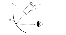
- the display device using the light guide 30 is used, a display device using the combiner 52 as shown in FIG. 3 can also be used.
- the display device 1a light constituting the image formed by the image forming unit 10 is reflected on the curved surface or flat surface of the combiner 52 through the virtual image display optical system 51, and enters the eye of the user. Thereby, the user can observe the virtual image displayed in front through the combiner 52.
- a head-up display can also be realized with the same configuration.
- the light source unit 11 including the LEDs emitting the three primary colors of red, green, and blue is used, a composite image or a monochrome image formed by combining one or two color images is displayed.
- the apparatus can be configured in the same manner as described above.
Landscapes
- Physics & Mathematics (AREA)
- General Physics & Mathematics (AREA)
- Optics & Photonics (AREA)
- Instrument Panels (AREA)
Abstract
所定の角度以上の入射角度で入射する光を全反射する壁面を内部に有する光学部材131と、前記壁面に対して前記所定の角度以上の入射角度で入射するように光を照射する光源部11と、それぞれが外部からの制御信号により第1方向と第2方向にその向きを変更可能な反射面を有する複数の反射部を二次元的に配列してなる反射型表示素子14であって、前記第1方向を向く反射面が前記内面で反射された光をその入射方向と異なる向きに反射するように配置された反射型表示素子14とを有する画像形成部10と、該画像形成部10から出射する光を平行光に変換するコリメート光学系20と、前記平行光を拡大するライトガイド30とを備える表示装置1。
Description
本発明は、光束(射出瞳)を拡大するライトガイドを備えたヘッドマウントディスプレイ(HMD: Head Mount Display)、ヘッドアップディスプレイ(HUD: Head-Up Display)等の虚像光学系を含む表示装置に関する。
自動車では、スクリーンに表示した文字や画像を投影し、コンバイナを含む虚像光学系を介して運転者の眼前に虚像を形成するヘッドアップディスプレイが使用されている。また、航空機ではヘッドアップディスプレイに加え、同様の仕組みにより、操縦者が頭部に着用するヘルメットに設けられたコンバイナを含む虚像光学系により、文字や画像を投影して操縦者の眼前に虚像を形成するヘッドマウントディスプレイが使用されている。こうした表示装置は、コンパクトに装置を構成するために、光源及び表示素子を有する画像形成部とコリメータ光学系で形成した小さな光束(射出瞳)の表示をライトガイドに導入して拡大表示する方式が用いられている(例えば特許文献1~4)。その表示素子としては、透過型液晶表示素子、反射型液晶表示素子、デジタルマイクロミラーデバイス(DMD)などが用いられる。
画像形成部、コリメータ光学系、及びライトガイドを組み合わせてなる表示装置について、従来用いられている構成の一例を図1に示す。この表示装置100は、光源部111、偏光板112、偏光ビームスプリッター113、デジタルマイクロミラーデバイス114、1/4λ波長板115、及び前記光源部111と前記デジタルマイクロミラーデバイス114の動作を制御する制御部116を有する画像形成部110と、コリメート光学系120と、ライトガイド130とを備えている。デジタルマイクロミラーデバイス114は、それぞれが1画素に対応する、格子状に配置された多数のミラーと、該多数のミラーの反射面の角度を個別に変更する駆動部を備えた表示素子であり、制御部116による制御の下で該駆動部に所定の電圧を印加することにより各画素のON状態とOFF状態を切り替えることができる。
着色画像を表示する表示装置では、光源部111は赤色、緑色、青色という3原色の光を発するLED光源を備えており、各LED光源から各色の無偏光のパルス光が順に繰り返し発せられる。光源部111から発せられた無偏光の光は偏光板112に導入され、所定の偏光の光(例えばS偏光の光)が取り出されて偏光ビームスプリッター113に入射する。偏光ビームスプリッター113は、その内部に前記所定の偏光の光(S偏光の光)を反射する反射面を有しており、該反射面によって前記所定の偏光の光(S偏光の光)が反射され、1/4λ波長板115を通ってデジタルマイクロミラーデバイス114に照射される。デジタルマイクロミラーデバイス114に照射された光のうち、ON状態のミラーの箇所の光のみが該ミラーで反射され、再び1/4λ波長板115を通って偏光ビームスプリッター113に入射する。偏光ビームスプリッター113とデジタルマイクロミラーデバイス114の間を往復した前記所定の偏光の光(S偏光の光)は、1/4λ波長板115を2度通過することで、偏光状態が(P偏光に)変換される。所定の画素のみで反射され(従って、画像が形成され)、偏光状態が(P偏光に)変換された光は再び偏光ビームスプリッター113に入射して前記反射面を通過し、コリメート光学系120で平行光に変換されてライトガイド130に導入される。ライトガイド130では、画像形成部110とコリメート光学系120で形成された画像の光束(射出瞳)が拡大される。
"SmartEyeglass Developer Edition",[online], ソニーモバイルコミュニケーションズ株式会社,[平成29年10月24日検索],インターネット<URL: https://developer.sonymobile.com/ja/smarteyeglass/>
ライトガイドを備えた虚像光学系を含む表示装置では、表示画像の視認性を高めるために高輝度化が求められる。特に、上述の表示装置では、画像形成部とコリメータ光学系で形成した画像の光束をライトガイドで拡大して表示するため、画像形成部において高輝度の画像を形成する必要がある。しかし、図1に示す従来の画像形成部では、各色のLED光源から発せられた無偏光の光のうち、S偏光(あるいはP偏光)の光しか使用されず、LED光源から発せられた光量の約半分が無駄になってしまうため、画像を高輝度化することが難しいという問題があった。
本発明が解決しようとする課題は、光源から発せられた光を有効に用いることができる、ライトガイドを備えた虚像光学系を含む表示装置を提供することである。
上記課題を解決するために成された本発明に係る表示装置は、
a) 所定の角度以上の入射角度で入射する光を全反射する壁面を内部に有する光学部材と、
b) 前記壁面に対して前記所定の角度以上の入射角度で入射するように光を照射する光源部と、
c) それぞれが外部からの制御信号により第1方向と第2方向にその向きを変更可能な反射面を有する複数の反射部を二次元的に配列してなる反射型表示素子であって、前記第1方向を向く反射面が前記壁面で反射された光をその入射方向と異なる向きに反射するように配置された反射型表示素子と
を有する画像形成部と、
d) 前記画像形成部から出射する光を平行光に変換するコリメート光学系と、
e) 前記平行光を拡大するライトガイドと
を備えることを特徴とする。
a) 所定の角度以上の入射角度で入射する光を全反射する壁面を内部に有する光学部材と、
b) 前記壁面に対して前記所定の角度以上の入射角度で入射するように光を照射する光源部と、
c) それぞれが外部からの制御信号により第1方向と第2方向にその向きを変更可能な反射面を有する複数の反射部を二次元的に配列してなる反射型表示素子であって、前記第1方向を向く反射面が前記壁面で反射された光をその入射方向と異なる向きに反射するように配置された反射型表示素子と
を有する画像形成部と、
d) 前記画像形成部から出射する光を平行光に変換するコリメート光学系と、
e) 前記平行光を拡大するライトガイドと
を備えることを特徴とする。
前記光学部材には、例えばプリズムを用いることができ、その場合、前記壁面は該プリズムの内壁面とすることができる。
前記反射型表示素子は、例えばデジタルマイクロミラーデバイスである。前記二次元的な配列は、典型的には格子状の配列であるが、ハニカム状等の配列であってもよい。前記第1方向は、外部からの制御信号によって反射部がON状態とされたときの反射面の向きに相当し、前記第2方向は、反射部がOFF状態とされたときの反射面の向きに相当する。そして、第1方向を向く反射面により反射された光により画像が形成される。
前記反射型表示素子は、例えばデジタルマイクロミラーデバイスである。前記二次元的な配列は、典型的には格子状の配列であるが、ハニカム状等の配列であってもよい。前記第1方向は、外部からの制御信号によって反射部がON状態とされたときの反射面の向きに相当し、前記第2方向は、反射部がOFF状態とされたときの反射面の向きに相当する。そして、第1方向を向く反射面により反射された光により画像が形成される。
本発明に係る表示装置では、光源部から、光学部材内部の壁面に対して臨界角(前記所定の角度)以上の入射角度で入射するように光を照射する。該壁面で全反射した光は反射型表示素子に入射する。反射型表示素子を構成する複数の反射部がそれぞれ備える反射面のうち、第1方向を向く(ON状態に制御された)反射面は、該反射面への光の入射方向と異なる向きに(即ち、光源部に反射光が戻らないように)光を反射する。この反射光により画像が形成される。本発明に係る表示装置では、光源部からの光を光学部材内部の壁面で全反射させて反射型表示素子に入射させるため、光源から発せられた光を有効に用いて効率よく表示画像を高輝度化することができる。
本発明に係る表示装置では、前記光源部が、互いに波長が異なる複数の光を順に繰り返し発するものとすることができる。該繰り返しの周波数を、人が識別可能な周波数よりも十分に大きくすることにより、形成した画像を複数の色の画像を合成してなる合成画像として視認させることができる。
本発明に係る表示装置は、
前記光学部材が三角柱状の第1プリズムであり、さらに、
f) 前記第1の方向を向く複数の反射面により反射され前記第1プリズムを通過した光が入射する位置に設けられ、前記第1プリズムの内部での光路長差を補償するように配置された第2プリズム
を備えることが好ましい。
前記光学部材が三角柱状の第1プリズムであり、さらに、
f) 前記第1の方向を向く複数の反射面により反射され前記第1プリズムを通過した光が入射する位置に設けられ、前記第1プリズムの内部での光路長差を補償するように配置された第2プリズム
を備えることが好ましい。
上記の要件を満たす限りにおいて、前記第2プリズムは、前記第1プリズムと同一形状のものであってもよく、異なる形状のものであってもよい。また、第1プリズムと第2プリズムは、両者の一面が平行に配置されていてもよく、非平行に配置されていてもよい。
この態様の表示装置は、例えば2個の同一形状の三角柱状のプリズム(三角プリズム)を、平面視して平行四辺形(直角プリズムの場合には長方形)となるように配置することにより構成することができる。これにより、第1の方向を向く反射面で反射され画像を形成する光が第1プリズム及び第2プリズムの内部を通過する距離(光路長)が均一になり、光学系の設計が容易になる。
2個の三角柱状のプリズムを備えた上記態様の表示装置では、
前記第1プリズム及び前記第2プリズムが直角プリズムであり、互いの斜面が平行に対向配置されている
ことが好ましい。これにより、2個のプリズムを組み合わせた外形を直方体状にして表示装置を小型化することができる。
前記第1プリズム及び前記第2プリズムが直角プリズムであり、互いの斜面が平行に対向配置されている
ことが好ましい。これにより、2個のプリズムを組み合わせた外形を直方体状にして表示装置を小型化することができる。
さらに、本発明に係る表示装置では、
前記光源部が、前記光学部材に対して垂直に光を入射する
ことが好ましい。これにより、光源部と光学部材の間の距離を短くして表示装置を小型化することができる。
前記光源部が、前記光学部材に対して垂直に光を入射する
ことが好ましい。これにより、光源部と光学部材の間の距離を短くして表示装置を小型化することができる。
さらに、本発明に係る表示装置では、
前記反射型表示素子が有する複数の反射面のうちの所定の反射面が前記第1方向を向いたときの反射光の主光線が前記光学部材に対して垂直に入射する
ことが好ましい。これにより、反射型表示素子と光学部材の間の距離を短くして表示装置を小型化することができる。
前記反射型表示素子が有する複数の反射面のうちの所定の反射面が前記第1方向を向いたときの反射光の主光線が前記光学部材に対して垂直に入射する
ことが好ましい。これにより、反射型表示素子と光学部材の間の距離を短くして表示装置を小型化することができる。
前記所定の反射面とは、画像の形成に用いられる反射面のうち中心に位置する反射面(中心画素)である。例えば、反射型表示素子が有する複数の反射面の全てに光を照射して画像を形成する構成では、該所定の反射面は二次元的に配列された(反射部の)反射面のうち、その中心に位置する反射面となる。また、反射型表示素子が有する複数の反射面のうちの一部の反射面に光を照射して画像を形成する構成では、該一部の反射面の中心に位置する反射面となる。
本発明に係る表示装置を用いることにより、光源から発せられた光を有効に用いることができる。
本発明に係る本発明に係る表示装置の一実施例について、以下、図面を参照して説明する。
図2は、本実施例の表示装置の概略構成図である。この表示装置は、画像形成部10、コリメート光学系20、及びライトガイド30を備えている。画像形成部10は、光源部11、同一形状の直角プリズムである第1プリズム131と第2プリズム132からなる光学部材13、及びデジタルマイクロミラーデバイス14を備えている。第1プリズム131と第2プリズム132は、互いの斜面がわずかに離間した状態に対向配置されており、それらを組み合わせた外形は直方体状に(従って、同一形状の面が全て互いに平行に位置した状態に)なっている。なお、本実施例では2個の直角プリズムを用いているが、同一形状または異形状の2個の三角プリズムを、上面視して四角形となるように組み合わせた光学部材を用いることもできる。
光源部11は、赤色LED、緑色LED、及び青色LEDと拡散板を有している。制御部16からの制御信号に従って、赤色LED、緑色LED、及び青色LEDから順に繰り返し発せられた光は拡散板で面状の光に広げられる。赤色LED、緑色LED、及び青色LEDはそれぞれ出射光の光量を調整可能であり、各色の光の光量を適宜に変更することにより形成する画像の配色を調整することができる。なお、本実施例では、LEDから発せられた各色の光を面状に拡げる構成を採っているが、LEDから発せられる各色の光を高速で二次元走査する光源部を用いることもできる。
デジタルマイクロミラーデバイス14は、それぞれが1画素に対応する、格子状に配置された多数のミラーと、該多数のミラーの反射面の角度を個別に変更する駆動部を備えた表示素子である。制御部16による制御の下で該駆動部に所定の電圧を印加することにより各画素のON状態とOFF状態を切り替えることができる。各ミラーはON状態においてその反射面が第1方向を、OFF状態において第2方向を向くように制御される。
本実施例の画像形成部10では、3個のLEDから発せられる光が、人が発光の切り替わりを識別可能な周波数よりも十分に高い周波数で切り替えられ、デジタルマイクロミラーデバイス14が有する各ミラーの反射面の角度もこれに追従して制御されるため、ライトガイド30に表示する画像をこれら各色の画像を合成した合成画像として視認させることができる。
光源部11から発せられた面状の光は、第1プリズム131に対して垂直に入射する。そして、第1プリズム131の内部から斜面に所定の角度で入射する。この所定の角度とは、第1プリズム131の媒質を通り斜面に到達した光が大気中に出射せず全反射される角度(臨界角)よりも大きい角度であることを意味し、その角度は第1プリズム131の媒質によって異なる。本実施例では、第1プリズム131の媒質がN-BK-7(屈折率1.52)であることから、その臨界角は41度であり、これよりも大きな入射角度となるように、光を斜面に対して照射する。第1プリズム131には、N-BK-7以外の材料(例えばガラス、樹脂等)からなるものを用いることもでき、第1プリズム131の内部において斜面に入射する角度は、使用する材料の屈折率に応じた角度に(即ち該斜面で全反射されるように)調整される。
第1プリズム131の内部で全反射された光は、第1プリズム131を出射しデジタルマイクロミラーデバイス14に入射する。上述のとおり、デジタルマイクロミラーデバイス14の各ミラーは反射面が第1方向を向くON状態、あるいは第2方向を向くOFF状態に制御されている。第1方向を向くON状態に制御されたミラーからの反射光(即ち画像を構成する光)は、第1プリズム131に入射する。一方、OFF状態に制御されたミラーからの反射光は、第1プリズム131に入射しない方向に向かう。
本実施例の画像形成部10では、デジタルマイクロミラーデバイス14は第1プリズム131の一側面に平行に配置されており、このように配置したときにデジタルマイクロミラーデバイス14(内のON状態に制御されたミラー)の中心画素からの反射光の主光線が第1プリズム131に対して垂直に入射するような角度の斜面を持つ第1プリズム131が用いられる。なお、デジタルマイクロミラーデバイス14(内のON状態に制御されたミラー)の中心画素からの反射光の主光線とは、画像の形成に使用するミラーのうち中心に位置するミラー(中心画素)からの反射光(光束)の中心を通る光線をいう。
本実施例の表示装置1では、このように、画像形成部10において光源部11から発せられる面状の光を第1プリズム131に対して垂直に入射させる構成を採っているため、光源部11と第1プリズム131の間の距離を短くすることができる。また、デジタルマイクロミラーデバイス14(内のON状態に制御されたミラー)の中心画素からの反射光の主光線を第1プリズム131に垂直に入射する構成を採っているため、デジタルマイクロミラーデバイス14と第1プリズム131の間の距離を短くすることができる。このような構成を採ることにより画像形成部10が小型化され、これにより表示装置1も小型化することができる。
デジタルマイクロミラーデバイス14から第1プリズム131に入射した光は、そのまま第1プリズム131を通過し、続いて第2プリズム132に入射しこれも通過する。本実施例の画像形成部10では、同一形状である第1プリズム131と第2プリズム132を、それらを組み合わせた外形が直方体状になるように配置しているため、デジタルマイクロミラーデバイス14(内のON状態に制御されたミラー)からの反射光の光路長がミラーの位置に関わらず均一になり、光学系の設計が容易になる。
画像形成部10で形成された画像(を形成する光)は、続いてコリメートレンズ等からなるコリメート光学系20において平行光に変換され、ライトガイド30に導入される。ライトガイド30は光学ガラス(BK7等)からなる板状の光学部材であり、その内部の一方の側に反射面301が形成され、他方の側には複数の半透過面302が形成されている。ライトガイド30の前記一方の側に導入された光は反射面301で反射され、ライトガイド30の内部で全反射を繰り返しながら他方の側に向かい、複数の半透過面302で反射されてライトガイド30の外部に出射する。これにより、画像形成部10で形成された画像の光束(射出瞳)が拡大される。なお、本実施例では、反射面301及び複数の半透過面302を有するライトガイド30を用いているが、他の構成を有するライトガイドを使用することもできる。例えば、反射面301に代えて透過及び/又は屈折によって画像の光束を入射させるものや、半透過面302に代えてホログラム面(例えば非特許文献1)を有するものを用いることができる。
本実施例の表示装置1では、光源部11から発せられた面状の光を、臨界角以上の入射角度で第1プリズム131の内部の壁面に照射して全反射させ、デジタルマイクロミラーデバイス14に入射する構成を採っている。そのため、偏光ビームスプリッターを用いる従来の表示装置のように光源部で発せられた光量が失われることがなくその光量を有効に用いて高輝度の画像を形成することができる。特に、本実施例の表示装置1のように、画像形成部10で形成した画像の光束をライトガイド30で拡大する場合には、光束(射出瞳)の拡大に伴って輝度が低下するため、光源部11から発せられた光量を有効に利用できる本実施例の構成を好適に用いることができる。
上記実施例は本発明に係る表示装置に関する好ましい一例であって、本発明の趣旨に沿って適宜に変更することができる。
上記実施例では、第1プリズム131及び第2プリズム132を組み合わせて光学部材13を構成したが、第1プリズム131のみを用いても、上記実施例と同様に光源部11から発せられた光量を有効に用いることができる。また、この場合は、デジタルマイクロミラーデバイス14で反射した光を第1プリズム131に入射させず、直接コリメート光学系20に入射するようにしても良い。あるいは、第1プリズムに代えて、その内部で光を全反射することが可能な適宜の形状のガラス板等を用いて構成することもできる。
上記実施例では、第1プリズム131及び第2プリズム132を組み合わせて光学部材13を構成したが、第1プリズム131のみを用いても、上記実施例と同様に光源部11から発せられた光量を有効に用いることができる。また、この場合は、デジタルマイクロミラーデバイス14で反射した光を第1プリズム131に入射させず、直接コリメート光学系20に入射するようにしても良い。あるいは、第1プリズムに代えて、その内部で光を全反射することが可能な適宜の形状のガラス板等を用いて構成することもできる。
さらに、上記実施例では、ライトガイド30を用いた表示装置としたが、図3に示すような、コンバイナ52を用いた表示装置にすることもできる。この表示装置1aでは、画像形成部10で形成した画像を構成する光は、虚像表示光学系51を通して曲面状または平面状であるコンバイナ52上で反射され、使用者の眼に入射する。これにより、使用者は前方に表示された虚像を、コンバイナ52を通して観測することができる。同様の構成で、ヘッドアップディスプレイを実現することもできる。
上記実施例では、赤色、緑色、青色の3原色をそれぞれ発するLEDを備えた光源部11を用いる構成としたが、1色あるいは2色の画像を合成してなる合成画像やモノクロ画像を表示する装置についても上記同様に構成することができる。
1、1a…表示装置
10…画像形成部
11…光源
13…光学部材
131…第1プリズム
132…第2プリズム
14…デジタルマイクロミラーデバイス
16…制御部
20…コリメート光学系
30…ライトガイド
301…全反射面
302…半透過面
51…虚像表示光学系
52…コンバイナ
10…画像形成部
11…光源
13…光学部材
131…第1プリズム
132…第2プリズム
14…デジタルマイクロミラーデバイス
16…制御部
20…コリメート光学系
30…ライトガイド
301…全反射面
302…半透過面
51…虚像表示光学系
52…コンバイナ
Claims (7)
- a) 所定の角度以上の入射角度で入射する光を全反射する壁面を内部に有する光学部材と、
b) 前記壁面に対して前記所定の角度以上の入射角度で入射するように光を照射する光源部と、
c) それぞれが外部からの制御信号により第1方向と第2方向にその向きを変更可能な反射面を有する複数の反射部を二次元的に配列してなる反射型表示素子であって、前記第1方向を向く反射面が前記内面で反射された光をその入射方向と異なる向きに反射するように配置された反射型表示素子と
を有する画像形成部と、
d) 前記画像形成部から出射する光を平行光に変換するコリメート光学系と、
e) 前記平行光を拡大するライトガイドと
を備えることを特徴とする表示装置。 - 前記光源部が、互いに波長が異なる複数の光を順に繰り返し発するものである
ことを特徴とする請求項1に記載の表示装置。 - 前記光学部材が三角柱状の第1プリズムであり、さらに、
f) 前記第1の方向を向く複数の反射面により反射され前記第1プリズムを通過した光が入射する位置に設けられ、前記第1プリズムの内部での光路長差を補償するように配置された第2プリズム
を備えることを特徴とする請求項1に記載の表示装置。 - 前記第1プリズム及び前記第2プリズムが直角プリズムであり、互いの斜面が平行に対向配置されている
ことを特徴とする請求項3に記載の表示装置。 - 前記光源部が、前記光学部材に対して垂直に光を入射する
ことを特徴とする請求項1に記載の表示装置。 - 前記反射型表示素子が有する複数の反射面のうちの所定の反射面が前記第1方向を向いたときの反射光の主光線が前記光学部材に対して垂直に入射する
ことを特徴とする請求項1に記載の表示装置 - a) 所定の角度以上の入射角度で入射する光を全反射する壁面を内部に有する光学部材と、
b) 前記壁面に対して前記所定の角度以上の入射角度で入射するように光を照射する光源部と、
c) それぞれが外部からの制御信号により第1方向と第2方向にその向きを変更可能な反射面を有する複数の反射部を二次元的に配列してなる反射型表示素子であって、前記第1方向を向く反射面が前記内面で反射された光をその入射方向と異なる向きに反射するように配置された反射型表示素子と
を有する画像形成部と
d) 眼前に配置した平面又は曲面形状の半透過面を含む虚像表示光学系と
を備えることを特徴とする表示装置。
Priority Applications (4)
| Application Number | Priority Date | Filing Date | Title |
|---|---|---|---|
| EP17932069.2A EP3712681A4 (en) | 2017-11-17 | 2017-11-17 | DISPLAY DEVICE |
| PCT/JP2017/041552 WO2019097695A1 (ja) | 2017-11-17 | 2017-11-17 | 表示装置 |
| US16/756,984 US20210373321A1 (en) | 2017-11-17 | 2017-11-17 | Display device |
| JP2019553645A JPWO2019097695A1 (ja) | 2017-11-17 | 2017-11-17 | 表示装置 |
Applications Claiming Priority (1)
| Application Number | Priority Date | Filing Date | Title |
|---|---|---|---|
| PCT/JP2017/041552 WO2019097695A1 (ja) | 2017-11-17 | 2017-11-17 | 表示装置 |
Publications (1)
| Publication Number | Publication Date |
|---|---|
| WO2019097695A1 true WO2019097695A1 (ja) | 2019-05-23 |
Family
ID=66539425
Family Applications (1)
| Application Number | Title | Priority Date | Filing Date |
|---|---|---|---|
| PCT/JP2017/041552 Ceased WO2019097695A1 (ja) | 2017-11-17 | 2017-11-17 | 表示装置 |
Country Status (4)
| Country | Link |
|---|---|
| US (1) | US20210373321A1 (ja) |
| EP (1) | EP3712681A4 (ja) |
| JP (1) | JPWO2019097695A1 (ja) |
| WO (1) | WO2019097695A1 (ja) |
Cited By (4)
| Publication number | Priority date | Publication date | Assignee | Title |
|---|---|---|---|---|
| KR102156417B1 (ko) * | 2019-05-28 | 2020-09-15 | (주)엘비전테크 | 스위칭 미러 렌즈를 이용한 See-through 광학 시스템 |
| CN112285930A (zh) * | 2019-07-22 | 2021-01-29 | 苹果公司 | 用于头戴式设备的光学对准 |
| CN113109945A (zh) * | 2021-04-14 | 2021-07-13 | 安徽中科光栅科技有限公司 | 波导显示装置 |
| JP2022553689A (ja) * | 2019-10-23 | 2022-12-26 | ルムス エルティーディー. | 均一性および/または目の安全性が強化されたレーザ照明ディスプレイ |
Families Citing this family (1)
| Publication number | Priority date | Publication date | Assignee | Title |
|---|---|---|---|---|
| TW202346937A (zh) * | 2022-04-03 | 2023-12-01 | 以色列商魯姆斯有限公司 | 採用與光導集成的二向色組合器的顯示器 |
Citations (7)
| Publication number | Priority date | Publication date | Assignee | Title |
|---|---|---|---|---|
| JP2013117668A (ja) * | 2011-12-05 | 2013-06-13 | Nikon Corp | スペックル低減装置、プロジェクタ、およびスペックル低減装置の製造方法 |
| JP5299391B2 (ja) | 2004-03-29 | 2013-09-25 | ソニー株式会社 | 画像表示装置 |
| JP5698297B2 (ja) | 2000-06-05 | 2015-04-08 | ラマス リミテッド | 基板によって誘導される光学ビーム拡大器 |
| JP2015184561A (ja) | 2014-03-25 | 2015-10-22 | ソニー株式会社 | 導光装置、画像表示装置及び表示装置 |
| JP2015184560A (ja) * | 2014-03-25 | 2015-10-22 | ソニー株式会社 | 導光装置、画像表示装置及び表示装置 |
| JP2016031401A (ja) * | 2014-07-28 | 2016-03-07 | パナソニックIpマネジメント株式会社 | 表示装置 |
| JP2018004817A (ja) * | 2016-06-29 | 2018-01-11 | 株式会社リコー | 画像表示装置およびヘッドアップディスプレイシステム |
Family Cites Families (5)
| Publication number | Priority date | Publication date | Assignee | Title |
|---|---|---|---|---|
| US6560018B1 (en) * | 1994-10-27 | 2003-05-06 | Massachusetts Institute Of Technology | Illumination system for transmissive light valve displays |
| JP2007288169A (ja) * | 2006-03-24 | 2007-11-01 | Ricoh Co Ltd | 光学素子、照明装置および画像表示装置 |
| US7483200B1 (en) * | 2008-01-14 | 2009-01-27 | Spatial Photonics, Inc. | Multiple stop micro-mirror array display |
| US9076368B2 (en) * | 2012-02-06 | 2015-07-07 | Battelle Memorial Institute | Image generation systems and image generation methods |
| US9494800B2 (en) * | 2014-01-21 | 2016-11-15 | Osterhout Group, Inc. | See-through computer display systems |
-
2017
- 2017-11-17 US US16/756,984 patent/US20210373321A1/en not_active Abandoned
- 2017-11-17 EP EP17932069.2A patent/EP3712681A4/en not_active Withdrawn
- 2017-11-17 JP JP2019553645A patent/JPWO2019097695A1/ja active Pending
- 2017-11-17 WO PCT/JP2017/041552 patent/WO2019097695A1/ja not_active Ceased
Patent Citations (8)
| Publication number | Priority date | Publication date | Assignee | Title |
|---|---|---|---|---|
| JP5698297B2 (ja) | 2000-06-05 | 2015-04-08 | ラマス リミテッド | 基板によって誘導される光学ビーム拡大器 |
| JP5299391B2 (ja) | 2004-03-29 | 2013-09-25 | ソニー株式会社 | 画像表示装置 |
| JP5447714B2 (ja) | 2004-03-29 | 2014-03-19 | ソニー株式会社 | 画像表示装置 |
| JP2013117668A (ja) * | 2011-12-05 | 2013-06-13 | Nikon Corp | スペックル低減装置、プロジェクタ、およびスペックル低減装置の製造方法 |
| JP2015184561A (ja) | 2014-03-25 | 2015-10-22 | ソニー株式会社 | 導光装置、画像表示装置及び表示装置 |
| JP2015184560A (ja) * | 2014-03-25 | 2015-10-22 | ソニー株式会社 | 導光装置、画像表示装置及び表示装置 |
| JP2016031401A (ja) * | 2014-07-28 | 2016-03-07 | パナソニックIpマネジメント株式会社 | 表示装置 |
| JP2018004817A (ja) * | 2016-06-29 | 2018-01-11 | 株式会社リコー | 画像表示装置およびヘッドアップディスプレイシステム |
Non-Patent Citations (2)
| Title |
|---|
| "SmartEyeglass Developer Edition", 24 October 2017, SONY MOBILE COMMUNICATIONS JAPAN, INC. |
| See also references of EP3712681A4 * |
Cited By (4)
| Publication number | Priority date | Publication date | Assignee | Title |
|---|---|---|---|---|
| KR102156417B1 (ko) * | 2019-05-28 | 2020-09-15 | (주)엘비전테크 | 스위칭 미러 렌즈를 이용한 See-through 광학 시스템 |
| CN112285930A (zh) * | 2019-07-22 | 2021-01-29 | 苹果公司 | 用于头戴式设备的光学对准 |
| JP2022553689A (ja) * | 2019-10-23 | 2022-12-26 | ルムス エルティーディー. | 均一性および/または目の安全性が強化されたレーザ照明ディスプレイ |
| CN113109945A (zh) * | 2021-04-14 | 2021-07-13 | 安徽中科光栅科技有限公司 | 波导显示装置 |
Also Published As
| Publication number | Publication date |
|---|---|
| EP3712681A4 (en) | 2020-11-11 |
| JPWO2019097695A1 (ja) | 2020-04-02 |
| EP3712681A1 (en) | 2020-09-23 |
| US20210373321A1 (en) | 2021-12-02 |
Similar Documents
| Publication | Publication Date | Title |
|---|---|---|
| JP7402543B2 (ja) | ダイクロイックビームスプリッタカラーコンバイナを有する光学デバイスおよび光学システム | |
| US7710655B2 (en) | Display with image-guiding substrate | |
| JP2022160457A (ja) | ウェアラブルディスプレイのための照明装置 | |
| JP4395802B2 (ja) | 画像表示装置 | |
| US20220317467A1 (en) | Optical Devices Having Dichroic Beam Combiners, Optical Devices for Use with Dichroic Beam Combiners, and Methods of Manufacture Therefor | |
| EP1626585B1 (en) | Illumination unit for an image projecting apparatus | |
| US11598971B2 (en) | Image device with a compact homogenizer | |
| JP2003329978A (ja) | 照明装置および投射型表示装置 | |
| KR101976991B1 (ko) | 웨어러블 디스플레이 장치 | |
| US12613426B2 (en) | Method and system for projection display with polarization selective reflectors | |
| JPWO2019097695A1 (ja) | 表示装置 | |
| CN109239835A (zh) | 波导、成像扩展模组、光源模组、近眼显示系统及设备 | |
| EP3843866A1 (en) | Dynamic incoupling gratings in imaging systems | |
| JP5239237B2 (ja) | 画像投影装置 | |
| CN112513718A (zh) | 用于rgb照明器的方法和系统 | |
| JP2010072012A (ja) | 画像投射装置 | |
| JP2008107521A (ja) | 光源装置、照明装置及び画像表示装置 | |
| KR20220086456A (ko) | 3차원 증강 현실을 제공하는 증강 현실 장치 및 그 동작 방법 | |
| KR100767671B1 (ko) | 휴대가능한 프로젝터용 광학시스템 | |
| JP2001194723A (ja) | 映像表示装置 | |
| CN117826427A (zh) | 一种光机及ar设备 | |
| JP2007279436A (ja) | 投射型画像表示装置 | |
| CN121069693A (zh) | 一种照明系统及偏振成像设备 | |
| JP2009047881A (ja) | プロジェクタ | |
| JP2006145720A (ja) | 偏光変換素子、照明装置、及びプロジェクタ |
Legal Events
| Date | Code | Title | Description |
|---|---|---|---|
| 121 | Ep: the epo has been informed by wipo that ep was designated in this application |
Ref document number: 17932069 Country of ref document: EP Kind code of ref document: A1 |
|
| ENP | Entry into the national phase |
Ref document number: 2019553645 Country of ref document: JP Kind code of ref document: A |
|
| NENP | Non-entry into the national phase |
Ref country code: DE |
|
| ENP | Entry into the national phase |
Ref document number: 2017932069 Country of ref document: EP Effective date: 20200617 |