WO2019097741A1 - 表示装置及び表示方法 - Google Patents
表示装置及び表示方法 Download PDFInfo
- Publication number
- WO2019097741A1 WO2019097741A1 PCT/JP2018/014489 JP2018014489W WO2019097741A1 WO 2019097741 A1 WO2019097741 A1 WO 2019097741A1 JP 2018014489 W JP2018014489 W JP 2018014489W WO 2019097741 A1 WO2019097741 A1 WO 2019097741A1
- Authority
- WO
- WIPO (PCT)
- Prior art keywords
- unit
- image
- power
- mode
- power supply
- Prior art date
- Legal status (The legal status is an assumption and is not a legal conclusion. Google has not performed a legal analysis and makes no representation as to the accuracy of the status listed.)
- Ceased
Links
Images





Classifications
-
- G—PHYSICS
- G06—COMPUTING OR CALCULATING; COUNTING
- G06F—ELECTRIC DIGITAL DATA PROCESSING
- G06F1/00—Details not covered by groups G06F3/00 - G06F13/00 and G06F21/00
- G06F1/26—Power supply means, e.g. regulation thereof
- G06F1/32—Means for saving power
- G06F1/3203—Power management, i.e. event-based initiation of a power-saving mode
- G06F1/3206—Monitoring of events, devices or parameters that trigger a change in power modality
- G06F1/3212—Monitoring battery levels, e.g. power saving mode being initiated when battery voltage goes below a certain level
-
- G—PHYSICS
- G06—COMPUTING OR CALCULATING; COUNTING
- G06F—ELECTRIC DIGITAL DATA PROCESSING
- G06F1/00—Details not covered by groups G06F3/00 - G06F13/00 and G06F21/00
- G06F1/26—Power supply means, e.g. regulation thereof
- G06F1/32—Means for saving power
- G06F1/3203—Power management, i.e. event-based initiation of a power-saving mode
- G06F1/3206—Monitoring of events, devices or parameters that trigger a change in power modality
- G06F1/3228—Monitoring task completion, e.g. by use of idle timers, stop commands or wait commands
-
- G—PHYSICS
- G06—COMPUTING OR CALCULATING; COUNTING
- G06F—ELECTRIC DIGITAL DATA PROCESSING
- G06F1/00—Details not covered by groups G06F3/00 - G06F13/00 and G06F21/00
- G06F1/26—Power supply means, e.g. regulation thereof
- G06F1/32—Means for saving power
- G06F1/3203—Power management, i.e. event-based initiation of a power-saving mode
- G06F1/3206—Monitoring of events, devices or parameters that trigger a change in power modality
- G06F1/3231—Monitoring the presence, absence or movement of users
-
- G—PHYSICS
- G06—COMPUTING OR CALCULATING; COUNTING
- G06F—ELECTRIC DIGITAL DATA PROCESSING
- G06F1/00—Details not covered by groups G06F3/00 - G06F13/00 and G06F21/00
- G06F1/26—Power supply means, e.g. regulation thereof
- G06F1/32—Means for saving power
- G06F1/3203—Power management, i.e. event-based initiation of a power-saving mode
- G06F1/3234—Power saving characterised by the action undertaken
- G06F1/325—Power saving in peripheral device
- G06F1/3262—Power saving in digitizer or tablet
-
- G—PHYSICS
- G06—COMPUTING OR CALCULATING; COUNTING
- G06F—ELECTRIC DIGITAL DATA PROCESSING
- G06F1/00—Details not covered by groups G06F3/00 - G06F13/00 and G06F21/00
- G06F1/26—Power supply means, e.g. regulation thereof
- G06F1/32—Means for saving power
- G06F1/3203—Power management, i.e. event-based initiation of a power-saving mode
- G06F1/3234—Power saving characterised by the action undertaken
- G06F1/325—Power saving in peripheral device
- G06F1/3265—Power saving in display device
-
- G—PHYSICS
- G06—COMPUTING OR CALCULATING; COUNTING
- G06F—ELECTRIC DIGITAL DATA PROCESSING
- G06F3/00—Input arrangements for transferring data to be processed into a form capable of being handled by the computer; Output arrangements for transferring data from processing unit to output unit, e.g. interface arrangements
- G06F3/01—Input arrangements or combined input and output arrangements for interaction between user and computer
- G06F3/03—Arrangements for converting the position or the displacement of a member into a coded form
- G06F3/041—Digitisers, e.g. for touch screens or touch pads, characterised by the transducing means
- G06F3/0412—Digitisers structurally integrated in a display
-
- H—ELECTRICITY
- H04—ELECTRIC COMMUNICATION TECHNIQUE
- H04M—TELEPHONIC COMMUNICATION
- H04M1/00—Substation equipment, e.g. for use by subscribers
- H04M1/72—Mobile telephones; Cordless telephones, i.e. devices for establishing wireless links to base stations without route selection
- H04M1/725—Cordless telephones
- H04M1/73—Battery saving arrangements
-
- H—ELECTRICITY
- H04—ELECTRIC COMMUNICATION TECHNIQUE
- H04W—WIRELESS COMMUNICATION NETWORKS
- H04W4/00—Services specially adapted for wireless communication networks; Facilities therefor
- H04W4/02—Services making use of location information
- H04W4/021—Services related to particular areas, e.g. point of interest [POI] services, venue services or geofences
-
- G—PHYSICS
- G06—COMPUTING OR CALCULATING; COUNTING
- G06F—ELECTRIC DIGITAL DATA PROCESSING
- G06F3/00—Input arrangements for transferring data to be processed into a form capable of being handled by the computer; Output arrangements for transferring data from processing unit to output unit, e.g. interface arrangements
- G06F3/01—Input arrangements or combined input and output arrangements for interaction between user and computer
- G06F3/048—Interaction techniques based on graphical user interfaces [GUI]
- G06F3/0487—Interaction techniques based on graphical user interfaces [GUI] using specific features provided by the input device, e.g. functions controlled by the rotation of a mouse with dual sensing arrangements, or of the nature of the input device, e.g. tap gestures based on pressure sensed by a digitiser
- G06F3/0488—Interaction techniques based on graphical user interfaces [GUI] using specific features provided by the input device, e.g. functions controlled by the rotation of a mouse with dual sensing arrangements, or of the nature of the input device, e.g. tap gestures based on pressure sensed by a digitiser using a touch-screen or digitiser, e.g. input of commands through traced gestures
-
- Y—GENERAL TAGGING OF NEW TECHNOLOGICAL DEVELOPMENTS; GENERAL TAGGING OF CROSS-SECTIONAL TECHNOLOGIES SPANNING OVER SEVERAL SECTIONS OF THE IPC; TECHNICAL SUBJECTS COVERED BY FORMER USPC CROSS-REFERENCE ART COLLECTIONS [XRACs] AND DIGESTS
- Y02—TECHNOLOGIES OR APPLICATIONS FOR MITIGATION OR ADAPTATION AGAINST CLIMATE CHANGE
- Y02D—CLIMATE CHANGE MITIGATION TECHNOLOGIES IN INFORMATION AND COMMUNICATION TECHNOLOGIES [ICT], I.E. INFORMATION AND COMMUNICATION TECHNOLOGIES AIMING AT THE REDUCTION OF THEIR OWN ENERGY USE
- Y02D10/00—Energy efficient computing, e.g. low power processors, power management or thermal management
Definitions
- the present invention relates to user interface technology.
- Patent Document 1 a liquid crystal panel and electronic paper (a display medium having a feature that an image does not disappear even after the power is turned off) are stacked on the same electrode substrate, and transition to a sleep mode is made.
- a technology is disclosed that causes the electronic paper to display a default display screen during the sleep function operation when the power of the is turned off.
- an object of this invention is to suppress the power consumption of a touch-screen part, maintaining the convenience of communication.
- a power supply unit for supplying power to each unit of the apparatus, a communication unit for performing communication, a touch screen unit for receiving display and touch operations, and a first condition When satisfied, the power supply unit does not supply power for the touch operation from the power supply unit while the image displayed by the touch screen unit is maintained, and power from the power supply unit to the communication unit
- a display device includes: a control unit that switches the device to a first operation mode that is an operation mode in which supply is performed.
- the touch screen unit consumes power for rewriting an image to be displayed and does not consume power for maintaining the rewritten image
- the control unit is configured to maintain the image by the touch screen unit.
- An operation mode in which power supply from the power supply unit to the touch screen unit is not performed may be switched as the first operation mode.
- the control unit may further include a detection unit that detects an event occurring in the own device, and the control unit may temporarily switch the power supply unit to the touch screen unit when the detection unit detects an event in the first operation mode. Power may be supplied to rewrite the image displayed on the touch screen unit with an image corresponding to the event.
- the measurement unit includes a measurement unit that measures the position of the own device, the detection unit detects measurement of a predetermined position by the measurement unit as the event, and the control unit is configured to use the detection unit in the first operation mode.
- the power supply unit temporarily supplies power to the touch screen unit, and an image displayed on the touch screen unit is an image according to the position May be rewritten.
- the control unit may further include an operation reception unit configured to receive an operation of the user, the detection unit detecting reception of an operation by the operation reception unit, and the control unit may perform the operation reception unit by the operation reception unit in the first operation mode.
- an operation reception unit configured to receive an operation of the user
- the detection unit detecting reception of an operation by the operation reception unit
- the control unit may perform the operation reception unit by the operation reception unit in the first operation mode.
- power may be temporarily supplied from the power supply unit to the touch screen unit, and an image displayed on the touch screen unit may be rewritten with an image corresponding to the operation.
- the control unit when the data is received by the communication unit in the first operation mode, the control unit temporarily supplies power from the power supply unit to the touch screen unit, and the power is displayed on the touch screen unit. The image may be rewritten to an image according to the data received by the communication unit. Further, the control unit sets the device in a second operation mode, which is an operation mode in which power supply from the power supply unit to the touch screen unit and the communication unit is performed, when the second condition is satisfied. You may switch.
- a second operation mode which is an operation mode in which power supply from the power supply unit to the touch screen unit and the communication unit is performed, when the second condition is satisfied. You may switch.
- control unit when the third condition is satisfied, the control unit rewrites the image displayed on the touch screen unit to a predetermined image, and then the control unit causes any one of the units of the own device to read from the power supply unit.
- the device may be switched to the third operation mode, which is an operation mode in which power is not supplied.
- the power supply unit has a battery
- the third condition includes a plurality of conditions including a fourth condition to be satisfied when the battery is exhausted
- the control unit is configured to When one of the conditions is satisfied, the image displayed on the touch screen unit is rewritten to an image according to whether the satisfied condition is the fourth condition, and then the own device is updated. You may switch to the said 3rd operation mode.
- the present invention is a display method of a display device including a power supply unit, a communication unit, and a touch screen unit, and an image displayed by the touch screen unit when the first condition is satisfied.
- a first operation mode which is an operation mode in which power for a touch operation on the touch screen unit is not supplied from the power supply unit in a maintained state, and power is supplied from the power supply unit to the communication unit Providing a display method including the step of switching the device itself.
- FIG. 1 shows a hardware configuration of a smartphone 1 according to an embodiment.
- the smartphone 1 includes a processor 11, a memory 12, a storage 13, a communication device 14, a positioning device 15, an input device 21, an output device 22, a power supply device 31, a button device 41, and a bus 51. , And a power supply circuit 52.
- the term "device” can be read as a circuit, a device, a unit, or the like. In addition, one or more devices may be included, or some devices may not be included.
- the processor 11 operates an operating system, for example, to control the entire computer.
- the processor 11 may be configured by a central processing unit (CPU) including an interface with a peripheral device, a control device, an arithmetic device, a register, and the like.
- CPU central processing unit
- the processor 11 also has a built-in clock, and can obtain the current date and time from the built-in clock.
- the processor 11 also reads a program (program code) including an operating system (OS) and various applications (applications), software modules, data, and the like from the storage 13 and / or the communication device 14 into the memory 12.
- program code program code
- OS operating system
- applications applications
- the processor 11 executes various processes in accordance with the read OS and the like.
- the number of processors 11 that execute various processes may be one, or two or more, and two or more processors 11 may execute various processes simultaneously or sequentially.
- the processor 11 may be implemented by one or more chips.
- the program may be transmitted from the network via a telecommunication link.
- the memory 12 is a computer readable recording medium, and includes, for example, at least one of a ROM (Read Only Memory), an EPROM (Erasable Programmable ROM), an EEPROM (Electrically Erasable Programmable ROM), and a RAM (Random Access Memory). It may be done.
- the memory 12 may be called a register, a cache, a main memory (main storage device) or the like.
- the memory 12 can store the above-described program (program code), software module, data, and the like.
- the storage 13 is a computer readable recording medium, and may be configured by at least one of a hard disk drive, a flexible disk, a flash memory (for example, a card, a stick, a key drive), a magnetic strip, and the like.
- the storage 13 may be called an auxiliary storage device.
- the above-mentioned storage medium may be, for example, a database including the memory 12 and / or the storage 13, a server or any other suitable medium.
- the communication device 14 is a device (transmission / reception device) for performing communication between computers via a wired and / or wireless network, and is also called, for example, a network device, a network controller, a network card, a communication module, or the like.
- the communication device 14 performs wireless communication including mobile communication and wireless LAN (Local Area Network) communication in the present embodiment.
- the positioning device 15 is a device that measures the position of the self device (the smart phone 1), and measures the position of the self device using, for example, the technology of GPS (Global Positioning System).
- GPS Global Positioning System
- the measuring method of a position is not limited to GPS, for example, a measuring method such as base station positioning or WiFi positioning which measures the position using communication strength with a base station or an access point of a wireless LAN may be used. .
- the input device 21 is an input device (for example, a microphone, a switch, a button, a sensor, and the like) that receives an input from the outside.
- the output device 22 is an output device (for example, a display, a speaker, an LED lamp, etc.) that performs output to the outside.
- the input device 21 and the output device 22 integrally constitute a touch screen device 23.
- the touch screen device 23 is an output device that displays an image and is an input device that receives a user's operation.
- the touch screen device 23 includes a display 24 and a position detection sensor 25.
- the display 24 is a device for displaying an image.
- the display 24 is an electrophoretic display device, consumes power and rewrites an image to be displayed, and maintains the rewritten image without consuming power.
- the position detection sensor 25 is a device that detects the position (touch position) touched by the user on the display 24.
- the power supply device 31 is a device that includes a battery 32 that stores power, and supplies the power stored in the battery 32 to each unit of the device (smartphone 1).
- the button device 41 is provided with operators including the main button 42 and the volume button 43, and receives operations on these operators.
- the devices such as the processor 11 are mutually accessible via the bus 51.
- the bus 51 is a wire for communicating information.
- the bus 51 may be configured by a single bus or may be configured by different buses among the devices.
- power is supplied to each device such as the processor 11 from the power supply device 31 via the power supply circuit 52.
- the power supply circuit 52 is a circuit connected to the power supply device 31 to supply necessary power to each device.
- the main button 42 is an operator used as a so-called power button, and for example, the power of the battery 32 is directly supplied, and no power is supplied to the button device 41 through the power supply device 31 and the power supply circuit 52 Even works.
- the main button 42 supplies the power supply device 31 with a power ON signal indicating that the power supply is to be started when the long press operation is performed in a state where the power supply device 31 does not supply power. Do.
- the power supply ON signal is supplied, the power supply device 31 starts power supply to the processor 11 and the like.
- the main button 42 is also used for applications other than the power button (details will be described later).
- the volume button 43 is an operator used mainly to increase or decrease the volume, and operates when power is supplied to the button device 41.
- the smartphone 1 includes hardware such as a microprocessor, a digital signal processor (DSP), an application specific integrated circuit (ASIC), a programmable logic device (PLD), and a field programmable gate array (FPGA). And part or all of each functional block may be realized by the hardware. For example, processor 11 may be implemented in at least one of these hardware.
- DSP digital signal processor
- ASIC application specific integrated circuit
- PLD programmable logic device
- FPGA field programmable gate array
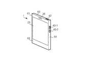
- FIG. 2 shows the appearance of the smartphone 1.
- the smartphone 1 has a housing 61 in the form of a thin rectangular parallelepiped, and the widest surface 62 of the housing 61 is provided with the display surface of the touch screen device 23.
- a speaker port 26 is provided on the upper side of the touch screen device 23.
- a main button 42 is provided on the upper surface 63 of the housing 61, and volume buttons 43-1 and 43-2 are provided on the side surface 64.
- the volume button 43-1 is a button to increase the volume
- the volume button 43-2 is a button to decrease the volume.
- the smartphone 1 is smaller than an ordinary smartphone, and for example, the widest surface 62 of the housing 61 is as large as a credit card.
- the thickness of the case 61 is, for example, a thickness which is not bulky even when put in a wallet or a business card holder.
- FIG. 3 shows a functional configuration realized by the smartphone 1.
- the smartphone 1 includes a battery power supply unit 101, an external communication unit 102, a touch screen unit 103, an event detection unit 104, a position measurement unit 105, and a mode control unit 106.
- the battery power supply unit 101 has a battery called a battery 32 shown in FIG. 1 and supplies power to each unit of the own device (smart phone 1).
- the battery power supply unit 101 is an example of the “power supply unit” in the present invention.
- the battery power supply unit 101 is realized by the power supply device 31 shown in FIG.
- the battery power source unit 101 is controlled by a mode control unit 106 described later, and supplies power to the function designated by the mode control unit 106 based on an operation on the button device 41 or the like.
- the external communication unit 102 is a function of communicating with an external device, and is an example of the “communication unit” in the present invention.
- the external communication unit 102 is realized by the communication device 14 shown in FIG.
- the external communication unit 102 When power is supplied from the battery power source unit 101, the external communication unit 102 operates in a standby state so that communication with an external device can be started any time.
- the external communication unit 102 receives a signal requesting connection, for example, transmitted from a base station of a mobile communication network in a standby state, and performs an operation to start a call, the external communication unit 102 performs connection processing, Start mobile communication via the station.
- the external communication unit 102 When the external communication unit 102 receives document data such as an e-mail or a post of SNS (Social Networking Service) in a standby state, the external communication unit 102 supplies the received document data to the processor 11, and the processor 11 supplies the received document data.
- the message is stored in the memory 12 or the like. The storage of the document data is automatically performed without the user performing an operation, and when the user views the document data later, the stored document data may be read and viewed without the communication. It can be done.
- the touch screen unit 103 includes a display unit 131 that displays an image, and a touch operation reception unit 132 that receives a touch operation, and performs image display and touch operation reception.
- the touch screen unit 103 is an example of the “touch screen unit” in the present invention.
- the display unit 131 is realized by the display 24 shown in FIG. 1, and the touch operation reception unit 132 is realized by the position detection sensor 25 shown in FIG.
- the touch operation is an operation performed by touching the surface of the display 24 of the touch screen device 23 shown in FIG. 1 with a finger or a touch pen (stylus pen) or the like. Since the touch screen unit 103 (display unit 131) displays an image on the display 24, which is an electrophoretic display device as described above, it consumes power to rewrite the displayed image, and maintains the rewritten image. Does not consume power.
- the event detection unit 104 is a function of detecting an event occurring in the own device (smart phone 1), and is an example of the “detection unit” in the present invention.
- the event referred to here is an event that can be detected by the operation of each part of the own apparatus, and is detected in order to rewrite an image described later.
- an event detected by the event detection unit 104 is referred to as an “image rewrite event”.
- the image rewriting event is an example of the "event" of the present invention.
- the event detection unit 104 detects, for example, a change in a numerical value of, for example, the order of "minutes" of the current time (for example, a change in which 1:05 becomes 1: 6) as an image rewriting event.
- the event detection unit 104 detects an image rewrite event by the operation of the position measurement unit 105.
- the position measurement unit 105 is a function of measuring the position of the own device (the smartphone 1), and is an example of the “measurement unit” in the present invention.
- the position measurement unit 105 is realized by the positioning device 15 shown in FIG.
- the event detection unit 104 detects, for example, measurement of a predetermined position by the position measurement unit 105 as an image rewriting event. A specific example of the predetermined position will be described later.
- the mode control unit 106 is a function that controls the own device (smart phone 1) to operate in a predetermined operation mode, and is an example of the “control unit” in the present invention.
- the operation mode is a rule (rule) which defines the function to be operated and the function not to be operated among the functions of the smartphone 1 and the operation to be performed if necessary.
- the mode control unit 106 controls operations in four operation modes in this embodiment.
- the four operation modes are “power off mode”, “first sleep mode”, “second sleep mode”, and “active mode”.
- mode control unit 106 determines whether power is supplied to each unit shown in FIG. 3, whether an image rewrite event is detected (whether an image rewrite event is detected), and the display operation of display unit 131. Control.
- the power supply control targets are the external communication unit 102, the position measurement unit 105, the display unit 131, and the touch operation reception unit 132. These functions are realized by the devices of the communication device 14, the positioning device 15, the display 24 and the position detection sensor 25.
- the mode control unit 106 designates a function of supplying power to the battery power supply unit 101
- the battery power supply unit 101 supplies power to a device that realizes the function.
- the mode control unit 106 thus controls the power supply of each function.
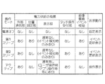
- the mode control unit 106 refers to an operation mode table (for example, stored in the storage 13) in which each operation mode, presence or absence of power supply to each unit, presence or absence of image rewrite event detection, and display operation are associated with each other. Perform this control.
- FIG. 4 shows an example of the operation mode table.
- the “external communication unit”, the “position measurement unit”, the “display unit”, and the “touch operation reception unit” each having the same function of FIG. 3
- the power supply to all is “none”
- the image rewriting event detection is also “none”
- the display operation is "fixed display”.
- the fixed display means that the display unit 131 does not change while the predetermined image is displayed.
- the “power off” mode is a mode in which the power of the smartphone 1 is turned off (the power is turned off), and a mode in which the smartphone 1 is not operated at all unless an operation to turn on the power is performed. It is.
- the mode control unit 106 causes the display unit 131 to rewrite the power-off image, which is a predetermined image for the power-off mode, before switching to the power-off mode.
- the power off image is fixedly displayed in the power off mode.
- the power-off image is, for example, a wallpaper image stored in advance by the provider of the smartphone 1 or an image set in advance for the user to perform fixed display in the power-off mode.
- the mode control unit 106 may display an image indicating a contact point at the time of loss as a power-off image.
- the contact point at the time of loss is information that can contact the owner of the smartphone 1 when contacting the contact point, and is, for example, the home telephone number or email address of the owner of the smartphone 1.
- the “first sleep” mode power is supplied to “external communication unit”, “position measurement unit”, “display unit”, and “touch operation reception unit” “yes”, “yes”, and “normally not “Temporarily”, “none”, “represented” is the image update event detection, and “event update display” is associated.
- the mode control unit 106 since the mode control unit 106 does not supply power to the touch operation receiving unit 132, the touch operation can not be received. Therefore, even if the touch screen device 23 is touched by mistake, for example, the smartphone 1 does not operate.
- the mode control unit 106 causes the external communication unit 102 to supply power
- the external communication unit 102 is in a standby state, and receives document data such as mobile communication connection request and e-mail, for example. It can be done.
- the event update display is a display for updating an image when the event detection unit 104 detects an image rewriting event.
- the power supply to the display unit 131 is “normally absent”, since the power is temporarily supplied only at the time of image updating, the power supply is represented as “temporarily available”.
- the mode control unit 106 causes the position measurement unit 105 to supply power.
- the event update display in the first sleep mode will be described using a specific example. For example, since the smartphone 1 is about the size of a credit card as described above, it can be put in an employee ID card case.
- the mode control unit 106 causes the display unit 131 to display an employee ID image representing an employee ID card of the user as a predetermined image.
- the mode control unit 106 displays an event update display using a position outside the user's company site as a predetermined position in the first sleep mode (in a state where the operation mode is set to the first sleep mode). I do.
- the event detection unit 104 when the measurement of the position outside the site of the company is detected as an image rewriting event by the event detection unit 104, that is, the user goes out of the site of the company
- an employee identification image including personal information is rewritten to, for example, a company emblem image representing just a company emblem.
- the company badge image is an example, and may be rewritten with wallpaper or the like set for each individual.
- the mode control unit 106 also performs event update display in the first sleep mode using the position of the user's company in the site as the predetermined position.
- the event detection unit 104 detects a measurement of a position on the premises of the company as an image rewriting event (that is, if the user enters the premises of the corporation)
- the mode control unit 106 In contrast to the case of going out, the company badge image is rewritten to the employee ID image.
- reception of the touch operation in the first sleep mode is for switching the operation mode to the active mode, and is not for operating the image displayed by the display unit 131.
- the mode control unit 106 supplies power to the external communication unit 102 and is in a standby state, so that the external communication unit 102 requests a connection for mobile communication and Document data such as e-mail can be received.
- the mode control unit 106 performs an event update display by using a change in the numerical value of the "minute" of the current time as an image rewriting event. Specifically, in the second sleep mode, the mode control unit 106 causes the display unit 131 to display the current time as a predetermined image, and rewrites the current time to a new current time every one minute. In the second sleep mode, the mode control unit 106 performs event update display using the reception of the connection request by the external communication unit 102 as an image rewriting event.
- the mode control unit 106 In the second sleep mode, when the connection request is received by the external communication unit 102 in the second sleep mode, the mode control unit 106 rewrites the image according to the received connection request as an incoming call image indicating that there is an incoming call, for example.
- the image corresponding to the connection request may be, for example, the phone number of the sender, the name of the sender, or a picture of the sender.
- the mode control unit 106 performs event update display by using the reception of the document data by the external communication unit 102 as an image rewriting event.
- the mode control unit 106 stores the received document data in the storage unit such as the storage 13 and responds to the received document data.
- a document reception image indicating reception of document data e.g., a character string image "mail has been received” or the like
- the image corresponding to the document data is not limited to this, and may be, for example, a character string image indicating the beginning of the document, a mail address of a sender of the document data, an SNS account, or the like.
- the mode control unit 106 since the measurement of the position is not used as an image rewriting event, the mode control unit 106 does not supply power to the position measurement unit 105.
- the above-described image rewriting event used for the event update display is merely an example, and the first sleep mode and the second sleep mode are not limited to the above-described example.
- the mode control unit 106 does not supply power to the position measurement unit 105 (note that power is supplied by functions other than the mode control unit 106 for use in applications). Is done). In the active mode, the mode control unit 106 causes the touch operation receiving unit 132 to supply power in order to perform operation display.
- the power supply to the display unit 131 is performed only when the image is rewritten by, for example, a user operation or an operation of an application. Also, even in the active mode, power is supplied to the external communication unit 102 and the device is in a standby state, so that the external communication unit 102 can receive document data such as a mobile communication connection request and an electronic mail.
- the mode control unit 106 performs switching of the above four operation modes with reference to a switching condition table (for example, stored in the storage 13) in which the switching source operation mode, the switching destination operation mode, and the switching conditions are associated. .
- FIG. 5 shows an example of the switching condition table.
- the switching source operation mode is the “power off” mode
- the switching destination operation mode is only the “active” mode
- the switching event is associated with “long press on main button”. ing.
- the mode control unit 106 switches to the “active” mode when the “main button long press” is performed in the “power off” mode.
- the mode control unit 106 switches to the "power off” mode when the "main button long press” is performed, or the “main button normal press” or When the "connection request / reception of document data" is made, the mode is switched to the "second sleep” mode.
- the "normal press” is an operation of pressing the button for a short time that is not determined to be a long press. Since the touch operation can not be accepted in the first sleep mode, the main button 42 that operates even when the operation of the external communication unit 102 to which power is supplied and the power supply is not performed is used as a switching event.
- the mode control unit 106 switches to the “power off” mode when the “main button long press” is performed, and the “main button normal press” is performed If it is recognized that the predetermined time has elapsed, the mode is switched to the "first sleep” mode, and if the "swipe operation” is performed, the mode is switched to the "active” mode. Since the touch operation is accepted in the second sleep mode, a swipe operation (an operation of moving the touch position in any direction from an arbitrary point on the display surface) is used as a switching event.
- the mode control unit 106 switches to the "power off” mode when the "main button long press” is performed, and the “main button normal press” is performed or the "fixed time Switch to the "second sleep” mode when the "elapsed time” is recognized.
- the active mode is switched from the active mode to the second sleep mode when a predetermined time elapses and to the first sleep mode when the predetermined time elapses.
- the first sleep mode and the second sleep mode can be forcibly switched.
- the call reception image is displayed in the event update display after switching to the second sleep mode. If a swipe operation is performed in this state, the mode is switched to the active mode, so that a call can be started by operating, for example, a call start button displayed by the telephone application.
- the mode control unit 106 switches the operation mode of the own device when the switching condition indicating whether to switch the operation mode is satisfied. For example, the mode control unit 106 determines that the switching condition is satisfied when the main button 42 is normally pressed in the second sleep mode, or when a predetermined time elapses, and switches to the first sleep mode.
- the first sleep mode is an operation mode in which supply of power from the battery power supply unit 101 to the external communication unit 102 is performed.
- the first sleep mode is an example of the “first operation mode” in the present invention.
- the switching condition used in this case is an example of the "first condition" in the present invention.
- the first sleep mode is an operation mode in which power is not supplied from the battery power supply unit 101 to the touch screen unit 103 in a state where an image is maintained by the touch screen unit 103 (state in which event update display is performed). It is.
- the mode control unit 106 temporarily supplies power from the battery power supply unit 101 to the touch screen unit 103. Specifically, the mode control unit 106 causes the battery power supply unit 101 to temporarily supply power to the touch screen unit 103, and the image displayed on the touch screen unit 103 is an image according to the detected image rewriting event. Make it rewrite.
- the mode control unit 106 rewrites the employee ID image into a company badge image (an image corresponding to the image rewriting event) when an image rewriting event to measure the position outside the company's site is detected, and the mode control unit 106 When an image rewriting event of measuring the position of is detected, the company badge image is rewritten to an employee ID image (an image corresponding to the image rewriting event).
- the mode control unit 106 receives the touch screen from the battery power supply unit 101.
- the power is temporarily supplied to the unit 103, and the image displayed on the touch screen unit 103 is rewritten to an image (in the above example, a company emblem image or an employee ID card image) corresponding to the position measured by the position measurement unit 105. .
- the second sleep mode is an example of the “second operation mode” in the present invention, and the switching condition used for switching to the second sleep mode is an example of the “second condition” in the present invention.
- the second sleep mode is a state in which an image is maintained by the touch screen unit 103 (a state in which an event update display is performed), and the supply of power from the battery power supply unit 101 to the touch screen unit 103 is performed.
- an operation mode in which supply of power from the battery power supply unit 101 to the external communication unit 102 is performed.
- the mode control unit 106 determines that the switching condition is satisfied, and the operation of the own device Switch the mode to power off mode.
- the power-off mode is an operation mode in which power is not supplied from the battery power supply unit 101 to any part of the apparatus itself.
- the power off mode is an example of the “third operation mode” in the present invention.
- the switching condition used in this case is an example of the "third condition" in the present invention.
- the mode control unit 106 switches the apparatus to the power-off mode. Further, also in the second sleep mode and the active mode, the mode control unit 106 switches the operation mode of the own device to those operation modes when the switching conditions shown in FIG. 5 are satisfied.
- the smartphone 1 performs mode switching processing to switch the operation mode based on the above configuration.
- FIG. 6 shows an example of the operation procedure in the mode switching process. This operation procedure is constantly repeated, for example, while the smartphone 1 is operating.
- the smartphone 1 determines whether or not the operation mode switching condition is satisfied based on the current operation mode and the switching condition table shown in FIG. 5 (step S11).
- the smartphone 1 repeats the operation of step S11 until it determines that the switching condition is satisfied (YES). If the smartphone 1 (mode control unit 106) determines that the switching condition is satisfied (YES), the smartphone 1 (mode control unit 106) determines what the operation mode of the switching destination is (step S12). If the smartphone 1 (mode control unit 106) determines that the switching destination is the power off mode, first, the displayed image is rewritten to the power off image (step S21).
- step S21 the smartphone 1 (mode control unit 106) stops the power supply to each unit of the own device (step S22), and ends this operation procedure.
- the power-off image rewritten in step S21 is in a non-rewritable state, that is, a fixed display state as long as the power-off mode continues.
- step S12 determines in step S12 that the switching destination is the first sleep mode
- the battery power supply unit 101 causes the external communication unit 102 and the position measurement unit 105 to supply power (step S31). If power is already supplied to these functions, the state is maintained.
- the smartphone 1 measures the position of the own device (step S32).
- the smartphone 1 displays an image corresponding to the measured position of the image displayed on the display unit 131 (in the above example, if the position outside the site of the company is measured, the company badge image If the position on the premises of the company is measured, it is rewritten to an employee ID image (step S33). Then, the smartphone 1 (mode control unit 106) starts the process of the above-described event update display (step S34), and ends the operation procedure. Details of the process of the event update display will be described later with reference to another diagram.
- step S12 When the smartphone 1 (mode control unit 106) determines in step S12 that the switching destination is the second sleep mode, first, the battery power supply unit 101 causes the external communication unit 102 and the touch operation reception unit 132 to supply power (step S41). Subsequently, the smartphone 1 (mode control unit 106) causes the display unit 131 to display an image of the current time (step S42). Then, the smartphone 1 (mode control unit 106) starts the process of the event update display (step S43), and ends the operation procedure.
- step S12 When the smartphone 1 (mode control unit 106) determines in step S12 that the switching destination is the active mode, first, the battery power supply unit 101 causes the external communication unit 102 and the touch operation reception unit 132 to supply power (step S51) . Subsequently, the smartphone 1 (mode control unit 106) restores, for example, the display state at the end of the previous active mode (step S52). Then, the smartphone 1 starts the process of the operation display for displaying the image according to the operation of the user (step S53), and ends the operation procedure.
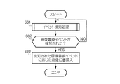
- FIG. 7 shows an example of an operation procedure in the event update display process.
- the smartphone 1 event detection unit 1014 performs an event detection process that attempts to detect an image rewriting event (such as measurement of a predetermined position) (step S61).
- the smartphone 1 mode control unit 106) determines whether or not the image rewriting event is detected in step S61 (step S62), and when it is determined that it is not detected (NO), the process returns to step S61 and performs operation .
- step S62 If the smartphone 1 (mode control unit 106) determines that (YES) is detected in step S62, an image corresponding to the detected image rewriting event (an image of the current time described above, a company emblem image or an employee Etc.) (step S63), and this operation procedure ends.
- the smartphone 1 repeatedly performs the operation procedure shown in FIG. 7 while operating in the first sleep mode and the second sleep mode.
- the fixed display is performed as described above even in the power off mode. In this way, even when power is hardly consumed, it is possible to convey some information (for example, contact information when lost) to the user by the image (power-off image) displayed on the smartphone. Further, in the present embodiment, in the sleep mode (the first sleep mode and the second sleep mode) in which the consumption of power is suppressed as compared to the active mode, an image is displayed while displaying the power saving that basically does not rewrite the image. When a rewrite event is detected, event update display is performed.
- this event update display since power is consumed only at the time of image rewriting, it is possible to convey information (for example, current time etc.) that changes with time while continuing to suppress the power consumption described above. Further, in the present embodiment, measurement of a predetermined position of the smartphone 1 is used as an image rewriting event in the first sleep mode. Thereby, while continuing the suppression of the power consumption described above, it is possible to display a more desirable image at each position where the user is present, as in the example of the photo award image and the company badge image described above.
- the touch operation is not accepted in the first sleep mode.
- the smartphone 1 is held by a finger like a card and held in a chest pocket or the like, it operates unintentionally and an image showing power saving display (for example, employee ID image or company emblem image etc. Power saving display can be used by ensuring that the) does not disappear.
- an image showing power saving display for example, employee ID image or company emblem image etc. Power saving display can be used by ensuring that the) does not disappear.
- the button device 41 may have operators other than the main button 42 and the volume button 43 described above.
- the button device 41 may include a lock button, a home button, a back button, a history button, and the like.
- the smartphone may include an operator that determines that the button is not pressed by the touch sensor but the touch sensor is pressed.
- FIG. 8 shows a functional configuration realized by the smartphone 1a of the present modification.
- the smartphone 1 a includes a user operation receiving unit 107 in addition to the units illustrated in FIG. 3.
- the user operation reception unit 107 is a function of receiving a user operation, and is an example of the “operation reception unit” in the present invention.
- the user operation reception unit 107 is realized by, for example, the button device 41 illustrated in FIG. 1 and receives an operation on the volume button 43.
- the user operation reception unit 107 notifies the event detection unit 104 to that effect.
- the event detection unit 104 detects the reception of an operation on the volume button 43 by the user operation reception unit 107 as an image rewriting event.
- the mode control unit 106 receives the touch screen unit from the battery power supply unit 101. Power is temporarily supplied to the image processing unit 103 and the image displayed on the touch screen unit 103 is rewritten to an image corresponding to the detected operation.
- the employee ID image described in the embodiment is associated with the operation to the volume button 43-1
- the company emblem image is associated with the operation to the volume button 43-2.
- the mode control unit 106 receives an operation on the volume button 43-1
- the image other than the employee ID card image is displayed on the display unit 131
- the image in the display is displayed as the volume button 43-1.
- the operation to be detected is not limited to the above example, and any operation may be used as long as it is an operation other than the touch operation received by the touch screen unit 103 to which power is not supplied in the first sleep mode.
- the user when there are a plurality of images displayed by the event update display in the first sleep mode, the user can switch to an image that he / she wants to display at any time.
- the image rewriting event is not limited to the one described above.
- only measurement of a predetermined position is used as an image rewriting event in the first sleep mode.
- the mode control unit 106 performs event update display using reception of a connection request and reception of document data used as a condition for switching to the second sleep mode in the embodiment as an image rewriting event in the first sleep mode. May be
- the mode control unit 106 causes the battery power supply unit 101 to temporarily supply power to the touch screen unit 103, and the touch operation is performed.
- the image displayed on the screen unit 103 is rewritten to an image according to the received connection request (for example, an incoming image indicating that an incoming call has been received).
- the mode control unit 106 stores the received document data in the storage unit such as the storage 13. At the same time, the mode control unit 106 causes the battery power supply unit 101 to temporarily supply power to the touch screen unit 103, and an image displayed on the touch screen unit 103 is an image corresponding to the received document data (for example, a document The document reception image (indicating reception of data) is rewritten.
- the mode control unit 106 uses reception of a connection request and reception of document data as a switching condition to the second sleep mode, the event update display in the first sleep mode can not be performed. Do not use. By doing so, the mode control unit 106 can display the above-described incoming image or document reception image while maintaining the first sleep mode.
- the switching condition from the first sleep mode to the active mode is not determined, but in this modification, for example, the normal pressing of the main button 42 is switched to the active mode instead of the switching condition to the second sleep mode. It may be defined as a condition. Alternatively, normal pressing of the main button 42 may be left as a switching condition to the second sleep mode, and for example, double pressing of the main button 42 may be defined as a switching condition to the active mode.
- the user who has seen the event update display in the first sleep mode starts a call or browses the received document data, as compared with the case where the switching condition from the first sleep mode to the active mode is not determined. It is possible to reduce time and effort. Further, in the embodiment, when the connection request is received and the document data is received, the second sleep mode is always switched.
- the user can select to maintain the first sleep mode by performing the above-described event update display in the first sleep mode.
- the mode control unit 106 may perform, for example, an event update display indicating the current time in the first sleep mode, or measure the predetermined position in the second sleep mode as an image rewriting event.
- the event update display used may be performed.
- the mode control unit 106 displays an event update display (for example, displaying a character string image indicating that a meeting starts before the time of the meeting) that uses a predetermined time as an image rewriting event. Good.
- the smartphone since the smartphone is so small that it can be put in the chest pocket, for example, a heart rate sensor is provided, and the mode control unit 106 generates an image that the user's heart rate is abnormal in the first sleep mode or the second sleep mode.
- An event update display used as a rewrite event may be performed.
- the mode control unit 106 displays, for example, a history of a heart rate at which an abnormality has occurred or a character string indicating that an abnormality is to be warned.
- any event may be used as the image rewriting event as long as it is possible to detect the occurrence of the event by the function of the smartphone and to display the image according to the event.
- the event update display does not have to be necessarily performed in the first sleep mode or the second sleep mode, and a fixed display may be performed as in the power off mode. In that case, the amount of power consumption can be further reduced compared to the event update display.
- the image corresponding to the position measured by the position measurement unit 105 is not limited to the one described in the embodiment (such as a company badge image or an employee ID card image).
- a reader of one-time password is a door It is assumed that it is provided.
- the mode control unit 106 may perform the event update display using the measurement of the position indicating the high security floor or the measurement of the position indicating the high security floor as an image rewriting event. Although both floors are inside a building, the position of each floor can be measured using WiFi positioning. When the measurement of the position indicating the high security floor is detected as an image rewriting event, the mode control unit 106 rewrites the image displayed on the touch screen unit 103 with an image (for example, a barcode) indicating a one-time password.
- an image for example, a barcode
- the mode control unit 106 rewrites the image displayed on the touch screen unit 103 into an image not including the one-time password.
- an image showing a one-time password is displayed even if the user does not operate the smartphone, so that the door can be opened compared to the case where the image is displayed by the user's operation. It is possible to reduce the time and effort.
- the longer the period for displaying the image showing the one-time password the higher the risk of leaking the one-time password to a third party.
- this modification when moving to the normal floor, an image not including the one-time password is displayed, so there is a risk of leakage of the one-time password as compared to the case where the image showing the one-time password is displayed on the normal floor. It can be lowered.
- the mode control unit 106 displays an event update display that rewrites the image displayed on the display unit 131 into a code image that can be used by the store when an image rewriting event to measure the position of the store is detected. I do.
- the mode control unit 106 causes the event update display to rewrite the image displayed on the display unit 131 into an image not including the code image when an image rewriting event to measure the position away from the store is detected. Do. As a result, compared with the case where these event update displays are not performed, it is possible to reduce the time and effort when performing the settlement in the above-mentioned store, and to reduce the risk of code image leakage and abuse. Can.
- the event update display of this modification may be performed in any of the first sleep mode and the second sleep mode.
- the power off image may be different depending on the situation.
- the mode control unit 106 has a condition that “the battery is exhausted” (hereinafter referred to as “long press condition”) satisfied by long press of the main button 42 shown in FIG. And a plurality of switching conditions including switching conditions (hereinafter referred to as “battery depletion conditions”) satisfied by “1.
- This battery depletion condition is an example of the “fourth condition” in the present invention.
- the mode control unit 106 switches the operation mode to the power off mode when any of the plurality of switching conditions (long press condition and battery dead condition) described above is satisfied. At this time, the mode control unit 106 rewrites the image displayed on the touch screen unit 103 into an image according to whether the satisfied switching condition is the battery depletion condition or not, and then the operation of the own device is performed. Switch the mode to power off mode.
- the mode control unit 106 performs fixed display with the wallpaper set by the user as the power-off image, and when the battery depletion condition is satisfied, the smartphone 1 is lost. Fixed display is performed with the image showing the contact point at the time as the power off image. Since the smartphone 1 is basically used every day, it is always charged and the battery is not likely to run out.
- the owner when the power is turned off by the long press on the main button 42, the owner often uses the smartphone 1.
- the long press condition which is a switching condition other than the battery running out condition
- another power off image is displayed in a fixed manner. Compared with the case where the personal information of the owner is less likely to be known to others.
- the functional configuration of the smartphone is not limited to those shown in FIG. 3 and FIG.
- a plurality of functional blocks shown in FIG. 3 may be integrated into one functional block.
- part of the functions may be separated to provide a new function block.
- a part of the operations may be performed by another functional block.
- the event detection unit 104 and the mode control unit 106 may be integrated into one function that performs both detection of an event and control of an operation mode. Further, for example, the control of the power supply destination performed by the mode control unit 106 and the event update display may be performed by different functions. In any case, functions equivalent to the functions shown in FIG. 3 and FIG. 8 may be realized in the entire functional configuration.
- a display device of electrophoresis type is used, but not limited to this, for example, a reflection type liquid crystal using cholesteric liquid crystal which maintains the direction of liquid crystal molecules even if the voltage is cut.
- a display may be used.
- the display device of the present invention consumes power for rewriting an image to be displayed and does not consume power for maintaining the rewritten image, thereby maintaining the convenience of communication. Power saving display can be utilized.
- the present invention can also be applied to a display device provided with a touch screen unit (a touch screen unit provided with a backlight liquid crystal display) in which rewriting consumes power to maintain an image.
- the battery power supply unit 101 can separately supply power to the display unit 131 and the touch operation receiving unit 132 of the touch screen unit.
- the mode control unit 106 controls the battery power supply unit 101 not to supply power to the display unit 131 and the external communication unit 102 and not to supply power to the touch operation reception unit 132.
- the mode control unit 106 does not supply power for the touch operation from the battery power supply unit 101 in a state where the image displayed by the touch screen unit is maintained, and the external communication unit 102 from the battery power supply unit 101.
- the operation mode in which power is supplied to the device is switched to the first sleep mode to switch the device itself.
- the present invention is applicable not only to a smartphone but also to display devices such as a tablet terminal, an electronic book terminal and a notebook computer.
- the present invention can be applied to the display device described in the above-described modified example as long as it realizes each function shown in FIG. 3 or FIG.
- the present invention can be understood as an information processing method for realizing processing executed by the display device as well as such a display device, and also as a program for causing a computer that controls the display device to function. Can be caught.
- This program may be provided in the form of a recording medium such as an optical disc storing the program, or may be downloaded to a computer via a network such as the Internet, provided in a form such as installing it and making it available. It may be done.
- the input and output information and the like may be stored in a specific place (for example, a memory) or may be managed by a management table. Information to be input or output may be overwritten, updated or added. The output information etc. may be deleted. The input information or the like may be transmitted to another device.
- Software Software may be called software, firmware, middleware, microcode, hardware description language, or any other name. Instructions, instruction sets, codes, code segments, program codes, programs Should be interpreted broadly to mean: subprograms, software modules, applications, software applications, software packages, routines, subroutines, objects, executables, threads of execution, procedures, functions, etc.
- software, instructions, etc. may be sent and received via a transmission medium.
- software may use a wireline technology such as coaxial cable, fiber optic cable, twisted pair and digital subscriber line (DSL) and / or a website, server or other using wireless technology such as infrared, radio and microwave When transmitted from a remote source, these wired and / or wireless technologies are included within the definition of transmission medium.
- wireline technology such as coaxial cable, fiber optic cable, twisted pair and digital subscriber line (DSL) and / or a website, server or other using wireless technology such as infrared, radio and microwave
- notification of predetermined information is not limited to what is explicitly performed, but is performed by implicit (for example, not notifying of the predetermined information) It is also good.
Landscapes
- Engineering & Computer Science (AREA)
- Theoretical Computer Science (AREA)
- General Engineering & Computer Science (AREA)
- Physics & Mathematics (AREA)
- General Physics & Mathematics (AREA)
- Human Computer Interaction (AREA)
- Signal Processing (AREA)
- Computer Networks & Wireless Communication (AREA)
- Telephone Function (AREA)
- Power Sources (AREA)
- Control Of Indicators Other Than Cathode Ray Tubes (AREA)
- Controls And Circuits For Display Device (AREA)
- User Interface Of Digital Computer (AREA)
Abstract
バッテリー電源部101は、自装置の各部に電力を供給する。外部通信部102は、外部装置と通信を行う。タッチスクリーン部103は、画像の表示及びタッチ操作の受け付けを行う。モード制御部106は、自装置が所定の動作モードで動作するように制御する。モード制御部106は、例えば、バッテリー電源部101から外部通信部102への電力の供給が行われ、且つ、タッチスクリーン部103により画像が維持された状態でバッテリー電源部101からタッチスクリーン部103への電力の供給が行われない動作モードである第1スリープモードで自装置を動作させる。
Description
本発明は、ユーザインターフェースの技術に関する。
特許文献1には、液晶パネルと電子ペーパ(電源切断後も画像が消えない特徴を持った表示媒体)とを同一の電極基板上に積層して構成し、スリープモードに移行して表示操作パネルの電源がオフにされたときに、電子ペーパにスリープ機能動作時のデフォルト表示画面を表示させる技術が開示されている。
電子ペーパでは、タッチスクリーン部に表示した画像を前述したように電力を消費しなくても維持する技術が用いられることが多い。そのようにタッチスクリーン部の電力消費を抑える技術をスマートフォンのような通信機能を有する表示装置に適用する場合、省電力だけでなく通信の利便性が犠牲にならないようにすることが望ましい。
そこで、本発明は、通信の利便性を保ちつつタッチスクリーン部の電力消費を抑えることを目的とする。
そこで、本発明は、通信の利便性を保ちつつタッチスクリーン部の電力消費を抑えることを目的とする。
上記目的を達成するために、本発明は、自装置の各部に電力を供給する電源部と、通信を行う通信部と、表示及びタッチ操作の受け付けを行うタッチスクリーン部と、第1の条件が満たされた場合に、前記タッチスクリーン部により表示された画像が維持された状態で前記電源部から前記タッチ操作のための電力が供給されず、且つ、前記電源部から前記通信部への電力の供給が行われる動作モードである第1動作モードに自装置を切り替える制御部とを備える表示装置を提供する。
また、前記タッチスクリーン部は、表示する画像の書き換えには電力を消費し、書き換えた画像の維持には電力を消費せず、前記制御部は、前記タッチスクリーン部により画像が維持された状態で前記電源部から前記タッチスクリーン部への電力の供給が行われない動作モードを前記第1動作モードとして自装置の切り替えを行ってもよい。
また、自装置で発生するイベントを検知する検知部を備え、前記制御部は、前記第1動作モードにおいて、前記検知部によりイベントが検知された場合に、前記電源部から前記タッチスクリーン部に一時的に電力を供給させ、前記タッチスクリーン部に表示されている画像を当該イベントに応じた画像に書き換えさせてもよい。
さらに、自装置の位置を測定する測定部を備え、前記検知部は前記測定部による所定の位置の測定を前記イベントとして検知し、前記制御部は、前記第1動作モードにおいて、前記検知部により前記測定部による所定の位置の測定が検知された場合に、前記電源部から前記タッチスクリーン部に一時的に電力を供給させ、前記タッチスクリーン部に表示されている画像を当該位置に応じた画像に書き換えさせてもよい。
また、ユーザの操作を受け付ける操作受付部を備え、前記検知部は前記操作受付部による操作の受け付けを検知し、前記制御部は、前記第1動作モードにおいて、前記検知部により前記操作受付部による操作の受け付けが検知された場合に、前記電源部から前記タッチスクリーン部に一時的に電力を供給させ、前記タッチスクリーン部に表示されている画像を当該操作に応じた画像に書き換えさせてもよい。
さらに、前記制御部は、前記第1動作モードにおいて、前記通信部によりデータが受信された場合に、前記電源部から前記タッチスクリーン部に一時的に電力を供給させ、前記タッチスクリーン部に表示されている画像を前記通信部により受信されたデータに応じた画像に書き換えさせてもよい。
また、前記制御部は、第2の条件が満たされた場合に、前記電源部から前記タッチスクリーン部及び前記通信部への電力の供給が行われる動作モードである第2動作モードに自装置を切り替えてもよい。
また、前記制御部は、第2の条件が満たされた場合に、前記電源部から前記タッチスクリーン部及び前記通信部への電力の供給が行われる動作モードである第2動作モードに自装置を切り替えてもよい。
また、前記制御部は、第3の条件が満たされた場合に、前記タッチスクリーン部に表示されている画像を所定の画像に書き換えさせた後、前記電源部から自装置の各部のいずれにも電力が供給されない動作モードである第3動作モードに自装置を切り替えてもよい。
さらに、前記電源部は電池を有し、前記第3の条件には、前記電池が切れた場合に満たされる第4の条件を含む複数の条件があり、前記制御部は、前記複数の条件のいずれかが満たされた場合に、前記タッチスクリーン部に表示されている画像を、当該満たされた条件が前記第4の条件であるか否かに応じた画像に書き換えさせた後、自装置を前記第3動作モードに切り替えてもよい。
また、本発明は、電源部と、通信部と、タッチスクリーン部とを備える表示装置の表示方法であって、第1の条件が満たされた場合に、前記タッチスクリーン部により表示された画像が維持された状態で前記タッチスクリーン部に対するタッチ操作のための電力が前記電源部から供給されず、且つ、前記電源部から前記通信部への電力の供給が行われる動作モードである第1動作モードに自装置を切り替えるステップを含む表示方法を提供する。
本発明によれば、通信の利便性を保ちつつタッチスクリーン部の電力消費を抑えることができる。
1…スマートフォン、11…プロセッサ、12…メモリ、13…ストレージ、14…通信装置、15…測位装置、21…入力装置、22…出力装置、23…タッチスクリーン装置、24…ディスプレイ、25…位置検出センサ、31…電力供給装置、32…バッテリー、41…ボタン装置、42…メインボタン、43…音量ボタン、51…バス、52…電力供給回路、101…バッテリー電源部、102…外部通信部、103…タッチスクリーン部、104…イベント検知部、105…位置測定部、106…モード制御部、107…ユーザ操作受付部、131…表示部、132…タッチ操作受付部。
[1]実施例
図1は実施例に係るスマートフォン1のハードウェア構成を表す。スマートフォン1は、プロセッサ11と、メモリ12と、ストレージ13と、通信装置14と、測位装置15と、入力装置21と、出力装置22と、電力供給装置31と、ボタン装置41と、バス51と、電力供給回路52という各装置を備えるコンピュータである。
図1は実施例に係るスマートフォン1のハードウェア構成を表す。スマートフォン1は、プロセッサ11と、メモリ12と、ストレージ13と、通信装置14と、測位装置15と、入力装置21と、出力装置22と、電力供給装置31と、ボタン装置41と、バス51と、電力供給回路52という各装置を備えるコンピュータである。
なお、ここでいう「装置」という文言は、回路、デバイス及びユニット等に読み替えることができる。また、各装置は、1つ又は複数含まれていてもよいし、一部の装置が含まれていなくてもよい。プロセッサ11は、例えば、オペレーティングシステムを動作させてコンピュータ全体を制御する。プロセッサ11は、周辺装置とのインターフェース、制御装置、演算装置、レジスタなどを含む中央処理装置(CPU:Central Processing Unit)で構成されてもよい。
また、プロセッサ11は、内蔵時計を備えており、その内蔵時計から現在の日付及び時刻を取得することができる。また、プロセッサ11は、OS(Operating System:オペレーティングシステム)及び各種のアプリケーション(アプリ)を含むプログラム(プログラムコード)、ソフトウェアモジュール及びデータ等を、ストレージ13及び/又は通信装置14からメモリ12に読み出す。
プロセッサ11は、読み出したOS等に従って各種の処理を実行する。各種処理を実行するプロセッサ11は1つでもよいし、2以上であってもよく、2以上のプロセッサ11は、同時又は逐次に各種処理を実行してもよい。また、プロセッサ11は、1以上のチップで実装されてもよい。プログラムは、電気通信回線を介してネットワークから送信されてもよい。
メモリ12は、コンピュータ読み取り可能な記録媒体であり、例えば、ROM(Read Only Memory)、EPROM(Erasable Programmable ROM)、EEPROM(Electrically Erasable Programmable ROM)及びRAM(Random Access Memory)等の少なくとも1つで構成されてもよい。メモリ12は、レジスタ、キャッシュ及びメインメモリ(主記憶装置)等と呼ばれてもよい。メモリ12は、前述したプログラム(プログラムコード)、ソフトウェアモジュール及びデータ等を保存することができる。
ストレージ13は、コンピュータが読み取り可能な記録媒体であり、例えば、ハードディスクドライブ、フレキシブルディスク、フラッシュメモリ(例えば、カード、スティック、キードライブ)、磁気ストリップなどの少なくとも1つで構成されてもよい。ストレージ13は、補助記憶装置と呼ばれてもよい。上述の記憶媒体は、例えば、メモリ12及び/又はストレージ13を含むデータベース、サーバその他の適切な媒体であってもよい。
通信装置14は、有線及び/又は無線ネットワークを介してコンピュータ間の通信を行うためのデバイス(送受信デバイス)であり、例えばネットワークデバイス、ネットワークコントローラ、ネットワークカード、通信モジュールなどともいう。通信装置14は、本実施例では、移動体通信及び無線LAN(Local Area Network)通信を含む無線通信を行う。
測位装置15は、自装置(スマートフォン1)の位置を測定するデバイスであり、例えばGPS(Global Positioning System)の技術を用いて自装置の位置を測定する。なお、位置の測定方法は、GPSに限らず、例えば基地局又は無線LANのアクセスポイントとの通信強度を利用して位置を測定する基地局測位又はWiFi測位等の測定方法が用いられてもよい。
入力装置21は、外部からの入力を受け付ける入力デバイス(例えば、マイクロフォン、スイッチ、ボタン、センサなど)である。出力装置22は、外部への出力を実施する出力デバイス(例えば、ディスプレイ、スピーカ、LEDランプなど)である。スマートフォン1においては、入力装置21及び出力装置22は、一体となってタッチスクリーン装置23を構成している。
タッチスクリーン装置23は、画像を表示する出力デバイスであると共に、ユーザの操作を受け付ける入力デバイスである。タッチスクリーン装置23は、ディスプレイ24と、位置検出センサ25とを備える。ディスプレイ24は、画像を表示させるデバイスである。ディスプレイ24は、本実施例では、電気泳動方式の表示装置であり、電力を消費して表示させる画像を書き換え、書き換えた後の画像は電力を消費することなく維持する。
位置検出センサ25は、ディスプレイ24上でユーザがタッチした位置(タッチ位置)を検出するデバイスである。電力供給装置31は、電力を蓄積するバッテリー32を備え、そのバッテリー32が蓄積した電力を自装置(スマートフォン1)の各部に供給するデバイスである。ボタン装置41は、メインボタン42及び音量ボタン43を含む操作子を備え、それらの操作子への操作を受け付ける。
プロセッサ11等の各装置は、バス51を介して互いにアクセス可能となっている。バス51は、情報を通信するための配線である。バス51は、単一のバスで構成されてもよいし、装置間で異なるバスで構成されてもよい。また、プロセッサ11等の各装置には、電力供給回路52を介して電力供給装置31から電力が供給される。電力供給回路52は、電力供給装置31に接続され、各装置に必要な電力を供給する回路である。
メインボタン42を除く各装置はいずれも電力供給装置31から電力供給回路52を介して電力が供給されていなければ動作しない。メインボタン42は、いわゆる電源ボタンとして用いられる操作子であり、例えばバッテリー32の電力が直接供給されており、電力供給装置31及び電力供給回路52を介してボタン装置41に電力が供給されていなくても動作する。
本実施例では、メインボタン42は、電力供給装置31による電力供給がされていない状態で長押しの操作が行われると、電力供給を開始させることを示す電源ON信号を電力供給装置31に供給する。電力供給装置31は、この電源ON信号が供給されると、プロセッサ11等への電力供給を開始する。なお、メインボタン42は、電源ボタン以外の用途でも用いられる(詳細は後述する)。音量ボタン43は、主として音量を増減させる際に用いられる操作子であり、ボタン装置41に電力が供給されているときに動作する。
なお、スマートフォン1は、マイクロプロセッサ、デジタル信号プロセッサ(DSP:Digital Signal Processor)、ASIC(Application Specific Integrated Circuit)、PLD(Programmable Logic Device)、及び、FPGA(Field Programmable Gate Array)等のハードウェアを含んで構成されてもよく、当該ハードウェアにより、各機能ブロックの一部又は全てが実現されてもよい。例えば、プロセッサ11は、これらのハードウェアの少なくとも1つで実装されてもよい。
図2はスマートフォン1の外観を表す。スマートフォン1は、薄い直方体の形をした筐体61を有しており、筐体61の最も広い面62にタッチスクリーン装置23の表示面が設けられている。タッチスクリーン装置23の上側にはスピーカ口26が設けられている。筐体61の上面63にはメインボタン42が設けられており、側面64には音量ボタン43-1及び43-2が設けられている。
例えば音量ボタン43-1は音量を上げるボタン、音量ボタン43-2は音量を下げるボタンである。スマートフォン1は、通常のスマートフォンに比べて小型に作られており、例えば筐体61の最も広い面62でもクレジットカード程度の大きさとなっている。また、筐体61の厚さも、例えば財布又は名刺入れ等に入れてもかさばらない程度の厚さとなっている。
スマートフォン1のプロセッサ11がプログラムを実行して各部を制御することで以下に述べる機能群が実現される。
図3はスマートフォン1が実現する機能構成を表す。スマートフォン1は、バッテリー電源部101と、外部通信部102と、タッチスクリーン部103と、イベント検知部104と、位置測定部105と、モード制御部106とを備える。
図3はスマートフォン1が実現する機能構成を表す。スマートフォン1は、バッテリー電源部101と、外部通信部102と、タッチスクリーン部103と、イベント検知部104と、位置測定部105と、モード制御部106とを備える。
バッテリー電源部101は、図1に表すバッテリー32という電池を有し、自装置(スマートフォン1)の各部に電力を供給する。バッテリー電源部101は本発明の「電源部」の一例である。バッテリー電源部101は図1に表す電力供給装置31により実現される。バッテリー電源部101は、後述するモード制御部106によって制御され、ボタン装置41への操作等に基づいてモード制御部106が指定した機能に対して電力を供給する。
外部通信部102は、外部装置と通信を行う機能であり、本発明の「通信部」の一例である。外部通信部102は図1に表す通信装置14によって実現される。外部通信部102は、バッテリー電源部101から電力が供給されると、いつでも外部装置との通信を開始できるように待機状態で動作する。外部通信部102は、待機状態のときに例えば移動体通信網の基地局から発信された接続を要求する信号を受信して、ユーザが通話を開始する操作を行うと、接続処理を行い、基地局を介した移動体通信を開始する。
また、外部通信部102は、待機状態のときに電子メール又はSNS(Social Networking Service)の投稿等の文書データを受信すると、受信した文書データをプロセッサ11に供給し、プロセッサ11が、供給されたメッセージをメモリ12等に記憶させる。この文書データの記憶は、ユーザが操作を行わなくても自動的に行われ、ユーザが後から文書データを見る際には、通信を行わなくても記憶された文書データを読み出して見ることができるようになっている。
タッチスクリーン部103は、画像を表示する表示部131と、タッチ操作を受け付けるタッチ操作受付部132とを備え、画像の表示及びタッチ操作の受け付けを行う。タッチスクリーン部103は本発明の「タッチスクリーン部」の一例である。表示部131は図1に表すディスプレイ24によって実現され、タッチ操作受付部132は図1に表す位置検出センサ25によって実現される。
タッチ操作とは、指又はタッチペン(スタイラスペン)等で図1に表すタッチスクリーン装置23のディスプレイ24の表面をタッチして行う操作のことである。タッチスクリーン部103(表示部131)は、上記のとおり電気泳動方式の表示装置であるディスプレイ24に画像を表示するので、表示する画像の書き換えには電力を消費し、書き換えた画像の維持には電力を消費しない。
イベント検知部104は、自装置(スマートフォン1)で発生するイベントを検知する機能であり、本発明の「検知部」の一例である。ここでいうイベントとは、自装置の各部の動作により検知可能な事象であり、後述する画像の書き換えを行うために検知される。以下ではイベント検知部104が検知するイベントのことを「画像書換イベント」という。画像書換イベントは本発明の「イベント」の一例である。イベント検知部104は、例えば、現在時刻のうちの例えば「分」の位の数値の変化(例えば1時5分が1時6分になる変化)を画像書換イベントとして検知する。
また、イベント検知部104は、本実施例では、位置測定部105の動作により画像書換イベントを検知する。位置測定部105は、自装置(スマートフォン1)の位置を測定する機能であり、本発明の「測定部」の一例である。位置測定部105は図1に表す測位装置15により実現される。イベント検知部104は、例えば位置測定部105による所定の位置の測定を画像書換イベントとして検知する。所定の位置の具体例については後述する。
モード制御部106は、自装置(スマートフォン1)が所定の動作モードで動作するように制御する機能であり、本発明の「制御部」の一例である。動作モードとは、スマートフォン1が備える各機能のうち動作させる機能及び動作させない機能を定め、動作させる機能については必要ならそれが行うべき動作を定めた規則(ルール)のことである。モード制御部106は、本実施例では、4つの動作モードでの動作を制御する。4つの動作モードとは、「電源オフモード」と、「第1スリープモード」と、「第2スリープモード」と、「アクティブモード」である。
モード制御部106は、各動作モードにおいて、図3に表す各部への電力供給の有無と、画像書換イベント検知の有無(画像書換イベントを検知するか否か)と、表示部131の表示動作とを制御する。電力供給の制御対象は、外部通信部102、位置測定部105、表示部131及びタッチ操作受付部132である。これらの機能はそれぞれ通信装置14、測位装置15、ディスプレイ24及び位置検出センサ25というデバイスによって実現されている。
モード制御部106がバッテリー電源部101に電力を供給する機能を指定すると、バッテリー電源部101はその機能を実現するデバイスに電力を供給する。モード制御部106はそうして各機能の電力供給の有無を制御する。モード制御部106は、各動作モードと、各部への電力供給の有無と、画像書換イベント検知の有無と、表示動作とを対応付けた動作モードテーブル(例えばストレージ13に記憶されている)を参照してこの制御を行う。
図4は動作モードテーブルの一例を表す。図4の例では、例えば「電源オフ」モードに対して、「外部通信部」、「位置測定部」、「表示部」、「タッチ操作受付部」(それぞれ図3の同名の機能を示す)への電力供給が全て「なし」であり、画像書換イベント検知も「なし」であり、表示動作が「固定表示」であることが対応付けられている。固定表示とは、表示部131に所定の画像を表示させたまま変化させないことをいう。
表示部131は、上記のとおり書き換えた画像の維持には電力を消費しないので、表示部131に電力供給がなくても固定表示を行うことができる。このように、「電源オフ」モードは、スマートフォン1の電源をオフにした(電源を切った)モードであり、電源を投入する操作を行わなければスマートフォン1が一切動作を行わない状態とするモードである。
ただし、モード制御部106は、電源オフモードに切り替える前に電源オフモード用の所定の画像である電源オフ画像への書き換えを表示部131に行わせる。これにより、電源オフモードでは電源オフ画像が固定表示される。電源オフ画像は、例えばスマートフォン1の提供者が予め記憶させておいた壁紙画像又は事前にユーザが電源オフモードで固定表示をさせるために設定した画像等である。
また、例えばスマートフォン1を紛失したときのために、モード制御部106は、紛失時の連絡先を示す画像を電源オフ画像として固定表示させてもよい。紛失時の連絡先とは、その連絡先に連絡すると、スマートフォン1の持ち主に連絡を取ることができる情報であり、例えばスマートフォン1の持ち主の自宅の電話番号又はメールアドレス等である。
「第1スリープ」モードに対しては、「外部通信部」、「位置測定部」、「表示部」、「タッチ操作受付部」への電力供給が「あり」、「あり」、「通常なし(一時的にあり)」、「なし」であり、画像書換イベント検知が「あり」であり、表示動作が「イベント更新表示」であることが対応付けられている。第1スリープモードでは、モード制御部106がタッチ操作受付部132に電力を供給させないのでタッチ操作が受け付けられない。そのため例えば誤ってタッチスクリーン装置23を触ってもスマートフォン1が動作しないようになっている。
一方で、第1スリープモードでは、モード制御部106が外部通信部102に電力を供給させるので、外部通信部102が待機状態となり、例えば移動体通信の接続要求及び電子メール等の文書データを受信することができるようになっている。イベント更新表示とは、イベント検知部104により画像書換イベントが検知された場合に画像を更新する表示のことである。表示部131への電力供給は「通常無し」であるが、画像更新のときだけ一時的に電力が供給されるので、電力供給が「一時的にあり」と表されている。
第1スリープモードでは、画像書換イベントとして位置測定部105による所定の位置の測定が用いられる。そのため、モード制御部106は、位置測定部105に電力を供給させている。第1スリープモードにおけるイベント更新表示について具体例を挙げて説明する。例えば、スマートフォン1は上述したとおりクレジットカード程度の大きさであるため、社員証ケースに入れることができる。
そこで、モード制御部106は、本実施例の第1スリープモードでは、ユーザの社員証を表す社員証画像を所定の画像として表示部131に表示させる。また、モード制御部106は、第1スリープモードにおいて(動作モードを第1スリープモードにする制御を行っている状態で)、所定の位置としてユーザの会社の敷地外の位置を用いてイベント更新表示を行う。
具体的には、モード制御部106は、第1スリープモードにおいて、会社の敷地外の位置の測定がイベント検知部104により画像書換イベントとして検知された場合、つまりユーザが会社の敷地外に出た場合に、個人情報を含む社員証画像から例えば単なる社章を表す社章画像に書き換えさせる。なお、社章画像は一例であり、他にも個人毎に設定した壁紙等に書き換えさせてもよい。
また、モード制御部106は、所定の位置としてユーザの会社の敷地内の位置も用いて第1スリープモードにおけるイベント更新表示を行う。モード制御部106は、第1スリープモードにおいて、会社の敷地内の位置の測定がイベント検知部104により画像書換イベントとして検知された場合(つまりユーザが会社の敷地内に入った場合)に、敷地外に出た場合とは反対に、社章画像を社員証画像に書き換えさせる。
「第2スリープ」モードに対しては、「外部通信部」、「位置測定部」、「表示部」、「タッチ操作受付部」への電力供給が「あり」、「なし」、「通常なし(一時的にあり)」、「あり」であり、画像書換イベント検知が「あり」であり、表示動作が「イベント更新表示」であることが対応付けられている。第2スリープモードでは、第1スリープモードと異なりモード制御部106がタッチ操作受付部132に電力を供給させているのでタッチ操作が受け付けられる。
ただし、第1スリープモードにおけるタッチ操作の受け付けは、動作モードをアクティブモードに切り替えるためのものであり、表示部131が表示する画像を操作するためのものではない。また、第2スリープモードでは、第1スリープモードと同様にモード制御部106が外部通信部102に電力を供給させていて待機状態にしているので、外部通信部102が移動体通信の接続要求及び電子メール等の文書データを受信することができる。
また、モード制御部106は、第2スリープモードにおいて、現在時刻の「分」の位の数値の変化を画像書換イベントとして用いてイベント更新表示を行う。具体的には、モード制御部106は、第2スリープモードにおいて、現在時刻を所定の画像として表示部131に表示させ、1分経つ度に新たな現在時刻に書き換えさせる。また、第2スリープモードでは、モード制御部106は、外部通信部102による接続要求の受信を画像書換イベントとして用いてイベント更新表示を行う。
モード制御部106は、第2スリープモードにおいて、外部通信部102により接続要求が受信されると、受信された接続要求に応じた画像として、例えば着信があった旨を示す着信画像に書き換えさせる。なお、接続要求に応じた画像は、これ以外にも、例えば発信元の電話番号、発信者の氏名又は発信者の写真等であってもよい。また、モード制御部106は、第2スリープモードでは、外部通信部102による文書データの受信を画像書換イベントとして用いてイベント更新表示を行う。
モード制御部106は、第2スリープモードにおいて、外部通信部102により文書データが受信されると、受信された文書データをストレージ13等の記憶手段に記憶させると共に、受信された文書データに応じた画像として、例えば文書データの受信を示す文書受信画像(「メールを受信しました」という文字列画像等)に書き換えさせる。なお、文書データに応じた画像は、これに限らず、例えば文書の冒頭を示す文字列画像又は文書データの発信元のメールアドレス又はSNSアカウント等であってもよい。
一方で、本実施例の第2スリープモードでは、位置の測定を画像書換イベントとして用いないので、モード制御部106は、位置測定部105に電力を供給させていない。なお、イベント更新表示に用いる上述した画像書換イベントはあくまで一例であり、第1スリープモード及び第2スリープモードとも、上述した例に限定されないものとする。
「アクティブ」モードに対しては、「外部通信部」、「位置測定部」、「表示部」、「タッチ操作受付部」への電力供給が「あり」、「なし」、「通常なし(一時的にあり)」、「あり」であり、画像書換イベント検知が「なし」であり、表示動作が「操作表示」であることが対応付けられている。操作表示とは、ユーザが行った操作(タッチ操作・ボタン操作)に応じて行われる表示である。操作表示は、他の動作モードでは行われることがなく、アクティブモードでのみ行われる。
アクティブモードでは、画像書換イベント検知が行われないので、モード制御部106は、位置測定部105に電力を供給させていない(なお、アプリで使用するためモード制御部106以外の機能によって電力が供給されることはある)。また、アクティブモードでは、操作表示を行うため、モード制御部106は、タッチ操作受付部132に電力を供給させている。
なお、アクティブモードでも、表示部131への電力供給は、例えばユーザの操作又はアプリの動作等により画像が書き換えられるときにのみ行われる。また、アクティブモードでも当然外部通信部102に電力が供給されて待機状態になっているので、外部通信部102が移動体通信の接続要求及び電子メール等の文書データを受信することができる。モード制御部106は、以上の4つの動作モードの切り替えを、切替元動作モードと切替先動作モードと切替条件を対応付けた切替条件テーブル(例えばストレージ13に記憶されている)を参照して行う。
図5は切替条件テーブルの一例を表す。図5の例では、例えば切替元動作モードが「電源オフ」モードである場合、切替先動作モードは「アクティブ」モードのみであり、切替イベントは「メインボタン長押し」であることが対応付けられている。この場合、モード制御部106は、「電源オフ」モードの状態で「メインボタン長押し」が行われると「アクティブ」モードに切り替える。
同様に、モード制御部106は、切替元動作モードが「第1スリープ」モードである場合、「メインボタン長押し」が行われると「電源オフ」モードに切り替え、「メインボタン普通押し」又は「接続要求・文書データの受信」が行われると「第2スリープ」モードに切り替える。「普通押し」とは長押しと判断されない短い時間だけボタンを押す操作である。第1スリープモードではタッチ操作が受け付けられないので、電力が供給されている外部通信部102の動作及び電力供給がなくても動作するメインボタン42が切替イベントとして用いられている。
モード制御部106は、切替元動作モードが「第2スリープ」モードである場合、「メインボタン長押し」が行われると「電源オフ」モードに切り替え、「メインボタン普通押し」が行われるか「一定時間の経過」が認められると「第1スリープ」モードに切り替え、「スワイプ操作」が行われると「アクティブ」モードに切り替える。第2スリープモードではタッチ操作が受け付けられるので、スワイプ操作(表示面上の任意の点を起点としてタッチ位置をいずれかの方向に移動させる操作)が切替イベントとして用いられている。
モード制御部106は、切替元動作モードが「アクティブ」モードである場合、「メインボタン長押し」が行われると「電源オフ」モードに切り替え、「メインボタン普通押し」が行われるか「一定時間の経過」が認められると「第2スリープ」モードに切り替える。このように、本実施例では、アクティブモードから何もしないで一定時間が経過すると第2スリープモードに切り替わり、さらに一定時間が経過すると第1スリープモードに切り替わる。
また、メインボタン42の普通押しを繰り返すことで第1スリープモードと第2スリープモードを強制的に切り替えることができる。また、第1スリープモードで接続要求が受信された場合、一度第2スリープモードに切り替わってからイベント更新表示で着信画像が表示される。この状態でスワイプ操作を行うとアクティブモードに切り替わるので、例えば電話アプリにより表示される通話開始ボタンを操作して通話を開始することができる。
以上のとおり、モード制御部106は、動作モードの切り替えの可否を示す切替条件が満たされた場合に、自装置の動作モードを切り替える。モード制御部106は、例えば、第2スリープモードにおいてメインボタン42の普通押しが行われ、又は、一定時間が経過すると切替条件が満たされたと判断し、第1スリープモードに切り替える。この第1スリープモードは、バッテリー電源部101から外部通信部102への電力の供給が行われる動作モードである。
第1スリープモードは本発明の「第1動作モード」の一例である。また、この場合に用いられる切替条件は本発明の「第1の条件」の一例である。また、第1スリープモードは、タッチスクリーン部103により画像が維持された状態(イベント更新表示が行われた状態)でバッテリー電源部101からタッチスクリーン部103への電力の供給が行われない動作モードである。
ただし、モード制御部106は、第1スリープモードにおいて、イベント検知部104により画像書換イベントが検知された場合にはバッテリー電源部101からタッチスクリーン部103へ電力を一時的に供給させる。具体的には、モード制御部106は、バッテリー電源部101からタッチスクリーン部103に一時的に電力を供給させ、タッチスクリーン部103に表示されている画像を検知された画像書換イベントに応じた画像に書き換えさせる。
この画像書換イベントとしては、本実施例では所定の位置(上記の例では会社の敷地外の位置、会社の敷地内の位置)の測定が用いられている。モード制御部106は、会社の敷地外の位置の測定という画像書換イベントが検知された場合には社員証画像を社章画像(この画像書換イベントに応じた画像)に書き換えさせ、会社の敷地内の位置の測定という画像書換イベントが検知された場合には社章画像を社員証画像(この画像書換イベントに応じた画像)に書き換えさせている。
このように、本実施例では、モード制御部106は、第1スリープモードにおいて、イベント検知部104により位置測定部105による所定の位置の測定が検知された場合に、バッテリー電源部101からタッチスクリーン部103に一時的に電力を供給させ、タッチスクリーン部103に表示されている画像を位置測定部105により測定された位置に応じた画像(上記例では社章画像又は社員証画像)に書き換えさせる。
第2スリープモードは本発明の「第2動作モード」の一例であり、第2スリープモードへの切り替えで用いられる切替条件は本発明の「第2の条件」の一例である。第2スリープモードは、タッチスクリーン部103により画像が維持された状態(イベント更新表示が行われた状態)で第1スリープモードと異なりバッテリー電源部101からタッチスクリーン部103への電力の供給が行われ、且つ、バッテリー電源部101から外部通信部102への電力の供給が行われる動作モードである。
また、本実施例では、モード制御部106は、第1スリープモード、第2スリープモード及びアクティブモードにおいてメインボタン42の長押しが行われると、切替条件が満たされたと判断し、自装置の動作モードを電源オフモードに切り替える。この電源オフモードは、バッテリー電源部101から自装置の各部のいずれにも電力が供給されない動作モードである。電源オフモードは本発明の「第3動作モード」の一例である。また、この場合に用いられる切替条件は本発明の「第3の条件」の一例である。
モード制御部106は、その際、タッチスクリーン部103に表示されている画像を所定の画像(上述した電源オフ画像)に書き換えさせた後に自装置を電源オフモードに切り替える。また、モード制御部106は、第2スリープモード及びアクティブモードについても、図5に表す切替条件が満たされた場合に、自装置の動作モードをそれらの動作モードに切り替える。
スマートフォン1は、上記の構成に基づいて、動作モードを切り替えるモード切替処理を行う。
図6はモード切替処理における動作手順の一例を表す。この動作手順は、例えば、スマートフォン1の動作中に常に繰り返し行われる。まず、スマートフォン1(モード制御部106)は、現在の動作モードと図5に表す切替条件テーブルに基づいて、動作モードの切替条件が満たされたか否かを判断する(ステップS11)。
図6はモード切替処理における動作手順の一例を表す。この動作手順は、例えば、スマートフォン1の動作中に常に繰り返し行われる。まず、スマートフォン1(モード制御部106)は、現在の動作モードと図5に表す切替条件テーブルに基づいて、動作モードの切替条件が満たされたか否かを判断する(ステップS11)。
スマートフォン1(モード制御部106)は、切替条件が満たされた(YES)と判断するまでステップS11の動作を繰り返す。スマートフォン1(モード制御部106)は、切替条件が満たされた(YES)と判断した場合、切替先の動作モードが何かを判断する(ステップS12)。スマートフォン1(モード制御部106)は、切替先が電源オフモードだと判断した場合、まず、表示されている画像を電源オフ画像に書換えさせる(ステップS21)。
次に、スマートフォン1(モード制御部106)は、自装置の各部への電力供給を停止させ(ステップS22)、この動作手順を終了する。こうしてステップS21で書き換えられた電源オフ画像は、電源オフモードが続く限り書き換えられない状態、すなわち固定表示された状態になる。
スマートフォン1(モード制御部106)は、ステップS12で切替先が第1スリープモードだと判断した場合、まず、バッテリー電源部101から外部通信部102及び位置測定部105に電力を供給させる(ステップS31)。なお、これらの機能に既に電力が供給されていればその状態を維持させる。次に、スマートフォン1(位置測定部105)は、自装置の位置を測定する(ステップS32)。
続いて、スマートフォン1(モード制御部106)は、表示部131に表示されている画像を測定された位置に応じた画像(上記の例では会社の敷地外の位置が測定されれば社章画像、会社の敷地内の位置が測定されれば社員証画像)に書換えさせる(ステップS33)。そして、スマートフォン1(モード制御部106)は、上述したイベント更新表示の処理を開始させて(ステップS34)、この動作手順を終了する。イベント更新表示の処理の詳細は別の図を参照して後ほど説明する。
スマートフォン1(モード制御部106)は、ステップS12で切替先が第2スリープモードだと判断した場合、まず、バッテリー電源部101から外部通信部102及びタッチ操作受付部132に電力を供給させる(ステップS41)。続いて、スマートフォン1(モード制御部106)は、現在時刻の画像を表示部131に表示させる(ステップS42)。そして、スマートフォン1(モード制御部106)は、イベント更新表示の処理を開始させて(ステップS43)、この動作手順を終了する。
スマートフォン1(モード制御部106)は、ステップS12で切替先がアクティブモードだと判断した場合、まず、バッテリー電源部101から外部通信部102及びタッチ操作受付部132に電力を供給させる(ステップS51)。続いて、スマートフォン1(モード制御部106)は、例えば前回のアクティブモードの終了時の表示状態を復旧させる(ステップS52)。そして、スマートフォン1は、ユーザの操作に応じて画像を表示させる操作表示の処理を開始させて(ステップS53)、この動作手順を終了する。
図7はイベント更新表示処理における動作手順の一例を表す。まず、スマートフォン1(イベント検知部104)は、画像書換イベント(所定の位置の測定など)の検知を試みるイベント検知処理を行う(ステップS61)。スマートフォン1(モード制御部106)は、ステップS61で画像書換イベントが検知されたか否かを判断し(ステップS62)、検知されていない(NO)と判断した場合はステップS61に戻って動作を行う。
スマートフォン1(モード制御部106)は、ステップS62で検知された(YES)と判断した場合は、検知された画像書換イベントに応じた画像(上述した現在時刻の画像、社章画像又は社員証画像等)に書換えさせ(ステップS63)、この動作手順を終了する。スマートフォン1は、第1スリープモード及び第2スリープモードで動作している間は図7に表す動作手順を繰り返し行う。
本実施例では、電源オフモードでも上記のとおり固定表示が行われる。これにより、電力をほとんど消費しない状態でも、スマートフォンに表示させた画像(電源オフ画像)によりユーザに何らかの情報(例えば紛失時の連絡先等)を伝えることができる。また、本実施例では、アクティブモードに比べて電力の消費を抑制するスリープモード(第1スリープモード及び第2スリープモード)において、基本的には画像を書き換えない省電力の表示を行いつつ、画像書換イベントが検知されたときにはイベント更新表示を行っている。
このイベント更新表示においても、画像の書き換えの際にしか電力が消費されないので、前述した電力消費の抑制を続けつつ、時間と共に変化する情報(例えば現在時刻等)をユーザに伝えることができる。また、本実施例では、第1スリープモードにおいて、画像書換イベントとして、スマートフォン1の所定の位置の測定が用いられる。これにより、前述した電力消費の抑制を続けつつ、上述した写真賞画像及び社章画像の例のように、ユーザがいる位置毎により望ましい画像を表示させることができる。
また、本実施例では、第1スリープモードではタッチ操作を受け付けないようにしている。これにより、例えばスマートフォン1をカードのように指先でつまんで持ったり胸ポケットに入れたりしたときでも意図せず動作して、省電力表示をしている画像(例えば社員証画像又は社章画像等)が消えてしまうということが起こらないようにして、省電力表示を活用できるようにしている。
一方で、第1スリープモードでも、外部通信部102には電力を供給して待機状態が維持されるようにしている。このように待機状態を維持させることで、通信の利便性を保ちつつ、省電力表示を活用することができるようにしている。また、第1スリープモードではタッチスクリーン部103に電力が供給されないので、この電力供給がされない場合に比べて、当然ながらタッチスクリーン部103の電力消費を抑えることもできる。
[2]変形例
上述した実施例は本発明の実施の一例に過ぎず、以下のように変形させてもよい。
上述した実施例は本発明の実施の一例に過ぎず、以下のように変形させてもよい。
[2-1]操作子
ボタン装置41は、上述したメインボタン42及び音量ボタン43以外の操作子を備えていてもよい。例えば、ボタン装置41は、ロックボタン、ホームボタン、戻るボタン、履歴ボタン等を備えていてもよい。また、物理的に押すことができるボタンではなく、タッチセンサにより押したことを判定する操作子をスマートフォンが備えていてもよい。
ボタン装置41は、上述したメインボタン42及び音量ボタン43以外の操作子を備えていてもよい。例えば、ボタン装置41は、ロックボタン、ホームボタン、戻るボタン、履歴ボタン等を備えていてもよい。また、物理的に押すことができるボタンではなく、タッチセンサにより押したことを判定する操作子をスマートフォンが備えていてもよい。
[2-2]画像書換イベント(その1)
画像書換イベントは上述したものの限らない。例えば、ユーザが所定の操作を行うことが画像書換イベントとして用いられてもよい。
図8は本変形例のスマートフォン1aが実現する機能構成を表す。スマートフォン1aは、図3に表す各部に加えてユーザ操作受付部107を備える。
画像書換イベントは上述したものの限らない。例えば、ユーザが所定の操作を行うことが画像書換イベントとして用いられてもよい。
図8は本変形例のスマートフォン1aが実現する機能構成を表す。スマートフォン1aは、図3に表す各部に加えてユーザ操作受付部107を備える。
ユーザ操作受付部107は、ユーザの操作を受け付ける機能であり、本発明の「操作受付部」の一例である。ユーザ操作受付部107は、例えば図1に表すボタン装置41によって実現され、音量ボタン43への操作を受け付ける。ユーザ操作受付部107は、音量ボタン43への操作を受け付けると、その旨をイベント検知部104に通知する。イベント検知部104は、この通知を受け取ると、ユーザ操作受付部107による音量ボタン43への操作の受け付けを画像書換イベントとして検知する。
後は、実施例と同様に、モード制御部106が、第1スリープモードにおいて、イベント検知部104によりユーザ操作受付部107による操作の受け付けが検知された場合に、バッテリー電源部101からタッチスクリーン部103に一時的に電力を供給させ、タッチスクリーン部103に表示されている画像を検知された操作に応じた画像に書き換えさせる。
例えば実施例で述べた社員証画像が音量ボタン43-1への操作に対応付けられ、社章画像が音量ボタン43-2への操作に対応付けられているものとする。その場合、モード制御部106は、音量ボタン43-1への操作が受け付けられると、表示部131に社員証画像以外の画像が表示されていれば、その表示中の画像を音量ボタン43-1への操作に応じた画像である社員証画像に書換えさせる。
なお、検知される操作は上記の例に限らず、第1スリープモードにおいて電力が供給されていないタッチスクリーン部103が受け付けるタッチ操作以外の操作であればどのような操作が用いられてもよい。いずれの場合も、第1スリープモードのイベント更新表示により表示される画像が複数ある場合に、ユーザは自分が表示させたい画像にいつでも切り替えることができる。
[2-3]画像書換イベント(その2)
画像書換イベントは上述したものに限らない。例えば実施例では第1スリープモードの画像書換イベントとして所定の位置の測定だけが用いられた。例えば、モード制御部106が、第1スリープモードの画像書換イベントとして、実施例では第2スリープモードへの切替条件として用いられた接続要求の受信及び文書データの受信を用いてイベント更新表示を行ってもよい。
画像書換イベントは上述したものに限らない。例えば実施例では第1スリープモードの画像書換イベントとして所定の位置の測定だけが用いられた。例えば、モード制御部106が、第1スリープモードの画像書換イベントとして、実施例では第2スリープモードへの切替条件として用いられた接続要求の受信及び文書データの受信を用いてイベント更新表示を行ってもよい。
具体的には、モード制御部106は、第1スリープモードにおいて、外部通信部102により接続要求が受信された場合に、バッテリー電源部101からタッチスクリーン部103に一時的に電力を供給させ、タッチスクリーン部103に表示されている画像を受信された接続要求に応じた画像(例えば着信があった旨を示す着信画像)に書き換えさせる。
また、モード制御部106は、第1スリープモードにおいて、外部通信部102により文書データが受信された場合に、受信された文書データをストレージ13等の記憶手段に記憶させる。モード制御部106は、それと共に、バッテリー電源部101からタッチスクリーン部103に一時的に電力を供給させ、タッチスクリーン部103に表示されている画像を受信された文書データに応じた画像(例えば文書データの受信を示す文書受信画像)に書き換えさせる。
また、モード制御部106は、接続要求の受信及び文書データの受信を第2スリープモードへの切替条件として用いると第1スリープモードでのイベント更新表示ができなくなるので、本変形例では切替条件として用いない。そうすることで、モード制御部106は、第1スリープモードを維持したまま、上記の着信画像又は文書受信画像を表示させることができる。
実施例では第1スリープモードからアクティブモードへの切替条件が定められていなかったが、本変形例では、例えばメインボタン42の普通押しを第2スリープモードへの切替条件ではなくアクティブモードへの切替条件として定めてもよい。もしくは、メインボタン42の普通押しを第2スリープモードへの切替条件として残しておいて、例えばメインボタン42の2回押しをアクティブモードへの切替条件として定めてもよい。
いずれの場合も、第1スリープモードからアクティブモードへの切替条件を定めない場合に比べて、第1スリープモードにおけるイベント更新表示を見たユーザが通話を開始し又は受信された文書データを閲覧する際の手間を少なくすることができる。また、実施例では、接続要求の受信及び文書データの受信があると必ず第2スリープモードに切り替わっていた。
しかし、例えば通話元又は自分の状況によっては通話を行わなくてよい場合がある。また、文書データもすぐに閲覧しなくてもよい場合がある。それらの場合に、本変形例では、第1スリープモードにおいて上記のイベント更新表示が行われることで、ユーザは第1スリープモードを維持させるという選択をすることができる。また、もちろん、それら以外の場合には、アクティブモードに切り替えて通話の開始又は文書データの閲覧をすることもできるから、通信の利便性も保つことができる。
また、上記の例以外にも、モード制御部106は、例えば第1スリープモードで現在時刻を示すイベント更新表示を行ってもよいし、第2スリープモードで所定の位置の測定を画像書換イベントとして用いたイベント更新表示を行ってもよい。また、モード制御部106は、所定の時刻になることを画像書換イベントとして用いたイベント更新表示(例えば会議の時刻の前に会議が始まる旨を示す文字列画像を表示させるなど)を行ってもよい。
また、スマートフォンは胸ポケットに入れておけるほど小型なので、例えば心拍センサを設けて、モード制御部106が、第1スリープモード又は第2スリープモードにおいて、ユーザの心拍数に異常が発生することを画像書換イベントとして用いたイベント更新表示を行ってもよい。その場合、モード制御部106は、例えば異常が発生した心拍数の履歴又は異常を警告する旨の文字列等を表示させる。
このように、スマートフォンの機能でイベントの発生を検知することができ、そのイベントに応じて画像を表示させる意義があるのであれば、どのようなイベントが画像書換イベントとして用いられてもよい。なお、第1スリープモード又は第2スリープモードにおいてイベント更新表示を必ず行わなければならないわけではなく、電源オフモードのように固定表示が行われてもよい。その場合、イベント更新表示を行うよりもさらに電力の消費量を少なくすることができる。
[2-4]位置に応じた画像
位置測定部105により測定された位置に応じた画像は、実施例で述べたもの(社章画像又は社員証画像等)に限らない。例えば、建物の中でセキュリティレベルが通常のノーマルフロアとセキュリティレベルが高い高セキュリティフロアがあり、高セキュリティフロアではワンタイムパスワード(システムから発行された一定期間だけ有効なパスワード)の読取装置が扉に設けられている場合を想定する。
位置測定部105により測定された位置に応じた画像は、実施例で述べたもの(社章画像又は社員証画像等)に限らない。例えば、建物の中でセキュリティレベルが通常のノーマルフロアとセキュリティレベルが高い高セキュリティフロアがあり、高セキュリティフロアではワンタイムパスワード(システムから発行された一定期間だけ有効なパスワード)の読取装置が扉に設けられている場合を想定する。
この場合に、モード制御部106が、高セキュリティフロアを示す位置の測定又は高セキュリティフロアを示す位置の測定を画像書換イベントとして用いてイベント更新表示を行ってもよい。両フロアは建物の中であるが、WiFi測位を用いれば、各フロアの位置が測定可能である。モード制御部106は、高セキュリティフロアを示す位置の測定が画像書換イベントとして検知されると、タッチスクリーン部103に表示されている画像をワンタイムパスワードを示す画像(例えばバーコード)に書換えさせる。
また、モード制御部106は、ノーマルフロアを示す位置の測定が画像書換イベントとして検知されると、タッチスクリーン部103に表示されている画像をワンタイムパスワードを含まない画像に書換えさせる。これにより、高セキュリティフロアに移動した際にユーザがスマートフォンを操作しなくてもワンタイムパスワードを示す画像が表示されるので、ユーザの操作でその画像を表示させる場合に比べて扉を開けるための手間を少なくすることができる。
一方、ワンタイムパスワードを示す画像を表示する期間が長いほど、第三者にワンタイムパスワードが漏洩する危険が高まる。本変形例では、ノーマルフロアに移動した際はワンタイムパスワードを含まない画像が表示されるので、ノーマルフロアでもワンタイムパスワードを示す画像を表示させる場合に比べて、ワンタイムパスワードが漏洩する危険を低くすることができる。
なお、上記の例以外にも、例えば、スマートフォンにバーコード又はQRコード(登録商標)を表示させて店舗でそれらのコードを読み取って行う決済を利用可能な店舗があれば、その店舗の位置の測定が画像書換イベントとして用いられてもよい。その場合、モード制御部106は、その店舗の位置の測定という画像書換イベントが検知された場合に、表示部131に表示されている画像をその店舗で利用可能なコード画像に書換えさせるイベント更新表示を行う。
また、モード制御部106は、その店舗から離れた位置の測定という画像書換イベントが検知された場合に、表示部131に表示されている画像をコード画像を含まない画像に書換えさせるイベント更新表示を行う。これにより、これらのイベント更新表示が行われない場合に比べて、上記店舗での決済を行う際の手間を少なくすることができ、且つ、コード画像が漏洩して悪用される危険を少なくすることができる。なお、本変形例のイベント更新表示は、第1スリープモード及び第2スリープモードのいずれで行われてもよい。
[2-5]電源オフ画像
電源オフ画像を状況によって異ならせてもよい。本変形例では、モード制御部106が、電源オフモードへの切替条件として、図5に表すメインボタン42の長押しにより満たされる条件(以下「長押し条件」という)の他に、「バッテリー切れ」により満たされる切替条件(以下「電池切れ条件」という)を含む複数の切替条件を用いる。この電池切れ条件は本発明の「第4の条件」の一例である。
電源オフ画像を状況によって異ならせてもよい。本変形例では、モード制御部106が、電源オフモードへの切替条件として、図5に表すメインボタン42の長押しにより満たされる条件(以下「長押し条件」という)の他に、「バッテリー切れ」により満たされる切替条件(以下「電池切れ条件」という)を含む複数の切替条件を用いる。この電池切れ条件は本発明の「第4の条件」の一例である。
モード制御部106は、上述した複数の切替条件(長押し条件及び電池切れ条件)のいずれかが満たされた場合に、動作モードを電源オフモードに切り替える。その際に、モード制御部106は、タッチスクリーン部103に表示されている画像を、満たされた切替条件が電池切れ条件であるか否かに応じた画像に書き換えさせた後、自装置の動作モードを電源オフモードに切り替える。
モード制御部106は、例えば、長押し条件が満たされた場合には、ユーザが定めた壁紙を電源オフ画像として固定表示を行わせ、電池切れ条件が満たされた場合には、スマートフォン1の紛失時の連絡先を示す画像を電源オフ画像として固定表示を行わせる。スマートフォン1は基本的に毎日使用するものなので、常に充電されていて電池(バッテリー)が切れることはあまりない。
しかし、スマートフォン1を紛失すると持ち主による充電がされなくなるので、電池切れが起こりやすくなる。本変形例では、電池切れの際に上記のとおり紛失時の連絡先を固定表示させることで、その固定表示を行わない場合に比べて、紛失したスマートフォン1が持ち主の元に戻ってきやすいようにすることができる。
一方、メインボタン42の長押しにより電源がオフされるのは、持ち主がスマートフォン1を使用している場合が多い。本変形例では、電池切れ条件以外の切替条件である長押し条件が満たされた場合には他の電源オフ画像が固定表示されるので、その場合にも紛失時の連絡先を固定表示させる場合に比べて、持ち主の個人情報が他人に知られる可能性を減らすことができる。
[2-6]機能構成
スマートフォンの機能構成は図3及び図8に表すものに限らない。例えば図3に表す複数の機能ブロックを1つの機能ブロックに統合してもよい。また、1つの機能ブロックに複数の機能が含まれている場合に、機能の一部を分離させて新たな機能ブロックを設けてもよい。また、1つの機能ブロックが複数の動作を行っている場合に、その動作の一部を他の機能ブロックが行ってもよい。
スマートフォンの機能構成は図3及び図8に表すものに限らない。例えば図3に表す複数の機能ブロックを1つの機能ブロックに統合してもよい。また、1つの機能ブロックに複数の機能が含まれている場合に、機能の一部を分離させて新たな機能ブロックを設けてもよい。また、1つの機能ブロックが複数の動作を行っている場合に、その動作の一部を他の機能ブロックが行ってもよい。
例えばイベント検知部104及びモード制御部106を統合してイベントの検知及び動作モードの制御の両方を行う1つの機能としてもよい。また、例えば、モード制御部106が行っていた電力の供給先の制御とイベント更新表示を別々の機能が行うようにしてもよい。いずれの場合も、機能構成の全体で図3及び図8に表す各機能と同等の機能が実現されていればよい。
[2-7]表示装置
実施例では、電気泳動方式の表示装置が用いられたが、これに限らず、例えば電圧を切っても液晶分子の向きを維持するコレステリック液晶を用いた反射型の液晶ディスプレイが用いられてもよい。本発明の表示装置は、このように、表示する画像の書き換えには電力を消費し、書き換えた画像の維持には電力を消費しないタッチスクリーン部を備えることで、通信の利便性を保ちつつ、省電力表示を活用することができる。
実施例では、電気泳動方式の表示装置が用いられたが、これに限らず、例えば電圧を切っても液晶分子の向きを維持するコレステリック液晶を用いた反射型の液晶ディスプレイが用いられてもよい。本発明の表示装置は、このように、表示する画像の書き換えには電力を消費し、書き換えた画像の維持には電力を消費しないタッチスクリーン部を備えることで、通信の利便性を保ちつつ、省電力表示を活用することができる。
なお、本発明は、書き換えが画像の維持に電力を消費するタッチスクリーン部(バックライト型の液晶ディスプレイを備えるタッチスクリーン部)を備える表示装置に適用することもできる。その表示装置においては、バッテリー電源部101が、タッチスクリーン部の表示部131とタッチ操作受付部132への電力供給を個別に行うことができるものとする。
モード制御部106は、第1スリープモードにおいて、表示部131及び外部通信部102に電力を供給させ、タッチ操作受付部132には電力を供給させないようバッテリー電源部101を制御する。これにより、モード制御部106は、タッチスクリーン部により表示された画像が維持された状態でバッテリー電源部101からタッチ操作のための電力が供給されず、且つ、バッテリー電源部101から外部通信部102への電力の供給が行われる動作モードを第1スリープモードとして自装置を切り替える。
この場合でも、第1スリープモードではタッチ操作受付部132に電力が供給されないので、この電力供給がされない場合に比べて、タッチスクリーン部の電力消費を抑えることができる。また、外部通信部102には電力を供給して待機状態が維持されるようにしているので、通信の利便性を保つこともできる。
[2-8]発明のカテゴリ
本発明は、スマートフォンに限らず、例えばタブレット端末、電子書籍端末及びノートパソコン等の表示装置にも適用可能である。要するに、本発明は、上記変形例で述べた表示装置であって図3又は図8に表す各機能を実現するものであれば適用することができる。
本発明は、スマートフォンに限らず、例えばタブレット端末、電子書籍端末及びノートパソコン等の表示装置にも適用可能である。要するに、本発明は、上記変形例で述べた表示装置であって図3又は図8に表す各機能を実現するものであれば適用することができる。
また、本発明は、そのような表示装置の他、その表示装置が実施する処理を実現するための情報処理方法としても捉えられるし、その表示装置を制御するコンピュータを機能させるためのプログラムとしても捉えられる。このプログラムは、それを記憶させた光ディスク等の記録媒体の形態で提供されてもよいし、インターネット等のネットワークを介してコンピュータにダウンロードさせ、それをインストールして利用可能にするなどの形態で提供されてもよい。
[2-9]処理手順等
本明細書で説明した各実施例の処理手順、シーケンス、フローチャートなどは、矛盾がない限り、順序を入れ替えてもよい。例えば、本明細書で説明した方法については、例示的な順序で様々なステップの要素を提示しており、提示した特定の順序に限定されない。
本明細書で説明した各実施例の処理手順、シーケンス、フローチャートなどは、矛盾がない限り、順序を入れ替えてもよい。例えば、本明細書で説明した方法については、例示的な順序で様々なステップの要素を提示しており、提示した特定の順序に限定されない。
[2-10]入出力された情報等の扱い
入出力された情報等は特定の場所(例えばメモリ)に保存されてもよいし、管理テーブルで管理してもよい。入出力される情報等は、上書き、更新、又は追記され得る。出力された情報等は削除されてもよい。入力された情報等は他の装置へ送信されてもよい。
入出力された情報等は特定の場所(例えばメモリ)に保存されてもよいし、管理テーブルで管理してもよい。入出力される情報等は、上書き、更新、又は追記され得る。出力された情報等は削除されてもよい。入力された情報等は他の装置へ送信されてもよい。
[2-11]ソフトウェア
ソフトウェアは、ソフトウェア、ファームウェア、ミドルウェア、マイクロコード、ハードウェア記述言語と呼ばれるか、他の名称で呼ばれるかを問わず、命令、命令セット、コード、コードセグメント、プログラムコード、プログラム、サブプログラム、ソフトウェアモジュール、アプリケーション、ソフトウェアアプリケーション、ソフトウェアパッケージ、ルーチン、サブルーチン、オブジェクト、実行可能ファイル、実行スレッド、手順、機能などを意味するよう広く解釈されるべきである。
ソフトウェアは、ソフトウェア、ファームウェア、ミドルウェア、マイクロコード、ハードウェア記述言語と呼ばれるか、他の名称で呼ばれるかを問わず、命令、命令セット、コード、コードセグメント、プログラムコード、プログラム、サブプログラム、ソフトウェアモジュール、アプリケーション、ソフトウェアアプリケーション、ソフトウェアパッケージ、ルーチン、サブルーチン、オブジェクト、実行可能ファイル、実行スレッド、手順、機能などを意味するよう広く解釈されるべきである。
また、ソフトウェア、命令などは、伝送媒体を介して送受信されてもよい。例えば、ソフトウェアが、同軸ケーブル、光ファイバケーブル、ツイストペア及びデジタル加入者回線(DSL)などの有線技術及び/又は赤外線、無線及びマイクロ波などの無線技術を使用してウェブサイト、サーバ、又は他のリモートソースから送信される場合、これらの有線技術及び/又は無線技術は、伝送媒体の定義内に含まれる。
[2-12]情報、信号
本明細書で説明した情報、信号などは、様々な異なる技術のいずれかを使用して表されてもよい。例えば、上記の説明全体に渡って言及され得るデータ、命令、コマンド、情報、信号、ビット、シンボル、チップなどは、電圧、電流、電磁波、磁界若しくは磁性粒子、光場若しくは光子、又はこれらの任意の組み合わせによって表されてもよい。
本明細書で説明した情報、信号などは、様々な異なる技術のいずれかを使用して表されてもよい。例えば、上記の説明全体に渡って言及され得るデータ、命令、コマンド、情報、信号、ビット、シンボル、チップなどは、電圧、電流、電磁波、磁界若しくは磁性粒子、光場若しくは光子、又はこれらの任意の組み合わせによって表されてもよい。
[2-13]「に基づいて」の意味
本明細書で使用する「に基づいて」という記載は、別段に明記されていない限り、「のみに基づいて」を意味しない。言い換えれば、「に基づいて」という記載は、「のみに基づいて」と「に少なくとも基づいて」の両方を意味する。
本明細書で使用する「に基づいて」という記載は、別段に明記されていない限り、「のみに基づいて」を意味しない。言い換えれば、「に基づいて」という記載は、「のみに基づいて」と「に少なくとも基づいて」の両方を意味する。
[2-14]「及び」、「又は」
本明細書において、「A及びB」でも「A又はB」でも実施可能な構成については、一方の表現で記載された構成を、他方の表現で記載された構成として用いてもよい。例えば「A及びB」と記載されている場合、他の記載との不整合が生じず実施可能であれば、「A又はB」として用いてもよい。
本明細書において、「A及びB」でも「A又はB」でも実施可能な構成については、一方の表現で記載された構成を、他方の表現で記載された構成として用いてもよい。例えば「A及びB」と記載されている場合、他の記載との不整合が生じず実施可能であれば、「A又はB」として用いてもよい。
[2-15]態様のバリエーション等
本明細書で説明した各実施例は単独で用いてもよいし、組み合わせて用いてもよいし、実行に伴って切り替えて用いてもよい。また、所定の情報の通知(例えば、「Xであること」の通知)は、明示的に行うものに限られず、暗黙的(例えば、当該所定の情報の通知を行わない)ことによって行われてもよい。
本明細書で説明した各実施例は単独で用いてもよいし、組み合わせて用いてもよいし、実行に伴って切り替えて用いてもよい。また、所定の情報の通知(例えば、「Xであること」の通知)は、明示的に行うものに限られず、暗黙的(例えば、当該所定の情報の通知を行わない)ことによって行われてもよい。
以上、本発明について詳細に説明したが、当業者にとっては、本発明が本明細書中に説明した実施例に限定されるものではないということは明らかである。本発明は、特許請求の範囲の記載により定まる本発明の趣旨及び範囲を逸脱することなく修正及び変更態様として実施することができる。従って、本明細書の記載は、例示説明を目的とするものであり、本発明に対して何ら制限的な意味を有するものではない。
Claims (10)
- 自装置の各部に電力を供給する電源部と、
通信を行う通信部と、
表示及びタッチ操作の受け付けを行うタッチスクリーン部と、
第1の条件が満たされた場合に、前記タッチスクリーン部により表示された画像が維持された状態で前記電源部から前記タッチ操作のための電力が供給されず、且つ、前記電源部から前記通信部への電力の供給が行われる動作モードである第1動作モードに自装置を切り替える制御部と
を備える表示装置。 - 前記タッチスクリーン部は、表示する画像の書き換えには電力を消費し、書き換えた画像の維持には電力を消費せず、
前記制御部は、前記タッチスクリーン部により画像が維持された状態で前記電源部から前記タッチスクリーン部への電力の供給が行われない動作モードを前記第1動作モードとして自装置の切り替えを行う
請求項1に記載の表示装置。 - 自装置で発生するイベントを検知する検知部を備え、
前記制御部は、前記第1動作モードにおいて、前記検知部によりイベントが検知された場合に、前記電源部から前記タッチスクリーン部に一時的に電力を供給させ、前記タッチスクリーン部に表示されている画像を当該イベントに応じた画像に書き換えさせる
請求項2に記載の表示装置。 - 自装置の位置を測定する測定部を備え、
前記検知部は前記測定部による所定の位置の測定を前記イベントとして検知し、
前記制御部は、前記第1動作モードにおいて、前記検知部により前記測定部による所定の位置の測定が検知された場合に、前記電源部から前記タッチスクリーン部に一時的に電力を供給させ、前記タッチスクリーン部に表示されている画像を当該位置に応じた画像に書き換えさせる
請求項3に記載の表示装置。 - ユーザの操作を受け付ける操作受付部を備え、
前記検知部は前記操作受付部による操作の受け付けを検知し、
前記制御部は、前記第1動作モードにおいて、前記検知部により前記操作受付部による操作の受け付けが検知された場合に、前記電源部から前記タッチスクリーン部に一時的に電力を供給させ、前記タッチスクリーン部に表示されている画像を当該操作に応じた画像に書き換えさせる
請求項3又は4に記載の表示装置。 - 前記制御部は、前記第1動作モードにおいて、前記通信部によりデータが受信された場合に、前記電源部から前記タッチスクリーン部に一時的に電力を供給させ、前記タッチスクリーン部に表示されている画像を前記通信部により受信されたデータに応じた画像に書き換えさせる
請求項3から5のいずれか1項に記載の表示装置。 - 前記制御部は、第2の条件が満たされた場合に、前記電源部から前記タッチスクリーン部及び前記通信部への電力の供給が行われる動作モードである第2動作モードに自装置を切り替える
請求項1から6のいずれか1項に記載の表示装置。 - 前記制御部は、第3の条件が満たされた場合に、前記タッチスクリーン部に表示されている画像を所定の画像に書き換えさせた後、前記電源部から自装置の各部のいずれにも電力が供給されない動作モードである第3動作モードに自装置を切り替える
請求項1から7のいずれか1項に記載の表示装置。 - 前記電源部は電池を有し、
前記第3の条件には、前記電池が切れた場合に満たされる第4の条件を含む複数の条件があり、
前記制御部は、前記複数の条件のいずれかが満たされた場合に、前記タッチスクリーン部に表示されている画像を、当該満たされた条件が前記第4の条件であるか否かに応じた画像に書き換えさせた後、自装置を前記第3動作モードに切り替える
請求項8に記載の表示装置。 - 電源部と、通信部と、タッチスクリーン部とを備える表示装置の表示方法であって、
第1の条件が満たされた場合に、前記タッチスクリーン部により表示された画像が維持された状態で前記タッチスクリーン部に対するタッチ操作のための電力が前記電源部から供給されず、且つ、前記電源部から前記通信部への電力の供給が行われる動作モードである第1動作モードに自装置を切り替えるステップ
を含む表示方法。
Priority Applications (3)
| Application Number | Priority Date | Filing Date | Title |
|---|---|---|---|
| JP2019553686A JP6773919B2 (ja) | 2017-11-17 | 2018-04-04 | 表示装置及び表示方法 |
| EP18877929.2A EP3547089B1 (en) | 2017-11-17 | 2018-04-04 | Display device and the display method |
| US16/469,305 US11269394B2 (en) | 2017-11-17 | 2018-04-04 | Display device and display method to minimize power consumption of touch-screen unit |
Applications Claiming Priority (2)
| Application Number | Priority Date | Filing Date | Title |
|---|---|---|---|
| JP2017-222037 | 2017-11-17 | ||
| JP2017222037 | 2017-11-17 |
Publications (1)
| Publication Number | Publication Date |
|---|---|
| WO2019097741A1 true WO2019097741A1 (ja) | 2019-05-23 |
Family
ID=66539538
Family Applications (1)
| Application Number | Title | Priority Date | Filing Date |
|---|---|---|---|
| PCT/JP2018/014489 Ceased WO2019097741A1 (ja) | 2017-11-17 | 2018-04-04 | 表示装置及び表示方法 |
Country Status (4)
| Country | Link |
|---|---|
| US (1) | US11269394B2 (ja) |
| EP (1) | EP3547089B1 (ja) |
| JP (1) | JP6773919B2 (ja) |
| WO (1) | WO2019097741A1 (ja) |
Cited By (2)
| Publication number | Priority date | Publication date | Assignee | Title |
|---|---|---|---|---|
| JP7436896B1 (ja) | 2022-08-29 | 2024-02-22 | 富士通クライアントコンピューティング株式会社 | 情報処理装置、情報処理システム及び情報処理プログラム |
| JP2024518351A (ja) * | 2021-12-23 | 2024-05-01 | ケーティー アンド ジー コーポレイション | ユーザの心拍数情報に基づく付加装置の制御方法及び装置 |
Families Citing this family (2)
| Publication number | Priority date | Publication date | Assignee | Title |
|---|---|---|---|---|
| CN117991877A (zh) * | 2022-10-31 | 2024-05-07 | Oppo广东移动通信有限公司 | 供电方法、电子设备及芯片 |
| EP4656947A1 (en) * | 2024-05-30 | 2025-12-03 | LG Electronics Inc. | Cooking appliance with digital controller door and method for controlling power-off of cooking appliance |
Citations (5)
| Publication number | Priority date | Publication date | Assignee | Title |
|---|---|---|---|---|
| JP2006139145A (ja) | 2004-11-12 | 2006-06-01 | Canon Inc | 液晶ディスプレイ及びその制御方法、画像入出力装置、並びにプログラム及び記憶媒体 |
| JP2008234408A (ja) * | 2007-03-22 | 2008-10-02 | Toshiba Corp | 多目的利用icカードシステム |
| JP2010108274A (ja) * | 2008-10-30 | 2010-05-13 | Hitachi Omron Terminal Solutions Corp | 自動取引装置のキー入力装置 |
| JP2010151462A (ja) * | 2008-12-24 | 2010-07-08 | Hitachi Ltd | ナビゲーション装置およびナビゲーション方法 |
| JP2015149001A (ja) * | 2014-02-07 | 2015-08-20 | セイコーエプソン株式会社 | 表示システム、表示装置、表示方法及びプログラム |
Family Cites Families (9)
| Publication number | Priority date | Publication date | Assignee | Title |
|---|---|---|---|---|
| JP4529139B2 (ja) * | 2005-08-31 | 2010-08-25 | セイコーエプソン株式会社 | 電気泳動装置の駆動方法、電気泳動装置を制御するためのコントローラ、電気泳動装置、および電子機器 |
| JP4887930B2 (ja) * | 2006-06-23 | 2012-02-29 | セイコーエプソン株式会社 | 表示装置および時計 |
| JP2009230204A (ja) * | 2008-03-19 | 2009-10-08 | Brother Ind Ltd | 表示端末及び表示端末プログラム |
| US8434153B2 (en) | 2009-08-24 | 2013-04-30 | Microsoft Corporation | Application display on a locked device |
| KR101978218B1 (ko) * | 2013-02-27 | 2019-05-14 | 엘지전자 주식회사 | 양면 디스플레이 유닛을 포함하는 이동 단말기 및 제어 방법 |
| US9508278B2 (en) * | 2014-02-21 | 2016-11-29 | Intel Corporation | Present contents on persistent display |
| US9032321B1 (en) * | 2014-06-16 | 2015-05-12 | Google Inc. | Context-based presentation of a user interface |
| EP3198542B1 (en) * | 2014-09-22 | 2020-03-11 | Moovel North America, LLC | Delivery of context-specific content to a mobile device, triggered by changes in the mobile device's location |
| US10943237B2 (en) * | 2014-12-31 | 2021-03-09 | Paypal, Inc. | Authentication device that enables transactions with a payment instrument |
-
2018
- 2018-04-04 EP EP18877929.2A patent/EP3547089B1/en active Active
- 2018-04-04 US US16/469,305 patent/US11269394B2/en active Active
- 2018-04-04 WO PCT/JP2018/014489 patent/WO2019097741A1/ja not_active Ceased
- 2018-04-04 JP JP2019553686A patent/JP6773919B2/ja active Active
Patent Citations (5)
| Publication number | Priority date | Publication date | Assignee | Title |
|---|---|---|---|---|
| JP2006139145A (ja) | 2004-11-12 | 2006-06-01 | Canon Inc | 液晶ディスプレイ及びその制御方法、画像入出力装置、並びにプログラム及び記憶媒体 |
| JP2008234408A (ja) * | 2007-03-22 | 2008-10-02 | Toshiba Corp | 多目的利用icカードシステム |
| JP2010108274A (ja) * | 2008-10-30 | 2010-05-13 | Hitachi Omron Terminal Solutions Corp | 自動取引装置のキー入力装置 |
| JP2010151462A (ja) * | 2008-12-24 | 2010-07-08 | Hitachi Ltd | ナビゲーション装置およびナビゲーション方法 |
| JP2015149001A (ja) * | 2014-02-07 | 2015-08-20 | セイコーエプソン株式会社 | 表示システム、表示装置、表示方法及びプログラム |
Non-Patent Citations (1)
| Title |
|---|
| See also references of EP3547089A4 |
Cited By (4)
| Publication number | Priority date | Publication date | Assignee | Title |
|---|---|---|---|---|
| JP2024518351A (ja) * | 2021-12-23 | 2024-05-01 | ケーティー アンド ジー コーポレイション | ユーザの心拍数情報に基づく付加装置の制御方法及び装置 |
| JP7683172B2 (ja) | 2021-12-23 | 2025-05-27 | ケーティー アンド ジー コーポレイション | ユーザの心拍数情報に基づく付加装置の制御方法及び装置 |
| JP7436896B1 (ja) | 2022-08-29 | 2024-02-22 | 富士通クライアントコンピューティング株式会社 | 情報処理装置、情報処理システム及び情報処理プログラム |
| JP2024032494A (ja) * | 2022-08-29 | 2024-03-12 | 富士通クライアントコンピューティング株式会社 | 情報処理装置、情報処理システム及び情報処理プログラム |
Also Published As
| Publication number | Publication date |
|---|---|
| JPWO2019097741A1 (ja) | 2020-07-02 |
| JP6773919B2 (ja) | 2020-10-21 |
| EP3547089A4 (en) | 2019-12-25 |
| US11269394B2 (en) | 2022-03-08 |
| US20200272216A1 (en) | 2020-08-27 |
| EP3547089A1 (en) | 2019-10-02 |
| EP3547089B1 (en) | 2024-09-18 |
Similar Documents
| Publication | Publication Date | Title |
|---|---|---|
| US10187872B2 (en) | Electronic device and method of providing notification by electronic device | |
| US9838999B2 (en) | Portable electronic device and method of controlling notifications | |
| KR102229006B1 (ko) | 터치 스크린을 이용한 입력 처리 방법 및 장치 | |
| KR102294180B1 (ko) | 전자장치 및 전자장치의 전원제어 방법 | |
| EP3391634B1 (en) | Electronic device and method for controlling application and component | |
| KR101066152B1 (ko) | 전자 장치 및 터치 스크린 디스플레이 | |
| WO2019097741A1 (ja) | 表示装置及び表示方法 | |
| KR20160031357A (ko) | 정보 처리 방법 및 이를 지원하는 전자 장치 | |
| KR20150051640A (ko) | 전자장치에서 메시지의 상태 확인 방법 및 장치 | |
| KR20170098124A (ko) | 전자 장치, 액세서리 장치 및 이를 이용한 정보 표시 방법 | |
| CN101546238A (zh) | 用于电子设备的触摸屏显示器及确定同触摸屏显示器的触摸交互的方法 | |
| KR20150033505A (ko) | 전자 장치에서 절전 모드를 수행하는 방법 및 이를 위한 전자 장치 | |
| EP3389336B1 (en) | Electronic device and method for operating same | |
| KR20150115365A (ko) | 전자장치에서 사용자 입력에 대응한 사용자 인터페이스 제공 방법 및 장치 | |
| KR20130124191A (ko) | 터치 감지형 디스플레이를 포함하는 전자 디바이스 및 터치를 검출하는 방법 | |
| KR20170054072A (ko) | 액세서리 장치를 감지하는 전자장치 및 그의 동작 방법 | |
| CN107734148A (zh) | 应用显示方法、装置、终端及计算机可读存储介质 | |
| KR20170098123A (ko) | 액세서리 장치 및 이를 이용한 정보표시 방법 | |
| CN111277991A (zh) | 运营商名称显示方法、装置、移动终端和存储介质 | |
| US11147038B2 (en) | Notification message processing method and terminal | |
| WO2017159981A1 (en) | Electronic device and method for controlling the same | |
| US20240275749A1 (en) | Message Processing Method and Apparatus, and First Electronic Device | |
| KR20170020115A (ko) | 이동 단말기 및 그 동작 방법 | |
| US9622172B2 (en) | Data transmission method and electronic device adapted to the method | |
| US20180004380A1 (en) | Screen display method and electronic device supporting the same |
Legal Events
| Date | Code | Title | Description |
|---|---|---|---|
| ENP | Entry into the national phase |
Ref document number: 2018877929 Country of ref document: EP Effective date: 20190624 |
|
| 121 | Ep: the epo has been informed by wipo that ep was designated in this application |
Ref document number: 18877929 Country of ref document: EP Kind code of ref document: A1 |
|
| ENP | Entry into the national phase |
Ref document number: 2019553686 Country of ref document: JP Kind code of ref document: A |
|
| NENP | Non-entry into the national phase |
Ref country code: DE |