WO2019098487A1 - 하이브리드 스피커 - Google Patents
하이브리드 스피커 Download PDFInfo
- Publication number
- WO2019098487A1 WO2019098487A1 PCT/KR2018/008031 KR2018008031W WO2019098487A1 WO 2019098487 A1 WO2019098487 A1 WO 2019098487A1 KR 2018008031 W KR2018008031 W KR 2018008031W WO 2019098487 A1 WO2019098487 A1 WO 2019098487A1
- Authority
- WO
- WIPO (PCT)
- Prior art keywords
- woofer
- tweeter
- frequency
- bass
- low
- Prior art date
- Legal status (The legal status is an assumption and is not a legal conclusion. Google has not performed a legal analysis and makes no representation as to the accuracy of the status listed.)
- Ceased
Links
Images


Classifications
-
- H—ELECTRICITY
- H04—ELECTRIC COMMUNICATION TECHNIQUE
- H04R—LOUDSPEAKERS, MICROPHONES, GRAMOPHONE PICK-UPS OR LIKE ACOUSTIC ELECTROMECHANICAL TRANSDUCERS; ELECTRIC HEARING AIDS; PUBLIC ADDRESS SYSTEMS
- H04R1/00—Details of transducers, loudspeakers or microphones
- H04R1/20—Arrangements for obtaining desired frequency or directional characteristics
- H04R1/22—Arrangements for obtaining desired frequency or directional characteristics for obtaining desired frequency characteristic only
- H04R1/26—Spatial arrangements of separate transducers responsive to two or more frequency ranges
-
- H—ELECTRICITY
- H04—ELECTRIC COMMUNICATION TECHNIQUE
- H04R—LOUDSPEAKERS, MICROPHONES, GRAMOPHONE PICK-UPS OR LIKE ACOUSTIC ELECTROMECHANICAL TRANSDUCERS; ELECTRIC HEARING AIDS; PUBLIC ADDRESS SYSTEMS
- H04R9/00—Transducers of moving-coil, moving-strip, or moving-wire type
- H04R9/02—Details
- H04R9/025—Magnetic circuit
-
- H—ELECTRICITY
- H04—ELECTRIC COMMUNICATION TECHNIQUE
- H04R—LOUDSPEAKERS, MICROPHONES, GRAMOPHONE PICK-UPS OR LIKE ACOUSTIC ELECTROMECHANICAL TRANSDUCERS; ELECTRIC HEARING AIDS; PUBLIC ADDRESS SYSTEMS
- H04R9/00—Transducers of moving-coil, moving-strip, or moving-wire type
- H04R9/06—Loudspeakers
-
- H—ELECTRICITY
- H04—ELECTRIC COMMUNICATION TECHNIQUE
- H04R—LOUDSPEAKERS, MICROPHONES, GRAMOPHONE PICK-UPS OR LIKE ACOUSTIC ELECTROMECHANICAL TRANSDUCERS; ELECTRIC HEARING AIDS; PUBLIC ADDRESS SYSTEMS
- H04R1/00—Details of transducers, loudspeakers or microphones
- H04R1/20—Arrangements for obtaining desired frequency or directional characteristics
- H04R1/22—Arrangements for obtaining desired frequency or directional characteristics for obtaining desired frequency characteristic only
- H04R1/24—Structural combinations of separate transducers or of two parts of the same transducer and responsive respectively to two or more frequency ranges
-
- H—ELECTRICITY
- H04—ELECTRIC COMMUNICATION TECHNIQUE
- H04R—LOUDSPEAKERS, MICROPHONES, GRAMOPHONE PICK-UPS OR LIKE ACOUSTIC ELECTROMECHANICAL TRANSDUCERS; ELECTRIC HEARING AIDS; PUBLIC ADDRESS SYSTEMS
- H04R13/00—Transducers having an acoustic diaphragm of magnetisable material directly co-acting with electromagnet
-
- H—ELECTRICITY
- H04—ELECTRIC COMMUNICATION TECHNIQUE
- H04R—LOUDSPEAKERS, MICROPHONES, GRAMOPHONE PICK-UPS OR LIKE ACOUSTIC ELECTROMECHANICAL TRANSDUCERS; ELECTRIC HEARING AIDS; PUBLIC ADDRESS SYSTEMS
- H04R31/00—Apparatus or processes specially adapted for the manufacture of transducers or diaphragms therefor
- H04R31/006—Interconnection of transducer parts
-
- H—ELECTRICITY
- H04—ELECTRIC COMMUNICATION TECHNIQUE
- H04R—LOUDSPEAKERS, MICROPHONES, GRAMOPHONE PICK-UPS OR LIKE ACOUSTIC ELECTROMECHANICAL TRANSDUCERS; ELECTRIC HEARING AIDS; PUBLIC ADDRESS SYSTEMS
- H04R9/00—Transducers of moving-coil, moving-strip, or moving-wire type
- H04R9/02—Details
Definitions
- the present invention relates to a speaker, and more particularly to a hybrid speaker in which a high-frequency tweeter and a low-frequency woofer are coaxially arranged on the same axis, separating and discharging a high- frequency sound generated in a high- To a hybrid speaker.
- loudspeakers are classified into a dynamic type, an electromagnetic type, an electrostatic type, an dielectric type, a magnetostrictive type, and the like according to a principle and a method of converting an electric signal into a sound wave.
- the most widely used dynamic type is a mechanism in which when a voice signal current flows through a coil (voice coil) in a magnetic field of a magnet, a mechanical force acts on the coil depending on the intensity of the current, .
- Speakers can also be classified as radiant loudspeakers in which the diaphragm lies directly in the air and horn-shaped loudspeakers in which the diaphragm lies in the horn.
- a magnetic speaker operated by an amateur vibration of a magnetic body is called a balanced armature speaker, and an armature speaker, which is an armature above and below a coil inside a metal case, And it is in a floating state without being attached to either side.
- armature speaker which is an armature above and below a coil inside a metal case, And it is in a floating state without being attached to either side.
- the coil becomes magnetized, and the metal amateur vibrates according to the magnetism.
- the vibration is transmitted to the diaphragm (diaphragm) through the thin rod, It makes a sound.
- diaphragm material is made of 100% metal plate, or various materials such as plastic film and plastic plate are used for metal.
- the plate type speaker does not need a separate secondary vibration transmitting element, and the vibrating plate can directly reproduce the sound wave by vibrating the air, so that it is very responsive to the minute signal of the supplied electric signal, I have.
- a plate type speaker there is a balanced plate type electromagnet speaker which is disclosed in Korean Patent Registration No. 1596894.
- the disclosed electromagnet speaker includes an upper coil, a lower coil disposed below the upper coil, a diaphragm disposed between the upper coil and the lower coil, at least one magnet disposed outside the upper coil and the lower coil, An upper damping member for supporting the upper surface, and a lower damping member for supporting the bottom surface of the diaphragm.
- the diaphragm when the current flow is 0, the diaphragm is neutralized and the diaphragm is positioned at the center by the vertical magnetic field balancing of the upper and lower magnets and the restoring force of the diaphragm itself, and when the current flow is positive
- the inner magnetic field direction of the upper coil and the inner magnetic field direction of the lower coil are mutually opposed in the inward direction.
- the diaphragm is N-polarized, so that the diaphragm moves upward and the current flow is negative
- the diaphragm moves in the downward direction because the diaphragm is S polarized, and the inner electromagnetic field direction of the upper coil and the inner magnetic field direction of the lower coil are outwardly mutually opposed.
- a single integrated diaphragm is supported by the upper and lower damper members, and a gap guide is provided on the outer side thereof Since the increase in the course it is required that the amplitude space reluctance to efficiency is reduced and there is a problem in that the enlarged thickness of the speaker itself.
- the conventional electromagnetic type speakers have high resolution, they are mostly limited to bass and ultra high sound expansion, and therefore, a new characteristic speaker for high quality sound reproduction at higher and lower bass is required.
- This embodiment discloses a hybrid speaker in which a low-frequency sound emission path formed in a bass space of a woofer portion and a high-frequency sound emission path formed in a treble space of a tweeter portion are not overlapped with each other.
- the hybrid speaker of this embodiment includes a woofer portion implemented as a dynamic speaker that generates a low-frequency sound when the bass portion diaphragm vibrates when a current flows through the bass portion of the voice coil disposed on the magnetic circuit,
- a tweeter part implemented as a plate type electromagnet speaker in which a magnet and a coil are arranged respectively and a high frequency sound is generated by magnetizing the treble diaphragm when the current flows through the upper and lower coils
- a lower frame for accommodating the component parts on the same axis; and a lower frame for accommodating the component parts on the same axis, wherein the upper frame and the lower frame are arranged on the lower frame and the upper frame, respectively, It is combined with the lower frame to form a monolithic speaker housing.
- the low-sound high-frequency sound outlet port an outlet port for discharging the high-sound the tweeter unit for emitting low frequency sound the woofer portion are separated to an upper frame to emit a sound in the same direction.
- the lower frame comprises a frame body for accommodating the yoke and the magnet of the woofer portion, and a woofer cover for supporting the upper frame while receiving the bass portion diaphragm.
- the upper frame includes a bass case formed with a bass outlet for discharging a low-frequency sound generated in the bass space of the woofer at the periphery of the speaker housing, and a bass sound generator for discharging a high- And a high-tone case having a discharge port formed therein, so that the acoustic tuning of the high-frequency sound can be performed by adjusting the area or the arrangement of the bass outlet.
- the speaker according to the present invention has a hybrid structure in which a high-frequency tweeter is implemented as a plate-type electromagnet speaker having a good high-frequency characteristic and a low-frequency woofer is implemented as a dynamic speaker so that an electromagnet speaker and a dynamic speaker are combined There is an effect that the acoustic characteristics can be improved over the entire band of the low band and the high band while the overall shape is thin.
- the speaker according to the present invention has a high-frequency tweeter and a low-frequency woofer as a single body on the same axis, and also has a separate sound outlet for maximizing performance, It can be replaced with a cover, so that the process can be simplified and the productivity can be improved.
- the entire speaker can be made slim, and the bass outlet and the high-frequency outlet are separated. It is possible to easily tune the high-frequency sound.
- FIG. 1 is an exploded perspective view of a hybrid speaker according to the present invention
- FIG. 2 is a perspective view of a hybrid speaker according to the present invention
- FIG. 3 is a side cross-sectional view of a hybrid speaker according to the present invention.
- FIG. 4 is a plan view of a hybrid speaker according to the present invention.
- FIG. 5 is a front view of a hybrid speaker according to the present invention.
- FIG. 6 is a subassay perspective view of a woofer section of a hybrid speaker according to the present invention
- FIG. 7 is a perspective view of a subassay of a tweeter portion of a hybrid speaker according to the present invention.
- FIG. 8 is an acoustic characteristic diagram of a hybrid speaker according to the present invention.
- FIG. 3 is a side sectional view of a hybrid speaker according to the present invention
- FIG. 4 is a cross-sectional view of a hybrid speaker according to the present invention
- FIG. 5 is a front view of a hybrid speaker according to the present invention.
- the hybrid speaker 100 includes a woofer 110 having a good bass sound quality, a tweeter 120 having a good treble characteristic, A substrate 130 for supplying electrical signals to the coils is integrally coupled on the same axis between the lower frame 140a and the upper frame 140b while distinguishing the space and the treble space of the tweeter portion 120.
- the woofer section 110 is a dynamic speaker composed of a yoke 111, a bass magnet 112, a plate 113, a bass section voice coil 114 and a bass section diaphragm 115.
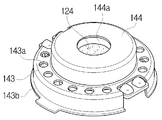
- the tweeter section 120 The first treble coil 121, the first treble magnet 122, the first gap guide 123, the treble diaphragm 124, the second gap guide 125, the second treble magnet 126, And a second treble coil 127.
- the lower frame 140a includes a frame body 142 and a woofer cover 141.
- a cylindrical groove is formed at a central portion of the frame body 142 to support the cylindrical yoke 111
- a shaft column 142a protrudes from the center so that the respective components can be coupled to the same axis.
- the woofer 110 has a magnet 112 and a plate 113 sequentially stacked on the inner side of the yoke 111 to form a gap between the yoke 111 and the plate 113.
- the voice coil 114 Is attached to the bottom surface of the bass part diaphragm 115 and is disposed in the air gap.
- the bass diaphragm 115 comprises a central dome portion and a peripheral edge portion.
- the woofer 110 operates as a dynamic speaker that vibrates the bass diaphragm 115 while interacting with the magnetic field between the magnet 112 and the yoke 111 when a current flows through the voice coil 114.
- the tweeter portion 120 floats in space by gap guides 123 and 125 serving as dampers on both the upper and lower sides of the central treble diaphragm 124.
- a first coil 121 and a second coil 121 are disposed below the treble diaphragm 124,
- the first magnet 122 is arranged in the horizontal direction and the second magnet 126 and the second coil 127 are arranged in the horizontal direction on the upper side of the high-tone diaphragm 124.
- the magnets 122 and 126 and the coils 121 and 127 are all ring-shaped, and the magnets 122 and 126 are disposed outside the coils 121 and 127.
- the magnets 122 and 126, (123, 125) are inserted to form a space for vibration of the treble diaphragm (125).
- the high-tone diaphragm 124 When the current does not flow, the high-tone diaphragm 124 is neutralized and the high-diaphragm 124 is balanced by the vertical magnetic field balancing of the first and second magnets 122 and 126 and the restoring force of the diaphragm itself.
- the high-frequency part diaphragm 124 is N-polarized while the inner magnetic-field directions of the coils 121 and 127 are facing inward toward each other, And when the current flow is negative (-), the direction of the internal magnetic field of each coil is mutually opposed toward the outside, so that the high-frequency part diaphragm 124 becomes S-polarized, so that the high-tone part diaphragm 124 moves downward And operates as a plate-type electromagnet speaker for movement.
- the magnetization direction may be changed according to the arrangement direction of the magnetic poles of the first magnet 122 and the second magnet 126.
- the substrate 130 has a structure in which an electrode pad 132 is formed on a printed circuit board 131 and is disposed between the woofer 110 and the tweeter 120 to separate the bass and treble spaces,
- the audio signal current is supplied to the first coil 121 and the second coil 127 of the tweeter unit 120 and the voice coil 114 of the first tweeter unit 110, respectively.
- the upper frame 140b includes a bass case 143 formed with a bass outlet 143a for discharging a low frequency sound generated in the bass space of the woofer 110, And a treble case 144 having a treble discharge port 144a for discharging sound.
- the bass case 143 is formed in the circumference portion, and the treble case 144 is protruded from the center portion.
- one high sound output port 144a is formed at a central portion of the treble case 144, and a plurality of low sound output ports 143a are formed at the periphery of the low sound output case 143 .
- the low sound output port 143a and the high sound output port 144a are separated from each other, it is possible to perform high-frequency sound tuning by adjusting the area and arrangement of the low sound output ports.
- FIG. 6 is a perspective view of a woofer subassembly of a hybrid speaker according to the present invention
- FIG. 7 is a perspective view of a tweeter subassembly of a hybrid speaker according to the present invention
- FIG. 8 is an acoustic characteristic diagram of a hybrid speaker according to the present invention.
- an audio current flows to the voice coil 114 of the woofer portion.
- a magnetic field is formed in accordance with the direction of current when a current flows in the voice coil 114 disposed in the gap of the magnetic circuit composed of the magnet 112 of the woofer 110 and the yoke 111,
- the bass part diaphragm 115 vibrates vertically while the bass part of the woofer part generated by the vibration of the bass part diaphragm 115 is discharged to the outside through the bass sound outlet 143a of the upper frame.
- a current flows also in the first coil 121 and the second coil 127 of the tweeter section, and the first coil 121 and the second coil 127 Operates as an electromagnet to magnetize the treble diaphragm 124 while interacting with the first magnet 122 and the second magnet 126.
- the diaphragm 124 vibrates vertically according to the magnetization direction of the treble diaphragm 124 to generate treble sound of the tweeter, and the treble of the tweeter is emitted to the outside through the treble outlet 144a.
- the low sound is emitted through the low sound output port 143a and the high sound generated from the tweeter 120 is discharged through the high sound output port 144a, thereby reducing the loss of high sound and improving the sound quality.
- the improved acoustic characteristics of the present invention are significantly improved in acoustic characteristics as compared with the conventional structure having one outlet.
- G2 is a graph of a conventional acoustic characteristic
- G1 is an acoustic characteristic graph according to the present invention. Comparing both graphs, the speaker of the present invention has improved acoustic characteristics .
Landscapes
- Physics & Mathematics (AREA)
- Engineering & Computer Science (AREA)
- Acoustics & Sound (AREA)
- Signal Processing (AREA)
- Health & Medical Sciences (AREA)
- Otolaryngology (AREA)
- Audible-Bandwidth Dynamoelectric Transducers Other Than Pickups (AREA)
- Obtaining Desirable Characteristics In Audible-Bandwidth Transducers (AREA)
- Electrostatic, Electromagnetic, Magneto- Strictive, And Variable-Resistance Transducers (AREA)
Abstract
본 발명은 고역대의 트위터와 저역대의 우퍼가 동일 축으로 구성된 하이브리드 스피커에서 고역대의 트위터에서 발생하는 고역 음과 저역대의 우퍼에서 발생하는 저역 음을 분리하여 방출함으로써 음질을 개선한 하이브리드 스피커에 관한 것이다. 본 발명의 장치는, 저역 음을 방생하는 우퍼부; 고역 음을 발생하는 트위터부; 상기 우퍼부와 트위터부의 코일에 전기적인 신호를 공급하기 위한 기판; 구성부품을 동일 축 상에 수용하기 위한 하부 프레임; 및 상기 하부 프레임과 결합되어 스피커 하우징을 형성하고, 상기 우퍼부의 저역 음을 방출하기 위한 저역 음 방출구와 상기 트위터부에서 발생하는 고역 음을 방출하기 위한 고역 음 방출구가 분리 형성된 상부 프레임을 포함한다. 본 발명에 따른 하이브리드 스피커는 동일 축으로 구성된 고역대의 트위터(Tweeter)와 저역대의 우퍼(Woofer)가 결합된 하이브리드 구조를 가지면서도 고역대의 트위터와 저역대의 우퍼가 각각의 음 방출구를 가지고 있어 성능을 극대화할 수 있고, 고역대 트위터의 프레임(Frame)을 저역대의 우퍼 커버(Cover)로 대체할 수 있어 공정이 단순화되어 생산성을 높일 수 있는 효과가 있다.
Description
본 발명은 스피커에 관한 것으로, 더욱 상세하게는 고역대의 트위터와 저역대의 우퍼가 동일 축으로 구성된 하이브리드 스피커에서 고역대의 트위터에서 발생하는 고역 음과 저역대의 우퍼에서 발생하는 저역 음을 분리하여 방출함으로써 음질을 개선한 하이브리드 스피커에 관한 것이다.
일반적으로, 스피커는 전기신호를 음파로 변환시키는 원리와 방법에 따라 동전형(動電型), 전자기형, 정전형(靜電型), 유전체형(誘電體型), 자기왜형(磁氣歪型) 등으로 구분되는데, 가장 널리 사용되는 동전형(dynamic)은 마그넷의 자기장 내에 있는 코일(보이스 코일)에 음성신호 전류를 흘리면 그 전류의 세기에 따라 기계적인 힘이 코일에 작용하여 운동을 일으키는 원리를 이용한 것이다. 또한 스피커는 진동판이 공기 중에 직접 놓이는 복사형 스피커와 진동판이 혼(horn) 속에 놓이는 혼형 스피커로 구분하기도 한다.
한편, 자성체의 아마추어 진동에 의해 동작하는 마그네틱 스피커를 발란스드 아마추어 스피커(Balanced Armature Speaker)라 하는데, 아마추어 스피커는 금속 케이스 내부의 코일 위 아래에 있는 아마추어(armature)가 코일과 함께 있는 마그넷에 의해 코일 사이에서 균형을 이루며 어느 쪽에도 붙어있지 않고 떠 있는 상태가 된다. 이때 내부 코일에 전류가 흐르게 되면 코일이 자성을 띄게 되어 금속재질의 아마추어가 자성에 따라 진동운동을 하고, 그 진동이 얇은 로드(Rod)를 통해 다이어프램(진동판)으로 전달되어, 최종적으로 진동판이 진동하여 소리를 내게 된다. 통상, 진동판의 재질은 100% 금속판이나 금속에 플라스틱 피막, 플라스틱 판 등 다양한 소재를 사용한다. 이러한 BA 스피커는 보청기용으로 발명된 드라이버이기 때문에 크기가 작고 무게도 가볍다.
전자기형 스피커 중에서 플레이트형 스피커는 별도의 2차 진동 전달요소가 불필요하고, 진동 플레이트가 직접적으로 공기를 진동시켜 음파를 재현할 수 있으므로 공급된 전기 신호의 미세한 신호에도 매우 충실하게 응답하는 고속 반응성을 가진다. 이러한 플레이트형 스피커로는 대한민국 특허 등록번호 제1596894호로 공고된 밸런스드 플레이트 방식의 전자석 스피커가 있다.
공고된 전자석 스피커는 상부코일과, 이 상부 코일의 하부에 배치된 하부 코일과, 상부 코일과 하부 코일 사이에 배치된 진동판과, 상부 코일 및 하부 코일의 외측에 배치된 하나 이상의 마그넷과, 진동판의 상면을 지지하는 상부 댐핑부재와, 진동판의 저면을 지지하는 하부 댐핑부재로 구성된다. 이러한 종래의 전자기형 스피커는 전류흐름이 0일 때는 진동판이 중성화가 되고 상부 및 하부 마그넷의 상하 자기장 밸런싱과 진동판 자체의 복원력에 의해서 진동판이 중앙에 위치하다가 전류 흐름이 양(+)의 주기일 때는 상부코일의 내부 자기장 방향과 하부코일의 내부 자기장 방향이 내측을 향해 상호 대향적으로 이루어지고, 이로 인하여 진동판은 N극화가 되므로 진동판은 상부방향으로 운동하고, 전류흐름이 음(-)의 주기일 때는 상부코일의 내부 자기장방향과 하부코일의 내부 자기장방향이 외측을 향해 상호 대향적으로 이루어지고, 이에 진동판은 S극화가 되므로 진동판은 하부방향으로 운동한다.그런데 이러한 종래의 전자기형 스피커는 평면상의 일체화된 단일 진동판이 상부 및 하부 댐퍼부재에 의해 지지되고, 그 외측에 갭 가이드가 마련되므로 진폭공간이 필요함은 물론 자기저항이 증가하여 효율이 감소하며 스피커 자체의 두께가 확대되는 문제점이 있었다. 특히, 종래의 전자기형 스피커들은 해상도는 좋으나, 대부분 저음과 초고음의 확장에 제한적 성능을 보이고 있어 고음과 저음에서 보다 뛰어난 고품질의 음향 재생을 위한 새로운 특성의 스피커가 요구되고 있다.
본 발명은 상기와 같은 요구를 충족하기 위해서 제안된 것으로, 본 발명의 목적은 고역대의 트위터에서 발생하는 고역 음과 저역대의 우퍼에서 발생하는 저역 음을 분리하여 방출함으로써 음 손실을 줄일 수 있는 하이브리드 스피커를 제공하는 것이다.
본 구현 예는 우퍼부의 저음 공간에서 형성된 저역 음의 방출경로와 트위터부의 고음 공간에서 형성된 고역 음 방출경로가 서로 겹치지 않고 분리된 하이브리드 스피커를 개시한다.
본 구현 예의 하이브리드 스피커는 자기회로상에 배치된 저음부 보이스 코일에 전류가 흐르면 저음부 다이어프램이 진동하면서 저역 음을 발생하는 다이나믹 스피커로 구현된 우퍼부와, 평형 상태의 고음부 다이어프램을 기준으로 상측과 하측에 마그넷과 코일이 각각 배치되어 있고, 상측과 하측 코일에 전류가 흐르면 각 코일이 전자석이 되면서 고음부 다이어프램을 자화시켜 고역 음을 발생하는 플레이트형 전자석 스피커로 구현된 트위터부와, 상기 우퍼부와 상기 트위터부의 사이에 배치되어 우퍼부의 저음 공간과 트위터부의 고음 공간을 구분하면서 우퍼부와 트위터부의 각 코일에 전기적인 신호를 공급하기 위한 기판과, 구성부품을 동일 축 상에 수용하기 위한 하부 프레임과, 상기 하부 프레임과 결합되어 단일체의 스피커 하우징을 형성하고, 상기 우퍼부의 저역 음을 방출하기 위한 저역 음 방출구와 상기 트위터부의 고역 음을 방출하기 위한 고역 음 방출구가 분리되어 있으면서 동일방향으로 음을 방출하도록 하는 상부 프레임을 포함한다.
상기 하부 프레임은 우퍼부의 요크와 마그넷을 수용하기 위한 프레임 몸체와, 저음부 다이어프레임을 수용하면서 상부 프레임을 지지하기 위한 우퍼 커버로 구성된다.
상기 상부 프레임은 우퍼부의 저음 공간에서 생성된 저역 음을 스피커 하우징의 주변부에서 방출하기 위한 저음 방출구가 형성된 저음 케이스와, 트위터부의 고음 공간에서 생성된 고역 음을 스피커 하우징의 중앙에서 방출하기 위한 고음 방출구가 형성된 고음 케이스로 이루어져 저음 방출구의 면적이나 배치를 조절하여 고역 음의 음향 튜닝이 가능한 것이다.
본 발명에 따른 스피커는 고역대의 트위터 (Tweeter)를 고음 특성이 양호한 플레이트형 전자석 스피커로 구현하고, 저역대의 우퍼(Woofer)를 다이나믹형 스피커로 구현하여 전자석 스피커와 다이나믹 스피커가 결합된 하이브리드 구조를 가져 전체 형상이 박형이면서도 저역과 고역의 전 대역에 걸쳐 음향 특성을 향상시킬 수 있는 효과가 있다.
또한 본 발명에 따른 스피커는 고역대의 트위터와 저역대의 우퍼가 동일축 상에 단일체로 구현되면서도 각각의 음 방출구를 별도로 가지고 있어 성능을 극대화할 수 있고, 고역대 트위터의 프레임(Frame)을 저역대의 우퍼 커버(Cover)로 대체할 수 있어 공정이 단순화되어 생산성을 높일 수 있는 효과가 있다.
그리고 본 발명에 따르면, 고역대의 트위터(Tweeter)와 저역대의 우퍼( Woofer)의 사이즈를 다르게 하여 전체 스피커를 슬림화할 수 있고, 저음 방출구와 고음 방출구가 분리되어 있으므로 저음 방출구의 면적이나 배치 등을 조절하여 고역대의 음향을 쉽게 튜닝할 수 있는 잇점이 있다.
도 1은 본 발명에 따른 하이브리드 스피커의 분해 사시도,
도 2는 본 발명에 따른 하이브리드 스피커의 결합 사시도,
도 3은 본 발명에 따른 하이브리드 스피커의 측 단면도,
도 4는 본 발명에 따른 하이브리드 스피커의 평면도,
도 5는 본 발명에 따른 하이브리드 스피커의 정면도,
도 6은 본 발명에 따른 하이브리드 스피커의 우퍼부 서브 앗세이 사시도,
도 7은 본 발명에 따른 하이브리드 스피커의 트위터부 서브 앗세이 사시도,
도 8은 본 발명에 따른 하이브리드 스피커의 음향 특성도이다.
본 발명과 본 발명의 실시에 의해 달성되는 기술적 과제는 다음에서 설명하는 본 발명의 바람직한 실시예들에 의하여 보다 명확해질 것이다. 다음의 실시예들은 단지 본 발명을 설명하기 위하여 예시된 것에 불과하며, 본 발명의 범위를 제한하기 위한 것은 아니다.
도 1은 본 발명에 따른 하이브리드 스피커의 분해 사시도이고, 도 2는 본 발명에 따른 하이브리드 스피커의 결합 사시도이며, 도 3은 본 발명에 따른 하이브리드 스피커의 측 단면도이고, 도 4는 본 발명에 따른 하이브리드 스피커의 평면도이며, 도 5는 본 발명에 따른 하이브리드 스피커의 정면도이다.
본 발명에 따른 하이브리드 스피커(100)는 도 1 내지 도 5에 도시된 바와 같이, 저음 특성이 양호한 우퍼부(110)와, 고음 특성이 양호한 트위터부(120)와, 우퍼부(110)의 저음 공간과 트위터부(120)의 고음 공간을 구분하면서 코일에 전기적인 신호를 공급하기 위한 기판(130)이 하부 프레임(140a)과 상부 프레임(140b) 사이의 동일 축 상에 일체로 결합되어 있다.
우퍼부(110)는 요크(111)와, 저음부 마그넷(112)과, 플레이트(113), 저음부 보이스코일(114), 저음부 다이어프레임(115)으로 이루어진 다이나믹형 스피커이고, 트위터부(120)는 제1 고음부 코일(121)과, 제1 고음부 마그넷(122)과, 제1 갭 가이드(123)와, 고음부 다이어프램(124)과, 제2 갭가이드(125)와, 제2 고음부 마그넷(126)과 제2 고음부 코일(127)로 구성된 플레이트형 전자석 스피커이다.
도 1 내지 도 3을 참조하면, 하부 프레임(140a)은 프레임 몸체(142)와 우퍼 커버(141)로 이루어지는데, 프레임 몸체(142)의 중앙 부분에 원통형 홈이 형성되어 원통형 요크(111)를 수용할 수 있도록 되어 있고, 중앙에는 축기둥(142a)이 돌출되어 각 구성요소들을 동일 축으로 결합할 수 있도록 되어 있다.
우퍼부(110)는 요크(111)의 내측에 마그넷(112)과 플레이트(113)가 순차적으로 적층되어 요크(111)와 플레이트(113) 사이에 공극을 형성하고 있고, 보이스 코일(114)은 저음부 다이어프램(115)의 저면에 부착되어 있으면서 공극에 배치되어 있다. 저음부 다이어프램(115)은 중앙의 돔부와 주변의 에지부로 이루어져 있다.
이와 같은 우퍼부(110)는 보이스 코일(114)에 전류가 흐르면 마그넷(112)과 요크(111) 사이의 자기장과 상호 작용하면서 저음부 다이어프램(115)을 진동시키는 다이나믹형 스피커로서 동작한다.
트위터부(120)는 중앙의 고음부 다이어프램(124)이 상하 양측의 댐퍼 역할을 하는 갭 가이드(123,125)에 의해 공간상에 플로팅되어 있고, 고음부 다이어프램(124)의 하측에는 제1 코일(121)과 제1 마그넷(122)이 수평방향으로 배치되어 있으며, 고음부 다이어프램(124)의 상측에는 제2 마그넷(126)과 제2 코일(127)이 수평방향으로 배치되어 있다. 본 발명의 실시예에서 마그넷(122,126)이나 코일(121,127)은 모두 링형으로서 코일(121,127)의 외측에 마그넷(122,126)이 배치된 구조이고, 각 마그넷(122,126)과 진동판(124) 사이에 갭 가이드(123,125)가 끼워져 고음부 다이어프램(125)의 진동을 위한 공간을 형성하고 있다.
이와 같이 구성되는 트위터부(120)는 전류가 흐르지 않을 때는 고음부 다이어프램(124)이 중성화가 되고, 제1 및 제2 마그넷(122,126)의 상하 자기장 밸런싱과 다이어프램 자체의 복원력에 의해서 고음부 다이어프램(124)이 중앙에 위치하다가 전류 흐름이 양(+)의 주기일 때는 각 코일(121,127)의 내부 자기장 방향이 내측을 향해 상호 대향되면서 고음부 다이어프램(124)은 N극화가 되므로 고음부 다이어프램(124)은 상부방향으로 운동하고, 전류 흐름이 음(-)의 주기일 때는 각 코일의 내부 자기장 방향이 외측을 향해 상호 대향적으로 이루어지면서 고음부 다이어프램(124)은 S극화가 되므로 고음부 다이어프램(124)은 하부방향으로 운동하는 플레이트형 전자석 스피커로서 동작한다. 이때 제1 마그넷(122)과 제2 마그넷(126)의 자극 배열 방향에 따라 자극화 방향이 달라질 수 있다.
기판(130)은 인쇄회로기판(131)에 전극패드(132)가 형성된 구조로서, 우퍼부(110)와 트위터부(120) 사이에 배치되어 저음 공간과 고음 공간을 구분함과 아울러 우퍼부(110)의 보이스 코일(114)과 트위터부(120)의 제1 코일(121) 및 제2 코일(127)에 오디오 신호 전류를 각각 공급한다.
상부 프레임(140b)은 우퍼부(110)의 저음 공간에서 생성된 저역 음을 방출하기 위한 저음 방출구(143a)가 형성된 저음 케이스(143)와, 트위터부(120)의 고음 공간에서 생성된 고역 음을 방출하기 위한 고음 방출구(144a)가 형성된 고음 케이스(144)로 이루어진다. 본 발명의 실시예에서 저음 케이스(143)는 원주부에 형성되어 있고, 고음 케이스(144)는 중앙 부분에서 돌출되어 있다. 그리고 본 발명의 실시예에서 고음 방출구(144a)는 고음 케이스(144)의 중앙 부분에 1개 형성되어 있고, 저음 방출구(143a)는 저음 케이스(143)의 둘레부분에 다수개 형성되어 있다. 이와 같이 본 발명에서는 저음 방출구(143a)와 고음 방출구(144a)가 분리되어 있으므로 저음 방출구의 면적이나 배치 등을 조절하여 고역대의 음향 튜닝이 가능한 잇점이 있다.
또한 본 발명의 실시예에서는 고음 방출구와 저음 방출구의 면적비는 고음 방출구의 면적을 기준으로 저음 방출구의 면적이 50% 내지 100%이고, 고음 방출구의 중심과 저음 방출구 중심 사이의 거리 D는 스피커 폭을 W, 스피커 두께를 T라 할 때 대략 D= 4.5W/T인 것이다.
도 6은 본 발명에 따른 하이브리드 스피커의 우퍼 서브 앗세이 사시도이고, 도 7은 본 발명에 따른 하이브리드 스피커의 트위터 서브 앗세이 사시도이며, 도 8은 본 발명에 따른 하이브리드 스피커의 음향 특성도이다.
본 발명에 따른 하이브리드 스피커의 기판(130)에 외부로부터 오디오신호가 인가되면, 우퍼부의 보이스 코일(114)에 오디오 전류가 흐르게 된다. 우퍼부(110)의 마그넷(112)과 플레이트(123) 및 요크(111)로 이루어진 자기회로의 공극에 배치된 보이스 코일(114)에 전류가 흐르게 되면 전류의 방향에 따라 자기장이 형성되어 자기회로와 상호작용하면서 저음부 다이어프램(115)이 상하로 진동하게 되고, 저음부 다이어프램(115)의 진동에 의해 발생된 우퍼부의 저음은 상부 프레임의 저음 방출구(143a)를 통해 외부로 방출된다.
한편, 하이브리드 스피커의 기판(130)에 외부로부터 오디오신호가 인가되면, 트위터부의 제 1 코일(121)과 제 2 코일(127)에도 전류가 흐르게 되어 제 1 코일(121)과 제2 코일(127)은 전자석으로 작동하면서 제1 마그넷(122) 및 제2 마그넷(126)과 상호작용하면서 고음부 다이어프램(124)을 자화시키게 된다. 그리고 고음부 다이어프램(124)의 자화 방향에 따라 다이어프램(124)은 상하로 진동하면서 트위터부의 고음을 발생시키고, 트위터의 고음은 고음 방출구(144a)를 통해 외부로 방출된다.
이와 같이 본 발명에 따른 하이브리드 스피커(100)는 도 6에 도시된 우퍼 앗세이와 도 7에 도시된 트위터 서브 앗세이가 동일 축 상에 상하로 배치된 구조인데, 우퍼부(110)에서 발생된 저음이 저음 방출구(143a)를 통해 방출되고, 트위터부(120)에서 발생된 고음이 고음 방출구(144a)를 통해 방출되면서 고음의 손실을 줄일 수 있어 음질이 개선되는 효과가 있다.
이와 같이 개선된 본 발명의 음향 특성은 도 8에 도시된 그래프에서와 같이 종래 방출구가 1개인 구조에 비해 음향특성이 크게 개선된 것을 알 수 있다.
도 8을 참조하면, 도시된 그래프에서 G2는 종래의 음향 특성 그래프이고, G1은 본 발명에 따른 음향 특성 그래프인데, 양 그래프를 비교하면, 본 발명의 스피커는 저음과 고음에서 음향 특성이 개선된 것을 확인할 수 있다.
이상에서 본 발명은 도면에 도시된 일 실시예를 참고로 설명되었으나, 본 기술분야의 통상의 지식을 가진 자라면 이로부터 다양한 변형 및 균등한 타 실시예가 가능하다는 점을 이해할 것이다.
Claims (3)
- 자기회로상에 배치된 저음부 보이스 코일에 전류가 흐르면 저음부 다이어프램이 진동하면서 저역 음을 발생하는 다이나믹 스피커로 구현된 우퍼부;평형 상태의 고음부 다이어프램을 기준으로 상측과 하측에 마그넷과 코일이 각각 배치되어 있고, 상측과 하측 코일에 전류가 흐르면 각 코일이 전자석이 되면서 고음부 다이어프램을 자화시켜 고역 음을 발생하는 플레이트형 전자석 스피커로 구현된 트위터부;상기 우퍼부와 상기 트위터부의 사이에 배치되어 우퍼부의 저음 공간과 트위터부의 고음 공간을 구분하면서 우퍼부와 트위터부의 각 코일에 전기적인 신호를 공급하기 위한 기판;구성부품을 동일 축 상에 수용하기 위한 하부 프레임; 및상기 하부 프레임과 결합되어 단일체의 스피커 하우징을 형성하고, 상기 우퍼부의 저역 음을 방출하기 위한 저역 음 방출구와 상기 트위터부의 고역 음을 방출하기 위한 고역 음 방출구가 분리되어 있으면서 동일방향으로 음을 방출하도록 하는 상부 프레임을 포함하여우퍼부의 저음 공간에서 형성된 저역 음의 방출경로와 트위터부의 고음 공간에서 형성된 고역 음 방출경로가 서로 겹치지 않고 분리된 것을 특징으로 하는 하이브리드 스피커.
- 제1항에 있어서, 상기 하부 프레임은우퍼부의 요크와 마그넷을 수용하기 위한 프레임 몸체와, 저음부 다이어프레임을 수용하면서 상부 프레임을 지지하기 위한 우퍼 커버로 구성된 것을 특징으로 하는 하이브리드 스피커.
- 제1항에 있어서, 상기 상부 프레임은우퍼부의 저음 공간에서 생성된 저역 음을 스피커 하우징의 주변부에서 방출하기 위한 저음 방출구가 형성된 저음 케이스와, 트위터부의 고음 공간에서 생성된 고역 음을 스피커 하우징의 중앙에서 방출하기 위한 고음 방출구가 형성된 고음 케이스로 이루어져저음 방출구의 면적이나 배치를 조절하여 고역 음의 음향 튜닝이 가능한 것을 특징으로 하는 하이브리드 스피커.
Priority Applications (4)
| Application Number | Priority Date | Filing Date | Title |
|---|---|---|---|
| US16/652,262 US11128948B2 (en) | 2017-11-20 | 2018-07-16 | Hybrid speaker |
| CN201880061377.4A CN111164989B (zh) | 2017-11-20 | 2018-07-16 | 混合扬声器 |
| EP18879371.5A EP3716643A4 (en) | 2017-11-20 | 2018-07-16 | HYBRID SPEAKERS |
| JP2020538506A JP6926341B2 (ja) | 2017-11-20 | 2018-07-16 | ハイブリッドスピーカー |
Applications Claiming Priority (2)
| Application Number | Priority Date | Filing Date | Title |
|---|---|---|---|
| KR10-2017-0155045 | 2017-11-20 | ||
| KR1020170155045A KR101907513B1 (ko) | 2017-11-20 | 2017-11-20 | 하이브리드 스피커 |
Publications (1)
| Publication Number | Publication Date |
|---|---|
| WO2019098487A1 true WO2019098487A1 (ko) | 2019-05-23 |
Family
ID=63876299
Family Applications (1)
| Application Number | Title | Priority Date | Filing Date |
|---|---|---|---|
| PCT/KR2018/008031 Ceased WO2019098487A1 (ko) | 2017-11-20 | 2018-07-16 | 하이브리드 스피커 |
Country Status (6)
| Country | Link |
|---|---|
| US (1) | US11128948B2 (ko) |
| EP (1) | EP3716643A4 (ko) |
| JP (1) | JP6926341B2 (ko) |
| KR (1) | KR101907513B1 (ko) |
| CN (1) | CN111164989B (ko) |
| WO (1) | WO2019098487A1 (ko) |
Families Citing this family (22)
| Publication number | Priority date | Publication date | Assignee | Title |
|---|---|---|---|---|
| KR102070202B1 (ko) | 2018-11-13 | 2020-01-29 | 주식회사 비에스이 | 실장이 용이한 하이브리드 스피커 |
| KR102277889B1 (ko) * | 2019-11-08 | 2021-07-15 | 주식회사 비에스이 | 초박형 2웨이 스피커 |
| KR102287436B1 (ko) * | 2020-04-17 | 2021-08-09 | 주식회사 이어브릿지 | 초박형 하이브리드 스피커 |
| CN111836159B (zh) * | 2020-09-21 | 2021-01-22 | 歌尔股份有限公司 | 发声模组 |
| US11528563B2 (en) * | 2020-09-22 | 2022-12-13 | Em-Tech Co., Ltd. | Hybrid receiver having fixing bracket for drivers |
| KR102453587B1 (ko) * | 2020-09-22 | 2022-10-14 | 주식회사 이엠텍 | 마이크 일체형 리시버 모듈 및 이를 구비하는 이어폰 |
| KR20220089739A (ko) * | 2020-12-21 | 2022-06-29 | 현대자동차주식회사 | 전기자동차의 가상 효과 구현 장치 |
| CN114915882B (zh) * | 2021-02-10 | 2024-08-23 | Oppo广东移动通信有限公司 | 混合扬声器及音频再现装置 |
| EP4290883A1 (en) * | 2021-02-10 | 2023-12-13 | Guangdong Oppo Mobile Telecommunications Corp., Ltd. | Hybrid speaker and audio reproduction device |
| CN115226008B (zh) * | 2021-04-15 | 2025-07-01 | Oppo广东移动通信有限公司 | 扬声器及音频再现装置 |
| CN113194390A (zh) * | 2021-04-23 | 2021-07-30 | 歌尔股份有限公司 | 发声装置 |
| CN113781992A (zh) * | 2021-09-17 | 2021-12-10 | 厦门圣德斯贵电子科技有限公司 | 一种微型降噪模块 |
| CN113810832A (zh) * | 2021-09-17 | 2021-12-17 | 厦门圣德斯贵电子科技有限公司 | 微型扬声器 |
| KR102706706B1 (ko) * | 2022-04-21 | 2024-09-19 | 주식회사 이엠텍 | 하이브리드 마이크로스피커 |
| KR102636158B1 (ko) * | 2022-10-05 | 2024-02-14 | 부전전자 주식회사 | MEMS 스피커를 내장한 2way 스피커 |
| KR102676512B1 (ko) * | 2022-10-12 | 2024-06-20 | 주식회사 이엠텍 | 투웨이 스피커용 사운드 필터 |
| US12317051B2 (en) * | 2022-11-25 | 2025-05-27 | Aac Technologies (Nanjing) Co., Ltd. | Multifunctional speaker device |
| US12407977B2 (en) * | 2023-02-27 | 2025-09-02 | Aac Microtech (Changzhou) Co., Ltd. | Speaker device and headphone |
| WO2024207437A1 (zh) * | 2023-04-07 | 2024-10-10 | 瑞声光电科技(常州)有限公司 | 微型扬声器 |
| KR102848476B1 (ko) * | 2024-01-24 | 2025-08-21 | 주식회사 알머스 | 이어폰용 스피커 유닛 |
| CN223053094U (zh) * | 2024-07-25 | 2025-07-01 | 东莞市世威电子科技有限公司 | 一种阵列分频扬声器的耳机 |
| CN119383501A (zh) * | 2024-10-17 | 2025-01-28 | 浙江未来精灵人工智能科技有限公司 | 音箱 |
Citations (5)
| Publication number | Priority date | Publication date | Assignee | Title |
|---|---|---|---|---|
| KR100519637B1 (ko) * | 2002-03-30 | 2005-10-06 | 주식회사 삼부커뮤닉스 | 2-웨이 스피커 |
| JP4006636B2 (ja) * | 2002-10-24 | 2007-11-14 | 日本電気株式会社 | 複合型スピーカ |
| KR101501898B1 (ko) * | 2014-01-28 | 2015-03-23 | 주식회사 진영지앤티 | 일체형 2웨이 스피커 및 이를 포함하는 기기 |
| KR101596894B1 (ko) | 2014-12-30 | 2016-02-23 | 유옥정 | 밸런스드 플레이트 방식의 전자석 스피커 |
| KR101760291B1 (ko) * | 2016-08-23 | 2017-07-24 | 레프릭오디오주식회사 | 다이나믹 스피커를 이용한 일체형 2웨이 스피커 |
Family Cites Families (17)
| Publication number | Priority date | Publication date | Assignee | Title |
|---|---|---|---|---|
| US4418248A (en) * | 1981-12-11 | 1983-11-29 | Koss Corporation | Dual element headphone |
| JP2005277866A (ja) * | 2004-03-25 | 2005-10-06 | Pioneer Electronic Corp | 樹脂フレーム、スピーカーユニット及びスピーカー装置 |
| KR100632480B1 (ko) * | 2004-11-18 | 2006-10-16 | 황경환 | 콘덴서 스피커 |
| US7577269B2 (en) * | 2006-08-28 | 2009-08-18 | Technology Properties Limited | Acoustic transducer |
| CN202121770U (zh) * | 2011-06-24 | 2012-01-18 | 徐曙华 | 功放输出驱动与感应电压驱动复合型全频扬声器 |
| US9036839B2 (en) * | 2013-06-05 | 2015-05-19 | Harman International Industries, Inc. | Multi-way coaxial loudspeaker with magnetic cylinder |
| KR101587477B1 (ko) * | 2013-11-15 | 2016-01-21 | 주식회사 진영지앤티 | 초박형 스피커 |
| CN203859863U (zh) * | 2014-05-20 | 2014-10-01 | 惠阳东美音响制品有限公司 | 同轴同音源扬声器结构 |
| KR101738902B1 (ko) * | 2014-10-23 | 2017-05-25 | 주식회사 알머스 | 다이나믹 스피커와 압전 소자를 이용한 고음질 스피커 |
| CN204046806U (zh) * | 2014-08-20 | 2014-12-24 | 中山市天键电声有限公司 | 一种采用双动圈单元的喇叭 |
| CN204518027U (zh) * | 2015-04-24 | 2015-07-29 | 捷音特科技股份有限公司 | 反向声波耳机 |
| TWM508868U (zh) * | 2015-04-24 | 2015-09-11 | Jetvox Acoustic Corp | 反向聲波耳機 |
| CN204929219U (zh) * | 2015-06-25 | 2015-12-30 | 东莞正任电子有限公司 | 一种耳机扬声器用新型振膜及具有该新型振膜的耳机扬声器 |
| CN205847589U (zh) * | 2016-07-20 | 2016-12-28 | 广州世韵电子科技有限公司 | 一种薄型喇叭结构 |
| KR101909234B1 (ko) * | 2016-11-21 | 2018-10-17 | 주식회사 이어브릿지 | 하이브리드 스피커 |
| CN107046666A (zh) * | 2017-03-06 | 2017-08-15 | 深圳市冠旭电子股份有限公司 | 一种发声装置及耳机 |
| CN107147978A (zh) * | 2017-05-25 | 2017-09-08 | 东莞合律美电子科技有限公司 | 一种分频喇叭 |
-
2017
- 2017-11-20 KR KR1020170155045A patent/KR101907513B1/ko not_active Expired - Fee Related
-
2018
- 2018-07-16 WO PCT/KR2018/008031 patent/WO2019098487A1/ko not_active Ceased
- 2018-07-16 US US16/652,262 patent/US11128948B2/en not_active Expired - Fee Related
- 2018-07-16 CN CN201880061377.4A patent/CN111164989B/zh not_active Expired - Fee Related
- 2018-07-16 EP EP18879371.5A patent/EP3716643A4/en not_active Withdrawn
- 2018-07-16 JP JP2020538506A patent/JP6926341B2/ja not_active Expired - Fee Related
Patent Citations (5)
| Publication number | Priority date | Publication date | Assignee | Title |
|---|---|---|---|---|
| KR100519637B1 (ko) * | 2002-03-30 | 2005-10-06 | 주식회사 삼부커뮤닉스 | 2-웨이 스피커 |
| JP4006636B2 (ja) * | 2002-10-24 | 2007-11-14 | 日本電気株式会社 | 複合型スピーカ |
| KR101501898B1 (ko) * | 2014-01-28 | 2015-03-23 | 주식회사 진영지앤티 | 일체형 2웨이 스피커 및 이를 포함하는 기기 |
| KR101596894B1 (ko) | 2014-12-30 | 2016-02-23 | 유옥정 | 밸런스드 플레이트 방식의 전자석 스피커 |
| KR101760291B1 (ko) * | 2016-08-23 | 2017-07-24 | 레프릭오디오주식회사 | 다이나믹 스피커를 이용한 일체형 2웨이 스피커 |
Non-Patent Citations (1)
| Title |
|---|
| See also references of EP3716643A4 * |
Also Published As
| Publication number | Publication date |
|---|---|
| US20200245058A1 (en) | 2020-07-30 |
| JP2020534769A (ja) | 2020-11-26 |
| JP6926341B2 (ja) | 2021-08-25 |
| KR101907513B1 (ko) | 2018-10-12 |
| EP3716643A1 (en) | 2020-09-30 |
| EP3716643A4 (en) | 2021-08-11 |
| US11128948B2 (en) | 2021-09-21 |
| CN111164989A (zh) | 2020-05-15 |
| CN111164989B (zh) | 2021-08-20 |
Similar Documents
| Publication | Publication Date | Title |
|---|---|---|
| KR101907513B1 (ko) | 하이브리드 스피커 | |
| US10469951B2 (en) | Loudspeaker magnet and earphone assembly | |
| EP1453353A1 (en) | Loudspeaker | |
| KR102277889B1 (ko) | 초박형 2웨이 스피커 | |
| WO2022166388A1 (zh) | 发声装置和耳机 | |
| WO2011059142A1 (ko) | 리본형 스피커 | |
| WO2024007509A1 (zh) | 一种双振膜受话器及电子设备 | |
| KR102070202B1 (ko) | 실장이 용이한 하이브리드 스피커 | |
| US20120308070A1 (en) | Slim type speaker and magnetic circuit therefor | |
| JP4173382B2 (ja) | コアキシャル型複合スピーカ | |
| US20230111935A1 (en) | Electroacoustic transducer and loudspeaker, microphone and electronic device comprising said electroacoustic transducer | |
| US6870941B2 (en) | Dipole radiating dynamic speaker | |
| JPH1141685A (ja) | スピーカ装置 | |
| KR102287436B1 (ko) | 초박형 하이브리드 스피커 | |
| JP2000184482A (ja) | スピーカ及びスピーカ装置 | |
| CN117241186A (zh) | 全频带双面扬声装置 | |
| JPH11234778A (ja) | スピーカ装置 | |
| CN115955636A (zh) | 一种平面扬声器及耳机 | |
| KR101775427B1 (ko) | 스피커 유닛 | |
| KR102658276B1 (ko) | 자성체 진동판을 이용한 평판형 트위터 스피커 | |
| KR102543007B1 (ko) | 평판형 트위터 진동판을 적용한 투웨이 리시버 | |
| CN222531824U (zh) | 同轴扬声器 | |
| CN120583358B (zh) | 发声装置和电子设备 | |
| WO2011059143A1 (ko) | 리본형 스피커 | |
| US12207072B2 (en) | Speaker |
Legal Events
| Date | Code | Title | Description |
|---|---|---|---|
| 121 | Ep: the epo has been informed by wipo that ep was designated in this application |
Ref document number: 18879371 Country of ref document: EP Kind code of ref document: A1 |
|
| ENP | Entry into the national phase |
Ref document number: 2020538506 Country of ref document: JP Kind code of ref document: A |
|
| ENP | Entry into the national phase |
Ref document number: 2018879371 Country of ref document: EP Effective date: 20200622 |