WO2019102697A1 - 着色コンタクトレンズ、着色コンタクトレンズの製造方法及び虹彩照合システム - Google Patents
着色コンタクトレンズ、着色コンタクトレンズの製造方法及び虹彩照合システム Download PDFInfo
- Publication number
- WO2019102697A1 WO2019102697A1 PCT/JP2018/034288 JP2018034288W WO2019102697A1 WO 2019102697 A1 WO2019102697 A1 WO 2019102697A1 JP 2018034288 W JP2018034288 W JP 2018034288W WO 2019102697 A1 WO2019102697 A1 WO 2019102697A1
- Authority
- WO
- WIPO (PCT)
- Prior art keywords
- colored
- contact lens
- iris
- infrared
- colored contact
- Prior art date
- Legal status (The legal status is an assumption and is not a legal conclusion. Google has not performed a legal analysis and makes no representation as to the accuracy of the status listed.)
- Ceased
Links
Images




Classifications
-
- G—PHYSICS
- G02—OPTICS
- G02C—SPECTACLES; SUNGLASSES OR GOGGLES INSOFAR AS THEY HAVE THE SAME FEATURES AS SPECTACLES; CONTACT LENSES
- G02C7/00—Optical parts
- G02C7/02—Lenses; Lens systems ; Methods of designing lenses
- G02C7/04—Contact lenses for the eyes
- G02C7/046—Contact lenses having an iris pattern
-
- B—PERFORMING OPERATIONS; TRANSPORTING
- B29—WORKING OF PLASTICS; WORKING OF SUBSTANCES IN A PLASTIC STATE IN GENERAL
- B29D—PRODUCING PARTICULAR ARTICLES FROM PLASTICS OR FROM SUBSTANCES IN A PLASTIC STATE
- B29D11/00—Producing optical elements, e.g. lenses or prisms
- B29D11/00865—Applying coatings; tinting; colouring
- B29D11/00894—Applying coatings; tinting; colouring colouring or tinting
-
- G—PHYSICS
- G02—OPTICS
- G02C—SPECTACLES; SUNGLASSES OR GOGGLES INSOFAR AS THEY HAVE THE SAME FEATURES AS SPECTACLES; CONTACT LENSES
- G02C7/00—Optical parts
- G02C7/02—Lenses; Lens systems ; Methods of designing lenses
- G02C7/04—Contact lenses for the eyes
- G02C7/049—Contact lenses having special fitting or structural features achieved by special materials or material structures
-
- G—PHYSICS
- G02—OPTICS
- G02C—SPECTACLES; SUNGLASSES OR GOGGLES INSOFAR AS THEY HAVE THE SAME FEATURES AS SPECTACLES; CONTACT LENSES
- G02C7/00—Optical parts
- G02C7/10—Filters, e.g. for facilitating adaptation of the eyes to the dark; Sunglasses
- G02C7/104—Filters, e.g. for facilitating adaptation of the eyes to the dark; Sunglasses having spectral characteristics for purposes other than sun-protection
-
- G—PHYSICS
- G06—COMPUTING OR CALCULATING; COUNTING
- G06F—ELECTRIC DIGITAL DATA PROCESSING
- G06F18/00—Pattern recognition
- G06F18/20—Analysing
- G06F18/25—Fusion techniques
- G06F18/251—Fusion techniques of input or preprocessed data
-
- G—PHYSICS
- G06—COMPUTING OR CALCULATING; COUNTING
- G06V—IMAGE OR VIDEO RECOGNITION OR UNDERSTANDING
- G06V10/00—Arrangements for image or video recognition or understanding
- G06V10/70—Arrangements for image or video recognition or understanding using pattern recognition or machine learning
- G06V10/77—Processing image or video features in feature spaces; using data integration or data reduction, e.g. principal component analysis [PCA] or independent component analysis [ICA] or self-organising maps [SOM]; Blind source separation
- G06V10/80—Fusion, i.e. combining data from various sources at the sensor level, preprocessing level, feature extraction level or classification level
- G06V10/803—Fusion, i.e. combining data from various sources at the sensor level, preprocessing level, feature extraction level or classification level of input or preprocessed data
-
- G—PHYSICS
- G06—COMPUTING OR CALCULATING; COUNTING
- G06V—IMAGE OR VIDEO RECOGNITION OR UNDERSTANDING
- G06V40/00—Recognition of biometric, human-related or animal-related patterns in image or video data
- G06V40/10—Human or animal bodies, e.g. vehicle occupants or pedestrians; Body parts, e.g. hands
- G06V40/18—Eye characteristics, e.g. of the iris
- G06V40/19—Sensors therefor
-
- G—PHYSICS
- G06—COMPUTING OR CALCULATING; COUNTING
- G06V—IMAGE OR VIDEO RECOGNITION OR UNDERSTANDING
- G06V40/00—Recognition of biometric, human-related or animal-related patterns in image or video data
- G06V40/10—Human or animal bodies, e.g. vehicle occupants or pedestrians; Body parts, e.g. hands
- G06V40/18—Eye characteristics, e.g. of the iris
- G06V40/193—Preprocessing; Feature extraction
-
- G—PHYSICS
- G06—COMPUTING OR CALCULATING; COUNTING
- G06V—IMAGE OR VIDEO RECOGNITION OR UNDERSTANDING
- G06V40/00—Recognition of biometric, human-related or animal-related patterns in image or video data
- G06V40/10—Human or animal bodies, e.g. vehicle occupants or pedestrians; Body parts, e.g. hands
- G06V40/18—Eye characteristics, e.g. of the iris
- G06V40/197—Matching; Classification
Definitions
- the present invention relates to a colored contact lens, a method of manufacturing the colored contact lens, and an iris matching system.
- Patent Document 1 discloses a colored contact lens having a colored area. When the colored contact lens is worn, the wearer's iris is covered by the colored area. Therefore, the appearance of the iris changes.
- the present invention has been made in view of the above problems, and it is an object of the present invention to provide a colored contact lens, a method of manufacturing a colored contact lens, and an iris matching system capable of reducing the influence on the accuracy of iris matching. Do.
- the present invention has a lens and a colored area formed on the lens, and at the time of wear, at least a part of the colored area is disposed at a position overlapping with the iris of the wearer.
- a colored contact lens characterized in that the colored area has infrared transparency.
- the present invention there is a step of forming a lens and a step of forming a colored area on the lens, and at the time of wearing, a position where at least a part of the colored area overlaps the iris of the wearer.
- the method for producing a colored contact lens according to the present invention is characterized in that the colored region is infrared-transparent.
- an infrared image acquiring unit for photographing an iris of a person to be collated wearing a colored contact lens having a colored region using infrared light of a wavelength transmitting the colored region;
- a visible light image acquisition unit that captures the iris using visible light;
- a determination unit that determines whether the person to be matched wears the colored contact lens;
- a matching unit that matches the iris
- a colored contact lens a method of manufacturing a colored contact lens, and an iris reference system capable of reducing the influence on the accuracy of iris reference.
- FIG. 2 is a schematic view of an image of an eye wearing a colored contact lens taken by a visible light camera.
- FIG. 2 is a schematic view of an image of an eye wearing a colored contact lens taken by an infrared camera. It is a block diagram showing the example of hardware constitutions of the iris collation system concerning a 1st embodiment.
- iris collation system concerning a 1st embodiment. It is a flow chart which shows iris collation processing concerning a 1st embodiment. It is a functional block diagram of the iris collation system concerning a 2nd embodiment. It is a flowchart which shows the iris collation process which concerns on 2nd Embodiment. It is a top view of the contact lens concerning a 3rd embodiment. It is a flowchart which shows the manufacturing method of the contact lens which concerns on 4th Embodiment.
- FIG. 1 is a plan view of a colored contact lens 10 according to the present embodiment
- FIG. 2 is a cross-sectional view of the colored contact lens 10 according to the present embodiment taken along line AA.
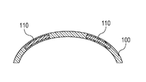
- the colored contact lens 10 has a lens 100 and a colored area 110 formed on the lens 100.
- the lens 100 has a meniscus shape in which one surface is convex and the other is concave.
- the colored area 110 has an annular shape in plan view.
- the colored area 110 is disposed at a position where at least a part thereof overlaps with the iris of the wearer. Thereby, the decorative effect of the iris is obtained.
- the colored area 110 is often disposed at a position covering the outer periphery of the wearer's iris in order to obtain an effect of making the iris appear large.
- the transparent portion 120 is disposed at a position corresponding to the pupil inside the colored area 110. Thereby, when wearing the colored contact lens 10, it is possible to prevent the colored area 110 from blocking the view.
- a coloring contact lens may be called a color contact lens, a circle contact lens, and a cosmetic contact lens.
- region 110 shall be annular
- various shapes may be adopted, such as a pattern in the colored area 110 being radially close to the pattern of an actual iris, or a pattern in which gradation is provided to the color of the colored area 110 by a large number of dot patterns.
- FIG. 3 is a schematic diagram which shows the manufacturing method of the coloring contact lens 10 which concerns on this embodiment. Steps (a) to (d) of FIG. 3 illustrate cross sections of the colored contact lens 10 and a mold 210 for molding the same. Although what is called a sandwich system is shown as an example of the manufacturing method of the coloring contact lens 10 by FIG. 3, a system other than this may be used. Hereinafter, an example of the manufacturing method of the coloring contact lens 10 is demonstrated along the process order of FIG.
- the resin 220 is supplied to the mold 210.
- the resin 220 is molded as a meniscus lens 100 a along the concave surface of the mold 210.
- a spin cast method, a cast molding method, etc. may be used for shaping
- the spin casting method is a method of forming using centrifugal force generated by rotating the mold 210.
- the cast molding method is a method in which molding is performed by fitting a convex mold different from the mold 210 into the recess of the mold 210.
- step (b) a coloring material 230 is formed on the lens 100a.
- the coloring material 230 forms a colored area 110.
- step (c) the resin 220 is supplied again on the lens 100a so as to cover the coloring material 230, and the resin 220 is molded. As a result, the colored area 110 formed by the coloring material 230 is sandwiched in the lens 100. After the resin constituting the lens 100 is solidified, the colored contact lens 10 is released from the mold 210 in step (d).
- the colored contact lens 10 may be either a soft contact lens or a hard contact lens.
- the material of the resin 220 may be a commonly used material such as hydroxyethyl methacrylate, silicone hydrogel, and the like.
- the coloring material 230 a material having infrared transparency is used. As a result, the colored area 110 has infrared transparency. Further, as the coloring material 230, a material having absorbability or reflectivity to visible light is used. As a result, the colored area 110 is opaque to visible light, and it is possible to obtain a decorative effect such as an effect of making the iris look large or an effect of changing the color of the iris.
- a coloring material 230 is commercially available as, for example, an infrared transmitting ink, and may be used as a filter of a transmitting / receiving unit of an infrared communication device.
- visible light refers to light having a wavelength of 400 nm or more and 750 nm or less.
- the light in this range is visually recognizable to many people. Therefore, a material having absorbability or reflectivity for light in the wavelength range can be suitably used as a coloring material.
- Infrared radiation refers to light with a wavelength greater than 750 nm.
- the colored region 110 has infrared transparency, and thus transmits light with a wavelength greater than 750 nm.
- light or the like is simply described without limiting the wavelength, it is not limited to visible light and may include electromagnetic waves of any wavelength such as visible light and infrared light. I assume.
- FIG. 4 is a graph showing an example of the wavelength dependency of the transmittance of the colored region 110 according to the present embodiment.
- the horizontal axis of FIG. 4 indicates the wavelength of light incident on the colored region 110, and the vertical axis indicates the transmittance of light of that wavelength.
- the transmittance of the colored region 110 is a low value for visible light having a wavelength of 400 nm or more and 750 nm or less. Therefore, the colored area 110 is observed as an area colored with a color such as black with a naked eye or a visible light camera.
- the transmittance of the colored region 110 is a high value for infrared rays whose wavelength is greater than 750 nm. Therefore, the colored area 110 is observed as a near transparent area in an infrared camera.
- FIG. 5 is a schematic view of an image of an eye 300 wearing a colored contact lens 10 taken by a visible light camera. As shown in FIG. 5, the end 100 b of the lens 100, the colored area 110, and the transparent portion 120 can be determined from the image captured by the visible light camera. In addition, since the transparent portion 120 is transparent to visible light, the pupil 310 inside the colored contact lens 10 can also be determined from the outside. However, since the colored area 110 obscures the wearer's iris, the pattern of the wearer's iris can not be determined by visible light.
- FIG. 6 is a schematic view of an image of an eye 300 wearing a colored contact lens 10 taken by an infrared camera. As shown in FIG. 6, in the image captured by the infrared camera, the colored region 110 is transparent, so that the pattern 330 of the iris 320 of the wearer inside the colored contact lens 10 can be identified.
- a colored contact lens will cover the iris with colored areas. Therefore, when the iris collation is performed on the wearer of the colored contact lens, the collation accuracy may be deteriorated.
- a pattern near the outer periphery of the iris that is not easily affected by pupil contraction is one of the important elements, but in order to obtain the effect of making the iris appear larger, the colored contact lens has a colored area near the outer periphery of the iris. It is often arranged in In such a case, the influence of deterioration of the matching accuracy is likely to occur.
- the colored contact lens 10 of the present embodiment at least a part of the colored region 110 has infrared transparency. Therefore, even if the iris of the wearer is covered by the colored area 110, it is possible to distinguish the pattern of the wearer's iris by photographing the eye with the infrared camera. Therefore, according to the present embodiment, there is provided a colored contact lens 10 capable of reducing the influence on the accuracy of iris matching.
- the colored contact lens 10 of the present embodiment can perform iris collation even in a worn state. Therefore, there is no need to remove the contact lens at the time of authentication even if iris authentication is employed for identity verification such as identity verification at the time of entering or leaving a facility, for example, when logging in a smartphone, convenience improves Do.
- “having infrared transparency” is not limited to the state in which infrared rays are completely transmitted. By photographing the eye with an infrared camera, it is sufficient if there is such transparency that the iris pattern of the wearer can be determined. For example, when the transmittance of the colored region 110 to infrared light of a wavelength greater than 750 nm and less than 1000 nm is greater than the transmittance of the colored region 110 to visible light of a wavelength of 400 nm or more and 750 nm or less It can be said that. Similarly, “having absorption or reflection” is not limited to the state in which light is not transmitted.
- the colored region 110 may be formed of a coloring material 230 having infrared transparency.
- the coloring material 230 may be formed so as to be sandwiched inside the lens 100.
- the coloring material 230 is not contained on the surface of the lens but is contained inside the lens. Since the coloring material 230 does not touch the eyeballs, eyelids and the like when worn, the colored contact lens 10 of the present embodiment has a structure that is less likely to affect the living body.
- the entire colored region 110 has infrared transparency, and at least a part of the portion of the colored region 110 covering the iris may have infrared transparency.
- the colored contact lens 10 may have a pattern extending to the outside of the wearer's iris, but the portion outside the wearer's iris may not have infrared transparency.
- FIG. 7 is a block diagram showing an example of a hardware configuration of the iris comparison system 40 that performs iris comparison according to the present embodiment.
- the iris verification system 40 may be, for example, a computer such as a mobile phone, a smartphone, a tablet PC (Personal Computer), a laptop PC, a desktop PC, or a data communication terminal.
- the iris matching system 40 has a function of iris matching, which is a type of biometric matching.
- the iris collation system 40 performs iris collation by photographing the iris of the user who is the person to be collated and collating with the registered iris image. The pattern of the iris is unequal and lifelong.
- the iris collation system 40 is installed in a smartphone as an example, and iris collation is assumed to be performed for identity verification at the time of user login, but is not limited thereto. Absent.
- the iris collation system 40 includes a central processing unit (CPU) 401, a random access memory (RAM) 402, a read only memory (ROM) 403, and a flash memory 404 in order to realize a function as a computer that performs calculation and storage. Further, the iris verification system 40 includes a communication I / F (interface) 405, a display device 406, an input device 407, a visible light irradiation device 408, a visible light camera 409, an infrared light irradiation device 410, and an infrared camera 411.
- CPU central processing unit
- RAM random access memory
- ROM read only memory
- flash memory 404 in order to realize a function as a computer that performs calculation and storage.
- the iris verification system 40 includes a communication I / F (interface) 405, a display device 406, an input device 407, a visible light irradiation device 408, a visible light camera 409, an infrared light irradiation device 410
- the display device 406, the input device 407, the visible light irradiation device 408, the visible light camera 409, the infrared light irradiation device 410, and the infrared camera 411 are connected to the bus 412 via a drive device (not shown) for driving these devices. It may be connected.
- each unit constituting the iris collation system 40 is illustrated as an integral device, but a part of these functions may be configured by an external device.
- the visible light irradiation device 408, the visible light camera 409, the infrared light irradiation device 410, or the infrared camera 411 may be an external device different from a portion constituting a function of a computer including the CPU 401 and the like.
- the CPU 401 performs a predetermined operation according to a program stored in the ROM 403, the flash memory 404 or the like, and also has a function of controlling each part of the iris comparison system 40.
- the RAM 402 is composed of a volatile storage medium and provides a temporary memory area necessary for the operation of the CPU 401.
- the ROM 403 is composed of a non-volatile storage medium, and stores necessary information such as a program used for the operation of the iris comparison system 40.
- the flash memory 404 is a storage device configured from a non-volatile storage medium and storing an image captured by the infrared camera 411 or the like, an image to be collated, feature amount data, and the like.
- the communication I / F 405 is a communication interface based on a standard such as Wi-Fi (registered trademark) or 4G, and is a module for communicating with another device.
- the display device 406 is a liquid crystal display, an organic light emitting diode (OLED) display, or the like, and is used to display moving images, still images, characters, and the like.
- the input device 407 is a button, a touch panel or the like, and is used by the user to operate the iris comparison system 40.
- the display device 406 and the input device 407 may be integrally formed as a touch panel.
- the visible light irradiation device 408 and the visible light camera 409 are provided, for example, on the display surface of the display device 406 or the like.
- the visible light irradiation device 408 is used, for example, as a light source for photographing with the visible light camera 409.
- the visible light camera 409 can capture a landscape, a user's face, eyes, and the like by visible light to obtain an image.
- a digital camera using a complementary metal oxide semiconductor (CMOS) image sensor, a charge coupled device (CCD) image sensor, or the like may be used so as to be suitable for image processing after shooting.
- CMOS complementary metal oxide semiconductor
- CCD charge coupled device
- the infrared irradiation device 410 is a light emitting element that emits infrared light, such as an infrared LED.
- the infrared camera 411 a digital camera using a CMOS image sensor provided with a light receiving element configured to have sensitivity to infrared light, a CCD image sensor, or the like may be used.
- the infrared camera 411 can be omitted.
- the wavelength of infrared light emitted from the infrared irradiation device 410 may be, for example, in the range of more than 750 nm and less than 1000 nm.
- the hardware configuration shown in FIG. 7 is an example, and devices other than these may be added, or some devices may not be provided. Also, some devices may be replaced with other devices having similar functions. Furthermore, some functions may be provided by another device via a network, and the functions constituting the present embodiment may be distributed and realized in a plurality of devices.
- the flash memory 404 may be replaced by a hard disk drive (HDD) or a cloud storage.
- FIG. 8 is a functional block diagram of the iris matching system 40 according to the present embodiment.
- the iris collation system 40 includes an infrared irradiation unit 421, an infrared image acquisition unit 422, a feature amount calculation unit 423, a collation unit 424, and a storage unit 425.
- the CPU 401 controls the infrared irradiation device 410 to realize the function of the infrared irradiation unit 421 that irradiates the eye of the person to be verified with infrared light.
- the CPU 401 controls the infrared camera 411 to realize the function of the infrared image acquisition unit 422 that acquires an infrared image of the eye of the person to be verified.
- the CPU 401 loads the program stored in the ROM 403 or the like to the RAM 402 and executes the program to realize the functions of the feature amount calculating unit 423 and the matching unit 424. The processing performed by each of these units will be described later.
- the storage unit 425 stores data such as an iris image acquired by the infrared image acquisition unit 422, an iris image registered in advance, and a feature amount calculated from these iris images.
- the CPU 401 implements the function of the storage unit 425 by controlling the flash memory 404.
- FIG. 9 is a flowchart showing an outline of the iris collation processing performed by the iris collation system 40 according to the present embodiment.
- the infrared irradiation unit 421 irradiates infrared light to a region including the eye of the person to be verified.
- the infrared image acquisition unit 422 acquires an infrared image based on the reflected light of the emitted infrared light.
- the acquired infrared image is stored in the storage unit 425.
- this infrared image is a gray scale image.
- step S102 the feature amount calculation unit 423 calculates a feature amount using the pattern of the iris included in the infrared image.
- the calculated feature amount is stored in the storage unit 425.
- step S103 the matching unit 424 matches the feature amount acquired in step S102 with the feature amount of the iris of the person to be matched, which is registered in advance in the storage unit 425. If it is determined by collation that the iris is the same person, the iris collation system 40 determines that the person verification has been completed, and performs processing such as login.
- iris collation system 40 As described above, according to the iris collation system 40 according to the present embodiment, it is possible to acquire an infrared image of an iris and perform iris collation. Therefore, iris collation can be performed on a subject wearing the colored contact lens 10 having infrared transparency.
- the wavelength of light for acquiring an image of the iris will be described.
- the wavelength used for acquiring the image of the iris may be appropriately selected as long as it is in the range of the infrared region, but it is desirable to set as follows in consideration of the accuracy of iris matching.
- the score indicating the matching degree of matching tends to be high at a wavelength around 800 nm, and high-precision matching is possible. If the wavelength is too long, the score decreases and the accuracy of iris matching decreases, so it is desirable that the wavelength of light for acquiring an image be smaller than 1000 nm.
- the effect of enabling iris authentication even with wearing the colored contact lens 10 is obtained by using an infrared image, so that the wavelength of light for acquiring an iris image is greater than 750 nm. Is desirable. In consideration of these conditions, it is desirable that the wavelength of light for acquiring an iris image be in a range larger than 750 nm and smaller than 1000 nm.
- the colored region 110 of the colored contact lens 10 be also transparent to light larger than 750 nm and smaller than 1000 nm.
- an iris verification system 50 having a function of determining whether or not the colored contact lens 10 is worn will be described.
- FIG. 10 is a functional block diagram of the iris matching system 50 according to the present embodiment.
- the iris collation system 50 further includes a visible light irradiation unit 426, a visible light image acquisition unit 427, and a determination unit 428 in addition to the configuration of the iris collation system 40 according to the first embodiment.
- the CPU 401 controls the visible light irradiation device 408 to realize the function of the visible light irradiation unit 426 for irradiating the eye of the person to be collated with the visible light.
- the CPU 401 controls the visible light camera 409 to realize the function of the visible light image acquisition unit 427 that acquires a visible light image of the eye of the person to be verified.
- the CPU 401 implements the function of the determination unit 428 by loading a program stored in the ROM 403 or the like into the RAM 402 and executing the program. The function of the determination unit 428 will be described later.
- FIG. 11 is a flowchart showing an outline of the iris collation processing performed by the iris collation system 50 according to the present embodiment.
- step S201 acquisition of a visible light image and an infrared image is performed. These images are used to determine the presence or absence of the colored contact lens 10 in the subsequent step S202.
- the infrared image of the eye of the person to be verified is acquired by the same process as step S101 in FIG.
- the visible light irradiation unit 426 and the visible light image acquisition unit 427 acquire a visible light image of the eye of the person to be verified.
- the visible light irradiation unit 426 emits visible light to a region including the eye of the person to be verified.
- the visible light image acquisition unit 427 acquires a visible light image based on the reflected light of the emitted visible light.
- the acquired visible light image is stored in the storage unit 425.
- step S202 the determination unit 428 determines whether the person to be matched wears the colored contact lens 10 using the visible light image and the infrared image acquired in step S201. This determination may be made, for example, based on whether the difference between the portion corresponding to the iris exceeds the threshold value by comparing the visible light image and the infrared image. As understood from FIGS. 5 and 6, the pattern of the part corresponding to the colored region 110 is different between the visible light image and the infrared image. Alternatively, a discriminator that has been learned in advance by machine learning may be used as the determination unit 428. As teaching data for learning, a visible light image and an infrared image when the colored contact lens 10 is worn, and a visible light image and an infrared image when not worn can be used.
- step S202 If it is determined in step S202 that the person to be verified wears the colored contact lens 10 (YES in step S202), the process proceeds to step S203. If it is determined in step S202 that the person to be matched does not wear the colored contact lens 10 (NO in step S202), the process proceeds to step S204.
- step S203 the feature amount calculation unit 423 calculates a feature amount using the pattern of the iris included in the infrared image.
- the calculated feature amount is stored in the storage unit 425.
- step S204 the feature amount calculation unit 423 calculates a feature amount using the pattern of the iris included in the visible light image.
- the calculated feature amount is stored in the storage unit 425.
- the subsequent processing is the same as that of the iris matching system 40 according to the first embodiment, and thus the description thereof is omitted.
- the feature amount may be calculated using an infrared image also in step S204. That is, in the process of step S204, the feature amount may be calculated using either an infrared image or a visible light image. For example, the image used to calculate the feature amount may be changed according to the situation, such as selecting an image in which the pattern of the iris is clearly displayed and using it in the feature amount calculation process.
- the iris collation system 50 of this embodiment can determine whether it wears
- the iris collation system 50 can perform iris collation using an infrared image, and can reduce the influence of the colored contact lens 10 on the collation accuracy.
- the iris collation system 50 can use, for example, a visible light image for iris collation. In this case, it is not necessary to limit which image is used for iris matching. Therefore, the degree of freedom of processing is improved.
- the colored contact lens described in the above embodiment can also be configured as in the following third embodiment.
- FIG. 12 is a plan view of a colored contact lens 60 according to the present embodiment.
- the colored contact lens 60 has a lens 600 and a colored area 610 formed on the lens 600.
- at the time of wearing at least a part of the colored area 610 is disposed at a position overlapping the iris of the wearer.
- the colored region 610 has infrared transparency.
- the method for producing a colored contact lens described in the above embodiment can be configured as in the following fourth embodiment.
- FIG. 13 is a flowchart showing a method of manufacturing a colored contact lens according to the fourth embodiment.
- step S301 formation of a lens is performed.
- step S302 a colored area is formed on the lens.
- the colored region has infrared transparency.
- the iris collation system 40, 50 of the above-mentioned embodiment can be used not only for authentication at the time of login mentioned as an example but for various person verification.
- the iris verification system according to the above-described embodiment includes identity verification for entering and leaving the country at an airport, a seaport and a border, identity verification for an administrative organization, identity verification for entering and leaving a factory or business, and event venues. It can be applied to identity verification at admission.
- acquisition of an image used for iris matching may be performed on one eye of a person to be authenticated or on both eyes.
- acquisition of an image used for iris matching may be performed on one eye of a person to be authenticated or on both eyes.
- a program for operating the configuration of the embodiment to realize the function of the above embodiment is recorded on a storage medium, a program recorded on the storage medium is read as a code, and a processing method executed on a computer is also described in each embodiment. It is included in the category. That is, a computer readable storage medium is also included in the scope of each embodiment. Moreover, not only the storage medium in which the above-mentioned program is recorded, but the program itself is included in each embodiment.
- one or more components included in the above-described embodiment are circuits such as an application specific integrated circuit (ASIC) and a field programmable gate array (FPGA) configured to realize the function of each component. It may be.
- ASIC application specific integrated circuit
- FPGA field programmable gate array
- the storage medium for example, a floppy (registered trademark) disk, a hard disk, an optical disk, a magneto-optical disk, a CD (Compact Disk) -ROM, a magnetic tape, a non-volatile memory card, and a ROM can be used.
- the program is not limited to one in which processing is executed by a single program recorded in the storage medium, but is executed on OS (Operating System) in cooperation with other software and expansion board functions. Are also included in the category of each embodiment.
- SaaS software as a service
- the transmittance of the colored region to light of a wavelength greater than 750 nm and smaller than 1000 nm is greater than the transmittance of the colored region to light of a wavelength of 400 nm or more and 750 nm or less.
- the coloring contact lens as described in a term.
- Appendix 7 The colored contact lens according to any one of appendices 1 to 6, wherein the colored region is disposed at a position covering the outer periphery of the iris when worn.
- the colored area is formed of a coloring material having infrared transparency.
- the colored contact lens according to any one of Appendices 1 to 8, wherein the coloring material is not contained in the surface of the lens but contained in the inside of the lens.
- An infrared image acquisition unit for photographing an iris of a person to be matched wearing a colored contact lens having a colored region using infrared light of a wavelength that transmits the colored region;
- a visible light image acquisition unit that captures the iris using visible light;
- a determination unit that determines whether the person to be matched wears the colored contact lens;
- a collating unit that collates the iris. If the determining unit determines that the person to be matched wears the colored contact lens, the matching unit performs the matching using the image acquired by infrared light, When the determination unit determines that the person to be matched does not wear the colored contact lens, the matching unit performs matching using an image acquired by visible light or infrared light. Iris matching system.
- the colored area is formed of a coloring material having infrared transparency.
Landscapes
- Engineering & Computer Science (AREA)
- Physics & Mathematics (AREA)
- Health & Medical Sciences (AREA)
- Ophthalmology & Optometry (AREA)
- General Physics & Mathematics (AREA)
- General Health & Medical Sciences (AREA)
- Theoretical Computer Science (AREA)
- Multimedia (AREA)
- Computer Vision & Pattern Recognition (AREA)
- Human Computer Interaction (AREA)
- Optics & Photonics (AREA)
- Evolutionary Computation (AREA)
- Artificial Intelligence (AREA)
- Databases & Information Systems (AREA)
- Computing Systems (AREA)
- Medical Informatics (AREA)
- Software Systems (AREA)
- Data Mining & Analysis (AREA)
- Mechanical Engineering (AREA)
- Manufacturing & Machinery (AREA)
- Evolutionary Biology (AREA)
- Bioinformatics & Computational Biology (AREA)
- Bioinformatics & Cheminformatics (AREA)
- General Engineering & Computer Science (AREA)
- Life Sciences & Earth Sciences (AREA)
- Spectroscopy & Molecular Physics (AREA)
- Measurement Of The Respiration, Hearing Ability, Form, And Blood Characteristics Of Living Organisms (AREA)
- Eyeglasses (AREA)
- Image Input (AREA)
- Optical Filters (AREA)
Abstract
レンズと、前記レンズに形成された着色領域とを有し、装用時において、前記着色領域の少なくとも一部が装用者の虹彩と重なる位置に配されており、前記着色領域が赤外線透過性を有することを特徴とする着色コンタクトレンズが提供される。
Description
本発明は、着色コンタクトレンズ及び着色コンタクトレンズの製造方法及び虹彩照合システムに関する。
特許文献1には、着色領域を有する着色コンタクトレンズが開示されている。当該着色コンタクトレンズを装用すると、装用者の虹彩は着色領域に覆われる。そのため、虹彩の外観が変化する。
特許文献1に記載されているような着色コンタクトレンズを装用すると、虹彩の模様の外観が本人の虹彩の模様とは異なるものに変化する。そのため、着色コンタクトレンズの装用者に対して虹彩照合を行うと、照合精度が劣化する場合がある。
本発明は、上述の課題に鑑みてなされたものであって、虹彩照合の精度に対する影響を低減することができる着色コンタクトレンズ及び着色コンタクトレンズの製造方法及び虹彩照合システムを提供することを目的とする。
本発明の一観点によれば、レンズと、前記レンズに形成された着色領域とを有し、装用時において、前記着色領域の少なくとも一部が装用者の虹彩と重なる位置に配されており、前記着色領域が赤外線透過性を有することを特徴とする着色コンタクトレンズが提供される。
本発明の他の観点によれば、レンズを形成するステップと、前記レンズに着色領域を形成するステップとを有し、装用時において、前記着色領域の少なくとも一部が装用者の虹彩と重なる位置に配されており、前記着色領域が赤外線透過性を有することを特徴とする着色コンタクトレンズの製造方法が提供される。
本発明の更に他の観点によれば、着色領域を有する着色コンタクトレンズを装用している照合対象者の虹彩を、前記着色領域を透過する波長の赤外線を用いて撮影する赤外線画像取得部と、前記虹彩を、可視光線を用いて撮影する可視光線画像取得部と、前記照合対象者が前記着色コンタクトレンズを装用しているか否かを判定する判定部と、前記虹彩の照合を行う照合部とを更に有し、前記判定部が、前記照合対象者が前記着色コンタクトレンズを装用していると判定した場合には、前記照合部は、赤外線により取得された画像を用いて照合を行い、前記判定部が、前記照合対象者が前記着色コンタクトレンズを装用していないと判定した場合には、前記照合部は、可視光線又は赤外線により取得された画像を用いて照合を行うことを特徴とする虹彩照合システムが提供される。
本発明によれば、虹彩照合の精度に対する影響を低減することができる着色コンタクトレンズ及び着色コンタクトレンズの製造方法及び虹彩照合システムを提供することができる。
以下、図面を参照して、本発明の例示的な実施形態を説明する。図面において同様の要素又は対応する要素には同一の符号を付し、その説明を省略又は簡略化することがある。
[第1実施形態]
図1は、本実施形態に係る着色コンタクトレンズ10の平面図であり、図2は、本実施形態に係る着色コンタクトレンズ10のA-A線における断面図である。着色コンタクトレンズ10は、レンズ100とレンズ100に形成された着色領域110とを有する。図1及び図2に示されるように、レンズ100が、一方の面が凸面で他方の面が凹面であるメニスカス状をなしている。着色領域110は、平面視において円環状をなしている。着色領域110は、装用時において、少なくとも一部が装用者の虹彩と重なる位置に配されている。これにより、虹彩の装飾効果が得られる。着色領域110は、虹彩を大きく見せる効果を得るため、装用者の虹彩の外周を覆う位置に配されていることが多い。
図1は、本実施形態に係る着色コンタクトレンズ10の平面図であり、図2は、本実施形態に係る着色コンタクトレンズ10のA-A線における断面図である。着色コンタクトレンズ10は、レンズ100とレンズ100に形成された着色領域110とを有する。図1及び図2に示されるように、レンズ100が、一方の面が凸面で他方の面が凹面であるメニスカス状をなしている。着色領域110は、平面視において円環状をなしている。着色領域110は、装用時において、少なくとも一部が装用者の虹彩と重なる位置に配されている。これにより、虹彩の装飾効果が得られる。着色領域110は、虹彩を大きく見せる効果を得るため、装用者の虹彩の外周を覆う位置に配されていることが多い。
また、着色領域110の内側の瞳孔に対応する位置には透明部120が配されている。これにより、着色コンタクトレンズ10の装用時に着色領域110が視界を遮らないようにすることができる。なお、着色コンタクトレンズは、カラーコンタクトレンズ、サークルコンタクトレンズ、コスメティックコンタクトレンズと呼ばれることもある。
なお、図1においては、説明の単純化のために着色領域110の形状が円環状であるものとしているが、これに限られるものではない。例えば、着色領域110の模様が実際の虹彩の模様に近い放射状となっているもの、多数のドットパターンにより着色領域110の色にグラデーションを設けたもの等、種々の形状が採用され得る。
図3は、本実施形態に係る着色コンタクトレンズ10の製造方法を示す模式図である。図3の工程(a)から工程(d)には、着色コンタクトレンズ10及びこれを成形するためのモールド210の断面が図示されている。図3には、着色コンタクトレンズ10の製造方法の一例として、サンドイッチ方式と呼ばれるものが示されているが、これ以外の方式であってもよい。以下、図3の工程順に沿って着色コンタクトレンズ10の製造方法の一例を説明する。
工程(a)において、モールド210に樹脂220が供給される。樹脂220は、モールド210の凹面に沿うようなメニスカス状のレンズ100aとして成形される。この樹脂220の成形には、スピンキャスト法、キャストモールド法等が用いられ得る。スピンキャスト法とは、モールド210を回転させることにより生じた遠心力を利用して成形を行う手法である。キャストモールド法とは、モールド210とは別の凸型のモールドをモールド210の凹部と嵌合させることにより成形を行う手法である。
工程(b)において、レンズ100aの上に着色材料230が形成される。着色材料230は、着色領域110を形成する。その後、工程(c)において、レンズ100aの上に、着色材料230を覆うように再び樹脂220が供給され、樹脂220の成形が行われる。これにより、着色材料230により形成される着色領域110は、レンズ100内に挟み込まれた状態となる。レンズ100を構成する樹脂が固化された後、工程(d)において、着色コンタクトレンズ10は、モールド210から離型される。
着色コンタクトレンズ10は、ソフトコンタクトレンズ、ハードコンタクトレンズのいずれであってもよい。例えば、着色コンタクトレンズ10が、ソフトコンタクトレンズである場合には、樹脂220の材料は、ヒドロキシエチルメタクリレート、シリコーンハイドロゲル等の一般的に用いられているものであり得る。
着色領域110の性質について説明する。着色材料230には、赤外線透過性を有する材料が用いられる。これにより着色領域110は赤外線透過性を有する。また、着色材料230には、可視光線に対して吸収性又は反射性を有する材料が用いられる。これにより、着色領域110は可視光線に対して不透明であり、虹彩を大きく見せる効果、虹彩の色を変える効果等の装飾効果を得ることができる。このような着色材料230は、例えば、赤外線透過インクとして市販されており、赤外線通信装置の送受信部のフィルタ等に用いられることがある。
ここで、可視光線とは、波長が400nm以上、750nm以下の光を指すものとする。この範囲の光は多くの人にとって視覚による認識が可能である。そのため、この範囲の波長の光に対して吸収性又は反射性を有する材料は、着色材料として好適に用いられ得る。赤外線とは、波長が750nmより大きい光を指すものとする。着色領域110は赤外線透過性を有するため、波長が750nmより大きい光を透過する。なお、本明細書において、波長を限定せずに単に「光」等と記載した場合には、それは可視光線に限定されるものではなく、可視光線及び赤外線等のあらゆる波長の電磁波を含み得るものとする。
図4は、本実施形態に係る着色領域110の透過率の波長依存性の例を示すグラフである。図4の横軸は、着色領域110に入射する光の波長を示しており、縦軸は、その波長の光の透過率を示している。図4から理解されるように、着色領域110の透過率は、波長が400nm以上、かつ750nm以下の可視光線に対しては低い値である。そのため、着色領域110は、肉眼又は可視光線カメラでは黒色等の色で着色された領域として観察される。また、着色領域110の透過率は、波長が750nmより大きい赤外線に対しては高い値である。そのため、着色領域110は、赤外線カメラでは透明に近い領域として観察される。
このように、本実施形態の着色コンタクトレンズ10は、着色領域110が上述のような透過率の周波数依存性を有していることにより、着色領域110が可視光線と赤外線のそれぞれに対して異なった外観となる。図5は、可視光線カメラにより撮影された、着色コンタクトレンズ10を装用している眼300の画像の模式図である。図5に示されているように、可視光線カメラにより撮影された画像からは、レンズ100の端部100b、着色領域110及び透明部120が判別可能である。また、透明部120は可視光線に対して透明であるため、着色コンタクトレンズ10の内側の瞳孔310も外部から判別できる。しかしながら、着色領域110により、装用者の虹彩は覆い隠されているため、可視光線によっては、装用者の虹彩の模様が判別できない。
図6は、赤外線カメラにより撮影された、着色コンタクトレンズ10を装用している眼300の画像の模式図である。図6に示されているように、赤外線カメラにより撮影された画像では、着色領域110が透明であるため、着色コンタクトレンズ10の内側にある装用者の虹彩320の模様330が判別可能である。
着色コンタクトレンズを装用すると虹彩が着色領域で覆われる。そのため、着色コンタクトレンズの装用者に対して虹彩照合を行うと、照合精度が劣化する場合がある。虹彩認証においては、瞳孔の収縮に影響されにくい虹彩の外周近傍の模様が重要な要素の1つであるが、着色コンタクトレンズは虹彩を大きく見せる効果を得るため、着色領域が虹彩の外周の近傍に配されていることが多い。このような場合、照合精度の劣化の影響が生じやすい。
これに対し、本実施形態の着色コンタクトレンズ10は、着色領域110の少なくとも一部が赤外線透過性を有する。そのため、着色領域110により装用者の虹彩が覆われたとしても、赤外線カメラで眼を撮影することにより、装用者の虹彩の模様が判別可能である。したがって、本実施形態によれば、虹彩照合の精度に対する影響を低減することができる着色コンタクトレンズ10が提供される。
このように、本実施形態の着色コンタクトレンズ10は、装用した状態であっても虹彩照合を行うことができる。そのため、例えば、スマートフォンのログイン時、施設への入退場時の本人確認等の本人確認に虹彩認証が採用されている場合であっても、認証時にコンタクトレンズを外す必要がなく、利便性が向上する。
なお、「赤外線透過性を有する」とは、赤外線を完全に透過する状態に限定されるものではない。赤外線カメラで眼を撮影することにより、装用者の虹彩の模様が判別可能である程度の透過性があればよい。例えば、750nmより大きく、1000nmより小さい波長の赤外線に対する着色領域110の透過率が、400nm以上、750nm以下の波長の可視光線に対する着色領域110の透過率よりも大きい場合には、赤外線透過性を有するといえる。同様に、「吸収性又は反射性を有する」とは光が透過しない状態に限定されるものではない。
本実施形態では、着色領域110が、赤外線透過性を有する着色材料230により形成され得る。このとき、着色材料230は、レンズ100の内部に挟み込まれた状態となるように形成され得る。この製造方法では、着色材料230は、レンズの表面には含有されておらず、レンズの内部に含有されている。装用時に着色材料230が眼球、まぶた等に触れないため、本実施形態の着色コンタクトレンズ10は、生体への影響を与えにくい構造となっている。
なお、着色領域110の全体が赤外線透過性を有することは必須ではなく、着色領域110のうちの虹彩を覆う部分の少なくとも一部が赤外線透過性を有していればよい。例えば、着色コンタクトレンズ10には、装用者の虹彩の外部にまで及ぶ模様が付されている場合があるが、装用者の虹彩の外部の部分は赤外線透過性を有していなくてもよい。
次に、本実施形態に係る着色コンタクトレンズ10を装用している対象者に対して虹彩照合を行う虹彩照合システムの構成例を説明する。
図7は、本実施形態に係る虹彩の照合を行う虹彩照合システム40のハードウェア構成例を示すブロック図である。虹彩照合システム40は、例えば、携帯電話、スマートフォン、タブレットPC(Personal Computer)、ラップトップPC、デスクトップPC等のコンピュータ又は情報通信端末であり得る。虹彩照合システム40は生体照合の一種である虹彩照合の機能を備える。虹彩照合システム40は、照合対象者であるユーザの虹彩を撮影し、登録されている虹彩画像と照合することにより虹彩照合を行う。虹彩の模様は万人不同かつ終生不変である。そのため、照合時に取得された虹彩の模様をあらかじめ登録されている虹彩の画像と照合することにより同一人物であるか否かを確認することが可能である。以下の説明では、虹彩照合システム40は、一例としてスマートフォンに搭載されているものとし、虹彩照合は、ユーザのログイン時の本人確認のために行われるものを想定するが、これに限られるものではない。
虹彩照合システム40は、演算及び記憶を行うコンピュータとしての機能を実現するため、CPU(Central Processing Unit)401、RAM(Random Access Memory)402、ROM(Read Only Memory)403及びフラッシュメモリ404を備える。また、虹彩照合システム40は、通信I/F(インターフェース)405、表示装置406、入力装置407、可視光線照射装置408、可視光線カメラ409、赤外線照射装置410及び赤外線カメラ411を備える。CPU401、RAM402、ROM403、フラッシュメモリ404、通信I/F405、表示装置406、入力装置407、可視光線照射装置408、可視光線カメラ409、赤外線照射装置410及び赤外線カメラ411は、バス412を介して相互に接続される。なお、表示装置406、入力装置407、可視光線照射装置408、可視光線カメラ409、赤外線照射装置410及び赤外線カメラ411は、これらの装置を駆動するための不図示の駆動装置を介してバス412に接続されてもよい。
図7では、虹彩照合システム40を構成する各部が一体の装置として図示されているが、これらの機能の一部は外付け装置により構成されていてもよい。例えば、可視光線照射装置408、可視光線カメラ409、赤外線照射装置410又は赤外線カメラ411は、CPU401等を含むコンピュータの機能を構成する部分とは別の外付け装置であってもよい。
CPU401は、ROM403、フラッシュメモリ404等に記憶されたプログラムに従って所定の動作を行うとともに、虹彩照合システム40の各部を制御する機能をも有する。RAM402は、揮発性記憶媒体から構成され、CPU401の動作に必要な一時的なメモリ領域を提供する。ROM403は、不揮発性記憶媒体から構成され、虹彩照合システム40の動作に用いられるプログラム等の必要な情報を記憶する。フラッシュメモリ404は、不揮発性記憶媒体から構成され、赤外線カメラ411等で撮影された画像、照合対象となる画像、特徴量データ等の記憶を行う記憶装置である。
通信I/F405は、Wi-Fi(登録商標)、4G等の規格に基づく通信インターフェースであり、他の装置との通信を行うためのモジュールである。表示装置406は、液晶ディスプレイ、OLED(Organic Light Emitting Diode)ディスプレイ等であって、動画、静止画、文字等の表示に用いられる。入力装置407は、ボタン、タッチパネル等であって、ユーザが虹彩照合システム40を操作するために用いられる。表示装置406及び入力装置407は、タッチパネルとして一体に形成されていてもよい。
可視光線照射装置408及び可視光線カメラ409は、例えば、表示装置406の表示面等に設けられる。可視光線照射装置408は、例えば、可視光線カメラ409による撮影のための光源として用いられる。可視光線カメラ409は、風景、ユーザの顔、眼等を可視光線により撮影し、画像を取得することができる。可視光線カメラ409には、撮影後の画像処理に適するように、CMOS(Complementary Metal Oxide Semiconductor)イメージセンサ、CCD(Charge Coupled Device)イメージセンサ等を用いたデジタルカメラが用いられ得る。
赤外線照射装置410は、赤外線LED等の赤外光を発する発光素子である。赤外線カメラ411には、赤外線に対して感度を有するように構成された受光素子を備えたCMOSイメージセンサ、CCDイメージセンサ等を用いたデジタルカメラが用いられ得る。赤外線照射装置410から赤外線をユーザの眼に照射し、虹彩で反射した赤外線を赤外線カメラ411で撮影することにより、虹彩照合に用いられる虹彩画像を撮影することができる。虹彩画像の取得に赤外線を用いることにより、虹彩の色によらず高コントラストな画像が得られ、かつ角膜による反射の影響を低減することができる。なお、可視光線カメラ409が可視光に加えて赤外線による画像を取得可能である場合には赤外線カメラ411を省略することができる。赤外線照射装置410から照射される赤外線の波長は、例えば、750nmより大きく、1000nmより小さい範囲であり得る。
なお、図7に示されているハードウェア構成は例示であり、これら以外の装置が追加されていてもよく、一部の装置が設けられていなくてもよい。また、一部の装置が同様の機能を有する別の装置に置換されていてもよい。更に、一部の機能がネットワークを介して他の装置により提供されてもよく、本実施形態を構成する機能が複数の装置に分散されて実現されるものであってもよい。例えば、フラッシュメモリ404は、HDD(Hard Disk Drive)に置換されていてもよく、クラウドストレージに置換されていてもよい。
図8は、本実施形態に係る虹彩照合システム40の機能ブロック図である。虹彩照合システム40は、赤外線照射部421、赤外線画像取得部422、特徴量算出部423、照合部424及び記憶部425を有する。
CPU401は、赤外線照射装置410を制御することにより、照合対象者の眼に赤外線を照射する赤外線照射部421の機能を実現する。CPU401は、赤外線カメラ411を制御することにより、照合対象者の眼の赤外線画像を取得する赤外線画像取得部422の機能を実現する。CPU401は、ROM403等に記憶されたプログラムをRAM402にロードして実行することにより、特徴量算出部423及び照合部424の機能を実現する。これらの各部で行われる処理については後述する。記憶部425は、赤外線画像取得部422により取得された虹彩画像、あらかじめ登録されている虹彩画像、これらの虹彩画像から算出された特徴量等のデータを記憶する。CPU401は、フラッシュメモリ404を制御することにより記憶部425の機能を実現する。
図9は、本実施形態に係る虹彩照合システム40により行われる虹彩照合処理の概略を示すフローチャートである。ステップS101において、赤外線照射部421は、照合対象者の眼を含む領域に赤外線を照射する。赤外線画像取得部422は、照射された赤外線の反射光に基づく赤外線画像を取得する。取得された赤外線画像は記憶部425に記憶される。典型的には、この赤外線画像はグレースケールの画像である。
ステップS102において、特徴量算出部423は、赤外線画像内に含まれる虹彩の模様を用いて特徴量を算出する。算出された特徴量は、記憶部425に記憶される。
ステップS103において、照合部424は、ステップS102において取得された特徴量と、あらかじめ記憶部425に登録されている照合対象者の虹彩の特徴量とを照合する。照合により、同一人物の虹彩であると判定された場合、虹彩照合システム40は、本人確認ができたものと判断し、ログイン等の処理を行う。
以上のように、本実施形態に係る虹彩照合システム40によれば、虹彩の赤外線画像を取得して虹彩照合を行うことができる。したがって、赤外線透過性を有する着色コンタクトレンズ10を装用している対象者に対して虹彩照合を行うことができる。
虹彩の画像を取得する光の波長について説明する。上述のように虹彩の画像の取得に用いられる波長は、赤外線領域の範囲であれば適宜選択され得るが、虹彩照合の精度を考慮して以下のように設定することが望ましい。
虹彩照合においては、800nm付近の波長で照合の一致度を示すスコアが高くなりやすく、高精度な照合が可能である。波長が長すぎるとスコアが低下し、虹彩照合の精度が低下するため、画像を取得する光の波長は、1000nmよりも小さいことが望ましい。一方、上述のように、赤外線画像を用いることで着色コンタクトレンズ10を装用したままでも虹彩認証が可能になる効果が得られることから、虹彩の画像を取得する光の波長は750nmよりも大きいことが望ましい。これらの条件を考慮すると、虹彩の画像を取得する光の波長は、750nmよりも大きく、1000nmよりも小さい範囲であることが望ましい。これと対応して、着色コンタクトレンズ10の着色領域110も、750nmよりも大きく、1000nmよりも小さい光に対して透過性を有することが望ましい。
[第2実施形態]
本発明の第2実施形態として、着色コンタクトレンズ10を装用しているか否かを判別する機能を備えた虹彩照合システム50について説明する。
本発明の第2実施形態として、着色コンタクトレンズ10を装用しているか否かを判別する機能を備えた虹彩照合システム50について説明する。
図10は、本実施形態に係る虹彩照合システム50の機能ブロック図である。虹彩照合システム50は、第1実施形態の虹彩照合システム40の構成に加え、更に、可視光線照射部426、可視光線画像取得部427及び判定部428を有する。
CPU401は、可視光線照射装置408を制御することにより、照合対象者の眼に可視光線を照射する可視光線照射部426の機能を実現する。CPU401は、可視光線カメラ409を制御することにより、照合対象者の眼の可視光線画像を取得する可視光線画像取得部427の機能を実現する。CPU401は、ROM403等に記憶されたプログラムをRAM402にロードして実行することにより、判定部428の機能を実現する。判定部428の機能については後述する。
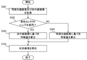
図11は、本実施形態に係る虹彩照合システム50により行われる虹彩照合処理の概略を示すフローチャートである。
ステップS201において、可視光線画像及び赤外線画像の取得が行われる。これらの画像は、後続のステップS202における着色コンタクトレンズ10の装用の有無の判定に用いられる。照合対象者の眼の赤外線画像は、図9のステップS101と同様の処理により取得される。また、可視光線照射部426及び可視光線画像取得部427により照合対象者の眼の可視光線画像の取得が行われる。可視光線照射部426は、照合対象者の眼を含む領域に可視光線を照射する。可視光線画像取得部427は、照射された可視光線の反射光に基づく可視光線画像を取得する。取得された可視光線画像は記憶部425に記憶される。
ステップS202において、判定部428は、ステップS201において取得された可視光線画像及び赤外線画像を用いて、照合対象者が着色コンタクトレンズ10を装用しているか否かを判定する。この判定は、例えば、可視光線画像と赤外線画像とを比較して、虹彩に相当する部分の差が閾値を超えているか否かに基づいて行われ得る。図5及び図6から理解されるように、着色領域110に相当する部分の模様は、可視光線画像と赤外線画像とで異なるためである。あるいは、機械学習によりあらかじめ学習を行った判別器を判定部428として用いてもよい。学習用の教師データには、着色コンタクトレンズ10を装用している場合の可視光線画像及び赤外線画像、並びに装用していない場合の可視光線画像及び赤外線画像が用いられ得る。
ステップS202において照合対象者が着色コンタクトレンズ10を装用していると判定された場合(ステップS202においてYES)には、処理はステップS203に移行する。ステップS202において照合対象者が着色コンタクトレンズ10を装用していないと判定された場合(ステップS202においてNO)には、処理はステップS204に移行する。
ステップS203において、特徴量算出部423は、赤外線画像内に含まれる虹彩の模様を用いて特徴量を算出する。算出された特徴量は、記憶部425に記憶される。
ステップS204において、特徴量算出部423は、可視光線画像内に含まれる虹彩の模様を用いて特徴量を算出する。算出された特徴量は、記憶部425に記憶される。以後の処理については第1実施形態の虹彩照合システム40と同様であるため説明を省略する。
なお、ステップS204の処理において、可視光線画像を用いて特徴量を算出することは必須ではなく、ステップS204においても赤外線画像を用いて特徴量を算出してもよい。すなわち、ステップS204の処理においては、赤外線画像又は可視光線画像のいずれを用いて特徴量を算出してもよい。例えば虹彩の模様が鮮明に表示されている画像を選んで特徴量算出処理に用いる等、状況に応じて特徴量の算出に用いる画像を変えてもよい。
以上のように、本実施形態の虹彩照合システム50は、赤外線透過性を有する着色領域を備えた着色コンタクトレンズ10を装用しているか否かを判定することができる。虹彩照合システム50は、着色コンタクトレンズ10を装用している場合には、赤外線画像による虹彩照合を行うことができ、着色コンタクトレンズ10の照合精度への影響を低減させることができる。また、虹彩照合システム50は、着色コンタクトレンズ10を装用していない場合には、例えば、可視光線画像を虹彩照合に用いることができる。この場合には、虹彩照合にどの画像を用いるかを制限する必要がないためである。したがって、処理の自由度が向上する。
上述の実施形態において説明した着色コンタクトレンズは以下の第3実施形態のようにも構成することができる。
[第3実施形態]
図12は、本実施形態に係る着色コンタクトレンズ60の平面図である。着色コンタクトレンズ60は、レンズ600と、レンズ600に形成された着色領域610とを有する。ここで、装用時において、着色領域610の少なくとも一部が装用者の虹彩と重なる位置に配されている。また、着色領域610は、赤外線透過性を有する。
図12は、本実施形態に係る着色コンタクトレンズ60の平面図である。着色コンタクトレンズ60は、レンズ600と、レンズ600に形成された着色領域610とを有する。ここで、装用時において、着色領域610の少なくとも一部が装用者の虹彩と重なる位置に配されている。また、着色領域610は、赤外線透過性を有する。
本実施形態によれば、虹彩照合の精度に対する影響を低減することができる着色コンタクトレンズを提供することができる。
上述の実施形態において説明した着色コンタクトレンズの製造方法は以下の第4実施形態のようにも構成することができる。
[第4実施形態]
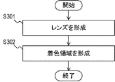
図13は、第4実施形態に係る着色コンタクトレンズの製造方法を示すフローチャートである。ステップS301において、レンズの形成が行われる。ステップS302において、レンズに着色領域が形成される。ここで、装用時において、着色領域の少なくとも一部が装用者の虹彩と重なる位置に配されている。また、着色領域は、赤外線透過性を有する。
図13は、第4実施形態に係る着色コンタクトレンズの製造方法を示すフローチャートである。ステップS301において、レンズの形成が行われる。ステップS302において、レンズに着色領域が形成される。ここで、装用時において、着色領域の少なくとも一部が装用者の虹彩と重なる位置に配されている。また、着色領域は、赤外線透過性を有する。
本実施形態によれば、虹彩照合の精度に対する影響を低減することができる着色コンタクトレンズの製造方法を提供することができる。
[変形実施形態]
本発明は、上述の実施形態に限定されることなく、本発明の趣旨を逸脱しない範囲において適宜変更可能である。
本発明は、上述の実施形態に限定されることなく、本発明の趣旨を逸脱しない範囲において適宜変更可能である。
上述の実施形態の虹彩照合システム40、50は、一例として挙げたログイン時の認証だけでなく、種々の本人確認に用いられ得る。例えば、上述の実施形態の虹彩照合システムは、空港・海港・国境における入出国のための本人確認、行政機関における本人確認、工場・事業所への入退場のための本人確認、イベント会場への入場時の本人確認等に適用され得る。
上述の各実施形態において、虹彩照合に用いられる画像の取得は、認証対象者の片目に対して行ってもよく、両目に対して行ってもよい。片目の画像のみを取得する場合、処理速度の向上、記憶容量の削減の効果があり、両目の画像を取得する場合、認証精度が向上する効果がある。
上述の実施形態の機能を実現するように該実施形態の構成を動作させるプログラムを記憶媒体に記録させ、記憶媒体に記録されたプログラムをコードとして読み出し、コンピュータにおいて実行する処理方法も各実施形態の範疇に含まれる。すなわち、コンピュータ読取可能な記憶媒体も各実施形態の範囲に含まれる。また、上述のプログラムが記録された記憶媒体だけでなく、そのプログラム自体も各実施形態に含まれる。また、上述の実施形態に含まれる1又は2以上の構成要素は、各構成要素の機能を実現するように構成されたASIC(Application Specific Integrated Circuit)、FPGA(Field Programmable Gate Array)等の回路であってもよい。
該記憶媒体としては例えばフロッピー(登録商標)ディスク、ハードディスク、光ディスク、光磁気ディスク、CD(Compact Disk)-ROM、磁気テープ、不揮発性メモリカード、ROMを用いることができる。また該記憶媒体に記録されたプログラム単体で処理を実行しているものに限らず、他のソフトウェア、拡張ボードの機能と共同して、OS(Operating System)上で動作して処理を実行するものも各実施形態の範疇に含まれる。
上述の各実施形態の機能により実現されるサービスは、SaaS(Software as a Service)の形態でユーザに対して提供することもできる。
なお、上述の実施形態は、いずれも本発明を実施するにあたっての具体化の例を示したものに過ぎず、これらによって本発明の技術的範囲が限定的に解釈されてはならないものである。すなわち、本発明はその技術思想、又はその主要な特徴から逸脱することなく、様々な形で実施することができる。
上述の実施形態の一部又は全部は、以下の付記のようにも記載されうるが、以下には限られない。
(付記1)
レンズと、
前記レンズに形成された着色領域と
を有し、
装用時において、前記着色領域の少なくとも一部が装用者の虹彩と重なる位置に配されており、
前記着色領域が赤外線透過性を有する
ことを特徴とする着色コンタクトレンズ。
レンズと、
前記レンズに形成された着色領域と
を有し、
装用時において、前記着色領域の少なくとも一部が装用者の虹彩と重なる位置に配されており、
前記着色領域が赤外線透過性を有する
ことを特徴とする着色コンタクトレンズ。
(付記2)
装用時において、前記虹彩の模様の少なくとも一部が、可視光線によっては判別できず、赤外線によっては判別できる
ことを特徴とする付記1に記載の着色コンタクトレンズ。
装用時において、前記虹彩の模様の少なくとも一部が、可視光線によっては判別できず、赤外線によっては判別できる
ことを特徴とする付記1に記載の着色コンタクトレンズ。
(付記3)
前記着色領域は、波長が750nmより大きい光に対して、透過性を有する
ことを特徴とする付記1又は2に記載の着色コンタクトレンズ。
前記着色領域は、波長が750nmより大きい光に対して、透過性を有する
ことを特徴とする付記1又は2に記載の着色コンタクトレンズ。
(付記4)
前記着色領域は、波長が750nmより大きく、1000nmより小さい光に対して、透過性を有する
ことを特徴とする付記1乃至3のいずれか1項に記載の着色コンタクトレンズ。
前記着色領域は、波長が750nmより大きく、1000nmより小さい光に対して、透過性を有する
ことを特徴とする付記1乃至3のいずれか1項に記載の着色コンタクトレンズ。
(付記5)
前記着色領域は、波長が400nm以上、750nm以下の光に対して、吸収性又は反射性を有する
ことを特徴とする付記1乃至4のいずれか1項に記載の着色コンタクトレンズ。
前記着色領域は、波長が400nm以上、750nm以下の光に対して、吸収性又は反射性を有する
ことを特徴とする付記1乃至4のいずれか1項に記載の着色コンタクトレンズ。
(付記6)
750nmより大きく、1000nmより小さい波長の光に対する前記着色領域の透過率は、400nm以上、750nm以下の波長の光に対する前記着色領域の透過率より大きい
ことを特徴とする付記1乃至5のいずれか1項に記載の着色コンタクトレンズ。
750nmより大きく、1000nmより小さい波長の光に対する前記着色領域の透過率は、400nm以上、750nm以下の波長の光に対する前記着色領域の透過率より大きい
ことを特徴とする付記1乃至5のいずれか1項に記載の着色コンタクトレンズ。
(付記7)
前記着色領域は、装用時において前記虹彩の外周を覆う位置に配されている
ことを特徴とする付記1乃至6のいずれか1項に記載の着色コンタクトレンズ。
前記着色領域は、装用時において前記虹彩の外周を覆う位置に配されている
ことを特徴とする付記1乃至6のいずれか1項に記載の着色コンタクトレンズ。
(付記8)
前記着色領域は、装用時において前記装用者の瞳孔を覆わない位置に配されている
ことを特徴とする付記7に記載の着色コンタクトレンズ。
前記着色領域は、装用時において前記装用者の瞳孔を覆わない位置に配されている
ことを特徴とする付記7に記載の着色コンタクトレンズ。
(付記9)
前記着色領域は、赤外線透過性を有する着色材料によって形成されており、
前記着色材料は、前記レンズの表面には含有されておらず、前記レンズの内部に含有されている
ことを特徴とする付記1乃至8のいずれか1項に記載の着色コンタクトレンズ。
前記着色領域は、赤外線透過性を有する着色材料によって形成されており、
前記着色材料は、前記レンズの表面には含有されておらず、前記レンズの内部に含有されている
ことを特徴とする付記1乃至8のいずれか1項に記載の着色コンタクトレンズ。
(付記10)
付記1乃至9のいずれか1項に記載の着色コンタクトレンズを装用している照合対象者の虹彩を、前記着色領域を透過する波長の赤外線を用いて撮影する赤外線画像取得部を有する
ことを特徴とする虹彩照合システム。
付記1乃至9のいずれか1項に記載の着色コンタクトレンズを装用している照合対象者の虹彩を、前記着色領域を透過する波長の赤外線を用いて撮影する赤外線画像取得部を有する
ことを特徴とする虹彩照合システム。
(付記11)
着色領域を有する着色コンタクトレンズを装用している照合対象者の虹彩を、前記着色領域を透過する波長の赤外線を用いて撮影する赤外線画像取得部と、
前記虹彩を、可視光線を用いて撮影する可視光線画像取得部と、
前記照合対象者が前記着色コンタクトレンズを装用しているか否かを判定する判定部と、
前記虹彩の照合を行う照合部と
を有し、
前記判定部が、前記照合対象者が前記着色コンタクトレンズを装用していると判定した場合には、前記照合部は、赤外線により取得された画像を用いて照合を行い、
前記判定部が、前記照合対象者が前記着色コンタクトレンズを装用していないと判定した場合には、前記照合部は、可視光線又は赤外線により取得された画像を用いて照合を行う
ことを特徴とする虹彩照合システム。
着色領域を有する着色コンタクトレンズを装用している照合対象者の虹彩を、前記着色領域を透過する波長の赤外線を用いて撮影する赤外線画像取得部と、
前記虹彩を、可視光線を用いて撮影する可視光線画像取得部と、
前記照合対象者が前記着色コンタクトレンズを装用しているか否かを判定する判定部と、
前記虹彩の照合を行う照合部と
を有し、
前記判定部が、前記照合対象者が前記着色コンタクトレンズを装用していると判定した場合には、前記照合部は、赤外線により取得された画像を用いて照合を行い、
前記判定部が、前記照合対象者が前記着色コンタクトレンズを装用していないと判定した場合には、前記照合部は、可視光線又は赤外線により取得された画像を用いて照合を行う
ことを特徴とする虹彩照合システム。
(付記12)
レンズを形成するステップと、
前記レンズに着色領域を形成するステップと
を有し、
装用時において、前記着色領域の少なくとも一部が装用者の虹彩と重なる位置に配されており、
前記着色領域が赤外線透過性を有する
ことを特徴とする着色コンタクトレンズの製造方法。
レンズを形成するステップと、
前記レンズに着色領域を形成するステップと
を有し、
装用時において、前記着色領域の少なくとも一部が装用者の虹彩と重なる位置に配されており、
前記着色領域が赤外線透過性を有する
ことを特徴とする着色コンタクトレンズの製造方法。
(付記13)
前記着色領域は、赤外線透過性を有する着色材料によって形成されており、
前記着色材料は、前記レンズの表面には含有されておらず、前記レンズの内部に含有されている
ことを特徴とする付記12に記載の着色コンタクトレンズの製造方法。
前記着色領域は、赤外線透過性を有する着色材料によって形成されており、
前記着色材料は、前記レンズの表面には含有されておらず、前記レンズの内部に含有されている
ことを特徴とする付記12に記載の着色コンタクトレンズの製造方法。
この出願は、2017年11月22日に出願された日本出願特願2017-224343を基礎とする優先権を主張し、その開示の全てをここに取り込む。
10 着色コンタクトレンズ
100 レンズ
110 着色領域
120 透明部
100 レンズ
110 着色領域
120 透明部
Claims (13)
- レンズと、
前記レンズに形成された着色領域と
を有し、
装用時において、前記着色領域の少なくとも一部が装用者の虹彩と重なる位置に配されており、
前記着色領域が赤外線透過性を有する
ことを特徴とする着色コンタクトレンズ。 - 装用時において、前記虹彩の模様の少なくとも一部が、可視光線によっては判別できず、赤外線によっては判別できる
ことを特徴とする請求項1に記載の着色コンタクトレンズ。 - 前記着色領域は、波長が750nmより大きい光に対して、透過性を有する
ことを特徴とする請求項1又は2に記載の着色コンタクトレンズ。 - 前記着色領域は、波長が750nmより大きく、1000nmより小さい光に対して、透過性を有する
ことを特徴とする請求項1乃至3のいずれか1項に記載の着色コンタクトレンズ。 - 前記着色領域は、波長が400nm以上、750nm以下の光に対して、吸収性又は反射性を有する
ことを特徴とする請求項1乃至4のいずれか1項に記載の着色コンタクトレンズ。 - 750nmより大きく、1000nmより小さい波長の光に対する前記着色領域の透過率は、400nm以上、750nm以下の波長の光に対する前記着色領域の透過率より大きい
ことを特徴とする請求項1乃至5のいずれか1項に記載の着色コンタクトレンズ。 - 前記着色領域は、装用時において前記虹彩の外周を覆う位置に配されている
ことを特徴とする請求項1乃至6のいずれか1項に記載の着色コンタクトレンズ。 - 前記着色領域は、装用時において前記装用者の瞳孔を覆わない位置に配されている
ことを特徴とする請求項7に記載の着色コンタクトレンズ。 - 前記着色領域は、赤外線透過性を有する着色材料によって形成されており、
前記着色材料は、前記レンズの表面には含有されておらず、前記レンズの内部に含有されている
ことを特徴とする請求項1乃至8のいずれか1項に記載の着色コンタクトレンズ。 - 請求項1乃至9のいずれか1項に記載の着色コンタクトレンズを装用している照合対象者の虹彩を、前記着色領域を透過する波長の赤外線を用いて撮影する赤外線画像取得部を有する
ことを特徴とする虹彩照合システム。 - 着色領域を有する着色コンタクトレンズを装用している照合対象者の虹彩を、前記着色領域を透過する波長の赤外線を用いて撮影する赤外線画像取得部と、
前記虹彩を、可視光線を用いて撮影する可視光線画像取得部と、
前記照合対象者が前記着色コンタクトレンズを装用しているか否かを判定する判定部と、
前記虹彩の照合を行う照合部と
を更に有し、
前記判定部が、前記照合対象者が前記着色コンタクトレンズを装用していると判定した場合には、前記照合部は、赤外線により取得された画像を用いて照合を行い、
前記判定部が、前記照合対象者が前記着色コンタクトレンズを装用していないと判定した場合には、前記照合部は、可視光線又は赤外線により取得された画像を用いて照合を行う
ことを特徴とする虹彩照合システム。 - レンズを形成するステップと、
前記レンズに着色領域を形成するステップと
を有し、
装用時において、前記着色領域の少なくとも一部が装用者の虹彩と重なる位置に配されており、
前記着色領域が赤外線透過性を有する
ことを特徴とする着色コンタクトレンズの製造方法。 - 前記着色領域は、赤外線透過性を有する着色材料によって形成されており、
前記着色材料は、前記レンズの表面には含有されておらず、前記レンズの内部に含有されている
ことを特徴とする請求項12に記載の着色コンタクトレンズの製造方法。
Priority Applications (7)
| Application Number | Priority Date | Filing Date | Title |
|---|---|---|---|
| CN201880075547.4A CN111386490A (zh) | 2017-11-22 | 2018-09-14 | 着色隐形眼镜、着色隐形眼镜的制造方法及虹膜识别系统 |
| JP2019556112A JP7169575B2 (ja) | 2017-11-22 | 2018-09-14 | 着色コンタクトレンズ、着色コンタクトレンズの製造方法及び虹彩照合システム |
| EP18880092.4A EP3715938A4 (en) | 2017-11-22 | 2018-09-14 | COLORED CONTACT LENS, METHOD OF MANUFACTURING A COLORED CONTACT LENS, AND IRIS SNACKING SYSTEM |
| US16/646,868 US20200371381A1 (en) | 2017-11-22 | 2018-09-14 | Colored contact lens, manufacturing method of colored contact lens, and iris recognition system |
| JP2021170766A JP7294382B2 (ja) | 2017-11-22 | 2021-10-19 | 着色コンタクトレンズ、着色コンタクトレンズの製造方法及び虹彩照合システム |
| US17/683,539 US12061381B2 (en) | 2017-11-22 | 2022-03-01 | Colored contact lens, manufacturing method of colored contact lens, and iris recognition system |
| US17/683,550 US11977279B2 (en) | 2017-11-22 | 2022-03-01 | Colored contact lens, manufacturing method of colored contact lens, and iris recognition system |
Applications Claiming Priority (2)
| Application Number | Priority Date | Filing Date | Title |
|---|---|---|---|
| JP2017-224343 | 2017-11-22 | ||
| JP2017224343 | 2017-11-22 |
Related Child Applications (3)
| Application Number | Title | Priority Date | Filing Date |
|---|---|---|---|
| US16/646,868 A-371-Of-International US20200371381A1 (en) | 2017-11-22 | 2018-09-14 | Colored contact lens, manufacturing method of colored contact lens, and iris recognition system |
| US17/683,550 Continuation US11977279B2 (en) | 2017-11-22 | 2022-03-01 | Colored contact lens, manufacturing method of colored contact lens, and iris recognition system |
| US17/683,539 Continuation US12061381B2 (en) | 2017-11-22 | 2022-03-01 | Colored contact lens, manufacturing method of colored contact lens, and iris recognition system |
Publications (1)
| Publication Number | Publication Date |
|---|---|
| WO2019102697A1 true WO2019102697A1 (ja) | 2019-05-31 |
Family
ID=66630592
Family Applications (1)
| Application Number | Title | Priority Date | Filing Date |
|---|---|---|---|
| PCT/JP2018/034288 Ceased WO2019102697A1 (ja) | 2017-11-22 | 2018-09-14 | 着色コンタクトレンズ、着色コンタクトレンズの製造方法及び虹彩照合システム |
Country Status (5)
| Country | Link |
|---|---|
| US (3) | US20200371381A1 (ja) |
| EP (1) | EP3715938A4 (ja) |
| JP (2) | JP7169575B2 (ja) |
| CN (1) | CN111386490A (ja) |
| WO (1) | WO2019102697A1 (ja) |
Families Citing this family (2)
| Publication number | Priority date | Publication date | Assignee | Title |
|---|---|---|---|---|
| JP7169575B2 (ja) | 2017-11-22 | 2022-11-11 | 日本電気株式会社 | 着色コンタクトレンズ、着色コンタクトレンズの製造方法及び虹彩照合システム |
| USD1075870S1 (en) * | 2020-03-26 | 2025-05-20 | Ohio State Innovation Foundation | Contact lens |
Citations (8)
| Publication number | Priority date | Publication date | Assignee | Title |
|---|---|---|---|---|
| US4952046A (en) * | 1982-02-26 | 1990-08-28 | Stephens James B | Optical lenses with selective transmissivity functions |
| JP2001076072A (ja) * | 1999-09-02 | 2001-03-23 | Oki Electric Ind Co Ltd | 個体識別システム |
| JP2001517324A (ja) * | 1997-03-31 | 2001-10-02 | パラガン、ヴィジァン、サイエンセズ、インク | 光濾波性コンタクトレンズ |
| JP2002279402A (ja) * | 2001-03-22 | 2002-09-27 | Oki Electric Ind Co Ltd | コンタクトレンズ辞書作成装置および個人認証システム |
| WO2014125742A1 (ja) | 2013-02-14 | 2014-08-21 | 株式会社メニコンネクト | 着色コンタクトレンズ |
| JP2015504691A (ja) * | 2011-12-02 | 2015-02-16 | アキュフォーカス・インコーポレーテッド | 選択的分光透過性を有する眼科マスク |
| JP2017515822A (ja) * | 2014-05-05 | 2017-06-15 | フロンティア サイエンティフィック インコーポレイテッドFrontier Scientific,Inc. | 選択的ブルーライトフィルターされた光学レンズ用の光安定性および熱安定性の染料化合物 |
| JP2017224343A (ja) | 2014-09-18 | 2017-12-21 | 日本電気株式会社 | 情報処理装置、方法、およびプログラム |
Family Cites Families (26)
| Publication number | Priority date | Publication date | Assignee | Title |
|---|---|---|---|---|
| JPS5862601A (ja) * | 1981-10-09 | 1983-04-14 | Sumitomo Electric Ind Ltd | 被覆光フアイバ− |
| FI842084L (fi) | 1983-05-25 | 1984-11-26 | Neefe Charles W | Kosmetisk kontaktlins. |
| US4582402A (en) | 1984-04-16 | 1986-04-15 | Schering Corporation | Color-imparting contact lenses |
| US4867552A (en) | 1986-02-24 | 1989-09-19 | Sunsoft Corp. | Eye color change contact lens |
| US4738520A (en) | 1986-02-24 | 1988-04-19 | Neefe Charles W | Eye color change contact lens |
| JPH062335U (ja) | 1992-06-19 | 1994-01-14 | 由美 鈴木 | コンタクトレンズ |
| US5617154A (en) | 1994-10-28 | 1997-04-01 | Flexlens | Light filtering contact lens |
| US6164777A (en) * | 1998-12-16 | 2000-12-26 | Bausch & Lomb Incorporated | Color-imparting contact lenses with interference coating and method for making the same |
| JP2005041023A (ja) | 2003-07-24 | 2005-02-17 | Konica Minolta Photo Imaging Inc | 個人認証カード |
| JP2005266538A (ja) * | 2004-03-19 | 2005-09-29 | Stanley Electric Co Ltd | 赤外線透過フィルタ |
| JP4561248B2 (ja) | 2004-09-01 | 2010-10-13 | 凸版印刷株式会社 | 偽造防止媒体の認証方法 |
| KR100497623B1 (ko) * | 2004-12-21 | 2005-07-01 | (주)브이씨티 | 램프히터의 근적외선 투과용 다층 박막 증착 시스템 및 그 방법 |
| MY161660A (en) * | 2005-05-04 | 2017-04-28 | Novartis Ag | Automated inspection of colored contact lenses |
| US7712901B2 (en) | 2006-12-08 | 2010-05-11 | Predictek, Inc. | Method and apparatus for diagnosing conditions of the eye with infrared light |
| EP2634728A1 (en) * | 2010-10-29 | 2013-09-04 | Antonov, Dimitry Evgenievich | Iris identification method of a person (alternatives) |
| JP5816862B2 (ja) | 2011-07-21 | 2015-11-18 | パナソニックIpマネジメント株式会社 | スイッチ装置 |
| JP6196014B2 (ja) | 2011-08-30 | 2017-09-13 | サターン ライセンシング エルエルシーSaturn Licensing LLC | シャッター眼鏡装置 |
| WO2013094073A1 (ja) | 2011-12-22 | 2013-06-27 | 株式会社メニコン | 美容コンタクトレンズ |
| WO2014087557A1 (ja) | 2012-12-07 | 2014-06-12 | パナソニック株式会社 | 家具ユニット |
| US9934436B2 (en) * | 2014-05-30 | 2018-04-03 | Leidos Innovations Technology, Inc. | System and method for 3D iris recognition |
| US20160019420A1 (en) * | 2014-07-15 | 2016-01-21 | Qualcomm Incorporated | Multispectral eye analysis for identity authentication |
| US9412029B2 (en) * | 2014-12-12 | 2016-08-09 | Iris Id, Inc. | Apparatus for recognizing iris and operating method thereof |
| CN104793349B (zh) * | 2015-01-29 | 2017-09-19 | 广州琦安琦视觉科技有限公司 | 一种具有防紫外线、衍射光及蓝光多功能隐形眼镜 |
| JP2016166109A (ja) | 2015-03-10 | 2016-09-15 | パナソニックIpマネジメント株式会社 | タッチセンサー付きガラスパネルおよびディスプレイ装置 |
| CN205982876U (zh) * | 2016-08-18 | 2017-02-22 | 北京中科虹霸科技有限公司 | 适于虹膜识别光照透射的美容隐形眼镜 |
| JP7169575B2 (ja) | 2017-11-22 | 2022-11-11 | 日本電気株式会社 | 着色コンタクトレンズ、着色コンタクトレンズの製造方法及び虹彩照合システム |
-
2018
- 2018-09-14 JP JP2019556112A patent/JP7169575B2/ja active Active
- 2018-09-14 WO PCT/JP2018/034288 patent/WO2019102697A1/ja not_active Ceased
- 2018-09-14 US US16/646,868 patent/US20200371381A1/en not_active Abandoned
- 2018-09-14 CN CN201880075547.4A patent/CN111386490A/zh active Pending
- 2018-09-14 EP EP18880092.4A patent/EP3715938A4/en not_active Withdrawn
-
2021
- 2021-10-19 JP JP2021170766A patent/JP7294382B2/ja active Active
-
2022
- 2022-03-01 US US17/683,539 patent/US12061381B2/en active Active
- 2022-03-01 US US17/683,550 patent/US11977279B2/en active Active
Patent Citations (8)
| Publication number | Priority date | Publication date | Assignee | Title |
|---|---|---|---|---|
| US4952046A (en) * | 1982-02-26 | 1990-08-28 | Stephens James B | Optical lenses with selective transmissivity functions |
| JP2001517324A (ja) * | 1997-03-31 | 2001-10-02 | パラガン、ヴィジァン、サイエンセズ、インク | 光濾波性コンタクトレンズ |
| JP2001076072A (ja) * | 1999-09-02 | 2001-03-23 | Oki Electric Ind Co Ltd | 個体識別システム |
| JP2002279402A (ja) * | 2001-03-22 | 2002-09-27 | Oki Electric Ind Co Ltd | コンタクトレンズ辞書作成装置および個人認証システム |
| JP2015504691A (ja) * | 2011-12-02 | 2015-02-16 | アキュフォーカス・インコーポレーテッド | 選択的分光透過性を有する眼科マスク |
| WO2014125742A1 (ja) | 2013-02-14 | 2014-08-21 | 株式会社メニコンネクト | 着色コンタクトレンズ |
| JP2017515822A (ja) * | 2014-05-05 | 2017-06-15 | フロンティア サイエンティフィック インコーポレイテッドFrontier Scientific,Inc. | 選択的ブルーライトフィルターされた光学レンズ用の光安定性および熱安定性の染料化合物 |
| JP2017224343A (ja) | 2014-09-18 | 2017-12-21 | 日本電気株式会社 | 情報処理装置、方法、およびプログラム |
Also Published As
| Publication number | Publication date |
|---|---|
| JPWO2019102697A1 (ja) | 2020-11-19 |
| US20200371381A1 (en) | 2020-11-26 |
| JP7294382B2 (ja) | 2023-06-20 |
| US20220187624A1 (en) | 2022-06-16 |
| JP2022009232A (ja) | 2022-01-14 |
| EP3715938A1 (en) | 2020-09-30 |
| US20220187623A1 (en) | 2022-06-16 |
| EP3715938A4 (en) | 2021-01-13 |
| US12061381B2 (en) | 2024-08-13 |
| JP7169575B2 (ja) | 2022-11-11 |
| CN111386490A (zh) | 2020-07-07 |
| US11977279B2 (en) | 2024-05-07 |
Similar Documents
| Publication | Publication Date | Title |
|---|---|---|
| CN110889320B (zh) | 眼周面部识别切换 | |
| KR102362651B1 (ko) | 얼굴 인식에 사용되는 템플릿들을 업데이트하기 위한 프로세스 | |
| US10719692B2 (en) | Vein matching for difficult biometric authentication cases | |
| JP7279751B2 (ja) | 虹彩照合システム、虹彩照合方法及び記憶媒体 | |
| JP7298720B2 (ja) | 画像処理システム、画像処理方法及び記憶媒体 | |
| JP7351375B2 (ja) | 虹彩照合システム、虹彩照合方法及び記憶媒体 | |
| JP7226477B2 (ja) | 情報処理システム、情報処理方法及び記憶媒体 | |
| US20160019420A1 (en) | Multispectral eye analysis for identity authentication | |
| JP7294382B2 (ja) | 着色コンタクトレンズ、着色コンタクトレンズの製造方法及び虹彩照合システム | |
| US20230280601A1 (en) | Colored contact lens, manufacturing method of colored contact lens, and iris recognition system | |
| CN120112964A (zh) | 作为安全特征的距离 | |
| JPWO2020121520A1 (ja) | 画像処理装置、認証システム、画像処理方法、認証方法、及び、プログラム | |
| FR3148486A1 (fr) | Dispositif à usage sécurisé par reconnaissance d'image |
Legal Events
| Date | Code | Title | Description |
|---|---|---|---|
| 121 | Ep: the epo has been informed by wipo that ep was designated in this application |
Ref document number: 18880092 Country of ref document: EP Kind code of ref document: A1 |
|
| ENP | Entry into the national phase |
Ref document number: 2019556112 Country of ref document: JP Kind code of ref document: A |
|
| NENP | Non-entry into the national phase |
Ref country code: DE |
|
| ENP | Entry into the national phase |
Ref document number: 2018880092 Country of ref document: EP Effective date: 20200622 |