WO2019102862A1 - グリッパ、把持装置及び産業用ロボット - Google Patents
グリッパ、把持装置及び産業用ロボット Download PDFInfo
- Publication number
- WO2019102862A1 WO2019102862A1 PCT/JP2018/041512 JP2018041512W WO2019102862A1 WO 2019102862 A1 WO2019102862 A1 WO 2019102862A1 JP 2018041512 W JP2018041512 W JP 2018041512W WO 2019102862 A1 WO2019102862 A1 WO 2019102862A1
- Authority
- WO
- WIPO (PCT)
- Prior art keywords
- palm
- gripper
- palm portion
- case
- high strength
- Prior art date
- Legal status (The legal status is an assumption and is not a legal conclusion. Google has not performed a legal analysis and makes no representation as to the accuracy of the status listed.)
- Ceased
Links
Images




Classifications
-
- B—PERFORMING OPERATIONS; TRANSPORTING
- B25—HAND TOOLS; PORTABLE POWER-DRIVEN TOOLS; MANIPULATORS
- B25J—MANIPULATORS; CHAMBERS PROVIDED WITH MANIPULATION DEVICES
- B25J15/00—Gripping heads and other end effectors
- B25J15/08—Gripping heads and other end effectors having finger members
-
- B—PERFORMING OPERATIONS; TRANSPORTING
- B25—HAND TOOLS; PORTABLE POWER-DRIVEN TOOLS; MANIPULATORS
- B25J—MANIPULATORS; CHAMBERS PROVIDED WITH MANIPULATION DEVICES
- B25J15/00—Gripping heads and other end effectors
- B25J15/0023—Gripper surfaces directly activated by a fluid
-
- B—PERFORMING OPERATIONS; TRANSPORTING
- B25—HAND TOOLS; PORTABLE POWER-DRIVEN TOOLS; MANIPULATORS
- B25J—MANIPULATORS; CHAMBERS PROVIDED WITH MANIPULATION DEVICES
- B25J15/00—Gripping heads and other end effectors
- B25J15/0028—Gripping heads and other end effectors with movable, e.g. pivoting gripping jaw surfaces
-
- B—PERFORMING OPERATIONS; TRANSPORTING
- B25—HAND TOOLS; PORTABLE POWER-DRIVEN TOOLS; MANIPULATORS
- B25J—MANIPULATORS; CHAMBERS PROVIDED WITH MANIPULATION DEVICES
- B25J15/00—Gripping heads and other end effectors
- B25J15/06—Gripping heads and other end effectors with vacuum or magnetic holding means
- B25J15/0616—Gripping heads and other end effectors with vacuum or magnetic holding means with vacuum
- B25J15/0625—Gripping heads and other end effectors with vacuum or magnetic holding means with vacuum provided with a valve
-
- B—PERFORMING OPERATIONS; TRANSPORTING
- B25—HAND TOOLS; PORTABLE POWER-DRIVEN TOOLS; MANIPULATORS
- B25J—MANIPULATORS; CHAMBERS PROVIDED WITH MANIPULATION DEVICES
- B25J15/00—Gripping heads and other end effectors
- B25J15/08—Gripping heads and other end effectors having finger members
- B25J15/12—Gripping heads and other end effectors having finger members with flexible finger members
-
- B—PERFORMING OPERATIONS; TRANSPORTING
- B25—HAND TOOLS; PORTABLE POWER-DRIVEN TOOLS; MANIPULATORS
- B25J—MANIPULATORS; CHAMBERS PROVIDED WITH MANIPULATION DEVICES
- B25J11/00—Manipulators not otherwise provided for
- B25J11/0045—Manipulators used in the food industry
Definitions
- the present invention relates to a gripper, a gripping device and an industrial robot.
- a gripping device intended to grip a work there are a palm portion, and a plurality of finger portions provided protruding around the palm portion, which are tipped toward the palm portion by deforming the palm portion in the thickness direction
- grip apparatus provided with the bag-like holding body which has and the granular material accommodated in the holding body is disclosed (patent document 1). By depressurizing the inside of the grip main body, the palm portion deforms in the thickness direction, and the finger portion elastically deforms so as to fall toward the palm portion.
- this gripping device Since this gripping device has a plurality of fingers, it can hold workpieces of different sizes and shapes in a versatile manner, and can be gripped only by depressurizing the inside of the gripping body, so control is simple, and the gripping body Since it is not necessary to press firmly against the work, it is possible to grip a flexible work such as food without damaging it.
- the gripping device of Patent Document 1 has a problem that when the gripping body ruptures due to deterioration, breakage, or the like, powder particles filled in the gripping body scatter and contaminate the work.
- the granular material is deteriorated by the density change associated with the Jamming transition, so there is a problem that it can not be used stably.
- An object of the present invention is to provide a gripper, a gripping device, and an industrial robot that can grip a workpiece more reliably without using particulate matter.
- the gripper according to the present invention is provided with a palm portion, and a plurality of finger portions which are provided protruding around the palm portion and which fall toward the palm portion by deforming the palm portion in the thickness direction, and the finger portions Is formed on a side opposite to the side on which the outer side of the palm portion is formed, and is provided between a connection portion connected to the case, the palm portion and the connection portion, from the outer edge of the palm portion It has a predetermined length in the thickness direction of the palm portion and is integrally formed with a high strength portion which is less likely to be deformed than the palm portion.
- a gripping device comprises the gripper and the case connected to the connecting portion.
- the industrial robot according to the present invention is provided with the above-mentioned gripping device.
- the high-strength portion prevents the outer periphery of the palm portion from contracting, and the palm portion is deformed in the thickness direction, thereby deforming the finger portion toward the palm portion and gripping the work. Therefore, the workpiece can be held more reliably without using powder. Since the high strength portion is integrally formed with the palm portion and the finger portion, the finger portion deforms continuously and gently. Therefore, the gripping device can softly grip the workpiece.
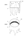
- FIG. 10A is a partial end view
- FIG. 10B is a perspective view.
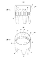
- FIG. 11A is a longitudinal cross-sectional view
- FIG. 11B is a perspective view.
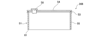
- It is a longitudinal cross-sectional view which shows the structure of the case which concerns on a modification.
- the gripper according to the present invention is provided with a palm portion, and a plurality of finger portions which are provided protruding around the palm portion and which fall toward the palm portion by deforming the palm portion in the thickness direction, and the finger portions Is formed on a side opposite to the side on which the outer side of the palm portion is formed, and is provided between a connection portion connected to the case, the palm portion and the connection portion, from the outer edge of the palm portion It has a predetermined length in the thickness direction of the palm portion and is integrally formed with a high strength portion which is less likely to be deformed than the palm portion.
- the high strength portion is less likely to be deformed than the palm portion, when the pressure is reduced on the inner surface side of the palm portion, the palm portion is deformed in the thickness direction without the outer periphery contracting. Therefore, since the gripper elastically deforms so that the finger portion falls toward the palm portion, it is possible to grip the work more reliably without using powder and granular material.
- the high strength part is a constant area between the connection part and the palm part.
- the high strength portion is formed to have higher mechanical strength than the palm portion.
- the high strength portion includes the case where the high strength portion is uniformly provided around the palm portion and the case where the high strength portion is partially provided.
- the high strength portion may be thicker than the palm portion.
- the thickness of the high strength portion is not limited to uniform, but may be partially thick.
- the partially thick case includes the case of being partially in the circumferential direction of the palm portion and the case of being partially in the direction parallel to the thickness direction of the palm portion.
- the high strength portion may be formed of a material having higher mechanical strength than the palm portion. Materials having high mechanical strength include, in the case of a material having the same quality as the palm but having high hardness, the case of the palm and different materials, the case of including an additive such as a filler, and the case of their composite.
- the high strength portion contacts a portion of the case at the proximal end.
- the high strength portion includes the case of surface contact with the case at the proximal end and the case of line contact.
- the proximal end preferably has a contact surface in contact with the case.
- the case comprises an upper case and a lower case
- the upper case may be in contact with the contact surface
- the lower case may be in contact with the contact surface.
- the high strength portion is a constant region from the proximal end to the distal end connected to the palm portion.
- the tip is the boundary between the high strength portion and the palm portion, but is not limited to the case where it can be clearly recognized.
- the tip is preferably a fulcrum when the palm is deformed in the thickness direction.
- FIG. 1 shows the configuration of an industrial robot 12 to which the gripping device 10 according to the present embodiment is applied.
- the industrial robot 12 is an orthogonal robot, and includes a rail 14, a moving body 16 moving along the rail 14, and an air cylinder 18 fixed to the moving body 16.
- the rail 14 is provided movably in the Y-axis direction in the drawing.
- the air cylinder 18 has a cylinder tube 19 and a piston rod 20 provided so as to be movable back and forth relative to the cylinder tube 19.
- the cylinder tube 19 is provided with pipings 21 and 22.
- the piston rod 20 can be advanced and retracted with respect to the cylinder tube 19 by supplying and discharging gas through the pipes 21 and 22.
- a gripping device 10 is provided at the tip of the piston rod 20.
- the industrial robot 12 can hold the work W placed on the horizontal base 26 with the holding device 10 and move the work W in the X-axis, Y-axis, and Z-axis directions.
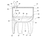
- the gripping device 10 includes a case 36A connected to the piston rod 20 and a gripper 28A fixed to the case 36A.
- a pipe 24 is connected to the case 36A.
- the gripper 28A can be formed of a material having air tightness and elasticity, such as natural rubber or synthetic rubber.
- the hardness of the gripper 28A measured according to the durometer hardness test (type A) of JIS K6253 is preferably about 60 to 90.
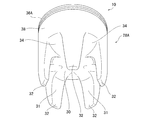
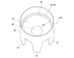
- the gripper 28 ⁇ / b> A includes a palm portion 30 and a plurality of finger portions 32 provided to protrude around the palm portion 30.
- the palm portion 30 has a substantially disc shape.
- the finger portions 32 are integrally formed with the palm portion 30, and five pieces of the finger portions 32 are radially provided so as to surround the palm portion 30. A predetermined interval is formed between the finger portions 32.
- the inner surface of the finger portion 32 is integrally formed with the palm portion 30.
- the external shape of the finger portion 32 can be appropriately selected, and may be, for example, a cylinder, a cone, a truncated cone, a triangular prism, a quadrangular prism, a triangular pyramid, a quadrangular pyramid, a quadrangular pyramid, a rectangular parallelepiped, or the like.
- the finger portions 32 are configured in the same shape.
- the plurality of finger portions 32 need not all have the same shape, and may have different shapes.
- the finger portion 32 has a quadrangular frustum shape, and the inner surface is formed to be inclined outward from the proximal end joined to the palm portion 30 toward the distal end.
- a connecting portion 38 is integrally formed at a position surrounding the outer edge of the palm portion 30 opposite to the side on which the finger portion 32 is formed.
- the connection portion 38 is cylindrical, and in the case of this figure, has a circular opening at the upper end.
- the fingers 32 are solid.
- the material of the finger portion 32 may be the same as or different from that of the other portions (the palm portion 30 and the connection portion 38), and it is not necessary to be even. Composite materials combining different materials, additives such as fillers, etc. May be included.
- the opening of the gripper 28A is sealed by a case 36A.
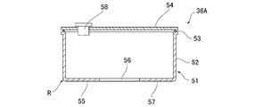
- the case 36A is preferably made of metal such as stainless steel or hard resin such as plastic, and has a lower case 51 and an upper case 54.
- the lower case 51 has a bottom portion 57 having a through hole 56 at the center, and a cylindrical portion 52 integrally formed on the outer edge of the bottom portion 57.
- the outer edge R of the bottom surface 55 which is the tip surface of the lower case 51 is chamfered. In the chamfering process, an outer edge of the bottom surface 55 is cut to make a square surface or a round surface.
- the size of the chamfering process is preferably smaller in order to prevent the connection portion 38 from locally deforming in the thickness direction.
- the upper case 54 is a disk-like member and has a joint 58 provided to penetrate in the thickness direction.
- One end of a pipe 24 is connected to the joint 58 (FIG. 3).
- the other end of the pipe 24 is connected to a vacuum pump via, for example, a three-way valve.
- the three-way valve has a vacuum port, an air supply / discharge port, an air release port, and the vacuum port is connected to a vacuum pump, the air supply / discharge port is connected to the gripping device 10, and the air release port is connected to the outside. Gas flows from inside to outside of the gripper 28A and from inside to outside of the gripper 28A through the piping 24.
- the lower case 51 and the upper case 54 are integrated at the upper end of the cylindrical portion 52 via an O-ring 53 as a sealing material. Between the bottom surface of the lower case 51 and the inner surface of the palm portion 30, a guide space 40 for receiving the palm portion 30 deformed in the thickness direction is formed.
- the gripper 28 ⁇ / b> A includes a high strength portion 42 which is less likely to be deformed in the thickness direction than the palm portion 30 between the connection portion 38 and the palm portion 30.
- the high strength portion 42 is integrally formed with the palm portion 30 and the connection portion 38.
- the high strength portion 42 has a proximal end 44 in contact with the lower case 51, and a distal end 43 separated from the proximal end 44 toward the finger portion 32 and connected to the palm portion 30.
- the high strength portion 42 is less deformed than the palm portion 30, but is not a perfect rigid body, and is microscopically deformed toward the center of the palm portion 30 with the proximal end 44 as a fulcrum.
- the base end 44 is provided at a position away from the outer edge of the palm portion 30 in the thickness direction of the palm portion 30, that is, at a position away from the palm portion 30 to the upper opening side of the connection portion 38.
- the proximal end 44 has a contact surface 45 that contacts the outer peripheral portion of the bottom surface 55 of the case 36A.
- the high strength portion 42 has an inner circumferential surface 46 in contact with the guide space 40 on the center side of the palm 30 continuous with the contact surface 45.
- the inside of the palm portion 30 has a substantially flat inner surface 48 and a curved surface 50 provided on the periphery of the inner surface 48 and convex outward.
- the inner circumferential surface 46 and the inner surface 48 of the palm portion 30 are connected by a curved surface 50.
- the tip 43 of the high strength portion 42 is disposed between the inner circumferential surface 46 and the curved surface 50.
- the tip 43 is a fulcrum when the palm 30 is deformed in the thickness direction.
- the high strength portion 42 is formed to conform to the shape of the connection portion 38 so as to surround the periphery of the palm portion 30, and in the case of FIG.
- the contact surface 45 is an upper surface of the high strength portion 42.
- the entire circumference of the outer peripheral portion of the bottom surface 55 of the case 36A contacts the contact surface 45 of the high strength portion 42.
- the entire circumference is not necessarily limited to the case where it is the entire circumference of a complete outer peripheral portion, and includes the case where there is a portion that is not in slight contact.
- the industrial robot 12 positions the gripping device 10 on the vertical line of the workpiece W placed on the base 26 by moving the movable body 16 along the rail 14 (FIG. 1). Next, the industrial robot 12 extends the air cylinder 18 until the finger 32 reaches the side surface of the work W by the piston rod 20 advancing from the cylinder tube 19.
- the three-way valve is then switched to the state in which the air release port is shut off and the air supply and exhaust port is in communication with the vacuum port.
- the gripping device 10 sucks the gas in the gripper 28A through the pipe 24, and reduces the pressure in the gripper 28A to -0.03 MPa or less.
- the grippers 28A maintain the shape in the high strength portion 42. Then, the palm portion 30 is deformed in the thickness direction so as to be sucked into the guide space 40 (FIG. 6). As the palm portion 30 deforms in the thickness direction, the inner surface of the finger portion 32 is pulled to the center of the palm portion 30. Then, the finger 32 elastically deforms so as to fall toward the palm 30. Thereby, the inner surface 31 of the finger portion 32 mainly contacts the surface of the workpiece W.
- the high strength portion 42 is microscopically elastically deformed with the proximal end 44 as a fulcrum in accordance with the deformation of the palm portion 30.
- the finger portion 32 contacts the side surface of the workpiece W.
- the gripping device 10 grips the workpiece W by depressurizing the inside of the gripper 28A.
- the gripping device 10 exerts a gripping force corresponding to the pressure in the gripper 28A. That is, the gripping force of the gripping device 10 becomes larger as the pressure in the gripper 28A is lower.
- the industrial robot 12 can lift the work W from the base 26 by retracting the piston rod 20 into the cylinder tube 19 and contracting the air cylinder 18. Further, the industrial robot 12 can freely move the work W in the horizontal direction by moving the movable body 16 along the rails 14 or moving the rails 14 in the Y-axis direction.
- the industrial robot 12 After moving to the desired location, the industrial robot 12 extends the air cylinder 18 until the workpiece W contacts the base 26 by the piston rod 20 advancing out of the cylinder tube 19.
- the three-way valve is then switched to the state where the vacuum port is shut off and the air supply and exhaust port is in communication with the air release port.
- gas flows into the gripper 28A from the air release port through the pipe 24.
- the palm portion 30 As the pressure in the gripper 28A returns to the atmospheric pressure, the palm portion 30 is pushed out of the guide hole and returns to the original state.
- the finger unit 32 opens and releases the work W.
- the industrial robot 12 retracts the piston rod 20 into the cylinder tube 19 and contracts the air cylinder 18 to separate the gripping device 10 from the workpiece W.
- the industrial robot 12 can move the workpiece W placed on the base 26 to a desired position by gripping the workpiece W with the gripping device 10.
- the high strength portion 42 prevents the outer periphery of the palm portion 30 from contracting, so that the finger portion 32 is deformed toward the palm portion 30 by the palm portion 30 being deformed in the thickness direction. Therefore, the gripping device 10 can grip the workpiece W more reliably without using powder. Since the gripping device 10 does not use powder or granular material, the workpiece W is not contaminated even if the gripper 28A ruptures.
- the gripper 28A does not use a powder or granular material, the workpiece W can be similarly grasped not only when the tip end of the finger portion 32 is in the downward direction, but also in the sideways or upward state. Therefore, the gripping device 10 can not only lift the workpiece W on the base 26, but also grip the workpiece W suspended on a vertical wall surface or a ceiling.
- the finger portion 32 is higher in rigidity than the powder after Jamming transition, so the workpiece W can be gripped more reliably.
- the gripping device 10 can grip the workpiece W by depressurizing the grippers 28A and reliably deforming the palm portion 30 in the thickness direction, so there is no need to press the grippers 28A against the workpiece W. Therefore, since the holding device 10 can hold the soft work W such as food without crushing it, the work W can be prevented from being damaged.
- the gripper 28A can change the amount of deformation of the finger portion 32 and the gripping force according to the degree of pressure reduction inside. Therefore, the gripping device 10 can change the gripping force in accordance with the size and hardness of the workpiece W, so that the versatility can be improved. Since the palm portion 30 is deformed in the thickness direction so as to be sucked into the guide space 40, the finger portion 32 is deformed to a more acute angle toward the palm portion 30. Thus, the gripping device 10 can also grip smaller workpieces W.
- the high strength portion 42 is integrally formed with the palm portion 30 and the finger portion 32, and microscopically deforms in accordance with the deformation of the palm portion 30 in the thickness direction. As a result, the fingers 32 are deformed continuously and gently by the deformation of the palm 30. Therefore, the gripping device 10 can grip the workpiece W softly. Incidentally, in the gripper 28A which does not have the high strength portion 42, the finger portion 32 deforms so as to buckle.
- the gripper 28A can reduce the number of parts and the number of manufacturing steps because the palm portion 30, the finger portion 32, the high strength portion 42, and the connection portion 38 are integrally formed. By integrally forming the palm portion 30 and the high strength portion 42 to which more load is applied at the time of pressure reduction, breakage of the gripper 28A can be prevented, and durability can be improved.
- the gripper 28B shown in FIG. 7 differs from the above embodiment in that a curved surface that is convex outward is provided between the contact surface 62 of the high strength portion 60 and the inner surface of the connection portion 38. Since the mechanical strength of the connection portion 38 at the position corresponding to the tip of the case 36A is increased by having the curved surface that is convex outward between the contact surface 62 and the inner surface of the connection portion 38 in this manner, the portion is localized Deformation in the thickness direction can be prevented. By preventing the local deformation of the connection portion 38, the finger portion 32 can be uniformly deformed, so that the gripper 28B can grip the workpiece W more reliably. When the connecting portion 38 at a position corresponding to the tip of the case 36A is locally deformed, the gripper is displaced with respect to the case 36A at the time of pressure reduction, and as a result, the finger portion 32 is not easily deformed uniformly.
- the high strength portion 69 of the gripper 28C shown in FIGS. 8 and 9 is provided with a plurality of strip members 64 at positions corresponding to the finger portions 32.
- the band 64 is the same five as the finger portion 32.
- the band 64 is evenly disposed at a position around the palm portion 30 and at the proximal end of the finger portion 32.
- the strip 64 has a contact surface 63 on the upper surface and an inner circumferential surface 65 on the inner surface on the palm portion 30 side.
- the tip 49 of the high strength portion 69 is disposed between the inner circumferential surface 65 and the curved surface 50. The tip 49 is a fulcrum when the palm 30 is deformed in the thickness direction.
- the gripper 28C shown in this figure has the high strength portion 69, whereby the same effect as the above embodiment can be obtained.
- the high-strength portion 69 of the present modification can reduce the material between the strip-like members 64 as compared with the case of annular formation, and weight reduction can be achieved accordingly.
- the high strength portion 66 of the gripper 28D shown in FIGS. 10A and 10B has a plurality of annular convex portions 67.
- the annular convex portions 67 are arranged in parallel with the thickness direction of the palm portion 30 at predetermined intervals.
- the upper surface of the convex portion 67 located at the position farthest from the palm portion 30 is the contact surface 68.
- the inner surface on the palm portion 30 side of the convex portion 67 is the inner peripheral surface 70.
- a flat surface is formed between the inner circumferential surface 70 and the inner surface 48 of the palm portion 30.
- the entire periphery of the outer peripheral portion of the bottom surface 55 of the case 36A contacts the contact surface 68 of the high strength portion 66.
- the gripper 28D shown in this figure has the high strength portion 66, so that the same effect as the above embodiment can be obtained.
- the high strength portion 74 of the gripper 28E shown in FIGS. 11A and 11B has a plurality of ridges 79 whose longitudinal direction is the thickness direction of the palm portion 30.
- the ridges 79 are arranged around the palm portion 30 at predetermined intervals.
- the upper surface of the ridge 79 is the contact surface 76
- the inner surface of the ridge 79 on the palm portion 30 side is the inner circumferential surface 78.
- a flat surface is formed between the inner circumferential surface 78 and the inner surface 48 of the palm portion 30.
- a part of the outer peripheral portion of the bottom surface 55 of the case 36A contacts the contact surface 76 of the high strength portion 74.
- the gripper 28E shown in this figure has the high strength portion 74, so that the same effect as that of the above embodiment can be obtained.
- the high strength portion 82 of the gripper 28F shown in FIG. 12 is formed of a material having higher mechanical strength than the palm portion 30.
- the proximal end of the high strength portion 82 is a portion 84 in contact with the distal end of the case 36A.
- the tip 86 of the high strength portion 82 which is an interface with the palm portion 30 serves as a fulcrum when the palm portion 30 is deformed in the thickness direction.
- the inner circumferential surface 87 on the palm portion 30 side of the high strength portion 82 is gently continuous with the curved surface 50.
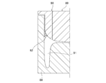
- the gripper 28F shown in this figure can be manufactured by insert molding as shown in FIG.
- a mold including a lower mold 88 provided with a concave portion 91 having the shape of the finger portion 32 and an upper mold 89 provided with a convex portion having the shape of the guide space 40 is used.
- the upper die 89 is mounted on the lower die 88 by disposing at a predetermined position a high strength portion 82 formed in advance from a predetermined material, for example, a resin material having a hardness higher than that of the material forming the palm portion 30 and the finger portion 32.
- the resin material forming the palm portion 30 and the finger portion 32 is filled in the space surrounded by the lower mold 88 and the upper mold 89 from the injection hole 90 provided in the upper mold 89.
- the mold is removed to obtain a gripper 28F in which the high strength portion 82, the finger portion 32, and the palm portion 30 are integrally formed.
- the gripper 28F shown in this figure has the high strength portion 82, whereby the same effect as the above embodiment can be obtained.
- the present invention is not limited to this.
- the case 36B shown in FIG. 14 has a cylindrical shape in which the lower case 51 does not have a bottom.
- the base end of the lower case 51 is in contact with the base end of the high strength portion 42 at the lower end 61.
- the case 36C shown in FIG. 15 has a disk-shaped upper case 93 and an annular lower case 95.
- the gripper 28G has a flange-like connecting portion 94 integrally formed on the periphery of the opening.
- the connection portion 94 is sandwiched and fixed between the upper case 93 and the lower case 95, and the opening of the gripper 28G is sealed.
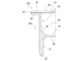
- the high strength portion 92 of the gripper 28G is formed to be thicker than the palm portion 30, and is less likely to be deformed in the thickness direction than the palm portion 30.
- the proximal end 96 of the high strength portion 92 is in contact with the lower surface of the upper case 93.
- the gripper 28G shown in this figure has the high strength portion 92, whereby the same effect as that of the above embodiment can be obtained.
- the palm portion 30 has a substantially disk shape
- the connection portion 38 has a cylindrical shape
- the upper opening of the gripper 28A has a circular shape.
- the palm portion 30, the connection portion 38, and the upper opening may have an oval shape, an oval shape, or a rectangular shape in plan view.
- a plurality of (for example, two) finger portions 32 may be provided along the long side of the palm portion 30, and a total of two sets may be provided on both sides across the palm portion 30.
- a gripping device provided with such a gripper can easily grip long members such as cylindrical and prismatic shapes.
- the example of the orthogonal robot was shown as the industrial robot 12 in the said embodiment, this invention can be applied not only to this but to a SCARA robot, a vertical articulated robot, etc. FIG. That is, even when the industrial robot 12 rotates around the X axis, the Y axis, and the Z axis, the gripping device 10 can grip the workpiece W and maintain the gripped state.
- the gripper 28A may be formed of one type of material, or may be formed by laminating films formed of a plurality of different materials. Alternatively, the grippers 28A may be formed of partially different materials. The thickness of the grippers 28A may not be constant, and partially thick or thin portions may be provided.
- the gripping device 10 may have the finger 32 provided with a claw.
- the claw portion may be a plate-like member made of synthetic resin, a conical member, or a sack-like member.
- the gripping device 10 may include a camera for photographing the workpiece W, a weight scale for measuring the weight of the workpiece W held, and a proximity sensor for measuring the distance between the workpiece W and the gripper 28A.
- the gripper 28A is not limited to the external shape shown in FIG.
- the length and the number of the finger portions 32 can be appropriately selected.
Landscapes
- Engineering & Computer Science (AREA)
- Robotics (AREA)
- Mechanical Engineering (AREA)
- Manipulator (AREA)
- Load-Engaging Elements For Cranes (AREA)
Abstract
Description
以下、図面を参照して本発明の実施形態について詳細に説明する。
図1に、本実施形態に係る把持装置10を適用した産業用ロボット12の構成を示す。産業用ロボット12は、直交ロボットであって、レール14と、レール14に沿って移動する移動体16と、移動体16に固定されたエアシリンダー18とを備える。レール14は、図中Y軸方向に移動可能に設けられている。
上記のように構成された把持装置10が設けられた産業用ロボット12の動作及び効果について説明する。産業用ロボット12は、ピストンロッド20がシリンダーチューブ19内に退避し、エアシリンダー18が収縮した状態を原点とする。また把持装置10は、初期状態においてグリッパ28A内の圧力が大気圧である。すなわち三方弁は、真空ポートが遮断され、給排気ポートが大気解放ポートと繋がっている状態である。
本発明は上記実施形態に限定されるものではなく、本発明の趣旨の範囲内で適宜変更することが可能である。
12 産業用ロボット
28A~28G グリッパ
30 掌部
32 指部
36A~36C ケース
42、60、66、69、74、82、92 高強度部
43 先端
44 基端
45、62、63、68、76 接触面
Claims (7)
- 掌部と、
前記掌部の周囲に突出して設けられ、前記掌部を厚さ方向に変形させることにより前記掌部に向かって倒れる複数の指部と、
前記指部が形成された側と反対側の、前記掌部の外縁を囲む位置に形成され、ケースに接続される接続部と、
前記掌部と前記接続部の間に設けられ、前記掌部の外縁から当該掌部の厚さ方向に所定の長さを有し、前記掌部より変形しにくい高強度部と
が一体に形成されているグリッパ。 - 前記高強度部は、基端において前記ケースの一部と接触する請求項1記載のグリッパ。
- 前記高強度部は、基端に前記ケースと接触する接触面を有する請求項1又は2記載のグリッパ。
- 前記高強度部は、前記掌部より厚肉である請求項1又は2記載のグリッパ。
- 前記高強度部は、前記掌部より、機械的強度の高い材料で形成されている請求項1又は2に記載のグリッパ。
- 請求項1~5のいずれか1項に記載のグリッパと、
前記接続部に接続された前記ケースと
を備える把持装置。 - 請求項6記載の把持装置を設けた産業用ロボット。
Priority Applications (4)
| Application Number | Priority Date | Filing Date | Title |
|---|---|---|---|
| EP18880934.7A EP3718713B1 (en) | 2017-11-27 | 2018-11-08 | Gripper, grasping device, and industrial robot |
| CN201880076618.2A CN111405968B (zh) | 2017-11-27 | 2018-11-08 | 夹具、抓取装置及工业用机器人 |
| US16/765,439 US11298833B2 (en) | 2017-11-27 | 2018-11-08 | Gripper, grasping device, and industrial robot |
| KR1020207018245A KR102509292B1 (ko) | 2017-11-27 | 2018-11-08 | 그리퍼, 파지 장치 및 산업용 로봇 |
Applications Claiming Priority (2)
| Application Number | Priority Date | Filing Date | Title |
|---|---|---|---|
| JP2017-227234 | 2017-11-27 | ||
| JP2017227234A JP6784659B2 (ja) | 2017-11-27 | 2017-11-27 | グリッパ、把持装置及び産業用ロボット |
Publications (1)
| Publication Number | Publication Date |
|---|---|
| WO2019102862A1 true WO2019102862A1 (ja) | 2019-05-31 |
Family
ID=66631897
Family Applications (1)
| Application Number | Title | Priority Date | Filing Date |
|---|---|---|---|
| PCT/JP2018/041512 Ceased WO2019102862A1 (ja) | 2017-11-27 | 2018-11-08 | グリッパ、把持装置及び産業用ロボット |
Country Status (7)
| Country | Link |
|---|---|
| US (1) | US11298833B2 (ja) |
| EP (1) | EP3718713B1 (ja) |
| JP (1) | JP6784659B2 (ja) |
| KR (1) | KR102509292B1 (ja) |
| CN (1) | CN111405968B (ja) |
| TW (1) | TWI768151B (ja) |
| WO (1) | WO2019102862A1 (ja) |
Cited By (5)
| Publication number | Priority date | Publication date | Assignee | Title |
|---|---|---|---|---|
| CN110960090A (zh) * | 2019-12-31 | 2020-04-07 | 北京猎户星空科技有限公司 | 冲泡装置及智能餐饮制备系统 |
| US20220024058A1 (en) * | 2020-07-22 | 2022-01-27 | Berkshire Grey, Inc. | Systems and methods for object processing using a vacuum gripper that provides object retention by shroud inversion |
| US20220024056A1 (en) * | 2020-07-22 | 2022-01-27 | Berkshire Grey, Inc. | Systems and methods for object processing using a passively folding vacuum gripper |
| US12151364B2 (en) | 2016-01-08 | 2024-11-26 | Berkshire Grey Operating Company, Inc. | Systems and methods for acquiring and moving objects |
| US12427671B2 (en) | 2015-08-26 | 2025-09-30 | Berkshire Grey Operating Company, Inc. | Systems and methods for providing contact detection in an articulated arm |
Families Citing this family (7)
| Publication number | Priority date | Publication date | Assignee | Title |
|---|---|---|---|---|
| JP6784659B2 (ja) * | 2017-11-27 | 2020-11-11 | ニッタ株式会社 | グリッパ、把持装置及び産業用ロボット |
| JP7513563B2 (ja) * | 2021-04-12 | 2024-07-09 | ニッタ株式会社 | 把持装置及び産業用ロボット |
| KR102535215B1 (ko) * | 2021-10-08 | 2023-05-26 | 한국기계연구원 | 측면 파지가 가능한 그리퍼 |
| US20240066721A1 (en) * | 2022-08-29 | 2024-02-29 | Hong Kong Centre For Logistics Robotics Limited | Robotic end effectors and soft grippers thereof |
| US20260115938A1 (en) * | 2022-10-11 | 2026-04-30 | The Trustees Of The University Of Pennsylvania | Mechanical metacaps for fast-responsive, tunable and multifunctional soft robots |
| KR102790435B1 (ko) * | 2022-11-10 | 2025-04-04 | 울산과학기술원 | 소프트 그리퍼 |
| CN118901405B (zh) * | 2024-08-12 | 2025-03-04 | 北京市农林科学院智能装备技术研究中心 | 软硬一体折断式果蔬采摘机械手及采摘机器人 |
Citations (6)
| Publication number | Priority date | Publication date | Assignee | Title |
|---|---|---|---|---|
| JPH05503666A (ja) * | 1990-01-26 | 1993-06-17 | クローンセーダー ヘルマン | びん又は類似物のための掴みベル |
| DE4240814A1 (de) * | 1992-12-04 | 1994-06-09 | Bosch Gmbh Robert | Druckmittelbetätigte Greifvorrichtung |
| US5458388A (en) * | 1994-08-03 | 1995-10-17 | Universal Instruments Incorporated | Replaceable nozzle tip with vacuum actuated mechanical gripping fingers |
| JP2011115930A (ja) * | 2009-10-26 | 2011-06-16 | Yaskawa Electric Corp | ロボット装置及びワーク取り出しシステム並びにワーク取り出し方法 |
| JP2013240853A (ja) * | 2012-05-18 | 2013-12-05 | Keylex Corp | ハンド装置 |
| JP2017185553A (ja) | 2016-04-01 | 2017-10-12 | ニッタ株式会社 | 把持装置及び産業用ロボット |
Family Cites Families (23)
| Publication number | Priority date | Publication date | Assignee | Title |
|---|---|---|---|---|
| US4699414A (en) * | 1986-04-21 | 1987-10-13 | The United States Of America As Represented By The Secretary Of The Air Force | Multi use gripper for industrial robot |
| IT1211462B (it) * | 1986-04-21 | 1989-11-03 | Silvestrini Jesus Antonio E Ba | Testa snocciolatrice di frutti quali pesche |
| US4671553A (en) * | 1986-05-15 | 1987-06-09 | Millo Bertini | Gripper device |
| DE9002618U1 (de) | 1990-01-26 | 1990-05-10 | Kronseder, Hermann, 8404 Wörth | Greiftulpe für Flaschen od.dgl. |
| ATE134554T1 (de) * | 1991-09-16 | 1996-03-15 | Sig Schweiz Industrieges | Greifer für einen manipulator |
| DE4432253A1 (de) * | 1994-09-10 | 1996-03-14 | Gerhard Prof Dr Ing Boegelsack | Mechanismus zur Bewegungs- und Kraftübertragung |
| TW566423U (en) | 2003-04-23 | 2003-12-11 | Ind Tech Res Inst | Structure for miniature gripping clip |
| JP2009255191A (ja) | 2008-04-14 | 2009-11-05 | Canon Inc | ロボットマニピュレータ |
| JP2009279707A (ja) | 2008-05-22 | 2009-12-03 | Opto Device Corporation Co Ltd | 把持装置及び搬送装置 |
| DE102009015975B4 (de) * | 2009-03-26 | 2012-01-05 | Festo Ag & Co. Kg | Fluidtechnisches Gerät, insbesondere Greifervorrichtung |
| KR100928674B1 (ko) * | 2009-04-07 | 2009-11-27 | 삼성코닝정밀유리 주식회사 | 비접촉 석션 그립핑 장치 및 이를 갖는 비접촉 석션 그립핑 프레임 |
| DE102010038931B4 (de) * | 2010-08-04 | 2013-11-28 | Deutsches Institut Für Lebensmitteltechnik E.V. | Sauggreifer für Lebensmittel |
| CN102092046B (zh) * | 2010-12-09 | 2013-08-28 | 江南大学 | 带阻尼的气动式单绳牵引多关节的柔性机械手 |
| DE102012001326A1 (de) | 2012-01-25 | 2013-07-25 | Weber Maschinenbau Gmbh Breidenbach | Vorrichtung zum Aufnehmen eines Produktes |
| DE102012100916A1 (de) | 2012-02-03 | 2013-08-08 | Asm Assembly Systems Gmbh & Co. Kg | Greifervorrichtung zum Greifen von Objekten sowie Bestückautomat |
| BE1022062B1 (nl) * | 2013-02-27 | 2016-02-15 | Materialise Nv | Grijpinrichting en systemen en werkwijzen voor de productie van grijpinrichtingen |
| CN203665546U (zh) * | 2014-01-18 | 2014-06-25 | 黑龙江工程学院 | 基于小颗粒物真空状态转换的被动式通用机器手 |
| JP6678648B2 (ja) | 2014-09-26 | 2020-04-08 | テラダイン、 インコーポレイテッド | グリッパと自動試験装置 |
| CN104772768B (zh) * | 2015-02-11 | 2017-03-01 | 江南大学 | 一种仿生柔性腕手 |
| KR20180104667A (ko) | 2016-01-19 | 2018-09-21 | 프레지던트 앤드 펠로우즈 오브 하바드 칼리지 | 소프트 로봇 액추에이터 및 파지기 |
| CN105856185A (zh) * | 2016-05-19 | 2016-08-17 | 清华大学 | 活塞驱动磁流柔性机器人手装置 |
| CN106863333A (zh) * | 2016-11-30 | 2017-06-20 | 合肥瑞硕科技有限公司 | 一种柔性气动机械抓手 |
| JP6784659B2 (ja) | 2017-11-27 | 2020-11-11 | ニッタ株式会社 | グリッパ、把持装置及び産業用ロボット |
-
2017
- 2017-11-27 JP JP2017227234A patent/JP6784659B2/ja active Active
-
2018
- 2018-11-08 KR KR1020207018245A patent/KR102509292B1/ko active Active
- 2018-11-08 WO PCT/JP2018/041512 patent/WO2019102862A1/ja not_active Ceased
- 2018-11-08 CN CN201880076618.2A patent/CN111405968B/zh active Active
- 2018-11-08 EP EP18880934.7A patent/EP3718713B1/en active Active
- 2018-11-08 US US16/765,439 patent/US11298833B2/en active Active
- 2018-11-13 TW TW107140168A patent/TWI768151B/zh active
Patent Citations (6)
| Publication number | Priority date | Publication date | Assignee | Title |
|---|---|---|---|---|
| JPH05503666A (ja) * | 1990-01-26 | 1993-06-17 | クローンセーダー ヘルマン | びん又は類似物のための掴みベル |
| DE4240814A1 (de) * | 1992-12-04 | 1994-06-09 | Bosch Gmbh Robert | Druckmittelbetätigte Greifvorrichtung |
| US5458388A (en) * | 1994-08-03 | 1995-10-17 | Universal Instruments Incorporated | Replaceable nozzle tip with vacuum actuated mechanical gripping fingers |
| JP2011115930A (ja) * | 2009-10-26 | 2011-06-16 | Yaskawa Electric Corp | ロボット装置及びワーク取り出しシステム並びにワーク取り出し方法 |
| JP2013240853A (ja) * | 2012-05-18 | 2013-12-05 | Keylex Corp | ハンド装置 |
| JP2017185553A (ja) | 2016-04-01 | 2017-10-12 | ニッタ株式会社 | 把持装置及び産業用ロボット |
Non-Patent Citations (1)
| Title |
|---|
| See also references of EP3718713A4 |
Cited By (13)
| Publication number | Priority date | Publication date | Assignee | Title |
|---|---|---|---|---|
| US12427671B2 (en) | 2015-08-26 | 2025-09-30 | Berkshire Grey Operating Company, Inc. | Systems and methods for providing contact detection in an articulated arm |
| US12151364B2 (en) | 2016-01-08 | 2024-11-26 | Berkshire Grey Operating Company, Inc. | Systems and methods for acquiring and moving objects |
| CN110960090A (zh) * | 2019-12-31 | 2020-04-07 | 北京猎户星空科技有限公司 | 冲泡装置及智能餐饮制备系统 |
| US11964386B2 (en) * | 2020-07-22 | 2024-04-23 | Berkshire Grey Operating Company, Inc. | Systems and methods for object processing using a vacuum gripper that provides object retention by shroud inversion |
| US11938618B2 (en) * | 2020-07-22 | 2024-03-26 | Berkshire Grey Operating Company, Inc. | Systems and methods for object processing using a passively folding vacuum gripper |
| US11945103B2 (en) * | 2020-07-22 | 2024-04-02 | Berkshire Grey Operating Company, Inc. | Systems and methods for object processing using a passively collapsing vacuum gripper |
| US20220024057A1 (en) * | 2020-07-22 | 2022-01-27 | Berkshire Grey, Inc. | Systems and methods for object processing using a passively collapsing vacuum gripper |
| US12070851B2 (en) | 2020-07-22 | 2024-08-27 | Berkshire Grey Operating Company, Inc. | Systems and methods for object processing using a vacuum gripper that provides object retention by evacuation |
| US20220024056A1 (en) * | 2020-07-22 | 2022-01-27 | Berkshire Grey, Inc. | Systems and methods for object processing using a passively folding vacuum gripper |
| US12257696B2 (en) | 2020-07-22 | 2025-03-25 | Berkshire Grey Operating Company, Inc. | Systems and methods for object processing using a passively collapsing vacuum gripper |
| US12263579B2 (en) | 2020-07-22 | 2025-04-01 | Berkshire Grey Operating Company, Inc. | Systems and methods for object processing using a passively folding vacuum gripper |
| US12296463B2 (en) | 2020-07-22 | 2025-05-13 | Berkshire Grey Operating Company, Inc. | Systems and methods for object processing using a vacuum gripper that provides object retention by shroud inversion |
| US20220024058A1 (en) * | 2020-07-22 | 2022-01-27 | Berkshire Grey, Inc. | Systems and methods for object processing using a vacuum gripper that provides object retention by shroud inversion |
Also Published As
| Publication number | Publication date |
|---|---|
| JP6784659B2 (ja) | 2020-11-11 |
| EP3718713B1 (en) | 2026-01-07 |
| KR102509292B1 (ko) | 2023-03-14 |
| US11298833B2 (en) | 2022-04-12 |
| EP3718713A4 (en) | 2021-09-29 |
| TW201924883A (zh) | 2019-07-01 |
| EP3718713A1 (en) | 2020-10-07 |
| KR20200089733A (ko) | 2020-07-27 |
| CN111405968A (zh) | 2020-07-10 |
| JP2019093530A (ja) | 2019-06-20 |
| US20200324420A1 (en) | 2020-10-15 |
| TWI768151B (zh) | 2022-06-21 |
| CN111405968B (zh) | 2023-03-28 |
Similar Documents
| Publication | Publication Date | Title |
|---|---|---|
| WO2019102862A1 (ja) | グリッパ、把持装置及び産業用ロボット | |
| EP3527337B1 (en) | Gripping device and industrial robot | |
| JP7096832B2 (ja) | 把持装置及び産業用ロボット | |
| WO2019167652A1 (ja) | 把持装置及び産業用ロボット | |
| WO2019167654A1 (ja) | 把持装置及び産業用ロボット | |
| JP7049429B2 (ja) | グリッパ、把持装置及び産業用ロボット | |
| JP6353152B2 (ja) | 把持装置及び産業用ロボット | |
| JP7081973B2 (ja) | 把持装置及び産業用ロボット | |
| JP6456462B2 (ja) | 把持装置及び産業用ロボット |
Legal Events
| Date | Code | Title | Description |
|---|---|---|---|
| 121 | Ep: the epo has been informed by wipo that ep was designated in this application |
Ref document number: 18880934 Country of ref document: EP Kind code of ref document: A1 |
|
| NENP | Non-entry into the national phase |
Ref country code: DE |
|
| ENP | Entry into the national phase |
Ref document number: 20207018245 Country of ref document: KR Kind code of ref document: A |
|
| ENP | Entry into the national phase |
Ref document number: 2018880934 Country of ref document: EP Effective date: 20200629 |
|
| WWG | Wipo information: grant in national office |
Ref document number: 2018880934 Country of ref document: EP |