WO2019103159A1 - 電動アクチュエータ - Google Patents
電動アクチュエータ Download PDFInfo
- Publication number
- WO2019103159A1 WO2019103159A1 PCT/JP2018/043610 JP2018043610W WO2019103159A1 WO 2019103159 A1 WO2019103159 A1 WO 2019103159A1 JP 2018043610 W JP2018043610 W JP 2018043610W WO 2019103159 A1 WO2019103159 A1 WO 2019103159A1
- Authority
- WO
- WIPO (PCT)
- Prior art keywords
- electric motor
- housing
- relay circuit
- electric actuator
- conversion mechanism
- Prior art date
- Legal status (The legal status is an assumption and is not a legal conclusion. Google has not performed a legal analysis and makes no representation as to the accuracy of the status listed.)
- Ceased
Links
Images

Classifications
-
- H—ELECTRICITY
- H02—GENERATION; CONVERSION OR DISTRIBUTION OF ELECTRIC POWER
- H02K—DYNAMO-ELECTRIC MACHINES
- H02K5/00—Casings; Enclosures; Supports
-
- H—ELECTRICITY
- H02—GENERATION; CONVERSION OR DISTRIBUTION OF ELECTRIC POWER
- H02K—DYNAMO-ELECTRIC MACHINES
- H02K7/00—Arrangements for handling mechanical energy structurally associated with dynamo-electric machines, e.g. structural association with mechanical driving motors or auxiliary dynamo-electric machines
- H02K7/06—Means for converting reciprocating motion into rotary motion or vice versa
-
- H—ELECTRICITY
- H02—GENERATION; CONVERSION OR DISTRIBUTION OF ELECTRIC POWER
- H02K—DYNAMO-ELECTRIC MACHINES
- H02K7/00—Arrangements for handling mechanical energy structurally associated with dynamo-electric machines, e.g. structural association with mechanical driving motors or auxiliary dynamo-electric machines
- H02K7/10—Structural association with clutches, brakes, gears, pulleys or mechanical starters
- H02K7/116—Structural association with clutches, brakes, gears, pulleys or mechanical starters with gears
-
- F—MECHANICAL ENGINEERING; LIGHTING; HEATING; WEAPONS; BLASTING
- F16—ENGINEERING ELEMENTS AND UNITS; GENERAL MEASURES FOR PRODUCING AND MAINTAINING EFFECTIVE FUNCTIONING OF MACHINES OR INSTALLATIONS; THERMAL INSULATION IN GENERAL
- F16H—GEARING
- F16H25/00—Gearings comprising primarily only cams, cam-followers and screw-and-nut mechanisms
- F16H25/18—Gearings comprising primarily only cams, cam-followers and screw-and-nut mechanisms for conveying or interconverting oscillating or reciprocating motions
- F16H25/20—Screw mechanisms
Definitions
- the present invention relates to an electric actuator.
- Patent Document 1 discloses a so-called mechanical-electric integrated electric actuator in which a drive component such as an electric motor and an electronic component for controlling the drive component are integrally assembled.
- a drive component such as an electric motor and an electronic component for controlling the drive component
- a box-like case is provided in a housing to which an electric motor or the like is attached, and an electronic component for controlling driving of the electric motor is accommodated in the case.
- the drive component and the electronic component are integrally assembled.
- an object of this invention is to provide the electrically-driven actuator which can reduce a sealing location and can achieve cost reduction.
- the present invention relates to an electric motor, a relay circuit for switching ON / OFF of power supply to the electric motor, and a movement for converting the rotational movement of the electric motor into movement in different directions and outputting it.
- an electric actuator including a conversion mechanism and a housing
- the housing is formed by joining two housing divided bodies to one another, and in an internal space formed by joining two housing divided bodies, an electric motor, a relay circuit, A motion conversion mechanism is housed.
- the electric motor and the motion conversion mechanism which are drive parts, and the relay circuit as the electronic part are accommodated in an internal space formed by joining two housing divided bodies.
- the drive component and the electronic component are disposed in separate spaces.
- the number of seal structures, operations, and inspections necessary for securing the sealing performance can be reduced, so that the cost of the electric actuator can be reduced.
- the reliability regarding dust resistance or waterproofness is also improved.
- the electric actuator according to the present invention includes a reduction gear for transmitting the rotation from the electric motor to the motion conversion mechanism at a reduced speed
- the electric motor and the relay circuit are formed in the internal space formed by joining two housing divisions.
- a speed reducer may be accommodated.
- all the other components may be accommodated in an internal space formed by joining the two housing segments.
- dustproofness or waterproofness of all the components can be secured only by sealing the two housing divided bodies, so that the cost required for sealing can be more effectively reduced, and dustproofness or dustproofness can be achieved.
- the reliability regarding waterproofness is further improved.
- the relay circuit may be a contact type relay circuit or a non-contact type relay circuit.
- a seal structure may be provided between the joint surfaces of the housing divided bodies.
- the joint surfaces of the housing divisions be formed in the same plane. By forming the joint surfaces in the same plane, even if a slight displacement occurs between the joint surfaces of the housing divisions during assembly, a gap is not easily generated between the joint surfaces, so sealing performance is ensured. It will be easier.
- the present invention is applicable to, for example, an electric actuator in which the output unit of the motion conversion mechanism rotates in the forward or reverse direction in a direction different from the rotational movement of the electric motor.
- FIG. 1 It is a perspective view which shows the internal structure of the electrically-driven actuator which concerns on one Embodiment of this invention. It is a front view which shows the internal structure of the electrically-driven actuator shown in FIG. It is a figure which shows the structure of a reduction gear. It is a block diagram which shows the electric constitution of the electrically-driven actuator shown in FIG. It is a front view which shows the internal structure of the electrically-driven actuator which concerns on other embodiment of this invention.
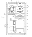
- FIG. 1 is a perspective view showing the internal structure of an electric actuator according to an embodiment of the present invention
- FIG. 2 is a front view showing the internal structure of the electric actuator shown in FIG.
- the electric actuator 100 includes an electric motor 2, a relay circuit 3 for switching ON / OFF of power supply to the electric motor 2, and rotational motion of the electric motor 2.
- Main components are a motion conversion mechanism 4 that converts and outputs motion in a direction different from that, a reduction gear 5 that transmits rotation from the electric motor 2 to the motion conversion mechanism 4 at a reduced speed, and a housing 1 that houses all of them.
- the motion conversion mechanism 4 includes a linear motion conversion mechanism 8 that converts rotational motion into linear motion, a swing member 6 that converts linear motion into rotational motion, and an output unit 7.
- a sliding screw mechanism is used as the linear motion conversion mechanism 8.
- the slide screw mechanism is configured of a screw shaft 9 having a screw groove formed on the outer peripheral surface, and a cylindrical nut 10 having a screw groove screwed with the screw shaft 9 on the inner peripheral surface. Both ends of the screw shaft 9 are rotatably supported by the housing 1.
- a ball screw mechanism may be used instead of the slide screw mechanism.
- the swing member 6 is connected to the nut 10 of the slide screw mechanism. Specifically, the nut 10 is inserted into the rectangular frame portion 6a of the swinging member 6, and the pin-like connecting member 11 is attached to the nut 10 through the long hole 6b provided in the frame portion 6a. It is done. Thus, the swinging member 6 is swingably connected to the nut 10 with the connecting member 11 as an axis.
- the swinging member 6 also has a pair of arms 6c that are bifurcated.
- the cylindrical output unit 7 is held by the arms 6 c.
- the reduction gear 5 is connected to the electric motor 2 and the motion conversion mechanism 4.
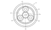
- a planetary gear reducer as shown in FIG. 3 is used as the reducer 5.
- the reduction gear 5 rotates between the sun gear 12 as an input rotating body, a ring gear 13 as a track ring disposed on the outer periphery of the sun gear 12, the sun gear 12 and the ring gear 13.
- a plurality of planet gears 14 as planet rotors, which are arranged as possible, and a carrier 15 as an output rotor that holds each planet gear 14 are provided.
- the sun gear 12 is fixed to the rotation shaft 2 a of the electric motor 2 and rotates integrally with the rotation shaft 2 a of the electric motor 2.
- the ring gear 13 is fixed so as not to rotate with respect to the housing 1.
- the plurality of planet gears 14 are disposed between the sun gear 12 and the ring gear 13 and assembled so as to mesh with these.
- Each planetary gear 14 is rotatably attached to the carrier 15 by a pin or the like.
- the carrier 15 is fixed to one end of the screw shaft 9 of the motion conversion mechanism 4 (see FIG. 1), and is configured to rotate integrally with the screw shaft 9.
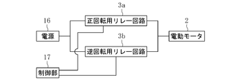
- the relay circuit 3 is a relay circuit having a contact type, and a forward rotation relay circuit 3a for causing a current in the forward direction to flow in the electric motor 2 for forward rotation, and a current in the reverse direction for the electric motor 2 It is configured with a reverse rotation relay circuit 3b for reverse rotation.
- each of the relay circuits 3a and 3b is connected between the power supply 16 and the electric motor 2, and the power supply to the electric motor 2 is turned on by a signal from the control unit 17 comprising a CPU or the like. It has a contact that switches on / off. Further, in the present embodiment, a DC motor with a brush is used as the electric motor 2. When the contacts of each of the relay circuits 3a and 3b are both off, no power is supplied from the power supply 16 to the electric motor 2, and the electric motor 2 is in a stopped state.
- each housing divided body 1a, 1b includes a first housing portion 18 in which the electric motor 2 and the relay circuit 3 are housed, a second housing portion 19 in which the motion conversion mechanism 4 is housed, and the reduction gear 5 A third accommodating portion 20 which is accommodated is formed. Moreover, the partition part 21 which partitions off these accommodating parts 18, 19, and 20 is provided in each housing division body 1a, 1b.
- the three space portions (the first accommodation portion separated from each other by the partition portion 21 between the two housing divisions 1a and 1b) 18, the second accommodating portion 19 and the third accommodating portion 20) are formed.
- the hatched portions in FIG. 2 are joint surfaces which contact each other when the two housing divided bodies 1a and 1b are joined to each other.
- the joint surface of one housing division body 1a is shown in FIG. 2, the joint surface of the other housing division body 1b is formed similarly.
- the joint surface is formed by the outer peripheral edge portion 22 of each of the housing divisions 1 a and 1 b and the partition portion 21.
- a seal groove 23 for mounting or applying a seal material (not shown) is provided over the entire circumference of the outer peripheral edge portion 22 (joining surface) of one housing divided body 1a.
- the sealing material may be a solid sealing material such as an O-ring, a rubber sheet, a resin sheet, a joint sheet, a metal gasket, or a liquid sealing material such as a liquid gasket.
- the respective components of the electric motor 2, the relay circuit 3, the motion conversion mechanism 4 and the reduction gear 5 are housed in the respective housing portions 18, 19, 20 of one housing divided body 1a, and the seal material is
- the sealing material seals the joint surfaces. This prevents the entry of foreign matter such as dust and water into the housing 1.
- a through hole 24 for inserting the above-mentioned spline shaft (operation shaft) provided in the used device and connecting it to the output unit 7 is formed in the housing division 1 b shown on the front side.
- the gap between the through hole 24 and the spline shaft (operation shaft) is sealed by another seal material.
- the electric actuator As described above, in the present embodiment, all components (other than the housing) of the electric actuator are configured to be accommodated in the housing 1 divided into two, so only the outer peripheral edge portion of the housing 1
- the seal structure in the present embodiment, the seal groove and the seal material
- the relay circuit 3 which is an electronic component is housed together with the respective drive components of the electric motor 2, the motion conversion mechanism 4 and the reduction gear 5 in an internal space formed by joining the two housing divisions 1a and 1b. Therefore, compared with the configuration described in Patent Document 1 in which the electronic component and the drive component are disposed in separate spaces, the number of places that need to ensure the sealing property is reduced, so the sealing property is necessary. Seal structure, work, and the number of inspections can be reduced.
- the joint surfaces of the housing divisions 1a and 1b are formed in the same plane without steps, a slight deviation occurs between the joint surfaces of the housing divisions during assembly. Also, a gap does not easily occur between the joint surfaces, and sealing performance is easily ensured. In addition, as long as sealing property can be ensured, the case where there is a step on the bonding surface may be used.
- the housing (the first housing 18) in which the electric motor 2 and the relay circuit 3 are housed, and the other housing (the second housing in which the motion conversion mechanism 4 or the reduction gear 5 is housed)
- the partitioning portion 21 By separating the space between the first housing portion 19 and the third housing portion 20) by the partitioning portion 21, foreign matter such as wear powder and grease from the motion conversion mechanism 4 and the reduction gear 5 is prevented from adhering to the relay circuit 3. it can. This makes it possible to avoid the possibility of malfunction or failure due to the adhesion of foreign matter to the relay circuit 3.
- the electric actuator 100 includes, as the relay circuit 3, a noncontact relay circuit 3 using a MOS-FET or the like.
- the noncontact relay circuit 3 since the switching operation can be electrically performed using a semiconductor element, there is an advantage that the durability is superior to that of a contact relay circuit in which the switching operation is mechanically performed. is there.
- the contact type relay circuit is inexpensive, the cost of the electric actuator can be reduced.
- the motion conversion mechanism 4 is configured by a worm gear mechanism having a worm (screw gear) 30 and a cam gear 31 meshing with the worm gear 30 instead of the slide screw mechanism. It is done.
- the cam gear 31 is integrally formed with the swinging member 6, and when the worm 30 is rotated forward or reverse by the drive of the electric motor 2, the swinging member 6 is in the C1 direction or C2 in FIG. Swing in the direction.
- the output unit 7 rotationally moves in the forward direction or the reverse direction within the predetermined angle range around its axis.
- the relay circuit 3 is not limited to the contact type but may be a non-contact type.
- the combination of the type of relay circuit 3 used for the electric actuator and the type of motion conversion mechanism 4 can be changed as appropriate.
- the electric actuator according to the present invention may be provided with a noncontact relay circuit 3 and a sliding screw motion conversion mechanism 4 in addition to the combinations mentioned in the above-described embodiments, A contact type relay circuit 3 and a motion conversion mechanism 4 of a worm gear may be provided.
- the seal groove 23 is provided in one of the pair of housing divisions, but the seal groove may not be provided in any of the housing divisions.
- the sealing property can be secured by mounting a sheet-like sealing material or applying a liquid sealing material between the pair of housing divided bodies.
- the reduction gear is not limited to the planetary gear reduction gear, and may be, for example, a cycloid reduction gear. In addition, it is possible to omit the reduction gear if it is not necessary and to provide a reduction gear.
- Reference Signs List 1 housing 1a housing division 1b housing division 2 electric motor 3 relay circuit 4 motion conversion mechanism 5 reduction gear 6 rocking member 7 output section 21 partition section 23 seal groove 100 electric actuator
Landscapes
- Engineering & Computer Science (AREA)
- Power Engineering (AREA)
- Connection Of Motors, Electrical Generators, Mechanical Devices, And The Like (AREA)
Abstract
電動モータ2と、電動モータ2への電力供給のON/OFFを切り換えるリレー回路3と、電動モータ2の回転運動をそれとは異なる方向の運動に変換して出力する運動変換機構4と、ハウジング1とを備える電動アクチュエータにおいて、ハウジング1は、2つのハウジング分割体1a,1bを互いに接合して構成され、2つのハウジング分割体1a,1bが接合されて形成された内部空間に、電動モータ2、リレー回路3、運動変換機構4を収容した。
Description
本発明は、電動アクチュエータに関する。
近年、車両等の省力化、低燃費化のために電動化が進み、例えば、自動車の自動変速機やブレーキ、ステアリング等の操作を電動機の力で行うシステムが開発され、市場に投入されている。
このような用途に使用される電動アクチュエータとして、例えば特許文献1には、電動モータ等の駆動部品と、駆動部品を制御する電子部品とが一体的に組み付けられた、いわゆる機電一体型の電動アクチュエータが提案されている。具体的に、特許文献1に記載の構成では、電動モータ等が組み付けられるハウジングに箱状のケースが設けられており、このケース内に電動モータの駆動を制御するための電子部品が収容されることで、駆動部品と電子部品とが一体的に組み付けられている。
しかしながら、特許文献1に記載の構成においては、電子部品が駆動部品とは別の空間内に収容されているため、駆動部品と電子部品との両方に対して防塵又は防水対策をしようとすると、それぞれが配置される空間を個別に密閉処理する必要がある。このように、電子部品を駆動部品とは別の空間内に収容すると、密閉箇所が増えるため、密閉に必要なシール材の数の増加や、組み立て作業の複雑化、さらには密閉性の検査箇所の増加に繋がり、電動アクチュエータが高コスト化するといった課題がある。
そこで、本発明は、密閉箇所を削減し、低コスト化を図れる電動アクチュエータを提供することを目的とする。
上記課題を解決するため、本発明は、電動モータと、電動モータへの電力供給のON/OFFを切り換えるリレー回路と、電動モータの回転運動をそれとは異なる方向の運動に変換して出力する運動変換機構と、ハウジングとを備える電動アクチュエータにおいて、ハウジングは、2つのハウジング分割体を互いに接合して構成され、2つのハウジング分割体が接合されて形成された内部空間に、電動モータ、リレー回路、運動変換機構を収容したことを特徴とする。
このように、本発明に係る電動アクチュエータにおいては、2つのハウジング分割体が接合されて形成された内部空間に、駆動部品である電動モータ及び運動変換機構と、電子部品としてのリレー回路とが収容されていることで、駆動部品と電子部品とを別個の空間内に配置する構成に比べて、密閉性を確保する必要のある箇所を減らすことができる。これにより、密閉性確保のために必要なシール構造や作業、検査の数を減らすことができるので、電動アクチュエータの低コスト化を図ることが可能である。また、密閉箇所が減ることで、内部への異物侵入の可能性も低減するので、防塵性又は防水性に関する信頼性も向上する。
また、本発明に係る電動アクチュエータが、電動モータから運動変換機構へ回転を減速して伝える減速機を備える場合、2つのハウジング分割体が接合されて形成された内部空間に、電動モータ、リレー回路、運動変換機構に加えて、減速機を収容してもよい。
特に、望ましくは、2つのハウジング分割体が接合されて形成された内部空間に、他の(ハウジング分割体以外の)全ての構成部品が収容されるように構成されているとよい。この場合、2つのハウジング分割体を密閉するだけで、全ての構成部品についての防塵性又は防水性を確保することができるので、密閉に必要なコストをより効果的に低減できると共に、防塵性又は防水性に関する信頼性が一層向上する。
また、電動モータとリレー回路とが収容された空間と、運動変換機構が収容された空間との間に、仕切部を設けることで、運動変換機構からの摩耗粉やグリース等の異物がリレー回路に付着するのを防止できる。これにより、リレー回路に異物が付することによる誤作動や故障等の虞を回避できるようになる。
リレー回路は、有接点式のリレー回路であってもよいし、無接点式のリレー回路であってもよい。
また、接合面間の密閉性を向上させるため、ハウジング分割体同士の接合面間にシール構造を設けてもよい。
ハウジング分割体同士の接合面は、同一平面状に形成されるのが好ましい。接合面を同一平面状に形成することで、組み付け時に、ハウジング分割体の接合面同士の間で多少のずれが生じても、接合面同士の間に隙間が生じにくいため、密閉性を確保しやすくなる。
また、本発明は、例えば、運動変換機構の出力部が、電動モータの回転運動とは異なる方向で正方向又は逆方向に回転運動する電動アクチュエータに適用可能である。
本発明によれば、密閉箇所を削減し、低コスト化を図れる電動アクチュエータを提供することができる。
以下、添付の図面に基づき、本発明について説明する。なお、本発明を説明するための各図面において、同一の機能もしくは形状を有する部材や構成部品等の構成要素については、判別が可能な限り同一符号を付すことにより一度説明した後ではその説明を省略する。
図1は、本発明の実施の一形態に係る電動アクチュエータの内部構造を示す斜視図、図2は、図1に示す電動アクチュエータの内部構造を示す正面図である。
図1及び図2に示すように、本実施形態に係る電動アクチュエータ100は、電動モータ2と、電動モータ2への電力供給のON/OFFを切り換えるリレー回路3と、電動モータ2の回転運動をそれとは異なる方向の運動に変換して出力する運動変換機構4と、電動モータ2から運動変換機構4へ回転を減速して伝える減速機5と、これら全てを収容するハウジング1とを主要な構成としている。
運動変換機構4は、回転運動を直線運動に変換する直動変換機構8と、直線運動を回転運動に変換する揺動部材6と、出力部7とで構成されている。本実施形態では、直動変換機構8として、すべりねじ機構を用いている。すべりねじ機構は、外周面にねじ溝が形成されたねじ軸9と、ねじ軸9に対して螺合するねじ溝を内周面に有する円筒状のナット10とで構成されている。ねじ軸9の両端部は、ハウジング1によって回転可能に支持されている。なお、すべりねじ機構に代えて、ボールねじ機構を用いてもよい。電動モータ2が正回転又は逆回転して、その回転運動が減速機5を介してねじ軸9に伝達されると、ねじ軸9が正回転又は逆回転し、これに伴ってナット10が軸方向に前進又は後退することで、回転運動が直線運動に変換される。
上記すべりねじ機構のナット10には、揺動部材6が連結されている。具体的には、揺動部材6が有する矩形の枠体部6a内にナット10が挿入されており、ピン状の連結部材11が枠体部6aに設けられた長孔6bを通してナット10に取り付けられている。これにより、揺動部材6は、連結部材11を軸にナット10に対して揺動可能に連結されている。また、揺動部材6は、二股に分かれた一対の腕部6cを有する。これらの腕部6cによって、筒状の出力部7が保持されている。
電動モータ2によってねじ軸9が正回転又は逆回転させられ、ナット10が図2中のA1方向又はA2方向に移動すると、これに連動して揺動部材6が図2中のB1方向又はB2方向に揺動することで、出力部7がその軸心回りに所定角度範囲内で正方向又は逆方向に回転運動する。出力部7の内周面には、軸方向に延びるスプライン7aが形成されている。このスプライン7aが形成された内周面に対して、操作対象である図示しない使用機器に設けられたスプライン軸(操作軸)が連結される。
減速機5は、電動モータ2と運動変換機構4との間でこれらに連結されている。本実施形態では、減速機5として、図3に示すような遊星ギヤ減速機を用いている。
図3に示すように、減速機5は、入力回転体としての太陽ギヤ12と、太陽ギヤ12の外周に配置された軌道リングとしてのリングギヤ13と、太陽ギヤ12とリングギヤ13との間に回転可能に配置された遊星回転体しての複数の遊星ギヤ14と、各遊星ギヤ14を保持する出力回転体としてのキャリア15とを有する。
太陽ギヤ12は、電動モータ2の回転軸2aに対して固定されており、電動モータ2の回転軸2aと一体的に回転する。リングギヤ13は、ハウジング1に対して回転しないように固定されている。複数の遊星ギヤ14は、太陽ギヤ12とリングギヤ13との間に配置され、これらと噛み合うように組み付けられている。また、各遊星ギヤ14は、ピン等によりキャリア15に対して回転可能に取り付けられている。キャリア15は、運動変換機構4のねじ軸9の一端部に固定され(図1参照)、ねじ軸9と一体的に回転するように構成されている。
上記のように構成された減速機5において、電動モータ2が駆動を開始することにより太陽ギヤ12が回転すると、これに伴って複数の遊星ギヤ14が自転しながらリングギヤ13に沿って公転する。これにより、キャリア15が減速されて回転する。そして、減速された回転運動が運動変換機構4のねじ軸9に伝達されると、ねじ軸9、ナット10及び揺動部材6の上述の作用により出力部7が回転する。
リレー回路3は、有接点式のリレー回路であり、電動モータ2に正方向の電流を流して正回転させるための正回転用リレー回路3aと、反対に電動モータ2逆方向の電流を流して逆回転させるための逆回転用リレー回路3bとで構成されている。
図4に示すように、各リレー回路3a,3bは、電源16と電動モータ2との間に接続されており、CPU等から成る制御部17からの信号によって電動モータ2への電力供給のON/OFFを切り換える接点を有する。また、本実施形態では、電動モータ2としてブラシ付きDCモータを用いている。各リレー回路3a,3bの接点が両方ともOFFの状態では、電源16から電動モータ2へ電力は供給されず、電動モータ2が停止状態となっている。この状態から、制御部17の信号によって正回転用リレー回路3aの接点がONの状態に切り換えられると、電源16から電動モータ2へ正方向の電流が流れ電動モータ2が正回転させられる。また、各リレー回路3a,3bの接点が両方ともOFFの状態から、制御部17の信号によって逆回転用リレー回路3bの接点がONの状態に切り換えられると、電源16から電動モータ2へ逆方向の電流が流れ電動モータ2が逆回転させられる。このように、各リレー回路3a,3bの接点が切り換えられることで、電動モータ2が正回転又は逆回転させられ、上述の作用によりすべりねじ機構のナット10が前進又は後退する。
図1に示すように、ハウジング1は、二分割されており、2つのハウジング分割体1a,1bが互いに接合されて構成されている。各ハウジング分割体1a,1bには、電動モータ2とリレー回路3とが収容されている第1収容部18と、運動変換機構4が収容されている第2収容部19と、減速機5が収容されている第3収容部20とが形成されている。また、各ハウジング分割体1a,1bには、これらの収容部18,19,20同士を仕切る仕切部21が設けられている。このように、本実施形態では、2つのハウジング分割体1a,1b同士を接合すると、両ハウジング分割体1a,1bの間に、仕切部21によって互いに仕切られた3つの空間部(第1収容部18、第2収容部19、第3収容部20)が形成される。
図2において斜線で示す部分が、2つのハウジング分割体1a,1b同士を接合した場合に互いに接触する接合面である。なお、図2では、一方のハウジング分割体1aの接合面だけ示しているが、他方のハウジング分割体1bの接合面も同様に形成されている。本実施形態では、接合面が、各ハウジング分割体1a,1bの外周縁部22と仕切部21とによって形成されている。また、一方のハウジング分割体1aの外周縁部22(接合面)には、シール材(図示省略)を装着又は塗布するためのシール溝23が全周に渡って設けられている。
シール材は、Oリング、ゴムシート、樹脂シート、ジョイントシート、メタルガスケット等の固体のシール材又は液状ガスケット等の液体のシール材を採用することができる。
従って、一方のハウジング分割体1aの各収容部18,19,20内に電動モータ2、リレー回路3、運動変換機構4及び減速機5の各構成部品を収容し、シール溝23にシール材を装着又は塗布して、ハウジング分割体1a,1b同士を図示しない固定具を用いて接合すると、シール材によって接合面間が密閉される。これにより、ハウジング1内への粉塵や水等の異物の侵入が防止される。また、図1において、手前側に示すハウジング分割体1bには、使用機器に設けられた上記スプライン軸(操作軸)を挿通させて出力部7に連結するための貫通孔24が形成されているが、この貫通孔24とスプライン軸(操作軸)との隙間は別のシール材によって密閉される。
このように、本実施形態においては、電動アクチュエータの(ハウジング以外の)全ての構成部品が二分割されたハウジング1内に収容されるように構成されているので、ハウジング1の外周縁部のみにシール構造(本実施形態では、シール溝及びシール材)を設けるだけで、構成部品全ての防塵性又は防水性を確保することができる。すなわち、2つのハウジング分割体1a,1bが接合されて形成された内部空間に、電動モータ2、運動変換機構4及び減速機5の各駆動部品と一緒に電子部品であるリレー回路3が収容されているため、電子部品と駆動部品とを別個の空間内に配置する上記特許文献1に記載の構成に比べて、密閉性を確保する必要のある箇所が減るので、密閉性確保のために必要なシール構造や作業、検査の数を減らすことができる。
また、本実施形態では、各ハウジング分割体1a,1bの接合面が段差の無い同一平面状に形成されているので、組み付け時に、ハウジング分割体の接合面同士の間で多少のずれが生じても、接合面同士の間に隙間が生じにくく、密閉性を確保しやすい。なお、密閉性を確保できれば、接合面に段差がある場合であっても構わない。
また、本実施形態では、電動モータ2及びリレー回路3が収容される収容部(第1収容部18)と、運動変換機構4又は減速機5が収容される他の収容部(第2収容部19、第3収容部20)との間が仕切部21によって仕切られていることで、運動変換機構4や減速機5からの摩耗粉やグリース等の異物がリレー回路3に付着するのを防止できる。これにより、リレー回路3に異物が付着することによる誤作動や故障等の虞を回避できるようになる。
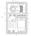
続いて、図5に基づき、本発明の他の実施形態について説明する。主に上述の実施形態とは異なる部分について説明し、それ以外の部分は基本的に同様であるので説明を省略する。
図5に示すように、他の実施形態に係る電動アクチュエータ100は、リレー回路3として、MOS-FET等を用いた無接点式のリレー回路3を備えている。無接点式のリレー回路3の場合、半導体素子を用いて電気的にスイッチング動作を行うことができるので、機械的にスイッチング動作を行う有接点式のリレー回路に比べて、耐久性に優れる利点がある。一方、有接点式のリレー回路は、安価であるので、電動アクチュエータの低コスト化を図ることが可能である。
また、他の実施形態に係る電動アクチュエータ100おいては、運動変換機構4が、上記すべりねじ機構に代えて、ウォーム(ねじ歯車)30と、これと噛み合うカムギヤ31と、を有するウォームギヤ機構で構成されている。本実施形態では、カムギヤ31が、揺動部材6と一体に構成されており、電動モータ2の駆動によりウォーム30が正回転又は逆回転すると、揺動部材6が図5中のC1方向又はC2方向に揺動する。これにより、上述の実施形態と同様に、出力部7がその軸心回りに所定角度範囲内で正方向又は逆方向に回転運動する。
このように、本発明に係る電動アクチュエータにおいては、運動変換機構4として、すべりねじ機構のほかに、ウォームギヤ機構を採用することも可能である。また、リレー回路3は、有接点式のものに限らず、無接点式のものであってもよい。また、電動アクチュエータに用いられるリレー回路3の種類と運動変換機構4の種類との組み合わせは、適宜変更可能である。例えば、上述の各実施形態に挙げられる組み合わせのほか、本発明に係る電動アクチュエータは、無接点式のリレー回路3と、すべりねじの運動変換機構4とを備えるものであってもよいし、有接点式のリレー回路3と、ウォームギヤの運動変換機構4とを備えるものであってもよい。
また、本発明は、その要旨を逸脱しない範囲内において、さらに種々なる形態で実施し得ることは勿論のことである。
上記実施形態では、一対のハウジング分割体の一方にシール溝23が設けられているが、いずれのハウジング分割体にもシール溝を設けない構成とすることもできる。その場合、一対のハウジング分割体の間に、シート状のシール材を装着したり、液状のシール材を塗布したりすることで、密閉性を確保することが可能である。
また、上記実施形態では、電動モータとして、安価なブラシ付きDCモータを用いているが、ブラシレスモータ等の他の電動モータを用いてもよい。また、減速機は、遊星ギヤ減速機に限らず、例えばサイクロイド減速機であってもよい。また、必要なければ減速機を省略し、減速機を設けない構成とすることも可能である。
1 ハウジング
1a ハウジング分割体
1b ハウジング分割体
2 電動モータ
3 リレー回路
4 運動変換機構
5 減速機
6 揺動部材
7 出力部
21 仕切部
23 シール溝
100 電動アクチュエータ
1a ハウジング分割体
1b ハウジング分割体
2 電動モータ
3 リレー回路
4 運動変換機構
5 減速機
6 揺動部材
7 出力部
21 仕切部
23 シール溝
100 電動アクチュエータ
Claims (9)
- 電動モータと、前記電動モータへの電力供給のON/OFFを切り換えるリレー回路と、前記電動モータの回転運動をそれとは異なる方向の運動に変換して出力する運動変換機構と、ハウジングとを備える電動アクチュエータにおいて、
前記ハウジングは、2つのハウジング分割体を互いに接合して構成され、
前記2つのハウジング分割体が接合されて形成された内部空間に、前記電動モータ、前記リレー回路、前記運動変換機構を収容したことを特徴とする電動アクチュエータ。 - 前記電動モータから前記運動変換機構へ回転を減速して伝える減速機を備え、
前記2つのハウジング分割体が接合されて形成された内部空間に、前記電動モータ、前記リレー回路、前記運動変換機構に加えて、前記減速機を収容した請求項1に記載の電動アクチュエータ。 - 前記2つのハウジング分割体が接合されて形成された内部空間に、他の全ての構成部品を収容した請求項1又は2に記載の電動アクチュエータ。
- 前記電動モータと前記リレー回路とが収容された空間と、前記運動変換機構が収容された空間との間に、仕切部を設けた請求項1から3のいずれか1項に記載の電動アクチュエータ。
- 前記リレー回路は、有接点式のリレー回路である請求項1から4のいずれか1項に記載の電動アクチュエータ。
- 前記リレー回路は、無接点式のリレー回路である請求項1から4のいずれか1項に記載の電動アクチュエータ。
- 前記ハウジング分割体同士の接合面間にシール構造を設けた請求項1から6のいずれか1項に記載の電動アクチュエータ。
- 前記ハウジング分割体同士の接合面が、同一平面状に形成されている請求項1から7のいずれか1項に記載の電動アクチュエータ。
- 前記運動変換機構は、前記電動モータの回転運動とは異なる方向で正方向又は逆方向に回転運動する出力部を有する請求項1から8のいずれか1項に記載の電動アクチュエータ。
Priority Applications (2)
| Application Number | Priority Date | Filing Date | Title |
|---|---|---|---|
| US16/762,588 US11476732B2 (en) | 2017-11-27 | 2018-11-27 | Electric actuator |
| EP18880283.9A EP3719965A4 (en) | 2017-11-27 | 2018-11-27 | ELECTRIC ACTUATOR |
Applications Claiming Priority (4)
| Application Number | Priority Date | Filing Date | Title |
|---|---|---|---|
| JP2017226804 | 2017-11-27 | ||
| JP2017-226804 | 2017-11-27 | ||
| JP2018-219284 | 2018-11-22 | ||
| JP2018219284A JP7240150B2 (ja) | 2017-11-27 | 2018-11-22 | 電動アクチュエータ |
Publications (1)
| Publication Number | Publication Date |
|---|---|
| WO2019103159A1 true WO2019103159A1 (ja) | 2019-05-31 |
Family
ID=66631039
Family Applications (1)
| Application Number | Title | Priority Date | Filing Date |
|---|---|---|---|
| PCT/JP2018/043610 Ceased WO2019103159A1 (ja) | 2017-11-27 | 2018-11-27 | 電動アクチュエータ |
Country Status (1)
| Country | Link |
|---|---|
| WO (1) | WO2019103159A1 (ja) |
Citations (5)
| Publication number | Priority date | Publication date | Assignee | Title |
|---|---|---|---|---|
| JP2000039051A (ja) * | 1998-07-22 | 2000-02-08 | Tokico Ltd | リニア型アクチュエータ |
| JP2008304062A (ja) * | 2007-06-11 | 2008-12-18 | Warn Ind Inc | 4輪駆動中央断続電気アクチュエータ |
| JP2011114921A (ja) * | 2009-11-26 | 2011-06-09 | Ntn Corp | 電動アクチュエータ |
| JP2013219949A (ja) * | 2012-04-10 | 2013-10-24 | Mitsuba Corp | 燃料遮断弁用のアクチュエータ |
| JP2015058820A (ja) | 2013-09-19 | 2015-03-30 | 日立オートモティブシステムズ株式会社 | ブレーキ制御装置 |
-
2018
- 2018-11-27 WO PCT/JP2018/043610 patent/WO2019103159A1/ja not_active Ceased
Patent Citations (5)
| Publication number | Priority date | Publication date | Assignee | Title |
|---|---|---|---|---|
| JP2000039051A (ja) * | 1998-07-22 | 2000-02-08 | Tokico Ltd | リニア型アクチュエータ |
| JP2008304062A (ja) * | 2007-06-11 | 2008-12-18 | Warn Ind Inc | 4輪駆動中央断続電気アクチュエータ |
| JP2011114921A (ja) * | 2009-11-26 | 2011-06-09 | Ntn Corp | 電動アクチュエータ |
| JP2013219949A (ja) * | 2012-04-10 | 2013-10-24 | Mitsuba Corp | 燃料遮断弁用のアクチュエータ |
| JP2015058820A (ja) | 2013-09-19 | 2015-03-30 | 日立オートモティブシステムズ株式会社 | ブレーキ制御装置 |
Non-Patent Citations (1)
| Title |
|---|
| See also references of EP3719965A4 |
Similar Documents
| Publication | Publication Date | Title |
|---|---|---|
| JP7240150B2 (ja) | 電動アクチュエータ | |
| CN109923767B (zh) | 电动致动器 | |
| WO2016010021A1 (ja) | ブラシレスワイパモータ | |
| KR20120080528A (ko) | 모터 장치 | |
| JP2022041209A (ja) | 減速機及び駆動装置 | |
| JP2005094821A (ja) | 減速機構付き電動モータ | |
| CN109891723B (zh) | 电动致动器 | |
| WO2018079555A1 (ja) | 電動アクチュエータ | |
| JP4311722B2 (ja) | 減速機構付き電動モータ | |
| WO2018051881A1 (ja) | 電動アクチュエータ | |
| JP2021129384A (ja) | 電動アクチュエータ | |
| WO2019103159A1 (ja) | 電動アクチュエータ | |
| JP7192635B2 (ja) | 回転式アクチュエータ | |
| CN105793123A (zh) | 雨刮电机 | |
| JP2020191722A (ja) | 電動アクチュエータ | |
| KR102837953B1 (ko) | 전동 액츄에이터 | |
| WO2023047916A1 (ja) | 電動アクチュエータ | |
| JP7146369B2 (ja) | 電動アクチュエータおよび電動アクチュエータの製造方法 | |
| US11434953B2 (en) | Electric actuator | |
| WO2021075217A1 (ja) | 電動アクチュエータ | |
| JP2022053020A (ja) | 電動アクチュエータ | |
| JP6153106B2 (ja) | 遊星歯車装置 | |
| JP2010048352A (ja) | クラッチ機構、クラッチ付減速機、および減速機付モータ | |
| JP2021141784A (ja) | 電動アクチュエータ | |
| JP2022054910A (ja) | 電動アクチュエータ |
Legal Events
| Date | Code | Title | Description |
|---|---|---|---|
| 121 | Ep: the epo has been informed by wipo that ep was designated in this application |
Ref document number: 18880283 Country of ref document: EP Kind code of ref document: A1 |
|
| NENP | Non-entry into the national phase |
Ref country code: DE |
|
| ENP | Entry into the national phase |
Ref document number: 2018880283 Country of ref document: EP Effective date: 20200629 |