WO2019104481A1 - 上行反馈信息指示方法和上行反馈信息传输方法 - Google Patents
上行反馈信息指示方法和上行反馈信息传输方法 Download PDFInfo
- Publication number
- WO2019104481A1 WO2019104481A1 PCT/CN2017/113386 CN2017113386W WO2019104481A1 WO 2019104481 A1 WO2019104481 A1 WO 2019104481A1 CN 2017113386 W CN2017113386 W CN 2017113386W WO 2019104481 A1 WO2019104481 A1 WO 2019104481A1
- Authority
- WO
- WIPO (PCT)
- Prior art keywords
- time
- uplink
- frequency resource
- feedback information
- transmission
- Prior art date
- Legal status (The legal status is an assumption and is not a legal conclusion. Google has not performed a legal analysis and makes no representation as to the accuracy of the status listed.)
- Ceased
Links
Images




Classifications
-
- H—ELECTRICITY
- H04—ELECTRIC COMMUNICATION TECHNIQUE
- H04L—TRANSMISSION OF DIGITAL INFORMATION, e.g. TELEGRAPHIC COMMUNICATION
- H04L5/00—Arrangements affording multiple use of the transmission path
- H04L5/003—Arrangements for allocating sub-channels of the transmission path
- H04L5/0053—Allocation of signalling, i.e. of overhead other than pilot signals
- H04L5/0055—Physical resource allocation for ACK/NACK
-
- H—ELECTRICITY
- H04—ELECTRIC COMMUNICATION TECHNIQUE
- H04W—WIRELESS COMMUNICATION NETWORKS
- H04W72/00—Local resource management
- H04W72/20—Control channels or signalling for resource management
- H04W72/23—Control channels or signalling for resource management in the downlink direction of a wireless link, i.e. towards a terminal
-
- H—ELECTRICITY
- H04—ELECTRIC COMMUNICATION TECHNIQUE
- H04L—TRANSMISSION OF DIGITAL INFORMATION, e.g. TELEGRAPHIC COMMUNICATION
- H04L1/00—Arrangements for detecting or preventing errors in the information received
- H04L1/12—Arrangements for detecting or preventing errors in the information received by using return channel
- H04L1/16—Arrangements for detecting or preventing errors in the information received by using return channel in which the return channel carries supervisory signals, e.g. repetition request signals
- H04L1/18—Automatic repetition systems, e.g. Van Duuren systems
- H04L1/1829—Arrangements specially adapted for the receiver end
- H04L1/1854—Scheduling and prioritising arrangements
-
- H—ELECTRICITY
- H04—ELECTRIC COMMUNICATION TECHNIQUE
- H04L—TRANSMISSION OF DIGITAL INFORMATION, e.g. TELEGRAPHIC COMMUNICATION
- H04L1/00—Arrangements for detecting or preventing errors in the information received
- H04L1/12—Arrangements for detecting or preventing errors in the information received by using return channel
- H04L1/16—Arrangements for detecting or preventing errors in the information received by using return channel in which the return channel carries supervisory signals, e.g. repetition request signals
- H04L1/18—Automatic repetition systems, e.g. Van Duuren systems
- H04L1/1867—Arrangements specially adapted for the transmitter end
- H04L1/1896—ARQ related signaling
-
- H—ELECTRICITY
- H04—ELECTRIC COMMUNICATION TECHNIQUE
- H04L—TRANSMISSION OF DIGITAL INFORMATION, e.g. TELEGRAPHIC COMMUNICATION
- H04L5/00—Arrangements affording multiple use of the transmission path
- H04L5/003—Arrangements for allocating sub-channels of the transmission path
- H04L5/0053—Allocation of signalling, i.e. of overhead other than pilot signals
-
- H—ELECTRICITY
- H04—ELECTRIC COMMUNICATION TECHNIQUE
- H04L—TRANSMISSION OF DIGITAL INFORMATION, e.g. TELEGRAPHIC COMMUNICATION
- H04L5/00—Arrangements affording multiple use of the transmission path
- H04L5/0091—Signalling for the administration of the divided path, e.g. signalling of configuration information
- H04L5/0092—Indication of how the channel is divided
-
- H—ELECTRICITY
- H04—ELECTRIC COMMUNICATION TECHNIQUE
- H04L—TRANSMISSION OF DIGITAL INFORMATION, e.g. TELEGRAPHIC COMMUNICATION
- H04L5/00—Arrangements affording multiple use of the transmission path
- H04L5/0091—Signalling for the administration of the divided path, e.g. signalling of configuration information
- H04L5/0094—Indication of how sub-channels of the path are allocated
-
- H—ELECTRICITY
- H04—ELECTRIC COMMUNICATION TECHNIQUE
- H04W—WIRELESS COMMUNICATION NETWORKS
- H04W72/00—Local resource management
- H04W72/20—Control channels or signalling for resource management
- H04W72/21—Control channels or signalling for resource management in the uplink direction of a wireless link, i.e. towards the network
-
- H—ELECTRICITY
- H04—ELECTRIC COMMUNICATION TECHNIQUE
- H04L—TRANSMISSION OF DIGITAL INFORMATION, e.g. TELEGRAPHIC COMMUNICATION
- H04L5/00—Arrangements affording multiple use of the transmission path
- H04L5/0001—Arrangements for dividing the transmission path
- H04L5/0003—Two-dimensional division
- H04L5/0005—Time-frequency
-
- H—ELECTRICITY
- H04—ELECTRIC COMMUNICATION TECHNIQUE
- H04W—WIRELESS COMMUNICATION NETWORKS
- H04W72/00—Local resource management
- H04W72/12—Wireless traffic scheduling
- H04W72/1263—Mapping of traffic onto schedule, e.g. scheduled allocation or multiplexing of flows
- H04W72/1268—Mapping of traffic onto schedule, e.g. scheduled allocation or multiplexing of flows of uplink data flows
-
- H—ELECTRICITY
- H04—ELECTRIC COMMUNICATION TECHNIQUE
- H04W—WIRELESS COMMUNICATION NETWORKS
- H04W72/00—Local resource management
- H04W72/20—Control channels or signalling for resource management
Definitions
- the present application relates to the field of communications technologies, and in particular, to an uplink feedback information indication method, an uplink feedback information indication apparatus, an uplink feedback information transmission method, an uplink feedback information transmission apparatus, an electronic device, and a computer readable storage medium.
- the user equipment may multiplex the time-frequency resources of the transmitted data and transmit the uplink control on the time-frequency resources of the transmitted data.
- Signal that is, UCI piggyback (Uplink control information piggyback).
- UCI piggyback Uplink control information piggyback
- the uplink feedback information in the uplink control information may have a problem that the base station and the user equipment do not know the content of the uplink feedback information.
- a DAI (Downlink Assignment Indicator) mechanism which mainly introduces DAI_counter in the downlink scheduling information and introduces DAI_Total in the uplink scheduling information.
- the value of DAI_counter is used to indicate the number of uplink feedback information corresponding to the downlink data that needs to be transmitted in the same subframe as the uplink data, and the value of DAI_Total is equal to the value of the most recently changed DAI_counter. Based on this, the user equipment can determine whether the downlink scheduling information is missed according to the value of DAI_Total, and the number of uplink feedback information that needs to be transmitted to the base station in the same subframe as the uplink data.
- DAI_counter is a count of uplink feedback information for all impulses in the subframe in which the time domain and the uplink data are located.
- the uplink data and the uplink control information are not transmitted in a fixed unit, and there may be a case where the uplink data and the uplink control information partially overlap in the time domain, or two uplink feedback information are in the The time domain does not overlap, but overlaps with an uplink data in the time domain.
- the value of DAI_counter cannot be determined, and thus it is impossible to determine.
- the value of DAI_Total such that the user equipment cannot determine the number of uplink feedback information transmitted to the base station in the same subframe as the uplink data.
- the present disclosure proposes an uplink feedback information indication method, an uplink feedback information indication device, an uplink feedback information transmission method, an uplink feedback information transmission device, an electronic device, and a computer readable storage medium.
- a method for indicating an uplink feedback information is provided, which is applicable to a base station, and the method includes:
- the time-frequency resource used by the user equipment to transmit the uplink control information is divided into the time-frequency resource set of the at least one uplink control information
- the uplink feedback information is counted according to a preset manner according to the set to which the time-frequency resource used by the uplink feedback information corresponding to the downlink data of the user equipment belongs;
- the current count value is transmitted to the user equipment.
- an uplink feedback information transmission method which is applicable to a user equipment, and the method includes:
- time-frequency resources that can be used by the user equipment to transmit uplink control information according to a same division rule and/or division result as the base station uses for the uplink control information transmission or the division result notified by the base station a time-frequency resource set divided into at least one uplink control information;
- a time-frequency resource used by the uplink data transmission information where the uplink control information is transmitted, a division rule and/or a division result of the time-frequency resource set, and the uplink data scheduling, according to the current count value,
- an uplink feedback information indicating apparatus which is applicable to a base station, and the apparatus includes:
- a dividing module configured to divide a time-frequency resource used by the user equipment for transmitting uplink control information into a time-frequency resource set of at least one uplink control information
- the counting module is configured to count the uplink feedback information according to a preset manner according to the set to which the time-frequency resource used by the uplink feedback information corresponding to the downlink data of the user equipment belongs;
- the counting transmission module is configured to transmit the current count value to the user equipment when transmitting downlink scheduling information and/or uplink scheduling information.
- an uplink feedback information transmission apparatus which is applicable to a user equipment, and the apparatus includes:
- a dividing module configured to use a time-frequency resource that can be used by the user equipment to transmit uplink control information according to a same dividing rule and/or a dividing result as a set of time-frequency resources used by the base station for uplink control information transmission a time-frequency resource set divided into at least one uplink control information;
- the receiving module is configured to receive a current count value sent by the base station when receiving downlink scheduling information and/or uplink scheduling information;
- a determining module configured to be configured according to the current count value, a time-frequency resource used by the uplink signaling information indicated by the downlink scheduling information, a dividing rule and/or a dividing result of the set, and a transmission indicated by the uplink scheduling information Assuring the time-frequency resource used by the uplink data, determining uplink feedback information for multiplexing the time-frequency resource used for transmitting the uplink data for transmission;
- the transmission module is configured to multiplex the time-frequency resources used by the uplink data transmission to transmit the uplink feedback information to the base station.
- an electronic device comprising:
- a memory for storing processor executable instructions
- processor is configured to:
- the time-frequency resource used by the user equipment to transmit the uplink control information is divided into the time-frequency resource set of the at least one uplink control information
- the uplink feedback information is counted according to a preset manner according to the set to which the time-frequency resource used by the uplink feedback information corresponding to the downlink data of the user equipment belongs;
- the current count value is transmitted to the user equipment.
- an electronic device comprising:
- a memory for storing processor executable instructions
- processor is configured to:
- the time-frequency resources used by the user equipment for transmitting uplink control information are divided into at least one uplink control according to a same division rule and/or a division result as the set of the time-frequency resources used by the base station for the uplink control information transmission. a collection of time-frequency resources of information;
- a computer readable storage medium having stored thereon a computer program that, when executed by a processor, implements the following steps:
- the time-frequency resource used by the user equipment to transmit the uplink control information is divided into the time-frequency resource set of the at least one uplink control information
- the uplink feedback information is counted according to a preset manner according to the set to which the time-frequency resource used by the uplink feedback information corresponding to the downlink data of the user equipment belongs;
- the current count value is transmitted to the user equipment.
- a computer readable storage medium having a computer program stored thereon is provided.
- the program implements the following steps when executed by the processor:
- the time-frequency resources used by the user equipment for transmitting uplink control information are divided into at least one uplink control according to a same division rule and/or a division result as the set of the time-frequency resources used by the base station for the uplink control information transmission. a collection of time-frequency resources of information;
- the division rule of the time-frequency resource set of the uplink control information may also be received from the base station and/or Or divide the results.
- the user equipment can determine the result of the division of the time-frequency resource set of the uplink control information, and the user equipment can determine the time-frequency resource used for multiplexing and transmitting the uplink data according to the current count value.
- the number of the uplink feedback information transmitted, and the number of the uplink feedback information that is transmitted by the user equipment to the time-frequency resource used for transmitting the uplink data, and the number of the downlink data corresponding to the uplink feedback information sent by the base station are the same, and the user equipment is guaranteed. Good communication with the base station.
- FIG. 1 is a schematic diagram of an uplink feedback information indication method according to an embodiment of the present disclosure.
- the uplink feedback information indication shown in this embodiment can be applied to a base station.
- FIG. 2 is a schematic diagram of a time-frequency resource, according to an embodiment of the present disclosure.
- FIG. 3 is a schematic flowchart of another method for indicating an uplink feedback information according to an embodiment of the present disclosure.
- FIG. 4 is a schematic flow chart of another method for indicating an uplink feedback information according to an embodiment of the present disclosure. Figure.
- FIG. 5 is a schematic flowchart of still another method for indicating an uplink feedback information according to an embodiment of the present disclosure.
- FIG. 6 is a schematic flowchart of still another method for indicating an uplink feedback information according to an embodiment of the present disclosure.
- FIG. 7 is a schematic flowchart of still another method for indicating an uplink feedback information according to an embodiment of the present disclosure.
- FIG. 8 is a schematic flowchart of still another method for indicating an uplink feedback information according to an embodiment of the present disclosure.
- FIG. 9 is a schematic flowchart of still another method for indicating an uplink feedback information according to an embodiment of the present disclosure.
- FIG. 10 is a schematic flowchart of still another method for indicating an uplink feedback information according to an embodiment of the present disclosure.
- FIG. 11 is a schematic flowchart of still another method for indicating an uplink feedback information according to an embodiment of the present disclosure.
- FIG. 12 is a schematic flowchart of still another method for indicating an uplink feedback information according to an embodiment of the present disclosure.
- FIG. 13 is a schematic flowchart of a method for transmitting uplink feedback information according to an embodiment of the present disclosure.
- FIG. 14 is a schematic diagram of transmitting uplink feedback information according to an embodiment of the present disclosure.
- FIG. 15 is a schematic diagram of another transmission uplink feedback information according to an embodiment of the present disclosure.
- FIG. 16 is a schematic diagram of still another transmission uplink feedback information according to an embodiment of the present disclosure.
- FIG. 17 is a schematic diagram showing still another uplink feedback information according to an embodiment of the present disclosure.
- FIG. 18 is a schematic flowchart of another uplink feedback information transmission method according to an embodiment of the present disclosure.
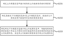
- FIG. 19 is a schematic flowchart of determining uplink feedback information for multiplexing transmission of time-frequency resources used for transmitting uplink data according to an embodiment of the present disclosure.
- FIG. 20 is a schematic flow chart of still another method for transmitting uplink feedback information according to an embodiment of the present disclosure.
- FIG. 21 is a schematic flow chart of still another method for transmitting uplink feedback information according to an embodiment of the present disclosure.
- FIG. 22 is a schematic diagram showing still another uplink feedback information according to an embodiment of the present disclosure.
- FIG. 23 is a schematic block diagram of an uplink feedback information indicating apparatus according to an embodiment of the present disclosure.
- FIG. 24 is a schematic block diagram of another uplink feedback information indicating apparatus according to an embodiment of the present disclosure.
- FIG. 25 is a schematic block diagram of still another uplink feedback information indicating apparatus according to an embodiment of the present disclosure.
- FIG. 26 is a schematic block diagram of still another uplink feedback information indicating apparatus according to an embodiment of the present disclosure.
- FIG. 27 is a schematic block diagram of an uplink feedback information indicating apparatus according to an embodiment of the present disclosure.
- FIG. 28 is a schematic block diagram of another uplink feedback information transmission apparatus according to an embodiment of the present disclosure.
- 29 is a schematic block diagram of a determination module, according to an embodiment of the present disclosure.
- FIG. 30 is a schematic block diagram of an apparatus for uplink feedback information transmission, according to an exemplary embodiment.
- FIG. 31 is a schematic block diagram of an apparatus for uplink feedback information transmission, according to an exemplary embodiment.
- FIG. 1 is a schematic flow chart of an uplink feedback information indication method according to an embodiment of the present disclosure.
- the uplink feedback information indication method shown in this embodiment can be applied to a base station.
- the upstream inverse The feed information indication method may include the following steps.
- step S11 the time-frequency resource used by the user equipment for transmitting the uplink control information is divided into the time-frequency resource set of the at least one uplink control information.
- FIG. 2 is a schematic diagram of a time-frequency resource, according to an embodiment of the present disclosure.
- the size of the uplink control information indicated by the downlink scheduling information sent by the base station to the user equipment is 2 bits
- the time-frequency resources used for transmitting the uplink control information may be four types, for example, as shown in FIG.
- a slot n one slot includes 14 symbols
- the time-frequency resources used by the user equipment for transmitting uplink control information include the first time-frequency resource 1, the second time-frequency resource 2, and the second time-frequency resource Three time-frequency resources 3 and fourth time-frequency resources 4.
- the rules of the partitioning of the set may be pre-configured by the protocol to the base station and the user equipment, or may be set by the base station as needed.
- the base station side configures the set partitioning rule according to the requirement
- the base station may send the set partitioning rule to the user equipment, or may send the set partitioning result to the user equipment, and may also send the set dividing rule and the dividing result to the User equipment.
- the resources in the slot n are divided into one set, and the set 1 includes the first time-frequency resource 1, the second time-frequency resource 2, the third time-frequency resource 3, and the fourth time-frequency resource. 4.
- all the resources in the slot n are divided into two sets.
- the set 1 includes the first time-frequency resource 1 and the second time-frequency resource 2
- the set 2 includes the third time-frequency resource 3 and the fourth.
- all resources in the slot n are divided into three sets, for example, the set 1 includes the first time-frequency resource 1, the set 2 includes the second time-frequency resource 2, and the set 3 includes the third time-frequency resource 3. And the fourth time-frequency resource 4.
- division rule of the set is not limited to the above three modes, and is not limited to the division of the above four time-frequency resources, and details are not described herein again.
- step S12 the uplink feedback information is counted according to a preset manner according to the set to which the time-frequency resource used by the uplink feedback information corresponding to the downlink data of the user equipment belongs.
- the uplink feedback information may be included in the uplink control information.
- the uplink feedback information may be HARQ (Hybrid Automatic Repeat reQuest) uplink feedback information.
- the preset manner may include multiple types, such as a preset sequence of cells, a number of carrier frequencies, a time sequence, and the like.
- the order of the preset cells is cell 1, cell 2, and cell 3. Then, the uplink feedback information of the cell 1 may be counted first, and then the uplink feedback information of the cell 2 is counted. The uplink feedback information of the cell 3 is counted, and the count value corresponding to the cell 1 to the cell 3 is incremented according to the number of the uplink feedback information recorded.
- the time-frequency resource used for uplink feedback information transmission corresponding to the downlink data of the user equipment may be determined according to DCI (Downlink Control Information).
- DCI Downlink Control Information
- the time-frequency resources used for the uplink feedback information transmission corresponding to the downlink data indicated by the DCI1, the DCI3, and the DCI4 are the uplinks corresponding to the downlink data indicated by the first time-frequency resource 1, and the DCI2 and the DCI6.
- the time-frequency resource used for the transmission of the feedback information is the first time-frequency resource 2
- the time-frequency resource used for the uplink feedback information transmission corresponding to the downlink data indicated by the DCI 5 is the third time-frequency resource 3
- the downlink data indicated by the DCI 7 corresponds to the downlink data.
- the time-frequency resource used for the uplink feedback information transmission is the fourth time-frequency resource 4.
- the first time-frequency resource 1, the second time-frequency resource 2, the third time-frequency resource 3, and the fourth time-frequency resource 4 belong to the same set, and the uplink feedback information indicated by DCI1 to DCI7 is continuously counted. Since the size of the uplink control information is 2 bits, the count is 1, 2, 3, 0, 1, 2, 3.
- the first time-frequency resource 1 and the second time-frequency resource 2 belong to the set 1, and the uplink feedback information indicated by DCI1 to DCI4 and DCI6 needs to be continuously counted, and the count is 1, 2, 3, 0, 1;
- the third time-frequency resource 3 and the fourth time-frequency resource 4 belong to the set 2, and the uplink feedback information indicated by the DCI 5 and the DCI 7 needs to be continuously counted, and the count is 1, 2. Further, the count values are sorted into 1, 2, 3, 0, 1, 1, 2 according to the order of DCI1 to DCI7.
- the first time-frequency resource 1 belongs to the set 1.
- the uplink feedback information indicated by the DCI1, the DCI3, and the DCI4 needs to be continuously counted, and the count is 1, 2, and 3.
- the second time-frequency resource 2 belongs to the set 2, and the uplink feedback information indicated by the DCI2 and the DCI6 needs to be continuously counted, and the count is 1, 2;
- the third time-frequency resource 3 and the fourth time-frequency resource 4 belong to the set 3, and the DCI 5 and
- the uplink feedback information indicated by DCI7 is continuously counted, and the count value is 1,2. Further, the count values are sorted into 1, 1, 2, 3, 1, 2, 2 in accordance with the order of DCI1 to DCI7.
- step S13 when transmitting downlink scheduling information and/or uplink scheduling information, the current count value is transmitted to the user equipment.
- the current count value refers to the maximum count value of the continuous count of the uplink feedback information indicated by the DCI when the base station transmits the downlink scheduling information and/or the uplink scheduling information, and the number of the current count value and the number of sets. equal. For example, based on the foregoing manner 1, the current count value is one, and the current count value is 3; for example, based on the foregoing manner 2, the current count value is two, and the current count value is 1 and 2; for example, based on the foregoing manner 3, the current The number of count values is three, and the current count values are 3, 2, and 2.
- the user equipment may receive the division rule and/or the division result of the time-frequency resource set of the uplink control information according to the pre-configuration, and may also receive the division rule of the time-frequency resource set of the uplink control information from the base station and/or Divide the results. For example, the user equipment can determine the result of the division of the time-frequency resource set of the uplink control information, and the user equipment can determine the time-frequency resource used for multiplexing and transmitting the uplink data according to the current count value.
- the number of the uplink feedback information transmitted, and the number of the uplink feedback information that is transmitted by the user equipment to the time-frequency resource used for transmitting the uplink data, and the number of the downlink data corresponding to the uplink feedback information sent by the base station are the same, and the user equipment is guaranteed. Good communication with the base station.
- FIG. 3 is a schematic flowchart of another method for indicating an uplink feedback information according to an embodiment of the present disclosure. As shown in FIG. 3, on the basis of the embodiment shown in FIG. 1, the method for indicating the uplink feedback information further includes:
- Step S14 notifying the user equipment of a set division rule and/or a division result of the time-frequency resource used by the uplink control information transmission.
- the rules and/or partitioning results of the partitioning of the set may be set by the base station as needed.
- the base station may send the segmentation rule of the set to the user equipment, or may send the segmentation result of the set to the user equipment, and may also send the partitioning rule of the set and the segmentation result to the user equipment.
- step S14 the execution sequence may be set as needed, for example, may be performed before step S13, or may be performed simultaneously with step S13.
- FIG. 4 is a schematic flowchart of still another method for indicating an uplink feedback information according to an embodiment of the present disclosure.
- the time-frequency resource used by the user equipment for transmitting uplink control information is divided into a time-frequency resource set used for at least one uplink control information transmission.
- step S111 the division of the set is performed according to the start and/or end position of the time-frequency resource of the uplink control information in the time domain;
- step S112 according to the time unit of the time-frequency resource of the uplink control information in the time domain The division of the set is performed.
- the collection of the collections can be varied.
- the time-frequency resources with the same starting position in the time domain can be divided into one set.
- the start times of the first time-frequency resource 1 and the second time-frequency resource 2 are the same, and the start times of the third time-frequency resource 3 and the fourth time-frequency resource 4 are the same,
- the first time-frequency resource 1 and the second time-frequency resource 2 are divided into one set, and the third time-frequency resource 3 and the fourth time-frequency resource 4 are divided into one set.
- the time-frequency resources belonging to the same time unit may be divided into one set.
- the time unit is a time slot (it should be noted that the time unit can be set as needed), the first time-frequency resource 1, the second time-frequency resource 2, and the third time-frequency resource 3
- the fourth time-frequency resource 4 belongs to the same time slot, and the first time-frequency resource 1, the second time-frequency resource 2, the third time-frequency resource 3, and the fourth time-frequency resource 4 may be divided into one set.
- FIG. 5 is a schematic flowchart of still another method for indicating an uplink feedback information according to an embodiment of the present disclosure. As shown in FIG. 5, on the basis of the embodiment shown in FIG. 1, the counting the uplink feedback information according to a preset manner includes:
- step S121 the uplink feedback information in different sets are respectively counted according to a preset manner.
- the uplink feedback information of different combinations may be separately counted.
- the first time-frequency resource 1 and the second time-frequency resource 2 belong to the set 1 and need to be indicated by DCI1 to DCI4 and DCI6.
- the uplink feedback information is continuously counted, and the count is 1, 2, 3, 0, 1; the third time-frequency resource 3 and the fourth time-frequency resource 4 belong to the set 2, and the uplink feedback information indicated by the DCI 5 and the DCI 7 needs to be continuously counted.
- the count is 1,2. Further, the count values are sorted into 1, 2, 3, 0, 1, 1, 2 according to the order of DCI1 to DCI7.
- the user equipment can quickly determine the number of downlink scheduling information that should be included in the set corresponding to the current count value according to the current count value.
- the downlink scheduling information is DCI
- the current count values received based on the foregoing manner are 1 and 2, so that it is possible to determine that five DCIs of the corresponding set 1 need to be received, and receive the corresponding set 2 2 DCIs.
- the transmitting the current count value to the user equipment includes:
- step S131 Determining, in step S131, the first set to which the time-frequency resource used in the uplink feedback information transmission corresponding to the downlink scheduling information belongs, and selecting the current count value corresponding to the first set to be transmitted to the User equipment.
- the uplink feedback information corresponding to the downlink scheduling information may be determined, and the first set of the time-frequency resources used by the uplink feedback information transmission in the divided set is further determined.
- a set may be a set or multiple sets, and the current count value corresponding to the first set may be transmitted to the user equipment. For other sets than the first set, since the time-frequency resources used by the uplink feedback information transmission do not belong to the set, the time-frequency resources used for the uplink data are not involved, and the user equipment is not required to be notified. Helps reduce the amount of data transferred.
- step S132 selecting one or more time-frequency resources used for uplink data transmission corresponding to the uplink scheduling information, and time-frequency resources used for transmission of uplink control information included in different sets The corresponding current count value is transmitted to the user equipment.
- the uplink scheduling information may select one or more current count values corresponding to the combination of the uplink scheduling information to be transmitted to the user equipment, instead of The current count value corresponding to all the sets is transmitted to the user equipment.
- FIG. 7 is a schematic flowchart of still another method for indicating an uplink feedback information according to an embodiment of the present disclosure. As shown in FIG. 7, in the case of the embodiment shown in FIG. 6, in the case that the selected current count value is multiple, the method further includes:
- step S15 the selected number of the current count values is transmitted to the user equipment.
- the number of the selected current count value may be transmitted to the user equipment, so that the user equipment determines whether to miss the count value according to the number and the received count value, and when it is determined that the current count value is missed,
- the user equipment may send a request to the base station to request the base station to retransmit the current count value.
- FIG. 8 is a schematic flowchart of still another method for indicating an uplink feedback information according to an embodiment of the present disclosure. As shown in FIG. 8, on the basis of the embodiment shown in FIG. 6, the selecting one or more corresponding current count values to be transmitted to the user equipment includes:
- step S1321 when the time-frequency resource used in the uplink data transmission overlaps with the time-frequency resource used in any uplink control information transmission included in the second set in the set, the time-frequency resource is selected. Place The current count value corresponding to the second set is transmitted to the user equipment.
- the second set is one or a plurality of sets in the divided set, and the set in the second set may be the same as the first set, or may be different from the first set.
- the time-frequency resource used for the uplink control information transmission included in the divided different sets may be determined, and when the set is divided.
- the time-frequency resource used for the uplink control information included in the second set and the time-frequency resource used for the uplink data transmission overlap in the time domain, it is necessary to multiplex the time-frequency resources used for the uplink data transmission.
- the set of the time-frequency resources used for the transmission of the uplink control information and the time-frequency resources used for the uplink data transmission it is not necessary to multiplex the time-frequency resources used for the uplink data transmission. Therefore, only the current count value corresponding to the second set to which the time-frequency resource used by the overlapped uplink control information belongs can be transmitted to the user equipment, which is advantageous for reducing the amount of data to be transmitted.
- step S1322 the current count value corresponding to each of the sets is transmitted to the user equipment.
- the count value corresponding to each set may be directly transmitted to the user equipment to reduce the resources consumed by the base station analysis.
- FIG. 9 is a schematic flowchart of still another method for indicating an uplink feedback information according to an embodiment of the present disclosure. As shown in FIG. 9, in the case of the embodiment shown in FIG. 6, in the case that the selected current count value is multiple, the method for indicating the uplink feedback information further includes:
- step S16 the order of the count values is determined.
- the user equipment may determine the order of the received multiple current count values by transmitting the order of the current count value to the user equipment, for example based on FIG. 1
- three current count values, 3, 2, and 2 can be received.
- the user equipment can determine the division rule and/or the division result of the set, when the user equipment cannot determine the order of the three current count values, the current count value 2 may be used as the first count value, and then the set 1 is determined.
- the corresponding time-frequency resources correspond to two uplink feedback information, and in fact, the base station needs the user equipment to correspond to three uplink feedback information in the time-frequency resources corresponding to the set 1, thereby causing communication problems between the user equipment and the base station.
- the user equipment can accurately determine the number of uplink feedback information corresponding to the time-frequency resources in the corresponding set of the current count value, thereby ensuring that the user equipment and the base station are in good condition. Communication.
- the step S16 may set the execution order as needed, may be performed before step S13, or may be performed simultaneously with step S13.
- FIG. 10 is a schematic flowchart of still another method for indicating an uplink feedback information according to an embodiment of the present disclosure. As shown in FIG. 10, on the basis of the embodiment shown in FIG. 9, the order of determining the count value includes:
- step S161 the order of the count values is determined according to a configuration order of the set corresponding to the current count value when dividing the set.
- the order in which the current count values correspond may be the same as the configuration order of the sets when the set is divided with the base station. For example, based on the third method shown in FIG. 1 , if the configuration order of the set is set 1, set 2, and set 3, the current count value is in the order of 3, 2, and 2, and if the set configuration order is set 2, set 3, Set 1, then the current count value is in the order 2, 2, 3.
- FIG. 11 is a schematic flowchart of still another method for indicating an uplink feedback information according to an embodiment of the present disclosure. As shown in FIG. 11, on the basis of the embodiment shown in FIG. 9, the order of determining the count value includes:
- step S162 the order of the count values is determined according to the position of the time-frequency resource used in the uplink control information transmission in the set in the time-frequency and/or frequency domain.
- the current count value may be in the same order as the position of the time-frequency resource used in the uplink control information transmission in the set in the time-frequency and/or frequency domain.
- the location of the time-frequency resource used in the uplink control information transmission in the set is taken as an example, based on the second mode shown in FIG. 1 , where the set 1 includes the first time-frequency resource 1 and the second time-frequency resource 2, The third time-frequency resource 3 and the fourth time-frequency resource 4 included in the set 2 are located higher in the time domain, so the order of determining the count value may be the current count value corresponding to the set 1 and the current corresponding to the set 2 Count value.
- FIG. 12 is a schematic flowchart of still another method for indicating an uplink feedback information according to an embodiment of the present disclosure. As shown in FIG. 12, on the basis of the embodiment shown in FIG. 9, the method for indicating the uplink feedback information further includes:
- step S17 the sequence is notified to the user equipment.
- the order of the count values may be notified by the base station to notify the user equipment.
- the order of the count values can be pre-configured to the user equipment without base station notification.
- FIG. 13 is a schematic flow chart of an uplink feedback information transmission method according to an embodiment of the present disclosure.
- the uplink feedback information transmission method shown in this embodiment may be applied to a user equipment.
- the uplink feedback information transmission method may include the following steps.
- step S31 according to the same division rule and/or division result as the set of time-frequency resources used by the base station for uplink control information transmission, time-frequency resource division for transmitting uplink control information that can be used by the user equipment is used.
- step S32 when receiving downlink scheduling information and/or uplink scheduling information, receiving a current count value sent by the base station;
- step S33 according to the current count value, the time-frequency resource used by the transmission uplink feedback information indicated by the downlink scheduling information, the division rule and/or the division result of the set, and the transmission uplink indicated by the uplink scheduling information.
- the time-frequency resource used by the data determining uplink feedback information for multiplexing the time-frequency resource used for transmitting the uplink data for transmission;
- step S34 multiplexing the time-frequency resources used by the uplink data transmission to transmit the uplink feedback information to the base station.
- the user equipment may divide the time-frequency resources of the transmission uplink control information available to the user equipment according to rules and/or results of the time-frequency resource division set used by the base station for uplink control information transmission. Based on this, the time-frequency resource used for the uplink control information transmission included in the set divided by the base station corresponds to the time-frequency resource used for transmitting the uplink control information included in the set divided by the user.
- the first set of base station allocation includes the number of time-frequency resources used by the uplink control information transmission, the time domain location, the frequency domain location, and the time-frequency of the first set of user equipment partitions for transmitting uplink control information. The number of resources, the time domain location, and the frequency domain location are all the same.
- the user equipment may further receive the current count value sent by the base station, and according to the current count value, the user equipment may determine the number of uplink feedback information that needs to be multiplexed to transmit the time-frequency resources used for transmitting the uplink data.
- the time-frequency resource used for transmitting the uplink feedback information may be determined.
- the time-frequency resource used for transmitting the uplink data may be determined according to the time-frequency resource used for transmitting the uplink data indicated by the uplink scheduling information. Therefore, it can be determined whether there is overlap between the time-frequency resource used for transmitting the uplink feedback information and the time-frequency resource used for transmitting the uplink data, and there is a set corresponding to the time-frequency resource used by the overlapping transmission uplink feedback information.
- the uplink feedback information that overlaps with the time-frequency resource used for transmitting the uplink data may be
- the uplink feedback information corresponding to the used time-frequency resource is determined as uplink feedback information that needs to be multiplexed to transmit time-frequency resources used for transmitting uplink data.
- the uplink feedback information corresponding to the time-frequency resource used for each transmission uplink data in the set corresponding to the used time-frequency resource may be determined as the time-frequency used for multiplexing and transmitting the uplink data.
- the user equipment may transmit uplink feedback information that needs to be multiplexed to transmit time-frequency resources used for transmitting uplink data, and transmit the same on the time-frequency resource used for transmitting the uplink data in the set divided by the base station.
- the number of uplink feedback information is the same as the number of uplink feedback information required by the base station, so that good communication between the user equipment and the base station can be ensured.
- FIG. 14 is a schematic diagram of transmitting uplink feedback information according to an embodiment of the present disclosure.
- the set of divisions is one, and the current count value of the transmission is 3. Then, it can be determined that the number of uplink feedback information that needs to be transmitted to the base station is seven, and that the time-frequency resources used for the transmission uplink feedback information included in the set 1 (that is, 1, 2, 3, and 4 in FIG. 14)
- the time-frequency resources 5 used for transmitting the uplink data overlap that is, there is overlap between 1 and 2 and 5
- the uplink feedback information corresponding to the used time-frequency resources of each of the uplink feedback information in the set 1 can be determined as
- the uplink feedback information for transmitting the time-frequency resources used for transmitting the uplink data needs to be multiplexed.
- the uplink feedback information 6 (the number of which is multiplexed) for multiplexing the time-frequency resources used for transmitting the uplink data can be multiplexed and transmitted to the base station in the time-frequency resource 5 for transmitting the uplink data, so that the first time-frequency resource 1 is The uplink feedback information does not need to be transmitted in the second time-frequency resource 2, the third time-frequency resource 3, and the fourth time-frequency resource 4.
- the uplink feedback information 6 may be sorted according to the order of the DCI, that is, the time-frequency resource for transmitting the uplink data.
- the uplink feedback information may be sorted in the order of DCI1 to DCI7.
- the user equipment may also receive the current count value sent by the base station and the current count value.
- FIG. 14 corresponds to the third mode in the embodiment shown in FIG. 1, and then the set of divisions is three, and the corresponding current count value is 3, 2, and 2.
- the user equipment determines that the current count value is arranged in the order of 3, 2, and 2, and further determines that the uplink feedback information corresponding to the set 1 corresponds to DCI1, DCI3, and DCI4 according to the partitioning result of the set, and the set 2
- the corresponding uplink feedback information corresponds to the DCI2 and the DCI6, and the uplink feedback information corresponding to the set 3 corresponds to the DCI5 and the DCI7, so that the uplink and/or the frequency domain of the time-frequency resource 5 for transmitting the uplink data may be uplinked according to the DCI corresponding to the set.
- the feedback information is sorted, that is, according to DCI1, DCI3, DCI4, DCI2, DCI6, DCI5 and DCI7 respectively sort the uplink feedback information.
- FIG. 15 is a schematic diagram of another transmission uplink feedback information according to an embodiment of the present disclosure.
- the set of divisions is two, and the current count values of the transmission are 1 and 2.
- the number of uplink feedback information that needs to be transmitted to the base station is determined to be 7, and the time-frequency resources used for the transmission uplink feedback information included in the set 1 (that is, 1, 2 in FIG. 15) and the uplink data are transmitted.
- the used time-frequency resources 5 overlap, and the transmission uplink feedback information included in the set 2 does not overlap with the used time-frequency resources (ie, 3, 4 in FIG. 15) and the time-frequency resources 5 used to transmit the uplink data. Therefore, the uplink feedback information corresponding to the time-frequency resources (ie, 1, 2 in FIG.
- the time-frequency resources used to transmit the uplink data may be determined to be required to be reused.
- the uplink feedback information for transmitting the time-frequency resources used by the uplink data for transmission Therefore, the uplink feedback information 6 (the number of five) for multiplexing the time-frequency resources used for transmitting the uplink data can be multiplexed and transmitted to the base station in the time-frequency resource 5 for transmitting the uplink data. Therefore, the first time-frequency resource 1 and the second time-frequency resource 2 do not have to transmit uplink feedback information.
- the uplink feedback information corresponding to the time-frequency resource 4 is multiplexed and transmitted in the time-frequency resource 5 used for transmitting the uplink data, and the uplink corresponding to the third time-frequency resource 3 and the fourth time-frequency resource 4 may be transmitted in a time division multiplexing manner. Feedback.
- FIG. 16 is a schematic diagram of still another transmission uplink feedback information according to an embodiment of the present disclosure.
- the set of divisions is one, and the current count value of the transmission is 3.
- the number of uplink feedback information that needs to be transmitted to the base station is determined to be 7, and the time-frequency resources (ie, 2, 3, and 4 in FIG. 16) used for the transmission uplink feedback information included in the set 1 are transmitted and uplinked.
- the time-frequency resources 5 used in the data overlap. Therefore, the uplink feedback information corresponding to the used time-frequency resources in each of the uplink feedback information in the set 1 can be determined as the time-frequency resource used for multiplexing and transmitting the uplink data for transmission. Upstream feedback information.
- the uplink feedback information 6 (the number of 7) for multiplexing the time-frequency resources used for transmitting the uplink data can be multiplexed and transmitted to the base station in the time-frequency resource 5 for transmitting the uplink data. Therefore, it is not necessary to transmit uplink feedback information in the first time-frequency resource 1, the second time-frequency resource 2, the third time-frequency resource 3, and the fourth time-frequency resource 4.
- FIG. 17 is a schematic diagram showing still another uplink feedback information according to an embodiment of the present disclosure.
- the set of divisions is three.
- the current count value of the transfer is 3, 2, 2.
- the time-frequency resource 5 does not overlap, and the transmission uplink feedback information included in the set 2 overlaps with the used time-frequency resource (that is, 2 in FIG.
- the set 3 includes The transmission of the uplink feedback information overlaps the time-frequency resources used (that is, 3 and 4 in FIG. 17) and the time-frequency resources 5 used for transmitting the uplink data, so that the time-frequency resources used in the aggregate 1 and the uplink data can be transmitted. 5
- the uplink feedback information corresponding to the used time-frequency resources ie, 2, 3, and 4 in FIG. 17
- the uplink feedback information corresponding to the time-frequency resources used for multiplexing and transmitting the uplink data is determined to be uplink feedback. information.
- the uplink feedback information 6 (the number of five) for multiplexing the time-frequency resources used for transmitting the uplink data can be multiplexed and transmitted to the base station in the time-frequency resource 5 for transmitting the uplink data. Therefore, it is not necessary to transmit uplink feedback information in the second time-frequency resource 2, the third time-frequency resource 3, and the fourth time-frequency resource 4.
- the first time-frequency resource 3 in the set 1 does not overlap with the time-frequency resource 5 used for transmitting the uplink data in the time domain. Therefore, the uplink feedback information corresponding to the first time-frequency resource 1 does not need to be multiplexed in the uplink.
- the data is transmitted in the time-frequency resource 5 used.
- the dividing rule and/or the dividing result is pre-configured, and/or received from the base station when receiving downlink scheduling information and/or uplink scheduling information.
- FIG. 18 is a schematic flowchart of another uplink feedback information transmission method according to an embodiment of the present disclosure. As shown in FIG. 18, on the basis of the embodiment shown in FIG. 13, if the number of the counts is multiple, the uplink feedback information transmission method further includes:
- step S35 receiving the number of the count values sent by the base station
- step S36 it is determined whether the count value is missed based on the number and the number of received count values.
- the user equipment may count the number of received current count values, and compare with the number sent by the base station, and the number of current count values is smaller than (the case where the base station does not generally appear) It is determined that the current count value is missed, so that a request can be sent to the base station to request the base station to resend the current count value.
- the user equipment may perform uplink transmission according to the retransmitted current count value and the downlink scheduling information.
- a time-frequency resource used by the feedback information, a division rule of the set, and/or a division result the The time-frequency resource used for transmitting the uplink data indicated by the uplink scheduling information determines uplink feedback information for multiplexing the time-frequency resource used for transmitting the uplink data for transmission.
- the method further includes:
- the time-frequency resource used for transmitting the uplink feedback information indicated by the downlink scheduling information, the division rule and/or the division result of the set, and the transmission uplink indicated by the uplink scheduling information, according to the current count value includes:
- the frequency resource and the sequence determine uplink feedback information for multiplexing the time-frequency resource used for transmitting the uplink data for transmission.
- FIG. 19 is a schematic flowchart of determining uplink feedback information for multiplexing transmission of time-frequency resources used for transmitting uplink data according to an embodiment of the present disclosure.
- the uplink feedback information for determining to multiplex the time-frequency resource used for transmitting the uplink data for transmission includes:
- step S33 determining a time-frequency resource used for transmitting uplink data indicated in the uplink scheduling information
- step S332 determining a time-frequency resource set corresponding to the received current count value greater than zero when receiving the downlink scheduling information and/or the uplink scheduling information;
- step S333 the uplink feedback information indicated by the downlink scheduling information is determined, and the time-frequency resource used for the transmission belongs to the uplink feedback information of the time-frequency resource set corresponding to the current count value greater than zero, which is the multiplexed uplink data.
- the current count value is equal to 0 if the current count value is equal to 0, it is determined whether the current count value is really equal to 0 according to an actual situation. For example, it may be detected whether downlink scheduling information indicating uplink feedback information is received, and if received, may determine The current count value is not 0, but an integer multiple of 4. If not received, it can be determined that the count value is indeed zero.
- the base station may be configured to indicate the uplink feedback information corresponding to the resource used by the uplink feedback information in the set, where the uplink data needs to be multiplexed and transmitted.
- Time-frequency resources used For the set corresponding to the current count value of 0, it may be determined that the base station does not indicate the uplink feedback information corresponding to the resource used by the uplink feedback information in the set, and the time-frequency resource used for transmitting the uplink data needs to be multiplexed. Therefore, only the uplink feedback information of the time-frequency resource set corresponding to the current count value greater than zero in the uplink feedback information indicated by the downlink scheduling information may be determined as the multiplexed uplink data time-frequency resource.
- Uplink feedback information, and for other uplink feedback information may be transmitted to the base station in other manners.
- FIG. 20 is a schematic flow chart of still another method for transmitting uplink feedback information according to an embodiment of the present disclosure. As shown in FIG. 20, on the basis of the embodiment shown in FIG. 13, if the time-frequency resources for transmitting the uplink scheduling information are located in different time units, the time-frequency resources used for multiplexing the uplink data transmission are Before the base station transmits the uplink feedback information, the uplink feedback information transmission method further includes:
- step S37 determining, in each time unit of the different time units, uplink feedback information for multiplexing time-frequency resources used for uplink data transmission for transmission;
- the transmitting the uplink feedback information to the base station by using the time-frequency resource used by the uplink data transmission includes:
- step S334 in each time unit of the different time units, according to the uplink feedback information determined in each time unit, the time-frequency resource used by the uplink data transmission is multiplexed in the corresponding time unit.
- the base station transmits the uplink feedback information.
- the corresponding time unit refers to a time unit corresponding to the determined uplink feedback information.
- the uplink feedback information of the time-frequency resources used for multiplexing the uplink data transmission in each time unit may be determined, and then In each time unit, the uplink feedback information used in the uplink data transmission may be multiplexed according to the uplink feedback information in the respective time units and the multiplexing condition of the time-frequency resources used in the uplink data transmission to transmit the uplink feedback information. For example, for the first time unit in the different time units, the time-frequency resources used for the uplink data transmission may be multiplexed according to the multiplexing information of the uplink information and the time-frequency resources used in the uplink data transmission in the first time unit. Upstream feedback information.
- the time-frequency resources used for the uplink data transmission may be multiplexed according to the multiplexing information of the uplink information in the second time unit and the time-frequency resource used in the uplink data transmission to transmit the uplink. Feedback.
- FIG. 21 is a schematic flow chart of still another method for transmitting uplink feedback information according to an embodiment of the present disclosure. As shown in FIG. 21, on the basis of the embodiment shown in FIG. 13, if the time frequency of the uplink scheduling information is transmitted
- the uplink feedback information transmission method further includes: before the multiplexed time-frequency resource used by the uplink data transmission is used to transmit the uplink feedback information to the base station, the uplink feedback information transmission method further includes:
- step S38 determining, in each time unit of the different time units, uplink feedback information for multiplexing time-frequency resources used for uplink data transmission for transmission;
- the transmitting the uplink feedback information to the base station by using the time-frequency resource used by the uplink data transmission includes:
- step S335 in each time unit of the different time units, the uplink feedback information of the time-frequency resource used by the multiplexed uplink data transmission determined in each time unit is combined, and the uplink data transmission is multiplexed.
- the used time-frequency resource transmits the uplink feedback information to the base station.
- uplink feedback information for multiplexing time-frequency resources used for uplink data transmission in each time unit may be determined, and then The uplink feedback information of the time-frequency resources used for multiplexing the uplink data transmission in each time unit is merged, and then the combined uplink feedback information is used in each time unit to multiplex the time-frequency resources used for the uplink data transmission. Transfer. For example, for the first time unit in the different time units, the uplink data transmission in the first time unit and the second time unit and the multiplexing of the time-frequency resources used in the uplink data transmission may be used to multiplex the uplink data transmission. Time-frequency resources to transmit uplink feedback information.
- the uplink information used in the first time unit and the second time unit and the multiplexing of the time-frequency resources used in the uplink data transmission may be used to multiplex the uplink data transmission.
- Time-frequency resources to transmit uplink feedback information may be used to multiplex the uplink feedback information.
- FIG. 22 is a schematic diagram showing still another uplink feedback information according to an embodiment of the present disclosure.
- the uplink feedback information indicated by DCI1, DCI3, and DCI4 corresponds to the first time-frequency resource 1 in the time slot n
- DCI2 and The uplink feedback information indicated by the DCI6 corresponds to the second time-frequency resource 2 in the slot n+1
- the uplink feedback information indicated by the DCI3 corresponds to the third time-frequency resource 3 in the slot n
- the uplink feedback information indicated by the DCI4 corresponds to The fourth time-frequency resource 4 in the slot n+1.
- the division rule of the set is: the set 1 includes the first time-frequency resource 1, the set 2 includes the second time-frequency resource 2, and the set 3 includes the third time-frequency resource 3 and the fourth time-frequency resource 4,
- Determining the uplink feedback information of the time-frequency resource used for multiplexing the uplink data transmission in each time unit of different time units it can be concluded that, in the time slot n, the first time-frequency resource 1 and the uplink data transmission are used. There are overlaps in the time-frequency resources, so DCI1, DCI3, and DCI4 corresponding to the first time-frequency resource 1 are required.
- the corresponding uplink feedback information is multiplexed with the time-frequency resource used for the uplink data transmission; in the time slot n+1, the second time-frequency resource 2 and the time-frequency resource used for the uplink data transmission overlap, and thus
- the uplink feedback information corresponding to the DCI2 and the DCI6 corresponding to the second time-frequency resource 2 multiplexes the time-frequency resources used for the uplink data transmission for transmission.
- the time-frequency resource used for multiplexing the uplink data transmission in the unit transmits the uplink feedback information to the base station. That is, in the time slot n, only the uplink feedback information of the time slot n that needs to be multiplexed with the time-frequency resource used for the uplink data transmission, and the time-frequency resource transmission used for the uplink data transmission of the multiplexed time slot n are transmitted. can.
- the frequency resource can be transmitted.
- the uplink feedback information corresponding to the DCI1, the DCI3, and the DCI4 corresponding to the first time-frequency resource 1 is multiplexed with the time-frequency resource used for the uplink data transmission;
- the uplink feedback information corresponding to the DCI2 and the DCI6 corresponding to the second time-frequency resource 2 is multiplexed with the time-frequency resource used for the uplink data transmission.
- the multiplexed uplink data transmission determined in each time unit is combined.
- the uplink feedback information of the time-frequency resource is multiplexed with the time-frequency resource used for the uplink data transmission to transmit the uplink feedback information to the base station. That is, in the slot n, the uplink feedback information in the slot n that is multiplexed with the time-frequency resource used for the uplink data transmission, and the time-frequency resource used in the slot n+1 and the uplink data transmission are required.
- the multiplexed uplink feedback information is multiplexed with the time-frequency resource transmission used for the uplink data transmission in the slot n.
- the uplink feedback information in the slot n that is multiplexed with the time-frequency resource used for the uplink data transmission, and the need to use the uplink data transmission in the slot n+1 are required.
- the uplink feedback information of the time-frequency resource multiplexing is multiplexed with the time-frequency resource transmission used in the uplink data transmission of the slot n+1.
- the uplink feedback information corresponding to DCI1, DCI3, DCI4, DCI2, and DCI6 is multiplexed with the time-frequency resource used for uplink data transmission; in the time slot n+1, The uplink feedback information corresponding to DCI1, DCI3, DCI4, DCI2, and DCI6 is multiplexed with time-frequency resources used for uplink data transmission.
- time unit referred to in the foregoing embodiment may be a slot, and the time slot is used. Contains 14 symbols, or other time units, such as the length of time containing non-14 symbols as a unit of time.
- the present disclosure further provides an embodiment of the uplink feedback information indication apparatus and the uplink feedback information transmission apparatus.
- FIG. 23 is a schematic block diagram of an uplink feedback information indicating apparatus according to an embodiment of the present disclosure.
- the uplink feedback information indicating apparatus shown in this embodiment may be applied to a base station.
- the uplink feedback information indicating apparatus may include:
- the dividing module 11 is configured to divide the time-frequency resource used by the user equipment for transmitting the uplink control information into the time-frequency resource set of the at least one uplink control information;
- the counting module 12 is configured to count the uplink feedback information according to a preset manner according to the set to which the time-frequency resource used by the uplink feedback information corresponding to the downlink data of the user equipment belongs.
- the counting transmission module 13 is configured to transmit the current count value to the user equipment when transmitting downlink scheduling information and/or uplink scheduling information.
- FIG. 24 is a schematic block diagram of another uplink feedback information indicating apparatus according to an embodiment of the present disclosure. As shown in FIG. 24, on the basis of the embodiment shown in FIG. 23, the uplink feedback information indicating apparatus further includes:
- the division notification module 14 is configured to notify the user equipment of a set division rule and/or a division result of the time-frequency resource used by the uplink control information transmission.
- the dividing module is configured to perform, according to the start and/or end position of the time-frequency resource of the uplink control information, the division of the set according to a start time and/or a stop position of the uplink control information; or according to the time-frequency of the uplink control information.
- the time unit to which the resource belongs in the time domain performs the division of the set.
- the counting module is configured to separately count the uplink feedback information in different sets according to a preset manner.
- the counting transmission module is configured to determine a first set to which the time-frequency resource used by the uplink feedback information transmission corresponding to the downlink scheduling information belongs in the set, and select a corresponding location of the first set Transmitting a current count value to the user equipment; and/or a time-frequency resource used for uplink data transmission corresponding to the uplink scheduling information, and a time-frequency resource used for transmitting uplink control information included in different sets And selecting one or more corresponding current count values to transmit to the user equipment.
- FIG. 25 is a schematic block diagram of still another uplink feedback information indicating apparatus according to an embodiment of the present disclosure. Figure. As shown in FIG. 25, on the basis of the embodiment shown in FIG. 23, the uplink feedback information indicating apparatus further includes:
- the number transmission module 15 is configured to transmit the selected number of the current count values to the user equipment if the selected current count value is multiple.
- the counting transmission module is configured to be configured as a time-frequency resource used by the uplink data transmission, and a time-frequency used by any uplink control information transmission included in the second set in the set
- the current count value corresponding to the second set is selected and transmitted to the user equipment; or the current count value corresponding to each of the sets is respectively transmitted to the user equipment.
- FIG. 26 is a schematic block diagram of still another uplink feedback information indicating apparatus according to an embodiment of the present disclosure. As shown in FIG. 26, on the basis of the embodiment shown in FIG. 23, the uplink feedback information indicating apparatus further includes:
- the sequential transmission module 16 is configured to determine the order of the count values if the selected current count value is multiple.
- the sequence transmission module is configured to determine an order of the count values according to a configuration order of the set corresponding to the current count value when dividing the set.
- the sequential transmission module is configured to determine an order of the count values according to locations of time-frequency resources used in the time-frequency and/or frequency domain according to uplink control information transmission in the set.
- the uplink feedback information indicating apparatus further includes:
- the sequence notification module 97 is configured to notify the user equipment of the sequence.
- FIG. 27 is a diagram showing an uplink feedback information transmission apparatus according to an embodiment of the present disclosure.
- the uplink feedback information transmission apparatus of this embodiment may be applied to a user equipment. As shown in FIG. 27, the apparatus includes:
- the dividing module 21 is configured to use a time-frequency for transmitting uplink control information that can be used by the user equipment according to the same dividing rule and/or dividing result as the set of time-frequency resources used by the base station for uplink control information transmission.
- the resource is divided into a time-frequency resource set of at least one uplink control information;
- the counting receiving module 22 is configured to receive the current count value sent by the base station when receiving the downlink scheduling information and/or the uplink scheduling information;
- the determining module 23 is configured to: according to the current count value, the time-frequency resource used by the uplink information received by the downlink scheduling information, the partitioning rule and/or the segmentation result of the set, and the uplink scheduling information Transmitting time-frequency resources used for uplink data, and determining uplink feedback information for multiplexing the time-frequency resources used for transmitting the uplink data for transmission;
- the transmitting module 24 is configured to multiplex the time-frequency resources used by the uplink data transmission to transmit the uplink feedback information to the base station.
- the dividing rule and/or the dividing result is pre-configured, and/or received from the base station when receiving downlink scheduling information and/or uplink scheduling information.
- FIG. 28 is a schematic block diagram of another uplink feedback information transmission apparatus according to an embodiment of the present disclosure. As shown in FIG. 28, on the basis of the embodiment shown in FIG. 27, the uplink feedback information transmission apparatus further includes:
- the number receiving module 25 is configured to receive the number of the count values sent by the base station if the number of the count values is multiple;
- the miss determination module 26 is configured to determine whether to miss the count value based on the number and the number of received count values.
- the device further includes:
- a number receiving module a sequence receiving module, configured to receive an order of the count values sent by the base station;
- the determining module is configured to: according to the current count value, a time-frequency resource used by the uplink scheduling information indicated by the downlink scheduling information, a dividing rule and/or a dividing result of the set, and the uplink scheduling
- the information indicates the time-frequency resource used for transmitting the uplink data and the sequence, and determines uplink feedback information for multiplexing the time-frequency resource used for transmitting the uplink data for transmission.
- the determining module 23 includes:
- the indication determining submodule 231 is configured to determine a time-frequency resource used by the transmission uplink data indicated in the uplink scheduling information
- the set determining sub-module 232 is configured to determine, when receiving the downlink scheduling information and/or the uplink scheduling information, the received time-frequency resource set corresponding to the current count value greater than zero;
- the multiplexing determination sub-module 233 is configured to determine, in the uplink feedback information indicated by the downlink scheduling information, that the time-frequency resource used for the transmission belongs to the uplink feedback information of the time-frequency resource set corresponding to the current count value greater than zero, Uplink feedback information for multiplexing uplink data time-frequency resources.
- the determining module is further configured to determine when the time-multiplexed data transmission is used in each time unit of the different time unit.
- the transmission module is configured to multiplex the time used for uplink data transmission in the corresponding time unit according to the uplink feedback information determined in each time unit in each time unit of the different time units.
- the frequency resource transmits the uplink feedback information to the base station.
- the determining module is further configured to determine a time frequency used for multiplexing the uplink data transmission in each time unit of the different time unit.
- the transmission module is configured to combine, in each time unit of the different time units, uplink feedback information of time-frequency resources used by the multiplexed uplink data transmission determined in each time unit, The uplink feedback information is transmitted to the base station by using a time-frequency resource used for uplink data transmission.
- the device embodiment since it basically corresponds to the method embodiment, reference may be made to the partial description of the method embodiment.
- the device embodiments described above are merely illustrative, wherein the units described as separate components may or may not be physically separate, and the components displayed as units may or may not be physical units, ie may be located A place, or it can be distributed to multiple network units. Some or all of the modules may be selected according to actual needs to achieve the purpose of the solution of the embodiment. Those of ordinary skill in the art can understand and implement without any creative effort.
- An embodiment of the present disclosure also provides an electronic device, including:
- a memory for storing processor executable instructions
- processor is configured to:
- the time-frequency resource used by the user equipment to transmit the uplink control information is divided into the time-frequency resource set of the at least one uplink control information
- the uplink feedback information is counted according to a preset manner according to the set to which the time-frequency resource used by the uplink feedback information corresponding to the downlink data of the user equipment belongs;
- the current count value is transmitted to the user equipment.
- An embodiment of the present disclosure also provides a sixth aspect, and an electronic device is provided, including:
- a memory for storing processor executable instructions
- processor is configured to:
- the time-frequency resources used by the user equipment for transmitting uplink control information are divided into at least one uplink control according to a same division rule and/or a division result as the set of the time-frequency resources used by the base station for the uplink control information transmission. a collection of time-frequency resources of information;
- Embodiments of the present disclosure also propose a computer readable storage medium having stored thereon a computer program that, when executed by a processor, implements the following steps:
- the time-frequency resource used by the user equipment to transmit the uplink control information is divided into the time-frequency resource set of the at least one uplink control information
- the uplink feedback information is counted according to a preset manner according to the set to which the time-frequency resource used by the uplink feedback information corresponding to the downlink data of the user equipment belongs;
- the current count value is transmitted to the user equipment.
- Embodiments of the present disclosure also propose a computer readable storage medium having stored thereon a computer program that, when executed by a processor, implements the following steps:
- the time-frequency resources used by the user equipment for transmitting uplink control information are divided into at least one uplink control according to a same division rule and/or a division result as the set of the time-frequency resources used by the base station for the uplink control information transmission. a collection of time-frequency resources of information;
- Time-frequency used for transmitting uplink feedback information indicated by the current count value and the downlink scheduling information And determining, by the resource, the dividing rule and/or the dividing result of the set, and the time-frequency resource used for transmitting the uplink data indicated by the uplink scheduling information, determining uplink feedback information for multiplexing the time-frequency resource used for transmitting the uplink data for transmission;
- FIG. 30 is a schematic block diagram of an apparatus 3000 for uplink feedback information transmission, according to an exemplary embodiment.
- the device 3000 can be provided as a base station.
- apparatus 3000 includes a processing component 3022, a wireless transmit/receive component 3024, an antenna component 3026, and a signal processing portion specific to the wireless interface.
- Processing component 3022 can further include one or more processors.
- One of the processing components 3022 can be configured to perform the uplink feedback information indication method described in any of the above embodiments.
- FIG. 31 is a schematic block diagram of an apparatus 3100 for uplink feedback information transmission, according to an exemplary embodiment.
- device 3100 can be a mobile phone, a computer, a digital broadcast terminal, a messaging device, a gaming console, a tablet device, a medical device, a fitness device, a personal digital assistant, and the like.
- apparatus 3100 can include one or more of the following components: processing component 3102, memory 3104, power component 3106, multimedia component 3108, audio component 3110, input/output (I/O) interface 3112, sensor component 3114, And a communication component 3116.
- Processing component 3102 typically controls the overall operation of device 3100, such as operations associated with display, telephone calls, data communications, camera operations, and recording operations.
- Processing component 3102 can include one or more processors 3120 to execute instructions to perform all or part of the steps of the above described methods.
- processing component 3102 can include one or more modules to facilitate interaction between component 3102 and other components.
- the processing component 3102 can include a multimedia module to facilitate interaction between the multimedia component 3108 and the processing component 3102.
- the memory 3104 is configured to store various types of data to support operation at the device 3100. Examples of such data include instructions for any application or method operating on device 3100, contact data, phone book data, messages, pictures, videos, and the like.
- the memory 3104 can be implemented by any type of volatile or non-volatile storage device or a combination thereof, such as static random access memory (SRAM), electrically erasable programmable read only memory (EEPROM), erasable Programmable Read Only Memory (EPROM), Programmable Read Only Memory (PROM), Read Only Memory (ROM), Magnetic Memory, Flash Memory, Disk or Optical Disk.
- SRAM static random access memory
- EEPROM electrically erasable programmable read only memory
- EPROM erasable Programmable Read Only Memory
- PROM Programmable Read Only Memory
- ROM Read Only Memory
- Magnetic Memory Flash Memory
- Disk Disk or Optical Disk.
- Power component 3106 provides power to various components of device 3100.
- Power component 3106 can include a power management system, one or more power sources, and other components associated with generating, managing, and distributing power for device 3100.
- the multimedia component 3108 includes a screen between the device 3100 and the user that provides an output interface screen.
- the screen can include a liquid crystal display (LCD) and a touch panel (TP). If the screen includes a touch panel, the screen can be implemented as a touch screen to receive input signals from the user.
- the touch panel includes one or more touch sensors to sense touches, slides, and gestures on the touch panel. The touch sensor may sense not only the boundary of the touch or sliding action, but also the duration and pressure associated with the touch or slide operation.
- the multimedia component 3108 includes a front camera and/or a rear camera. When the device 3100 is in an operation mode, such as a shooting mode or a video mode, the front camera and/or the rear camera can receive external multimedia data. Each front and rear camera can be a fixed optical lens system or have focal length and optical zoom capabilities.
- the audio component 3110 is configured to output and/or input an audio signal.
- the audio component 3110 includes a microphone (MIC) that is configured to receive an external audio signal when the device 3100 is in an operational mode, such as a call mode, a recording mode, and a voice recognition mode.
- the received audio signal may be further stored in memory 3104 or transmitted via communication component 3116.
- the audio component 3110 also includes a speaker for outputting an audio signal.
- the I/O interface 3112 provides an interface between the processing component 3102 and the peripheral interface module, which may be a keyboard, a click wheel, a button, or the like. These buttons may include, but are not limited to, a home button, a volume button, a start button, and a lock button.
- the sensor assembly 3114 includes one or more sensors for providing a status assessment of various aspects to the device 3100.
- the sensor assembly 3114 can detect an open/closed state of the device 3100, such as a display and a keypad of the device 3100, and the sensor assembly 3114 can also detect a change in position of a component of the device 3100 or device 3100. The presence or absence of contact by the user with the device 3100, the orientation or acceleration/deceleration of the device 3100 and the temperature change of the device 3100.
- Sensor assembly 3114 can include a proximity sensor configured to detect the presence of nearby objects without any physical contact.
- Sensor assembly 3114 may also include a light sensor, such as a CMOS or CCD image sensor, for use in imaging applications.
- the sensor assembly 3114 can also include an acceleration sensor, a gyro sensor, a magnetic sensor, a pressure sensor, or a temperature sensor.
- Communication component 3116 is configured to facilitate wired or wireless communication between device 3100 and other devices.
- the device 3100 can access a wireless network based on a communication standard, such as WiFi, 2G or 3G, or a combination thereof.
- communication component 3116 receives broadcast signals or broadcast associated information from an external broadcast management system via a broadcast channel.
- the communication component 3116 also includes a near field communication (NFC) module to facilitate short range communication.
- NFC can be based on radio frequency identification (RFID) technology.
- RFID radio frequency identification
- IrDA Infrared Data Association
- UWB ultra-wideband
- Bluetooth Bluetooth
- device 3100 may be implemented by one or more application specific integrated circuits (ASICs), digital signal processors (DSPs), digital signal processing devices (DSPDs), programmable logic devices (PLDs), field programmable A gate array (FPGA), a controller, a microcontroller, a microprocessor, or other electronic component implementation for performing the uplink feedback information transmission method described in any of the above embodiments.
- ASICs application specific integrated circuits
- DSPs digital signal processors
- DSPDs digital signal processing devices
- PLDs programmable logic devices
- FPGA field programmable A gate array
- controller a controller
- microcontroller a microcontroller
- microprocessor or other electronic component implementation for performing the uplink feedback information transmission method described in any of the above embodiments.
- non-transitory computer readable storage medium comprising instructions, such as a memory 3104 comprising instructions executable by processor 3120 of apparatus 3100 to perform the above method.
- the non-transitory computer readable storage medium may be a ROM, a random access memory (RAM), a CD-ROM, a magnetic tape, a floppy disk, and an optical data storage device.
Landscapes
- Engineering & Computer Science (AREA)
- Signal Processing (AREA)
- Computer Networks & Wireless Communication (AREA)
- Mobile Radio Communication Systems (AREA)
Abstract
本公开提出了上行反馈信息指示方法,包括:将用户设备可以使用的用于传输上行控制信息的时频资源划分为至少一个上行控制信息的时频资源集合;将上行控制信息传输时频资源的集合划分规则和/或划分结果通知用户设备;根据用户设备的下行数据对应的上行反馈信息传输所使用的时频资源所属的集合,按照预设方式对上行反馈信息进行计数;在传输下行调度信息数据和/或上行调度信息时,将当前计数值传输至用户设备。根据本公开的实施例,可以保证用户设备复用传输上行数据使用的时频资源进行传输的上行反馈信息的数目,与基站发送的与上行反馈信息对应的下行数据的数目相同,保证用户设备和基站之间良好地通信。
Description
本申请涉及通信技术领域,具体而言,涉及上行反馈信息指示方法、上行反馈信息指示装置、上行反馈信息传输方法、上行反馈信息传输装置、电子设备和计算机可读存储介质。
在用户设备和基站交互的过程中,若用户设备传输的数据和上行控制信息在时域上存在重叠,用户设备可以复用传输数据的时频资源,在传输数据的时频资源上传输上行控制信号,即UCI piggyback(Uplink control information piggyback,上行控制信息背负)。当在传输数据的时频资源上传输上行控制信号时,针对上行控制信息中的上行反馈信息,可能存在基站和用户设备对于上行反馈信息数目等内容认知不一致的问题。
为了解决上述问题,在LTE(Long Term Evolution,长期演进)中,引入了DAI(Downlink Assignment Indicator,下行链路分配指示)机制,主要是在下行调度信息中引入DAI_counter,在上行调度信息中引入DAI_Total,其中,DAI_counter的值用于指示需要和上行数据在同一个子帧中传输的下行数据对应的上行反馈信息的数目,DAI_Total的值等于最近一次变化的DAI_counter的值。基于此,用户设备可以通过根据DAI_Total的值确定下行调度信息是否漏接,以及需要和上行数据在同一个子帧向基站传输的上行反馈信息的数目。
由于在LTE中,上行数据和上行控制信息都是以子帧为单位传输的,这使得上行控制信息和上行数据在时域上或者全部重叠,或者没有重叠,而不存在部分重叠的情况,所以DAI_counter是针对时域与上行数据所在的子帧内全部冲动和的上行反馈信息的计数。
但是在NR(New Radio,新空口)中,上行数据和上行控制信息并不以固定单位传输,有可能存在上行数据和上行控制信息在时域上部分重叠的情况,或者两个上行反馈信息在时域上不重叠,而却分别与一个上行数据在时域上重叠的情况。针对这种情况,按照相关技术中的机制将无法确定DAI_counter的值,进而也无法确定
DAI_Total的值,从而使得用户设备无法确定和上行数据在同一个子帧向基站传输的上行反馈信息的数目。
发明内容
有鉴于此,本公开提出了上行反馈信息指示方法、上行反馈信息指示装置、上行反馈信息传输方法、上行反馈信息传输装置、电子设备和计算机可读存储介质。
根据本公开的第一方面,提出一种上行反馈信息指示方法,适用于基站,所述方法包括:
将用户设备可以使用的用于传输上行控制信息的时频资源划分为至少一个上行控制信息的时频资源集合;
将所述上行控制信息传输时频资源的集合划分规则和/或划分结果通知所述用户设备;
根据所述用户设备的下行数据对应的上行反馈信息传输所使用的时频资源所属的所述集合,按照预设方式对所述上行反馈信息进行计数;
在传输下行调度信息数据和/或上行调度信息时,将当前计数值传输至所述用户设备。
根据本公开的第二方面,提出一种上行反馈信息传输方法,适用于用户设备,所述方法包括:
按照与基站对于上行控制信息传输所使用的时频资源的集合相同的划分规则和/或划分结果或者基站通知的划分结果,将所述用户设备可以使用的用于传输上行控制信息的时频资源划分为至少一个上行控制信息的时频资源集合;
在接收下行调度信息数据调度和/或上行数据调度信息时,接收基站发送的当前计数值;
根据所述当前计数值,所述下行数据调度信息指示的传输上行反馈信息使用的时频资源,所述上行控制信息传输时频资源集合的划分规则和/或划分结果,以及所述上行数据调度信息指示的传输上行数据使用的时频资源,确定以及所述划分规则和/或划分结果确定所述上行反馈信息在传输时所使用的时频资源;复用所述传输上行数据使用的时频资源进行传输的上行反馈信息;
在复用所述确定上行数据传输所使用的时频资源向所述基站传输所述上行反馈信息。
根据本公开的第三方面,提出一种上行反馈信息指示装置,适用于基站,所述装置包括:
划分模块,被配置为将用户设备可以使用的用于传输上行控制信息的时频资源划分为至少一个上行控制信息的时频资源集合;
计数模块,被配置为根据所述用户设备的下行数据对应的上行反馈信息传输所使用的时频资源所属的所述集合,按照预设方式对所述上行反馈信息进行计数;
计数传输模块,被配置为在传输下行调度信息和/或上行调度信息时,将当前计数值传输至所述用户设备。
根据本公开的第四方面,提出一种上行反馈信息传输装置,适用于用户设备,所述装置包括:
划分模块,被配置为按照与基站对于上行控制信息传输所使用的时频资源的集合相同的划分规则和/或划分结果,将所述用户设备可以使用的用于传输上行控制信息的时频资源划分为至少一个上行控制信息的时频资源集合;
计数接收模块,被配置为在接收下行调度信息和/或上行调度信息时,接收基站发送的当前计数值;
确定模块,被配置为根据所述当前计数值、所述下行调度信息指示的传输上行反馈信息使用的时频资源、所述集合的划分规则和/或划分结果、所述上行调度信息指示的传输上行数据使用的时频资源,确定复用所述传输上行数据使用的时频资源进行传输的上行反馈信息;
传输模块,被配置为复用所述上行数据传输所使用的时频资源向所述基站传输所述上行反馈信息。
根据本公开的第五方面,提出一种电子设备,包括:
处理器;
用于存储处理器可执行指令的存储器;
其中,所述处理器被配置为:
将用户设备可以使用的用于传输上行控制信息的时频资源划分为至少一个上行控制信息的时频资源集合;
根据所述用户设备的下行数据对应的上行反馈信息传输所使用的时频资源所属的所述集合,按照预设方式对所述上行反馈信息进行计数;
在传输下行调度信息和/或上行调度信息时,将当前计数值传输至所述用户设备。
根据本公开的第六方面,提出一种电子设备,包括:
处理器;
用于存储处理器可执行指令的存储器;
其中,所述处理器被配置为:
按照与基站对于上行控制信息传输所使用的时频资源的集合相同的划分规则和/或划分结果,将所述用户设备可以使用的用于传输上行控制信息的时频资源划分为至少一个上行控制信息的时频资源集合;
在接收下行调度信息和/或上行调度信息时,接收基站发送的当前计数值;
根据所述当前计数值、所述下行调度信息指示的传输上行反馈信息使用的时频资源、所述集合的划分规则和/或划分结果、所述上行调度信息指示的传输上行数据使用的时频资源,确定复用所述传输上行数据使用的时频资源进行传输的上行反馈信息;
复用所述上行数据传输所使用的时频资源向所述基站传输所述上行反馈信息。
根据本公开的第七方面,提出一种计算机可读存储介质,其上存储有计算机程序,该程序被处理器执行时实现以下步骤:
将用户设备可以使用的用于传输上行控制信息的时频资源划分为至少一个上行控制信息的时频资源集合;
根据所述用户设备的下行数据对应的上行反馈信息传输所使用的时频资源所属的所述集合,按照预设方式对所述上行反馈信息进行计数;
在传输下行调度信息和/或上行调度信息时,将当前计数值传输至所述用户设备。
根据本公开的第八方面,提出一种计算机可读存储介质,其上存储有计算机程
序,该程序被处理器执行时实现以下步骤:
按照与基站对于上行控制信息传输所使用的时频资源的集合相同的划分规则和/或划分结果,将所述用户设备可以使用的用于传输上行控制信息的时频资源划分为至少一个上行控制信息的时频资源集合;
在接收下行调度信息和/或上行调度信息时,接收基站发送的当前计数值;
根据所述当前计数值、所述下行调度信息指示的传输上行反馈信息使用的时频资源、所述集合的划分规则和/或划分结果、所述上行调度信息指示的传输上行数据使用的时频资源,确定复用所述传输上行数据使用的时频资源进行传输的上行反馈信息;
复用所述上行数据传输所使用的时频资源向所述基站传输所述上行反馈信息。
根据本公开的实施例,由于用户设备可以根据预先配置确定上行控制信息的时频资源集合的划分规则和/或划分结果,也可以从基站接收上行控制信息的时频资源集合的划分规则和/或划分结果。以用户设备可以确定上行控制信息的时频资源集合的划分结果为例,通过将当前计数值传输至用户设备,使得用户设备可以根据当前计数值确定需要复用传输上行数据使用的时频资源进行传输的上行反馈信息的数目,进而保证用户设备复用传输上行数据使用的时频资源进行传输的上行反馈信息的数目,与基站发送的与上行反馈信息对应的下行数据的数目相同,保证用户设备和基站之间良好地通信。
为了更清楚地说明本申请实施例中的技术方案,下面将对实施例描述中所需要使用的附图作简单地介绍,显而易见地,下面描述中的附图仅仅是本申请的一些实施例,对于本领域普通技术人员来讲,在不付出创造性劳动性的前提下,还可以根据这些附图获得其他的附图。
图1是根据本公开一个实施例示出的一种上行反馈信息指示方法。本实施所示的上行反馈信息指示可以应用于基站。
图2是根据本公开一个实施例示出的一种时频资源的示意图。
图3是根据本公开一个实施例示出的另一种上行反馈信息指示方法的示意流程图。
图4是根据本公开一个实施例示出的又一种上行反馈信息指示方法的示意流程
图。
图5是根据本公开一个实施例示出的又一种上行反馈信息指示方法的示意流程图。
图6是根据本公开一个实施例示出的又一种上行反馈信息指示方法的示意流程图。
图7是根据本公开一个实施例示出的又一种上行反馈信息指示方法的示意流程图。
图8是根据本公开一个实施例示出的又一种上行反馈信息指示方法的示意流程图。
图9是根据本公开一个实施例示出的又一种上行反馈信息指示方法的示意流程图。
图10是根据本公开一个实施例示出的又一种上行反馈信息指示方法的示意流程图。
图11是根据本公开一个实施例示出的又一种上行反馈信息指示方法的示意流程图。
图12是根据本公开一个实施例示出的又一种上行反馈信息指示方法的示意流程图。
图13是根据本公开一个实施例示出的一种上行反馈信息传输方法的示意流程图。
图14是根据本公开一个实施例示出的一种传输上行反馈信息的示意图。
图15是根据本公开一个实施例示出的另一种传输上行反馈信息的示意图。
图16是根据本公开一个实施例示出的又一种传输上行反馈信息的示意图。
图17是根据本公开一个实施例示出的又一种传输上行反馈信息的示意图。
图18是根据本公开一个实施例示出的另一种上行反馈信息传输方法的示意流程图。
图19是根据本公开一个实施例示出的一种确定复用所述传输上行数据使用的时频资源进行传输的上行反馈信息的示意流程图。
图20是根据本公开一个实施例示出的又一种上行反馈信息传输方法的示意流程图。
图21是根据本公开一个实施例示出的又一种上行反馈信息传输方法的示意流程图。
图22是根据本公开一个实施例示出的又一种传输上行反馈信息的示意图。
图23是根据本公开一个实施例示出的一种上行反馈信息指示装置的示意框图。
图24是根据本公开一个实施例示出的另一种上行反馈信息指示装置的示意框图。
图25是根据本公开一个实施例示出的又一种上行反馈信息指示装置的示意框图。
图26是根据本公开一个实施例示出的又一种上行反馈信息指示装置的示意框图。
图27是根据本公开一个实施例示出的一种上行反馈信息指示装置的示意框图。
图28是根据本公开一个实施例示出的另一种上行反馈信息传输装置的示意框图。
图29是根据本公开一个实施例示出的一种确定模块的示意框图。
图30是根据一示例性实施例示出的一种用于上行反馈信息传输的装置的示意框图。
图31是根据一示例性实施例示出的一种用于上行反馈信息传输的装置的示意框图。
下面将结合本申请实施例中的附图,对本申请实施例中的技术方案进行清楚、完整地描述,显然,所描述的实施例仅仅是本申请一部分实施例,而不是全部的实施例。基于本申请中的实施例,本领域普通技术人员在没有做出创造性劳动前提下所获得的所有其他实施例,都属于本申请保护的范围。
图1是根据本公开一个实施例示出的一种上行反馈信息指示方法的示意流程图。本实施所示的上行反馈信息指示方法可以应用于基站。如图1所示,所述上行反
馈信息指示方法可以包括以下步骤。
在步骤S11中,将用户设备可以使用的用于传输上行控制信息的时频资源划分为至少一个上行控制信息的时频资源集合。
图2是根据本公开一个实施例示出的一种时频资源的示意图。
在一个实施例中,例如基站向用户设备发送的下行调度信息中所指示的上行控制信息的大小为2比特,那么用于传输上行控制信息的时频资源可以为4种,例如图2所示,针对时隙(slot)n而言,一个时隙包含14个符号,用户设备可以使用的用于传输上行控制信息的时频资源包括第一时频资源1、第二时频资源2、第三时频资源3和第四时频资源4。
在一个实施例中,集合的划分的规则可以由协议预先配置给基站和用户设备,也可以由基站根据需要进行设置。而当基站侧根据需要配置集合的划分规则时,基站可以将集合的划分规则发送至用户设备,也可以将集合的划分结果发送至用户设备,还可以将集合的划分规则以及划分结果都发送至用户设备。
在一个实施例中,基于图2所示的实施例:
例如按照方式一划分,将时隙n中的所有资源划分为1个集合,那么集合1包含第一时频资源1、第二时频资源2、第三时频资源3和第四时频资源4。
例如按照方式二划分,将时隙n中的所有资源划分为2个集合,例如集合1包含第一时频资源1和第二时频资源2,集合2包含第三时频资源3和第四时频资源4。
例如按照方式三划分,将时隙n中的所有资源划分为3个集合,例如集合1包含第一时频资源1,集合2包含第二时频资源2,集合3包含第三时频资源3和第四时频资源4。
需要说明的是,集合的划分规则并不限于上述三种方式,也不限于对上述四个时频资源的划分,在此不再赘述。
在步骤S12中,根据所述用户设备的下行数据对应的上行反馈信息传输所使用的时频资源所属的所述集合,按照预设方式对所述上行反馈信息进行计数。
在一个实施例中,上行反馈信息可以包含于上行控制信息中。其中,上行反馈信息可以是HARQ(混合自动重传请求,Hybrid Automatic Repeat reQuest)上行反馈信息。
在一个实施例中,预设方式可以包括多种,例如预先设定的小区的次序,载频的次数,时间顺序等。
例如按照预先设定的小区的次序进行计数,预先设定的小区的次序为小区1、小区2、小区3,那么可以先对小区1的上行反馈信息计数,然后对小区2的上行反馈信息计数,在对小区3的上行反馈信息计数,由小区1至小区3对应的计数值根据所述记录的上行反馈信息的数目递增。
在一个实施例中,可以根据DCI(Downlink Control Information,下行链路控制信息)确定用户设备的下行数据对应的上行反馈信息传输所使用的时频资源。
例如以7个DCI为例,其中DCI1、DCI3和DCI4所指示的下行数据对应的上行反馈信息传输所使用的时频资源为第一时频资源1,DCI2和DCI6所指示的下行数据对应的上行反馈信息传输所使用的时频资源为第一时频资源2,DCI5所指示的下行数据对应的上行反馈信息传输所使用的时频资源为第三时频资源3,DCI7所指示的下行数据对应的上行反馈信息传输所使用的时频资源为第四时频资源4。
在这种情况下,基于上述三种集合划分方式,相应的计数值如下:
基于上述方式一,第一时频资源1、第二时频资源2、第三时频资源3和第四时频资源4属于同一集合,则对DCI1至DCI7所指示的上行反馈信息连续计数,由于上行控制信息的大小为2比特,因此计数为1,2,3,0,1,2,3。
基于上述方式二,第一时频资源1、第二时频资源2属于集合1,需要对DCI1至DCI4以及DCI6所指示的上行反馈信息连续计数,计数为1,2,3,0,1;第三时频资源3和第四时频资源4属于集合2,需要对DCI5和DCI7所指示的上行反馈信息连续计数,计数为1,2。进而根据DCI1至DCI7的顺序对计数值排序为1,2,3,0,1,1,2。
基于上述方式三,第一时频资源1属于集合1,需要对DCI1、DCI3和DCI4所指示的上行反馈信息连续计数,计数为1,2,3。第二时频资源2属于集合2,需要DCI2和DCI6所指示的上行反馈信息连续计数,计数为1,2;第三时频资源3和第四时频资源4属于集合3,需要对DCI5和DCI7所指示的上行反馈信息连续计数,计数值为1,2。进而根据DCI1至DCI7的顺序对计数值排序为1,1,2,3,1,2,2。
在步骤S13中,在传输下行调度信息和/或上行调度信息时,将当前计数值传输至所述用户设备。
在一个实施例中,当前计数值是指基站在传输下行调度信息和/或上行调度信息时,对DCI所指示的上行反馈信息的连续计数的最大计数值,当前计数值的数目与集合的数目相等。例如基于上述方式一,当前计数值的数目为一个,当前计数值为3;例如基于上述方式二,当前计数值的数目为两个,当前计数值为1和2;例如基于上述方式三,当前计数值的数目为三个,当前计数值为3、2和2。
在一个实施例中,由于用户设备可以根据预先配置确定上行控制信息的时频资源集合的划分规则和/或划分结果,也可以从基站接收上行控制信息的时频资源集合的划分规则和/或划分结果。以用户设备可以确定上行控制信息的时频资源集合的划分结果为例,通过将当前计数值传输至用户设备,使得用户设备可以根据当前计数值确定需要复用传输上行数据使用的时频资源进行传输的上行反馈信息的数目,进而保证用户设备复用传输上行数据使用的时频资源进行传输的上行反馈信息的数目,与基站发送的与上行反馈信息对应的下行数据的数目相同,保证用户设备和基站之间良好地通信。
图3是根据本公开一个实施例示出的另一种上行反馈信息指示方法的示意流程图。如图3所示,在图1所示实施例的基础上,所述上行反馈信息指示方法还包括:
步骤S14,将所述上行控制信息传输所使用的时频资源的集合划分规则和/或划分结果通知所述用户设备。
在一个实施例中,集合的划分的规则和/或划分结果可以由基站根据需要进行设置。基站可以将集合的划分规则发送至用户设备,也可以将集合的划分结果发送至用户设备,还可以将集合的划分规则以及划分结果都发送至用户设备。
其中,步骤S14可以根据需要设置执行顺序,例如可以在步骤S13之前执行,也可以与步骤S13同时执行。
图4是根据本公开一个实施例示出的又一种上行反馈信息指示方法的示意流程图。如图4所示,在图1所示实施例的基础上,所述将用户设备可以使用的用于传输上行控制信息的时频资源划分为至少一个上行控制信息传输所使用的时频资源集合包括:
在步骤S111中,根据所述上行控制信息的时频资源在时域上的起始和/或终止位置进行所述集合的划分;或者
在步骤S112中,根据所述上行控制信息的时频资源在时域上所属的时间单元
进行所述集合的划分。
在一个实施例中,集合的划分方式可以有多种。
例如根据步骤S111中根据上行控制信息的时频资源在时域上的起始位置进行集合的划分,那么可以将在时域上起始位置相同的时频资源划分为一个集合。例如基于图2所示的实施例,第一时频资源1和第二时频资源2的起始时间相同,第三时频资源3和第四时频资源4的起始时间相同,则可以将第一时频资源1和第二时频资源2划分为一个集合,将第三时频资源3和第四时频资源4划分为一个集合。
例如根据步骤S112中根据上行控制信息的时频资源在时域上所属的时间单元进行集合的划分,那么可以将属于相同时间单元的时频资源划分为一个集合。例如基于图2所示的实施例,时间单元为时隙(需要说明的是,时间单元可以根据需要进行设置),第一时频资源1、第二时频资源2、第三时频资源3和第四时频资源4属于相同的时隙,则可以将第一时频资源1、第二时频资源2、第三时频资源3和第四时频资源4划分为一个集合。
图5是根据本公开一个实施例示出的又一种上行反馈信息指示方法的示意流程图。如图5所示,在图1所示实施例的基础上,所述按照预设方式对所述上行反馈信息进行计数包括:
在步骤S121中,按照预设方式对不同的所述集合中的所述上行反馈信息分别进行计数。
在一个实施例中,可以针对不同结合的上行反馈信息分别进行计数,例如基于上述方式二,第一时频资源1、第二时频资源2属于集合1,需要对DCI1至DCI4以及DCI6所指示的上行反馈信息连续计数,计数为1,2,3,0,1;第三时频资源3和第四时频资源4属于集合2,需要对DCI5和DCI7所指示的上行反馈信息连续计数,计数为1,2。进而根据DCI1至DCI7的顺序对计数值排序为1,2,3,0,1,1,2。
基于此,可以保证用户设备接收到的当前计数值与时频资源所属的集合相对应,便于用户设备根据当前计数值快速地确定当前计数值对应的集合中所应包含的下行调度信息的数目。例如基于图1所示的实施例,下行调度信息为DCI,那么基于上述方式而接到的当前计数值为1和2,因此可以确定需要接收对应集合1的5个DCI,以及接收对应集合2的2个DCI。
图6是根据本公开一个实施例示出的又一种上行反馈信息指示方法的示意流程
图。如图6所示,在图1所示实施例的基础上,所述将当前计数值传输至所述用户设备包括:
在步骤S131中,确定所述下行调度信息对应的上行反馈信息传输所使用的时频资源在所述集合中所属的第一集合,选择所述第一集合对应的所述当前计数值传输至所述用户设备。
在一个实施例中,在确定下行调度信息后,可以确定下行调度信息对应的上行反馈信息,并进一步确定上行反馈信息传输所使用的时频资源在所划分的集合中所属的第一集合(第一集合可以是一个集合,也可以是多个集合),进而可以将第一集合对应的当前计数值传输至用户设备。而对于第一集合以外的其他集合,由于并非上行反馈信息传输所使用的时频资源所属的集合,因此并不涉及和上行数据所使用的时频资源复用,也就无需通知用户设备,从而有利于减少传输的数据量。
和/或在步骤S132中,根据所述上行调度信息对应的上行数据传输所使用的时频资源,以及不同所述集合中包含的上行控制信息传输所使用的时频资源,选择一个或者多个对应的所述当前计数值传输至所述用户设备。
在一个实施例中,所述上行调度信息也即基站当前向用户设备传输的上行调度信息,可以选择包含所述上行调度信息的结合对应的一个或多个当前计数值传输至用户设备,而并非将所有集合对应的当前计数值都传输至用户设备。
图7是根据本公开一个实施例示出的又一种上行反馈信息指示方法的示意流程图。如图7所示,在图6所示实施例的基础上,在选择的所述当前计数值为多个的情况下,所述方法还包括:
在步骤S15中,将选择的所述当前计数值的数目传输至所述用户设备。
在一个实施例中,可以将选择的当前计数值的数目传输至用户设备,便于用户设备根据该数目和所接收到的计数值,确定是否漏接计数值,当确定漏接当前计数值时,用户设备可以向基站发送请求,请求基站重新传输所述当前计数值。
图8是根据本公开一个实施例示出的又一种上行反馈信息指示方法的示意流程图。如图8所示,在图6所示实施例的基础上,所述选择一个或者多个对应的所述当前计数值传输至所述用户设备包括:
在步骤S1321中,当所述上行数据传输所使用的时频资源,和所述集合中的第二集合包含的任一上行控制信息传输所使用的时频资源在时域上存在重叠时,选择所
述第二集合对应的所述当前计数值传输至所述用户设备。其中,所述第二集合为所划分的集合中的某个或某几个集合,第二集合中的集合可以与第一集合相同,也可以与第一集合不同。
在一个实施例中,在根据上行调度信息对应的上行数据传输所使用的时频资源后,可以确定所划分的不同集合中包含的上行控制信息传输所使用的时频资源,而当划分的集合中的第二集合包含的上行控制信息所使用的时频资源和上行数据传输所使用的时频资源在时域上存在重叠时,说明需要复用上行数据传输所使用的时频资。而对于包含的上行控制信息传输所使用的时频资源与上行数据传输所使用的时频资源不重叠的集合,并不必复用上行数据传输所使用的时频资。因此可以仅将上述重叠的上行控制信息所使用的时频资源所属的第二集合对应的当前计数值传输至用户设备,有利于减少传输的数据量。
或者在步骤S1322中,将每个所述集合分别对应的所述当前计数值传输至所述用户设备。
在一个实施例中,与步骤S1321所对应的实施例不同地,可以直接将每个集合分别对应的计数值传输至用户设备,以减少基站分析所消耗的资源。
图9是根据本公开一个实施例示出的又一种上行反馈信息指示方法的示意流程图。如图9所示,在图6所示实施例的基础上,在选择的所述当前计数值为多个的情况下,所述上行反馈信息指示方法还包括:
在步骤S16中,确定所述计数值的顺序。
在一个实施例中,在当前计数值为多个的情况下,通过将当前计数值的顺序传输至用户设备,使得用户设备可以确定所接收到的多个当前计数值的顺序,例如基于图1所示实施例中的方式三,可以接收到三个当前计数值,3、2和2。
由于用户设备可以确定集合的划分规则和/或划分结果,当用户设备不能确定这三个当前计数值的顺序时,可能将当前计数值2作为第一个计数值,那么将会判定在集合1所对应的时频资源中对应两个上行反馈信息,而实际上基站需要用户设备在集合1所对应的时频资源中对应三个上行反馈信息,从而导致用户设备和基站的通信出现问题。而通过将当前计数值的顺序传输至用户设备,则可以保证用户设备能够准确地确定每个当前计数值对应集合中时频资源所需对应的上行反馈信息数目,进而保证用户设备和基站良好地通信。
其中,步骤S16可以根据需要设置执行顺序,可以在步骤S13之前执行,也可以与步骤S13同时执行。
图10是根据本公开一个实施例示出的又一种上行反馈信息指示方法的示意流程图。如图10所示,在图9所示实施例的基础上,所述确定所述计数值的顺序包括:
在步骤S161中,根据所述当前计数值所对应的所述集合在划分集合时的配置顺序确定所述计数值的顺序。
在一个实施例中,当前计数值对应的顺序可以与基站划分集合时,对于集合的配置顺序相同。例如基于图1所示的方式三,若集合的配置顺序为集合1、集合2、集合3,那么当前计数值的顺序为3、2、2,若集合的配置顺序为集合2、集合3、集合1,那么当前计数值的顺序为2、2、3。
图11是根据本公开一个实施例示出的又一种上行反馈信息指示方法的示意流程图。如图11所示,在图9所示实施例的基础上,所述确定所述计数值的顺序包括:
在步骤S162中,根据所述集合中的上行控制信息传输所使用的时频资源在时频和/或频域上的位置确定所述计数值的顺序。
在一个实施例中,当前计数值对应的顺序可以与集合中上行控制信息传输所使用的时频资源在时频和/或频域上的位置的顺序相同。例如以集合中上行控制信息传输所使用的时频资源在时频的位置为例,基于图1所示的方式二,其中集合1包含第一时频资源1和第二时频资源2,相对于集合2所包含的第三时频资源3和第四时频资源4,在时域的位置更靠前,因此确定计数值的顺序可以为集合1对应的当前计数值、集合2对应的当前计数值.
需要说明的是,计数值的顺序确定方式并不限于上述几种方式,在此不一一赘述。
图12是根据本公开一个实施例示出的又一种上行反馈信息指示方法的示意流程图。如图12所示,在图9所示实施例的基础上,所述上行反馈信息指示方法还包括:
在步骤S17中,将所述顺序通知所述用户设备。
在一个实施例中,计数值的顺序可以由基站确定后通知用户设备。
在一个实施例中,计数值的顺序可以预先配置给用户设备,而无需基站通知。
图13是根据本公开一个实施例示出的一种上行反馈信息传输方法的示意流程
图。本实施所示的上行反馈信息传输方法可以适用于用户设备,如图13所示,所述上行反馈信息传输方法可以包括以下步骤。
在步骤S31中,按照与基站对于上行控制信息传输所使用的时频资源的集合相同的划分规则和/或划分结果,将所述用户设备可以使用的用于传输上行控制信息的时频资源划分为至少一个上行控制信息的时频资源集合;
在步骤S32中,在接收下行调度信息和/或上行调度信息时,接收基站发送的当前计数值;
在步骤S33中,根据所述当前计数值、所述下行调度信息指示的传输上行反馈信息使用的时频资源、所述集合的划分规则和/或划分结果、所述上行调度信息指示的传输上行数据使用的时频资源,确定复用所述传输上行数据使用的时频资源进行传输的上行反馈信息;
在步骤S34中,复用所述上行数据传输所使用的时频资源向所述基站传输所述上行反馈信息。
在一个实施例中,用户设备可以按照基站对上行控制信息传输所使用的时频资源划分集合的规则和/或结果,对将用户设备可用的传输上行控制信息的时频资源划分集合。基于此,基站所划分的集合包含的上行控制信息传输所使用的时频资源,与用户所划分的集合包含的用于传输上行控制信息的时频资源是相对应的。例如基站划分的第一个集合包含上行控制信息传输所使用的时频资源的数量、时域位置、频域位置,和用户设备划分的第一个集合包含的用于传输上行控制信息的时频资源的数量、时域位置、频域位置都是分别相同的。
在一个实施例中,用户设备还可以接收基站发送的当前计数值,根据当前计数值,用户设备可以确定需要复用传输上行数据使用的时频资源进行传输的上行反馈信息的数目。
根据所述下行调度信息指示的传输上行反馈信息使用的时频资源,可以确定传输上行反馈信息对使用的时频资源。根据上行调度信息指示的传输上行数据使用的时频资源,可以确定传输上行数据所使用的时频资源。从而可以确定传输上行反馈信息对使用的时频资源与传输上行数据所使用的时频资源是否存在重叠,以及存在重叠的传输上行反馈信息对使用的时频资源所对应的集合。
其中,可以将与传输上行数据所使用的时频资源存在重叠的传输上行反馈信息
对使用的时频资源对应的上行反馈信息,确定为需要复用传输上行数据使用的时频资源进行传输的上行反馈信息。也可以将存在重叠的传输上行反馈信息对使用的时频资源所对应的集合中的每个传输上行数据使用的时频资源对应的上行反馈信息,确定为需要复用传输上行数据使用的时频资源进行传输的上行反馈信息。
基于上述确定的内容,用户设备可以在与基站划分的集合中,对应传输上行数据使用的时频资源上,传输需要复用传输上行数据使用的时频资源进行传输的上行反馈信息,并且传输的上行反馈信息的数目与基站所需的上行反馈信息的数目相同,据此可以保证用户设备和基站之间良好地通信。
图14是根据本公开一个实施例示出的一种传输上行反馈信息的示意图。
如图14所示,例如对应于图1所示实施例中的方式一,划分的集合为1个,传输的当前计数值为3。那么可以确定需要向基站传输的上行反馈信息的数目为7个,并且由于集合1所包含的传输上行反馈信息对使用的时频资源(也即图14中1、2、3、4),与传输上行数据所使用的时频资源5存在重叠(也即1和2与5存在重叠),因此可以将集合1中每个传输上行反馈信息对使用的时频资源对应的上行反馈信息,确定为需要复用传输上行数据使用的时频资源进行传输的上行反馈信息。从而可以将复用传输上行数据使用的时频资源进行传输的上行反馈信息6(数目为7个)复用在传输上行数据的时频资源5中传输至基站,因此在第一时频资源1、第二时频资源2、第三时频资源3和第四时频资源4中不必传输上行反馈信息。
由于按照方式一划分得到一个集合,因此仅对应一个当前计数值,不用确定当前计数值的顺序,只需根据DCI的顺序对上行反馈信息6排序即可,也即在传输上行数据的时频资源5的时域和/或频域上,将上行反馈信息按照DCI1至DCI7的顺序排序即可。
而若按照其他方式划分得到多个集合,从而对应多个当前计数值,那么用户设备还可以接收基站发送的当前计数值的数目和当前计数值的顺序。例如图14对应于图1所示实施例中的方式三,那么划分的集合为3个,对应的当前计数值为3、2、2。用户设备通过确定当前计数值的顺序,可以确定当前计数值按照3、2、2的顺序排列,进而可以根据集合的划分结果确定出集合1对应的上行反馈信息对应DCI1、DCI3和DCI4,集合2对应的上行反馈信息对应DCI2和DCI6,集合3对应的上行反馈信息对应DCI5和DCI7,从而可以根据集合对应的DCI,在传输上行数据的时频资源5的时域和/或频域上对上行反馈信息排序,也即按照DCI1、DCI3、DCI4、DCI2、DCI6、
DCI5、DCI7分别对应的上行反馈信息进行排序。
图15是根据本公开一个实施例示出的另一种传输上行反馈信息的示意图。
如图15所示,例如对应于图1所示实施例中的方式二,划分的集合为2个,传输的当前计数值为1和2。那么可以确定需要向基站传输的上行反馈信息的数目为7个,并且由于集合1所包含的传输上行反馈信息对使用的时频资源(也即图15中1、2),与传输上行数据所使用的时频资源5存在重叠,而集合2所包含的传输上行反馈信息对使用的时频资源(也即图15中3、4)与传输上行数据所使用的时频资源5不存在重叠,因此可以将集合1中与传输上行数据所使用的时频资源存在重叠的传输上行反馈信息对使用的时频资源(也即图15中1、2)对应的上行反馈信息,确定为需要复用传输上行数据使用的时频资源进行传输的上行反馈信息。从而可以将复用传输上行数据使用的时频资源进行传输的上行反馈信息6(数目为5个)复用在传输上行数据的时频资源5中传输至基站。因此在第一时频资源1和第二时频资源2不必传输上行反馈信息。
而针对集合2中第三时频资源3和第四时频资源4,在时域上与传输上行数据所使用的时频资源5不存在重叠,因此无需将第三时频资源3和第四时频资源4对应的上行反馈信息复用在传输上行数据所使用的时频资源5中传输,而可以采用时分复用的方式传输第三时频资源3和第四时频资源4对应的上行反馈信息。
图16是根据本公开一个实施例示出的又一种传输上行反馈信息的示意图。
如图16所示,例如对应于图1所示实施例中的方式一,划分的集合为1个,传输的当前计数值为3。那么可以确定需要向基站传输的上行反馈信息的数目为7个,并且由于集合1所包含的传输上行反馈信息对使用的时频资源(也即图16中2、3、4),与传输上行数据所使用的时频资源5存在重叠,因此可以将集合1中每个传输上行反馈信息对使用的时频资源对应的上行反馈信息,确定为需要复用传输上行数据使用的时频资源进行传输的上行反馈信息。从而可以将复用传输上行数据使用的时频资源进行传输的上行反馈信息6(数目为7个)复用在传输上行数据的时频资源5中传输至基站。因此在第一时频资源1、第二时频资源2、第三时频资源3和第四时频资源4中不必传输上行反馈信息。
图17是根据本公开一个实施例示出的又一种传输上行反馈信息的示意图。
如图17所示,例如对应于图1所示实施例中的方式三,划分的集合为3个,
传输的当前计数值为3、2、2。那么可以确定需要向基站传输的上行反馈信息的数目为7个,并且由于集合1所包含的传输上行反馈信息对使用的时频资源(也即图17中1),与传输上行数据所使用的时频资源5不存在重叠,集合2所包含的传输上行反馈信息对使用的时频资源(也即图17中2)与传输上行数据所使用的时频资源5存在重叠,集合3所包含的传输上行反馈信息对使用的时频资源(也即图17中3和4)与传输上行数据所使用的时频资源5存在重叠,因此可以将集合1中与传输上行数据所使用的时频资源5存在重叠的传输上行反馈信息对使用的时频资源(也即图17中2、3、4)对应的上行反馈信息,确定为需要复用传输上行数据使用的时频资源进行传输的上行反馈信息。从而可以将复用传输上行数据使用的时频资源进行传输的上行反馈信息6(数目为5个)复用在传输上行数据的时频资源5中传输至基站。因此在第二时频资源2、第三时频资源3和第四时频资源4中不必传输上行反馈信息。
而针对集合1中第一时频资源3,在时域上与传输上行数据所使用的时频资源5不存在重叠,因此无需将第一时频资源1对应的上行反馈信息复用在传输上行数据所使用的时频资源5中传输。
可选地,所述划分规则和/或划分结果为预先配置的,和/或在接收下行调度信息和/或上行调度信息时从基站接收的。
图18是根据本公开一个实施例示出的另一种上行反馈信息传输方法的示意流程图。如图18所示,在图13所示实施例的基础上,若所述计数值的数目为多个,所述上行反馈信息传输方法还包括:
在步骤S35中,接收所述基站发送的所述计数值的数目;
在步骤S36中,根据所述数目和接收到的计数值的数目确定是否漏接所述计数值。
在一个实施例中,用户设备可以统计已接收到的当前计数值的数目,与基站发送的数目进行比较,当前计数值的数目小于(一般不会出现大于的情况)基站发送的数目,则可以确定漏接了当前计数值,从而可以向基站发送请求,请求基站重新发送当前计数值。
在一个实施例中,用户设备在请求基站重新发送当前计数值后,若接收到基站重新发送的当前计数值,则可以根据所述重新发送的当前计数值、所述下行调度信息指示的传输上行反馈信息使用的时频资源、所述集合的划分规则和/或划分结果、所述
上行调度信息指示的传输上行数据使用的时频资源,确定复用所述传输上行数据使用的时频资源进行传输的上行反馈信息。
在一个实施例中,若所述计数值的数目为多个,所述方法还包括:
接收所述基站发送的所述计数值的顺序;
其中,所述根据所述当前计数值,所述下行调度信息指示的传输上行反馈信息使用的时频资源,所述集合的划分规则和/或划分结果,以及所述上行调度信息指示的传输上行数据使用的时频资源,确定复用所述传输上行数据使用的时频资源进行传输的上行反馈信息包括:
根据所述当前计数值,所述下行调度信息指示的传输上行反馈信息使用的时频资源,所述集合的划分规则和/或划分结果,以及所述上行调度信息指示的传输上行数据使用的时频资源和所述顺序,确定复用所述传输上行数据使用的时频资源进行传输的上行反馈信息。
图19是根据本公开一个实施例示出的一种确定复用所述传输上行数据使用的时频资源进行传输的上行反馈信息的示意流程图。如图19所示,在图13所示实施例的基础上,所述确定复用所述传输上行数据使用的时频资源进行传输的上行反馈信息包括:
在步骤S331中,确定上行调度信息中指示的传输上行数据使用的时频资源;
在步骤S332中,确定在接收下行调度信息和/或上行调度信息时,接收的大于零的当前计数值所对应的时频资源集合;
在步骤S333中,确定所述下行调度信息指示的上行反馈信息中,传输使用的时频资源属于所述大于零的当前计数值所对应的时频资源集合的上行反馈信息,为复用上行数据时频资源进行的上行反馈信息。
在一个实施例中,若当前计数值等于0,需要根据实际情况来确定当前计数值是否真的等于0,例如可以检测是否接收到指示上行反馈信息的下行调度信息,若接收到,则可以确定当前计数值并非为0,而是4的整数倍,若未接收到,可以确定计数值的确为0。
在一个实施例中,对于大于0的当前计数值对应的集合,可以确定基站指示了集合中上行反馈信息所使用的资源对应的上行反馈信息,为需要复用传输上行数据所
使用的时频资源。而对于等于0的当前计数值对应的集合,可以确定基站并未指示集合中上行反馈信息所使用的资源对应的上行反馈信息,需要复用传输上行数据所使用的时频资源。因此,可以仅将下行调度信息指示的上行反馈信息中,传输使用的时频资源属于大于零的当前计数值所对应的时频资源集合的上行反馈信息,确定为复用上行数据时频资源进行的上行反馈信息,而对于其他上行反馈信息,则可以采用其他方式传输至基站。
图20是根据本公开一个实施例示出的又一种上行反馈信息传输方法的示意流程图。如图20所示,在图13所示实施例的基础上,若所述传输上行调度信息的时频资源位于不同时间单元,在复用所述上行数据传输所使用的时频资源向所述基站传输所述上行反馈信息之前,所述上行反馈信息传输方法还包括:
在步骤S37中,确定所述不同时间单元的每个时间单元中复用上行数据传输所使用的时频资源进行传输的上行反馈信息;
其中,所述复用所述上行数据传输所使用的时频资源向所述基站传输所述上行反馈信息包括:
在步骤S334中,在所述不同时间单元的每个时间单元中,根据在每个时间单元中确定的上行反馈信息,在相应的时间单元中复用上行数据传输所使用的时频资源向所述基站传输所述上行反馈信息。其中,相应的时间单元,是指确定的上行反馈信息所对应的时间单元。
在一个实施例中,若传输上行调度信息的时频资源位于不同时间单元,那么可以确定其中每个时间单元中,复用上行数据传输所使用的时频资源进行传输的上行反馈信息,进而在每个时间单元中,可以根据各自时间单元中上行反馈信息和上行数据传输所使用的时频资源的复用情况,复用上行数据传输所使用的时频资源来传输上行反馈信息。例如针对不同时间单元中的第一时间单元,可以根据第一时间单元中上行反馈信息和上行数据传输所使用的时频资源的复用情况,复用上行数据传输所使用的时频资源来传输上行反馈信息。针对不同时间单元中的第二时间单元,可以根据第二时间单元中上行反馈信息和上行数据传输所使用的时频资源的复用情况,复用上行数据传输所使用的时频资源来传输上行反馈信息。
图21是根据本公开一个实施例示出的又一种上行反馈信息传输方法的示意流程图。如图21所示,在图13所示实施例的基础上,若所述传输上行调度信息的时频
资源位于不同时间单元,在复用所述上行数据传输所使用的时频资源向所述基站传输所述上行反馈信息之前,所述上行反馈信息传输方法还包括:
在步骤S38中,确定所述不同时间单元的每个时间单元中复用上行数据传输所使用的时频资源进行传输的上行反馈信息;
其中,所述复用所述上行数据传输所使用的时频资源向所述基站传输所述上行反馈信息包括:
在步骤S335中,在所述不同时间单元的每个时间单元中,合并在每个时间单元中确定的所述复用上行数据传输所使用的时频资源的上行反馈信息,复用上行数据传输所使用的时频资源向所述基站传输所述上行反馈信息。
在一个实施例中,若传输上行调度信息的时频资源位于不同时间单元,那么可以确定其中每个时间单元中,复用上行数据传输所使用的时频资源进行传输的上行反馈信息,然后将每个时间单元中复用上行数据传输所使用的时频资源的上行反馈信息合并在一起,然后将合并后的上行反馈信息在每个时间单元中,复用上行数据传输所使用的时频资源进行传输。例如针对不同时间单元中的第一时间单元,可以根据第一时间单元中和第二时间单元中上行反馈信息和上行数据传输所使用的时频资源的复用情况,复用上行数据传输所使用的时频资源来传输上行反馈信息。针对不同时间单元中的第二时间单元,可以根据第一时间单元中和第二时间单元中上行反馈信息和上行数据传输所使用的时频资源的复用情况,复用上行数据传输所使用的时频资源来传输上行反馈信息。
图22是根据本公开一个实施例示出的又一种传输上行反馈信息的示意图。
在一个实施例中,如图22所述,例如仍存在DCI1至DCI7共7个DCI,其中DCI1、DCI3、DCI4所指示的上行反馈信息对应时隙n中的第一时频资源1,DCI2和DCI6所指示的上行反馈信息对应时隙n+1中的第二时频资源2,DCI3所指示的上行反馈信息对应时隙n中的第三时频资源3,DCI4所指示的上行反馈信息对应时隙n+1中的第四时频资源4。集合的划分规则为:集合1包含第一时频资源1,集合2包含第二时频资源2,集合3包含第三时频资源3和第四时频资源4,
确定不同时间单元的每个时间单元中复用上行数据传输所使用的时频资源进行传输的上行反馈信息,可以得出,在时隙n上,第一时频资源1和上行数据传输所使用的时频资源存在重叠,从而需要将第一时频资源1对应的DCI1、DCI3和DCI4
所对应的上行反馈信息复用上行数据传输所使用的时频资源进行传输;在时隙n+1上,第二时频资源2和上行数据传输所使用的时频资源存在重叠,从而需要将第二时频资源2对应的DCI2和DCI6所对应的上行反馈信息复用上行数据传输所使用的时频资源进行传输。
在图22所示实施例的基础上,结合步骤S37和S334所述的实施例,在不同时间单元的每个时间单元中,根据在每个时间单元中确定的上行反馈信息,在相应的时间单元中复用上行数据传输所使用的时频资源向基站传输所述上行反馈信息。也即在时隙n上,只需将时隙n中需要与上行数据传输所使用的时频资源复用的上行反馈信息,复用时隙n的上行数据传输所使用的时频资源传输即可。在时隙n+1上,只需将时隙n+1中需要与上行数据传输所使用的时频资源复用的上行反馈信息,复用时隙n+1的上行数据传输所使用的时频资源传输即可。
据此可以得出,在时隙n上,将第一时频资源1对应的DCI1、DCI3和DCI4所对应的上行反馈信息复用上行数据传输所使用的时频资源进行传输;在时隙n+1上,将第二时频资源2对应的DCI2和DCI6所对应的上行反馈信息复用上行数据传输所使用的时频资源进行传输。
在图22所示实施例的基础上,结合步骤S38和S336所述的实施例,在不同时间单元的每个时间单元中,合并在每个时间单元中确定的复用上行数据传输所使用的时频资源的上行反馈信息,复用上行数据传输所使用的时频资源向所述基站传输上行反馈信息。也即在时隙n上,需要将时隙n中与上行数据传输所使用的时频资源复用的上行反馈信息,和在时隙n+1中需要与上行数据传输所使用的时频资源复用的上行反馈信息,都复用在时隙n的上行数据传输所使用的时频资源传输。
相应地,在时隙n+1上,需要将时隙n中与上行数据传输所使用的时频资源复用的上行反馈信息,和在时隙n+1中需要与上行数据传输所使用的时频资源复用的上行反馈信息,都复用在时隙n+1的上行数据传输所使用的时频资源传输。
据此可以得出,在时隙n上,将DCI1、DCI3、DCI4、DCI2和DCI6所对应的上行反馈信息复用上行数据传输所使用的时频资源进行传输;在时隙n+1上,将DCI1、DCI3、DCI4、DCI2和DCI6所对应的上行反馈信息复用上行数据传输所使用的时频资源进行传输。
需要说明的是,上述实施例中所指的时间单元可以是时隙(slot),所述时隙
包含14个符号,也可以其他时间单位,例如将包含非14个符号的时间长度作为一个时间单位。
与前述的上行反馈信息指示方法和上行反馈信息传输方法的实施例相对应,本公开还提供了上行反馈信息指示装置和上行反馈信息传输装置的实施例。
图23是根据本公开一个实施例示出的一种上行反馈信息指示装置的示意框图。本实施例所示的上行反馈信息指示装置可以适用于基站,如图23所示,所述上行反馈信息指示装置可以包括:
划分模块11,被配置为将用户设备可以使用的用于传输上行控制信息的时频资源划分为至少一个上行控制信息的时频资源集合;
计数模块12,被配置为根据所述用户设备的下行数据对应的上行反馈信息传输所使用的时频资源所属的所述集合,按照预设方式对所述上行反馈信息进行计数;
计数传输模块13,被配置为在传输下行调度信息和/或上行调度信息时,将当前计数值传输至所述用户设备。
图24是根据本公开一个实施例示出的另一种上行反馈信息指示装置的示意框图。如图24所示,在图23所示实施例的基础上,所述上行反馈信息指示装置还包括:
划分通知模块14,被配置为将所述上行控制信息传输所使用的时频资源的集合划分规则和/或划分结果通知所述用户设备。
可选地,所述划分模块被配置为根据所述上行控制信息的时频资源在时域上的起始和/或终止位置进行所述集合的划分;或者根据所述上行控制信息的时频资源在时域上所属的时间单元进行所述集合的划分。
可选地,所述计数模块被配置为按照预设方式对不同的所述集合中的所述上行反馈信息分别进行计数。
可选地,所述计数传输模块被配置为确定所述下行调度信息对应的上行反馈信息传输所使用的时频资源在所述集合中所属的第一集合,选择所述第一集合对应的所述当前计数值传输至所述用户设备;和/或根据所述上行调度信息对应的上行数据传输所使用的时频资源,以及不同所述集合中包含的上行控制信息传输所使用的时频资源,选择一个或者多个对应的所述当前计数值传输至所述用户设备。
图25是根据本公开一个实施例示出的又一种上行反馈信息指示装置的示意框
图。如图25所示,在图23所示实施例的基础上,所述上行反馈信息指示装置还包括:
数目传输模块15,被配置为在选择的所述当前计数值为多个的情况下,将选择的所述当前计数值的数目传输至所述用户设备。
可选地,所述计数传输模块被配置为被配置为当所述上行数据传输所使用的时频资源,和所述集合中的第二集合包含的任一上行控制信息传输所使用的时频资源在时域上存在重叠时,选择所述第二集合对应的所述当前计数值传输至所述用户设备;或者将每个所述集合分别对应的所述当前计数值传输至所述用户设备。
图26是根据本公开一个实施例示出的又一种上行反馈信息指示装置的示意框图。如图26所示,在图23所示实施例的基础上,所述上行反馈信息指示装置还包括:
顺序传输模块16,被配置为在选择的所述当前计数值为多个的情况下,确定所述计数值的顺序。
可选地,所述顺序传输模块被配置为根据所述当前计数值所对应的所述集合在划分集合时的配置顺序确定所述计数值的顺序。
可选地,所述顺序传输模块被配置为根据所述集合中的上行控制信息传输所使用的时频资源在时频和/或频域上的位置确定所述计数值的顺序。
可选地,所述上行反馈信息指示装置还包括:
顺序通知模块97,被配置为将所述顺序通知所述用户设备。
图27是根据本公开一个实施例示出一种上行反馈信息传输装置。本实施例的上行反馈信息传输装置可以适用于用户设备,如图27所示,所述装置包括:
划分模块21,被配置为按照与基站对于上行控制信息传输所使用的时频资源的集合相同的划分规则和/或划分结果,将所述用户设备可以使用的用于传输上行控制信息的时频资源划分为至少一个上行控制信息的时频资源集合;
计数接收模块22,被配置为在接收下行调度信息和/或上行调度信息时,接收基站发送的当前计数值;
确定模块23,被配置为根据所述当前计数值、所述下行调度信息指示的传输上行反馈信息使用的时频资源、所述集合的划分规则和/或划分结果、所述上行调度信息指示的传输上行数据使用的时频资源,确定复用所述传输上行数据使用的时频资源进行传输的上行反馈信息;
传输模块24,被配置为复用所述上行数据传输所使用的时频资源向所述基站传输所述上行反馈信息。
可选地,所述划分规则和/或划分结果为预先配置的,和/或在接收下行调度信息和/或上行调度信息时从基站接收的。
图28是根据本公开一个实施例示出的另一种上行反馈信息传输装置的示意框图。如图28所示,在图27所示实施例的基础上,所述上行反馈信息传输装置还包括:
数目接收模块25,被配置为在所述计数值的数目为多个的情况下,接收所述基站发送的所述计数值的数目;
漏接确定模块26,被配置为根据所述数目和接收到的计数值的数目确定是否漏接所述计数值。
在一个实施例中,若所述计数值的数目为多个,所述装置还包括:
数目接收模块,顺序接收模块,被配置为接收所述基站发送的所述计数值的顺序;
其中,所述确定模块被配置为根据所述当前计数值,所述下行调度信息指示的传输上行反馈信息使用的时频资源,所述集合的划分规则和/或划分结果,以及所述上行调度信息指示的传输上行数据使用的时频资源和所述顺序,确定复用所述传输上行数据使用的时频资源进行传输的上行反馈信息。
图29是根据本公开一个实施例示出的一种确定模块的示意框图。如图29所示,在图27所示实施例的基础上,所述确定模块23包括:
指示确定子模块231,被配置为确定上行调度信息中指示的传输上行数据使用的时频资源;
集合确定子模块232,被配置为确定在接收下行调度信息和/或上行调度信息时,接收的大于零的当前计数值所对应的时频资源集合;
复用确定子模块233,被配置为确定所述下行调度信息指示的上行反馈信息中,传输使用的时频资源属于所述大于零的当前计数值所对应的时频资源集合的上行反馈信息,为复用上行数据时频资源进行的上行反馈信息。
可选地,若所述传输上行调度信息的时频资源位于不同时间单元,所述确定模块还被配置为确定所述不同时间单元的每个时间单元中复用上行数据传输所使用的时
频资源进行传输的上行反馈信息;
其中,所述传输模块被配置为在所述不同时间单元的每个时间单元中,根据在每个时间单元中确定的上行反馈信息,在相应的时间单元中复用上行数据传输所使用的时频资源向所述基站传输所述上行反馈信息。
可选地,若所述传输上行调度信息的时频资源位于不同时间单元,所述确定模块还被配置为确定所述不同时间单元的每个时间单元中复用上行数据传输所使用的时频资源进行传输的上行反馈信息;
其中,所述传输模块被配置为在所述不同时间单元的每个时间单元中,合并在每个时间单元中确定的所述复用上行数据传输所使用的时频资源的上行反馈信息,复用上行数据传输所使用的时频资源向所述基站传输所述上行反馈信息。
关于上述实施例中的装置,其中各个模块执行操作的具体方式已经在有关该方法的实施例中进行了详细描述,此处将不做详细阐述说明。
对于装置实施例而言,由于其基本对应于方法实施例,所以相关之处参见方法实施例的部分说明即可。以上所描述的装置实施例仅仅是示意性的,其中所述作为分离部件说明的单元可以是或者也可以不是物理上分开的,作为单元显示的部件可以是或者也可以不是物理单元,即可以位于一个地方,或者也可以分布到多个网络单元上。可以根据实际的需要选择其中的部分或者全部模块来实现本实施例方案的目的。本领域普通技术人员在不付出创造性劳动的情况下,即可以理解并实施。
本公开的实施例还提出了一种电子设备,包括:
处理器;
用于存储处理器可执行指令的存储器;
其中,所述处理器被配置为:
将用户设备可以使用的用于传输上行控制信息的时频资源划分为至少一个上行控制信息的时频资源集合;
根据所述用户设备的下行数据对应的上行反馈信息传输所使用的时频资源所属的所述集合,按照预设方式对所述上行反馈信息进行计数;
在传输下行调度信息和/或上行调度信息时,将当前计数值传输至所述用户设备。
本公开的实施例还提出了一种第六方面,提出一种电子设备,包括:
处理器;
用于存储处理器可执行指令的存储器;
其中,所述处理器被配置为:
按照与基站对于上行控制信息传输所使用的时频资源的集合相同的划分规则和/或划分结果,将所述用户设备可以使用的用于传输上行控制信息的时频资源划分为至少一个上行控制信息的时频资源集合;
在接收下行调度信息和/或上行调度信息时,接收基站发送的当前计数值;
根据所述当前计数值、所述下行调度信息指示的传输上行反馈信息使用的时频资源、所述集合的划分规则和/或划分结果、所述上行调度信息指示的传输上行数据使用的时频资源,确定复用所述传输上行数据使用的时频资源进行传输的上行反馈信息;
复用所述上行数据传输所使用的时频资源向所述基站传输所述上行反馈信息。
本公开的实施例还提出了一种计算机可读存储介质,其上存储有计算机程序,该程序被处理器执行时实现以下步骤:
将用户设备可以使用的用于传输上行控制信息的时频资源划分为至少一个上行控制信息的时频资源集合;
根据所述用户设备的下行数据对应的上行反馈信息传输所使用的时频资源所属的所述集合,按照预设方式对所述上行反馈信息进行计数;
在传输下行调度信息和/或上行调度信息时,将当前计数值传输至所述用户设备。
本公开的实施例还提出了一种计算机可读存储介质,其上存储有计算机程序,该程序被处理器执行时实现以下步骤:
按照与基站对于上行控制信息传输所使用的时频资源的集合相同的划分规则和/或划分结果,将所述用户设备可以使用的用于传输上行控制信息的时频资源划分为至少一个上行控制信息的时频资源集合;
在接收下行调度信息和/或上行调度信息时,接收基站发送的当前计数值;
根据所述当前计数值、所述下行调度信息指示的传输上行反馈信息使用的时频
资源、所述集合的划分规则和/或划分结果、所述上行调度信息指示的传输上行数据使用的时频资源,确定复用所述传输上行数据使用的时频资源进行传输的上行反馈信息;
复用所述上行数据传输所使用的时频资源向所述基站传输所述上行反馈信息。
如图30所示,图30是根据一示例性实施例示出的一种用于上行反馈信息传输的装置3000的示意框图。装置3000可以被提供为一基站。参照图30,装置3000包括处理组件3022、无线发射/接收组件3024、天线组件3026、以及无线接口特有的信号处理部分,处理组件3022可进一步包括一个或多个处理器。处理组件3022中的其中一个处理器可以被配置为执行上述任一实施例所述的上行反馈信息指示方法。
图31是根据一示例性实施例示出的一种用于上行反馈信息传输的装置3100的示意框图。例如,装置3100可以是移动电话,计算机,数字广播终端,消息收发设备,游戏控制台,平板设备,医疗设备,健身设备,个人数字助理等。
参照图31,装置3100可以包括以下一个或多个组件:处理组件3102,存储器3104,电源组件3106,多媒体组件3108,音频组件3110,输入/输出(I/O)的接口3112,传感器组件3114,以及通信组件3116。
处理组件3102通常控制装置3100的整体操作,诸如与显示,电话呼叫,数据通信,相机操作和记录操作相关联的操作。处理组件3102可以包括一个或多个处理器3120来执行指令,以完成上述的方法的全部或部分步骤。此外,处理组件3102可以包括一个或多个模块,便于处理组件3102和其他组件之间的交互。例如,处理组件3102可以包括多媒体模块,以方便多媒体组件3108和处理组件3102之间的交互。
存储器3104被配置为存储各种类型的数据以支持在装置3100的操作。这些数据的示例包括用于在装置3100上操作的任何应用程序或方法的指令,联系人数据,电话簿数据,消息,图片,视频等。存储器3104可以由任何类型的易失性或非易失性存储设备或者它们的组合实现,如静态随机存取存储器(SRAM),电可擦除可编程只读存储器(EEPROM),可擦除可编程只读存储器(EPROM),可编程只读存储器(PROM),只读存储器(ROM),磁存储器,快闪存储器,磁盘或光盘。
电源组件3106为装置3100的各种组件提供电力。电源组件3106可以包括电源管理系统,一个或多个电源,及其他与为装置3100生成、管理和分配电力相关联的组件。
多媒体组件3108包括在所述装置3100和用户之间的提供一个输出接口的屏
幕。在一些实施例中,屏幕可以包括液晶显示器(LCD)和触摸面板(TP)。如果屏幕包括触摸面板,屏幕可以被实现为触摸屏,以接收来自用户的输入信号。触摸面板包括一个或多个触摸传感器以感测触摸、滑动和触摸面板上的手势。所述触摸传感器可以不仅感测触摸或滑动动作的边界,而且还检测与所述触摸或滑动操作相关的持续时间和压力。在一些实施例中,多媒体组件3108包括一个前置摄像头和/或后置摄像头。当装置3100处于操作模式,如拍摄模式或视频模式时,前置摄像头和/或后置摄像头可以接收外部的多媒体数据。每个前置摄像头和后置摄像头可以是一个固定的光学透镜系统或具有焦距和光学变焦能力。
音频组件3110被配置为输出和/或输入音频信号。例如,音频组件3110包括一个麦克风(MIC),当装置3100处于操作模式,如呼叫模式、记录模式和语音识别模式时,麦克风被配置为接收外部音频信号。所接收的音频信号可以被进一步存储在存储器3104或经由通信组件3116发送。在一些实施例中,音频组件3110还包括一个扬声器,用于输出音频信号。
I/O接口3112为处理组件3102和外围接口模块之间提供接口,上述外围接口模块可以是键盘,点击轮,按钮等。这些按钮可包括但不限于:主页按钮、音量按钮、启动按钮和锁定按钮。
传感器组件3114包括一个或多个传感器,用于为装置3100提供各个方面的状态评估。例如,传感器组件3114可以检测到装置3100的打开/关闭状态,组件的相对定,例如所述组件为装置3100的显示器和小键盘,传感器组件3114还可以检测装置3100或装置3100一个组件的位置改变,用户与装置3100接触的存在或不存在,装置3100方位或加速/减速和装置3100的温度变化。传感器组件3114可以包括接近传感器,被配置用来在没有任何的物理接触时检测附近物体的存在。传感器组件3114还可以包括光传感器,如CMOS或CCD图像传感器,用于在成像应用中使用。在一些实施例中,该传感器组件3114还可以包括加速度传感器,陀螺仪传感器,磁传感器,压力传感器或温度传感器。
通信组件3116被配置为便于装置3100和其他设备之间有线或无线方式的通信。装置3100可以接入基于通信标准的无线网络,如WiFi,2G或3G,或它们的组合。在一个示例性实施例中,通信组件3116经由广播信道接收来自外部广播管理系统的广播信号或广播相关信息。在一个示例性实施例中,所述通信组件3116还包括近场通信(NFC)模块,以促进短程通信。例如,在NFC模块可基于射频识别(RFID)技
术,红外数据协会(IrDA)技术,超宽带(UWB)技术,蓝牙(BT)技术和其他技术来实现。
在示例性实施例中,装置3100可以被一个或多个应用专用集成电路(ASIC)、数字信号处理器(DSP)、数字信号处理设备(DSPD)、可编程逻辑器件(PLD)、现场可编程门阵列(FPGA)、控制器、微控制器、微处理器或其他电子元件实现,用于执行上述任一实施例所述的上行反馈信息传输方法。
在示例性实施例中,还提供了一种包括指令的非临时性计算机可读存储介质,例如包括指令的存储器3104,上述指令可由装置3100的处理器3120执行以完成上述方法。例如,所述非临时性计算机可读存储介质可以是ROM、随机存取存储器(RAM)、CD-ROM、磁带、软盘和光数据存储设备等。
本领域技术人员在考虑说明书及实践这里公开的公开后,将容易想到本公开的其它实施方案。本申请旨在涵盖本公开的任何变型、用途或者适应性变化,这些变型、用途或者适应性变化遵循本公开的一般性原理并包括本公开未公开的本技术领域中的公知常识或惯用技术手段。说明书和实施例仅被视为示例性的,本公开的真正范围和精神由下面的权利要求指出。
应当理解的是,本公开并不局限于上面已经描述并在附图中示出的精确结构,并且可以在不脱离其范围进行各种修改和改变。本公开的范围仅由所附的权利要求来限制。
需要说明的是,在本文中,诸如第一和第二等之类的关系术语仅仅用来将一个实体或者操作与另一个实体或操作区分开来,而不一定要求或者暗示这些实体或操作之间存在任何这种实际的关系或者顺序。术语“包括”、“包含”或者其任何其他变体意在涵盖非排他性的包含,从而使得包括一系列要素的过程、方法、物品或者设备不仅包括那些要素,而且还包括没有明确列出的其他要素,或者是还包括为这种过程、方法、物品或者设备所固有的要素。在没有更多限制的情况下,由语句“包括一个……”限定的要素,并不排除在包括所述要素的过程、方法、物品或者设备中还存在另外的相同要素。
以上对本发明实施例所提供的方法和装置进行了详细介绍,本文中应用了具体个例对本发明的原理及实施方式进行了阐述,以上实施例的说明只是用于帮助理解本发明的方法及其核心思想;同时,对于本领域的一般技术人员,依据本发明的思想,
在具体实施方式及应用范围上均会有改变之处,综上所述,本说明书内容不应理解为对本发明的限制。
Claims (40)
- 一种上行反馈信息指示方法,其特征在于,适用于基站,所述方法包括:将用户设备可以使用的用于传输上行控制信息的时频资源划分为至少一个上行控制信息的时频资源集合;根据所述用户设备的下行数据对应的上行反馈信息传输所使用的时频资源所属的所述集合,按照预设方式对所述上行反馈信息进行计数;在传输下行调度信息和/或上行调度信息时,将当前计数值传输至所述用户设备。
- 根据权利要求1所述的方法,其特征在于,还包括:将所述上行控制信息传输所使用的时频资源的集合划分规则和/或划分结果通知所述用户设备。
- 根据权利要求1所述的方法,其特征在于,所述将用户设备可以使用的用于传输上行控制信息的时频资源划分为至少一个上行控制信息传输所使用的时频资源集合包括:根据所述上行控制信息的时频资源在时域上的起始和/或终止位置进行所述集合的划分;或者根据所述上行控制信息的时频资源在时域上所属的时间单元进行所述集合的划分。
- 根据权利要求1所述的方法,其特征在于,所述按照预设方式对所述上行反馈信息进行计数包括:按照预设方式对不同的所述集合中的所述上行反馈信息分别进行计数。
- 根据权利要求1所述的方法,其特征在于,所述将当前计数值传输至所述用户设备包括:确定所述下行调度信息对应的上行反馈信息传输所使用的时频资源在所述集合中所属的第一集合,选择所述第一集合对应的所述当前计数值传输至所述用户设备;和/或根据所述上行调度信息对应的上行数据传输所使用的时频资源,以及不同所述集合中包含的上行控制信息传输所使用的时频资源,选择一个或者多个对应的所述当前计数值传输至所述用户设备。
- 根据权利要求5所述的方法,其特征在于,在选择的所述当前计数值为多个的情况下,所述方法还包括:将选择的所述当前计数值的数目传输至所述用户设备。
- 根据权利要求5所述的方法,其特征在于,所述选择一个或者多个对应的所述当前计数值传输至所述用户设备包括:当所述上行数据传输所使用的时频资源,和所述集合中的第二集合包含的任一上行控制信息传输所使用的时频资源在时域上存在重叠时,选择所述第二集合对应的所述当前计数值传输至所述用户设备;或者将每个所述集合分别对应的所述当前计数值传输至所述用户设备。
- 根据权利要求5所述的方法,其特征在于,在选择的所述当前计数值为多个的情况下,所述方法还包括:确定所述计数值的顺序。
- 根据权利要求8所述的方法,其特征在于,所述确定所述计数值的顺序包括:根据所述当前计数值所对应的所述集合在划分集合时的配置顺序确定所述计数值的顺序。
- 根据权利要求8所述的方法,其特征在于,所述确定所述计数值的顺序包括:根据所述集合中的上行控制信息传输所使用的时频资源在时频和/或频域上的位置确定所述计数值的顺序。
- 根据权利要求8所述的方法,其特征在于,还包括:将所述顺序通知所述用户设备。
- 一种上行反馈信息传输方法,其特征在于,适用于用户设备,所述方法包括:按照与基站对于上行控制信息传输所使用的时频资源的集合相同的划分规则和/或划分结果,将所述用户设备可以使用的用于传输上行控制信息的时频资源划分为至少一个上行控制信息的时频资源集合;在接收下行调度信息和/或上行调度信息时,接收基站发送的当前计数值;根据所述当前计数值、所述下行调度信息指示的传输上行反馈信息使用的时频资源、所述集合的划分规则和/或划分结果、所述上行调度信息指示的传输上行数据使用的时频资源,确定复用所述传输上行数据使用的时频资源进行传输的上行反馈信息;复用所述上行数据传输所使用的时频资源向所述基站传输所述上行反馈信息。
- 根据权利要求12所述的方法,其特征自在于,所述划分规则和/或划分结果为预先配置的,和/或在接收下行调度信息和/或上行调度信息时从基站接收的。
- 根据权利要求12所述的方法,其特征自于,若所述计数值的数目为多个,所述方法还包括:接收所述基站发送的所述计数值的数目;根据所述数目和接收到的计数值的数目确定是否漏接所述计数值。
- 根据权利要求12所述的方法,其特征在于,若所述计数值的数目为多个,所述方法还包括:接收所述基站发送的所述计数值的顺序;其中,所述根据所述当前计数值,所述下行调度信息指示的传输上行反馈信息使用的时频资源,所述集合的划分规则和/或划分结果,以及所述上行调度信息指示的传输上行数据使用的时频资源,确定复用所述传输上行数据使用的时频资源进行传输的上行反馈信息包括:根据所述当前计数值,所述下行调度信息指示的传输上行反馈信息使用的时频资源,所述集合的划分规则和/或划分结果,以及所述上行调度信息指示的传输上行数据使用的时频资源和所述顺序,确定复用所述传输上行数据使用的时频资源进行传输的上行反馈信息。
- 根据权利要求12所述的方法,其特征在于,所述确定复用所述传输上行数据使用的时频资源进行传输的上行反馈信息包括:确定上行调度信息中指示的传输上行数据使用的时频资源;确定在接收下行调度信息和/或上行调度信息时,接收的大于零的当前计数值所对应的时频资源集合;确定所述下行调度信息指示的上行反馈信息中,传输使用的时频资源属于所述大于零的当前计数值所对应的时频资源集合的上行反馈信息,为复用上行数据时频资源进行的上行反馈信息。
- 根据权利要求12至16中任一项所述的方法,其特征在于,若所述传输上行调度信息的时频资源位于不同时间单元,在复用所述上行数据传输所使用的时频资源向所述基站传输所述上行反馈信息之前,所述方法还包括:确定所述不同时间单元的每个时间单元中复用上行数据传输所使用的时频资源进行传输的上行反馈信息;其中,所述复用所述上行数据传输所使用的时频资源向所述基站传输所述上行反馈信息包括:在所述不同时间单元的每个时间单元中,根据在每个时间单元中确定的上行反馈信息,在相应的时间单元中复用上行数据传输所使用的时频资源向所述基站传输所述上行反馈信息。
- 根据权利要求12至16中任一项所述的方法,其特征在于,若所述传输上行 调度信息的时频资源位于不同时间单元,在复用所述上行数据传输所使用的时频资源向所述基站传输所述上行反馈信息之前,所述方法还包括:确定所述不同时间单元的每个时间单元中复用上行数据传输所使用的时频资源进行传输的上行反馈信息;其中,所述复用所述上行数据传输所使用的时频资源向所述基站传输所述上行反馈信息包括:在所述不同时间单元的每个时间单元中,合并在每个时间单元中确定的所述复用上行数据传输所使用的时频资源的上行反馈信息,复用上行数据传输所使用的时频资源向所述基站传输所述上行反馈信息。
- 一种上行反馈信息指示装置,其特征在于,适用于基站,所述装置包括:划分模块,被配置为将用户设备可以使用的用于传输上行控制信息的时频资源划分为至少一个上行控制信息的时频资源集合;计数模块,被配置为根据所述用户设备的下行数据对应的上行反馈信息传输所使用的时频资源所属的所述集合,按照预设方式对所述上行反馈信息进行计数;计数传输模块,被配置为在传输下行调度信息和/或上行调度信息时,将当前计数值传输至所述用户设备。
- 根据权利要求19所述的装置,其特征在于,还包括:划分通知模块,被配置为将所述上行控制信息传输所使用的时频资源的集合划分规则和/或划分结果通知所述用户设备。
- 根据权利要求19所述的装置,其特征在于,所述划分模块被配置为根据所述上行控制信息的时频资源在时域上的起始和/或终止位置进行所述集合的划分;或者根据所述上行控制信息的时频资源在时域上所属的时间单元进行所述集合的划分。
- 根据权利要求19所述的装置,其特征在于,所述计数模块被配置为按照预设方式对不同的所述集合中的所述上行反馈信息分别进行计数。
- 根据权利要求19所述的装置,其特征在于,所述计数传输模块被配置为确定所述下行调度信息对应的上行反馈信息传输所使用的时频资源在所述集合中所属的第一集合,选择所述第一集合对应的所述当前计数值传输至所述用户设备;和/或根据所述上行调度信息对应的上行数据传输所使用的时频资源,以及不同所述集合中包含的上行控制信息传输所使用的时频资源,选择一个或者多个对应的所述当前计数值传输至所述用户设备。
- 根据权利要求23所述的装置,其特征在于,还包括:数目传输模块,被配置为在选择的所述当前计数值为多个的情况下,将选择的所述当前计数值的数目传输至所述用户设备。
- 根据权利要求23所述的装置,其特征在于,所述计数传输模块被配置为被配置为当所述上行数据传输所使用的时频资源,和所述集合中的第二集合包含的任一上行控制信息传输所使用的时频资源在时域上存在重叠时,选择所述第二集合对应的所述当前计数值传输至所述用户设备;或者将每个所述集合分别对应的所述当前计数值传输至所述用户设备。
- 根据权利要求23所述的装置,其特征在于,还包括:顺序传输模块,被配置为在选择的所述当前计数值为多个的情况下,确定所述计数值的顺序。
- 根据权利要求26所述的装置,其特征在于,所述顺序传输模块被配置为根据所述当前计数值所对应的所述集合在划分集合时的配置顺序确定所述计数值的顺序。
- 根据权利要求26所述的装置,其特征在于,所述顺序传输模块被配置为根据所述集合中的上行控制信息传输所使用的时频资源在时频和/或频域上的位置确定所述计数值的顺序。
- 根据权利要求26所述的装置,其特征在于,还包括:顺序通知模块,被配置为将所述顺序通知所述用户设备。
- 一种上行反馈信息传输装置,其特征在于,适用于用户设备,所述装置包括:划分模块,被配置为按照与基站对于上行控制信息传输所使用的时频资源的集合相同的划分规则和/或划分结果,将所述用户设备可以使用的用于传输上行控制信息的时频资源划分为至少一个上行控制信息的时频资源集合;计数接收模块,被配置为在接收下行调度信息和/或上行调度信息时,接收基站发送的当前计数值;确定模块,被配置为根据所述当前计数值、所述下行调度信息指示的传输上行反馈信息使用的时频资源、所述集合的划分规则和/或划分结果、所述上行调度信息指示的传输上行数据使用的时频资源,确定复用所述传输上行数据使用的时频资源进行传输的上行反馈信息;传输模块,被配置为复用所述上行数据传输所使用的时频资源向所述基站传输所述上行反馈信息。
- 根据权利要求30所述的装置,其特征自在于,所述划分规则和/或划分结果为预先配置的,和/或在接收下行调度信息和/或上行调度信息时从基站接收的。
- 根据权利要求30所述的装置,其特征在于,还包括:数目接收模块,被配置为在所述计数值的数目为多个的情况下,接收所述基站发送的所述计数值的数目;漏接确定模块,被配置为根据所述数目和接收到的计数值的数目确定是否漏接所述计数值。
- 根据权利要求30所述的装置,其特征在于,若所述计数值的数目为多个,所述装置还包括:数目接收模块,顺序接收模块,被配置为接收所述基站发送的所述计数值的顺序;其中,所述确定模块被配置为根据所述当前计数值,所述下行调度信息指示的传输上行反馈信息使用的时频资源,所述集合的划分规则和/或划分结果,以及所述上行调度信息指示的传输上行数据使用的时频资源和所述顺序,确定复用所述传输上行数据使用的时频资源进行传输的上行反馈信息。
- 根据权利要求30所述的装置,其特征在于,所述确定模块包括:指示确定子模块,被配置为确定上行调度信息中指示的传输上行数据使用的时频资源;集合确定子模块,被配置为确定在接收下行调度信息和/或上行调度信息时,接收的大于零的当前计数值所对应的时频资源集合;复用确定子模块,被配置为确定所述下行调度信息指示的上行反馈信息中,传输使用的时频资源属于所述大于零的当前计数值所对应的时频资源集合的上行反馈信息,为复用上行数据时频资源进行的上行反馈信息。
- 根据权利要求30至34中任一项所述的装置,其特征在于,若所述传输上行调度信息的时频资源位于不同时间单元,所述确定模块还被配置为确定所述不同时间单元的每个时间单元中复用上行数据传输所使用的时频资源进行传输的上行反馈信息;其中,所述传输模块被配置为在所述不同时间单元的每个时间单元中,根据在每个时间单元中确定的上行反馈信息,在相应的时间单元中复用上行数据传输所使用的时频资源向所述基站传输所述上行反馈信息。
- 根据权利要求30至34中任一项所述的装置,其特征在于,若所述传输上行调度信息的时频资源位于不同时间单元,所述确定模块还被配置为确定所述不同时间单元的每个时间单元中复用上行数据传输所使用的时频资源进行传输的上行反馈信息;其中,所述传输模块被配置为在所述不同时间单元的每个时间单元中,合并在每个时间单元中确定的所述复用上行数据传输所使用的时频资源的上行反馈信息,复用上行数据传输所使用的时频资源向所述基站传输所述上行反馈信息。
- 一种电子设备,其特征在于,包括:处理器;用于存储处理器可执行指令的存储器;其中,所述处理器被配置为:将用户设备可以使用的用于传输上行控制信息的时频资源划分为至少一个上行控制信息的时频资源集合;根据所述用户设备的下行数据对应的上行反馈信息传输所使用的时频资源所属的所述集合,按照预设方式对所述上行反馈信息进行计数;在传输下行调度信息和/或上行调度信息时,将当前计数值传输至所述用户设备。
- 一种电子设备,其特征在于,包括:处理器;用于存储处理器可执行指令的存储器;其中,所述处理器被配置为:按照与基站对于上行控制信息传输所使用的时频资源的集合相同的划分规则和/或划分结果,将所述用户设备可以使用的用于传输上行控制信息的时频资源划分为至少一个上行控制信息的时频资源集合;在接收下行调度信息和/或上行调度信息时,接收基站发送的当前计数值;根据所述当前计数值、所述下行调度信息指示的传输上行反馈信息使用的时频资源、所述集合的划分规则和/或划分结果、所述上行调度信息指示的传输上行数据使用的时频资源,确定复用所述传输上行数据使用的时频资源进行传输的上行反馈信息;复用所述上行数据传输所使用的时频资源向所述基站传输所述上行反馈信息。
- 一种计算机可读存储介质,其上存储有计算机程序,其特征在于,该程序被处理器执行时实现以下步骤:将用户设备可以使用的用于传输上行控制信息的时频资源划分为至少一个上行控制信息的时频资源集合;根据所述用户设备的下行数据对应的上行反馈信息传输所使用的时频资源所属的所述集合,按照预设方式对所述上行反馈信息进行计数;在传输下行调度信息和/或上行调度信息时,将当前计数值传输至所述用户设备。
- 一种计算机可读存储介质,其上存储有计算机程序,其特征在于,该程序被处理器执行时实现以下步骤:按照与基站对于上行控制信息传输所使用的时频资源的集合相同的划分规则和/或划分结果,将所述用户设备可以使用的用于传输上行控制信息的时频资源划分为至少一个上行控制信息的时频资源集合;在接收下行调度信息和/或上行调度信息时,接收基站发送的当前计数值;根据所述当前计数值、所述下行调度信息指示的传输上行反馈信息使用的时频资源、所述集合的划分规则和/或划分结果、所述上行调度信息指示的传输上行数据使用的时频资源,确定复用所述传输上行数据使用的时频资源进行传输的上行反馈信息;复用所述上行数据传输所使用的时频资源向所述基站传输所述上行反馈信息。
Priority Applications (6)
| Application Number | Priority Date | Filing Date | Title |
|---|---|---|---|
| EP17933484.2A EP3720208A4 (en) | 2017-11-28 | 2017-11-28 | PROCESS FOR INDICATING UPRIGHT-LINK RETURN INFORMATION, AND PROCESS FOR TRANSMISSION OF UPRIGHT-LINK RETURN INFORMATION |
| PCT/CN2017/113386 WO2019104481A1 (zh) | 2017-11-28 | 2017-11-28 | 上行反馈信息指示方法和上行反馈信息传输方法 |
| CN201780002137.2A CN108391468B (zh) | 2017-11-28 | 2017-11-28 | 上行反馈信息指示方法和上行反馈信息传输方法 |
| US16/764,854 US11510230B2 (en) | 2017-11-28 | 2017-11-28 | Method of indicating uplink feedback information and method of transmitting uplink feedback information |
| CN202210009625.9A CN114245466B (zh) | 2017-11-28 | 2017-11-28 | 上行反馈信息指示方法和上行反馈信息传输方法 |
| US18/045,825 US11729767B2 (en) | 2017-11-28 | 2022-10-11 | Method of indicating uplink feedback information and method of transmitting uplink feedback information |
Applications Claiming Priority (1)
| Application Number | Priority Date | Filing Date | Title |
|---|---|---|---|
| PCT/CN2017/113386 WO2019104481A1 (zh) | 2017-11-28 | 2017-11-28 | 上行反馈信息指示方法和上行反馈信息传输方法 |
Related Child Applications (2)
| Application Number | Title | Priority Date | Filing Date |
|---|---|---|---|
| US16/764,854 A-371-Of-International US11510230B2 (en) | 2017-11-28 | 2017-11-28 | Method of indicating uplink feedback information and method of transmitting uplink feedback information |
| US18/045,825 Continuation US11729767B2 (en) | 2017-11-28 | 2022-10-11 | Method of indicating uplink feedback information and method of transmitting uplink feedback information |
Publications (1)
| Publication Number | Publication Date |
|---|---|
| WO2019104481A1 true WO2019104481A1 (zh) | 2019-06-06 |
Family
ID=63077563
Family Applications (1)
| Application Number | Title | Priority Date | Filing Date |
|---|---|---|---|
| PCT/CN2017/113386 Ceased WO2019104481A1 (zh) | 2017-11-28 | 2017-11-28 | 上行反馈信息指示方法和上行反馈信息传输方法 |
Country Status (4)
| Country | Link |
|---|---|
| US (2) | US11510230B2 (zh) |
| EP (1) | EP3720208A4 (zh) |
| CN (2) | CN114245466B (zh) |
| WO (1) | WO2019104481A1 (zh) |
Cited By (1)
| Publication number | Priority date | Publication date | Assignee | Title |
|---|---|---|---|---|
| TWI846918B (zh) * | 2019-08-02 | 2024-07-01 | 大陸商中興通訊股份有限公司 | 資訊計數方法、裝置、終端及電腦儲存介質 |
Families Citing this family (5)
| Publication number | Priority date | Publication date | Assignee | Title |
|---|---|---|---|---|
| EP3720208A4 (en) * | 2017-11-28 | 2020-11-04 | Beijing Xiaomi Mobile Software Co., Ltd. | PROCESS FOR INDICATING UPRIGHT-LINK RETURN INFORMATION, AND PROCESS FOR TRANSMISSION OF UPRIGHT-LINK RETURN INFORMATION |
| KR20200138747A (ko) * | 2018-03-30 | 2020-12-10 | 광동 오포 모바일 텔레커뮤니케이션즈 코포레이션 리미티드 | 업 링크 제어 정보 전송 방법 및 장치 |
| AU2018455187B2 (en) * | 2018-12-27 | 2024-10-24 | Ntt Docomo, Inc. | User device and communication device |
| CN115499114A (zh) * | 2019-06-14 | 2022-12-20 | Oppo广东移动通信有限公司 | 无线通信方法、收端设备和发端设备 |
| CN111771351A (zh) * | 2020-04-30 | 2020-10-13 | 北京小米移动软件有限公司 | 数据传输处理方法、装置、通信设备及存储介质 |
Citations (2)
| Publication number | Priority date | Publication date | Assignee | Title |
|---|---|---|---|---|
| CN101291512A (zh) * | 2007-04-18 | 2008-10-22 | 华为技术有限公司 | 一种下行资源指示方法及装置 |
| CN101772168A (zh) * | 2008-12-31 | 2010-07-07 | 大唐移动通信设备有限公司 | 配置资源和数据传输的方法、装置及通信系统 |
Family Cites Families (21)
| Publication number | Priority date | Publication date | Assignee | Title |
|---|---|---|---|---|
| US8787344B2 (en) * | 2006-08-30 | 2014-07-22 | Qualcomm Incorporated | Method and apparatus for ACKCH with repetition in orthogonal systems |
| EP1936853B1 (en) * | 2006-12-20 | 2018-11-21 | Panasonic Intellectual Property Corporation of America | Avoidance of feedback collision in mobile communications |
| US9294231B2 (en) * | 2007-03-17 | 2016-03-22 | Qualcomm Incorporated | Configurable acknowledgement processing in a wireless communication system |
| CN101400113B (zh) | 2007-09-29 | 2012-06-06 | 电信科学技术研究院 | 一种上行反馈指示方法、装置及系统 |
| CN101616492B (zh) * | 2008-06-26 | 2012-04-04 | 中兴通讯股份有限公司 | 上行应答消息反馈方法 |
| CN101499882B (zh) * | 2008-11-05 | 2011-05-04 | 华为技术有限公司 | 半静态调度数据包的应答信息的反馈、接收方法及其装置 |
| US9154283B2 (en) * | 2009-01-21 | 2015-10-06 | Telefonaktiebolaget L M Ericsson (Publ) | Self-organizing network control for PUCCH resources |
| US8737299B2 (en) * | 2010-06-18 | 2014-05-27 | Mediatek Inc. | Resource allocation of uplink HARQ feedback channel for carrier aggregation in OFDMA systems |
| CN102300157B (zh) * | 2010-06-25 | 2016-07-27 | 中兴通讯股份有限公司 | 计数请求信息的发送方法及系统 |
| JP5763204B2 (ja) * | 2010-11-02 | 2015-08-12 | クゥアルコム・インコーポレイテッドQualcomm Incorporated | スケジューリング要求リソースを使用したマルチコンポーネントキャリア通信システムにおけるハイブリッド自動再送要求フィードバック送信 |
| CN103181108B (zh) * | 2012-09-28 | 2015-10-21 | 华为技术有限公司 | 正确/非正确应答的反馈方法、用户设备及系统 |
| CN107113096B (zh) * | 2014-12-31 | 2020-03-31 | Lg 电子株式会社 | 在无线通信系统中发送ack/nack的方法和使用该方法的设备 |
| WO2016117929A1 (en) * | 2015-01-20 | 2016-07-28 | Lg Electronics Inc. | Method for transmitting uplink control information and apparatus therefor |
| CN106160949B (zh) * | 2015-04-01 | 2020-02-04 | 电信科学技术研究院 | 反馈信息的发送及其控制方法及设备 |
| US9654902B2 (en) | 2015-05-22 | 2017-05-16 | Hyukjun Oh | Methods for performing machine type communication for the purpose of coverage enhancement apparatuses and systems for performing the same |
| EP3309986B1 (en) * | 2015-08-10 | 2020-07-29 | Huawei Technologies Co., Ltd. | Feedback information sending and receiving method, and user equipment and access network device |
| CN106559198B (zh) * | 2015-09-25 | 2019-09-17 | 电信科学技术研究院 | 一种基于pucch的上行控制信息传输方法及装置 |
| CN106714320B (zh) * | 2015-11-16 | 2019-07-05 | 电信科学技术研究院 | 一种下行控制信息dci传输方法及装置 |
| CN107027181B (zh) * | 2016-02-02 | 2020-02-04 | 电信科学技术研究院 | 一种上行控制信息的传输方法及装置 |
| WO2017193382A1 (zh) * | 2016-05-13 | 2017-11-16 | 华为技术有限公司 | 控制信息发送、接收方法和设备 |
| EP3720208A4 (en) * | 2017-11-28 | 2020-11-04 | Beijing Xiaomi Mobile Software Co., Ltd. | PROCESS FOR INDICATING UPRIGHT-LINK RETURN INFORMATION, AND PROCESS FOR TRANSMISSION OF UPRIGHT-LINK RETURN INFORMATION |
-
2017
- 2017-11-28 EP EP17933484.2A patent/EP3720208A4/en active Pending
- 2017-11-28 US US16/764,854 patent/US11510230B2/en active Active
- 2017-11-28 WO PCT/CN2017/113386 patent/WO2019104481A1/zh not_active Ceased
- 2017-11-28 CN CN202210009625.9A patent/CN114245466B/zh active Active
- 2017-11-28 CN CN201780002137.2A patent/CN108391468B/zh active Active
-
2022
- 2022-10-11 US US18/045,825 patent/US11729767B2/en active Active
Patent Citations (2)
| Publication number | Priority date | Publication date | Assignee | Title |
|---|---|---|---|---|
| CN101291512A (zh) * | 2007-04-18 | 2008-10-22 | 华为技术有限公司 | 一种下行资源指示方法及装置 |
| CN101772168A (zh) * | 2008-12-31 | 2010-07-07 | 大唐移动通信设备有限公司 | 配置资源和数据传输的方法、装置及通信系统 |
Non-Patent Citations (2)
| Title |
|---|
| 3GPP TSG RAN WG1 MEETING 91. R1-1720685, 18 November 2017 (2017-11-18), XP051370146 * |
| CATT, 3GPP TSG RAN WG1 MEETING #90BIS. RL-1717834, 3 October 2017 (2017-10-03), XP051352789 * |
Cited By (2)
| Publication number | Priority date | Publication date | Assignee | Title |
|---|---|---|---|---|
| TWI846918B (zh) * | 2019-08-02 | 2024-07-01 | 大陸商中興通訊股份有限公司 | 資訊計數方法、裝置、終端及電腦儲存介質 |
| US12120679B2 (en) | 2019-08-02 | 2024-10-15 | Zte Corporation | Information counting method and apparatus, base station, and computer storage medium |
Also Published As
| Publication number | Publication date |
|---|---|
| CN108391468B (zh) | 2022-02-08 |
| US11729767B2 (en) | 2023-08-15 |
| US20200344778A1 (en) | 2020-10-29 |
| CN114245466B (zh) | 2025-09-19 |
| EP3720208A1 (en) | 2020-10-07 |
| CN108391468A (zh) | 2018-08-10 |
| CN114245466A (zh) | 2022-03-25 |
| US20230111403A1 (en) | 2023-04-13 |
| US11510230B2 (en) | 2022-11-22 |
| EP3720208A4 (en) | 2020-11-04 |
Similar Documents
| Publication | Publication Date | Title |
|---|---|---|
| US11877280B2 (en) | Buffer status report transmission and device | |
| WO2019104481A1 (zh) | 上行反馈信息指示方法和上行反馈信息传输方法 | |
| US12021629B2 (en) | Hybrid automatic repeat request feedback method and device | |
| KR102711656B1 (ko) | 업 링크 메시지 전송 방법, 장치 및 저장 매체 | |
| US11991709B2 (en) | Information scheduling methods and apparatuses, transceiving methods and apparatuses, base stations and user equipment | |
| WO2019080008A1 (zh) | 增补上行载波配置方法及装置和调度资源分配方法及装置 | |
| WO2019136688A1 (zh) | 信息反馈方法及装置 | |
| US12224870B2 (en) | Method for determining time interval and HARQ-ACK sending method | |
| WO2019174069A1 (zh) | 定义小区同步广播块位置的指示、搜索方法及装置和基站 | |
| KR20210044261A (ko) | 타임 슬롯 포맷 지시 방법, 장치, 기기, 시스템 및 저장 매체 | |
| US11864190B2 (en) | Method and apparatus for configuring and determining transmission block scheduling interval, and base station | |
| EP4518505A1 (en) | Scheduling information determination method and apparatus, and downlink control information sending method and apparatus | |
| WO2024066767A1 (zh) | 信息域确定方法、小区确定及指示装置 | |
| WO2019061157A1 (zh) | 消除交调干扰的方法、装置、用户设备及基站 | |
| CN113708907A (zh) | 数据传输方法、装置及存储介质 | |
| US11902945B2 (en) | Method, device, and system for transmitting data in divided transmission blocks | |
| WO2018205227A1 (zh) | 用于发送和接收系统消息的方法、装置、用户设备及基站 | |
| WO2019205022A1 (zh) | 信息指示、解读方法及装置、基站和用户设备 | |
| WO2019218367A1 (zh) | 信息传输方法及装置 | |
| WO2019191938A1 (zh) | 数据传输方法、装置、系统及存储介质 | |
| WO2019127415A1 (zh) | 混合自动重传请求反馈方法及装置和数据接收设备 | |
| WO2019127248A1 (zh) | 数据传输方法和装置 | |
| WO2019127342A1 (zh) | 混合自动重传请求反馈配置方法及装置和数据接收设备 | |
| CN108476432B (zh) | 缓存状态报告传输和装置 | |
| US20250351155A1 (en) | Scheduling information determining method and apparatus, and downlink control information sending method and apparatus |
Legal Events
| Date | Code | Title | Description |
|---|---|---|---|
| 121 | Ep: the epo has been informed by wipo that ep was designated in this application |
Ref document number: 17933484 Country of ref document: EP Kind code of ref document: A1 |
|
| NENP | Non-entry into the national phase |
Ref country code: DE |
|
| ENP | Entry into the national phase |
Ref document number: 2017933484 Country of ref document: EP Effective date: 20200629 |