WO2019106932A1 - 電池パック及び電池パックを用いた電気機器 - Google Patents
電池パック及び電池パックを用いた電気機器 Download PDFInfo
- Publication number
- WO2019106932A1 WO2019106932A1 PCT/JP2018/036308 JP2018036308W WO2019106932A1 WO 2019106932 A1 WO2019106932 A1 WO 2019106932A1 JP 2018036308 W JP2018036308 W JP 2018036308W WO 2019106932 A1 WO2019106932 A1 WO 2019106932A1
- Authority
- WO
- WIPO (PCT)
- Prior art keywords
- battery pack
- battery
- latch
- disposed
- battery cell
- Prior art date
- Legal status (The legal status is an assumption and is not a legal conclusion. Google has not performed a legal analysis and makes no representation as to the accuracy of the status listed.)
- Ceased
Links
Images


Classifications
-
- H—ELECTRICITY
- H01—ELECTRIC ELEMENTS
- H01M—PROCESSES OR MEANS, e.g. BATTERIES, FOR THE DIRECT CONVERSION OF CHEMICAL ENERGY INTO ELECTRICAL ENERGY
- H01M50/00—Constructional details or processes of manufacture of the non-active parts of electrochemical cells other than fuel cells, e.g. hybrid cells
- H01M50/20—Mountings; Secondary casings or frames; Racks, modules or packs; Suspension devices; Shock absorbers; Transport or carrying devices; Holders
- H01M50/247—Mountings; Secondary casings or frames; Racks, modules or packs; Suspension devices; Shock absorbers; Transport or carrying devices; Holders specially adapted for portable devices, e.g. mobile phones, computers, hand tools or pacemakers
-
- B—PERFORMING OPERATIONS; TRANSPORTING
- B25—HAND TOOLS; PORTABLE POWER-DRIVEN TOOLS; MANIPULATORS
- B25F—COMBINATION OR MULTI-PURPOSE TOOLS NOT OTHERWISE PROVIDED FOR; DETAILS OR COMPONENTS OF PORTABLE POWER-DRIVEN TOOLS NOT PARTICULARLY RELATED TO THE OPERATIONS PERFORMED AND NOT OTHERWISE PROVIDED FOR
- B25F5/00—Details or components of portable power-driven tools not particularly related to the operations performed and not otherwise provided for
-
- H—ELECTRICITY
- H01—ELECTRIC ELEMENTS
- H01M—PROCESSES OR MEANS, e.g. BATTERIES, FOR THE DIRECT CONVERSION OF CHEMICAL ENERGY INTO ELECTRICAL ENERGY
- H01M10/00—Secondary cells; Manufacture thereof
- H01M10/42—Methods or arrangements for servicing or maintenance of secondary cells or secondary half-cells
- H01M10/48—Accumulators combined with arrangements for measuring, testing or indicating the condition of cells, e.g. the level or density of the electrolyte
-
- H—ELECTRICITY
- H01—ELECTRIC ELEMENTS
- H01M—PROCESSES OR MEANS, e.g. BATTERIES, FOR THE DIRECT CONVERSION OF CHEMICAL ENERGY INTO ELECTRICAL ENERGY
- H01M50/00—Constructional details or processes of manufacture of the non-active parts of electrochemical cells other than fuel cells, e.g. hybrid cells
- H01M50/20—Mountings; Secondary casings or frames; Racks, modules or packs; Suspension devices; Shock absorbers; Transport or carrying devices; Holders
- H01M50/204—Racks, modules or packs for multiple batteries or multiple cells
- H01M50/207—Racks, modules or packs for multiple batteries or multiple cells characterised by their shape
- H01M50/213—Racks, modules or packs for multiple batteries or multiple cells characterised by their shape adapted for cells having curved cross-section, e.g. round or elliptic
-
- H—ELECTRICITY
- H01—ELECTRIC ELEMENTS
- H01M—PROCESSES OR MEANS, e.g. BATTERIES, FOR THE DIRECT CONVERSION OF CHEMICAL ENERGY INTO ELECTRICAL ENERGY
- H01M50/00—Constructional details or processes of manufacture of the non-active parts of electrochemical cells other than fuel cells, e.g. hybrid cells
- H01M50/20—Mountings; Secondary casings or frames; Racks, modules or packs; Suspension devices; Shock absorbers; Transport or carrying devices; Holders
- H01M50/244—Secondary casings; Racks; Suspension devices; Carrying devices; Holders characterised by their mounting method
-
- H—ELECTRICITY
- H01—ELECTRIC ELEMENTS
- H01M—PROCESSES OR MEANS, e.g. BATTERIES, FOR THE DIRECT CONVERSION OF CHEMICAL ENERGY INTO ELECTRICAL ENERGY
- H01M50/00—Constructional details or processes of manufacture of the non-active parts of electrochemical cells other than fuel cells, e.g. hybrid cells
- H01M50/20—Mountings; Secondary casings or frames; Racks, modules or packs; Suspension devices; Shock absorbers; Transport or carrying devices; Holders
- H01M50/284—Mountings; Secondary casings or frames; Racks, modules or packs; Suspension devices; Shock absorbers; Transport or carrying devices; Holders with incorporated circuit boards, e.g. printed circuit boards [PCB]
-
- H—ELECTRICITY
- H01—ELECTRIC ELEMENTS
- H01M—PROCESSES OR MEANS, e.g. BATTERIES, FOR THE DIRECT CONVERSION OF CHEMICAL ENERGY INTO ELECTRICAL ENERGY
- H01M50/00—Constructional details or processes of manufacture of the non-active parts of electrochemical cells other than fuel cells, e.g. hybrid cells
- H01M50/20—Mountings; Secondary casings or frames; Racks, modules or packs; Suspension devices; Shock absorbers; Transport or carrying devices; Holders
- H01M50/289—Mountings; Secondary casings or frames; Racks, modules or packs; Suspension devices; Shock absorbers; Transport or carrying devices; Holders characterised by spacing elements or positioning means within frames, racks or packs
- H01M50/293—Mountings; Secondary casings or frames; Racks, modules or packs; Suspension devices; Shock absorbers; Transport or carrying devices; Holders characterised by spacing elements or positioning means within frames, racks or packs characterised by the material
-
- Y—GENERAL TAGGING OF NEW TECHNOLOGICAL DEVELOPMENTS; GENERAL TAGGING OF CROSS-SECTIONAL TECHNOLOGIES SPANNING OVER SEVERAL SECTIONS OF THE IPC; TECHNICAL SUBJECTS COVERED BY FORMER USPC CROSS-REFERENCE ART COLLECTIONS [XRACs] AND DIGESTS
- Y02—TECHNOLOGIES OR APPLICATIONS FOR MITIGATION OR ADAPTATION AGAINST CLIMATE CHANGE
- Y02E—REDUCTION OF GREENHOUSE GAS [GHG] EMISSIONS, RELATED TO ENERGY GENERATION, TRANSMISSION OR DISTRIBUTION
- Y02E60/00—Enabling technologies; Technologies with a potential or indirect contribution to GHG emissions mitigation
- Y02E60/10—Energy storage using batteries
Definitions
- the present invention relates to a battery pack for supplying power to an electric device main body provided with a load device such as a motor and lighting.
- the present invention also relates to an electric device using a battery pack that operates a working device by attaching a battery pack.
- a battery pack using a secondary battery such as a lithium ion battery
- cordlessization of the electrical equipment is in progress.
- a battery pack containing a plurality of secondary battery cells is used as a power source, and a load device such as a motor is To drive.
- the battery pack is configured to be attachable to and detachable from the power tool body, and the battery pack is removed from the power tool body when the voltage drops due to the discharge, and is charged using an external charger.
- the technique of patent document 1 is known as an example of such a battery pack.
- JP 2014-216284 A JP, 2013-105726, A
- the cordless type electric device is required to secure a predetermined operation time and have a predetermined output. With the improvement of the performance of the secondary battery, higher voltage and higher output have been achieved. On the other hand, the demand for power supply applications for compact and lightweight electric devices is also increasing. A compact and lightweight electric device operates at a rated voltage of 7.2 V or 10.8 V. Therefore, when using a lithium battery cell as a secondary battery, two or three 18650 battery cells are connected in series. Just do it. When realizing a battery pack that accommodates three potential cells, the problem is how to arrange the battery cells.
- the present invention has been made in view of the above background, and an object thereof is to reduce the size by devising the arrangement of the battery cell and the latch portion of the battery pack to make the battery pack into a compact shape and the electricity using the battery pack To provide equipment.
- Another object of the present invention is to provide a battery pack in which latch mechanisms provided on both left and right sides are efficiently arranged by changing the arrangement direction of the battery cells with respect to the rail direction, and an electric apparatus using the same.
- Still another object of the present invention is to provide a battery pack in which the mounting efficiency is improved by improving the shape of the circuit board housed in the battery pack, and an electric device using the battery pack.
- the present invention has a housing constituted by an upper case and a lower case, and the housing is provided with two substantially parallel rail portions in the front-rear direction, and the rail formed in the electric device main body
- a plurality of cylindrical battery cells are arranged and stored in the housing such that the longitudinal axis coincides with the front and back direction
- two latch portions disposed on the left and right sides of the housing, the latch portions respectively including a claw portion engaged with an engagement portion formed on the electric device main body, and a front-rear direction so as to operate the claw portion
- An operation unit is provided which moves in the left and right direction crossing each other.
- the claw portion of the latch portion is positioned above the battery cell in the vertical direction, and the operation portion is formed to extend from the upper side of the battery cell to the side of the battery cell in the vertical direction.
- the latch portion is viewed in the left-right direction, a part of the operation portion is disposed so as to overlap the battery cell. That is, the positions of the battery cell and the operation unit in the vertical direction partially overlap.
- the operating portion is disposed so as not to protrude outward in the left-right direction from both left and right end positions of the housing in the operated state.
- the rail portion is disposed in the upper region of the battery cell disposed at the left and right ends, and the claw portion is moved laterally in the upper region of the battery cell disposed at the left and right ends
- the operation unit is configured to move at a portion outside the upper region in the left-right direction. Further, the operation portion is biased outward in the left-right direction by the spring means, and the claw portion provided in the vicinity of the rail portion protrudes outward from the opening of the housing by the spring means. In a state in which the operator is pressed against the biasing force of the spring means by the operator, the claw portion is movable inward from the radial center of the battery cell positioned on the lower side. In the lower part of the operation part, an avoidance part which avoids the outer peripheral surface of the battery cell is formed.
- the battery cell is fixed by a synthetic resin separator
- the circuit board on which the control circuit is mounted is fixed above the separator
- the circuit board is arranged at both left and right ends It is arranged at the inner side than the left and right center position of.
- the circuit board mounts electronic elements, sensors, etc., and extends from the front side to the rear side of the latch section as viewed in the front-rear direction, and provides notches on both left and right sides so as to avoid the movable range of the latch section.
- the circuit board and the latch portion are arranged to overlap in the vertical direction.
- connection terminals connected to the terminals of the electric device body are fixed on the front side of the narrow part where the notch part of the circuit board is provided, and the microcomputer monitors the load state of the battery cell in the narrow part And a display unit for the battery voltage was provided behind the narrow portion.
- the number of connection terminals is, for example, five, and it is preferable that the number of connection terminals be disposed in an area sandwiched by the rail portions disposed on the left and right.
- the present invention it is possible to provide a battery pack having a compact shape by devising the arrangement of the battery cells and the latch portion of the battery pack and reducing the size and an electric device using the battery pack.
- the present invention by changing the arrangement direction of the battery cells with respect to the rail direction, it is possible to provide a battery pack in which latch mechanisms provided on both left and right sides are efficiently arranged and an electric device using the same.
- the battery pack is configured by a small number of battery cells, and the battery cells are oriented in the same direction as the rail portion, and the inclination of the cylindrical surface of the battery cells is used to Since the operation part of the latch button is arranged, it is possible to realize a battery pack which is compact and can be stably held by the electric device main body.
- the operating portion of the latch mechanism is configured to overlap with the battery cell as seen in the vertical direction (overlap). Therefore, the battery operation of the latch mechanism is maintained equivalent to that of the conventional battery pack The height of the pack can be reduced.
- FIG. 2 It is a side view of an electric tool which has battery pack 30 concerning an example of the present invention. It is a perspective view of the battery pack 30 of FIG. It is a disassembled perspective view of the battery pack 30 of FIG. It is a perspective view of FIG. 2, Comprising: A part of upper case 31 is abbreviate
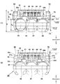
- FIG. 1 It is a bottom view which shows the inside of upper case 31 after attaching latch button 60,70, Comprising: (1) is a figure at the time of non-operation of latch button 60, 70 (normal state), (2) is a latch It is a figure at the time of operation of button 60,70.
- FIG. 1 is a figure at the time of non-operation of latch button 60, 70 (normal state)
- (2) is a latch It is a figure at the time of operation of button 60,70.
- FIG. 7 is a partial view showing the positional relationship between the shape of the circuit board 80 and the latch buttons 60 and 70, wherein (1) is a top view of the circuit board 80, and (2) is a bottom view of the circuit board 80; It is a front view (partly perspective view) which shows arrangement
- FIG. 1 is a side view of a power tool having a battery pack 30 according to an embodiment of the present invention.
- the electric power tool which is one form of electric equipment drives a motor by using a battery pack 30 with a rated voltage of 10.8 V as a power supply, and drives a tip tool and a working device using a rotational driving force of the motor.
- Various types of products are realized for the electric power tool, but the electric power tool main body 1 shown in FIG. 1 is rotated by an end tool such as a bit or socket wrench (not shown) attached to the end tool holding portion 8. It is called an impact tool that performs tightening work by applying a striking force.
- the power tool body 1 includes a housing 2 that forms an outer shape.
- the housing 2 has a cylindrical body 2a containing a motor (not shown) that consumes the power supplied from the battery pack and a power transmission mechanism for transmitting the power of the motor to the end tool holding portion 8, and a body
- a handle portion 2b extending downward in a direction substantially orthogonal to the central axis direction of 2a, and an enlarged diameter portion 2c are formed at the tip of the handle portion 2b.
- a trigger-like operation switch 6 is provided in the vicinity of a portion of the handle portion 2 b that the forefinger strikes when the operator grips.
- a forward / reverse switching lever 7 is provided for switching the rotational direction of the motor in the forward or reverse direction.
- the enlarged diameter portion 2c is a portion formed to have a diameter larger than that of the handle portion 2b for mounting the battery pack 30, and a battery pack mounting portion 10 for mounting the battery pack 30 below the enlarged diameter portion 2c. Is formed.
- the enlarged diameter portion 2c has a certain length in the front-rear direction to hold the battery pack 30, and also has a size corresponding to the lateral width of the upper surface of the battery pack 30 in the lateral direction.
- a rail groove (not shown) engaged with a mounting rail (described later) provided on the battery pack 30 side at the position facing the battery pack 30 in the battery pack mounting portion 10
- the electric device side connection terminal (not shown) for establishing the power path and the signal path of A hammer case 3 accommodating the power transmission mechanism and the rear of the tip tool holding portion 8 is provided in front of the body portion 2a.
- a lithium ion battery with a rated voltage of 3.6 V are accommodated in series.
- Charging of the battery pack 30 is performed by removing it from the power tool main body 1 and attaching it to an external charging device (not shown).
- the battery pack 30 is attached to the power tool main body 1 by sliding the battery pack 30 in the battery pack mounting direction indicated by the arrow, with the rail of the battery pack 30 engaged with the rail groove of the power tool main body 1 Move relative.
- a latch mechanism described later operates to fix the battery pack 30 and the power tool main body 1 so as not to move relative to each other.
- the operator holds the operation parts 62, 72 (72 in FIG. 1 can not be seen in FIG. 1) of the latch button located on both left and right sides. While maintaining, the battery pack 30 is moved in the opposite direction to the mounting direction.
- FIG. 2 is a perspective view of a battery pack 30 according to an embodiment of the present invention.
- the housing of the battery pack 30 is formed by a lower case 51 and an upper case 31 which can be divided in the vertical direction.
- the lower case 51 and the upper case 31 are made of members that do not conduct electricity, for example, made of synthetic resin such as plastic, and are fixed to each other by four screws (not shown) inserted upward from the lower case 51 side.
- the upper part of the upper case 31 is formed with a battery pack mounting mechanism in which rail portions, that is, two rails 38a and 38b are formed for mounting on the battery pack mounting portion 10.
- Rails 38a and 38b are arranged in the same direction as the mounting direction of battery pack 30, and project in the lateral direction from the upper end vicinity of vertical surfaces 37a and 37b extending upward from lower surface 33 of upper case 31. It is formed to When viewed in the longitudinal direction, the front ends of the rails 38a, 38b are open ends, and the rear end is a closed end connected to the front wall of the ridge 36. Rails 38a and 38b are formed in a shape corresponding to a rail groove (not shown) formed in battery pack mounting portion 10 of electric power tool main body 1, and latch 38 is engaged with rail grooves 38a and 38b. By engaging the engaging portion such as the hook 65 (the right hook which can not be seen in FIG.
- the pack 30 is fixed so as not to move in the mounting direction of the power tool body 1.
- the claws 65, 75 moving in conjunction with the latch buttons 60, 70 move inward from the vertical surfaces 37a, 37b. Since the locked state with the locking claw (not shown) formed on the power tool main body 1 side is released, the battery pack 30 is moved in the opposite direction to the mounting direction while the locked state is released. Then, the battery pack 30 can be removed from the power tool main body 1.
- a flat lower surface 33 is formed on the front side of the upper case 31, and a front surface 32 a extending in a substantially vertical direction is formed on the front side from the lower surface 33.
- a right slope 32c and a left slope 32d are formed obliquely downward on the left and right sides of the lower surface 33 facing the outside.
- the front surface 32a (see FIG. 1) is formed to be substantially close to the vertical surface, but the inclination angles of the right slope 32c and the left slope 32d are configured to be large. This shape is because the width W R (see FIG. 8 described later) of the rails 38 a and 38 b is sufficiently smaller than the width W (see FIG. 8 described later) of the battery pack 30.
- An upper surface 35 formed higher than the lower surface 33 is formed on an inner portion of the lower surface 33.
- the boundary between the lower surface 33 and the upper surface 35 in the region sandwiched by the rails 38a and 38b is formed in a step shape, and their connection portion is a step 34 having a vertical surface.
- a plurality of slots 41 to 45 are formed in the slot group disposition area 40 (see FIG. 3 described later) extending from the stepped portion 34 to the front portion of the upper surface 35 and extending rearward from the vertical surface of the stepped portion 34.
- the slots 41 to 45 are notches so as to have a predetermined length in the battery pack mounting direction, and the electric tool main body 1 or an external charging device (see FIG.
- a plurality of connection terminals (described later in FIG. 3) that can be fitted with the device side terminals (not shown) are disposed.
- the slots 41 to 45 are shaped such that a plate-like terminal on the side of the electric power tool body moved along the lower surface 33 side can be inserted.
- the slot 41 on the side closer to the right rail 38a of the battery pack 30 serves as an insertion port for the positive electrode terminal (+ terminal). Further, the slot 45 on the side closer to the rail 38 b on the left side of the battery pack 30 is an insertion port for the negative electrode terminal ( ⁇ terminal).
- the positive electrode side and the negative electrode side of the power terminal for transmitting electric power are disposed sufficiently apart, and the positive electrode terminal is provided on the rightmost side and the negative electrode terminal is provided on the leftmost side.
- a plurality of signal terminals for signal transmission used to control the battery pack 30 and the power tool main body 1 or an external charging device (not shown) are disposed.
- the three slots 42 to 44 are provided between the power terminal groups.
- the slot 42 is an insertion port for a T terminal for outputting a signal serving as identification information of the battery pack 30 to the power tool body or the charging device.
- the slot 43 is an insertion port for a V terminal for receiving a control signal from an external charging device (not shown).
- the slot 44 is an insertion port for an LD terminal for outputting an abnormal stop signal by a battery protection circuit described later included in the battery pack 30.
- a raised portion 36 which is formed to be slightly raised above the upper surface 35.
- the raised portion 36 is formed to secure the movement space of the latch buttons 60 and 70 of the latch mechanism (latch portion) which translates in the left and right direction, and does not interfere with the movement space of the latch buttons 60 and 70.
- a recessed stopper portion 46 is formed in the vicinity of the left and right center of 36.
- the stopper portion 46 serves as an abutting surface against which a projection (not shown) formed on the battery pack attachment portion 10 abuts when the battery pack 30 is attached to the battery pack attachment portion 10.
- a slit 47 serving as a cooling air inlet communicating with the inside of the battery pack 30 is provided.
- the slit 47 is a wind window used to force the cooling air to flow inside the battery pack 30 when the battery pack 30 is connected to a charging device (not shown) to perform charging.
- the cooling air taken into the inside is discharged to the outside from a slit (not shown in FIG. 2), which is a ventilating window provided on the front wall of the lower case 51.
- FIG. 3 is an exploded perspective view of the battery pack 30.
- the battery pack 30 is housed in a housing formed by the upper case 31 and the lower case 51 in a state in which the battery packs 56 to 58 are arranged in the left-right direction so that the longitudinal axes B1 direction is the same. is there.
- the battery cells 56 to 58 are cylindrical so-called "18650 size" cylindrical lithium ion secondary batteries having a diameter of 18 mm and a length of 650 mm.
- the arrangement of the positive electrode and the negative electrode of the adjacent battery cells 56 and 57 and the battery cells 57 and 58 is reversed in the front and rear direction
- the battery cells 56 to 58 are connected in series by connecting adjacent electrodes with a metal plate or the like.
- the battery cells 56 to 58 are fixed by a separator 90 made of a nonconductor such as a synthetic resin.
- the separator 90 holds the battery cell so that only the front and rear sides, which are both ends of the battery cell, are opened, and functions as a base for fixing the circuit board 80 on the top. About half of the separator 90 in the height direction is accommodated in the internal space of the lower case 51.
- the lower case 51 is made of a synthetic resin having an opening on the upper side, and raised portions 53a and 53b are formed on the bottom side so that the battery cells 56 to 57 do not move in the front-rear direction and the left-right direction.
- the purpose of providing the raised portions 53a and 53b is to hold the separator 90 stably so as to prevent the battery cells 56 to 57 and the separator 90 from shaking due to the vibration at the time of use of the electric power tool. Therefore, the outer surface (bottom surface) is formed in a flat shape and the ribs are formed on the inner wall surface even if it is realized by forming a concave formed in a mountain shape from the outer side to the inner side like the lower case 51 of this embodiment.
- Screw bosses 48a to 48d are formed at four places around the upper case 31, and screw holes 54a to 54d (but not seen 54c) can be formed at four places around the lower case 51 Ru.
- the upper case 31 having an opening downward and the lower case 51 having an opening upward are fixed by screws (not shown) by these screws.
- the circuit board 80 is a control unit for fixing the metal connection terminals 81 to 85 for connection to the terminals on the side of the mounted electric apparatus body, monitoring the discharge state and the charge state of the battery cells 56 to 58 (
- the control circuit is mainly used to mount electronic elements and sensors that constitute the control circuit, and to mount a battery voltage check component for displaying the remaining amount of the battery.
- the battery voltage check component is mounted on an elongated surface in the left-right direction on the rear side of the circuit board 80, and includes a push-type switch 87 and a display unit including four light emitting means 88a to 88d.
- LEDs light emitting diodes
- the switch 87 operable from the outside of the battery pack 30 is pressed, the number of light emitting diodes corresponds to the remaining amount of the battery cells 56 to 58. (LED) lights up.
- the switch 87 is operable from the outside of the upper case 31, and a movable piece 39 a which can press the plunger 87 b of the switch 87 is provided above the rear surface 32 b of the upper case 31. Further, through holes 39 b to 39 e are formed in the upper case 31 so that the lighting conditions of the light emitting means 88 a to 88 d can be easily visually recognized from the outside.
- the circuit board 80 is designed to be as small as possible.
- recesses 80d and 80e which are notched parts largely cut inward, are formed.
- the recesses 80 d and 80 e are provided so as not to interfere with the movement range of the latch buttons 60 and 70.
- Two screw holes 80f and 80g are formed in the circuit board 80, and the circuit board 80 is fixed to the screw bosses 93a and 93b of the separator 90 by two screws not shown.
- fixing bases 91a, 91b, 92a, 92b having concave steps are formed on the separator 90 so as to extend upward from the wall surface of the separator 90.
- the fixed bases 91 a, 91 b, 92 a, 92 b are manufactured by integral molding of a synthetic resin together with the separator 90.
- a substantially rectangular front side area is disposed on the front side of the narrow portion sandwiched between the concave portions 80d and 80e of the circuit board 80, and five connection terminals 81 to 85 are disposed in the left-right direction.
- a slot group disposition area 40 is formed in a portion surrounded by a dotted line of the upper surface 35 located on the front side of the raised portion 36. In the battery pack 30 of this embodiment, the front end portion of the slot group disposition area 40 and the front end portions of the rails 38a and 38b do not coincide or approach each other. 38b was configured to extend.
- a through hole 38c is provided in the vicinity of the rear end of the vertical surface 37b holding the rail 38b so that the claw portion 75 of the latch mechanism can protrude outward from the vertical surface 37b of the upper case 31.
- a through hole is formed in the vicinity of the rear end of the vertical surface 37a also on the rail 38a side.
- the latch mechanism includes latch buttons 60 and 70, attachment parts 66 and 76 for fixing the latch buttons 60 and 70 to the inner wall of the upper case 31 so as to be movable within a predetermined range, and latch buttons 60 and 70,
- the upper case 31 is constituted by springs 68 and 78 serving as spring means for urging the case from the inside to the outside, and screws (not shown) for screwing the attachment parts 66 and 76 to the upper case 31.
- the mounting parts 66, 76 form abutment surfaces for the inner ends of the springs 68, 78 and are connected with sliding retaining surfaces 67, 77 having arcuate surfaces 67a, 77a for retaining the springs 68, 78. .
- Screw holes 66a and 76a are formed in the attachment parts 66 and 76, respectively.
- FIG. 4 is a perspective view of the battery pack 30, in which a part of the upper case 31 is omitted to be in a transparent state.
- the corner portions on the left and right sides of the front end of the circuit board 80 are stably held by the fixing bases 91 a and 91 b.
- Five connection terminals 81 to 85 are fixed on the upper side of the circuit board 80.
- the connection terminals 81 to 85 are formed by cutting a flat plate made of a conductive metal by press work and then bending it into a U shape.
- the U-shaped bottom portion is the rear vertical surface, and an arm portion extending from the upper side of the right side surface and the left side wall to the front side is formed.
- connection terminals 81 to 85 are fixed to the circuit board 80 and connected to the wiring pattern.
- the range occupied by the connection terminals 81 to 85 is located inside (left side) of the center axis line B1 (see FIG. 3) of the battery cell 56 located on the right side, and the center axis line B1 of the battery cell 58 located on the left side 3) is located inside (right side).
- connection terminals since the number of connection terminals is reduced from seven to five in the prior art, the distance between the rails 38a and 38b can be narrowed without changing the size of the components of the connection terminals 81 to 85. As a result, the width in the lateral direction required for the arrangement of the latch buttons 60 and 70 can also be reduced.
- the right slope 32c and the left slope 32d of the upper case 31 are formed such that the slopes thereof are along the cylindrical surfaces of the battery cells 56, 57, and therefore, lower from the rail mechanism disposed above the battery cells 56-58.
- the corners of the outer shape to the case 51 can be made smoother than before.
- FIG. 5 is a view of FIG. 4 as viewed from the front side, and (1) shows a normal state where the latch buttons 60 and 70 are not operated.
- rail 38a is disposed in the upper region of battery cell 56 disposed on the right side
- rail 38b is disposed in the upper region of battery cell 58 disposed on the left side.
- the claws 65 and 75 move in the left and right direction in the upper regions of the battery cells 56 and 58 arranged at the left and right ends, and the operation portions 62 and 72 of the latch buttons 60 and 70 are in the upper regions of the battery cells 56 and 58 It moves in the lateral direction outer part more than.
- the latch button 70 protrudes slightly leftward as shown by the arrow 96 from the left end (right end in the figure) of the upper case 31 and the lower case 51 in the normal state where the operator is not operated.
- the lower end position of the latch button 70 protrudes below the upper surface of the separator 90 in the direction of the arrow 98. That is, using the cylindrical surface of the battery cell 58, the left slope 32d is not vertical and is an inclined surface, and the lower end portion of the latch button 70 reaches the space secured by the inclined surface.
- FIG. 5 (2) shows a state in which the latch buttons 60 and 70 are operated.
- the left end position (right end in the figure) of the latch button 70 retracts inward from the left end of the upper case 31 and the lower case 51 as shown by the arrow 99. At this time, the position of the lower end of the latch button 70 approaches the battery cell 58.
- the thickness 13 in the vertical direction of the rails 38a and 38b is formed to be the same as the thickness 14 in the left-right direction of the vertical surfaces 37a and 37b. In the conventional battery pack, the strength of the rails is secured by making the thickness 13 thicker than the thickness 14.
- the rails 38a and 38b are accommodated in a relatively long front-rear length. Since the number of battery cells is reduced, the thickness 13 can be thinner than in the conventional case, which makes it possible to slightly lower the height H of the battery pack.
- the upper position of the raised portion 36 can be made lower than in the prior art.
- the protrusion 36 is provided to secure the movement space of the latch buttons 60 and 70, but the difference between the upper end surface of the upper surface 35 and the upper end of the protrusion 36 is only the arrow 97 here.
- the height H B of the battery cells 56-58 are 18 mm
- vertical width of the latch buttons 60 and 70 i.e. the height H L occupied by the operating unit 62, 72 is 15.5 mm.
- the battery pack The height H of 30 could be configured as low as 38 mm.
- the battery cells are arranged in the direction crossing the rails 38a and 38b, that is, in the left-right direction. Therefore, the vertical position where the latch buttons 60 and 70 are provided can not vertically overlap the height H L and the height H B above the upper end position of the battery cell, that is, in FIG. In that case, the height H 'of the battery pack is at least 41 mm, which is larger than that of this embodiment.
- FIG. 6 is a view for explaining the positional relationship between the latch buttons 60 and 70 and the battery cells 56 to 58 in the left and right and up and down directions, which corresponds to a view from the rear side of the battery pack 30.
- FIG. 6 (1) shows the non-operation (normal state) of the latch buttons 60, 70, and (2) shows the operation of the latch buttons 60, 70.
- the operating portions 62, 72 of the latch buttons 60, 70 extend downward from the upper side of the battery cells 56 to 58 in the vertical direction to the side of the battery cells 56, 58, and from the left and right
- a part of the lower side of the operation parts 62 and 72 is arranged to overlap the battery cells 56 and 58.
- the battery cells 56 to 58 and the separator 90 are arranged so that the operation parts 62 and 72 reach below the upper surface position, so that a cylindrical battery is provided under the latch buttons 60 and 70.
- Arc surfaces 61a and 71a curved along the outer peripheral surfaces of the cells 56 and 58 are formed.
- the arc surfaces 61 a and 71 a are also avoiding portions for avoiding contact with the outer peripheral surfaces of the battery cells 56 and 58.
- FIG. 6 (1) when the latch buttons 60 and 70 are not operated, there is a gap between the separator 90 and the outer surface.
- the latch button 60 approaches the vertical virtual plane A1 of the left and right center of the battery pack 30.
- the arc surface 61a abuts on the outer surface of the separator 90, or approaches even if it does not abut on.
- the movement on the latch button 70 side is the same, and the latch button 70 approaches the vertical virtual plane A1 at the center of the battery pack 30 at the left and right.
- the battery cells 56 to 58 are not placed horizontally as in the prior art (the axial direction is left and right), but are placed vertically (the axis B1 is front and back) and viewed in the vertical direction. Since the vertical positions occupied by 56 to 58 and the latch buttons 60 and 70 are overlapped, the size of the battery pack 30, particularly in the height direction, is made compact while maintaining the operability of the latch mechanism equal to that of the conventional battery pack. It could be configured.
- FIG. 7 is a view showing the shape of the latch button 60, 70 alone, (1) is a bottom view, (2) is a front view, (3) is a top view, and (4) is a side view.
- the latch buttons 60 and 70 have symmetrical shapes, and one end of the springs 68 and 78 is in contact with the side closer than the left and right center (vertical plane A1 in FIG. 6).
- Recesses 61 and 71 for contact are formed, and operation portions 62 and 72 for the operator to hold with fingers are formed at portions farther than the left and right center.
- Guide surfaces 63, 73 are formed on the rear side of the latch buttons 60, 70 so that they can slide smoothly along the inner wall surface of the upper case 31.
- the guide surfaces 63, 73 are formed with vertical ribs 63a, 73a projecting rearward, and by engaging with recesses (not shown) formed in the inner wall surface of the upper case 31, the latch buttons 60, 70 are formed. Guide the slide.
- the connection arms 64 and 74 extend forward from the front sides of the latch buttons 60 and 70, and claws 65 and 75 are formed extending in the lateral direction from the vicinity of the front ends of the connection arms 64 and 74.
- the connecting arms 64, 74 are formed by arm portions 64a, 74a and horizontal ribs 64b, 74b extending inward in the horizontal direction.
- the horizontal ribs 64 b and 74 b are disposed between the upper surface of the circuit board 80 and the inner wall surface of the upper case 31, and function as a reinforcing portion for suppressing the deformation of the connecting arm 64.
- the latch buttons 60 and 70 are brought into sliding contact with the inner wall surface of the upper case 31 while the guide surfaces 63 and 73, the vertical ribs 63a and 73a, and the portions facing the front side via the recesses 61 and 71 contact the inner wall surface of the upper case 31. It is possible to stabilize the posture when sliding.
- the claws 65 and 75 are hooked in a top view together with the connecting arms 64 and 74, and the rear surfaces 65a and 75a of the claws 65 and 75 are on the electric power tool main body 1 side or an electric equipment main body or outside not shown. It becomes an abutment surface that is hooked to the claws, recesses, holes and the like of the charger.
- FIG. 7 (2) is a front view of the latch button 60, 70 alone.
- the latch buttons 60 and 70 are manufactured by integral molding of a synthetic resin such as plastic, and are formed by connecting claws 65 and 75 moving together with the main body to the main body functioning as a push button.
- arc portions 61a and 71a are formed along the outer peripheral cylindrical surfaces of the battery cells 56 and 58 disposed on the left and right sides.
- the vertical rib positions of the horizontal ribs 64b and 74b are disposed on the upper side, and the circuit board 80 is positioned below the horizontal ribs 64b and 74b.
- FIG. 7C is a top view of the latch button 60, 70 alone.
- the upper side of the latch button 60, 70 and near the outer end of the spring 68, 78 is formed so that the upper wall surface 61b, 71b covers the vicinity of the end of the spring 68, 78.
- FIG. 7 (4) is a side view of the latch button 70.
- the side view of the operation portion 72 of the latch button 70 is not a complete rectangular shape, but is shaped such that a corner portion 71c in a portion close to the rail 38b is obliquely cut off. This is to conform to the shape of the upper case 31 from the upper surface 35 of the battery pack 30 to the raised portion 36.
- FIG. 8 is a bottom view showing the inner wall portion of the upper case 31 after attaching the latch buttons 60 and 70, wherein (1) is when the latch buttons 60 and 70 are not operated (normal state), (2) Is when the latch button 60, 70 is operated.
- the length L R in the front-rear direction of the rails 38 a, 38 b occupies the length of the upper case 31, that is, about half the length L of the battery pack 30.
- the width of the rails 38a and 38b is made relatively smaller than the width W of the battery pack 30 in the left-right direction, so that the width W R is smaller and a compact rail mechanism is obtained.
- the distance between the rail grooves on the side of the electric power tool main body 1 can be narrowed, and as a result, the battery pack mounting portion 10 can be formed compactly.
- the size below the handle portion 2b could be reduced.
- the latch buttons 60 and 70 can move smoothly in the left-right direction.
- FIG. 8 (2) when the operator grips the latch buttons 60, 70 and pushes both of them against the biasing force of the springs 68, 78, they are fixed by the connecting arms 64, 74.
- the claws 65 and 75 also move in parallel in conjunction with each other.
- a cantilevered movable piece 39a is formed so that the plunger 87b (see FIG. 9 described later) of the switch 87 can be pressed from the outer surface of the upper case 31.
- the movable piece 39a is obtained by cutting out a part of the upper case 31 and connecting a convex member protruding from the outer surface of the case to the upper case 31 with a thin support arm, but these are manufactured integrally with the upper case 31 Ru.
- the through holes 39b to 39e are rectangular cutouts in top view, and light from the light emitting means 88a to 88d reaches the outside through the through holes 39b to 39e.
- the outer surface (the outer surface of the upper case 31) of the movable piece 39a and the through holes 39b to 39e is covered with a film having a flexible transparent window.
- FIG. 9 is a partial view showing the shape of the circuit board 80 and the positional relationship between the latch buttons 60 and 70, wherein (1) is a top view of the circuit board 80 and (2) is a bottom view of the circuit board 80. is there.
- the position of the latch mechanism in the normal state not operated in addition to the circuit board 80 is also shown.
- the shape of the circuit board 80 as shown in FIG. 3, five connection terminals 81 to 85 are disposed in the rectangular front side area 80a, and battery voltage check components are provided in the left and right rear side area 80c. That is, a push switch 87 and four light emitting means 88a to 88d are provided.
- the switch 87 is a push switch in which a cylindrical plunger 87 b protrudes upward from the main body portion 87 a and is ON only when pressed. Between the front side area 80a and the rear side area 80c, recessed portions 80d and 80e which are cut out in the left and right direction are formed. The recessed portions 80 d and 80 e are configured not to interfere with the sliding space in the left and right direction of the latch buttons 60 and 70.
- the connection region (narrow portion) 80b which is a region sandwiched between the concave portions 80d and 80e and which connects the front side region 80a and the rear side region 80c and which has a narrow width in the left-right direction, as shown in FIG.
- the microcomputer 95 is mounted.
- the microcomputer 95 is an integrated circuit in which a CPU (central processing unit), a memory, and the like are integrated in a small chip, which is enclosed in a resin package and has a plurality of terminals.
- connection terminals 81 and 85 are used for the power supply of the rated voltage 10.8V among the front side area
- the wiring pattern for power transmission to the connection terminals 81 and 85 is disposed in the front side area 80a. Also, a wiring pattern is provided for transmitting control signals to an external device (power tool body 1, electric device main body not shown, external charger not shown, etc.) to which battery pack 30 is connected via connection terminals 82 to 84.
- an external device power tool body 1, electric device main body not shown, external charger not shown, etc.
- a battery voltage check component requiring electric power for lighting is mounted in the rear side area 80c.
- the microcomputer 95 for monitoring and controlling the voltage of the battery cells in the battery pack 30 and controlling the lighting of the light emitting means 88a to 88d is disposed in the connection area 80b.
- the microcomputer 95 in the connecting area 80b By arranging the microcomputer 95 in the connecting area 80b in this manner, the wiring to the front side area 80a and the wiring to the rear side area 80c are short, which is efficient.
- the movement and attachment space of the latch buttons 60 and 70 can be secured, and the attachment parts of the latch buttons 60 and 70 in the area of the recessed portions 80d and 80e. 66, 76 can be arranged.
- FIG. 10 is a front view (partially transparent view) showing the arrangement of battery cells of a battery pack 130 according to a modification of the present embodiment, and (1) shows the arrangement when 21700 size battery cells are used.
- the arrangement positions in the case of accommodating three 21700 size battery cells 156 to 157 in the lateral direction are illustrated.
- the shape of the upper case changes the inclination of the right slope 32c and the left slope 32d, and further shifts the position of the rear surface 32b to the rear side.
- the battery pack for the 21700 size can be realized using the mechanism, the latch mechanism, and the circuit board 80 as they are.
- the shape of the latch buttons 60 and 70 may be slightly changed to increase the amount of protrusion in the left-right direction, but the positions of the rails 38a and 38b, the positions of the connection terminals 81 to 85, the slot group disposition area 40 If the shape of FIG. 3 is the same as the embodiment shown in FIG. 2 to FIG. 9, it is compatible with the battery pack 30 using 18650 size battery cells, and a large capacity battery pack 130 is easily realized. it can.
- FIG. 10 (2) shows the arrangement of the battery pack 230 when six batteries 56B to 58B are used in addition to the battery cells 56A to 58A.
- the separator 190 is configured to hold the battery cell in two stages, upper and lower.
- the upper case is not shown in FIG. 10 (2), the upper case 31 can be the same as the embodiment shown in FIGS. 2 to 9, and only the lower case can accommodate the separator 190. It should be about the size of the degree.
- Three battery cells 256 to 258 are connected in series to form a first cell unit, and three battery cells 259 to 261 are connected in series to form a second cell unit, and the first cell unit By connecting the second cell units in parallel, a battery pack with a rated voltage of 10.8 V is obtained.
- the number of battery cells to be used is arbitrary, and if the battery pack arranges the battery cells so that the axis lines of the cylindrical battery cells are in the front-rear direction, the size is easy to use using the outer surfaces of the battery cells at both left and right
- the latch buttons can be arranged to overlap vertically. Also, if the lateral position of the rail is also disposed inside the center position of the battery cells at both left and right ends, a battery pack with a compact rail mechanism can be realized.
- SYMBOLS 1 Electric tool main body, 2 ... Housing, 2a ... Torso part, 2b ... Handle part, 2c ... Expansion diameter part, 3 ... Hammer case, 6 ... Operation switch, 7 ... Forward / reverse switching lever, 8 ... Tip tool holding part, DESCRIPTION OF SYMBOLS 10 battery pack attachment part 30 battery pack 31 upper case 31b opening hole 32a front surface 32b rear surface 32c right slope 32d left slope 33 lower surface 34 step portion 35: upper surface, 36: raised portion, 37a, 37b: vertical surface, 38a, 38b: rail, 38c: through hole, 39a: movable piece, 39b to 39e: through hole, 40: slot group arrangement area, 41 to 45 ...
- Back side Area 80d, 80e: recessed portion, 80f, 80g: screw hole, 81 to 85: connection terminal, 87: switch, 87a: body portion, 87b: plunger, 88a to 88d: light emitting means, 90: separator, 91a, 91 b, 92a, 92b: fixed base, 93a, 93b: screw boss, 95: microcomputer, 130: battery pack, 156: battery cell, 190: separator, 230: battery pack, 256 to 261: battery cell, A1: vertical surface (Virtual surface), B1 ... (battery cell) axis, W ... battery pack width, W R ... rail width
Landscapes
- Chemical & Material Sciences (AREA)
- Chemical Kinetics & Catalysis (AREA)
- Electrochemistry (AREA)
- General Chemical & Material Sciences (AREA)
- Engineering & Computer Science (AREA)
- Life Sciences & Earth Sciences (AREA)
- Biophysics (AREA)
- Computer Hardware Design (AREA)
- Manufacturing & Machinery (AREA)
- Mechanical Engineering (AREA)
- Battery Mounting, Suspending (AREA)
Abstract
レール方向に対する電池セルの配置方向を変更することによって、左右両側に設けられるラッチ機構を効率良く配置した電池パックを提供する。上ケースには前後方向に2本の平行なレール38a、38bが設けられ、電気機器本体に形成されるレール溝に案内されることにより着脱される電池パック30であって、スライド方向と電池セル56~58の長手軸が一致するようにケース内に電池セルを収容する。上ケース31の左右両側にはスライド方向と交差する方向に移動する2つのラッチボタン60、70を備える。ラッチボタン60、70の操作部62、72の占める高さHLは、電池セル56~58の占める高さHBと上下方向に占める位置が部分的にオーバーラップするようにして、操作部62、72の大きさを従来と同様にしながら全体高さHを抑えたコンパクトな電池パックを実現した。
Description
本発明はモータ、照明等の負荷装置を備えた電気機器本体に対して電源を供給する電池パックに関するものである。また、電池パックを装着することにより作業機器を作動させる電池パックを用いた電気機器に関するものである。
商用電源を用いる電気機器が、リチウムイオン電池等の二次電池を用いた電池パックにて駆動されるようになり、電気機器のコードレス化が進んでいる。例えば、モータにより先端工具を駆動する手持ち式の電動工具においては、複数の二次電池セルを収容した電池パックが電源として用いられ、電池パックに蓄電された電気エネルギーにてモータ等の負荷装置を駆動する。電池パックは電動工具本体に着脱可能に構成され、電池パックは放電によって電圧が低下したら電動工具本体から取り外されて、外部充電器を用いて充電される。このような電池パックの例として特許文献1の技術が知られている。特許文献1の電池パックでは、定格電圧3.6Vのリチウムイオン二次電池のセルを4本直列に接続し、それらを二組準備して並列接続することにより定格電圧14.4Vの電池パックを実現している。電池パックの上ケースの左右両側には、電池パックの装着方向に向けて平行に延びる2本のレール部が設けられ、レール部の後方側の左右には電池パックが電動工具から脱落しないように保持するラッチ機構が設けられる。
コードレス型の電気機器においては所定の稼働時間の確保や、所定の出力が要求され、二次電池の性能向上に伴い高電圧化や高出力化が図られてきた。一方で、高い出力よりもコンパクトで軽量な電気機器の電源用途の要求も高まっている。コンパクトで軽量な電気機器では、定格電圧7.2Vや10.8V程度で動作するため、二次電池としてリチウム電池のセルを用いる場合は、18650サイズ等の電池セルを2本又は3本直列接続すれば良い。電位セルを3本収容する電池パックを実現する際には、電池セルをどのように配置するかが問題になる。出願人による従来の10.8Vの電池パックでは、特許文献2に示すように2本の電池セルを水平方向に配置し、1本を鉛直方向に配置するようにし、電動工具の下方から上方に、即ち鉛直方向に電池パックを移動して電動工具に装着するようにしていた。この際、鉛直方向に配置される電池セルの収容部分を電池パックの装着をガイドするためのガイド部として利用していた。しかしながら、電動工具の小型・軽量化の要求に伴い、特許文献2のような電池パックを更に小型化したいという要望があった。
本発明は上記背景に鑑みてなされたもので、その目的は、電池パックの電池セル及びラッチ部の配置を工夫して寸法を抑えてコンパクトな形状とした電池パック及びその電池パックを用いた電気機器を提供することにある。
本発明の他の目的は、レール方向に対する電池セルの配置方向を変更することによって、左右両側に設けられるラッチ機構を効率良く配置した電池パック及びそれを用いた電気機器を提供することにある。
本発明のさらに他の目的は、電池パック内に収容される回路基板の形状を改良して実装効率を向上させた電池パック及びそれを用いた電気機器を提供することにある。
本発明の他の目的は、レール方向に対する電池セルの配置方向を変更することによって、左右両側に設けられるラッチ機構を効率良く配置した電池パック及びそれを用いた電気機器を提供することにある。
本発明のさらに他の目的は、電池パック内に収容される回路基板の形状を改良して実装効率を向上させた電池パック及びそれを用いた電気機器を提供することにある。
本願において開示される発明のうち代表的な特徴を説明すれば次のとおりである。
本発明の一つの特徴によれば、上ケースと下ケースによって構成されるハウジングを有し、ハウジングには前後方向に2本の略平行なレール部が設けられ、電気機器本体に形成されるレール溝に案内されることにより電気機器本体に対して前後方向にスライドして着脱される電池パックにおいて、長手軸が前後方向と一致するようにハウジング内に並べて収容される複数の円柱状の電池セルと、ハウジングの左右両側に配置される2つのラッチ部とを備え、ラッチ部はそれぞれ、電気機器本体に形成される係合部に係合する爪部と、爪部を操作するよう前後方向と交差する左右方向に移動する操作部を備える。ラッチ部の爪部は、上下方向において電池セルより上側に位置し、操作部は上下方向において電池セルの上側から電池セルの側方に亘って延びるように形成される。ラッチ部を左右方向からみた際には、その操作部の一部は電池セルと重なるように位置するように配置される。つまり、電池セルと操作部の上下方向における位置が部分的に重なることになる。また、操作部は操作された状態においてハウジングの左右両端位置から左右方向外側に突出しないように配置される。
本発明の一つの特徴によれば、上ケースと下ケースによって構成されるハウジングを有し、ハウジングには前後方向に2本の略平行なレール部が設けられ、電気機器本体に形成されるレール溝に案内されることにより電気機器本体に対して前後方向にスライドして着脱される電池パックにおいて、長手軸が前後方向と一致するようにハウジング内に並べて収容される複数の円柱状の電池セルと、ハウジングの左右両側に配置される2つのラッチ部とを備え、ラッチ部はそれぞれ、電気機器本体に形成される係合部に係合する爪部と、爪部を操作するよう前後方向と交差する左右方向に移動する操作部を備える。ラッチ部の爪部は、上下方向において電池セルより上側に位置し、操作部は上下方向において電池セルの上側から電池セルの側方に亘って延びるように形成される。ラッチ部を左右方向からみた際には、その操作部の一部は電池セルと重なるように位置するように配置される。つまり、電池セルと操作部の上下方向における位置が部分的に重なることになる。また、操作部は操作された状態においてハウジングの左右両端位置から左右方向外側に突出しないように配置される。
本発明の他の特徴によれば、レール部は左右両端に配置される電池セルの上側領域内に配置され、爪部は左右両端に配置される電池セルの上側領域内で左右方向に移動し、操作部は上側領域よりも左右方向外側部分にて移動するように構成される。また、操作部はバネ手段によって左右方向外側に向けて付勢され、レール部の近傍に設けられる爪部はバネ手段によってハウジングの開口から外側に突出する。操作部が作業者によってバネ手段の付勢力に抗して押されている状態では、爪部は下側に位置する電池セルの径方向中心より内側にまで移動可能とされる。操作部の下側部分には電池セルの外周面を避けた回避部が形成される。
本発明のさらに他の特徴によれば、電池セルは合成樹脂製のセパレータによって固定され、セパレータの上側には制御回路を搭載する回路基板が固定され、回路基板は左右両端に配置される電池セルの左右中心位置よりも内側部分に配置される。回路基板は電子素子やセンサー等を搭載するものであって、前後方向にみてラッチ部の前方側から後方側にまで延び、ラッチ部の可動範囲を避けるように左右両側に切り欠き部を設けることによって、回路基板とラッチ部を上下方向に重なるように配置される。また、回路基板の切り欠き部を設けた幅狭部よりも前側部分に、電気機器本体の端子に接続される複数の接続端子が固定され、幅狭部に電池セルの負荷状態を監視するマイコンを配置し、幅狭部よりも後側部分に電池電圧の表示部を設けた。接続端子の数は例えば5つであって、左右に配置されるレール部に挟まれる領域内に配置すると良い。
本発明によれば、電池パックの電池セル及びラッチ部の配置を工夫して寸法を抑えてコンパクトな形状とした電池パック及びその電池パックを用いた電気機器を提供することができる。
本発明によれば、レール方向に対する電池セルの配置方向を変更することによって、左右両側に設けられるラッチ機構を効率良く配置した電池パック及びそれを用いた電気機器を提供することができる。
本発明によれば、電池パック内に収容される回路基板の形状を改良して実装効率を向上させた電池パック及びそれを用いた電気機器を提供することができる。
本発明によれば、少ない本数の電池セルにて電池パックを構成し、電池セルの向きをレール部と同じ向きにすると共に、電池セルの円柱面の傾斜を利用してその左右2箇所部分にラッチボタンの操作部を配置したので、小型でありながら安定して電気機器本体に保持可能な電池パックを実現できる。
本発明によれば、ラッチ機構の操作部が、上下方向に見て電池セルと重なる(オーバーラップ)するように構成したので、ラッチ機構の操作性を従来の電池パックと同等に保ちながら、電池パックの高さを小さくすることができる。
以下、本発明の実施例を図面に基づいて説明する。以下の図において、同一の部分には同一の符号を付し、繰り返しの説明は省略する。本明細書においては、電気機器の一例として電池パックにて動作する電動工具を用いて説明するものとする。電動工具本体側の前後左右の方向は図1に示す方向とし、電池パックの単体で見た際の前後左右、上下の方向は、図2に示す方向であるとして説明する。尚、電池パックの装着方向は、説明の都合上、電動工具本体側を動かさずに電池パック側を移動させる状況を基準とした方向として説明するが、どちら側を移動しても良いことは言うまでも無い。
図1は本発明の実施例に係る電池パック30を有する電動工具の側面図である。電気機器の一形態である電動工具は、定格電圧10.8Vの電池パック30を電源としてモータを駆動し、モータの回転駆動力を用いて先端工具や作業機器を駆動する。電動工具は種々の種類の製品が実現されているが、図1で示す電動工具本体1は先端工具保持部8に装着される図示しないビットやソケットレンチ等の先端工具に回転力や軸方向の打撃力を加えることにより締め付け作業を行うインパクト工具と呼ばれるものである。電動工具本体1は、外形を形成するハウジング2を備える。ハウジング2には、電池パックから供給される電力を消費するモータ(図示せず)とモータの動力を先端工具保持部8に伝達する動力伝達機構を収容する円筒状の胴体部2aと、胴体部2aの中心軸方向から略直交方向下方に延在するハンドル部2bと、ハンドル部2bの先端に拡径部2cが形成される。ハンドル部2bの一部であって作業者が把持した際に人差し指があたる付近には、トリガ状の動作スイッチ6が設けられる。動作スイッチ6の上方には、モータの回転方向を正方向又は逆方向に切り換えるための正逆切替えレバー7が設けられる。拡径部2cは、電池パック30を装着する為にハンドル部2bよりも径を大きく形成した部分であって、拡径部2cの下方には電池パック30を装着するための電池パック装着部10が形成される。拡径部2cは電池パック30を保持するために前後方向にある程度の長さを有し、左右方向に対しても電池パック30の上面の左右方向幅に対応した程度の大きさを有する。電池パック装着部10であって、電池パック30と対向する位置には、電池パック30側に設けられる装着用のレール(後述)と係合するレール溝(図示せず)と電池パック30側からの電力経路や信号経路を確立するための電気機器側接続端子(図示せず)が形成される。胴体部2aの前方には動力伝達機構を収容するとともに先端工具保持部8の後部を収容するハンマケース3が設けられる。
電池パック30の内部には、定格電圧3.6Vのリチウムイオン電池のセル3本が直列接続された状態で収容される。電池パック30の充電は、電動工具本体1から取り外し、外部充電装置(図示せず)に装着して行なわれる。電池パック30の電動工具本体1に対する装着は、電池パック30のレールを、電動工具本体1のレール溝に係合させた状態にて、矢印に示す電池パック装着方向に電池パック30をスライドさせて相対移動させる。電池パック30が電動工具本体1の規定位置まで移動されると、後述するラッチ機構が動作して電池パック30と電動工具本体1が相対移動しないように固定される。電池パック30を電動工具本体1から取り外すには、作業者は左右両側に位置するラッチボタンの操作部62、72(図1では72は見えない)を挟むようにして内側に押し込み、その押し込んだ状態を維持しながら、電池パック30を装着方向と反対向きに移動させる。
図2は本発明の実施例に係る電池パック30の斜視図である。電池パック30の筐体は、上下方向に分割可能な下ケース51と上ケース31により形成される。下ケース51と上ケース31は電気を通さない部材、例えばプラスチック等の合成樹脂製とし、下ケース51側から上側に向けて挿入される4本の図示しないネジによってお互いが固定される。上ケース31の上側部分には、電池パック装着部10に取り付けるためにレール部、即ち2本のレール38a、38bが形成された電池パックの装着機構が形成される。レール38a、38bは、それらの長手方向が電池パック30の装着方向と同方向に配置され、上ケース31の下段面33から上側に延在する鉛直面37a、37bの上端付近から左右方向に突出するように形成される。長手方向に見てレール38a、38bの前方側端部は開放端となり、後方側の端部は隆起部36の前側壁面と接続された閉鎖端となる。レール38a、38bは、電動工具本体1の電池パック装着部10に形成されたレール溝(図示せず)と対応した形状に形成され、レール38a、38bがレール溝と嵌合した状態で、ラッチの爪となる爪部65(右側の係止部であり図2では見えない)、75が電動工具本体1側の係止爪(図示せず)等の係合部と係合することにより電池パック30が電動工具本体1の装着方向に移動できないように固定される。作業者が左右両側にあるラッチボタン60、70の操作部62、72を押と、ラッチボタン60、70に連動して移動する爪部65、75が鉛直面37a、37bよりも内側に移動して電動工具本体1側に形成された係止爪(図示せず)との係止状態が解除されるので、その係止状態が解除されたまま電池パック30を装着方向と反対側に移動させれば電池パック30を電動工具本体1から取り外すことができる。
上ケース31の前方側には平らな下段面33が形成され、下段面33から前側には略鉛直方向に延びる前面32aが形成される。下段面33から外側に向かう左右両側には、斜め下方に向かう右斜面32cと左斜面32dが形成される。前面32a(図1参照)はほぼ鉛直面に近いように形成されるが、右斜面32cと左斜面32dの傾斜角は大きめに構成される。この形状は、レール38a、38bの左右方向の幅WR(後述する図8参照)が電池パック30の幅W(後述する図8参照)よりも十分狭く構成したためである。下段面33の内側部分には下段面33よりも高く形成された上段面35が形成される。レール38a、38bに挟まれる領域における下段面33と上段面35の境界は階段状に形成され、それらの接続部分は鉛直面を有する段差部34となっている。段差部34から上段面35の前方部分に渡ってスロット群配置領域40(後述する図3参照)になり、段差部34の鉛直面から後方側に延びる複数のスロット41~45が形成される。スロット41~45は電池パック装着方向に所定の長さを有するように切り欠かれた部分であって、この切り欠かれた部分から内側部分には、電動工具本体1又は外部の充電装置(図示せず)の機器側端子と嵌合可能な複数の接続端子(図3にて後述)が配設される。スロット41~45は下段面33側に沿って移動される電動工具本体側の板状のターミナルが、挿入可能なような形状とされる。
スロット41~45は、電池パック30の右側のレール38aに近い側のスロット41が正極端子(+端子)の挿入口となる。また、電池パック30の左側のレール38bに近い側のスロット45が負極端子(-端子)の挿入口となる。電池パック30では通常、電力を伝達するための電力端子の正極側と負極側を十分離すようにして配置するもので、一番右側に正極端子を設けて、一番左側に負極端子を設ける。正極端子と負極端子の間には、電池パック30と電動工具本体1や外部の充電装置(図示せず)への制御に用いる信号伝達用の複数の信号端子が配置され、ここでは信号端子用の3つのスロット42~44が電力端子群の間に設けられる。スロット42は電池パック30の識別情報となる信号を電動工具本体又は充電装置に出力するためのT端子用の挿入口である。スロット43は外部の充電装置(図示せず)からの制御信号が入力されるためのV端子用の挿入口である。スロット44は電池パック30内に含まれる後述する電池保護回路による異常停止信号を出力するLD端子用の挿入口である。
上段面35の後方側には、上段面35よりもわずかに上側に隆起するように形成された隆起部36が形成される。隆起部36は、左右方向に平行移動するラッチ機構(ラッチ部)のラッチボタン60、70の移動空間をその内部に確保するために形成され、ラッチボタン60、70の移動空間と干渉しない隆起部36の左右中央付近には、窪み状とされたストッパ部46が形成される。ストッパ部46は、電池パック30を、電池パック装着部10に装着した際に、電池パック装着部10に形成された突起部(図示せず)が突き当たる突き当て面となるもので、突起部がストッパ部46に当接するまで電池パック30が電動工具本体1に挿入されると、電動工具本体1に配設された複数の端子(機器側端子)と電池パック30に配設された複数の接続端子(図3にて後述)が良好に接触して導通状態となる。また、電池パック30のラッチ機構が作用して、電池パック30が脱落しないようにロックする。ストッパ部46の内側には、電池パック30の内部とつながる冷却風取入口たるスリット47が設けられる。スリット47は、電池パック30を図示せぬ充電装置に連結して充電を行う際に、電池パック30の内部に冷却用の空気を強制的に流すために用いられる風窓であって、電池パック30内に取り込まれた冷却風は下ケース51の前方壁に設けられた排気用の風窓たるスリット(図2では図示していない)から外部に排出される。
図3は電池パック30の分解斜視図である。電池パック30は3本の電池セル56~58の長手軸B1方向が同じ方向となるように左右方向に並べた状態で、上ケース31と下ケース51によって構成されるハウジング内に収容したものである。電池セル56~58は直径18mm、長さ650mmのいわゆる“18650サイズ”と呼ばれる円柱形のリチウムイオン2次電池である。ここでは電極の形状や隣接する電極との接続用の接続タブの図示を省略しているが、隣接する電池セル56と57、電池セル57と58は正極と負極の配置が前後方向に逆になるようにして、隣接する電極間を金属プレート等で接続することによって、電池セル56~58を直列接続する。電池セル56~58は、合成樹脂等の不導体で構成されたセパレータ90にて固定される。セパレータ90は電池セルの両端部となる前後両側だけが開口するようにして電池セルを保持すると共に、上部に回路基板80を固定するための基台として機能する。セパレータ90は、高さ方向の略半分程度が下ケース51の内部空間に収容される。
下ケース51は上側に開口面を有する合成樹脂製であって、電池セル56~57が前後方向及び左右方向に移動しないように、底面側には隆起部53a、53bが形成される。隆起部53a、53bを設ける目的は、セパレータ90を安定的に保持して電動工具の使用時の振動によって電池セル56~57やセパレータ90ががたつかないように保持するためである。従って、本実施例の下ケース51のような底面外側から内側に山状に形成された窪みを形成することにより実現しても、外面(底面)はフラットな形状で構成して内壁面にリブ状の部材を設けるようにして形成しても良い。上ケース31の周囲の4箇所にはネジボス48a~48d(但し48cは見えない)が形成され、下ケース51の周囲の4箇所にはネジ穴54a~54d(但し54cは見えない)が形成される。これらネジによって下向きに開口を有する上ケース31と上向きに開口を有する下ケース51が図示しないネジによって固定される。
回路基板80は、装着される電気機器本体側の端子と接続するための金属製の接続端子81~85を固定するためと、電池セル56~58の放電状態及び充電状態を監視する制御部(制御回路)を構成する電子素子やセンサーを搭載するためと、電池の残量表示のための電池電圧チェック部品を搭載するために主に用いられる。電池電圧チェック部品は、回路基板80の後方の左右方向に細長い面に搭載されるもので、プッシュ式のスイッチ87と、4つの発光手段88a~88dからなる表示部で構成される。ここでは発光手段88a~88dとして発光ダイオード(LED)が用いられ、電池パック30の外側から操作可能とされるスイッチ87が押下されたら、電池セル56~58の残量に応じた数の発光ダイオード(LED)が点灯する。これらの点灯は、制御部に含まれる後述するマイコンによって制御される。スイッチ87は上ケース31の外部から操作可能であり、上ケース31の後面32bの上方には、スイッチ87のプランジャ87bを押圧可能とする可動片39aが設けられる。また、発光手段88a~88dの点灯状況を外部から容易に視認できるようにするための貫通穴39b~39eが上ケース31に形成される。
電池パック30の小型・軽量化のために、回路基板80はできるだけ小さく設計される。回路基板80の中央付近の左右両側には、大きく内側に切り欠いた切り欠き部たる凹部80d、80eが形成される。凹部80d、80eを設けたのは、ラッチボタン60、70の移動範囲と干渉しないようにするためである。回路基板80には2つのネジ穴80f、80g(但し80fは図3では見えない)が形成され、図示しない2本のネジによって回路基板80はセパレータ90のネジボス93a、93bに固定される。セパレータ90には、さらに回路基板80の一部を安定的に固定するために、セパレータ90の壁面から上方に延びて、凹状の段差部を有する固定基台91a、91b、92a、92bが形成される。固定基台91a、91b、92a、92bはセパレータ90とともに合成樹脂の一体成形で製造される。回路基板80の凹部80d、80eに挟まれた幅狭部の前方側には、略長方形の前方側領域が配置され、左右方向に5つの接続端子81~85が配置される。
上ケース31の左斜面32dから隆起部36の左側側面にかけて、ラッチボタン70が貫通するための大きな開口穴31bが形成される。同様にして上ケース31の右斜面32cから隆起部36の右側側面にかけて、ラッチボタン60が貫通するための大きな開口穴(図では見えない)が形成される。隆起部36の前方側に位置する上段面35の点線で囲む部分にはスロット群配置領域40が形成される。本実施例の電池パック30ではスロット群配置領域40の前端部分と、レール38a、38bの前端部分を一致又は近接させるのでは無く、スロット群配置領域40の前端部分から前方側に大きくレール38a、38bが延在するように構成した。このようにレール38a、38bの長さを長くすることによって、18650サイズの電池セルを3本だけ収容するという小型の電池パック30でありながら、レール部分の有効長を大きくすることが可能となり、電池パック30の装着安定性を向上できる。レール38bを保持する鉛直面37bの後端付近には、ラッチ機構の爪部75が上ケース31の鉛直面37bより外側に突出することができるように貫通穴38cが設けられる。同様にしてレール38a側にも、鉛直面37aの後端付近に貫通穴が形成される。
ラッチ機構は、ラッチボタン60、70と、ラッチボタン60、70を所定範囲内で移動できるようにして上ケース31の内壁に固定する為の取付部品66、76と、ラッチボタン60、70を、上ケース31の内側から外側方向に付勢するためのバネ手段たるスプリング68、78と、取付部品66、76を上ケース31にネジ止めするための図示しないネジによって構成される。ラッチ機構を上ケース31の内側に固定し、電池セル56~58を収容して回路基板80を固定したセパレータ90を下ケース51の内部に収容したあとに、上ケース31と下ケース51を合わせるようにして電池パック30は組み立てられる。取付部品66、76はスプリング68、78の内側端部の突き当て面を形成すると共に、スプリング68、78を保持するために円弧面67a、77aを有する摺動保持面67、77が接続される。取付部品66、76にはネジ穴66a、76aが形成される。
図4は電池パック30の斜視図であり、上ケース31の一部を省略して透視状態としたものである。回路基板80の前端の左右両側の角部は、固定基台91a、91bによって安定的に保持される。回路基板80の上側には5つの接続端子81~85が固定される。接続端子81~85は、導電性の金属からなる平板をプレス加工によって切り抜いたのちに、U字形に曲げて形成したものである。U字状の底となる部分が後方の鉛直面となり、右側側面と左側側壁の上方から前方側に延びる腕部が形成される。左右の一対の腕部は、板状の電気機器側端子を左右から挟み込むように嵌合する。接続端子81~85の右側側面と左側側壁の下側には、回路基板を貫通して回路基板の裏側に延びる脚部が形成され、脚部を回路基板80の裏面(下側面)にて半田付けすることによって接続端子81~85が回路基板80に固定されると共に配線パターンへ接続される。ここで接続端子81~85が占める範囲が、右側に位置する電池セル56の中心軸線B1(図3参照)よりも内側(左側)に位置し、左側に位置する電池セル58の中心軸線B1(図3参照)よりも内側(右側)に位置する。本実施例では接続端子数を従来の7つから5つに削減したので、接続端子81~85の構成部品の大きさを変更すること無く、レール38aと38bの間隔を狭くすることができ、その結果、ラッチボタン60、70の配置に要する左右方向の幅も小さくできる。上ケース31の右斜面32cと左斜面32dは、その傾斜が電池セル56、57の円筒面に沿うようにして形成されるので、電池セル56~58の上側に配置されるレール機構部から下ケース51への外形の角部を従来よりも滑らかな形状とすることができる。
図5は図4を前方側からみた図であって、(1)はラッチボタン60、70が操作されていない通常状態の状態を示す。ここでレール38aは右側に配置される電池セル56の上側領域内に配置され、レール38bは左側に配置される電池セル58の上側領域内に配置される。爪部65、75は、左右両端に配置される電池セル56、58の上側領域内で左右方向に移動し、ラッチボタン60、70の操作部62、72は、電池セル56、58の上側領域よりも左右方向外側部分にて移動する。ラッチボタン70は作業者によって操作されていない通常状態では上ケース31、下ケース51の左端部(図では右端)よりも矢印96に示すようにわずかに左方向に突出する。一方、ラッチボタン70の下端位置は、矢印98の向きにセパレータ90の上面よりも下方に突出する。つまり、電池セル58の円筒面を利用して左斜面32dを鉛直で無くて傾斜面とし、傾斜面によって確保できた空間にラッチボタン70の下端部分が到達するようにした。図5(2)はラッチボタン60、70が操作されている状態を示す。ラッチボタン70の左端位置(図では右端)は上ケース31、下ケース51の左端部よりも矢印99に示すように内側に退避する。この際、ラッチボタン70の下端の位置は、電池セル58に接近する。尚、図5ではラッチボタン70側と、上ケース31及び下ケース51との位置関係だけを説明したが、右側のラッチボタン60と、上ケース31及び下ケース51との位置関係も同じとなる。本実施例ではレール38a、38bの上下方向の厚さ13は、鉛直面37a、37bの左右方向厚さ14と同じに形成した。従来の電池パックでは厚さ13を厚さ14に比べて厚くすることによりレールの強度を確保していたが、本実施例ではレール38a、38bの前後長を比較的長く構成した上に収容する電池セル数が減ったため、厚さ13を従来よりも薄くでき、これにより電池パックの高さHをわずかながら低くすることができた。
ラッチボタン60、70の取り付け位置を、下方に向け電池セル56~58に接近するように配置したことによって、隆起部36の上側の位置が従来よりも低くできる。隆起部36を設けるのはラッチボタン60、70の移動空間を確保するためであるが、ここでは上段面35と隆起部36の上端位置の差が矢印97だけですむ。ここで電池セル56~58の高さHBは18mmであり、ラッチボタン60、70の上下方向の幅、即ち操作部62、72の占める高さHLは15.5mmである。ここでは操作部の収容部分の上下方向に占める部分たる高さHLと電池セルの配置部分たる高さHBが、上下方向に見て部分的にオーバーラップするような配置関係なので、電池パック30の高さHを38mmと低く構成できた。尚、従来の電池セルを4~5本使う電池パックにおいては、電池セルをレール38a、38bと交差する方向、即ち左右方向に向けて配置する。そのため、ラッチボタン60、70を設ける上下方向位置は、電池セルの上端位置よりも上側、即ち図5で言えば高さHLと高さHBを上下方向にオーバーラップさせることはできない。その場合は電池パックの高さH’が最低でも41mmとなり、本実施例よりも大きくなってしまう。一方、電池パックの高さH’を減らすためにラッチボタン60、70の上下方向を小さくするということも考えられる。しかしながら、ラッチボタン60、70の大きさを小さくすると操作部62、72の面積が小さくなり、指で把持する際の突き当て面が小さくなって操作性が悪化し、把持した際の触感も悪くなる。本実施例では、従来から用いられている電池パックと同等の大きさの操作部62、72としながら小型化した電池パック30を実現できた。
図6はラッチボタン60、70と電池セル56~58の左右及び上下方向の位置関係を説明するための図であって、電池パック30の後方側から見た図に相当する。図6(1)はラッチボタン60、70の非操作時(通常状態)であり、(2)はラッチボタン60、70の操作時である。(1)からわかるように、ラッチボタン60、70の操作部62、72は、上下方向において電池セル56~58の上側から電池セル56、58の側方に亘って下方に延び、左右方向からみた際に操作部62、72の下側の一部は、電池セル56、58と重なるように配置される。このように、電池セル56~58及びセパレータ90の上面位置よりも下側にまで操作部62、72が到達するように配置するため、ラッチボタン60、70の下側には、円柱状の電池セル56、58の外周面に沿って湾曲した円弧面61a、71aが形成される。円弧面61a、71aは、電池セル56、58の外周面との接触を避ける回避部でもある。図6(1)のようにラッチボタン60、70の非操作時にはセパレータ90との外面との間に隙間を有する。一方、作業者がラッチボタン60、70を把持して図6(2)の矢印15a、15bの方向に押すことによって、ラッチボタン60は電池パック30の左右中心の鉛直仮想面A1に接近する。この際、円弧面61aはセパレータ90との外面と当接するか、又は、当接しないまでも接近することになる。ラッチボタン70側の移動も同様であって、ラッチボタン70は電池パック30の左右中心の鉛直仮想面A1に接近する。以上のように、電池セル56~58を従来のような横置き(軸線方向が左右向き)でなくて、縦置き(軸線B1方向が前後方向)とした上で、上下方向に見て電池セル56~58とラッチボタン60、70の占める上下方向位置をオーバーラップさせたので、ラッチ機構の操作性を従来の電池パックと同等に保ちながら、電池パック30のサイズ、特に高さ方向をコンパクトに構成できた。
図7はラッチボタン60、70単体の形状を示す図であり、(1)は下面図、(2)は前面図、(3)は上面図、(4)は側面図である。図7(1)の下面図において、ラッチボタン60と70は左右対称の形状であって、左右中心(図6の鉛直面A1)よりも近い側にスプリング68、78の一方の端部が当接するための凹部61、71が形成され、左右中心よりも遠い部分に作業者が指で把持するための操作部62、72が形成される。ラッチボタン60、70の後方側には、上ケース31の内壁面に沿ってスムーズに摺動可能なように案内面63、73が形成される。案内面63、73には後方側に突出する鉛直リブ63a、73aが形成され、上ケース31の内側壁面に形成された凹部(図示せず)に係合することによって、ラッチボタン60、70の摺動を案内する。ラッチボタン60、70の前辺部から前方側に連結アーム64、74が延在し、連結アーム64、74の前端部付近から左右方向両側に延びる爪部65、75が形成される。連結アーム64、74は、アーム部64a、74aと、水平方向内側に延びる水平リブ64b、74bによって形成される。水平リブ64b、74bは、回路基板80の上面と上ケース31の内壁面の間に配置されるもので、連結アーム64の変形抑制のための補強部分として機能する。また、案内面63、73、鉛直リブ63a、73a及びそれらと凹部61、71を介して前方側で対向する部分が上ケース31の内壁面と接触しながら摺動することによってラッチボタン60、70の摺動時の姿勢を安定させることができる。爪部65、75は、連結アーム64、74と共に上面視でかぎ状になっており、爪部65、75の後方面65a、75aが電動工具本体1側、又は、図示しない電気機器本体や外部充電器の爪部、凹部、穴部等に掛止される当接面となる。
図7(2)はラッチボタン60、70単体の前面図である。ラッチボタン60、70はプラスチック等の合成樹脂の一体成形で製造され、押しボタンとして機能する本体部分に、本体部分と共に移動する爪部65、75を連結したものである。ラッチボタン60、70の下側は、左右両側に配置される電池セル56及び58の外周円筒面に沿うように円弧部61a、71aが形成される。水平リブ64b、74bの上下方向位置は上寄りに配置され、水平リブ64b、74bの下側に回路基板80が位置することになる。
図7(3)はラッチボタン60、70単体の上面図である。ラッチボタン60、70の上側であってスプリング68、78の外側端部が位置する付近の上側は、上壁面61b、71bにてスプリング68、78の端部付近を覆うように形成される。図7(4)はラッチボタン70の側面図である。ラッチボタン70の操作部72の側面視は完全な長方形状ではなくて、レール38bに近い部分の角部71cが斜めに切り落とされたような形状とされる。これは、電池パック30の上段面35から隆起部36に至る上ケース31の形状に沿うような形状とするためである。
図8はラッチボタン60、70を取り付けた後の上ケース31の内壁部分を示す底面図であって、(1)はラッチボタン60、70の非操作時(通常状態)であり、(2)はラッチボタン60、70の操作時である。レール38a、38bの前後方向の長さLRは、上ケース31の長さ、即ち電池パック30の前後長さLの約半分の長さを占める。一方で、電池パック30の左右方向幅Wに比べてレール38a、38bの幅を比較的小さくして、幅WRが小さくてコンパクトなレール機構となるようにした。この結果、電動工具本体1側のレール溝の間隔も狭くすることができ、結果として電池パック装着部10をコンパクトに形成できたので、電池パック30の小型化のみならず、電動工具本体側のハンドル部2bより下側のサイズを小さくできた。非操作時(通常状態)においてはラッチボタン60、70の外側位置(操作部62、72の位置)は、上ケース31の左右両辺よりも外側にわずかに突出する。ラッチボタン60、70は、それぞれ上ケース31にネジ69、79によって固定される取付部品66、76によって上ケース31の内壁面側にて保持される。この際、取付部品66、76の摺動保持面67、77がスプリング68、78とラッチボタン60、70を保持するので、ラッチボタン60、70は左右方向にスムーズに移動することができる。図8(2)に示すように作業者がラッチボタン60、70を把持することにより双方をスプリング68、78の付勢力に抗して内側に押し込むと、連結アーム64、74にて固定される爪部65、75も連動して内側に平行移動する。その結果、爪部65、75の端部がレール38a、38bの内側よりも内部に退避するので、爪部65、75と電動工具本体1側の係止爪(図示せず)との係合状態が解除される。この後、作業者がラッチボタン60、70の把持による押下状態を解除した際には、圧縮式のスプリング68、78の復元力によって(1)に示す元の位置にラッチボタン60、70が復帰する。
上ケース31の後方には、上ケース31の外側表面からスイッチ87のプランジャ87b(後述する図9参照)を押圧することができるように片持ち式の可動片39aが形成される。可動片39aは上ケース31の一部を切り抜くことによってケース外面より突出する凸状の部材を細い支持アームにて上ケース31と接続したものであるが、これらは上ケース31と一体に製造される。貫通穴39b~39eは上面視で長方形の切り抜きであり、これら貫通穴39b~39eを介して発光手段88a~88dからの光が外部に到達する。尚、可動片39aと貫通穴39b~39eの外面(上ケース31の外側面)には、可撓性の透明窓を有するフィルムにて覆われる。
図9は回路基板80の形状とラッチボタン60、70との位置関係を示す部分図であって、(1)は回路基板80の上面図であり、(2)は回路基板80の底面図である。ここでは回路基板80に加えて操作されていない通常状態時のラッチ機構の位置も合わせて図示している。回路基板80の形状は、図3にて示したように、長方形の前方側領域80a内に、5つの接続端子81~85が配置され、左右に細長い後方側領域80c内に、電池電圧チェック部品、即ち、プッシュ式のスイッチ87と、4つの発光手段88a~88dが設けられる。スイッチ87は、本体部87aから上方に円柱状のプランジャ87bが突出するもので、押下している時だけON状態となるプッシュスイッチである。前方側領域80aと後方側領域80cの間は左右方向に切り欠くような凹部80d、80eが形成される。凹部80d、80eは、ラッチボタン60、70の左右方向の摺動空間と干渉しないように構成されるものである。凹部80d、80eに挟まれる領域であって、前方側領域80aと後方側領域80cを連結するものであって左右方向の幅が狭く形成された連結領域(幅狭部)80bには、図9(1)に示すようにマイコン95が搭載される。マイコン95は、CPU(central processing unit)やメモリ等を、小型のチップに集積した集積回路であって、樹脂パッケージに封入され、複数の端子を有する。
回路基板80の幅狭部80bよりも前側部分の前方側領域80aのうち、接続端子81、85は定格電圧10.8Vの電力供給用に用いられる。この接続端子81、85への電力伝達用の配線パターンが前方側領域80a内に配置されることになる。また、接続端子82~84を介して電池パック30が接続される外部装置(電動工具本体1や図示しない電気機器本体、図示しない外部充電器等)との制御信号の伝達用の配線パターンが設けられる。一方、後方側領域80cには、点灯用に電力を必要とする電池電圧チェック部品を搭載している。本実施例では電池パック30内における電池セルの電圧監視及び制御と、発光手段88a~88dの点灯制御を行うマイコン95を連結領域80bに配置するようにした。このように連結領域80bにマイコン95を配置すれば、前方側領域80a側への配線と、後方側領域80c側への配線が短くて済んで効率的である。また、マイコン95を搭載するに十分な横方向幅を確保しても、ラッチボタン60、70の移動及び取り付け空間を確保でき、凹部80d、80eの領域内において、ラッチボタン60、70の取付部品66、76を配置できる。
図10は本実施例の変形例に係る電池パック130の電池セルの配置を示す正面図(一部透視図)であって、(1)は21700サイズの電池セルを用いた場合の配置を示す。ここでは本実施例の電池パック30に、点線にて示すように横方向に3本の21700サイズの電池セル156~157を収容する場合の配置位置を図示している。この図から理解できるように、上ケースの形状は、右斜面32c、左斜面32dの傾斜をかえて、さらに後面32bを後方側に位置をずらすようにすれば、18650用の電池パック30とレール機構やラッチ機構、回路基板80をそのまま用いながら21700サイズ用の電池パックを実現できる。尚、ラッチボタン60、70だけの形状をわずかに変えて、左右方向への突出量を増やしても良いが、レール38a、38bの位置、接続端子81~85の位置、スロット群配置領域40(図3参照)の形状を図2~図9で示した実施例と同様にすれば、18650サイズの電池セルを用いた電池パック30と互換性があって大容量の電池パック130を容易に実現できる。
図10(2)は、電池セル56A~58Aに加えて、56B~58Bを6本用いた場合の電池パック230の配置を示している。セパレータ190は上下2段になるように電池セルを保持するように構成する。図10(2)では上ケースの図示を省略しているが、上ケース31は図2~図9で示した実施例と全く同じものを用いることができ、下ケースだけをセパレータ190を収容できる程度の大きさとすれば良い。電池セル256~258の3本が直列接続されて第一のセルユニットを構成し、電池セル259~261の3本が直列接続されて第二のセルユニットを構成し、第一のセルユニットと第二のセルユニットが並列接続されることにより、定格電圧10.8Vの電池パックとなる。
以上、本発明を実施例に基づいて説明したが、本発明は上述の実施例に限定されるものではなく、その趣旨を逸脱しない範囲内で種々の変更が可能である。例えば、使用する電池セルの本数は任意であり、円柱状の電池セルの軸線が前後方向になるように電池セルを並べる電池パックあれば、左右両端の電池セルの外面を利用して使いやすい大きさのラッチボタンを上下方向にオーバーラップさせるように配置することができる。また、レールの横方向位置も、左右両端の電池セルの中心位置よりも内側に配置すれば、レール機構部がコンパクトな電池パックを実現できる。
1…電動工具本体、2…ハウジング、2a…胴体部、2b…ハンドル部、2c…拡径部、3…ハンマケース、6…動作スイッチ、7…正逆切替えレバー、8…先端工具保持部、10…電池パック装着部、30…電池パック、31…上ケース、31b…開口穴、32a…前面、32b…後面、32c…右斜面、32d…左斜面、33…下段面、34…段差部、35…上段面、36…隆起部、37a,37b…鉛直面、38a,38b…レール、38c…貫通穴、39a…可動片、39b~39e…貫通穴、40…スロット群配置領域、41~45…スロット、46…ストッパ部、47…スリット、48a~48d…ネジボス、51…下ケース、53a,53b…隆起部、54a~54d…ネジ穴、56~58…電池セル、56A~56C…電池セル、60,70…ラッチボタン、61,71…凹部、61a,71a…円弧部、61b,71b…上壁面、71c…角部、62,72…操作部、63,73…案内面、63a,73a…鉛直リブ、64,74…連結アーム、64a,74a…アーム部、64b,75b…水平リブ、65,75…爪部、66,76…取付部品、66a,76a…ネジ穴、67,77…摺動保持面、67a,77b…円弧面、68,78…スプリング、69,79…ネジ、80…回路基板、80a…前方側領域、80b…連結領域(幅狭部)、80c…後方側領域、80d,80e…凹部、80f,80g…ネジ穴、81~85…接続端子、87…スイッチ、87a…本体部、87b…プランジャ、88a~88d…発光手段、90…セパレータ、91a,91b,92a,92b…固定基台、93a,93b…ネジボス、95…マイコン、130…電池パック、156…電池セル、190…セパレータ、230…電池パック、256~261…電池セル、A1…鉛直面(仮想面)、B1…(電池セルの)軸線、W…電池パックの幅、WR…レールの幅
Claims (11)
- ハウジングを有し、
前記ハウジングには前後方向に2本の略平行なレール部が設けられ、
電気機器本体に形成されるレール溝に案内されることにより電気機器本体に対して前記前後方向にスライドして着脱される電池パックであって、
長手軸が前記前後方向と一致するように前記ハウジング内に並べて収容される複数の円柱状の電池セルと、
前記ハウジングの左右両側に配置される2つのラッチ部と、を備え、
前記ラッチ部はそれぞれ、前記電気機器本体に形成される係合部に係合する爪部と、前記爪部を操作するよう前記前後方向と交差する左右方向に移動する操作部を備え、
前記爪部は、上下方向において前記電池セルより上側に位置し、
前記操作部は、上下方向において前記電池セルの上側から前記電池セルの側方に亘って延び、左右方向からみた際に前記操作部の一部は前記電池セルと重なるように位置することを特徴とする電池パック。 - 前記電池セルと前記操作部の上下方向における位置が部分的に重なるように配置したことを特徴とする請求項1に記載の電池パック。
- 前記操作部は作業者によって操作された状態において、前記ハウジングの左右両端位置から左右方向外側に突出しないように配置したことを特徴とする請求項1又は2に記載の電池パック。
- 前記レール部は、左右両端に配置される前記電池セルの上側領域内に配置され、
前記爪部は、左右両端に配置される前記電池セルの上側領域内で左右方向に移動し、
前記操作部は、前記上側領域よりも左右方向外側部分にて移動することを特徴とする請求項1乃至3のいずれか一項に記載の電池パック。 - 前記操作部は、バネ手段によって左右方向外側に向けて付勢され、
前記レール部の近傍に設けられる前記爪部は、前記バネ手段によって前記ハウジングの開口から外側に突出するように配置され、
前記操作部が作業者によって前記バネ手段の付勢力に抗して押されている状態において、前記爪部は下側に位置する前記電池セルの径方向中心より内側にまで移動可能としたことを特徴とする請求項1乃至4のいずれか一項に記載の電池パック。 - 前記操作部は、前記電池セルの外周面を避けた回避部を有することを特徴とする請求項1乃至5のいずれか一項に記載の電池パック。
- 前記電池セルは、合成樹脂製のセパレータによって固定され、
前記セパレータの上側には制御回路を搭載する回路基板が固定され、
前記回路基板は左右両端に配置される前記電池セルの左右中心位置よりも内側部分に配置されることを特徴とする請求項1乃至6のいずれか一項に記載の電池パック。 - 前記回路基板は電子素子やセンサー等を搭載するものであって、前後方向にみて前記ラッチ部の前方側から後方側にまで延び、
前記ラッチ部の可動範囲を避けるように左右両側に切り欠き部を設けることによって、前記回路基板と前記ラッチ部を上下方向に重なるように配置されることを特徴とする請求項7に記載の電池パック。 - 前記回路基板の切り欠き部を設けた幅狭部よりも前側部分に、前記電気機器本体の端子に接続される複数の接続端子が固定され、前記幅狭部に前記電池セルの負荷状態を監視するマイコンを配置し、前記幅狭部よりも後側部分に電池電圧の表示部を設けたことを特徴とする請求項8に記載の電池パック。
- 前記接続端子の数は5であって、左右に配置される前記レール部に挟まれる領域内に配置されることを特徴とする請求項9に記載の電池パック。
- 前記請求項1乃至10のいずれか一項に記載の電池パックと、
前記電池パックを装着可能なレール溝と前記爪部に係止される係止爪を有する電池パック装着部を備えた前記電気機器本体を有し、
前記電気機器本体には前記電池パックから供給される電力を消費する負荷部が内蔵されることを特徴とする電気機器。
Applications Claiming Priority (2)
| Application Number | Priority Date | Filing Date | Title |
|---|---|---|---|
| JP2017-227777 | 2017-11-28 | ||
| JP2017227777 | 2017-11-28 |
Publications (1)
| Publication Number | Publication Date |
|---|---|
| WO2019106932A1 true WO2019106932A1 (ja) | 2019-06-06 |
Family
ID=66664857
Family Applications (1)
| Application Number | Title | Priority Date | Filing Date |
|---|---|---|---|
| PCT/JP2018/036308 Ceased WO2019106932A1 (ja) | 2017-11-28 | 2018-09-28 | 電池パック及び電池パックを用いた電気機器 |
Country Status (1)
| Country | Link |
|---|---|
| WO (1) | WO2019106932A1 (ja) |
Cited By (3)
| Publication number | Priority date | Publication date | Assignee | Title |
|---|---|---|---|---|
| EP3859815A4 (en) * | 2018-09-27 | 2021-12-15 | Koki Holdings Co., Ltd. | Battery pack and electrical equipment |
| CN114600306A (zh) * | 2019-10-31 | 2022-06-07 | 工机控股株式会社 | 电池组及电气设备 |
| EP4386951A1 (de) * | 2022-12-14 | 2024-06-19 | Hilti Aktiengesellschaft | Strukturelement für akkumulator |
Citations (6)
| Publication number | Priority date | Publication date | Assignee | Title |
|---|---|---|---|---|
| JP2012221780A (ja) * | 2011-04-11 | 2012-11-12 | Max Co Ltd | 電池パック、電動工具及び充電器 |
| JP2013175482A (ja) * | 2013-05-28 | 2013-09-05 | Ryobi Ltd | バッテリパック |
| JP2014107188A (ja) * | 2012-11-29 | 2014-06-09 | Hitachi Koki Co Ltd | 電気機器 |
| JP2014193500A (ja) * | 2013-03-28 | 2014-10-09 | Hitachi Koki Co Ltd | 電動工具及びそれに用いる電池パック |
| JP2014197515A (ja) * | 2013-03-29 | 2014-10-16 | 日立工機株式会社 | 電池パック及び電気機器 |
| JP2016192308A (ja) * | 2015-03-31 | 2016-11-10 | 株式会社Gsユアサ | 電池パック及び電動工具 |
-
2018
- 2018-09-28 WO PCT/JP2018/036308 patent/WO2019106932A1/ja not_active Ceased
Patent Citations (6)
| Publication number | Priority date | Publication date | Assignee | Title |
|---|---|---|---|---|
| JP2012221780A (ja) * | 2011-04-11 | 2012-11-12 | Max Co Ltd | 電池パック、電動工具及び充電器 |
| JP2014107188A (ja) * | 2012-11-29 | 2014-06-09 | Hitachi Koki Co Ltd | 電気機器 |
| JP2014193500A (ja) * | 2013-03-28 | 2014-10-09 | Hitachi Koki Co Ltd | 電動工具及びそれに用いる電池パック |
| JP2014197515A (ja) * | 2013-03-29 | 2014-10-16 | 日立工機株式会社 | 電池パック及び電気機器 |
| JP2013175482A (ja) * | 2013-05-28 | 2013-09-05 | Ryobi Ltd | バッテリパック |
| JP2016192308A (ja) * | 2015-03-31 | 2016-11-10 | 株式会社Gsユアサ | 電池パック及び電動工具 |
Cited By (5)
| Publication number | Priority date | Publication date | Assignee | Title |
|---|---|---|---|---|
| EP3859815A4 (en) * | 2018-09-27 | 2021-12-15 | Koki Holdings Co., Ltd. | Battery pack and electrical equipment |
| US12327876B2 (en) | 2018-09-27 | 2025-06-10 | Koki Holdings Co., Ltd. | Battery pack and electrical equipment |
| CN114600306A (zh) * | 2019-10-31 | 2022-06-07 | 工机控股株式会社 | 电池组及电气设备 |
| EP4386951A1 (de) * | 2022-12-14 | 2024-06-19 | Hilti Aktiengesellschaft | Strukturelement für akkumulator |
| WO2024126083A1 (de) * | 2022-12-14 | 2024-06-20 | Hilti Aktiengesellschaft | Strukturelement für akkumulator |
Similar Documents
| Publication | Publication Date | Title |
|---|---|---|
| US12327876B2 (en) | Battery pack and electrical equipment | |
| US11420315B2 (en) | Handheld machine tool | |
| JP5847559B2 (ja) | 電池パック | |
| US8354183B2 (en) | Adapter for a power tool battery pack | |
| JP7276491B2 (ja) | 電池パック及び電気機器 | |
| CN205790100U (zh) | 电气设备 | |
| CN110832731B (zh) | 电气设备系统以及电气设备 | |
| US20240006699A1 (en) | Battery pack | |
| WO2019106932A1 (ja) | 電池パック及び電池パックを用いた電気機器 | |
| US20070216350A1 (en) | Charging apparatus | |
| WO2013077176A1 (ja) | 電池パック | |
| JP2014038720A (ja) | 電池パック | |
| JP7626144B2 (ja) | 電池パック及び電気機器 | |
| US20200212414A1 (en) | Electric device | |
| CN216698603U (zh) | 电动工具 | |
| US20090258284A1 (en) | Battery mounting mechanism | |
| US12347884B2 (en) | Battery pack | |
| US20230275295A1 (en) | Electric device system and battery pack | |
| CN217776901U (zh) | 一种能适配多种供电方式的激光工具 | |
| CN215933772U (zh) | 电池包和电动工具 | |
| JPWO2022070766A5 (ja) | ||
| CN116533187A (zh) | 冲击工具 | |
| JP2021057252A (ja) | 電池パック |
Legal Events
| Date | Code | Title | Description |
|---|---|---|---|
| 121 | Ep: the epo has been informed by wipo that ep was designated in this application |
Ref document number: 18883541 Country of ref document: EP Kind code of ref document: A1 |
|
| NENP | Non-entry into the national phase |
Ref country code: DE |
|
| 122 | Ep: pct application non-entry in european phase |
Ref document number: 18883541 Country of ref document: EP Kind code of ref document: A1 |
|
| NENP | Non-entry into the national phase |
Ref country code: JP |