WO2019107074A1 - モータおよび該モータを含む電気機器 - Google Patents
モータおよび該モータを含む電気機器 Download PDFInfo
- Publication number
- WO2019107074A1 WO2019107074A1 PCT/JP2018/040870 JP2018040870W WO2019107074A1 WO 2019107074 A1 WO2019107074 A1 WO 2019107074A1 JP 2018040870 W JP2018040870 W JP 2018040870W WO 2019107074 A1 WO2019107074 A1 WO 2019107074A1
- Authority
- WO
- WIPO (PCT)
- Prior art keywords
- circuit board
- motor according
- motor
- stator
- rotor
- Prior art date
- Legal status (The legal status is an assumption and is not a legal conclusion. Google has not performed a legal analysis and makes no representation as to the accuracy of the status listed.)
- Ceased
Links
Images




Classifications
-
- H—ELECTRICITY
- H02—GENERATION; CONVERSION OR DISTRIBUTION OF ELECTRIC POWER
- H02K—DYNAMO-ELECTRIC MACHINES
- H02K11/00—Structural association of dynamo-electric machines with electric components or with devices for shielding, monitoring or protection
- H02K11/20—Structural association of dynamo-electric machines with electric components or with devices for shielding, monitoring or protection for measuring, monitoring, testing, protecting or switching
- H02K11/21—Devices for sensing speed or position, or actuated thereby
- H02K11/215—Magnetic effect devices, e.g. Hall-effect or magneto-resistive elements
-
- H—ELECTRICITY
- H02—GENERATION; CONVERSION OR DISTRIBUTION OF ELECTRIC POWER
- H02K—DYNAMO-ELECTRIC MACHINES
- H02K11/00—Structural association of dynamo-electric machines with electric components or with devices for shielding, monitoring or protection
- H02K11/20—Structural association of dynamo-electric machines with electric components or with devices for shielding, monitoring or protection for measuring, monitoring, testing, protecting or switching
- H02K11/21—Devices for sensing speed or position, or actuated thereby
- H02K11/22—Optical devices
-
- H—ELECTRICITY
- H02—GENERATION; CONVERSION OR DISTRIBUTION OF ELECTRIC POWER
- H02K—DYNAMO-ELECTRIC MACHINES
- H02K11/00—Structural association of dynamo-electric machines with electric components or with devices for shielding, monitoring or protection
- H02K11/20—Structural association of dynamo-electric machines with electric components or with devices for shielding, monitoring or protection for measuring, monitoring, testing, protecting or switching
- H02K11/21—Devices for sensing speed or position, or actuated thereby
- H02K11/225—Detecting coils
-
- H—ELECTRICITY
- H02—GENERATION; CONVERSION OR DISTRIBUTION OF ELECTRIC POWER
- H02K—DYNAMO-ELECTRIC MACHINES
- H02K11/00—Structural association of dynamo-electric machines with electric components or with devices for shielding, monitoring or protection
- H02K11/20—Structural association of dynamo-electric machines with electric components or with devices for shielding, monitoring or protection for measuring, monitoring, testing, protecting or switching
- H02K11/25—Devices for sensing temperature, or actuated thereby
-
- H—ELECTRICITY
- H02—GENERATION; CONVERSION OR DISTRIBUTION OF ELECTRIC POWER
- H02K—DYNAMO-ELECTRIC MACHINES
- H02K16/00—Machines with more than one rotor or stator
- H02K16/02—Machines with one stator and two or more rotors
-
- H—ELECTRICITY
- H02—GENERATION; CONVERSION OR DISTRIBUTION OF ELECTRIC POWER
- H02K—DYNAMO-ELECTRIC MACHINES
- H02K21/00—Synchronous motors having permanent magnets; Synchronous generators having permanent magnets
- H02K21/12—Synchronous motors having permanent magnets; Synchronous generators having permanent magnets with stationary armatures and rotating magnets
- H02K21/24—Synchronous motors having permanent magnets; Synchronous generators having permanent magnets with stationary armatures and rotating magnets with magnets axially facing the armatures, e.g. hub-type cycle dynamos
-
- H—ELECTRICITY
- H02—GENERATION; CONVERSION OR DISTRIBUTION OF ELECTRIC POWER
- H02K—DYNAMO-ELECTRIC MACHINES
- H02K2211/00—Specific aspects not provided for in the other groups of this subclass relating to measuring or protective devices or electric components
- H02K2211/03—Machines characterised by circuit boards, e.g. pcb
Definitions
- the present invention relates to the field of motors, and in particular to motors and electrical equipment comprising the motors.
- a motor disclosed in Japanese Patent Application Laid-Open No. 2007-274850 can be mentioned.
- the coils of the motor's stator assembly must first be pulled out of the rotor and then connected to the circuit board and the sensing element is attached to this circuit board and added to the other side of the rotor Induced magnetic poles. In this way, the axial space of the motor increases and assembly becomes difficult.
- one measure is to place the circuit board inside the stator assembly and place the detection element on the circuit board.
- this requires consideration of the space required for the sensing element, which increases the air gap, degrades the motor characteristics, increases the axial length of the motor, and reduces the size of the coils of the stator assembly.
- the available space may be consumed.
- other measures are arranging a circuit board in a stator not in a rotation range of a rotor magnetic pole, and arranging a magnetic pole detection element in a part near a magnetic pole in a circuit board.
- this poses the problem that the accuracy of the sensing of the magnet is not high, the available space of the circuit is small and no other elements of the sensing action can be arranged.
- an exemplary embodiment of the present invention aims to provide a motor capable of achieving axial miniaturization of the motor and an electric apparatus provided with the motor. I assume.
- An exemplary embodiment of the invention is a motor comprising a shaft rotatably arranged about a central axis, and two rotors axially arranged at a predetermined distance, at least one of which has a magnet.
- a stator having a plurality of circumferentially arranged stator cores disposed between the two rotors, and a coil wound around the plurality of stator cores, and the stator and the rotor having magnets
- a circuit board provided.
- the circuit board has a plurality of circumferentially arranged groove holes axially penetrating the circuit board.
- the plurality of stator cores are fitted in the plurality of slots.
- an exemplary embodiment of the present invention is an electrical device, comprising the motor described above.
- the height space occupied by the stator can be reduced without increasing the air gap or the axial height of the motor, and the motor axial dimension can be further reduced. Can be made thinner.
- FIG. 1 is an exploded schematic view of a motor according to one embodiment.
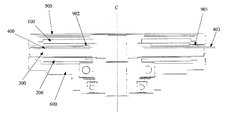
- FIG. 2 is a cross-sectional view of the motor of one embodiment.
- FIG. 3 is a schematic view of a stator and a circuit board of a motor according to an embodiment.
- FIG. 4 is a view showing a state in which the sensor magnetic pole element of the motor of one embodiment is not mounted in the through hole of the circuit board.
- FIG. 5 is a view showing a state in which the sensor magnetic pole element of the motor of one embodiment is mounted in the through hole of the circuit board.
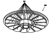
- FIG. 6 is a schematic view of a magnet-equipped rotor.
- FIG. 7 is a view showing the installation position of the coil of the motor of one embodiment.
- FIG. 8 is a view showing an example of the installation position of the sensing element of the motor of one embodiment.
- FIG. 9 is a view showing another example of the installation position of the sensing element of the motor of one embodiment.
- FIG. 10 is a schematic view of a rotor provided with an encoder disk.
- FIG. 11 is another schematic view of a rotor provided with an encoder disk.
- the terms “first”, “second” etc are used to distinguish different elements, but indicate the spatial arrangement, temporal order etc etc of these elements Rather, these elements should not be limited to these terms.
- the term “and / or” includes any one and all combinations of one or more of the associated listed items.
- the terms “include”, “have”, “include” etc mean the presence of the described feature, element, element or assembly, but one or more of the other feature, element, element or It does not exclude the presence or addition of an assembly.
- the radial direction is a direction parallel to the direction extending along the axis
- the radial direction around the axis is radial direction
- the circumferential direction around the axis is circumferential direction.
- the motor is axially disposed at a predetermined distance from a shaft (not shown) rotatably disposed about a central axis C, at least one of which is a magnet
- Two rotors 100, 200 (in this example, it is illustrated that the rotor 100 has a magnet, and for the arrangement of the magnets, the prior art can be referred to) and the two rotors.
- a stator 300 having a plurality of stator cores 301 arranged in the circumferential direction and a plurality of coils 302 wound around the plurality of stator cores 301, and the rotor 300 having a stator 300 and a magnet.
- the circuit board 400 is provided.
- the circuit board 400 faces the rotor 100. That is, the projection of the main body (that is, the disk-like portion) of the circuit board 400 on the plane perpendicular to the axis and the projection on the plane perpendicular to the axis of the rotor 100 overlap.
- FIG. 3 is a schematic view of the stator 300 and the circuit board 400 of the motor according to the present embodiment.
- the circuit board 400 is disposed in the circumferential direction, and has a plurality of slotted holes 401 penetrating the circuit board 400 in the axial direction.
- the plurality of stator cores 301 are fitted.
- one turn on the radially outer side of the slot 401 in the circuit board 400 is referred to as the outer ring of the circuit board 400 and marked 404, and the radial inner side of the slot 401 on the circuit board 400.
- One turn is called the inner ring of the circuit board 400 and is marked 405.
- the stator core can be fitted in the circuit board by providing the slot in the circuit board with an appropriate slot according to the outer shape of the stator core, and the positioning of the stator core can be assisted. Without increasing the axial height of the stator, the axial dimensions of the motor are reduced and the mounting complexity is reduced.
- the motor is an axial flux motor having the structure of both air gaps-outer rotor-inner stator.
- the inner stator is composed of each independent stator core and a coil wound around each stator core.
- each independent stator core of the inner stator needs to be mounted at a predesigned position by an appropriate jig or means at the time of assembly, but according to the configuration of this embodiment, it is suitable for a circuit board By providing such a slot, the stator core can be accommodated and the positioning of the stator core can be assisted.
- the motor further includes the front cover 500 and the rear cover 600, but the structure and function of the front cover 500 and the rear cover 600
- the present invention is not limited to this embodiment.
- each slot 401 is matched with the shape of each stator core 301.
- the slots 401 and the stator core 301 are both provided in a substantially fan shape as shown in FIGS. 1 and 3.
- the number of slots 401 is not limited, and preferably corresponds to the number of stator cores 301.
- the motor performance can be improved by providing 12 slots 401 in the circuit board 400 so as to match the number (12) of the stator cores 301.
- the circuit board 400 and the stator 300 can be fixed by resin potting.
- the coil 302 of the stator core 301 is potted with resin and fixed together with the circuit board 400 to increase rigidity.
- the plane on which the surface on the one side in the axial direction of the circuit board 400 is located may be the same as the plane on which the surface on the one side in the axial direction of the stator 300 is located. It may be on the other side in the axial direction with respect to the surface of. That is, after circuit board 400 is mounted on stator 300, the surface of stator core 301 is flush with the surface of circuit board 400, or the surface of stator core 301 is higher than the surface of circuit board 400. . Therefore, the installation of the circuit board 400 does not occupy an additional axial height of the stator, the gap between the stator and the rotor becomes smaller, and the torque can be increased.
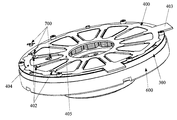
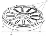
- a plurality of through holes such as the through holes 402 shown in FIG. 4 and FIG. 5 may be provided on the periphery of the circuit board 400, and the sensing magnetic pole element 700 may be mounted on the plurality of through holes 402. Good.
- FIG. 4 shows the sensing magnetic pole element 700 not mounted in the through hole 402 of the circuit board 400
- FIG. 5 shows the sensing magnetic pole element 700 mounted in the through hole 402 of the circuit board 400.
- a through hole is provided in advance in the circuit board so as to accommodate the sensing magnetic pole element, leaving only the fillet of the sensing magnetic pole element on the circuit board, and embedding the sensing magnetic pole element in the through hole during mounting.
- the fillet of the pole sensing element is connected to the pin of the circuit board.
- a circuit board is used to connect coil paths, but when a sensing magnetic pole element such as Hall IC is mounted on the surface of the circuit board facing the rotor magnet, the air gap of the motor is larger than the height of the element. It is not a practical benefit because it needs to be done. Also, mounting the sensing pole element on the surface of the circuit board facing away from the rotor magnet tends to interfere with the coils of the stator core, where special insulation protection is needed, increasing process and assembly complexity.
- a sensing magnetic pole element such as Hall IC
- a through hole is provided in advance at a position on the circuit board where the sensing magnetic pole element is mounted, so that only the fillet of the sensing magnetic pole element is left on the circuit board to sense The height required for mounting the pole element is reduced and the sensing pole element is located at the same layer height as the circuit board, thereby reducing the axial height of the motor.
- the plurality of through holes 402 are located radially outward. Good. That is, the plurality of through holes 402 are positioned between the inner ring 405 and the outer ring 404 of the circuit board 400 and closer to the outer ring 404. According to this configuration, since the position of the slot 401 corresponds to the magnet of the rotor 100, the length on the inner diameter side of the magnet can be increased to compensate for the inaccuracy of the detection accuracy.
- FIG. 4 and FIG. 5 shows an example in which the number of through holes 402 is three, the present embodiment is not limited to this, and in the specific implementation, the through holes 402 A number and location can be provided.
- FIG. 6 is a schematic view of one embodiment of the rotor 100. As shown in FIG. There are magnets 101, each corresponding to the slot 401.
- a wire 800 axially opposed to the above-described coil 302 of the stator 300 may be disposed at the position of the circuit board 400 surrounding at least one slot 401.
- the stator core 301 surrounded by it is detected by an inductance signal obtained during operation to be transmitted to the external controller, and through specific logic operations, the speed, position, and current state of the motor rotor are estimated. Do.
- FIG. 7 shows the case where the wiring 800 is disposed at the position of the circuit board 400 that encloses the three groove holes 401
- the present embodiment is not limited to this, and another number of groove holes 401 may be surrounded.
- the wire 800 may be disposed, or the slot 401 at another position may be surrounded.
- the line 800 may be a spiral circuit coil or may be another type of circuit coil, and the present embodiment is not limited to this.
- a sensing element such as a temperature sensitive IC or a thermistor may be provided at a position on the circuit board 400 corresponding to the radially inner side or the radially outer side of the magnet 101.
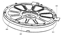
- FIG. 8 shows the case where the sensing element 901 is provided at the position (the outer ring 404 of the circuit board 400) of the circuit board 400 corresponding to the radial outside of the magnet 101.
- FIG. 9 shows the case where the sensing element 902 is provided at the position (inner ring 405 of the circuit board 400) of the circuit board 400 corresponding to the inner side in the radial direction of the magnet 101. The position where the sensing element of FIGS.
- the sensing element 901 is not disposed in the area corresponding to the magnetic pole, and is not disposed in the area susceptible to interference. Therefore, the sensing element 901 detects the temperature inside the stator during motor operation. Can.
- the circuit board 400 has the terminal portion 403 extending radially outward, and the sensing element 901 is provided closer to the terminal portion 403 of the circuit board 400. It is also good. In this case, the above effect can be obtained similarly.
- the sensing element may be a position sensing element such as a position sensing IC having a transmitting end and a receiving end.
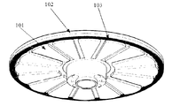
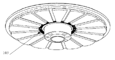
- the rotor 100 may have a plurality of magnets 101 as shown in FIG. 6, and as shown in FIG. 10, a rotor frame 102 supporting the plurality of magnets 101 may be used. Further, an optical encoder disk may be disposed on the rotor frame 102. 10 and 11 show the arrangement position of the optical encoder disk 103, respectively.
- the optical encoder disk 103 is located radially inward of the plurality of magnets 101 (FIG. 11) or radially outward of the plurality of magnets 101 (FIG. 10). It can be located.
- the transmission end (optical transmission head) of the position sensing IC disposed on the circuit board 400 transmits a light source onto the encoder disk 103, and a stripe (notch) on the encoder disk 103 causes a difference between bright and dark A signal is reflected, and the receiving end (optical read head) of this position sensing IC receives this signal to read the angular position, and converts this signal into information on the angle and velocity of the rotor 100.
- the signal may be transmitted to the motor control unit (not shown) on the circuit board 400 or the outside via the terminal portion 403 to perform corresponding processing.
- the axial height of the motor does not increase despite the fact that the encoder disc 103 and the corresponding position sensing element are arranged in the motor's construction space.
- both the encoder disk 103 and the position sensing element can be provided on the outer ring 404 or the inner ring 405 of the circuit board 400, two options of low cost and high accuracy are provided.
- the optical encoder disc 103 may be constructed of a reflective material to reflect the light source transmitted from the optical transmission head of the position sensing IC.
- the optical encoder disk 103 and the rotor frame 102 may be integrally formed or separately formed. In the case of forming separately, the optical encoder disc 103 may be bonded to the rotor frame 102 via an adhesive, but the present embodiment is not limited to this, and a more flexible selection is possible. It is possible.
- the design of the circuit board can aid in the assembly and positioning of the stator core, and can simplify the construction and assembly complexity. Further, by mounting the magnetic pole sensing element in the opposing area of the rotor magnet, the rotor position can be detected reliably, and the space occupied by the circuit board and the element can be minimized. Also, by placing a spiral coil around the slot of the circuit board, the core's inductance can be additionally detected and used for back-end controller analysis and recording for pre-estimated sensing of faults or errors Use for Also, by placing various necessary sensing elements at other locations on the circuit board, the operating state of the motor can be recorded or transmitted, and used for analysis and recording of back-end controllers Used for pre-estimation sensing.
- a smart motor that feeds back a plurality of physical state signals so as to be compatible with future robot, car, home, and commercial application fields while maintaining compact and high-performance features
- a motor having a function can be provided.
- Another exemplary embodiment is to provide an electric device including the motor described in the above embodiment and other conventional parts.
- This embodiment does not limit the configuration, installation method and function of the conventional parts, and can refer to the prior art.
- a circuit board is built in an inner stator of a motor (for example, a thin axial magnetic flux motor) to connect motor coil wires and arrange various necessary sensing elements.
- a motor for example, a thin axial magnetic flux motor
- the height space occupied by the stator can be reduced without increasing the air gap or the axial height of the motor, and the axial dimension of the motor can be reduced.
Landscapes
- Engineering & Computer Science (AREA)
- Power Engineering (AREA)
- Microelectronics & Electronic Packaging (AREA)
Abstract
モータであって、中心軸線を中心として転可能に配置されたシャフトと、所定の間隔を空けて軸方向に配置され、少なくとも一方が磁石を有する2つのロータと、前記2つのロータの間に配置され、周方向に配置された複数のステータコアと、前記複数のステータコアに巻されたコイルとを有するステータと、前記ステータと磁石を有する前記ロータとの間に設けられた回路基板と、を備える。前記回路基板は、前記回路基板を軸方向に貫通する周方向に配置された複数の溝穴を有する。前記複数のステータコアは、前記複数の溝穴に嵌め込まれている。
Description
本出願は、2017年11月30日に出願された中国出願第201711239740.0号に基づく優先権を主張し、当該中国出願に記載された全ての記載内容を援用するものである。
本発明は、モータの分野に関し、特に、モータ及び該モータを含む電気機器に関する。
従来のモータの一例として、日本国特開2007-274850号公報に開示されるモータが挙げられる。従来のモータでは、モータのステータアセンブリのコイルは、まずロータの外部に引き出される必要があり、それから回路基板に接続され、且つ、この回路基板に感知素子が取り付けられてロータの他の側の付加的な取り付け磁極に誘導される。このようにして、モータの軸方向のスペースが増加し、組み立てが困難になる。
上記の問題を解決するために、1つの対策は、回路基板をステータアセンブリの内部に配置し、検出素子を回路基板上に配置することである。しかし、このようにすると、感知素子に必要なスペースを考慮する必要があり、エアギャップが長くなり、モータ特性が低下したり、モータの軸方向長さが増大したり、ステータ組立体のコイルの利用可能なスペースが消費されたりする。
上記課題を解決するために、他の対策は、ロータ磁極の転範囲内ではなく、ステータに、回路基板を配置し、回路基板における、磁極に近い箇所に磁極検出素子を配置することである。しかしながら、このようにすると、磁石の感知の精度が高くない、回路の利用可能な空間が少なく、感知作用の他の素子を配置することができないという問題に直面する。
上記課題を解決するために、他の対策は、ロータ磁極の転範囲内ではなく、ステータに、回路基板を配置し、回路基板における、磁極に近い箇所に磁極検出素子を配置することである。しかしながら、このようにすると、磁石の感知の精度が高くない、回路の利用可能な空間が少なく、感知作用の他の素子を配置することができないという問題に直面する。
なお、上述した技術的背景の説明は、本発明の技術案を明確かつ完全に説明するためのものであり、当業者の理解を容易にするためになされたものである。これらの構成が本発明の背景技術の項で説明されているだけでは、上記の構成は当業者には周知であるとは考えられない。
上記課題のうちの少なくとも1つを解決するために、本発明の例示的な実施形態は、モータの軸方向の小型化を図ることができるモータ及びこれを備えた電気機器を提供することを目的とする。
本発明の例示的な実施形態は、モータであって、中心軸線を中心として回転可能に配置されたシャフトと、所定の間隔を空けて軸方向に配置され、少なくとも一方が磁石を有する2つのロータと、前記2つのロータの間に配置され、周方向に配置された複数のステータコアと、前記複数のステータコアに巻されたコイルとを有するステータと、前記ステータと磁石を有する前記ロータとの間に設けられた回路基板と、を備える。前記回路基板は、前記回路基板を軸方向に貫通する周方向に配置された複数の溝穴を有する。前記複数のステータコアは、前記複数の溝穴に嵌め込まれている
また、本発明の例示的な実施形態は、電気機器であって、上述のモータを備える。
本発明の例示的な実施形態のモータによれば、エアギャップやモータの軸方向高さを増加させず、ステータの占有する高さスペースを低減でき、さらに、モータ軸方向寸法を減少させ、モータの薄型化ができる。
以下の説明および添付の図面を参照して、本発明の例示的な実施形態を詳細に開示し、本発明の原理が適用され得る方法を示す。本発明の例示的な実施形態は、その範囲を制限するものではない。本発明の例示的な実施形態は、添付の特許請求の範囲の精神および範囲内で、多くの変更、修正、および等価物を含む。
1つの例示的な実施形態について説明及び/又は図示された特徴は、1つ以上の他の実施形態において同一又は類似の方法で使用され、他の実施形態の特徴と組み合わせ、又は代替され得る。
用語「含む」は、本明細書で使用される場合、特徴、構成要素、ステップ、またはアセンブリの存在を意味するが、1つ以上の他の特徴、構成要素、ステップ、またはアセンブリの存在または追加を排除するものではない。
本発明の例示的な実施形態の1つの図又は1つの実施形態に記載された要素及び特徴は、1つ以上の他の図又は実施形態に示された要素及び特徴と組み合わせることができる。さらに、図面において、同様の参照番号は、いくつかの図面中の対応する構成要素を示し、1つ以上の実施形態で使用される対応する構成要素を示すために使用され得る。
本発明の例示的な実施形態において、用語「第1」、「第2」などは、異なる要素を区別するために使用されるが、これらの要素の空間的配列や時間的順序などを示すものではなく、これらの要素はこれらの用語に限定されるべきではない。用語「および/または」は、関連して列挙された用語の1つまたは複数のうちのいずれか1つおよび全ての組み合わせを含む。用語「含む」、「有する」、「備える」などは、記載されている構成要件、要素、素子、またはアセンブリの存在を意味しますが、1つ以上の他の構成要件、要素、素子、またはアセンブリの存在または追加を除外しません。
本発明の例示的な実施形態において、単数形の「1つ」、「該」などは複数形を含み、広義に「1種」又は「1種類」に解釈されるべきものであり、「1個」との意味に限定されるものではない。さらに、特に明確に示していない限り、用語「前記」は、単数形および複数形の両方を含むものと解釈すべきである。さらに、特に明確に示していない限り、用語「基づく」は、「少なくとも部分的に基づく」との意味に理解すべきである。
本発明の例示的な実施形態では、説明の便宜上、軸に沿って延びる方向と平行な方向をラジアル方向、軸を中心とする半径方向をラジアル方向、軸を中心とする円周方向を周方向と呼ぶが、これは説明の便宜上のものであり、モータの使用及び製造の時の向きを限定しない。
以下、本発明の例示的な実施形態について図面を参照して説明する。これらの実施形態は例示に過ぎず、本発明を限定するものではない。
図1及び図2に示すように、このモータは、中心軸線Cを中心として回転可能に配置されたシャフト(図示せず)と、所定の間隔を空けて軸方向に配置され、少なくとも一方が磁石(図示せず)を有する2つのロータ100、200(本実施例では、ロータ100が磁石を有することを例示し、該磁石の配置方式について、従来の技術を参照できる)と、前記2つのロータ100,200の間に配置され、周方向に配置された複数のステータコア301と、該複数のステータコア301に巻されたコイル302とを有するステータ300と、ステータ300と磁石を有するロータ100との間に設けられている回路基板400を備える。
本実施形態では、この回路基板400がロータ100に対向する。すなわち、回路基板400の本体(すなわち円盤状の部分)の、軸に垂直な面への投影と、ロータ100の軸に垂直な面への投影とが重なる。
本実施形態では、この回路基板400がロータ100に対向する。すなわち、回路基板400の本体(すなわち円盤状の部分)の、軸に垂直な面への投影と、ロータ100の軸に垂直な面への投影とが重なる。
図3は、本実施形態のモータのステータ300と回路基板400の模式図である。図3に示すように、本実施形態において、回路基板400は、周方向に配置され、回路基板400を軸方向に貫通する複数の溝穴401を有し、この複数の溝穴401内には、上記複数のステータコア301が嵌め込まれている。本実施形態では、説明の便宜上、回路基板400における溝穴401の径方向外側の1ターンを回路基板400の外輪と呼び、且つ404と標記し、回路基板400における溝穴401の径方向内側の1ターンを回路基板400の内輪と呼び、且つ405と標記する。
この構成により、回路基板に、ステータコアの外形に合わせて適当な溝穴を設けてステータコアを収容することで、ステータコアを回路基板内に嵌合させ、ステータコアの位置決めを補助することができ、且つ、ステータの軸方向高さを増加せず、モータの軸方向寸法を低減し、実装の複雑度を低減することになる。
この構成により、回路基板に、ステータコアの外形に合わせて適当な溝穴を設けてステータコアを収容することで、ステータコアを回路基板内に嵌合させ、ステータコアの位置決めを補助することができ、且つ、ステータの軸方向高さを増加せず、モータの軸方向寸法を低減し、実装の複雑度を低減することになる。
本実施形態では、そのモータが、両エアギャップ‐アウターロータ‐インナステータの構造を有する軸方向磁束モータである。ただし、前記インナステータが、各独立したステータコアと、各ステータコアに巻装されたコイルとで構成される。一般に、該インナステータの各独立したステータコアは、組立時に、適当的な治具や手段で、予め設計された位置に取り付けられる必要があるが、本実施形態の構成によれば、回路基板に適切な溝穴を設けることで、該ステータコアを収納し、該ステータコアの位置決めを補助することができる。
また、本実施形態では、図1及び図2に示すように、そのモータが前カバー500及び後カバー600をさらに備えているが、前カバー500及び後カバー600の構造及び機能について、従来の技術を参照でき、本実施形態に限定されるものではない。
また、本実施形態では、図1及び図2に示すように、そのモータが前カバー500及び後カバー600をさらに備えているが、前カバー500及び後カバー600の構造及び機能について、従来の技術を参照でき、本実施形態に限定されるものではない。
本実施形態では、図1及び図3に示すように、各溝穴401の形状は、各ステータコア301の形状と合わせる。例えば、溝穴401及びステータコア301は、いずれも図1及び図3に示すように略扇形状に設けられている。これにより、両者を組み立てた際に両者を互いに嵌め合うことができ、溝穴401内へのステータコア301の埋め込みを容易にしている。
本実施形態では、溝穴401の個数に制限はなく、ステータコア301の個数に相当することが好ましい。例えば、回路基板400に、ステータコア301の個数(12個)に合わせるように、溝穴401を12個設け、モータ性能を向上させることができる。
本実施形態では、溝穴401の個数に制限はなく、ステータコア301の個数に相当することが好ましい。例えば、回路基板400に、ステータコア301の個数(12個)に合わせるように、溝穴401を12個設け、モータ性能を向上させることができる。
本実施形態において、回路基板400及びステータ300は、樹脂ポッティングによって固定させることができる。例えば、ステータコア301のコイル302を回路基板400とともに樹脂でポッティングして固定させ、剛性を高める。
本実施形態において、回路基板400の軸方向一方側の面が位置する平面は、ステータ300の軸方向一方側の面が位置する平面と同一であってもよいし、ステータ300の軸方向一方側の面よりも軸方向他方側であってもよい。すなわち、回路基板400をステータ300に載置した後、ステータコア301の表面が回路基板400の表面と同一平面上にあるか、または、ステータコア301の表面が回路基板400の表面よりも高くなっている。したがって、回路基板400の設置がステータの軸方向高さを余分に占有せず、ステータとロータとの間の隙間が小さくなり、トルクを高めることができる。
本実施形態において、回路基板400の周縁に、図4及び図5に示す貫通孔402のような貫通孔を複数設けてもよい、その複数の貫通孔402に感知磁極素子700を実装してもよい。図4は、感知磁極素子700が回路基板400の貫通孔402に実装されていない状態を示す図であり、図5は、感知磁極素子700が回路基板400の貫通孔402に実装されている状態を示す図である。この構成により、感知磁極素子を収容するように、予め回路基板に貫通孔を設けておくことで、感知磁極素子のフィレットのみを回路基板に残し、実装時に該感知磁極素子をこの貫通孔に埋め込んで、磁極感知素子のフィレットが回路基板のピンに接続される。
一般に、回路基板はコイル路を接続するために使用されるが、感知磁極素子、例えばHall ICなどを回路基板のロータマグネットに対向する表面に搭載すると、モータのエアギャップを素子の高さよりも大きくする必要があるため、実用上のメリットではありません。また、感知磁極素子を回路基板のロータマグネットに背向する表面に搭載すると、ステータコアのコイルと干渉しやすくなり、そこで、特別な絶縁保護が必要となり、工程と組み立ての複雑さが増加する。
本実施形態の構成により、回路基板の感知磁極素子が搭載される位置に、当該感知磁極素子を収容するように予め貫通孔を設けて、感知磁極素子のフィレットのみを回路基板上に残し、感知磁極素子の実装に必要な高さを低減し、かつ感知磁極要素を回路基板と同じ層の高さ位置に位置させ、これによりモータの軸方向高さを減少させる。
本実施形態において、前記複数の貫通孔402は、図4及び図5に示すように、回路基板400の隣接する2つの溝穴401の間であって、径方向外側寄りに位置していてもよい。すなわち、上記複数の貫通孔402は、回路基板400の内輪405と外輪404との間であって、外輪404寄りに位置している。この構成によれば、溝穴401の位置がロータ100の磁石に対応しているので、磁石内径側の長さを長くして検知精度の不正確さを補うことができ、磁石外径側の長さの増加の場合に、磁石使用量の過度な増加やモータ外径の増加といった欠点があることに対し、モータの小型化に有利である。図4及び図5の例では、貫通孔402が3つである例を示したが、本実施形態はこれに限定されるものではなく、具体的な実施において、必要に応じて貫通孔402の数及び位置を設けることができる。なお、本実施形態では、ロータ100が複数の磁石を有する例を示しているが、図6はこのロータ100の一実施形態の模式図であり、図6に示すように、ロータ100は複数の磁石101があり、それぞれ前記溝穴401に対応している。
本実施形態では、図7に示すように、少なくとも1つの溝穴401を取り囲む回路基板400の位置に、ステータ300の前述のコイル302と軸方向に対向する配線800を配置してもよい。これにより、それに囲まれたステータコア301が運転時に誘導され得られるインダクタンス信号を検出することにより、外部コントローラに伝達され、特定の論理演算を経てモータのロータの速度、位置、さらには電流状態を推定する。
図7では、3つの溝穴401を囲う回路基板400の位置に配線800を配置した場合を示しているが、本実施形態はこれに限定されず、他の数の溝穴401を囲うように配線800を配置してもよいし、他の位置の溝穴401を囲ってもよい。本実施形態では、図7に示すように、線路800は螺旋状の回路コイルであってもよく、他のタイプの回路コイルであってもよく、本実施形態ではこれに限定されない。
本実施形態において、磁石101の径方向内側又は径方向外側に対応する回路基板400上の位置に、感温IC、サーミスタ等の感知素子を設けてもよい。図8は、磁石101の径方向外側に対応する回路基板400の位置(回路基板400の外輪404)に感知素子901を設けた場合を示している。図9は、磁石101の径方向内側に対応する回路基板400の位置(回路基板400の内輪405)に感知素子902を設けた場合を示している。図8及び図9の感知素子が配置される位置は一例であり、具体的な実施過程では、感知素子は回路基板400の内側リング405又は外側リング404以外の他の位置に配置されてもよい。これにより、感知素子901が磁極に対応する領域に配置されることがなく、干渉しやすい領域に配置されることもないので、この感知素子901によってモータ運転時のステータ内部の温度を検知することができる。
本実施形態において、回路基板400は、図8及び図9に示すように、径方向外側に延びる端子部403を有し、感知素子901は、回路基板400の端子部403寄りに設けられていてもよい。これでは、同様に上記効果を得ることができる。
本実施形態では、該感知素子は、送信端および受信端を有する位置感知ICなどの位置感知素子であってもよい。
本実施形態において、前記ロータ100は、図6に示すように、複数の磁石101を有していてもよく、また、図10に示すように、当該複数の磁石101を支持するロータフレーム102をさらに有し、当該ロータフレーム102上に光学エンコーダディスクが配置されていてもよい。図10および図11は、それぞれ、光学エンコーダディスク103の配置位置を示す。
本実施形態では、図10及び図11に示すように、この光学エンコーダディスク103は、前記複数の磁石101の径方向内側(図11)又は前記複数の磁石101の径方向外側(図10)に位置することができる。これにより、回路基板400に配置された位置感知ICの送信端(光学送信ヘッド)は、このエンコーダディスク103上に光源を送信し、このエンコーダディスク103上のストライブ(刻み目)で明暗間差の信号を反射し、この位置感知ICの受信端(光学読取ヘッド)がこの信号を受けて、角度位置の判読を行い、この信号をロータ100の角度と速度の情報に換算する。本実施形態において、前記信号は、前記端子部403を介して外部又は回路基板400上のモータ制御ユニット(図示せず)に伝達されて対応する処理が行われてもよい。この構成では、モータの構成空間内にはエンコーダディスク103及び対応の位置感知素子が配置されているにもかかわらず、モータの軸方向高さが増加することはない。また、エンコーダディスク103と位置感知素子とをいずれも回路基板400の外輪404または内輪405に設けることができるので、低コストと高精度との2つのオプションが提供される。
この実施形態では、その光学エンコーダディスク103は、位置感知ICの光学送信ヘッドから送信された光源を反射するように反射性材料で構成されてもよい。
本実施形態において、光学エンコーダディスク103とロータフレーム102とは、一体的に形成されていてもよいし、別体に形成されていてもよい。また、別体に形成した場合には、光学エンコーダディスク103が接着剤を介してロータフレーム102に接着されてもよいが、本実施形態はこれに限定されるものではなく、より柔軟な選択が可能である。
本実施形態において、光学エンコーダディスク103とロータフレーム102とは、一体的に形成されていてもよいし、別体に形成されていてもよい。また、別体に形成した場合には、光学エンコーダディスク103が接着剤を介してロータフレーム102に接着されてもよいが、本実施形態はこれに限定されるものではなく、より柔軟な選択が可能である。
上記の実施形態では、回路基板の設計は、ステータコアの組み立て及び位置決めを補助でき、構造および組み立ての複雑さを単純化することができる。また、ロータ磁石の対向する範囲に磁極感知素子を取り付けることにより、ロータ位置を確実に検出することができ、且つ回路基板と素子が占拠する空間を最小化することができる。また、回路基板の溝穴の周囲に螺旋コイルを配置することにより、コアのインダクタンスを追加的に検出することができ、バックエンド制御器の解析と記録に用いて、故障又はエラーの事前推定感知に用いる。また、回路基板の他の位置に各種の必要な検知素子を配置することにより、モータの動作状態を記録又は伝送することができ、バックエンド制御器の分析及び記録に用いて、故障又はエラーの事前推定感知に用いる。
本実施形態のモータの構成により、コンパクトで高性能な特徴を維持しつつ、将来のロボット、車載、家庭、商用の応用分野製品に適合するように複数の物理的状態信号をフィードバックするスマートモータの機能を備えたモータを提供することができる。
その他の例示的な実施形態としては、上述の実施形態で説明したモータと、その他の従来部品とを備えた電気機器を提供するものである。本実施形態は、前記従来部品の構成、設置方式及び機能を制限するものではなく、従来技術を参照することができる。
本実施形態では、上述の実施形態のモータの構造に基づき、モータ(例えば薄型軸方向磁束モータ)のインナステータに回路基板を内蔵させてモータコイル線を接続し、必要な各種感知素子を配置することにより、エアギャップやモータ軸方向高さを増加させることなく、ステータの占有する高さスペースを低減でき、さらに、モータの軸方向寸法が小さくなる。
本実施形態では、上述の実施形態のモータの構造に基づき、モータ(例えば薄型軸方向磁束モータ)のインナステータに回路基板を内蔵させてモータコイル線を接続し、必要な各種感知素子を配置することにより、エアギャップやモータ軸方向高さを増加させることなく、ステータの占有する高さスペースを低減でき、さらに、モータの軸方向寸法が小さくなる。
以上、本発明を特定の実施形態に関連して説明したが、これらの説明は例示的なものであり、本発明の範囲を限定するものではないことは当業者には明らかであろう。当業者は、本発明の精神および原理に基づいて、本発明の範囲内にある様な変更および修正を行うことができる。
100,200…ロータ、102…ロータフレーム、103…光学エンコーダディスク、300…ステータ、301…ステータコア、400…回路基板、401…溝穴、402…貫通孔、403…端子部、700…感知磁極素子、800…配線、901…感知素子
Claims (18)
- 中心軸線を中心として転可能に配置されたシャフトと、
所定の間隔を空けて軸方向に配置され、少なくとも一方が磁石を有する2つのロータと、
前記2つのロータの間に配置され、周方向に配置された複数のステータコアと、前記複数のステータコアに巻されたコイルとを有するステータと、
前記ステータと磁石を有する前記ロータとの間に設けられた回路基板と、
を備えるモータにおいて、
前記回路基板は、前記回路基板を軸方向に貫通する周方向に配置された複数の溝穴を有し、前記複数のステータコアは、前記複数の溝穴に嵌め込まれていることを特徴とするモータ。 - 前記回路基板の軸方向一方側の面が位置する平面は、前記ステータの軸方向一方側の面が位置する平面と同一又は前記ステータの軸方向一方側の面よりも軸方向他方側に位置することを特徴とする請求項1に記載のモータ。
- 前記回路基板の周縁には、さらに、複数の貫通孔が設けられ、前記複数の貫通孔内に、感知磁極素子が実装されていることを特徴とする請求項1又は2に記載のモータ。
- 前記複数の貫通孔は、前記回路基板の隣り合う2つの溝穴の間の径方向外側寄りに位置していることを特徴とする請求項3に記載のモータ。
- 少なくとも1つの前記溝穴を囲う前記回路基板の位置には、前記ステータの前記コイルと軸方向に対向する配線が配置されていることを特徴とする請求項1から4のいずれか1項に記載のモータ。
- 前記配線は螺旋状であることを特徴とする請求項5に記載のモータ。
- 前記回路基板の、前記磁石の半径方向内側または半径方向外側に対応する位置に、感知素子がさらに設けられていることを特徴とする請求項1から6のいずれか1項に記載のモータ。
- 前記回路基板は、径方向外側に延びる端子部をさらに有し、前記感知素子は、前記端子部に近接した位置に設けられていることを特徴とする請求項7に記載のモータ。
- 前記感知素子は、送信端と受信端とを有する位置感知素子であることを特徴とする請求項7又は8に記載のモータ。
- 前記磁石は複数であり、前記ロータは、複数の前記磁石を支持するロータフレームをさらに有し、前記ロータフレームには、光学エンコーダディスクが配置されていることを特徴とする請求項1から9のいずれか1項に記載のモータ。
- 前記光学エンコーダディスクは、複数の前記磁石の半径方向内側または半径方向外側に配置されることを特徴とする請求項10に記載のモータ。
- 前記光学エンコーダディスクは、反射性材料からなることを特徴とする請求項10又は11に記載のモータ。
- 前記光学エンコーダディスクは、前記ロータフレームと一体に形成されているか、又は別体に形成されていることを特徴とする請求項10から12のいずれか1項に記載のモータ。
- 前記光学エンコーダディスクが前記ロータフレームと別体に形成されている場合、前記光学エンコーダディスクは、接着剤により前記ロータフレームに接着されていることを特徴とする請求項13に記載のモータ。
- 各前記溝穴の形状は、各前記ステータコアの形状に合わせることを特徴とする請求項1から14のいずれか1項に記載のモータ。
- 前記溝穴の数は12個であることを特徴とする請求項1から15のいずれか1項に記載のモータ。
- 前記回路基板および前記ステータは、樹脂ポッティングによって固定されていることを特徴とする請求項1から6のいずれか1項に記載のモータ。
- 請求項1から17のいずれか1項に記載のモータを含むことを特徴とする電気機器。
Priority Applications (3)
| Application Number | Priority Date | Filing Date | Title |
|---|---|---|---|
| JP2019557094A JP7205488B2 (ja) | 2017-11-30 | 2018-11-02 | モータおよび該モータを含む電気機器 |
| US16/767,118 US20200373817A1 (en) | 2017-11-30 | 2018-11-02 | Motor and electric device including the motor |
| EP18883711.6A EP3719977A4 (en) | 2017-11-30 | 2018-11-02 | MOTOR AND ELECTRICAL DEVICE INCLUDING THIS MOTOR |
Applications Claiming Priority (2)
| Application Number | Priority Date | Filing Date | Title |
|---|---|---|---|
| CN201711239740.0 | 2017-11-30 | ||
| CN201711239740.0A CN109861461A (zh) | 2017-11-30 | 2017-11-30 | 马达以及包含该马达的电气设备 |
Publications (1)
| Publication Number | Publication Date |
|---|---|
| WO2019107074A1 true WO2019107074A1 (ja) | 2019-06-06 |
Family
ID=66665662
Family Applications (1)
| Application Number | Title | Priority Date | Filing Date |
|---|---|---|---|
| PCT/JP2018/040870 Ceased WO2019107074A1 (ja) | 2017-11-30 | 2018-11-02 | モータおよび該モータを含む電気機器 |
Country Status (5)
| Country | Link |
|---|---|
| US (1) | US20200373817A1 (ja) |
| EP (1) | EP3719977A4 (ja) |
| JP (1) | JP7205488B2 (ja) |
| CN (1) | CN109861461A (ja) |
| WO (1) | WO2019107074A1 (ja) |
Cited By (2)
| Publication number | Priority date | Publication date | Assignee | Title |
|---|---|---|---|---|
| JP2022182193A (ja) * | 2021-05-27 | 2022-12-08 | 日本電産株式会社 | ステータの製造方法 |
| DE102023123071A1 (de) | 2022-09-20 | 2024-03-21 | Nidec Corporation | Axialflussmotor |
Families Citing this family (3)
| Publication number | Priority date | Publication date | Assignee | Title |
|---|---|---|---|---|
| CN118056344A (zh) * | 2021-10-07 | 2024-05-17 | 米巴电动汽车有限公司 | 轴流机 |
| CN114665634A (zh) * | 2022-04-09 | 2022-06-24 | 宋子军 | 一种轴向磁通外转子轮毂电机 |
| DE102023002860A1 (de) * | 2023-07-14 | 2025-01-16 | Mercedes-Benz Group AG | Elektrische Maschine, insbesondere für ein Kraftfahrzeug sowie Verfahren zum Herstellen einer solchen elektrischen Maschine |
Citations (6)
| Publication number | Priority date | Publication date | Assignee | Title |
|---|---|---|---|---|
| JPS589563A (ja) * | 1981-07-07 | 1983-01-19 | Mitsubishi Electric Corp | トランジスタモ−タ |
| JPH11146588A (ja) * | 1997-11-10 | 1999-05-28 | Asahi Chem Ind Co Ltd | 検出コイル付モータコイルユニット |
| JP2006087205A (ja) * | 2004-09-15 | 2006-03-30 | Aisan Ind Co Ltd | 電子制御装置及び電動ポンプ |
| JP2007274850A (ja) | 2006-03-31 | 2007-10-18 | Fujitsu General Ltd | アキシャルエアギャップ型電動機 |
| JP2010093872A (ja) * | 2008-10-03 | 2010-04-22 | Nidec Servo Corp | ブラシレスdcモータ |
| JP2016208817A (ja) * | 2015-04-17 | 2016-12-08 | 信越化学工業株式会社 | アキシャルギャップ型回転機 |
Family Cites Families (16)
| Publication number | Priority date | Publication date | Assignee | Title |
|---|---|---|---|---|
| JP2742183B2 (ja) * | 1992-09-10 | 1998-04-22 | 株式会社リコー | ブラシレスモータ |
| JPH07245917A (ja) * | 1993-09-30 | 1995-09-19 | Fuji Electric Co Ltd | 回転位置検出器を備えるサーボモータ |
| JPH08289518A (ja) * | 1995-04-17 | 1996-11-01 | Sankyo Seiki Mfg Co Ltd | 小型モータのfg構造 |
| JPH10127029A (ja) * | 1996-10-21 | 1998-05-15 | Sony Corp | 平面対向型モータとディスク装置 |
| JPH10174276A (ja) * | 1996-12-06 | 1998-06-26 | Matsushita Electric Ind Co Ltd | モータの保護装置 |
| US20020145351A1 (en) * | 2001-04-04 | 2002-10-10 | Sunonwealth Electric Machine Industry Co., Ltd | Double sensing face motor structure |
| JP4696642B2 (ja) | 2004-03-31 | 2011-06-08 | ダイキン工業株式会社 | モータ、送風機、圧縮機及び空気調和機 |
| US7166948B2 (en) * | 2004-09-15 | 2007-01-23 | Petersen Technology Corporation | Apparatus and method for dissipating a portion of the commutation derived collapsing field energy in a multi-phase unipolar electric motor |
| EP1670125A1 (en) * | 2004-12-10 | 2006-06-14 | Deutsche Thomson-Brandt Gmbh | Electric motor |
| JP3799362B1 (ja) * | 2005-08-25 | 2006-07-19 | 山洋電気株式会社 | 磁気センサ付き回転電機 |
| JP4921092B2 (ja) * | 2006-09-26 | 2012-04-18 | 東京パーツ工業株式会社 | 軸方向空隙型ロータと該ロータを備えた軸方向空隙型コアレスモータ。 |
| JP2009261062A (ja) * | 2008-04-14 | 2009-11-05 | Sanyo Electric Co Ltd | ブラシレスモータ |
| JP5629875B2 (ja) * | 2010-08-17 | 2014-11-26 | 日本電産株式会社 | モータ |
| CN102355102A (zh) * | 2011-09-30 | 2012-02-15 | 山东理工大学 | 电动汽车增程器用盘式双转子发电机 |
| CN206041762U (zh) * | 2016-08-29 | 2017-03-22 | 眭华兴 | 一种盘式双动力无铁芯直流电机 |
| KR102622474B1 (ko) * | 2016-12-22 | 2024-01-05 | 주식회사 아모텍 | 다층 기판을 이용한 적층형 스테이터, 이를 이용한 공기 정화 시스템용 모터와 블로워 |
-
2017
- 2017-11-30 CN CN201711239740.0A patent/CN109861461A/zh active Pending
-
2018
- 2018-11-02 JP JP2019557094A patent/JP7205488B2/ja active Active
- 2018-11-02 US US16/767,118 patent/US20200373817A1/en not_active Abandoned
- 2018-11-02 WO PCT/JP2018/040870 patent/WO2019107074A1/ja not_active Ceased
- 2018-11-02 EP EP18883711.6A patent/EP3719977A4/en not_active Withdrawn
Patent Citations (6)
| Publication number | Priority date | Publication date | Assignee | Title |
|---|---|---|---|---|
| JPS589563A (ja) * | 1981-07-07 | 1983-01-19 | Mitsubishi Electric Corp | トランジスタモ−タ |
| JPH11146588A (ja) * | 1997-11-10 | 1999-05-28 | Asahi Chem Ind Co Ltd | 検出コイル付モータコイルユニット |
| JP2006087205A (ja) * | 2004-09-15 | 2006-03-30 | Aisan Ind Co Ltd | 電子制御装置及び電動ポンプ |
| JP2007274850A (ja) | 2006-03-31 | 2007-10-18 | Fujitsu General Ltd | アキシャルエアギャップ型電動機 |
| JP2010093872A (ja) * | 2008-10-03 | 2010-04-22 | Nidec Servo Corp | ブラシレスdcモータ |
| JP2016208817A (ja) * | 2015-04-17 | 2016-12-08 | 信越化学工業株式会社 | アキシャルギャップ型回転機 |
Non-Patent Citations (1)
| Title |
|---|
| See also references of EP3719977A4 |
Cited By (3)
| Publication number | Priority date | Publication date | Assignee | Title |
|---|---|---|---|---|
| JP2022182193A (ja) * | 2021-05-27 | 2022-12-08 | 日本電産株式会社 | ステータの製造方法 |
| JP7714380B2 (ja) | 2021-05-27 | 2025-07-29 | ニデック株式会社 | ステータの製造方法 |
| DE102023123071A1 (de) | 2022-09-20 | 2024-03-21 | Nidec Corporation | Axialflussmotor |
Also Published As
| Publication number | Publication date |
|---|---|
| JPWO2019107074A1 (ja) | 2020-12-03 |
| EP3719977A4 (en) | 2021-09-01 |
| JP7205488B2 (ja) | 2023-01-17 |
| US20200373817A1 (en) | 2020-11-26 |
| EP3719977A1 (en) | 2020-10-07 |
| CN109861461A (zh) | 2019-06-07 |
Similar Documents
| Publication | Publication Date | Title |
|---|---|---|
| JP7205488B2 (ja) | モータおよび該モータを含む電気機器 | |
| US7705505B2 (en) | Brushless Motor | |
| CN108155762B (zh) | 分解器及电机 | |
| KR101555804B1 (ko) | 회전 전기 | |
| JP5709481B2 (ja) | モータ | |
| EP3706293B1 (en) | Motor | |
| KR102128452B1 (ko) | 모터 | |
| JP2007060844A (ja) | 磁気センサ付き回転電機 | |
| JP2010158094A (ja) | ブラシレスモータ | |
| JP2007221976A (ja) | ブラシレスモータ | |
| JP2007151314A (ja) | モータ | |
| JP2013090501A (ja) | モータ | |
| CN109923769B (zh) | 旋转位置检测装置 | |
| CN112136266B (zh) | 编码器及伺服电动机 | |
| US12445018B2 (en) | Rotor for electric motor equipped with an electronic circuit | |
| JP5368524B2 (ja) | レゾルバステータ構造 | |
| JP2005229698A (ja) | ブラシレスモータ | |
| JP5729439B2 (ja) | ブラシレスモータ | |
| JP2009273292A (ja) | ブラシレスモータ | |
| JP4875857B2 (ja) | 回転電機 | |
| JP2014180107A (ja) | 回転電機 | |
| KR20180085494A (ko) | 로터 위치 감지장치 및 이를 포함하는 모터 | |
| CN223885079U (zh) | 电机 | |
| KR102897210B1 (ko) | 모터 | |
| JP2006352979A (ja) | 回転電機 |
Legal Events
| Date | Code | Title | Description |
|---|---|---|---|
| 121 | Ep: the epo has been informed by wipo that ep was designated in this application |
Ref document number: 18883711 Country of ref document: EP Kind code of ref document: A1 |
|
| ENP | Entry into the national phase |
Ref document number: 2019557094 Country of ref document: JP Kind code of ref document: A |
|
| NENP | Non-entry into the national phase |
Ref country code: DE |
|
| ENP | Entry into the national phase |
Ref document number: 2018883711 Country of ref document: EP Effective date: 20200630 |