WO2019107175A1 - 送信装置、送信方法、受信装置および受信方法 - Google Patents
送信装置、送信方法、受信装置および受信方法 Download PDFInfo
- Publication number
- WO2019107175A1 WO2019107175A1 PCT/JP2018/042386 JP2018042386W WO2019107175A1 WO 2019107175 A1 WO2019107175 A1 WO 2019107175A1 JP 2018042386 W JP2018042386 W JP 2018042386W WO 2019107175 A1 WO2019107175 A1 WO 2019107175A1
- Authority
- WO
- WIPO (PCT)
- Prior art keywords
- stream
- decoding
- display area
- partition
- wide
- Prior art date
- Legal status (The legal status is an assumption and is not a legal conclusion. Google has not performed a legal analysis and makes no representation as to the accuracy of the status listed.)
- Ceased
Links
Images











Classifications
-
- H—ELECTRICITY
- H04—ELECTRIC COMMUNICATION TECHNIQUE
- H04N—PICTORIAL COMMUNICATION, e.g. TELEVISION
- H04N21/00—Selective content distribution, e.g. interactive television or video on demand [VOD]
- H04N21/80—Generation or processing of content or additional data by content creator independently of the distribution process; Content per se
- H04N21/81—Monomedia components thereof
- H04N21/816—Monomedia components thereof involving special video data, e.g 3D video
-
- G—PHYSICS
- G06—COMPUTING OR CALCULATING; COUNTING
- G06T—IMAGE DATA PROCESSING OR GENERATION, IN GENERAL
- G06T3/00—Geometric image transformations in the plane of the image
- G06T3/16—Spatio-temporal transformations, e.g. video cubism
-
- H—ELECTRICITY
- H04—ELECTRIC COMMUNICATION TECHNIQUE
- H04N—PICTORIAL COMMUNICATION, e.g. TELEVISION
- H04N19/00—Methods or arrangements for coding, decoding, compressing or decompressing digital video signals
- H04N19/30—Methods or arrangements for coding, decoding, compressing or decompressing digital video signals using hierarchical techniques, e.g. scalability
-
- H—ELECTRICITY
- H04—ELECTRIC COMMUNICATION TECHNIQUE
- H04N—PICTORIAL COMMUNICATION, e.g. TELEVISION
- H04N19/00—Methods or arrangements for coding, decoding, compressing or decompressing digital video signals
- H04N19/50—Methods or arrangements for coding, decoding, compressing or decompressing digital video signals using predictive coding
-
- H—ELECTRICITY
- H04—ELECTRIC COMMUNICATION TECHNIQUE
- H04N—PICTORIAL COMMUNICATION, e.g. TELEVISION
- H04N21/00—Selective content distribution, e.g. interactive television or video on demand [VOD]
- H04N21/20—Servers specifically adapted for the distribution of content, e.g. VOD servers; Operations thereof
- H04N21/21—Server components or server architectures
- H04N21/218—Source of audio or video content, e.g. local disk arrays
- H04N21/21805—Source of audio or video content, e.g. local disk arrays enabling multiple viewpoints, e.g. using a plurality of cameras
-
- H—ELECTRICITY
- H04—ELECTRIC COMMUNICATION TECHNIQUE
- H04N—PICTORIAL COMMUNICATION, e.g. TELEVISION
- H04N21/00—Selective content distribution, e.g. interactive television or video on demand [VOD]
- H04N21/20—Servers specifically adapted for the distribution of content, e.g. VOD servers; Operations thereof
- H04N21/23—Processing of content or additional data; Elementary server operations; Server middleware
- H04N21/234—Processing of video elementary streams, e.g. splicing of video streams or manipulating encoded video stream scene graphs
- H04N21/2343—Processing of video elementary streams, e.g. splicing of video streams or manipulating encoded video stream scene graphs involving reformatting operations of video signals for distribution or compliance with end-user requests or end-user device requirements
- H04N21/234345—Processing of video elementary streams, e.g. splicing of video streams or manipulating encoded video stream scene graphs involving reformatting operations of video signals for distribution or compliance with end-user requests or end-user device requirements the reformatting operation being performed only on part of the stream, e.g. a region of the image or a time segment
-
- H—ELECTRICITY
- H04—ELECTRIC COMMUNICATION TECHNIQUE
- H04N—PICTORIAL COMMUNICATION, e.g. TELEVISION
- H04N21/00—Selective content distribution, e.g. interactive television or video on demand [VOD]
- H04N21/20—Servers specifically adapted for the distribution of content, e.g. VOD servers; Operations thereof
- H04N21/23—Processing of content or additional data; Elementary server operations; Server middleware
- H04N21/234—Processing of video elementary streams, e.g. splicing of video streams or manipulating encoded video stream scene graphs
- H04N21/2343—Processing of video elementary streams, e.g. splicing of video streams or manipulating encoded video stream scene graphs involving reformatting operations of video signals for distribution or compliance with end-user requests or end-user device requirements
- H04N21/234363—Processing of video elementary streams, e.g. splicing of video streams or manipulating encoded video stream scene graphs involving reformatting operations of video signals for distribution or compliance with end-user requests or end-user device requirements by altering the spatial resolution, e.g. for clients with a lower screen resolution
-
- H—ELECTRICITY
- H04—ELECTRIC COMMUNICATION TECHNIQUE
- H04N—PICTORIAL COMMUNICATION, e.g. TELEVISION
- H04N21/00—Selective content distribution, e.g. interactive television or video on demand [VOD]
- H04N21/20—Servers specifically adapted for the distribution of content, e.g. VOD servers; Operations thereof
- H04N21/23—Processing of content or additional data; Elementary server operations; Server middleware
- H04N21/234—Processing of video elementary streams, e.g. splicing of video streams or manipulating encoded video stream scene graphs
- H04N21/2343—Processing of video elementary streams, e.g. splicing of video streams or manipulating encoded video stream scene graphs involving reformatting operations of video signals for distribution or compliance with end-user requests or end-user device requirements
- H04N21/234381—Processing of video elementary streams, e.g. splicing of video streams or manipulating encoded video stream scene graphs involving reformatting operations of video signals for distribution or compliance with end-user requests or end-user device requirements by altering the temporal resolution, e.g. decreasing the frame rate by frame skipping
-
- H—ELECTRICITY
- H04—ELECTRIC COMMUNICATION TECHNIQUE
- H04N—PICTORIAL COMMUNICATION, e.g. TELEVISION
- H04N21/00—Selective content distribution, e.g. interactive television or video on demand [VOD]
- H04N21/20—Servers specifically adapted for the distribution of content, e.g. VOD servers; Operations thereof
- H04N21/23—Processing of content or additional data; Elementary server operations; Server middleware
- H04N21/236—Assembling of a multiplex stream, e.g. transport stream, by combining a video stream with other content or additional data, e.g. inserting a URL [Uniform Resource Locator] into a video stream, multiplexing software data into a video stream; Remultiplexing of multiplex streams; Insertion of stuffing bits into the multiplex stream, e.g. to obtain a constant bit-rate; Assembling of a packetised elementary stream
- H04N21/2362—Generation or processing of Service Information [SI]
-
- H—ELECTRICITY
- H04—ELECTRIC COMMUNICATION TECHNIQUE
- H04N—PICTORIAL COMMUNICATION, e.g. TELEVISION
- H04N21/00—Selective content distribution, e.g. interactive television or video on demand [VOD]
- H04N21/20—Servers specifically adapted for the distribution of content, e.g. VOD servers; Operations thereof
- H04N21/23—Processing of content or additional data; Elementary server operations; Server middleware
- H04N21/236—Assembling of a multiplex stream, e.g. transport stream, by combining a video stream with other content or additional data, e.g. inserting a URL [Uniform Resource Locator] into a video stream, multiplexing software data into a video stream; Remultiplexing of multiplex streams; Insertion of stuffing bits into the multiplex stream, e.g. to obtain a constant bit-rate; Assembling of a packetised elementary stream
- H04N21/2365—Multiplexing of several video streams
-
- H—ELECTRICITY
- H04—ELECTRIC COMMUNICATION TECHNIQUE
- H04N—PICTORIAL COMMUNICATION, e.g. TELEVISION
- H04N21/00—Selective content distribution, e.g. interactive television or video on demand [VOD]
- H04N21/40—Client devices specifically adapted for the reception of or interaction with content, e.g. set-top-box [STB]; Operations thereof
- H04N21/43—Processing of content or additional data, e.g. demultiplexing additional data from a digital video stream; Elementary client operations, e.g. monitoring of home network or synchronising decoder's clock; Client middleware
- H04N21/434—Disassembling of a multiplex stream, e.g. demultiplexing audio and video streams, extraction of additional data from a video stream; Remultiplexing of multiplex streams; Extraction or processing of SI; Disassembling of packetised elementary stream
- H04N21/4343—Extraction or processing of packetized elementary streams [PES]
-
- H—ELECTRICITY
- H04—ELECTRIC COMMUNICATION TECHNIQUE
- H04N—PICTORIAL COMMUNICATION, e.g. TELEVISION
- H04N21/00—Selective content distribution, e.g. interactive television or video on demand [VOD]
- H04N21/40—Client devices specifically adapted for the reception of or interaction with content, e.g. set-top-box [STB]; Operations thereof
- H04N21/47—End-user applications
- H04N21/472—End-user interface for requesting content, additional data or services; End-user interface for interacting with content, e.g. for content reservation or setting reminders, for requesting event notification, for manipulating displayed content
- H04N21/4728—End-user interface for requesting content, additional data or services; End-user interface for interacting with content, e.g. for content reservation or setting reminders, for requesting event notification, for manipulating displayed content for selecting a Region Of Interest [ROI], e.g. for requesting a higher resolution version of a selected region
-
- H—ELECTRICITY
- H04—ELECTRIC COMMUNICATION TECHNIQUE
- H04N—PICTORIAL COMMUNICATION, e.g. TELEVISION
- H04N21/00—Selective content distribution, e.g. interactive television or video on demand [VOD]
- H04N21/80—Generation or processing of content or additional data by content creator independently of the distribution process; Content per se
- H04N21/83—Generation or processing of protective or descriptive data associated with content; Content structuring
- H04N21/845—Structuring of content, e.g. decomposing content into time segments
-
- H—ELECTRICITY
- H04—ELECTRIC COMMUNICATION TECHNIQUE
- H04N—PICTORIAL COMMUNICATION, e.g. TELEVISION
- H04N21/00—Selective content distribution, e.g. interactive television or video on demand [VOD]
- H04N21/80—Generation or processing of content or additional data by content creator independently of the distribution process; Content per se
- H04N21/85—Assembly of content; Generation of multimedia applications
- H04N21/854—Content authoring
- H04N21/85406—Content authoring involving a specific file format, e.g. MP4 format
-
- H—ELECTRICITY
- H04—ELECTRIC COMMUNICATION TECHNIQUE
- H04N—PICTORIAL COMMUNICATION, e.g. TELEVISION
- H04N23/00—Cameras or camera modules comprising electronic image sensors; Control thereof
- H04N23/60—Control of cameras or camera modules
- H04N23/698—Control of cameras or camera modules for achieving an enlarged field of view, e.g. panoramic image capture
Definitions
- the present technology relates to a transmitting device, a transmitting method, a receiving device, and a receiving method, and more particularly to a transmitting device that transmits a wide viewing angle image.
- Patent Document 1 a projection image obtained by plane packing a spherical captured image as a wide viewing angle image is obtained on the transmission side as a wide viewing angle image, and encoded image data of this projection image is transmitted to the reception side. It is described that VR reproduction is performed.
- the feature of VR playback is to realize viewer interactive display. If the image data of the projection image is transmitted as one encoded stream, the decoding load on the receiving side becomes high. It is conceivable to divide the projection image and transmit a coded stream corresponding to each divided area. The receiving side only has to decode the encoded stream of the partial area corresponding to the display area, and it is possible to prevent an increase in decoding load.
- An object of the present technology is to improve display performance in VR reproduction.
- a transmitting apparatus is provided with a transmitting unit that transmits a coded stream corresponding to each divided area of a wide viewing angle image and transmits information on the number of pixels in each divided area and the frame rate.
- the transmission unit transmits the encoded stream corresponding to each divided area (each partition) of the wide-viewing angle image, and transmits information on the number of pixels and frame rate of each divided area.
- the wide-viewing-angle image may be a projection image obtained by plane-packing a part or all of a spherical capture image.
- the encoded streams corresponding to the respective divided regions of the wide viewing angle image may be hierarchically encoded, respectively.
- the transmitting unit may be configured to transmit the container including the encoded stream by further including the information on the number of pixels in the divided area and the frame rate. In this case, it is possible to obtain information on the number of pixels in the divided area and the frame rate without decoding the coded stream.
- a coded stream corresponding to each divided area of a wide viewing angle image may be obtained by individually coding each divided area of the wide viewing angle image.
- a coded stream corresponding to each divided area of an image may be obtained by performing encoding using a tile function in which each divided area of this wide-viewing angle image is used as a tile. . In this case, it is possible to decode the coded stream of each divided area independently.
- the transmitting unit may be configured to transmit a coded stream corresponding to all of the divided regions of the wide viewing angle image.
- the transmission unit may be configured to transmit an encoded stream corresponding to a requested divided area among the divided areas of the wide viewing angle image.
- the present technology information on the number of pixels and the frame rate of each divided region of the wide viewing angle image is transmitted. Therefore, on the receiving side, the number of divided areas to be decoded corresponding to the display area is maximized to be decodable based on the decoding capability and the number of pixels and frame rate of each divided area of the wide viewing angle image. This can be easily set, the frequency of switching of the encoded stream accompanying the movement of the display area can be minimized, and the display performance in VR reproduction can be improved.
- a receiving apparatus including a control unit configured to control processing for obtaining the predetermined number of values based on information on the number of pixels and the frame rate respectively associated with a coded stream corresponding to a region.
- control unit controls processing of decoding a coded stream of a predetermined number of divided areas corresponding to the display area among the divided areas of the wide viewing angle image to obtain image data of the display area. Further, the control unit controls processing for obtaining a predetermined number of values based on information of the decoding capability and the number of pixels and the frame rate respectively associated with the encoded stream corresponding to each divided area of the image. For example, the control unit may request the distribution server to transmit a coded stream of a predetermined number of divided areas, and further control processing for receiving the coded stream of the predetermined number of divided areas from the distribution server. May be
- the number of divided areas to be decoded corresponding to the display area is determined based on the decoding capability and the information on the number of pixels in each divided area and the frame rate. Therefore, the number of divided areas to be decoded can be set up as easily as possible corresponding to the display area, and the frequency of switching of the encoded stream accompanying the movement of the display area can be minimized as much as possible. Improvement is possible.
- the control unit may be configured to further control the process of switching the decoding range in anticipation that the display area goes out of the decoding range.
- the control unit predicts that the display area goes out of the decoding range, switches the decoding method to temporal partial decoding, expands the decoding range, and decodes the display area before enlargement. The prediction may be made to converge within the range, and the decoding method may be switched to full temporal decoding to further control the process of reducing the decoding range.
- the decoding range is expanded by switching the decoding method to temporal partial decoding, decoding is possible, and by expanding the decoding range, the coded stream for the movement of the display area different from the prediction is
- the frequency of switching that is, switching of the decoding range can be reduced, and the display performance in VR reproduction can be further improved.
- the present technology it is possible to improve display performance in VR reproduction.
- the effect described here is not necessarily limited, and may be any effect described in the present disclosure.
- FIG. 1 schematically shows an example of the overall configuration of a transmission / reception system. It is a figure for demonstrating plane packing which obtains a projection picture from a spherical capture picture. It is a figure which shows the example of division
- FIG. 1 It is a figure which shows the structural example of a partition descriptor. It is a figure which shows the content of the main information in the structural example of a partition descriptor. It is a figure which shows the example of a description of the MPD file corresponding to a tile based MP4 stream (tile base container). It is a figure which shows the example of a description of the MPD file corresponding to the MP4 stream of each partition. It is a figure which shows roughly an example of MP4 stream (track) in, when encoding using the tile function which makes each partition a tile is performed. It is a figure which shows roughly an example of MP4 stream (track) in, when each partition is encoded separately.
- FIG. 7 is a diagram illustrating a frame rate of partitions in a case where video coding is encoded into independent streams for each partition. It is a figure for demonstrating convergence prediction of a display area.
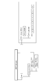
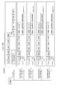
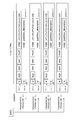
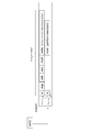
- MP4 stream (track) in, when making a tile stream into a single stream structure. It is a figure which shows the structural example of the transport stream in, when making a tile stream into a single stream structure. It is a figure which shows the structural example of the MMT stream in, when making a tile stream into a single stream structure. It is a figure which shows roughly another example of MP4 stream (track) in, when encoding using the tile function which makes each partition a tile. It is a figure which shows roughly another example of MP4 stream (track) in, when each partition is encoded separately. It is a figure which shows roughly an example of MP4 stream (track) in, when making a tile stream into a single stream structure.
- Embodiment> [Overview of MPEG-DASH-based stream delivery system] First, an overview of an MPEG-DASH-based stream delivery system to which the present technology can be applied will be described.
- FIG. 1 shows an example of the configuration of an MPEG-DASH-based stream delivery system 30.
- a media stream and an MPD (Media Presentation Description) file are transmitted through a communication network transmission line (communication transmission line).
- the stream delivery system 30 includes a DASH stream file server 31 and a DASH MPD server 32, N service receivers 33-1, 33-2, ..., 33-N, and a CDN (Content Delivery Network) 34. It is connected via the connection.
- DASH stream file server 31 generates a stream segment of DASH specification (hereinafter referred to as “DASH segment” as appropriate) based on media data (video data, audio data, subtitle data, etc.) of predetermined content, and receives service Sends segments in response to HTTP requests from machines.
- the DASH stream file server 31 may be a server dedicated to streaming, or may be shared by a web server.
- the DASH stream file server 31 responds to the request of the segment of the predetermined stream sent from the service receiver 33 (33-1, 33-2, ..., 33-N) via the CDN 34, The segments of the stream are sent via the CDN 34 to the requesting receiver.
- the service receiver 33 refers to the value of the rate described in the Media Presentation Description (MPD) file and selects the stream of the optimal rate according to the state of the network environment in which the client is located. And make a request.
- MPD Media Presentation Description
- the DASH MPD server 32 is a server that generates an MPD file for acquiring a DASH segment generated in the DASH stream file server 31. Based on the content metadata from the content management server (not shown) and the address (url) of the segment generated in the DASH stream file server 31, an MPD file is generated.
- the DASH stream file server 31 and the DASH MPD server 32 may be physically the same.
- the attributes of each stream such as video and audio are described using an element called Representation (Representation).
- Representation For example, in the MPD file, for each of a plurality of video data streams having different rates, the representation is divided and the respective rates are described.
- the service receiver 33 can select the optimal stream according to the state of the network environment in which the service receiver 33 is placed, as described above, with reference to the value of the rate.
- FIG. 2 shows an example of the relationship between structures arranged hierarchically in the MPD file.
- the media presentation Media Presentation
- AdaptationSet a plurality of adaptation sets
- Each adaptation set depends on differences in media types such as video and audio, differences in language even in the same media type, and differences in viewpoints.
- AdaptationSet a plurality of representations (Representations) exist in the adaptation set. Each representation depends on stream attributes, such as differences in rates.
- the representation includes segment info.
- this segment info as shown in FIG. 2 (e), an initialization segment and a plurality of media segments (Media) in which information for each segment into which the period is further divided are described Segment) exists.
- Media media segments
- address (url) information and the like for actually acquiring segment data such as video and audio.
- streams can be freely switched between a plurality of representations included in the adaptation set. As a result, it is possible to select an optimal rate stream according to the state of the network environment on the receiving side, and to enable uninterrupted video delivery.
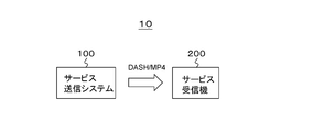
- FIG. 3 shows a configuration example of the transmission and reception system 10 according to the embodiment.
- the transmission / reception system 10 is configured of a service transmission system 100 and a service receiver 200.
- the service transmission system 100 corresponds to the DASH stream file server 31 and the DASH MPD server 32 of the stream distribution system 30 shown in FIG. 1 described above.
- the service receiver 200 corresponds to the service receivers 33 (33-1, 33-2,..., 33-N) of the stream distribution system 30 shown in FIG. 1 described above.
- the service transmission system 100 transmits DASH / MP4, that is, an MPD file as a metafile, and an MP4 (ISOBMFF) stream including media streams (media segments) such as video and audio, through a communication network channel (see FIG. 1). ,Send.
- DASH / MP4 that is, an MPD file as a metafile
- ISOBMFF MP4
- the MP4 stream includes a coded stream (coded image data) corresponding to a divided area (partition) obtained by dividing the wide viewing angle image.
- the wide-viewing-angle image is a projection image obtained by cutting a part or all of a spherical capture image and plane packing, but is not limited thereto.
- the encoded stream corresponding to each divided area of the wide view angle image can be obtained, for example, by individually coding each divided area of the wide view angle image, or each divided area of the wide view angle image is used as a tile. It is obtained by performing encoding using a tile function.
- the coded stream is hierarchically coded to facilitate temporal partial decoding at the receiver side.
- the coded stream corresponding to each divided area of the wide viewing angle image is transmitted together with the information on the number of pixels and the frame rate of each divided area.
- a descriptor having the number of pixels of the divided area and the frame rate is included in MP4, which is a container including the encoded stream of each divided area.
- the coded stream corresponding to the requested divided area is transmitted.
- the transmission band it is possible to prevent the transmission band from being unnecessarily wide, and efficient use of the transmission band becomes possible.
- the service receiver 200 receives the above-mentioned MP4 (ISOBMFF) stream transmitted from the service transmission system 100 through the communication network channel (see FIG. 1).
- the service receiver 200 acquires, from the MPD file, meta information on the encoded stream corresponding to each divided area of the wide-viewing angle image.
- the service receiver 200 requests the service transmission system (distribution server) 100 to transmit a predetermined number of encoded streams corresponding to the display area, receives and decodes the predetermined encoded stream, and displays image data of the display area. Get the image and display.
- a predetermined number of values are calculated based on the decoding capability and the information on the number of pixels and the frame rate respectively associated with the encoded stream corresponding to each divided area of the wide viewing angle image. It is required to be decodable as much as possible. As a result, it is possible to reduce the frequency of switching of the distribution encoded stream accompanying movement of the display area due to user operation or operation as much as possible, and the display performance in VR reproduction is improved.
- the decoding method when it is predicted that the display area goes out of the decoding range, the decoding method is switched from temporal full decoding to temporal partial decoding, and thereafter, If it is predicted that the display area converges within the decoding range, the decoding method is switched from temporal partial decoding to temporal full decoding.
- the number of decodable divided areas can be increased, the frequency of switching of the delivery encoded stream with respect to movement of the display area different from prediction can be reduced, and display in VR reproduction Performance is further improved.
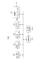
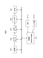
- FIG. 4 schematically shows an example of the overall configuration of the transmission / reception system 10.
- the service transmission system 100 includes a 360 ° image capture unit 102, a plane packing unit 103, a video encoder 104, a container encoder 105, and a storage 106.
- the 360 ° image capture unit 102 captures an object with a predetermined number of cameras, and obtains image data of a wide view angle image, in this embodiment, a spherical capture image (360 ° VR image).
- a spherical capture image 360 ° VR image
- the 360 ° image capture unit 102 performs imaging in a back-to-back method, and as a spherical capture image, each has a viewing angle of 180 ° or more imaged using a fisheye lens. Obtain front and back images of a wide viewing angle.
- the plane packing unit 103 cuts out part or all of the spherical captured image obtained by the 360 ° image capturing unit 102 and plane packing to obtain a projection picture.
- a projection picture In this case, as the format type of the projection image, for example, an equal rectangle, a cross-cubic or the like is selected.
- the plane packing unit 103 performs scaling on the projection image as necessary to obtain a projection image of a predetermined resolution.
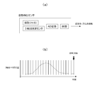
- FIG. 5A shows an example of a front image and a rear image of an ultra-wide viewing angle as a spherical capture image obtained by the 360 ° image capture unit 102.
- FIG. 5B illustrates an example of a projection image obtained by the plane packing unit 103. This example is an example in the case where the format type of the projection image is an exact rectangle. This example is an example of cutting out at the latitude shown by the broken line in each image shown in FIG. 5 (a).
- FIG. 5C shows another example of the projection image obtained by the plane packing unit 103. This example is an example in the case where the format type of the projection image is cross cubic.
- the video encoder 104 performs encoding such as MPEG4-AVC or HEVC on the image data of the projection image from the plane packing unit 103 to obtain encoded image data, and this encoding is performed. Generate a coded stream containing image data. In this case, the video encoder 104 divides the projection image into a plurality of partitions (division areas), and obtains a coded stream corresponding to each partition.
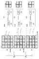
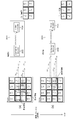
- FIG. 6A shows an example of division in the case where the format type of the projection image is an equi-rectangler.
- FIG. 6B shows an example of division in the case where the format type of the projection image is cross cubic. Note that the method of dividing the projection image is not limited to this example, and, for example, the sizes of all the partitions may not be the same.
- the video encoder 104 encodes, for example, each partition individually or collectively encodes the entire projection image in order to obtain an encoded stream corresponding to each partition of the projection image. Coding is performed using the tile function to be a tile. As a result, on the receiving side, it becomes possible to decode the coded stream corresponding to each partition independently.
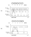
- FIG. 7A shows an example of hierarchical coding.
- the vertical axis shows the hierarchy.
- the horizontal axis indicates the display order (POC: picture order of composition), the left side is the display time before, and the right side is the display time after.
- Each rectangular frame indicates a picture, and a number indicates a display order.
- Solid arrows indicate reference relationships of pictures in encoding.
- each picture is classified into three layers of sub layer 2 (Sub layer 2), sub layer 1 (Sub layer 1) and full layer (Full Layer), and coding is applied to image data of pictures of each layer.
- the picture of "0" corresponds to the I picture
- the picture of "1" corresponds to the b picture
- the picture of "2” corresponds to the B picture
- the picture of "3" corresponds to the b picture
- And "4" correspond to P pictures.
- sublayer 1 In this hierarchical coding, only sublayer 2 can be selectively decoded, and in that case, image data of a frame rate of 1 ⁇ 4 can be obtained. Further, in this hierarchical coding, sublayer 1 and sublayer 2 can be selectively decoded, and in this case, image data of a frame rate of 1/2 can be obtained. Furthermore, in this hierarchical coding, all of the sublayer 1, sublayer 2 and full layer can be decoded, in which case full frame rate image data can be obtained.
- FIG.7 (b) has shown another example of hierarchical encoding.
- the vertical axis shows the hierarchy.
- the horizontal axis indicates the display order (POC: picture order of composition), the left side is the display time before, and the right side is the display time after.
- Each rectangular frame indicates a picture, and a number indicates a display order.
- Solid arrows indicate reference relationships of pictures in encoding.
- This example is an example in which each picture is classified into two layers of sub layer 1 (Sub layer 1) and full layer (Full Layer), and coding is performed on image data of pictures of each layer.
- Sub layer 1 sub layer 1
- Full Layer Full Layer
- the picture of “0” corresponds to the I picture
- the pictures of “1” to “3” correspond to the b picture
- the picture of “4” corresponds to the P picture.
- sublayer 1 In this hierarchical coding, only sublayer 1 can be selectively decoded, and in that case, image data of a frame rate of 1 ⁇ 4 can be obtained. Also, in this hierarchical coding, all of the sublayer 1 and the full layer can be decoded, and in that case, full frame rate image data can be obtained.
- the container encoder 105 generates a container including the encoded stream generated by the video encoder 104, here, an MP4 stream as a delivery stream.
- a plurality of MP4 streams each including a coded stream corresponding to each partition are generated.
- the container encoder 105 When encoding is performed using a tile function in which each partition is a tile, the container encoder 105 includes sublayer information and the like in addition to a plurality of MP4 streams each including the encoded stream corresponding to each partition. Generate a base MP4 stream (base container) including parameter sets such as SPS.
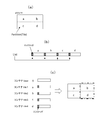
- a tile is capable of dividing a picture in horizontal and vertical directions and encoding / decoding each independently. Since the tile can refresh intra prediction, loop filter and entropy coding in a picture, it is possible to independently encode / decode each region divided as a tile.
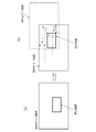
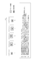
- FIG. 8A shows an example in which a picture is divided into four in total of vertical and horizontal divisions, and each partition is encoded as a tile.
- FIG. 8B a list of byte positions of the first data of each tile is described in the slice header for the tile-partitioned a, b, c, d partitions (tiles). Independent decoding is possible.
- the receiving side can reconstruct the original picture. For example, as shown in FIG. 8C, when the encoded stream of the partitions b and d enclosed by a rectangular frame of a dashed dotted line is decoded, the partitions (tiles) of the partitions b and d can be displayed.
- the sub-layer information is arranged in one SPS in a picture. Therefore, meta information such as a parameter set is stored in a tile-based MP4 stream (tile-based container). Then, in the MP4 stream (tile container) of each partition, a coded stream corresponding to each partition is stored as slice information.
- the container encoder 105 inserts information on the number of pixels of the partition and the frame rate in the layer of the container.
- a partition descriptor (partition_descriptor) is inserted in an initialization segment (IS) of the MP4 stream.
- IS initialization segment
- a plurality of partition descriptors may be inserted in units of pictures as the maximum frequency.
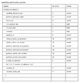
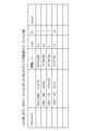
- FIG. 9 shows an example structure (Syntax) of the partition descriptor.
- FIG. 10 also shows the contents (Semantics) of the main information in the structural example.
- An 8-bit field of "partition_descriptor_tag” indicates a descriptor type, which indicates that it is a partition descriptor.
- the 8-bit field "partition_descriptor_length” indicates the length (size) of the descriptor, and indicates the number of subsequent bytes as the length of the descriptor.
- the 8-bit field "frame_rate” indicates the frame rate (full frame rate) of the partition (divided picture).
- a 1-bit field of "tile_partition_flag” indicates whether or not the picture is divided in a tile system. For example, “1” indicates that the picture is divided in the tile system, and “0” indicates that the picture is not divided in the tile system.
- a 1-bit field of "tile_base_flag” indicates whether it is a base container or not in the case of tile system. For example, “1” indicates that it is a base container, and "0” indicates that it is a container other than the base container.
- An 8-bit field of "partition_ID” indicates the ID of the partition.
- the 16-bit field “whole_picture_size_horizontal” indicates the number of horizontal pixels in the entire picture.
- the 16-bit field “whole_picture_size_vertical” indicates the number of vertical pixels in the entire picture.
- the 16-bit field "partition_horizontal_start_position” indicates the horizontal start pixel position of the partition.
- the 16-bit field “partition_horizontal_end_position” indicates the horizontal end pixel position of the partition.
- the 16-bit field “partition_vertical_start_position” indicates the vertical start pixel position of the partition.
- the 16-bit field “partition_vertical_end_position” indicates the vertical end pixel position of the partition.
- An 8-bit field of "number_of_sublayers” indicates the number of sublayers in hierarchical coding of partitions.
- the 8-bit field of "sublayer_id” and the 8-bit field of "sublayer_frame_rate” are repeated in the for loop by the number of sublayers.
- the field of “sublayer_id” indicates the sublayer ID of the partition, and the field of “sublayer_frame_rate” indicates the frame rate of the sublayer of the partition.
- the storage 106 temporarily accumulates the MP4 stream of each partition generated by the container encoder 105. In the case of division by tile method, the storage 106 also accumulates tile-based MP4 streams. Among the MP4 streams accumulated in this way, the MP4 stream of the partition for which the transmission request has been made is transmitted to the service receiver 200. In addition, when it is divided by the tile method, the MP4 stream of the base is also simultaneously transmitted.
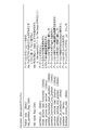
- FIG. 11 shows an example of description of an MPD file corresponding to tile-based MP4 stream (tile-based container).
- this MPD file there is an adaptation set (AdaptationSet) corresponding to one MP4 stream (track) as a tile-based container.
- AdaptationSet adaptation set
- AdaptationSet the video stream of which is provided in an MP4 file structure, indicating the presence of a HEVC encoded video stream (encoded image data).
- a representation (Representation) corresponding to the video stream exists.
- the rate and the type of codec are indicated, and it is further indicated that the level "0" is given as tag information.
- the location destination of this MP4 stream is indicated as "videostream VR.
- Mp 4" by the description of " ⁇ Base URL> video stream VR.
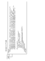
- FIG. 12 shows an example of description of an MPD file corresponding to the MP4 stream of each partition.
- an adaptation set AdaptationSet
- tracks an adaptation set corresponding to each of a plurality of MP4 streams (tracks) exists.
- AdaptationSets two adaptation sets
- the first adaptation set will be described, and the other adaptation sets are similar, so the description will be omitted.
- the video stream is provided in an MP4 file structure, indicating the presence of a HEVC encoded video stream (encoded image data).
- a representation (Representation) corresponding to the video stream exists.
- the rate and the type of codec are indicated, and it is further indicated that the level "0" is given as tag information.
- the location destination of this MP4 stream is indicated as "videostream VR0.mp4" by the description of " ⁇ BaseURL> videostreamVR0.mp4 ⁇ / BaseURL>”.
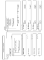
- FIG. 13 schematically shows an MP4 stream (track) when encoding is performed using a tile function in which each partition is a tile.
- each partition is a tile.
- each random access period starts from an initialization segment (IS: initialization segment), and “styp”, “sidx (Segment index box)”, “ssix (Sub-segment index) It is configured such that boxes “box”, “moof (Movie fragment box)”, and “mdat (Media data box)” are continued.
- the initialization segment (IS) has a box structure based on ISO Base Media File Format (ISOBMFF).
- ISOBMFF ISO Base Media File Format
- a partition descriptor (see FIG. 9) is inserted in this initialization segment (IS).
- the MP4 stream (tile container) of the first to fourth partitions “partition ID” is 1 to 4.
- Segment type information is entered in the "styp” box.
- range information of each track (track) is entered, the position of "moof” / “mdat” is shown, and the position of each sample (picture) in “mdat” is also shown.
- the “ssix” box contains track classification information, and I / P / B type classification.
- the "moof” box contains control information.
- VPS ",” SPS ",” PPS ",” PSEI ", and” SSEI "NAL units are arranged.
- NAL unit of" SLICE "having the encoded image data of each partition is arranged.
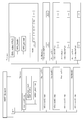
- FIG. 14 schematically shows an MP4 stream (track) in the case where each partition is individually encoded.
- each partition there are four partitions of MP4 streams.
- each random access period starts from an initialization segment (IS: initialization segment), and “styp”, “sidx (Segment index box)”, “ssix (Sub-segment index) It is configured such that boxes “box”, “moof (Movie fragment box)”, and “mdat (Media data box)” are continued.
- the initialization segment (IS) has a box structure based on ISO Base Media File Format (ISOBMFF).
- ISOBMFF ISO Base Media File Format
- a partition descriptor (see FIG. 9) is inserted in this initialization segment (IS).
- the “partition ID” is 1 to 4.
- Segment type information is entered in the "styp” box.
- range information of each track (track) is entered, the position of "moof” / “mdat” is shown, and the position of each sample (picture) in “mdat” is also shown.
- the “ssix” box contains track classification information, and I / P / B type classification.
- the "moof” box contains control information.
- VPS ",” SPS “,” PPS “,” PSEI “,” SLEI ", and” SSEI "NAL units are arranged.
- the service receiver 200 includes a container decoder 203, a video decoder 204, a renderer 205, and a transmission request unit 206.
- the transmission request unit 206 requests the service transmission system 100 to transmit an MP4 stream of a predetermined number of partitions corresponding to the display area among the partitions of the projection image.
- the predetermined number of values are set to the maximum or near decodable value based on the decoding capability and the information on the number of pixels in the coded stream of each partition of the projection image and the frame rate. Ru.
- the information on the number of pixels and the frame rate in the encoded stream of each partition can be acquired from the MPD file (see FIG. 12) previously received from the service transmission system 100.
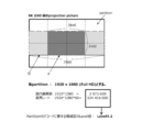
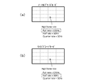
- FIG. 15 shows an example of dividing an 8K / 60 Hz grade projection image with a partition size of 1920 ⁇ 1080 (Full HD).
- the level value of complexity required to decode a partition is “Level 4.1”.
- the service receiver 200 can decode up to four partitions.
- the four partitions indicated by the arrow P indicate examples of partitions corresponding to the display area selected in this case.
- the service receiver 200 can decode up to eight partitions.
- the eight partitions indicated by the arrow Q show an example of partitions corresponding to the display area selected in this case.
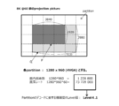
- FIG. 16 shows an example of dividing an 8K / 60 Hz grade projection image with a partition size of 1280 ⁇ 960 (4 VGA).
- the level value of complexity required to decode a partition is “Level 4.1”.
- the service receiver 200 can decode up to seven partitions. Six partitions indicated by an arrow P indicate examples of partitions corresponding to the display area selected in this case.
- the service receiver 200 has a “Level 5.2” decoder for decoding at 4K / 120 Hz
- the Luma maximum number of pixels in a plane is 8912896
- the service receiver 200 can decode up to 14 partitions. Twelve partitions indicated by an arrow Q show an example of a partition corresponding to the display area selected in this case.
- FIG. 17 shows an example of dividing a projection image exceeding 8K / 60 Hz with a partition size of 1280 ⁇ 960 (4 VGA).
- the level value of complexity required to decode a partition is “Level 4.1”.
- the service receiver 200 can decode up to seven partitions. Seven partitions indicated by an arrow P indicate examples of partitions corresponding to the display area selected in this case.
- the service receiver 200 has a “Level 5.2” decoder for decoding at 4K / 120 Hz
- the Luma maximum number of pixels in a plane is 8912896
- the service receiver 200 can decode up to 14 partitions. Fourteen partitions indicated by an arrow Q indicate an example of partitions corresponding to the display area selected in this case.
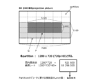
- FIG. 18 shows an example of dividing an 8K / 60 Hz grade projection image with a partition size of 1280 ⁇ 720 (720 p HD).
- the level value of the complexity required to decode the partition is "Level 4".
- the service receiver 200 can decode up to nine partitions. Eight partitions indicated by an arrow P indicate examples of partitions corresponding to the display area selected in this case.
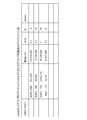
- FIG. 19 collectively shows the decodable maximum number of partitions according to the partition size in the “Level 5.1” decoder.
- the partition size is 1920 ⁇ 1080 (Full HD)
- the maximum pixel count that can be processed per second by the decoder is 534773760
- the pixel rate of the partition is 124416000 (equivalent to Level 4.1)
- the maximum decodable The number of partitions is four.
- the partition size is 1280 ⁇ 960 (4 VGA)
- the maximum pixel count that can be processed per second of the decoder is 534773760
- the pixel rate of the partition is 73728000 (equivalent to Level 4.1) and can be decoded
- the maximum number of partitions is seven.
- the maximum pixel count that can be processed per second by the decoder is 534773760, while the pixel rate of the partition is 55296000 (equivalent to Level 4), and the maximum decodable The number of partitions is nine.
- the partition size is 960 ⁇ 540 (QHD)
- the maximum pixel count that can be processed per second by the decoder is 534773760, while the pixel rate of the partition is 33177600 (equivalent to Level 3.1), which allows decoding
- the maximum number of partitions is 16.
- FIG. 20 collectively shows the decodable maximum number of partitions according to the partition size in the “Level 5.2” decoder.
- the partition size is 1920 ⁇ 1080 (Full HD)
- the maximum pixel count that can be processed per second of the decoder is 1069547520
- the pixel rate of the partition is 124416000 (equivalent to Level 4.1)
- the maximum decodable The number of partitions is eight.
- the partition size is 1280 ⁇ 960 (4 VGA)
- the maximum pixel count that can be processed per second of the decoder is 1069547520, while the pixel rate of the partition is 73728000 (equivalent to Level 4.1), so that decoding is possible
- the maximum number of partitions is 14.
- the maximum pixel count that can be processed per second by the decoder is 1069547520, while the pixel rate of the partition is 55296000 (equivalent to Level 4), and the maximum decodable The number of partitions is 19. Also, when the partition size is 960 ⁇ 540 (QHD), the maximum pixel count that can be processed per second of the decoder is 1069547520, while the pixel rate of the partition is 33177600 (equivalent to Level 3.1), which allows decoding The maximum number of partitions is 32.
- the transmission request unit 206 may be provided with a table as shown in FIG. 19 or 20, and may refer to this table to obtain the maximum value (the maximum number of decodable partitions).
- the transmission request unit 206 determines the number of partitions that can be decoded or the maximum number of decodable values as a partition corresponding to the display area that requests the service transmission system 100 to transmit based on the pixel rate of each partition. Choose
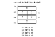
- FIG. 21 shows the case where the number of pixels in each partition is not uniform.
- ID1, ID2, ID3, ID4, ID5 and ID6 are respectively (H0, V0), (H0, V1), (H1, V1), (H0, V2), (H1, V2), (H0, V3) Indicates the partition ID of the partition in the position of.
- the pixel rates of the partitions whose partition IDs are ID1, ID2, ID3, ID4, ID5, and ID6 are R1, R2, R3, R4, R5, R5, and R6, respectively. If the decoder of the service receiver 200 is “Level X” and the pixel rate corresponding to it is D1, for example, if R1 + R2 + R3 ⁇ D1, then it is possible to decode the partitions with partition ID ID1, ID2, and ID3. It can be said.
- the container decoder 203 extracts the coded stream of each partition from the MP4 stream of the predetermined number of partitions corresponding to the display area sent from the service transmission system 100 and sends it to the video decoder 204.
- the container decoder 203 also sends to the video decoder 204 a coded stream including parameter set information and the like included in the tile-based MP4 stream.
- the video decoder 204 decodes the coded stream of a predetermined number of partitions corresponding to the display area to obtain image data of the predetermined number of partitions corresponding to the display area.
- the renderer 205 performs rendering processing on the image data of the predetermined number of partitions obtained in this manner, and obtains a rendered image (image data) corresponding to the display area.
- the movement of the display area is controlled according to sensor information, pointing information, voice UI information, and the like.
- sensor information pointing information
- voice UI information voice UI information
- the display area is controlled based on information on the direction and amount of movement obtained by a gyro sensor or the like mounted on the HMD with movement of the user's neck. Is controlled.
- the display panel is used as the display device, the movement of the display area is controlled based on the pointing information by the user operation or the voice UI information of the user.
- FIG. 22 shows the case where an HMD is used as a display device.
- the display area observed by the HMD becomes a diagram as shown in FIG.
- the movement proceeds as P1 ' ⁇ P2' ⁇ P3 '.
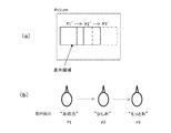
- FIG. 23 shows a case where a display panel such as a TV is used as a display device.
- the voice instruction is changed as P1.fwdarw.P2.fwdarw.P3
- the display area displayed on the display panel is as shown in FIG. 23 (a). It moves as P1 ′ ⁇ P2 ′ ⁇ P3 ′.
- the transmission request unit 206 determines switching of a set of MP4 streams of a predetermined number of partitions corresponding to the display area, in order to set the display area as a decoding range. Request the service transmission system 100 to transmit a new set (delivery stream set).
- FIG. 24 illustrates an example of switching of a delivery stream set accompanying movement of a display area.
- This example is an example in which MP4 streams of four partitions corresponding to the display area are transmitted (distributed).
- the partitions corresponding to the display area are (H0, V1), (H1, V1), (H0, V2), and (H1, V2).
- Partitions, and MP4 streams of these partitions are transmitted, for example, in the order of (1) ⁇ (2) ⁇ (5) ⁇ (6).
- the coded stream is extracted from the MP4 stream of these partitions and decoded by the video decoder 204. That is, the decoding range in this case is a partition at the positions of (H0, V1), (H1, V1), (H0, V2), and (H1, V2).
- the partitions corresponding to the display area are (H1, V1), (H2, V1), (H1, V2), (H2, V2) There will be 4 partitions in the position of. Therefore, switching of the delivery stream set is performed, and the MP4 streams of these partitions are transmitted in the order of (2) ⁇ (3) ⁇ (6) ⁇ (7), for example.
- the coded stream is extracted from the MP4 stream of these partitions and decoded by the video decoder 204. That is, the decoding range in this case is a partition at the positions of (H1, V1), (H2, V1), (H1, V2), and (H2, V2).
- the partitions corresponding to the display area are (H2, V1), (H3, V1), (H2, V2), (H3, V2) There will be 4 partitions in the position of. Therefore, switching of the delivery stream set is performed, and the MP4 streams of these partitions are transmitted, for example, in the order of (3) ⁇ (4) ⁇ (7) ⁇ (8).
- the coded stream is extracted from the MP4 stream of these partitions and decoded by the video decoder 204. That is, the decoding range in this case is a partition at the positions of (H2, V1), (H3, V1), (H2, V2), and (H3, V2).
- FIG. 25 illustrates another example of switching of a delivery stream set as the display area moves.
- This example is an example in which MP4 streams of six partitions corresponding to the display area are transmitted (distributed).
- the partitions corresponding to the display area are (H0, V1), (H1, V1), (H2, V1), (H0, V2), For example, (1) ⁇ (2) ⁇ (3) ⁇ (5) ⁇ (5) ⁇ (6) ⁇ (7) MP1 streams of H1 and V2) and (H2 and V2) are obtained. Sent in the order of).
- the coded stream is extracted from the MP4 stream of these partitions and decoded by the video decoder 204. That is, the decoding range in this case is a partition at the positions of (H0, V1), (H1, V1), (H2, V1), (H0, V2), (H1, V2), (H2, V2) .
- the partitions corresponding to the display area are (H0, V1), (H1, V1), (H2, V1), (H0, V1)
- the six partitions remain at V2), (H1, V2), (H2, V2). Therefore, there is no switching of the delivery stream set, and the MP4 streams of these partitions are transmitted, for example, in the order of (1) ⁇ (2) ⁇ (3) ⁇ (5) ⁇ (6) ⁇ (7).
- the coded stream is extracted from the MP4 stream of these partitions and decoded by the video decoder 204. That is, the decoding range in this case is a partition at the positions of (H1, V1), (H2, V1), (H1, V2), and (H2, V2).
- the partitions corresponding to the display area are (H1, V1), (H2, V1), (H3, V1), (H1, V2) , (H2, V2), (H3, V2) positions of six partitions. Therefore, switching of the delivery stream set is performed, and the MP4 streams of these partitions are transmitted, for example, in the order of (2) ⁇ (3) ⁇ (4) ⁇ (6) ⁇ (7) ⁇ (8).
- the coded stream is extracted from the MP4 stream of these partitions and decoded by the video decoder 204. That is, the decoding range in this case is a partition at the positions of (H1, V1), (H2, V1), (H3, V1), (H1, V2), (H2, V2), (H3, V2) .
- the switching frequency of the delivery stream set accompanying the movement of the display area is suppressed low. It is possible to improve the display performance in VR reproduction.
- the transmission request unit 206 determines to switch the distribution stream set and requests the service transmission system 100 to transmit a new distribution stream set. .
- this prediction is performed by a control unit that controls the operation of each unit of the service receiver 200.
- FIG. 26A shows a state in which the display area falls within the current decoding range.
- FIG. 26B shows a state in which the display area has moved in the direction indicated by the broken line arrow m from that state.
- a solid arrow n indicates the movement speed and movement direction of the display area detected in the last few frames.
- the transmission request unit 206 determines a new predetermined number of partitions based on the movement prediction of the display area so as to obtain a new decoding range in which the display area is included, and a new MP4 stream is generated.
- the service transmission system 100 is requested to transmit various distribution stream sets.
- FIG. 27 shows how the decoding range is switched when the display area moves.
- solid arrows indicate the predicted movement direction of the display area
- broken arrows indicate the actual movement direction of the display area.
- FIG. 27B shows the case where the delivery stream set is switched based on the movement prediction direction of the display area from the state of FIG. 27A, and the actual movement direction of the display area is the movement prediction direction It shows the state in which it was fitted. In this case, there is no problem because the display area falls within the decoding range.
- FIG. 27C shows the case where the delivery stream set is switched based on the movement prediction direction of the display area from the state of FIG. 27B, and the actual movement direction of the display area is movement prediction. It shows the state when it matches the direction. In this case, there is no problem because the display area falls within the decoding range.
- FIG. 27D shows the case where the delivery stream set is switched based on the movement prediction direction of the display area from the state of FIG. 27B, and the actual movement direction of the display area is the movement prediction direction. It shows the situation when it did not fit. In this case, since the display area does not fall within the decoding range, it is necessary to switch the stream set again and change to the decoding range indicated by hatching so that the display area falls within the decoding range. It becomes. In such a case, there is a possibility that the display may be temporarily frozen due to a time lag before switching.
- the number of partitions is increased so that the display area after movement is positioned at the center of the decoding range.
- the normal decode mode is changed to the wide decode mode.
- temporal partial decoding ie, a sub-layer, is performed on a part or all of the encoded stream of a predetermined number of partitions so that the predetermined number of partitions can be decoded in the wide decoding mode. Decoding is performed.
- FIG. 28 shows how the decoding range is switched when the display area moves.
- solid arrows indicate the predicted movement direction of the display area
- broken arrows indicate the actual movement direction of the display area.
- FIG. 28 (b) is the case where the delivery stream set is switched based on the movement prediction direction of the display area from the state of FIG. 28 (a), and the actual movement direction of the display area is the movement prediction direction. It shows the state in which it was fitted. In this case, the number of partitions is increased to widen the decoding range on the premise that temporal partial decoding is performed. In this case, the display area falls within the decoding range.
- FIG.28 (c) has shown the state which the display area moved from the state of FIG.28 (b). In this case, a state is shown in which the actual movement direction of the display area matches the movement prediction direction. In this case, since the decoding range is expanded, the movement of the display area is the movement within the decoding range, and therefore, the switching of the delivery stream set is not performed.
- FIG. 28 (d) shows a state in which the display area has moved from the state shown in FIG. 28 (b). In this case, a state is shown in which the actual movement direction of the display area does not match the movement prediction direction. In this case, since the decoding range is expanded, the movement of the display area is the movement within the decoding range, and therefore, the switching of the delivery stream set is not performed.
- FIG. 29 shows the frame rate of each partition in the case where the video coding is tile compatible. In this case, the frame rate and layering of hierarchical coding are the same for all partitions.
- FIG. 29A shows that decoding processing at a full frame rate is performed in the normal decoding mode.
- FIG. 29 (b) shows that temporal partial decoding, for example, decoding at half rate is performed in the wide decoding mode.
- FIG. 30 shows the frame rate of partitions in the case where video coding is encoded into independent streams for each partition.
- the frame rate and the layering of hierarchical coding may not be the same for all partitions, since different coding is possible for each partition.
- the central six partitions are set to 120 Hz at the high frame rate, while the peripheral ten partitions are set to 60 Hz at the low frame rate.
- FIG. 30A shows that the decoding process is performed at the full frame rate in the normal decoding mode.
- FIG. 30 (b) shows that temporal partial decoding, for example, decoding at half rate is performed in the wide decoding mode.
- FIG. 30C in the wide decode mode, the decoding process at the full frame rate is performed in the central six partitions, and the decoding process is performed at the quarter rate in the peripheral ten partitions. It shows.
- the transmission request unit 206 requests the service transmission system 100 to stop transmission other than the predetermined number of partitions in the normal decode mode.
- the convergence prediction is performed by observing a change in movement of the display area. Although not shown in FIG. 4, this prediction is performed by a control unit that controls the operation of each unit of the service receiver 200. For example, in the case where an HMD is used as a display device, it is possible to determine the convergence based on attitude angle / azimuth information obtained from the attitude detection sensor mounted on the HMD.
- FIG. 31A schematically shows the configuration of the posture detection sensor.
- the attitude detection sensor includes a vibrating gyroscope and a three-axis acceleration sensor. Variation of the position of each of the pitch, roll, and yaw three axes by the vibration gyro, and the acceleration applied to each of the X, Y, and Z axes by the three-axis acceleration sensor, finally the attitude angle (roll angle, pitch angle), and azimuth Corner information is output.
- FIG. 32 shows an example of mode change control.
- the normal decode mode is set.
- the normal decode mode is switched to the wide decode mode accordingly.
- T3 movement of the display area is detected, but since the position of the display area is within the wide decoding range at T2, the decoding range is not updated.
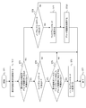
- the flowchart in FIG. 33 illustrates an example of control processing of decoding range change and mode change in the control unit of the service receiver 200.
- the control unit executes this control process, for example, in a video frame cycle.
- control unit starts processing in step ST1.
- step ST2 the control unit detects the movement of the display area.
- the movement of the display area is detected based on, for example, sensor information, pointing information or voice UI information.
- step ST3 the control unit determines whether the display area is predicted to be out of the current decoding range. This determination is made based on whether the display area satisfies the position condition and the movement condition as described above. When the display area is not predicted to be out of the current decoding range, the control unit determines whether or not the wide decoding mode is in step ST4. When in the wide decode mode, the control unit proceeds to the process of step ST5.
- step ST5 the control unit determines whether the display area is predicted to converge within the decoding range corresponding to the normal decoding mode. This determination is made by observing the change in movement of the display area including the past several frames, as described above. When it is predicted that convergence will occur, the control unit changes from the wide decode mode to the normal decode mode in step ST6.
- step ST6 the control unit ends the process in step ST7.
- the control unit proceeds to step ST7 and ends the process.
- the control unit determines in step ST8 whether or not it is in the normal decoding mode.
- the control unit changes to the wide decoding mode in step ST9, and changes the decoding range in step ST10.
- the server service transmission system 100
- the server is requested to set (delivery stream set) of MP4 streams of a predetermined number of partitions corresponding to the display area and according to the decoding mode. You will receive a stream set.
- step ST10 the control unit proceeds to step ST7 and ends the process. Further, when in the wide decoding mode in step ST8, the control unit proceeds to step ST9 to change the decoding range, and thereafter ends the processing in step ST7.
- FIG. 34 shows a configuration example of the service transmission system 100.
- the service transmission system 100 includes a communication unit 107 including a control unit 101, a user operation unit 101a, a 360 ° image capture unit 102, a plane packing unit 103, a video encoder 104, a container encoder 105, and a storage 106.
- a communication unit 107 including a control unit 101, a user operation unit 101a, a 360 ° image capture unit 102, a plane packing unit 103, a video encoder 104, a container encoder 105, and a storage 106.
- the control unit 101 includes a CPU (Central Processing Unit), and controls the operation of each unit of the service transmission system 100 based on a control program.
- the user operation unit 101a is a keyboard, a mouse, a touch panel, a remote control, or the like for the user to perform various operations.
- the 360 ° image capture unit 102 captures an object with a predetermined number of cameras, and obtains image data of a spherical capture image (360 ° VR image). For example, the 360 ° image capture unit 102 performs imaging in a back-to-back method, and as a spherical capture image, each has a viewing angle of 180 ° or more imaged using a fisheye lens. Front and back images of a wide viewing angle are obtained (see FIG. 5 (a)).
- the plane packing unit 103 cuts out part or all of the spherical captured image obtained by the 360 ° image capturing unit 102 and plane packing to obtain a rectangular projection picture (Fig. 5 (b), (c). )reference).
- a rectangular projection picture Fig. 5 (b), (c). )reference.
- the format type of the projection image for example, an equal rectangle, a cross-cubic or the like is selected.
- the video encoder 104 performs encoding such as MPEG4-AVC or HEVC on the image data of the projection image from the plane packing unit 103 to obtain encoded image data, and includes the encoded image data. Generate a stream In this case, the video encoder 104 divides the projection image into a plurality of partitions (division areas), and obtains a coded stream corresponding to each partition.
- the video encoder 104 encodes each partition individually or collectively encodes the entire projection image, for example, in order to obtain a coded stream corresponding to each partition of the projection image. It encodes using the tile function which makes each partition a tile. As a result, on the receiving side, it becomes possible to decode the coded stream corresponding to each partition independently. Also, the video encoder 104 performs hierarchical coding on each partition (see FIGS. 7A and 7B). This hierarchical coding allows the receiver to easily perform temporal partial decoding.
- the container encoder 105 generates a container including the encoded stream generated by the video encoder 104, here, an MP4 stream as a delivery stream.
- an MP4 stream as a delivery stream.
- a plurality of MP4 streams respectively including coded streams corresponding to each partition are generated (see FIGS. 13 and 14).
- the container encoder 105 when encoding is performed using a tile function in which each partition is a tile, the container encoder 105 performs sub-layer information etc. in addition to a plurality of MP4 streams each including a coded stream corresponding to each partition.
- a base MP4 (base container) including parameter sets such as SPS is generated (see FIG. 13).
- the container encoder 105 inserts a partition descriptor (see FIG. 9) into the layer of the container, specifically, the initialization segment (IS) of MP4.
- the partition descriptor contains information such as the number of pixels of the partition and the frame rate.
- the storage 106 included in the communication unit 107 stores the MP4 stream of each partition generated by the container encoder 105. In the case of division by tile method, the storage 106 also accumulates tile-based MP4 streams. The storage 106 also stores, for example, an MPD file (see FIGS. 11 and 12) generated by the container decoder 105.
- the communication unit 107 receives the distribution request request from the service receiver 200, and transmits the MPD file to the service receiver 200 in response thereto.
- the service receiver 200 recognizes the configuration of the delivery stream from this MPD file.
- the communication unit 107 receives a distribution request (transmission request) of the MP4 stream corresponding to the predetermined number of partitions corresponding to the display area from the service receiver 200, and transmits the MP4 stream to the service receiver 200.
- the partition ID specifies a required partition.
- FIG. 35 shows a configuration example of the service receiver 200.
- the service receiver 200 includes a control unit 201, a UI unit 201a, a sensor unit 201b, a communication unit 202, a container decoder 202, a video decoder 204, a renderer 205, and a display unit 207.
- the control unit 201 includes a CPU (Central Processing Unit), and controls the operation of each unit of the service receiver 200 based on a control program.
- the UI unit 201a is for performing a user interface, and for example, a pointing device for the user to operate the movement of the display area or a microphone for the user to input voice for instructing the movement of the display area by voice. Etc. are included in this.
- the sensor unit 201 b includes various sensors for acquiring information on user status and environment, and includes, for example, an attitude detection sensor and the like mounted on a head mounted display (HMD).
- HMD head mounted display
- the communication unit 202 transmits a distribution request request to the service transmission system 100 under the control of the control unit 201, and correspondingly receives an MPD file (see FIGS. 11 and 12) from the service transmission system 100.
- the communication unit 202 sends this MPD file to the control unit 201.
- the control unit 201 recognizes the configuration of the delivery stream.
- the communication unit 202 transmits, to the service transmission system 100, a distribution request (transmission request) of the MP4 stream corresponding to the predetermined number of partitions corresponding to the display area.
- the service transmission system 100 receives an MP4 stream corresponding to a predetermined number of partitions.
- control unit 101 determines the direction of movement of the display area based on information on the direction and amount of movement obtained by a gyro sensor or the like mounted on the HMD, or based on pointing information by user operation or voice UI information of the user. And obtains speed information, and selects a predetermined number of partitions corresponding to the display area.
- control unit 101 can decode a predetermined number of values at or near the maximum that can be decoded based on the decoding capability and the information on the number of pixels in the encoded stream of each partition recognized from the MPD file and the frame rate.
- Set to The transmission request unit 206 illustrated in FIG. 4 is configured by the control unit 101.
- control unit 101 detects the movement of the display area and determines whether the display area is predicted to be out of the current decoding range, and when the wide decoding mode is in effect, the display area is in the normal decoding mode. It is determined whether or not convergence occurs within the corresponding decoding range, and control processing of changing the decoding range and changing the mode is performed (see FIG. 33).
- the container decoder 203 takes out the encoded stream of each partition from the MP4 stream of the predetermined number of partitions corresponding to the display area received by the communication unit 202 and sends it to the video decoder 204.
- division is performed in the tile method, not only the MP4 stream of the predetermined number of partitions corresponding to the display area, but also the tile-based MP4 stream is received by the communication unit 202, so that tile-based division is performed.
- the encoded stream including parameter set information and the like included in the MP4 stream is also sent to the video decoder 204.
- the container decoder 203 takes out the partition descriptor (see FIG. 9) inserted in the initialization segment (IS) of each MP4 stream, and sends it to the control unit 201.
- the control unit 201 acquires, from this descriptor, information on the number of pixels and frame rate in each partition, and hierarchical coding information.
- the video decoder 204 decodes the encoded stream of a predetermined number of partitions corresponding to the display area supplied from the container decoder 203 to obtain image data.
- the video decoder 204 when in the normal decoding mode, performs processing of temporal full decoding on the coded stream of a predetermined number of partitions, but in the wide decoding mode.
- the partial decoding process is performed temporally on a part or all of the encoded stream of the predetermined number of partitions, decoding of the predetermined number of partitions in the wide decoding mode is enabled (see FIGS. 29 and 30). ).
- the renderer 205 performs rendering processing on image data of a predetermined number of partitions obtained by the video decoder 204, and obtains a rendered image (image data) corresponding to the display area.
- the display unit 207 displays the rendered image (image data) obtained by the renderer 205.
- the display unit 207 is configured of, for example, an HMD (Head Mounted Display), a display panel, or the like.
- the service transmission system 100 is configured to calculate the coded stream corresponding to each partition (division area) of the wide view angle image (projection image) Send along with frame rate information. Therefore, on the receiving side, the number of partitions to be decoded corresponding to the display area is easily decodable on the basis of the decoding capability and the information on the number of pixels and frame rate of each partition of the wide viewing angle image. This can be set, the frequency of switching of the encoded stream accompanying the movement of the display area can be minimized, and the display performance in VR reproduction can be improved.
- the service receiver 200 calculates the number of partitions to be decoded corresponding to the display area based on the decoding capability and the information of the number of pixels of each partition and the frame rate. Therefore, the number of partitions to be decoded can be set up as easily as possible corresponding to the display area, the frequency of switching of the encoded stream accompanying the movement of the display area can be minimized, and the display performance in VR reproduction is improved. Is possible.
- the service receiver 200 predicts that the display area goes out of the decoding range, switches the decoding method to temporal partial decoding, and the display area converges within the decoding range.
- switch the decoding method to temporal full decoding In this case, the number of decodable divided areas can be increased by switching the decoding method to temporal partial decoding, and the frequency of switching of the coded stream with respect to movement of the display area different from prediction can be reduced. Further improvement of the display performance in
- the container encoder 105 of the service transmission system 100 shown in FIG. 4 generates a transport stream including an encoded stream of each partition of the projection image.
- the container encoder 105 inserts a partition descriptor (Partition_descriptor) (see FIG. 9) into the video elementary stream loop corresponding to each encoded stream of the program map table (PMT: Program Map Table). .
- Partition_descriptor partition descriptor
- FIG. 36 shows a configuration example of a transport stream in the case where video coding is tile-compatible.
- PES packets "video PES0" of the tile-based encoded stream identified by PID0.
- NAL units of “AUD”, “VPS”, “SPS”, “PPS”, “PSEI”, and “SSEI” are arranged.
- PES packets “video PES1” to “video PES4” of the coded streams of the first to fourth partitions (tiles) identified by PID1 to PID4 exist.
- NAL units of “AUD” and “SLICE” are arranged.
- video elementary stream loops corresponding to PES packets “video PES 0” to “video PES 4” exist in the PMT.
- information such as a stream type and a packet identifier (PID) is disposed corresponding to the encoded stream, and a descriptor that describes information related to the encoded stream is also disposed.
- This stream type is "0x24" indicating a video stream.
- a partition descriptor is inserted as one of the descriptors.
- the container encoder 104 of the service transmission system 100 shown in FIG. 4 generates an MMT stream (MMT stream) including a video stream.
- the container encoder 104 inserts a partition descriptor (see FIG. 9) into a video asset loop corresponding to the extended video stream of the MMT package table (MPT: MMT Package Table).
- FIG. 37 shows an exemplary configuration of an MMT stream in the case where video coding is tile-compatible.
- MPU packets "video MPU 0" of the tile-based encoded stream identified by ID0.
- NAL units of “AUD”, “VPS”, “SPS”, “PPS”, “PSEI”, and “SSEI” are arranged.
- AUD and "SLICE” NAL units are arranged.
- video asset loops (video asset loops) corresponding to MPU packets “video MPU 0” to “video MPU 4” exist in the MPT.
- information such as an asset type and an asset identifier (ID) is arranged corresponding to a coded stream, and a descriptor describing information related to the coded stream is also arranged.
- This asset type is "0x24" indicating a video stream.
- a partition descriptor is inserted as one of the descriptors.
- FIG. 38 shows an example of description of an MPD file in the case where tile stream is configured as a single stream.
- an adaptation set (AdaptationSet) corresponding to the MP4 stream (track) corresponding to the tile stream is present.
- the video stream is provided in an MP4 file structure, indicating the presence of a HEVC encoded video stream (encoded image data).
- the description of the sublayer ID and frame rate of this partition is repeated by the number of sublayers.
- the above description from the partition ID to the sub-layer frame rate is repeated by the number of partitions in tile coding.
- a representation (Representation) corresponding to the video stream exists.
- the rate and the type of codec are indicated, and it is further indicated that the level "0" is given as tag information.
- the location destination of this MP4 stream is indicated as "videostreamVR0.mp4" by the description of " ⁇ BaseURL> videostreamVR.mp4 ⁇ / BaseURL>”.
- FIG. 39 schematically illustrates an MP4 stream (track) in the case where a tile stream is configured as a single stream.
- a tile stream is configured as a single stream.
- each random access period starts from an initialization segment (IS), and then “styp”, “sidx (Segment index box)”, “ssix (Sub-segment index box) It has a configuration in which boxes of “)”, “moof (Movie fragment box)” and “mdat (Media data box)” are continued.
- the initialization segment (IS) has a box structure based on ISO Base Media File Format (ISOBMFF).
- ISOBMFF ISO Base Media File Format
- a partition descriptor (see FIG. 9) is inserted in this initialization segment (IS).
- the partition descriptor in this case includes information on all partitions (tiles) in tile coding.
- FIG. 40 shows a configuration example of a transport stream in the case where tile streams are configured as a single stream.
- PES packets "video PES1" of the tile stream identified by PID1.
- NAL units of “AUD”, “VPS”, “SPS”, “PPS”, “PSEI”, “SLICE”, and “SSEI” are arranged.
- a video elementary stream loop (video ES1 loop) corresponding to the PES packet "video PES1" is present in the PMT.
- information such as a stream type and a packet identifier (PID) is arranged corresponding to the tile stream, and a descriptor that describes information related to the tile stream is also arranged.
- This stream type is "0x24" indicating a video stream.
- a partition descriptor (see FIG. 9) is inserted as one of the descriptors. The partition descriptor in this case includes information on all partitions (tiles) in tile coding.
- FIG. 41 shows a configuration example of an MMT stream in the case where tile streams are configured as a single stream.
- MPU packet “video MPU1” of the tile stream identified by ID1.
- NAL units of “AUD”, “VPS”, “SPS”, “PPS”, “PSEI”, “SLICE”, and “SSEI” are arranged.
- a video asset loop (video asset 1 loop) corresponding to the MPU packet “video MPU 1” exists in the MPT.
- information such as an asset type and an asset identifier (ID) is placed corresponding to the tile stream, and a descriptor that describes information related to the tile stream is also placed.
- This asset type is "0x24" indicating a video stream.
- a partition descriptor (see FIG. 9) is inserted as one of the descriptors. The partition descriptor in this case includes information on all partitions (tiles) in tile coding.
- the partition descriptor is also contained in the track that contains the "SLICE” of the encoded video (see FIGS. 13, 14, and 39).
- the partition descriptor is another track “track 1B, A configuration is also conceivable in which containers are used as "mdat" of 2B, 3B, 4B ".
- the track containing each partition descriptor specifies the reference target of the track containing the encoded video by "tref" in its own initialization segment (IS).
- transmitting and receiving system 10 which consists of service transmitting system 100 and service receiver 200
- the composition of the transmitting and receiving system which can apply this art is not limited to this.
- the television receiver 200 is a set top box and display connected by a digital interface such as, for example, a high-definition multimedia interface (HDMI).
- HDMI high-definition multimedia interface
- the present technology can also be configured as follows.
- a transmitting device that transmits a coded stream corresponding to each divided region of a wide viewing angle image, and transmits information on the number of pixels in each divided region and the frame rate.
- the wide-viewing-angle image is a projection image obtained by plane-packing a part or all of a spherical captured image.
- a coded stream corresponding to each divided area of the wide-viewing-angle image is obtained by individually coding each divided area of the wide-viewing-angle image according to (1) or (2). Transmitter.
- the encoded stream corresponding to each divided area of the wide-viewing-angle image is obtained by performing encoding using a tile function in which each divided area of the wide-viewing-angle image is used as a tile. Or the transmitter as described in (2).
- the transmission unit The transmitting device according to any one of (1) to (4), wherein information including the number of pixels and frame rate of the divided area is further included in a container including the encoded stream.
- the transmission unit The transmission apparatus according to any one of (1) to (5), which transmits a coded stream corresponding to all of the divided regions of the wide-viewing angle image.
- the transmission unit The transmitting apparatus according to any one of (1) to (5), which transmits a coded stream corresponding to a requested divided area among the divided areas of the wide-viewing angle image.
- a transmission method including a transmission step of transmitting a coded stream corresponding to each divided area of a wide viewing angle image, and transmitting information on the number of pixels and frame rate of each divided area.
- (10) A process of decoding an encoded stream of a predetermined number of divided areas corresponding to the display area among the divided areas of the wide view angle image to obtain image data of the display area, a decoding capability, and the wide view angle image
- a control unit configured to control a process of obtaining the predetermined number of values based on information on the number of pixels and the frame rate respectively associated with the encoded stream corresponding to each of the divided areas.
- the control unit The receiving apparatus according to (10), further requesting the transmission of the encoded stream of the predetermined number of divided areas to the distribution server, and further receiving a process of receiving the encoded stream of the predetermined number of divided areas from the distribution server. .
- the control unit The receiver according to (10) or (11), further controlling a process of switching the decoding range by predicting that the display area is out of the decoding range.
- the control unit Switch the decoding method to temporal partial decoding to expand the decoding range, predicting that the display area will be out of the decoding range. It predicts that the display area will converge within the decoding range before the enlargement, and further controls the process of switching the decoding method to temporal full decoding to reduce the decoding range. apparatus.
- control unit decoding an encoded stream of a predetermined number of divided areas corresponding to the display area among the divided areas of the wide-viewing angle image to obtain image data of the display area;
- a control method comprising: controlling the process of obtaining the predetermined number of values based on information on the number of pixels and the frame rate respectively associated with a coded stream corresponding to each divided area of an image.
- the main feature of this technology is the information transmission of the number of pixels and frame rate of each partition (division area) of a wide viewing angle image (projection image).
- the number of partitions to be decoded corresponding to the display area is easily set to the maximum that can be decoded to improve the display performance in VR reproduction (FIGS. 12 and 9). reference).
- Transmission / reception system 100 Service transmission system 101: Control unit 101a: User operation unit 102: 360 ° image capture unit 103: Flat packing unit 104: Video encoder 105 ... Container encoder 106 storage 107 communication unit 200 service receiver 201 control unit 201 a UI unit 201 b sensor unit 202 communication unit 203. Container decoder 204 ... Video decoder 205 ... Renderer 206 ... Transmission request section 207 ... Display section
Landscapes
- Engineering & Computer Science (AREA)
- Multimedia (AREA)
- Signal Processing (AREA)
- Databases & Information Systems (AREA)
- Computer Security & Cryptography (AREA)
- Human Computer Interaction (AREA)
- Physics & Mathematics (AREA)
- General Physics & Mathematics (AREA)
- Theoretical Computer Science (AREA)
- Two-Way Televisions, Distribution Of Moving Picture Or The Like (AREA)
- Compression Or Coding Systems Of Tv Signals (AREA)
Abstract
VR再生における表示性能の改善を図る。 広視野角画像の各分割領域(各パーティション)に対応した符号化ストリームを、それぞれの分割領域の画素数およびフレームレートの情報と共に送信する。受信側では、デコード能力と、広視野角画像の各分割領域の画素数およびフレームレートの情報に基づいて、表示領域に対応してデコードすべき分割領域の数をデコード可能な最大限に容易に設定でき、表示領域の移動に伴う符号化ストリームの切り替えの頻度を可能な限り少なくでき、VR再生における表示性能の改善を図ることができる。
Description
本技術は、送信装置、送信方法、受信装置および受信方法に関し、詳しくは、広視野角画像を送信する送信装置等に関する。
近時、VR(Virtual Reality)コンテンツの配信が考えられている。例えば、特許文献1には、送信側において広視野角画像として球面キャプチャ画像を平面パッキングして得られたプロジェクション画像を得、このプロジェクション画像の符号化画像データを受信側に送信し、受信側においてVR再生を行うことが記載されている。
VR再生の特徴は視聴者インタラクティブな表示を実現することにある。プロジェクション画像の画像データを一つの符号化ストリームで伝送すると受信側のデコード負荷が高くなる。プロジェクション画像を分割し、各分割領域に対応した符号化ストリームを伝送することが考えられる。受信側は、表示領域に対応した一部の分割領域の符号化ストリームのみをデコードすればよく、デコード負荷の増大を防ぐことが可能となる。
この場合、表示領域の移動に伴ってデコードすべき符号化ストリームの切り替えが必要となるが、この符号化ストリームの切り替え時には、ユーザの動作と表示の不一致による表示性能の低下が発生する可能性がある。そこで、表示領域の移動に伴う符号化ストリームの切り替えの頻度を可能な限り少なくすることが望まれる。
本技術の目的は、VR再生における表示性能の改善を図ることにある。
本技術の概念は、
広視野角画像の各分割領域に対応した符号化ストリームを送信すると共に、それぞれの分割領域の画素数およびフレームレートの情報を送信する送信部を備える
送信装置にある。
広視野角画像の各分割領域に対応した符号化ストリームを送信すると共に、それぞれの分割領域の画素数およびフレームレートの情報を送信する送信部を備える
送信装置にある。
本技術において、送信部により、広視野角画像の各分割領域(各パーティション)に対応した符号化ストリームが送信されると共に、それぞれの分割領域の画素数およびフレームレートの情報が送信される。例えば、広視野角画像は、球面キャプチャ画像の一部または全部を切り取って平面パッキングして得られたプロジェクション画像である、ようにされてもよい。
例えば、広視野角画像の各分割領域に対応した符号化ストリームは、それぞれ、階層符号化されている、ようにされてもよい。この場合、受信側では、時間的な部分デコードを、容易に行い得る。また、例えば、送信部は、符号化ストリームを含むコンテナに分割領域の画素数およびフレームレートの情報をさらに含めて送信する、ようにされてもよい。この場合、符号化ストリームをデコードすることなく、分割領域の画素数およびフレームレートの情報を取得することが可能となる。
例えば、広視野角画像の各分割領域に対応した符号化ストリームは、この広視野角画像の各分割領域を個別に符号化することで得られる、ようにされてもよい。また、例えば、画像の各分割領域に対応した符号化ストリームは、この広視野角画像の各分割領域をタイルとするタイル機能を用いた符号化を行うことで得られる、ようにされてもよい。この場合、各分割領域の符号化ストリームを独立してデコードすることが可能となる。
例えば、送信部は、広視野角画像の各分割領域の全てに対応した符号化ストリームを送信する、ようにされてもよい。また、例えば、送信部は、広視野角画像の各分割領域のうち、要求された分割領域に対応した符号化ストリームを送信する、ようにされてもよい。
このように本技術においては、広視野角画像のそれぞれの分割領域の画素数およびフレームレートの情報を送信するものである。そのため、受信側では、デコード能力と、広視野角画像の各分割領域の画素数およびフレームレートの情報に基づいて、表示領域に対応してデコードすべき分割領域の数をデコード可能な最大限に容易に設定でき、表示領域の移動に伴う符号化ストリームの切り替えの頻度を可能な限り少なくでき、VR再生における表示性能の改善を図ることができる。
また、本技術の他の概念は、
広視野角画像の各分割領域のうち表示領域に対応した所定数の分割領域の符号化ストリームをデコードして上記表示領域の画像データを得る処理と、デコード能力と上記広視野角画像の各分割領域に対応した符号化ストリームにそれぞれ対応付けられている画素数およびフレームレートの情報に基づいて、上記所定数の値を求める処理を制御する制御部を備える
受信装置にある。
広視野角画像の各分割領域のうち表示領域に対応した所定数の分割領域の符号化ストリームをデコードして上記表示領域の画像データを得る処理と、デコード能力と上記広視野角画像の各分割領域に対応した符号化ストリームにそれぞれ対応付けられている画素数およびフレームレートの情報に基づいて、上記所定数の値を求める処理を制御する制御部を備える
受信装置にある。
本技術において、制御部により、広視野角画像の各分割領域のうち表示領域に対応した所定数の分割領域の符号化ストリームをデコードして表示領域の画像データを得る処理が制御される。また、制御部により、デコード能力と画像の各分割領域に対応した符号化ストリームにそれぞれ対応付けられている画素数およびフレームレートの情報に基づいて、所定数の値を求める処理が制御される。例えば、制御部は、所定数の分割領域の符号化ストリームの送信を配信サーバに要求し、この配信サーバから該所定数の分割領域の符号化ストリームを受信する処理をさらに制御する、ようにされてもよい。
このように本技術においては、デコード能力と各分割領域の画素数およびフレームレートの情報に基づいて、表示領域に対応してデコードすべき分割領域の数を求めるものである。そのため、表示領域に対応してデコードすべき分割領域の数を最大限に容易に設定でき、表示領域の移動に伴う符号化ストリームの切り替えの頻度を可能な限り少なくでき、VR再生における表示性能の改善が可能となる。
なお、本技術において、例えば、制御部は、表示領域がデコード範囲の外に出ることを予測してデコード範囲を切り替える処理をさらに制御する、ようにされてもよい。これにより、表示領域が移動していく場合であっても、移動先に合った表示をスムーズに行うことが可能となる。そして、この場合、例えば、制御部は、表示領域がデコード範囲の外に出ることを予測して、デコード方法を時間的な部分デコードに切り替えてデコード範囲を拡大し、表示領域が拡大前のデコード範囲の内に収束することを予測して、デコード方法を時間的なフルデコードに切り替えてデコード範囲を縮小する処理をさらに制御する、ようにされてもよい。この場合、デコード方法を時間的な部分デコードに切り替えることでデコード範囲を拡大してもデコードが可能となり、また、デコード範囲を拡大することで、予測とは異なる表示領域の移動に対する符号化ストリームの切り替え、つまりデコード範囲の切り替えの頻度を少なくでき、VR再生における表示性能のさらなる改善が可能となる。
本技術によれば、VR再生における表示性能の改善を図ることができる。なお、ここに記載された効果は必ずしも限定されるものではなく、本開示中に記載されたいずれかの効果であってもよい。
以下、発明を実施するための形態(以下、「実施の形態」とする)について説明する。なお、説明は以下の順序で行う。
1.実施の形態
2.変形例
1.実施の形態
2.変形例
<1.実施の形態>
[MPEG-DASHベースのストリーム配信システムの概要]
最初に、本技術を適用し得るMPEG-DASHベースのストリーム配信システムの概要を説明する。
[MPEG-DASHベースのストリーム配信システムの概要]
最初に、本技術を適用し得るMPEG-DASHベースのストリーム配信システムの概要を説明する。
図1は、MPEG-DASHベースのストリーム配信システム30の構成例を示している。この構成例では、メディアストリームとMPD(Media Presentation Description )ファイルが、通信ネットワーク伝送路(通信伝送路)を通じて送信される。このストリーム配信システム30は、DASHストリームファイルサーバ31およびDASH MPDサーバ32に、N個のサービス受信機33-1,33-2,・・・,33-Nが、CDN(Content Delivery Network)34を介して、接続された構成となっている。
DASHストリームファイルサーバ31は、所定のコンテンツのメディアデータ(ビデオデータ、オーディオデータ、字幕データなど)に基づいて、DASH仕様のストリームセグメント(以下、適宜、「DASHセグメント」という)を生成し、サービス受信機からのHTTP要求に応じてセグメントを送出する。このDASHストリームファイルサーバ31は、ストリーミング専用のサーバであってもよいし、また、ウェブ(Web)サーバで兼用されることもある。
また、DASHストリームファイルサーバ31は、サービス受信機33(33-1,33-2,・・・,33-N)からCDN34を介して送られてくる所定ストリームのセグメントの要求に対応して、そのストリームのセグメントを、CDN34を介して、要求元の受信機に送信する。この場合、サービス受信機33は、MPD(Media Presentation Description)ファイルに記載されているレートの値を参照して、クライアントの置かれているネットワーク環境の状態に応じて、最適なレートのストリームを選択して要求を行う。
DASH MPDサーバ32は、DASHストリームファイルサーバ31において生成されるDASHセグメントを取得するためのMPDファイルを生成するサーバである。コンテンツマネジメントサーバ(図示せず)からのコンテンツメタデータと、DASHストリームファイルサーバ31において生成されたセグメントのアドレス(url)をもとに、MPDファイルを生成する。なお、DASHストリームファイルサーバ31とDASH MPDサーバ32は、物理的に同じものであってもよい。
MPDのフォーマットでは、ビデオやオーディオなどのそれぞれのストリーム毎にリプレゼンテーション(Representation)という要素を利用して、それぞれの属性が記述される。例えば、MPDファイルには、レートの異なる複数のビデオデータストリーム毎に、リプレゼンテーションを分けてそれぞれのレートが記述される。サービス受信機33では、そのレートの値を参考にして、上述したように、サービス受信機33が置かれているネットワーク環境の状態に応じて、最適なストリームを選択できる。
図2は、MPDファイルに階層的に配置されている各構造体の関係の一例を示している。図2(a)に示すように、MPDファイル全体としてのメディア・プレゼンテーション(Media Presentation)には、時間間隔で区切られた複数のピリオド(Period)が存在する。例えば、最初のピリオドはスタートが0秒から、次のピリオドはスタートが100秒から、などとなっている。
図2(b)に示すように、ピリオドには、複数のアダプテーションセット(AdaptationSet)が存在する。各アダプテーションセットはビデオやオーディオ等のメディアタイプの違いや、同じメディアタイプでも言語の違い、視点の違い等に依存する。図2(c)に示すように、アダプテーションセットには複数のリプレゼンテーション(Representation)が存在する。各リプレゼンテーションはストリーム属性、例えばレートの違い等に依存する。
図2(d)に示すように、リプレゼンテーションには、セグメントインフォ(SegmentInfo)が含まれている。このセグメントインフォには、図2(e)に示すように、イニシャライゼーション・セグメント(Initialization Segment)と、ピリオドをさらに細かく区切ったセグメント(Segment)毎の情報が記述される複数のメディア・セグメント(Media Segment)が存在する。メディアセグメントには、ビデオやオーディオなどのセグメントデータを実際に取得するためのアドレス(url)の情報等が存在する。
なお、アダプテーションセットに含まれる複数のリプレゼンテーションの間では、ストリームのスイッチングを自由に行うことができる。これにより、受信側のネットワーク環境の状態に応じて、最適なレートのストリームを選択でき、途切れのないビデオ配信が可能となる。
[送受信システムの構成例]
図3は、実施の形態としての送受信システム10の構成例を示している。この送受信システム10は、サービス送信システム100とサービス受信機200により構成されている。この送受信システム10において、サービス送信システム100は、上述の図1に示すストリーム配信システム30のDASHストリームファイルサーバ31およびDASH MPDサーバ32に対応する。また、この送受信システム10において、サービス受信機200は、上述の図1に示すストリーム配信システム30のサービス受信機33(33-1,33-2,・・・,33-N)に対応する。
図3は、実施の形態としての送受信システム10の構成例を示している。この送受信システム10は、サービス送信システム100とサービス受信機200により構成されている。この送受信システム10において、サービス送信システム100は、上述の図1に示すストリーム配信システム30のDASHストリームファイルサーバ31およびDASH MPDサーバ32に対応する。また、この送受信システム10において、サービス受信機200は、上述の図1に示すストリーム配信システム30のサービス受信機33(33-1,33-2,・・・,33-N)に対応する。
サービス送信システム100は、DASH/MP4、つまりメタファイルとしてのMPDファイルと、ビデオやオーディオなどのメディアストリーム(メディアセグメント)が含まれるMP4(ISOBMFF)ストリームを、通信ネットワーク伝送路(図1参照)を通じて、送信する。
この実施の形態において、MP4ストリームには、広視野角画像が分割されて得られた分割領域(パーティション)に対応した符号化ストリーム(符号化画像データ)が含まれる。ここで、広視野角画像は球面キャプチャ画像の一部または全部を切り取って平面パッキングして得られたプロジェクション画像(Projection picture)とされるが、これに限定されるものではない。
広視野角画像の各分割領域に対応した符号化ストリームは、例えば広視野角画像の各分割領域を個別に符号化することで得られるか、あるいは広視野角画像の各分割領域をタイルとするタイル機能を用いた符号化を行うことで得られる。この実施の形態において、符号化ストリームは、受信側で時間的な部分デコードを容易に可能とするために、階層符号化されている。
広視野角画像の各分割領域に対応した符号化ストリームは、それぞれの分割領域の画素数およびフレームレートの情報と共に送信される。この実施の形態においては、それぞれの分割領域の符号化ストリームが含まれるコンテナであるMP4に、その分割領域の画素数およびフレームレートを持つデスクリプタが含められる。
なお、広視野角画像の各分割領域に対応した符号化ストリームの全てを送信することも考えられるが、この実施の形態においては、要求された分割領域に対応した符号化ストリームが送信される。これにより、伝送帯域を無駄に広くとることを防止でき、伝送帯域の効率的な使用が可能となる。
サービス受信機200は、サービス送信システム100から通信ネットワーク伝送路(図1参照)を通じて送られてくる上述のMP4(ISOBMFF)ストリームを受信する。サービス受信機200は、MPDファイルから、広視野角画像の各分割領域に対応した符号化ストリームに関するメタ情報を取得する。
サービス受信機200は、表示領域に対応した所定数の符号化ストリームの送信をサービス送信システム(配信サーバ)100に要求し、当該所定の符号化ストリームを受信してデコードし、表示領域の画像データを得て画像表示をする。ここで、サービス受信機200では、デコード能力と、広視野角画像の各分割領域に対応した符号化ストリームにそれぞれ対応付けられている画素数およびフレームレートの情報に基づいて、所定数の値がデコード可能な最大限に求められる。これにより、ユーザの動作あるいは操作による表示領域の移動に伴う配信符号化ストリームの切り替えの頻度を可能な限り少なくすることが可能となり、VR再生における表示性能が改善される。
また、この実施の形態において、サービス受信機200では、表示領域がデコード範囲外に出ることが予測される場合にはデコード方法が時間的なフルデコードから時間的な部分デコードに切り替えられ、その後、表示領域がデコード範囲内に収束することが予測される場合にはデコード方法が時間的な部分デコードから時間的なフルデコードに切り替えられる。デコード方法を時間的な部分デコードに切り替えることでデコード可能な分割領域の数を増やすことができ、予測とは異なる表示領域の移動に対する配信符号化ストリームの切り替えの頻度を少なくでき、VR再生における表示性能がさらに改善される。
図4は、送受信システム10のシステム全体の構成例を概略的に示している。サービス送信システム100は、360°画キャプチャ部102と、平面パッキング部103と、ビデオエンコーダ104と、コンテナエンコーダ105と、ストレージ106を有している。
360°画キャプチャ部102は、所定数のカメラで被写体を撮像して、広視野角画像、この実施の形態においては球面キャプチャ画像(360°VR画像)の画像データを得る。例えば、360°画キャプチャ部102は、バック・ツー・バック(Back to Back)方式で撮像を行って、球面キャプチャ画像として、それぞれ魚眼レンズを用いて撮像された180°以上の視野角を持つ、超広視野角の前面画像および後面画像を得る。
平面パッキング部103は、360°画キャプチャ部102で得られた球面キャプチャ画像の一部または全部を切り取って平面パッキングしてプロジェクション画像(Projection picture)を得る。この場合、プロジェクション画像のフォーマットタイプとしては、例えば、エクイレクタングラー(Equirectangular)、クロスキュービック(Cross-cubic)などが選択される。なお、平面パッキング部103では、プロジェクション画像に必要に応じてスケーリングを施し、所定の解像度のプロジェクション画像を得ることが行われる。
図5(a)は、360°画キャプチャ部102で得られる球面キャプチャ画像としての、超広視野角の前面画像および後面画像の一例を示している。図5(b)は、平面パッキング部103で得られるプロジェクション画像の一例を示している。この例は、プロジェクション画像のフォーマットタイプがエクイレクタングラーである場合の例である。この例は、図5(a)に示す各画像において破線で示す緯度で切出した場合の例である。また、図5(c)は、平面パッキング部103で得られるプロジェクション画像の他の一例を示している。この例は、プロジェクション画像のフォーマットタイプがクロスキュービックである場合の例である。
図4に戻って、ビデオエンコーダ104は、平面パッキング部103からのプロジェクション画像の画像データに対して、例えば、MPEG4-AVCあるいはHEVCなどの符号化を施して符号化画像データを得、この符号化画像データを含む符号化ストリームを生成する。この場合、ビデオエンコーダ104は、プロジェクション画像を複数のパーティション(分割領域)に分割し、各パーティションに対応した符号化ストリームを得る。
図6(a)は、プロジェクション画像のフォーマットタイプがエクイレクタングラーである場合における分割例を示している。また、図6(b)は、プロジェクション画像のフォーマットタイプがクロスキュービックである場合における分割例を示している。なお、プロジェクション画像の分割の仕方は、この例に限定されるものではなく、例えば全てのパーティションのサイズが同一でない場合も考えられる。
ビデオエンコーダ104は、プロジェクション画像の各パーティションに対応した符号化ストリームを得るために、例えば、各パーティションを個別に符号化するか、あるいはプロジェクション画像の全体を一括して符号化するが、各パーティションをタイルとするタイル機能を用いた符号化をする。これにより、受信側では、各パーティションに対応した符号化ストリームを独立してデコードすることが可能となる。
ここで、ビデオエンコーダ104は、各パーティションに対して階層符号化をすることで、各パーティションに対応した符号化ストリームを得る。図7(a)は、階層符号化の一例を示している。縦軸は階層を示している。横軸は表示順(POC:picture order of composition)を示し、左側は表示時刻が前で、右側は表示時刻が後になる。矩形枠のそれぞれがピクチャを示し、数字は表示順を示している。実線矢印は、符号化におけるピクチャの参照関係を示している。
この例は、各ピクチャがサブレイヤ2(Sub layer 2)、サブレイヤ1(Sub layer 1)およびフルレイヤ(Full Layer)の3階層に分類され、それぞれの階層のピクチャの画像データに対して符号化が施される例である。この例は、M=4、つまりIピクチャとPピクチャの間に3つのb(B)ピクチャが存在する例である。なお、bピクチャは参照ピクチャとならないが、Bピクチャは参照ピクチャとなる。ここで、「0」のピクチャはIピクチャに対応し、「1」のピクチャはbピクチャに対応し、「2」のピクチャはBピクチャに対応し、「3」のピクチャはbピクチャに対応し、「4」のピクチャはPピクチャに対応する。
この階層符号化では、サブレイヤ2のみを選択的にデコードすることができ、その場合には、1/4のフレームレートの画像データが得られる。また、この階層符号化では、サブレイヤ1およびサブレイヤ2を選択的にデコードすることができ、その場合には、1/2のフレームレートの画像データが得られる。さらに、この階層符号化では、サブレイヤ1、サブレイヤ2およびフルレイヤの全てをデコードすることができ、その場合には、フルのフレームレートの画像データが得られる。
また、図7(b)は、階層符号化の他の一例を示している。縦軸は階層を示している。横軸は表示順(POC:picture order of composition)を示し、左側は表示時刻が前で、右側は表示時刻が後になる。矩形枠のそれぞれがピクチャを示し、数字は表示順を示している。実線矢印は、符号化におけるピクチャの参照関係を示している。
この例は、各ピクチャがサブレイヤ1(Sub layer 1)およびフルレイヤ(Full Layer)の2階層に分類され、それぞれの階層のピクチャの画像データに対して符号化が施される例である。この例は、M=4、つまりIピクチャとPピクチャの間に3つのbピクチャが存在する例である。ここで、「0」のピクチャはIピクチャに対応し、「1」~「3」のピクチャはbピクチャに対応し、「4」のピクチャはPピクチャに対応する。
この階層符号化では、サブレイヤ1のみを選択的にデコードすることができ、その場合には、1/4のフレームレートの画像データが得られる。また、この階層符号化では、サブレイヤ1およびフルレイヤの全てをデコードすることができ、その場合には、フルのフレームレートの画像データが得られる。
コンテナエンコーダ105は、ビデオエンコーダ104で生成された符号化ストリームを含むコンテナ、ここではMP4ストリームを、配信ストリームとして生成する。この場合、各パーティションに対応した符号化ストリームをそれぞれ含む複数のMP4ストリームが生成される。各パーティションをタイルとするタイル機能を用いた符号化を行っている場合、全てのパーティションに対応した符号化ストリームをサブストリームとして含む一つのMP4ストリームを生成することも可能である。しかし、この実施の形態においては、各パーティションに対応した符号化ストリームをそれぞれ含む複数のMP4ストリームが生成されるものとする。
なお、コンテナエンコーダ105は、各パーティションをタイルとするタイル機能を用いた符号化を行っている場合、各パーティションに対応した符号化ストリームをそれぞれ含む複数のMP4ストリームの他に、サブレイヤ情報等を含むSPSなどのパラメータセットを含むベース(base)のMP4ストリーム(ベースコンテナ)を生成する。
ここで、各パーティションをタイルとするタイル機能を用いた符号化について、図8を参照して説明する。タイルは、ピクチャを水平そして垂直方向に分割して各々を独立して符号化・復号化できるものである。タイルではピクチャ内の画面内予測やループフィルタそしてエントロピー符号化をリフレッシュできるため、タイルとして分割された領域各々を独立して符号化・復号化が可能になる。
図8(a)は、ピクチャを縦横2分割ずつの計4分割して、各パーティションをタイルとして符号化を行った場合の例を示している。この場合、図8(b)に示すように、タイル分割されたa,b,c,dのパーティション(タイル)に関して、各タイルの先頭データのバイト位置のリストをスライスヘッダに記述することで、独立したデコードが可能になる。
タイルの開始ブロックのピクチャ内の位置関係は、ピクチャのトップ・レフト(top-left)からの相対位置で認識できるので、各パーティション(タイル)の符号化ストリームを別のパケットでコンテナ伝送する場合も、受信側で元のピクチャを再構築することができる。例えば、図8(c)に示すように、一点鎖線の矩形枠で囲むb,dのパーティションの符号化ストリームをデコードすると、このb,dのパーティション(タイル)の表示が可能となる。
なお、各パーティション(タイル)の符号化ストリームを別のパケットでコンテナ伝送する場合も、サブレイヤ情報は、ピクチャに一つのSPSに配置される。そのため、パラメータセットなどのメタ情報は、タイルベースのMP4ストリーム(タイルベースコンテナ)に格納される。そして、各パーティションのMP4ストリーム(タイルコンテナ)には、それぞれ各パーティションに対応した符号化ストリームがスライス情報として格納される。
また、コンテナエンコーダ105は、コンテナのレイヤに、パーティションの画素数およびフレームレートの情報を挿入する。この実施の形態では、MP4ストリームのイニシャライゼーション・セグメント(IS:initialization segment)に、パーティション・デスクリプタ(partition_descriptor)が挿入される。この場合、複数のパーティション・デスクリプタが最大頻度としてピクチャ単位で挿入されてもよい。
図9は、パーティション・デスクリプタの構造例(Syntax)を示している。また、図10は、その構造例における主要な情報の内容(Semantics)を示している。「partition_descriptor_tag」の8ビットフィールドは、デスクリプタタイプを示し、ここでは、パーティション・デスクリプタであることを示す。「partition_descriptor_length」の8ビットフィールドは、デスクリプタの長さ(サイズ)を示し、デスクリプタの長さとして、以降のバイト数を示す。
「frame_rate」の8ビットフィールドは、パーティション(分割ピクチャ)のフレームレート(フルフレームレート)を示す。「tile_partition_flag」の1ビットフィールドは、タイル方式でピクチャ分割されているか否かを示す。例えば、“1”はタイル方式でピクチャ分割されていることを示し、“0”はタイル方式でピクチャ分割されていないことを示す。「tile_base_flag」の1ビットフィールドは、タイル方式の場合で、ベースコンテナか否かを示す。例えば、“1”はベースコンテナであることを示し、“0”はベースコンテナ以外のコンテナであることを示す。
「partition_ID」の8ビットフィールドは、パーティションのIDを示す。「whole_picture_size_horizontal」の16ビットフィールドは、ピクチャ全体の水平画素数を示す。「whole_picture_size_vertical」の16ビットフィールドは、ピクチャ全体の垂直画素数を示す。
「partition_horizontal_start_position」の16ビットフィールドは、パーティションの水平開始画素位置を示す。「partition_horizontal_end_position」の16ビットフィールドは、パーティションの水平終了画素位置を示す。「partition_vertical_start_position」の16ビットフィールドは、パーティションの垂直開始画素位置を示す。「partition_ vertical_end_position」の16ビットフィールドは、パーティションの垂直終了画素位置を示す。これらの各フィールドは、ピクチャ全体に対するパーティションの位置情報を構成し、また、パーティションの画素数の情報を構成する。
「number_of_sublayers」の8ビットフィールドは、パーティションの階層符号化におけるサブレイヤ数を示す。このサブレイヤ数だけ、「sublayer_id」の8ビットフィールドと、「sublayer_frame_rate」の8ビットフィールドがforループで繰り返される。「sublayer_id」のフィールドは、パーティションのサブレイヤIDを示し、「sublayer_frame_rate」のフィールドは、パーティションのサブレイヤのフレームレートを示す。
図4に戻って、ストレージ106は、コンテナエンコーダ105で生成された各パーティションのMP4ストリームを一時的に蓄積する。なお、タイル方式で分割されている場合には、ストレージ106は、タイルベースのMP4ストリームも蓄積する。このように蓄積されたMP4ストリームのうち、送信リクエストがあったパーティションのMP4ストリームがサービス受信機200に送信される。なお、なお、タイル方式で分割されている場合には、ベースのMP4ストリームも同時に送信される。
図11は、タイルベースのMP4ストリーム(タイルベースコンテナ)に対応したMPDファイルの記述例を示している。このMPDファイルには、タイルベースコンテナとしての1つのMP4ストリーム(トラック)に対応するアダプテーションセット(AdaptationSet)が存在する。
アダプテーションセットにおいて、「<AdaptationSet mimeType=“video/mp4” codecs=“hev1.xx.xx.Lxxx,xx,hev1.yy.yy.Lxxx,yy”>”」の記述により、ビデオストリームに対するアダプテーションセット(AdaptationSet)が存在し、そのビデオストリームはMP4ファイル構造で供給され、HEVC符号化されたビデオストリーム(符号化画像データ)の存在が示されている。
「<SupplementaryDescriptor schemeIdUri=“urn:brdcst:video:format_type” value/>」の記述により、プロジェクション画像のフォーマットタイプが示される。「<SupplementaryDescriptor schemeIdUri=“urn:brdcst:video:framerate” value/>」の記述により、ピクチャのフレームレートが示される。
「<SupplementaryDescriptor schemeIdUri=“urn:brdcst:video:tilepartitionflag” value=“1”/>」の記述により、タイル方式でピクチャ分割されていることが示される。「<SupplementaryDescriptor schemeIdUri=“urn:brdcst:video:tilebaseflag” value=“1”/>」の記述により、タイルベースコンテナであることが示される。
また、アダプテーションセットにおいて、ビデオストリームに対応したリプレゼンテーション(Representation)が存在する。このリプレゼンテーションにおいて、「width=“" height=“" frameRate=“"」、「codecs="hev1.xx.xx.Lxxx,xx"」、「level= “0”」の記述により、解像度、フレームレート、コーデックの種類が示され、さらにタグ情報としてレベル“0”が付与されることが示される。また、「<BaseURL>videostreamVR.mp4</BaseURL>」の記述により、このMP4ストリームのロケーション先が、「videostreamVR.mp4」として示される。
図12は、各パーティションのMP4ストリームに対応したMPDファイルの記述例を示している。このMPDファイルには、複数のMP4ストリーム(トラック)のそれぞれに対応するアダプテーションセット(AdaptationSet)が存在する。なお、図示の例においては、図面の簡単化のために、アダプテーションセット(AdaptationSet)を2つだけ示している。
最初のアダプテーションセットについて説明し、その他のアダプテーションセットについては同様であるので、その説明は省略する。アダプテーションセットにおいて、「<AdaptationSet mimeType=“video/mp4” codecs=“hev1.xx.xx.Lxxx,xx,hev1.yy.yy.Lxxx,yy”>」の記述により、ビデオストリームに対するアダプテーションセット(AdaptationSet)が存在し、そのビデオストリームはMP4ファイル構造で供給され、HEVC符号化されたビデオストリーム(符号化画像データ)の存在が示されている。
「<SupplementaryDescriptor schemeIdUri=“urn:brdcst:video:format_type” value/>」の記述により、プロジェクション画像のフォーマットタイプが示される。「<SupplementaryDescriptor schemeIdUri=“urn:brdcst:video:framerate” value/>」の記述により、パーティションのフレームレート(フルフレームレート)が示される。
「<SupplementaryDescriptor schemeIdUri=“urn:brdcst:video:tilepartitionflag” value=“1”/>」の記述により、タイル方式でピクチャ分割されているか否かが示される。「<SupplementaryDescriptor schemeIdUri=“urn:brdcst:video:tilebaseflag” value=“0”/>」の記述により、タイルベース以外のコンテナであることが示される。「<SupplementaryDescriptor schemeIdUri=“urn:brdcst:video:partitionid” value=“1”/>」の記述により、パーティションIDが「1」であることが示される。
「<SupplementaryDescriptor schemeIdUri=“urn:brdcst:video:wholepicturesizehorizontal” value/>」の記述により、ピクチャ全体の水平画素数が示される。「<SupplementaryDescriptor schemeIdUri=“urn:brdcst:video:wholepicturesizevertical” value/>」の記述により、ピクチャ全体の垂直画素数が示される。
「<SupplementaryDescriptor schemeIdUri=“urn:brdcst:video:partitionstartpositionhorizontal” value/>」の記述により、パーティションの水平開始画素位置が示される。「<SupplementaryDescriptor schemeIdUri=“urn:brdcst:video:partitiontartpositionvertical” value/>」の記述により、パーティションの水平終了画素位置が示される。「<SupplementaryDescriptor schemeIdUri=“urn:brdcst:video:partitionendpositionhorizontal” value/>」の記述により、パーティションの垂直開始画素位置が示される。「<SupplementaryDescriptor schemeIdUri=“urn:brdcst:video:partitionendpositionvertical” value/>」の記述により、パーティションの垂直終了画素位置が示される。
「<SupplementaryDescriptor schemeIdUri=“urn:brdcst:video:partitionsublayerid” value/>」の記述により、パーティションのサブレイヤIDが示される。「<SupplementaryDescriptor schemeIdUri=“urn:brdcst:video:partitionsublayerframerate” value/>」の記述により、パーティションのサブレイヤのフレームレートが示される。これらの2つの記述は、サブレイヤの数だけ繰り返される。
また、アダプテーションセットにおいて、ビデオストリームに対応したリプレゼンテーション(Representation)が存在する。このリプレゼンテーションにおいて、「width=“" height=“" frameRate=“"」、「codecs="hev1.xx.xx.Lxxx,xx"」、「level= “0”」の記述により、解像度、フレームレート、コーデックの種類が示され、さらにタグ情報としてレベル“0”が付与されることが示される。また、「<BaseURL>videostreamVR0.mp4</BaseURL>」の記述により、このMP4ストリームのロケーション先が、「videostreamVR0.mp4」として示される。
図13は、各パーティションをタイルとするタイル機能を用いた符号化を行った場合におけるMP4ストリーム(トラック)を概略的に示している。この場合、タイルベースの1つのMP4ストリーム(タイルベースコンテナ)と、4つのパーティションのMP4ストリーム(タイルコンテナ)が存在する。それぞれのMP4ストリームは、同様に、各ランダムアクセス期間が、イニシャライゼーション・セグメント(IS:initialization segment)から始まり、それに、“styp”、“sidx(Segment index box)”、“ssix(Sub-segment index box)”、“moof(Movie fragment box)”、“mdat(Media data box)”のボックスが続いた構成となっている。
イニシャライゼーション・セグメント(IS)は、ISOBMFF(ISO Base Media File Format)に基づくボックス(Box)構造を持つ。このイニシャライゼーション・セグメント(IS)に、パーティション・デスクリプタ(図9参照)が挿入されている。タイルベースのMP4ストリーム(タイルベースコンテナ)において、パーティション・デスクリプタでは「tile base flag = 1」となっている。また、第1~第4のパーティションのMP4ストリーム(タイルコンテナ)において、「partition ID」は1~4となっている。
“styp”ボックスにはセグメントタイプ情報が入る。 “sidx”ボックスには、各トラック(track)のレンジ情報が入り、“moof”/“mdat”の位置が示され、“mdat”内の各サンプル(ピクチャ)の位置も示される。“ssix”ボックスには、トラック(track)の区分け情報が入り、I/P/Bタイプの区分けがされる。
“moof”ボックスには制御情報が入る。タイルベースのMP4ストリーム(タイルベースコンテナ)のmdat”ボックスには、「VPS」、「SPS」、「PPS」、「PSEI」、「SSEI」のNALユニットが配置されている。一方、各パーティションのMP4ストリーム(タイルコンテナ)のmdat”ボックスには、それぞれのパーティションの符号化画像データを持つ「SLICE」のNALユニットが配置されている。
図14は、各パーティションを個別に符号化した場合におけるMP4ストリーム(トラック)を概略的に示している。この場合、4つのパーティションのMP4ストリームが存在する。それぞれのMP4ストリームは、同様に、各ランダムアクセス期間が、イニシャライゼーション・セグメント(IS:initialization segment)から始まり、それに、“styp”、“sidx(Segment index box)”、“ssix(Sub-segment index box)”、“moof(Movie fragment box)”、“mdat(Media data box)”のボックスが続いた構成となっている。
イニシャライゼーション・セグメント(IS)は、ISOBMFF(ISO Base Media File Format)に基づくボックス(Box)構造を持つ。このイニシャライゼーション・セグメント(IS)に、パーティション・デスクリプタ(図9参照)が挿入されている。第1~第4のパーティションのMP4ストリームにおいて、「partition ID」は1~4となっている。
“styp”ボックスにはセグメントタイプ情報が入る。 “sidx”ボックスには、各トラック(track)のレンジ情報が入り、“moof”/“mdat”の位置が示され、“mdat”内の各サンプル(ピクチャ)の位置も示される。“ssix”ボックスには、トラック(track)の区分け情報が入り、I/P/Bタイプの区分けがされる。
“moof”ボックスには制御情報が入る。各パーティションのMP4ストリームのmdat”ボックスには、「VPS」、「SPS」、「PPS」、「PSEI」、「SLICE」、「SSEI」のNALユニットが配置されている。
図4に戻って、サービス受信機200は、コンテナデコーダ203と、ビデオデコーダ204と、レンダラ205と、送信リクエスト部206を有している。送信リクエスト部206は、プロジェクション画像の各パーティションのうち表示領域に対応した所定数のパーティションのMP4ストリームの送信を、サービス送信システム100に要求する。
この場合、送信リクエスト部206では、デコード能力と、プロジェクション画像の各パーティションの符号化ストリームにおける画素数およびフレームレートの情報に基づき、所定数の値が、デコード可能な最大限あるいはそれに近い値とされる。ここで、各パーティションの符号化ストリームにおける画素数およびフレームレートの情報は、サービス送信システム100から予め受信されるMPDファイル(図12参照)より取得できる。
「最大限の値の算出例」
図15は、8K/60Hz級のプロジェクション画像を、1920×1080(Full HD)のパーティションサイズで分割する例を示している。この場合、パーティションの面内画素数は1920*1080=2073600となり、画素レートは1920*1080*60=124416000となる。この場合、パーティションのデコードに要する複雑度のレベル値は“Level4.1”である。
図15は、8K/60Hz級のプロジェクション画像を、1920×1080(Full HD)のパーティションサイズで分割する例を示している。この場合、パーティションの面内画素数は1920*1080=2073600となり、画素レートは1920*1080*60=124416000となる。この場合、パーティションのデコードに要する複雑度のレベル値は“Level4.1”である。
例えば、サービス受信機200が4K/60Hzのデコード向けである“Level5.1”のデコーダを持つ場合、面内のLuma最大画素数は8912896となり、画素レート(毎秒処理可能な最大画素数)は534773760となる。そのため、この場合には、534773760/124416000=4.29・・・となり、最大限の値は4と算出される。この場合、サービス受信機200では最大で4個のパーティションのデコードが可能である。矢印Pで示す4個のパーティションは、この場合に選択される表示領域に対応したパーティションの例を示している。
また、例えば、サービス受信機200が4K/120Hzのデコード向けである“Level5.2”のデコーダを持つ場合、面内のLuma最大画素数は8912896となり、画素レート(毎秒処理可能な最大画素数)は1069547520となる。そのため、この場合には、1069547520/124416000=8.59・・・となり、最大限の値は8と算出される。この場合、サービス受信機200では最大で8個のパーティションのデコードが可能である。矢印Qで示す8個のパーティションは、この場合に選択される表示領域に対応したパーティションの例を示している。
図16は、8K/60Hz級のプロジェクション画像を、1280×960(4VGA)のパーティションサイズで分割する例を示している。この場合、パーティションの面内画素数は1280*960=1228800となり、画素レートは1280*960*60=73728000となる。この場合、パーティションのデコードに要する複雑度のレベル値は“Level4.1”である。
例えば、サービス受信機200が4K/60Hzのデコード向けである“Level5.1”のデコーダを持つ場合、面内のLuma最大画素数は8912896となり、画素レート(毎秒処理可能な最大画素数)は534773760となる。そのため、この場合には、534773760/73728000=7.25・・・となり、最大限の値は7と算出される。この場合、サービス受信機200では最大で7個のパーティションのデコードが可能である。矢印Pで示す6個のパーティションは、この場合に選択される表示領域に対応したパーティションの例を示している。
また、例えば、サービス受信機200が4K/120Hzのデコード向けである“Level5.2”のデコーダを持つ場合、面内のLuma最大画素数は8912896となり、画素レート(毎秒処理可能な最大画素数)は1069547520となる。そのため、この場合には、1069547520/73728000=14.5・・・となり、最大限の値は14と算出される。この場合、サービス受信機200では最大で14個のパーティションのデコードが可能である。矢印Qで示す12個のパーティションは、この場合に選択される表示領域に対応したパーティションの例を示している。
図17は、8K/60Hzを越えるプロジェクション画像を、1280×960(4VGA)のパーティションサイズで分割する例を示している。この場合、パーティションの面内画素数は1280*960=1228800となり、画素レートは1280*960*60=73728000となる。この場合、パーティションのデコードに要する複雑度のレベル値は“Level4.1”である。
例えば、サービス受信機200が4K/60Hzのデコード向けである“Level5.1”のデコーダを持つ場合、面内のLuma最大画素数は8912896となり、画素レート(毎秒処理可能な最大画素数)は534773760となる。そのため、この場合には、534773760/73728000=7.25・・・となり、最大限の値は7と算出される。この場合、サービス受信機200では最大で7個のパーティションのデコードが可能である。矢印Pで示す7個のパーティションは、この場合に選択される表示領域に対応したパーティションの例を示している。
また、例えば、サービス受信機200が4K/120Hzのデコード向けである“Level5.2”のデコーダを持つ場合、面内のLuma最大画素数は8912896となり、画素レート(毎秒処理可能な最大画素数)は1069547520となる。そのため、この場合には、1069547520/73728000=14.5・・・となり、最大限の値は14と算出される。この場合、サービス受信機200では最大で14個のパーティションのデコードが可能である。矢印Qで示す14個のパーティションは、この場合に選択される表示領域に対応したパーティションの例を示している。
図18は、8K/60Hz級のプロジェクション画像を、1280×720(720p HD)のパーティションサイズで分割する例を示している。この場合、パーティションの面内画素数は1280*720=921600となり、画素レートは1280*720*60=55296000となる。この場合、パーティションのデコードに要する複雑度のレベル値は“Level4”である。
例えば、サービス受信機200が4K/60Hzのデコード向けである“Level5.1”のデコーダを持つ場合、面内のLuma最大画素数は8912896となり、画素レート(毎秒処理可能な最大画素数)は534773760となる。そのため、この場合には、534773760/55296000=9.67・・・となり、最大限の値は9と算出される。この場合、サービス受信機200では最大で9個のパーティションのデコードが可能である。矢印Pで示す8個のパーティションは、この場合に選択される表示領域に対応したパーティションの例を示している。
また、例えば、サービス受信機200が4K/120Hzのデコード向けである“Level5.2”のデコーダを持つ場合、面内のLuma最大画素数は8912896となり、画素レート(毎秒処理可能な最大画素数)は1069547520となる。そのため、この場合には、1069547520/55296000=19.34・・・となり、最大限の値は19と算出される。この場合、サービス受信機200では最大で19個のパーティションのデコードが可能である。矢印Qで示す18個のパーティションは、この場合に選択される表示領域に対応したパーティションの例を示している。
図19は、“Level5.1”のデコーダにおけるパーティションサイズに応じたデコード可能最大パーティション数をまとめて示している。パーティションサイズが1920×1080(Full HD)である場合、デコーダの毎秒処理可能な最大画素数が534773760であるのに対して、パーティションの画素レートが124416000であり(Level4.1相当)、デコード可能最大パーティション数は4となる。また、パーティションサイズが1280×960(4VGA)である場合、デコーダの毎秒処理可能な最大画素数が534773760であるのに対して、パーティションの画素レートが73728000であり(Level4.1相当)、デコード可能最大パーティション数は7となる。
また、パーティションサイズが1280×720(720p HD)である場合、デコーダの毎秒処理可能な最大画素数が534773760であるのに対して、パーティションの画素レートが55296000であり(Level4相当)、デコード可能最大パーティション数は9となる。また、パーティションサイズが960×540(QHD)である場合、デコーダの毎秒処理可能な最大画素数が534773760であるのに対して、パーティションの画素レートが33177600であり(Level3.1相当)、デコード可能最大パーティション数は16となる。
図20は、“Level5.2”のデコーダにおけるパーティションサイズに応じたデコード可能最大パーティション数をまとめて示している。パーティションサイズが1920×1080(Full HD)である場合、デコーダの毎秒処理可能な最大画素数が1069547520であるのに対して、パーティションの画素レートが124416000であり(Level4.1相当)、デコード可能最大パーティション数は8となる。また、パーティションサイズが1280×960(4VGA)である場合、デコーダの毎秒処理可能な最大画素数が1069547520であるのに対して、パーティションの画素レートが73728000であり(Level4.1相当)、デコード可能最大パーティション数は14となる。
また、パーティションサイズが1280×720(720p HD)である場合、デコーダの毎秒処理可能な最大画素数が1069547520であるのに対して、パーティションの画素レートが55296000であり(Level4相当)、デコード可能最大パーティション数は19となる。また、パーティションサイズが960×540(QHD)である場合、デコーダの毎秒処理可能な最大画素数が1069547520であるのに対して、パーティションの画素レートが33177600であり(Level3.1相当)、デコード可能最大パーティション数は32となる。
なお、送信リクエスト部206では、図19あるいは図20に示すようなテーブルを備えて、このテーブルを参照して、最大限の値(デコード可能最大パーティション数)を求めるようにされてもよい。
なお、上述では、各パーティションの画素数(サイズ)およびフレームレートが均等である場合について説明したが、各パーティションの画素数およびフレームレートが均等でない場合も考えられる。この場合においても、送信リクエスト部206は、各パーティションの画素レートに基づいて、サービス送信システム100に送信を要求する表示領域に対応したパーティションとして、デコード可能な最大限あるいはそれに近い値の数のパーティションを選択する。
図21は、各パーティションの画素数が均等でない場合を示している。ID1,ID2,ID3,ID4,ID5,ID6は、それぞれ、(H0,V0)、(H0,V1)、(H1,V1)、(H0,V2)、(H1,V2)、(H0,V3)の位置のパーティションのパーティションIDを示している。
パーティションIDがID1,ID2,ID3,ID4,ID5,ID6であるパーティションの画素レートが、それぞれR1,R2,R3,R4,R5,R6であるとする。サービス受信機200のデコーダが“Level X”で、それに相当する画素レートがD1である場合、例えば、R1+R2+R3<D1であれば、パーティションIDがID1,ID2,ID3のパーティションのデコードは可能であるといえる。
図4に戻って、コンテナデコーダ203は、サービス送信システム100から送られてくる表示領域に対応した所定数のパーティションのMP4ストリームから各パーティションの符号化ストリームを取り出し、ビデオデコーダ204に送る。なお、タイル方式で分割が行われている場合には、表示領域に対応した所定数のパーティションのMP4ストリームだけでなく、タイルベースのMP4ストリームもサービス送信システム100から送られてくる。そのため、コンテナデコーダ203は、そのタイルベースのMP4ストリームに含まれるパラメータセット情報などを含む符号化ストリームもビデオデコーダ204に送る。
ビデオデコーダ204は、表示領域に対応した所定数のパーティションの符号化ストリームにデコード処理を施して、表示領域に対応した所定数のパーティションの画像データを得る。レンダラ205は、このように得られた所定数のパーティションの画像データに対してレンダリング処理を施し、表示領域に対応したレンダリング画像(画像データ)を得る。
「表示領域が移動する場合」
表示領域が移動する場合について説明する。表示領域の移動は、センサ情報、ポインティング情報あるいは音声UI情報等に応じて制御される。例えば、表示装置としてHMD(Head Mounted Display)が利用されている場合、ユーザの首の動きに伴ってHMD搭載のジャイロセンサ等で得られる動きの方向と量の情報に基づいて、表示領域の移動が制御される。また、表示装置として表示パネルが利用されている場合、ユーザ操作によるポインティング情報あるいはユーザの音声UI情報に基づいて、表示領域の移動が制御される。
表示領域が移動する場合について説明する。表示領域の移動は、センサ情報、ポインティング情報あるいは音声UI情報等に応じて制御される。例えば、表示装置としてHMD(Head Mounted Display)が利用されている場合、ユーザの首の動きに伴ってHMD搭載のジャイロセンサ等で得られる動きの方向と量の情報に基づいて、表示領域の移動が制御される。また、表示装置として表示パネルが利用されている場合、ユーザ操作によるポインティング情報あるいはユーザの音声UI情報に基づいて、表示領域の移動が制御される。
図22は、表示装置としてHMDが利用される場合を示している。この場合、図22(b)に示すように、HMDを装着しているユーザが首をP1→P2→P3のように左から右に回していくと、HMDで観察される表示領域は、図22(a)に示すように、P1´→P2´→P3´のように移動していく。
また、図23は、表示装置としてTVなどの表示パネルが利用されている場合を示している。この場合、図23(b)に示すように、音声指示をP1→P2→P3のように変化させていくと、表示パネルに表示される表示領域は、図23(a)に示すように、P1´→P2´→P3´のように移動していく。
送信リクエスト部206は、表示領域がデコード範囲外に出ると予測された場合、当該表示領域を含むデコード範囲とするために、表示領域に対応した所定数のパーティションのMP4ストリームのセットの切り替えを決定し、サービス送信システム100に、新たなセット(配信ストリームセット)の送信を要求する。
図24は、表示領域の移動に伴う配信ストリームセットの切り替えの一例を示している。この例は、表示領域に対応した4個のパーティションのMP4ストリームが送信(配信)される例である。表示領域が、図24(a)に示す位置にあるとき、表示領域に対応したパーティションは(H0,V1)、(H1,V1)、(H0,V2)、(H1,V2)の位置の4個のパーティションとなり、これらのパーティションのMP4ストリームが、例えば(1)→(2)→(5)→(6)の順に送信される。
この場合、サービス受信機200では、これらのパーティションのMP4ストリームから符号化ストリームが取り出され、ビデオデコーダ204でデコードされる。すなわち、この場合のデコード範囲は、(H0,V1)、(H1,V1)、(H0,V2)、(H1,V2)の位置のパーティションとなる。
次に、表示領域が、図24(b)に示す位置に移動するとき、表示領域に対応したパーティションは(H1,V1)、(H2,V1)、(H1,V2)、(H2,V2)の位置の4個のパーティションとなる。そのため、配信ストリームセットの切り替えが行われ、これらのパーティションのMP4ストリームが、例えば(2)→(3)→(6)→(7)の順に送信される。
この場合、サービス受信機200では、これらのパーティションのMP4ストリームから符号化ストリームが取り出され、ビデオデコーダ204でデコードされる。すなわち、この場合のデコード範囲は、(H1,V1)、(H2,V1)、(H1,V2)、(H2,V2)の位置のパーティションとなる。
次に、表示領域が、図24(c)に示す位置に移動するとき、表示領域に対応したパーティションは(H2,V1)、(H3,V1)、(H2,V2)、(H3,V2)の位置の4個のパーティションとなる。そのため、配信ストリームセットの切り替えが行われ、これらのパーティションのMP4ストリームが、例えば(3)→(4)→(7)→(8)の順に送信される。
この場合、サービス受信機200では、これらのパーティションのMP4ストリームから符号化ストリームが取り出され、ビデオデコーダ204でデコードされる。すなわち、この場合のデコード範囲は、(H2,V1)、(H3,V1)、(H2,V2)、(H3,V2)の位置のパーティションとなる。
図25は、表示領域の移動に伴う配信ストリームセットの切り替えの他の一例を示している。この例は、表示領域に対応した6個のパーティションのMP4ストリームが送信(配信)される例である。表示領域が、図25(a)の左側に示す位置にあるとき、表示領域に対応したパーティションは(H0,V1)、(H1,V1)、(H2,V1)、(H0,V2)、(H1,V2)、(H2,V2)の位置の6個のパーティションとなり、これらのパーティションのMP4ストリームが、例えば(1)→(2)→(3)→(5)→(6)→(7)の順に送信される。
この場合、サービス受信機200では、これらのパーティションのMP4ストリームから符号化ストリームが取り出され、ビデオデコーダ204でデコードされる。すなわち、この場合のデコード範囲は、(H0,V1)、(H1,V1)、(H2,V1)、(H0,V2)、(H1,V2)、(H2,V2)の位置のパーティションとなる。
次に、表示領域が、図25(a)の右側に示す位置に移動するとき、表示領域に対応したパーティションは(H0,V1)、(H1,V1)、(H2,V1)、(H0,V2)、(H1,V2)、(H2,V2)の位置の6個のパーティションのままとなる。そのため、配信ストリームセットの切り替えはなく、これらのパーティションのMP4ストリームが、例えば(1)→(2)→(3)→(5)→(6)→(7)の順に送信される。
この場合、サービス受信機200では、これらのパーティションのMP4ストリームから符号化ストリームが取り出され、ビデオデコーダ204でデコードされる。すなわち、この場合のデコード範囲は、(H1,V1)、(H2,V1)、(H1,V2)、(H2,V2)の位置のパーティションとなる。
次に、表示領域が、図25(b)に示す位置に移動するとき、表示領域に対応したパーティションは(H1,V1)、(H2,V1)、(H3,V1)、(H1,V2)、(H2,V2)、(H3,V2)の位置の6個のパーティションとなる。そのため、配信ストリームセットの切り替えが行われ、これらのパーティションのMP4ストリームが、例えば(2)→(3)→(4)→(6)→(7)→(8)の順に送信される。
この場合、サービス受信機200では、これらのパーティションのMP4ストリームから符号化ストリームが取り出され、ビデオデコーダ204でデコードされる。すなわち、この場合のデコード範囲は、(H1,V1)、(H2,V1)、(H3,V1)、(H1,V2)、(H2,V2)、(H3,V2)の位置のパーティションとなる。
上述の図24および図25の例から明らかなように、表示領域に対応したパーティションの数を多くする程、表示領域の変化に伴った配信ストリームセットの切り替えの頻度が少なくなることがわかる。配信ストリームセットの切り替えがあると、送信要求をして、新たなセットのMP4ストリームの送信を受けることが必要となり、デコード処理が完了して表示が開始されるまでのタイムラグが発生し、VR再生における表示性能が劣化する。
この実施の形態では、表示領域に対応したパーティションの数を、サービス受信機200のデコード可能な最大限あるいはそれに近い値とされるので、表示領域の移動に伴う配信ストリームセットの切り替え頻度を低く抑えることができ、VR再生における表示性能を改善できる。
上述したように、送信リクエスト部206は、表示領域がデコード範囲外に出ると予測した場合、配信ストリームセットの切り替えを決定して、サービス送信システム100に、新たな配信ストリームセットの送信を要求する。ここで、表示領域が位置の条件および動きの条件を満足するとき、表示領域がデコード範囲に出ると予測される。この予測は、図4には図示していないが、サービス受信機200の各部の動作を制御する制御部で行われる。
図26(a)は、現状のデコード範囲に表示領域が収まっている状態を示している。図26(b)は、その状態から、破線矢印mで示す方向に、表示領域が移動した状態を示している。なお、図において、実線矢印nは、直前数フレームで検知される表示領域の動き速度および動き方向を示している。
送信リクエスト部206は、表示領域の端が現状のデコード範囲の端閾値範囲(TH_v, TH_h;受信機内で設定)で示される範囲に達し、かつ直前数フレームで検知される動き速度が一定以上であるか、あるいは加速度が増加している場合、表示領域がデコード範囲を出ると予測する。そして、送信リクエスト部206は、表示領域の移動予測に基づいて、当該表示領域が含まれる新たなデコード範囲が得られるように、新たな所定数のパーティションを決定し、それらのMP4ストリームからなる新たな配信ストリームセットの送信を、サービス送信システム100に要求する。
ここで、表示領域の移動予測に基づいて、新たな所定数のパーティションを決定した場合、移動後の表示領域のデコード範囲に収まらない場合には、また、新たな配信ストリームセットを決定し、その送信をサービス送信システム100に要求する必要があり、デコード処理が完了して表示が開始されるまでのタイムラグが発生し、VR再生における表示性能が劣化する可能性がある。
図27は、表示領域が移動していく場合におけるデコード範囲の切り替えの様子を示している。この図において、実線矢印は表示領域の移動予測方向を示し、破線矢印は表示領域の実際の移動方向を示す。図27(b)は、図27(a)の状態から表示領域の移動予測方向に基づいて配信ストリームセットの切り替えが行われた場合であって、表示領域の実際の移動方向が移動予測方向と合っていた場合の状態を示している。この場合、表示領域はデコード範囲内に収まるため、問題はない。
また、図27(c)は、図27(b)の状態から表示領域の移動予測方向に基づいて配信ストリームセットの切り替えが行われた場合であって、表示領域の実際の移動方向が移動予測方向と合っていた場合の状態を示している。この場合、表示領域はデコード範囲内に収まるため、問題はない。
図27(d)は、図27(b)の状態から表示領域の移動予測方向に基づいて配信ストリームセットの切り替えが行われた場合であって、表示領域の実際の移動方向が移動予測方向と合っていなかった場合の状態を示している。この場合、表示領域はデコード範囲内に収まらないため、再度ストリームセットの切り替えを行って、ハッチングを付して示すデコード範囲に変更して、デコード範囲内に表示領域が収まるようにすることが必要となる。このような場合、切り替えを行うまでの間がタイムラグとなって表示が一時的にフリーズする可能性がある。
そこで、この実施の形態においては、表示領域の移動予測に基づいて、表示領域に対応したパーティションを決定する場合、移動後の表示領域がデコード範囲の中央に位置するように、パーティションの数が増やされ、デコード範囲を広くすることが行われる。つまり、ノーマルデコードモードからワイドデコードモードに変更される。この場合、サービス受信機200では、ワイドデコードモードにおける所定数のパーティションのデコードが可能となるように、この所定数のパーティションの一部または全部の符号化ストリームに関して、時間的な部分デコード、つまりサブレイヤのデコードが行われる。
図28は、表示領域が移動していく場合におけるデコード範囲の切り替えの様子を示している。この図において、実線矢印は表示領域の移動予測方向を示し、破線矢印は表示領域の実際の移動方向を示す。図28(b)は、図28(a)の状態から表示領域の移動予測方向に基づいて配信ストリームセットの切り替えが行われた場合であって、表示領域の実際の移動方向が移動予測方向と合っていた場合の状態を示している。この場合、時間的な部分デコードを行うことを前提として、パーティションの数が増加されて、デコード範囲が広くされている。この場合、表示領域はデコード範囲内に収まる状態となる。
図28(c)は、図28(b)の状態から表示領域が移動した状態を示している。この場合、表示領域の実際の移動方向が移動予測方向と合っていた場合の状態を示している。この場合、デコード範囲が広くされていることから、表示領域の移動はデコード範囲内での移動となることから、配信ストリームセットの切り替えは行われない。また、図28(d)は、図28(b)の状態から表示領域が移動した状態を示している。この場合、表示領域の実際の移動方向が移動予測方向と合っていない場合の状態を示している。この場合、デコード範囲が広くされていることから、表示領域の移動はデコード範囲内での移動となることから、配信ストリームセットの切り替えは行われない。
図29は、ビデオ符号化がタイル対応の場合における各パーティションのフレームレートを示している。この場合、フレームレートおよび階層符号化のレイヤ分けは全てのパーティションで同じである。図29(a)は、ノーマルデコードモードにおいて、フルフレームレートでのデコード処理が行われることを示している。図29(b)は、ワイドデコードモードにおいて、時間的な部分デコード、例えばハーフレートでのデコード処理が行われることを示している。
図30は、ビデオ符号化がパーティション毎に独立ストリームに符号化される場合におけるパーティションのフレームレートを示している。この場合、パーティション毎に別の符号化が可能となるので、フレームレートおよび階層符号化のレイヤ分けを全てのパーティションで同じでなくてもよい。図示の例においては、中央の6個のパーティションはハイフレームレートで120Hzとされているが、周辺の10個のパーティションはローフレームレートで60Hzとされている。
図30(a)は、ノーマルデコードモードにおいて、フルフレームレートでのデコード処理が行われることを示している。図30(b)は、ワイドデコードモードにおいて、時間的な部分デコード、例えばハーフレートでのデコード処理が行われることを示している。また、図30(c)は、ワイドデコードモードにおいて、中央の6個のパーティションではフルフレームレートでのデコード処理が行われ、周辺の10個のパーティションではクォーターレートでのデコード処理が行われることを示している。
この実施の形態において、ノーマルデコードモードからワイドデコードモードに変更後に、表示領域がノーマルデコードモードのデコード範囲内に収束することが予測された場合、再度ノーマルデコードモードに変更される。この場合、送信リクエスト部206は、ノーマルデコードモードにおける所定数のパーティション以外の送信を停止するように、サービス送信システム100に要求する。
この収束予測は、表示領域の動きの変化を観察することで行われる。この予測は、図4には図示していないが、サービス受信機200の各部の動作を制御する制御部で行われる。例えば、表示装置としてHMDが利用されている場合、このHMD搭載の姿勢検出センサから得られる姿勢角・方位角情報に基づいて収束の判断を行うことができる。
図31(a)は、姿勢検出センサの構成を概略的に示している。この姿勢検出センサは、振動ジャイロと、3軸加速度センサを備えている。振動ジャイロによるピッチ・ロール・ヨーの3軸各々の位置の変動具合、そして3軸加速度センサによりXYZ軸それぞれにかかる加速度を統合して最終的には姿勢角(ロール角、ピッチ角)、そして方位角の情報が出力される。
姿勢検出センサからこの3軸の情報が出力されることで、動きに対するリアルタイムのセンサ情報が与えられる。図31(b)に示すように、この3軸の情報をフレーム単位で計測することでユーザの首の動き、従って表示領域の動きの変化を知ることができ、過去数フレームで動きがほとんどないことを確認して収束(表示領域の移動終了)と判断する。
図32は、モード変更制御の一例を示している。T1では、表示領域の移動が検知されないので、ノーマルデコードモードにおく。T2では、表示領域の移動が検知され、それに伴ってノーマルデコードモードからワイドデコードモードに切り替える。T3では、表示領域の移動が検知されるが、その表示領域の位置がT2におけるワイドデコード範囲内なので、デコード範囲の更新はしない。
T4では、表示領域の移動が検知され、その表示領域の位置がT3におけるワイドデコード範囲の境界に近づくことを検知し、サーバ(サービス送信システム100)に新規ストリームを要求し、デコード範囲が更新する。T5では、表示領域の移動終了、つまり収束と判断し、ワイドデコードモードからノーマルデコードモードに切り替える。
図33のフローチャートは、サービス受信機200の制御部におけるデコード範囲変更およびモード変更の制御処理の一例を示している。制御部は、この制御処理を、例えば、ビデオのフレーム周期で実行する。
制御部は、ステップST1において、処理を開始する。次に、制御部は、ステップST2において、表示領域の動きを検知する。表示領域の動きは、上述したように、例えば、センサ情報、ポインティング情報あるいは音声UI情報等に基づいて検知される。
次に、制御部は、ステップST3において、表示領域が現状のデコード範囲外に出ると予測されるか判断する。この判断は、上述したように、表示領域が位置の条件および動きの条件を満足するか否かで行われる。表示領域が現状のデコード範囲外に出ると予測されないとき、制御部は、ステップST4において、ワイドデコードモードにあるか否かを判断する。ワイドデコードモードにあるとき、制御部は、ステップST5の処理に移る。
このステップST5において、制御部は、表示領域がノーマルデコードモードに対応したデコード範囲内に収束すると予測されるか判断する。この判断は、上述したように、過去数フレームを含む表示領域の動きの変化を観察することで行われる。収束すると予測されるとき、制御部は、ステップST6において、ワイドデコードモードからノーマルデコードモードに変更する。
制御部は、ステップST6の処理の後、ステップST7において、処理を終了する。なお、ステップST4でワイドデコードモードにないとき、あるいはステップST5で収束すると予測されないとき、制御部は、ステップST7に進み、処理を終了する。
また、ステップST3で現状のデコード範囲外に出ると予測されるとき、制御部は、ステップST8において、ノーマルデコードモードにあるか否かを判断する。ノーマルデコードモードにあるとき、制御部は、ステップST9において、ワイドデコードモードに変更し、ステップST10において、デコード範囲を変更する。デコード範囲を変更する際には、表示領域に対応し、かつデコードモードに応じた所定数のパーティションのMP4ストリームのセット(配信ストリームセット)を、サーバ(サービス送信システム100)に要求して、そのストリームセットを受信することになる。
制御部は、ステップST10の処理の後、ステップST7に進み、処理を終了する。また、ステップST8でワイドデコードモードにあるとき、制御部は、ステップST9に進み、デコード範囲を変更し、その後、ステップST7において、処理を終了する。
「サービス送信システムの構成例」
図34は、サービス送信システム100の構成例を示している。このサービス送信システム100は、制御部101と、ユーザ操作部101aと、360°画キャプチャ部102と、平面パッキング部103と、ビデオエンコーダ104と、コンテナエンコーダ105と、ストレージ106を備える通信部107を有している。
図34は、サービス送信システム100の構成例を示している。このサービス送信システム100は、制御部101と、ユーザ操作部101aと、360°画キャプチャ部102と、平面パッキング部103と、ビデオエンコーダ104と、コンテナエンコーダ105と、ストレージ106を備える通信部107を有している。
制御部101は、CPU(Central Processing Unit)を備えて構成され、制御プログラムに基づいて、サービス送信システム100の各部の動作を制御する。ユーザ操作部101aは、ユーザが種々の操作を行うためのキーボード、マウス、タッチパネル、リモコンなどである。
360°画キャプチャ部102は、所定数のカメラで被写体を撮像して、球面キャプチャ画像(360°VR画像)の画像データを得る。例えば、360°画キャプチャ部102は、バック・ツー・バック(Back to Back)方式で撮像を行って、球面キャプチャ画像として、それぞれ魚眼レンズを用いて撮像された180°以上の視野角を持つ、超広視野角の前面画像および後面画像を得る(図5(a)参照)。
平面パッキング部103は、360°画キャプチャ部102で得られた球面キャプチャ画像の一部または全部を切り取って平面パッキングして長方形のプロジェクション画像(Projection picture)を得る(図5(b),(c)参照)。この場合、プロジェクション画像のフォーマットタイプとしては、例えば、エクイレクタングラー(Equirectangular)、クロスキュービック(Cross-cubic)などが選択される。
ビデオエンコーダ104は、平面パッキング部103からのプロジェクション画像の画像データに対して、例えば、MPEG4-AVCあるいはHEVCなどの符号化を施して符号化画像データを得、この符号化画像データを含む符号化ストリームを生成する。この場合、ビデオエンコーダ104は、プロジェクション画像を複数のパーティション(分割領域)に分割し、各パーティションに対応した符号化ストリームを得る。
ここで、ビデオエンコーダ104は、プロジェクション画像の各パーティションに対応した符号化ストリームを得るために、例えば、各パーティションを個別に符号化するか、あるいはプロジェクション画像の全体を一括して符号化するが、各パーティションをタイルとするタイル機能を用いた符号化をする。これにより、受信側では、各パーティションに対応した符号化ストリームを独立してデコードすることが可能となる。また、ビデオエンコーダ104は、各パーティションに対して階層符号化をする(図7(a),(b)参照)。この階層符号化により、受信側では、時間的な部分デコードを容易に行い得る。
コンテナエンコーダ105は、ビデオエンコーダ104で生成された符号化ストリームを含むコンテナ、ここではMP4ストリームを、配信ストリームとして生成する。この場合、各パーティションに対応した符号化ストリームをそれぞれ含む複数のMP4ストリームが生成される(図13、図14参照)。
ここで、コンテナエンコーダ105は、各パーティションをタイルとするタイル機能を用いた符号化を行っている場合、各パーティションに対応した符号化ストリームをそれぞれ含む複数のMP4ストリームの他に、サブレイヤ情報等を含むSPSなどのパラメータセットを含むベース(base)のMP4(ベースコンテナ)を生成する(図13参照)。
また、コンテナエンコーダ105は、コンテナのレイヤ、具体的には、MP4のイニシャライゼーション・セグメント(IS)に、パーティション・デスクリプタ(図9参照)を挿入する。このパーティション・デスクリプタには、パーティションの画素数およびフレームレートの情報などが含まれている。
通信部107が備えるストレージ106は、コンテナエンコーダ105で生成された各パーティションのMP4ストリームを蓄積する。なお、タイル方式で分割されている場合には、ストレージ106は、タイルベースのMP4ストリームも蓄積する。また、このストレージ106は、例えばコンテナデコーダ105で生成されるMPDファイル(図11、図12参照)も蓄積する。
通信部107は、サービス受信機200からの配信要求リクエストを受信し、それに対応してサービス受信機200にMPDファイルを送信する。サービス受信機200は、このMPDファイルにより、配信ストリームの構成を認識する。
また、通信部107は、サービス受信機200からの表示領域に対応した所定数のパーティションに対応したMP4ストリームの配信要求(送信要求)を受信し、そのMP4ストリームをサービス受信機200に送信する。例えば、サービス受信機200からの配信要求においては、パーティションIDによって、必要とするパーティションが指定される。
「サービス受信機の構成例」
図35は、サービス受信機200の構成例を示している。このサービス受信機200は、制御部201と、UI部201aと、センサ部201bと、通信部202と、コンテナデコーダ202と、ビデオデコーダ204と、レンダラ205と、表示部207を有している。
図35は、サービス受信機200の構成例を示している。このサービス受信機200は、制御部201と、UI部201aと、センサ部201bと、通信部202と、コンテナデコーダ202と、ビデオデコーダ204と、レンダラ205と、表示部207を有している。
制御部201は、CPU(Central Processing Unit)を備えて構成され、制御プログラムに基づいて、サービス受信機200の各部の動作を制御する。UI部201aは、ユーザインタフェースを行うためものであり、例えば、表示領域の移動をユーザが操作するためのポインティングデバイスや、ユーザが音声で表示領域の移動を指示するために音声入力するためのマイクロホン等もこれに含まれる。センサ部201bは、ユーザ状態や環境の情報を取得するための種々のセンサを備えるものであり、例えば、HMD(Head Mounted Display)に搭載されている姿勢検出センサなどもこれに含まれる。
通信部202は、制御部201の制御のもと、配信要求リクエストをサービス送信システム100に送信し、それに対応してサービス送信システム100からMPDファイル(図11、図12参照)を受信する。通信部202は、このMPDファイルを制御部201に送る。これにより、制御部201は、配信ストリームの構成を認識する。
また、通信部202は、制御部201の制御のもと、表示領域に対応した所定数のパーティションに対応したMP4ストリームの配信要求(送信要求)をサービス送信システム100に送信し、それに対応してサービス送信システム100から所定数のパーティションに対応したMP4ストリームを受信する。
ここで、制御部101は、HMD搭載のジャイロセンサ等で得られる動きの方向と量の情報に基づいて、あるいはユーザ操作によるポインティング情報あるいはユーザの音声UI情報に基づいて、表示領域の移動の方向や速度の情報を得て、表示領域に対応した所定数のパーティションを選択する。この場合、制御部101は、デコード能力と、MPDファイルから認識された各パーティションの符号化ストリームにおける画素数およびフレームレートの情報に基づき、所定数の値を、デコード可能な最大限あるいはそれに近い値に設定する。図4に示す送信リクエスト部206は、制御部101により構成されている。
また、制御部101は、表示領域の移動を検知し、表示領域が現状のデコード範囲外に出ると予測されるか判断し、また、ワイドデコードモードにある場合には表示領域がノーマルデコードモードに対応したデコード範囲内に収束するか判断し、デコード範囲変更およびモード変更の制御処理をする(図33参照)。
コンテナデコーダ203は、通信部202で受信された表示領域に対応した所定数のパーティションのMP4ストリームから各パーティションの符号化ストリームを取り出し、ビデオデコーダ204に送る。なお、タイル方式で分割が行われている場合には、表示領域に対応した所定数のパーティションのMP4ストリームだけでなく、タイルベースのMP4ストリームも通信部202で受信されるため、そのタイルベースのMP4ストリームに含まれるパラメータセット情報などを含む符号化ストリームもビデオデコーダ204に送る。
また、コンテナデコーダ203は、各MP4ストリームのイニシャライゼーション・セグメント(IS)に挿入されているパーティション・デスクリプタ(図9参照)を取り出し、制御部201に送る。制御部201は、このデスクリプタから、各パーティションにおける画素数およびフレームレートの情報や、階層符号化情報を取得する。
ビデオデコーダ204は、コンテナデコーダ203から供給される表示領域に対応した所定数のパーティションの符号化ストリームにデコード処理を施して画像データを得る。ここで、ビデオデコーダ204は、制御部201の制御のもと、ノーマルデコードモードにあるときは、所定数のパーティションの符号化ストリームに時間的なフルデコードの処理を行うが、ワイドデコードモードにあるときは、所定数のパーティションのうち一部あるいは全部の符号化ストリームに時間的な部分デコードの処理を行って、ワイドデコードモードにおける所定数のパーティションのデコードを可能とする(図29、図30参照)。
レンダラ205は、ビデオデコーダ204で得られた所定数のパーティションの画像データに対してレンダリング処理を施し、表示領域に対応したレンダリング画像(画像データ)を得る。表示部207は、レンダラ205で得られたレンダリング画像(画像データ)を表示する。この表示部207は、例えば、HMD(Head Mounted Display)や表示パネルなどで構成される。
上述したように、図3に示す送受信システム10において、サービス送信システム100は、広視野角画像(プロジェクション画像)の各パーティション(分割領域)に対応した符号化ストリームを、それぞれのパーティションの画素数およびフレームレートの情報と共に送信する。そのため、受信側では、デコード能力と、広視野角画像の各パーティションの画素数およびフレームレートの情報に基づいて、表示領域に対応してデコードすべきパーティションの数をデコード可能な最大限に容易に設定でき、表示領域の移動に伴う符号化ストリームの切り替えの頻度を可能な限り少なくでき、VR再生における表示性能の改善を図ることができる。
また、図3に示す送受信システム10において、サービス受信機200は、デコード能力と各パーティションの画素数およびフレームレートの情報に基づいて、表示領域に対応してデコードすべきパーティションの数を算出する。そのため、表示領域に対応してデコードすべきパーティションの数を最大限に容易に設定でき、表示領域の移動に伴う符号化ストリームの切り替えの頻度を可能な限り少なくでき、VR再生における表示性能の改善が可能となる。
また、図3に示す送受信システム10において、サービス受信機200は、表示領域がデコード範囲外に出ることを予測して、デコード方法を時間的な部分デコードに切り替え、表示領域がデコード範囲内に収束することを予測して、デコード方法を時間的なフルデコードに切り替える。この場合、デコード方法を時間的な部分デコードに切り替えることでデコード可能な分割領域の数を増やすことができ、予測とは異なる表示領域の移動に対する符号化ストリームの切り替えの頻度を少なくでき、VR再生における表示性能のさらなる改善が可能となる。
<2.変形例>
「MPEG-2 TS、MMTへの適用」
なお、上述実施の形態においては、コンテナがMP4(ISOBMFF)である例を示した。しかし、本技術は、コンテナがMP4に限定されるものではなく、MPEG-2 TSやMMTなどの他のフォーマットのコンテナであっても同様に適用し得る。
「MPEG-2 TS、MMTへの適用」
なお、上述実施の形態においては、コンテナがMP4(ISOBMFF)である例を示した。しかし、本技術は、コンテナがMP4に限定されるものではなく、MPEG-2 TSやMMTなどの他のフォーマットのコンテナであっても同様に適用し得る。
例えば、MPEG-2 TSの場合には、図4に示すサービス送信システム100のコンテナエンコーダ105では、プロジェクション画像の各パーティションの符号化ストリームを含むトランスポートストリーム(Transport Stream)が生成される。
この際、コンテナエンコーダ105では、プログラム・マップ・テーブル(PMT:Program Map Table)の各符号化ストリームに対応したビデオエレメンタリストリームループに、パーティション・デスクリプタ(Partition_descriptor)(図9参照)が挿入される。
図36は、ビデオ符号化がタイル対応の場合におけるトランスポートストリームの構成例を示している。この構成例では、PID0で識別されるタイルベースの符号化ストリームのPESパケット「video PES0」が存在する。このPESパケット「video PES0」のペイロードには、「AUD」、「VPS」、「SPS」、「PPS」、「PSEI」、「SSEI」のNALユニットが配置されている。
また、PID1~PID4で識別される第1~第4のパーティション(タイル)の符号化ストリームのPESパケット「video PES1」~「video PES4」が存在する。これらのPESパケットのペイロードには、「AUD」、「SLICE」のNALユニットが配置されている。
また、PMTに、PESパケット「video PES0」~「video PES4」に対応したビデオエレメンタリストリームループ(video ES loop)が存在する。各ループには、符号化ストリームに対応して、ストリームタイプ、パケット識別子(PID)等の情報が配置されると共に、その符号化ストリームに関連する情報を記述するデスクリプタも配置される。このストリームタイプは、ビデオストリームを示す“0x24”とされる。また、デスクリプタの一つとして、パーティション・デスクリプタが挿入されている。
なお、ビデオ符号化がパーティション毎に独立ストリームに符号化される場合におけるトランスポートストリームの構成例については、図示は省略するが、同様の構成となる。この場合、タイルベースの符号化ストリームのPESパケット「video PES0」に対応する部分がなく、また、第1~第4のパーティションの符号化ストリームのPESパケット「video PES1」~「video PES4」のペイロードには、「AUD」、「VPS」、「SPS」、「PPS」、「PSEI」、「SLICE」、「SSEI」のNALユニットが配置されたものとなる。
また、例えば、MMTの場合には、図4に示すサービス送信システム100のコンテナエンコーダ104では、ビデオストリームを含むMMTストリーム(MMT Stream)が生成される。
この際、コンテナエンコーダ104では、MMT・パッケージ・テーブル(MPT:MMT Package Table)の拡張ビデオストリームに対応したビデオアセットループに、パーティション・デスクリプタ(図9参照)が挿入される。
図37は、ビデオ符号化がタイル対応の場合におけるMMTストリームの構成例を示している。この構成例では、ID0で識別されるタイルベースの符号化ストリームのMPUパケット「video MPU0」が存在する。このMPUパケット「video MPU0」のペイロードには、「AUD」、「VPS」、「SPS」、「PPS」、「PSEI」、「SSEI」のNALユニットが配置されている。
また、ID1~ID4で識別される第1~第4のパーティション(タイル)の符号化ストリームのMPUパケット「video MPU1」~「video MPU4」が存在する。これらのMPUパケットのペイロードには、「AUD」、「SLICE」のNALユニットが配置されている。
また、MPTに、MPUパケット「video MPU0」~「video MPU4」に対応したビデオアセットループ(video asset loop)が存在する。各ループには、符号化ストリームに対応して、アセットタイプ、アセット識別子(ID)等の情報が配置されると共に、その符号化ストリームに関連する情報を記述するデスクリプタも配置される。このアセットタイプは、ビデオストリームを示す“0x24”とされる。また、デスクリプタの一つとして、パーティション・デスクリプタが挿入されている。
なお、ビデオ符号化がパーティション毎に独立ストリームに符号化される場合におけるMMTストリームの構成例については、図示は省略するが、同様の構成となる。この場合、タイルベースの符号化ストリームのMPUパケット「video MPU0」に対応する部分がなく、また、第1~第4のパーティションの符号化ストリームのMPUパケット「video MPU1」~「video MPU4」のペイロードには、「AUD」、「VPS」、「SPS」、「PPS」、「PSEI」、「SLICE」、「SSEI」のNALユニットが配置されたものとなる。
また、上述実施の形態においては、ビデオ符号化がタイル対応の場合に、タイルストリームをマルチストリーム構成とする例を示したが、このタイルストリームをシングルストリーム構成とすることも考えられる。
図38は、タイルストリームをシングルストリーム構成とする場合におけるMPDファイルの記述例を示している。このMPDファイルには、タイルストリームに対応したMP4ストリーム(トラック)に対応するアダプテーションセット(AdaptationSet)が存在する。
アダプテーションセットにおいて、「<AdaptationSet mimeType=“video/mp4” codecs=“hev1.xx.xx.Lxxx,xx,hev1.yy.yy.Lxxx,yy”>」の記述により、ビデオストリームに対するアダプテーションセット(AdaptationSet)が存在し、そのビデオストリームはMP4ファイル構造で供給され、HEVC符号化されたビデオストリーム(符号化画像データ)の存在が示されている。
「<SupplementaryDescriptor schemeIdUri=“urn:brdcst:video:format_type” value/>」の記述により、プロジェクション画像のフォーマットタイプが示される。「<SupplementaryDescriptor schemeIdUri=“urn:brdcst:video:framerate” value/>」の記述により、ピクチャのフレームレート(フルフレームレート)が示される。
「<SupplementaryDescriptor schemeIdUri=“urn:brdcst:video:tilepartitionflag” value=“1”/>」の記述により、タイル方式でピクチャ分割されているか否かが示される。「<SupplementaryDescriptor schemeIdUri=“urn:brdcst:video:tilebaseflag” value=“0”/>」の記述により、タイルベース以外のコンテナであることが示される。
「<SupplementaryDescriptor schemeIdUri=“urn:brdcst:video:wholepicturesizehorizontal” value/>」の記述により、ピクチャ全体の水平画素数が示される。「<SupplementaryDescriptor schemeIdUri=“urn:brdcst:video:wholepicturesizevertical” value/>」の記述により、ピクチャ全体の垂直画素数が示される。
「<SupplementaryDescriptor schemeIdUri=“urn:brdcst:video:partitionid” value/>」の記述により、パーティションIDが示される。「<SupplementaryDescriptor schemeIdUri=“urn:brdcst:video:partitionstartpositionhorizontal” value/>」の記述により、パーティションの水平開始画素位置が示される。「<SupplementaryDescriptor schemeIdUri=“urn:brdcst:video:partitiontartpositionvertical” value/>」の記述により、パーティションの水平終了画素位置が示される。「<SupplementaryDescriptor schemeIdUri=“urn:brdcst:video:partitionendpositionhorizontal” value/>」の記述により、パーティションの垂直開始画素位置が示される。「<SupplementaryDescriptor schemeIdUri=“urn:brdcst:video:partitionendpositionvertical” value/>」の記述により、パーティションの垂直終了画素位置が示される。
「<SupplementaryDescriptor schemeIdUri=“urn:brdcst:video:partitionsublayerid” value/>」の記述により、パーティションのサブレイヤIDが示される。「<SupplementaryDescriptor schemeIdUri=“urn:brdcst:video:partitionsublayerframerate” value/>」の記述により、パーティションのサブレイヤのフレームレートが示される。このパーティションのサブレイヤIDおよびフレームレートの記述は、サブレイヤの数だけ繰り返される。また、上述のパーティションIDからサブレイヤのフレームレートまでの記述が、タイル符号化におけるパーティションの数だけ繰り返される。
また、アダプテーションセットにおいて、ビデオストリームに対応したリプレゼンテーション(Representation)が存在する。このリプレゼンテーションにおいて、「width=“" height=“" frameRate=“"」、「codecs="hev1.xx.xx.Lxxx,xx"」、「level= “0”」の記述により、解像度、フレームレート、コーデックの種類が示され、さらにタグ情報としてレベル“0”が付与されることが示される。また、「<BaseURL>videostreamVR.mp4</BaseURL>」の記述により、このMP4ストリームのロケーション先が、「videostreamVR0.mp4」として示される。
図39は、タイルストリームをシングルストリーム構成とする場合におけるMP4ストリーム(トラック)を概略的に示している。この場合、タイルストリームに対応した1つのMP4ストリームが存在する。このMP4ストリームは、同様に、各ランダムアクセス期間が、イニシャライゼーション・セグメント(IS:initialization segment)から始まり、それに、“styp”、“sidx(Segment index box)”、“ssix(Sub-segment index box)”、“moof(Movie fragment box)”、“mdat(Media data box)”のボックスが続いた構成となっている。
イニシャライゼーション・セグメント(IS)は、ISOBMFF(ISO Base Media File Format)に基づくボックス(Box)構造を持つ。このイニシャライゼーション・セグメント(IS)に、パーティション・デスクリプタ(図9参照)が挿入されている。なお、この場合のパーティション・デスクリプタは、タイル符号化における全てのパーティション(タイル)の情報を含むものとなる。mdat”ボックスには、「VPS」、「SPS」、「PPS」、「PSEI」、「SLICE」、「SSEI」のNALユニットが配置されている。
図40は、タイルストリームをシングルストリーム構成とする場合におけるトランスポートストリームの構成例を示している。この構成例では、PID1で識別されるタイルストリームのPESパケット「video PES1」が存在する。このPESパケット「video PES1」のペイロードには、「AUD」、「VPS」、「SPS」、「PPS」、「PSEI」、「SLICE」、「SSEI」のNALユニットが配置されている。
また、PMTに、PESパケット「video PES1」に対応したビデオエレメンタリストリームループ(video ES1 loop)が存在する。このループには、タイルストリームに対応して、ストリームタイプ、パケット識別子(PID)等の情報が配置されると共に、そのタイルストリームに関連する情報を記述するデスクリプタも配置される。このストリームタイプは、ビデオストリームを示す“0x24”とされる。また、デスクリプタの一つとして、パーティション・デスクリプタ(図9参照)が挿入されている。なお、この場合のパーティション・デスクリプタは、タイル符号化における全てのパーティション(タイル)の情報を含むものとなる。
図41は、タイルストリームをシングルストリーム構成とする場合におけるMMTストリームの構成例を示している。この構成例では、ID1で識別されるタイルストリームのMPUパケット「video MPU1」が存在する。このMPUパケット「video MPU1」のペイロードには、「AUD」、「VPS」、「SPS」、「PPS」、「PSEI」、「SLICE」、「SSEI」のNALユニットが配置されている。
また、MPTに、MPUパケット「video MPU1」に対応したビデオアセットループ(video asset1 loop)が存在する。このループには、タイルストリームに対応して、アセットタイプ、アセット識別子(ID)等の情報が配置されると共に、そのタイルストリームに関連する情報を記述するデスクリプタも配置される。このアセットタイプは、ビデオストリームを示す“0x24”とされる。また、デスクリプタの一つとして、パーティション・デスクリプタ(図9参照)が挿入されている。なお、この場合のパーティション・デスクリプタは、タイル符号化における全てのパーティション(タイル)の情報を含むものとなる。
また、上述実施の形態においては、コンテナがMP4である場合に、符号化ビデオの「SLICE」をコンテナするトラックでパーティション・デスクリプタをもコンテナする例を示した(図13、図14、図39参照)。しかし、図42、図43、図44に示すように、符号化ビデオの「SLICE」をコンテナするトラック「track1A, 2A, 3A, 4A」に対して、パーティション・デスクリプタを別のトラック「track 1B, 2B, 3B, 4B」の“mdat”でコンテナする構成も考えられる。
図42、図43、図44に示すような構成とすることで、サンプル(Sample)毎に関連するピクチャとの時間的な同期が確保される。この場合、各々のパーティション・デスクリプタを含むトラックは、自身のイニシャライゼーション・セグメント(IS)内の“tref”により、符号化ビデオが含まれるトラックの参照ターゲットを明示する。
また、上述実施の形態においては、サービス送信システム100とサービス受信機200からなる送受信システム10の例を示したが、本技術を適用し得る送受信システムの構成は、これに限定されるものではない。例えば、テレビ受信機200の部分が、例えばHDMI(High-Definition Multimedia Interface)などのデジタルインタフェースで接続されたセットトップボックスおよびディスプレイとされる場合も考えられる。なお、「HDMI」は登録商標である。
また、本技術は、以下のような構成を取ることもできる。
(1)広視野角画像の各分割領域に対応した符号化ストリームを送信すると共に、それぞれの分割領域の画素数およびフレームレートの情報を送信する送信部を備える
送信装置。
(2)上記広視野角画像は、球面キャプチャ画像の一部または全部を切り取って平面パッキングして得られたプロジェクション画像である
前記(1)に記載の送信装置。
(3)上記広視野角画像の各分割領域に対応した符号化ストリームは、上記広視野角画像の各分割領域を個別に符号化することで得られる
前記(1)または(2)に記載の送信装置。
(4)上記広視野角画像の各分割領域に対応した符号化ストリームは、上記広視野角画像の各分割領域をタイルとするタイル機能を用いた符号化を行うことで得られる
前記(1)または(2)に記載の送信装置。
(5)上記送信部は、
上記符号化ストリームを含むコンテナに上記分割領域の画素数およびフレームレートの情報をさらに含めて送信する
前記(1)から(4)のいずれかに記載の送信装置。
(6)上記送信部は、
上記広視野角画像の各分割領域の全てに対応した符号化ストリームを送信する
前記(1)から(5)のいずれかに記載の送信装置。
(7)上記送信部は、
上記広視野角画像の各分割領域のうち、要求された分割領域に対応した符号化ストリームを送信する
前記(1)から(5)のいずれかに記載の送信装置。
(8)上記広視野角画像の各分割領域に対応した符号化ストリームは、それぞれ、階層符号化されている
前記(1)から(7)のいずれかに記載の送信装置。
(9)送信部が、広視野角画像の各分割領域に対応した符号化ストリームを送信すると共に、それぞれの分割領域の画素数およびフレームレートの情報を送信する送信ステップを有する
送信方法。
(10)広視野角画像の各分割領域のうち表示領域に対応した所定数の分割領域の符号化ストリームをデコードして上記表示領域の画像データを得る処理と、デコード能力と上記広視野角画像の各分割領域に対応した符号化ストリームにそれぞれ対応付けられている画素数およびフレームレートの情報に基づいて、上記所定数の値を求める処理を制御する制御部を備える
受信装置。
(11)上記制御部は、
上記所定数の分割領域の符号化ストリームの送信を配信サーバに要求し、該配信サーバから該所定数の分割領域の符号化ストリームを受信する処理をさらに制御する
前記(10)に記載の受信装置。
(12)上記制御部は、
上記表示領域がデコード範囲の外に出ることを予測してデコード範囲を切り替える処理をさらに制御する
前記(10)または(11)に記載の受信装置。
(13)上記制御部は、
上記表示領域がデコード範囲の外に出ることを予測して、デコード方法を時間的な部分デコードに切り替えてデコード範囲を拡大し、
上記表示領域が上記拡大前のデコード範囲の内に収束することを予測して、デコード方法を時間的なフルデコードに切り替えてデコード範囲を縮小する処理をさらに制御する
前記(12)に記載の受信装置。
(14)制御部が、広視野角画像の各分割領域のうち表示領域に対応した所定数の分割領域の符号化ストリームをデコードして上記表示領域の画像データを得る処理と、デコード能力と上記画像の各分割領域に対応した符号化ストリームにそれぞれ対応付けられている画素数およびフレームレートの情報に基づいて、上記所定数の値を求める処理を制御する制御ステップを有する
受信方法。
(1)広視野角画像の各分割領域に対応した符号化ストリームを送信すると共に、それぞれの分割領域の画素数およびフレームレートの情報を送信する送信部を備える
送信装置。
(2)上記広視野角画像は、球面キャプチャ画像の一部または全部を切り取って平面パッキングして得られたプロジェクション画像である
前記(1)に記載の送信装置。
(3)上記広視野角画像の各分割領域に対応した符号化ストリームは、上記広視野角画像の各分割領域を個別に符号化することで得られる
前記(1)または(2)に記載の送信装置。
(4)上記広視野角画像の各分割領域に対応した符号化ストリームは、上記広視野角画像の各分割領域をタイルとするタイル機能を用いた符号化を行うことで得られる
前記(1)または(2)に記載の送信装置。
(5)上記送信部は、
上記符号化ストリームを含むコンテナに上記分割領域の画素数およびフレームレートの情報をさらに含めて送信する
前記(1)から(4)のいずれかに記載の送信装置。
(6)上記送信部は、
上記広視野角画像の各分割領域の全てに対応した符号化ストリームを送信する
前記(1)から(5)のいずれかに記載の送信装置。
(7)上記送信部は、
上記広視野角画像の各分割領域のうち、要求された分割領域に対応した符号化ストリームを送信する
前記(1)から(5)のいずれかに記載の送信装置。
(8)上記広視野角画像の各分割領域に対応した符号化ストリームは、それぞれ、階層符号化されている
前記(1)から(7)のいずれかに記載の送信装置。
(9)送信部が、広視野角画像の各分割領域に対応した符号化ストリームを送信すると共に、それぞれの分割領域の画素数およびフレームレートの情報を送信する送信ステップを有する
送信方法。
(10)広視野角画像の各分割領域のうち表示領域に対応した所定数の分割領域の符号化ストリームをデコードして上記表示領域の画像データを得る処理と、デコード能力と上記広視野角画像の各分割領域に対応した符号化ストリームにそれぞれ対応付けられている画素数およびフレームレートの情報に基づいて、上記所定数の値を求める処理を制御する制御部を備える
受信装置。
(11)上記制御部は、
上記所定数の分割領域の符号化ストリームの送信を配信サーバに要求し、該配信サーバから該所定数の分割領域の符号化ストリームを受信する処理をさらに制御する
前記(10)に記載の受信装置。
(12)上記制御部は、
上記表示領域がデコード範囲の外に出ることを予測してデコード範囲を切り替える処理をさらに制御する
前記(10)または(11)に記載の受信装置。
(13)上記制御部は、
上記表示領域がデコード範囲の外に出ることを予測して、デコード方法を時間的な部分デコードに切り替えてデコード範囲を拡大し、
上記表示領域が上記拡大前のデコード範囲の内に収束することを予測して、デコード方法を時間的なフルデコードに切り替えてデコード範囲を縮小する処理をさらに制御する
前記(12)に記載の受信装置。
(14)制御部が、広視野角画像の各分割領域のうち表示領域に対応した所定数の分割領域の符号化ストリームをデコードして上記表示領域の画像データを得る処理と、デコード能力と上記画像の各分割領域に対応した符号化ストリームにそれぞれ対応付けられている画素数およびフレームレートの情報に基づいて、上記所定数の値を求める処理を制御する制御ステップを有する
受信方法。
本技術の主な特徴は、広視野角画像(プロジェクション画像)の各パーティション(分割領域)の画素数およびフレームレートの情報送信することで、受信側では、デコード能力と、その画素数およびフレームレートの情報に基づいて、表示領域に対応してデコードすべきパーティションの数をデコード可能な最大限に容易に設定して、VR再生における表示性能の改善を図ったことである(図12、図9参照)。
10・・・送受信システム
100・・・サービス送信システム
101・・・制御部
101a・・・ユーザ操作部
102・・・360°画キャプチャ部
103・・・平面パッキング部
104・・・ビデオエンコーダ
105・・・コンテナエンコーダ
106・・・ストレージ
107・・・通信部
200・・・サービス受信機
201・・・制御部
201a・・・UI部
201b・・・センサ部
202・・・通信部
203・・・コンテナデコーダ
204・・・ビデオデコーダ
205・・・レンダラ
206・・・送信リクエスト部
207・・・表示部
100・・・サービス送信システム
101・・・制御部
101a・・・ユーザ操作部
102・・・360°画キャプチャ部
103・・・平面パッキング部
104・・・ビデオエンコーダ
105・・・コンテナエンコーダ
106・・・ストレージ
107・・・通信部
200・・・サービス受信機
201・・・制御部
201a・・・UI部
201b・・・センサ部
202・・・通信部
203・・・コンテナデコーダ
204・・・ビデオデコーダ
205・・・レンダラ
206・・・送信リクエスト部
207・・・表示部
Claims (14)
- 広視野角画像の各分割領域に対応した符号化ストリームを送信すると共に、それぞれの分割領域の画素数およびフレームレートの情報を送信する送信部を備える
送信装置。 - 上記広視野角画像は、球面キャプチャ画像の一部または全部を切り取って平面パッキングして得られたプロジェクション画像である
請求項1に記載の送信装置。 - 上記広視野角画像の各分割領域に対応した符号化ストリームは、上記広視野角画像の各分割領域を個別に符号化することで得られる
請求項1に記載の送信装置。 - 上記広視野角画像の各分割領域に対応した符号化ストリームは、上記広視野角画像の各分割領域をタイルとするタイル機能を用いた符号化を行うことで得られる
請求項1に記載の送信装置。 - 上記送信部は、
上記符号化ストリームを含むコンテナに上記分割領域の画素数およびフレームレートの情報をさらに含めて送信する
請求項1に記載の送信装置。 - 上記送信部は、
上記広視野角画像の各分割領域の全てに対応した符号化ストリームを送信する
請求項1に記載の送信装置。 - 上記送信部は、
上記広視野角画像の各分割領域のうち、要求された分割領域に対応した符号化ストリームを送信する
請求項1に記載の送信装置。 - 上記広視野角画像の各分割領域に対応した符号化ストリームは、それぞれ、階層符号化されている
請求項1に記載の送信装置。 - 送信部が、広視野角画像の各分割領域に対応した符号化ストリームを送信すると共に、それぞれの分割領域の画素数およびフレームレートの情報を送信する送信ステップを有する
送信方法。 - 広視野角画像の各分割領域のうち表示領域に対応した所定数の分割領域の符号化ストリームをデコードして上記表示領域の画像データを得る処理と、デコード能力と上記広視野角画像の各分割領域に対応した符号化ストリームにそれぞれ対応付けられている画素数およびフレームレートの情報に基づいて、上記所定数の値を求める処理を制御する制御部を備える
受信装置。 - 上記制御部は、
上記所定数の分割領域の符号化ストリームの送信を配信サーバに要求し、該配信サーバから該所定数の分割領域の符号化ストリームを受信する処理をさらに制御する
請求項10に記載の受信装置。 - 上記制御部は、
上記表示領域がデコード範囲の外に出ることを予測してデコード範囲を切り替える処理をさらに制御する
請求項10に記載の受信装置。 - 上記制御部は、
上記表示領域がデコード範囲の外に出ることを予測して、デコード方法を時間的な部分デコードに切り替えてデコード範囲を拡大し、
上記表示領域が上記拡大前のデコード範囲の内に収束することを予測して、デコード方法を時間的なフルデコードに切り替えてデコード範囲を縮小する処理をさらに制御する
請求項12に記載の受信装置。 - 制御部が、広視野角画像の各分割領域のうち表示領域に対応した所定数の分割領域の符号化ストリームをデコードして上記表示領域の画像データを得る処理と、デコード能力と上記画像の各分割領域に対応した符号化ストリームにそれぞれ対応付けられている画素数およびフレームレートの情報に基づいて、上記所定数の値を求める処理を制御する制御ステップを有する
受信方法。
Priority Applications (3)
| Application Number | Priority Date | Filing Date | Title |
|---|---|---|---|
| CN201880075111.5A CN111373760A (zh) | 2017-11-30 | 2018-11-16 | 发送设备、发送方法、接收设备和接收方法 |
| US16/765,707 US20200294188A1 (en) | 2017-11-30 | 2018-11-16 | Transmission apparatus, transmission method, reception apparatus, and reception method |
| EP18882652.3A EP3720136A4 (en) | 2017-11-30 | 2018-11-16 | TRANSMISSION DEVICE, TRANSMISSION PROCESS, RECEPTION DEVICE AND RECEPTION PROCESS |
Applications Claiming Priority (2)
| Application Number | Priority Date | Filing Date | Title |
|---|---|---|---|
| JP2017-231266 | 2017-11-30 | ||
| JP2017231266 | 2017-11-30 |
Publications (1)
| Publication Number | Publication Date |
|---|---|
| WO2019107175A1 true WO2019107175A1 (ja) | 2019-06-06 |
Family
ID=66664862
Family Applications (1)
| Application Number | Title | Priority Date | Filing Date |
|---|---|---|---|
| PCT/JP2018/042386 Ceased WO2019107175A1 (ja) | 2017-11-30 | 2018-11-16 | 送信装置、送信方法、受信装置および受信方法 |
Country Status (4)
| Country | Link |
|---|---|
| US (1) | US20200294188A1 (ja) |
| EP (1) | EP3720136A4 (ja) |
| CN (1) | CN111373760A (ja) |
| WO (1) | WO2019107175A1 (ja) |
Families Citing this family (6)
| Publication number | Priority date | Publication date | Assignee | Title |
|---|---|---|---|---|
| US11603210B2 (en) | 2017-04-27 | 2023-03-14 | Flyon Aerosystems Ltd. | High traffic-rate aerial transportation system with low-footprint Vertiport |
| EP3739889A4 (en) * | 2018-01-12 | 2020-11-25 | Sony Corporation | TRANSMISSION DEVICE, TRANSMISSION PROCESS, RECEIVING DEVICE AND RECEPTION PROCESS |
| US11363307B2 (en) * | 2019-08-08 | 2022-06-14 | Hfi Innovation Inc. | Video coding with subpictures |
| CN114500846B (zh) * | 2022-02-12 | 2024-04-02 | 北京蜂巢世纪科技有限公司 | 现场活动观看视角切换方法、装置、设备及可读存储介质 |
| CN115209181B (zh) * | 2022-06-09 | 2024-03-22 | 咪咕视讯科技有限公司 | 一种基于环绕视角的视频合成方法、控制器及存储介质 |
| US20250254287A1 (en) * | 2024-02-01 | 2025-08-07 | Aspeed Technology Inc. | Video encoding method and system, and video decoding method and system |
Citations (3)
| Publication number | Priority date | Publication date | Assignee | Title |
|---|---|---|---|---|
| JP2016194784A (ja) | 2015-03-31 | 2016-11-17 | 株式会社リコー | 画像管理システム、通信端末、通信システム、画像管理方法、及びプログラム |
| JP2017022529A (ja) * | 2015-07-09 | 2017-01-26 | キヤノン株式会社 | 通信システム、通信装置、通信方法、及び、プログラム |
| US20170084073A1 (en) * | 2015-09-22 | 2017-03-23 | Facebook, Inc. | Systems and methods for content streaming |
Family Cites Families (14)
| Publication number | Priority date | Publication date | Assignee | Title |
|---|---|---|---|---|
| EP0905987B1 (en) * | 1997-09-26 | 2005-06-15 | Matsushita Electric Industrial Co., Ltd. | Image decoding method and apparatus, and data recording medium |
| US7567575B2 (en) * | 2001-09-07 | 2009-07-28 | At&T Corp. | Personalized multimedia services using a mobile service platform |
| JP2003224846A (ja) * | 2002-01-29 | 2003-08-08 | Matsushita Electric Ind Co Ltd | 画像処理装置、復号化装置、符号化装置、画像処理システム、画像処理方法、及び、符号化方法 |
| JP3870930B2 (ja) * | 2003-05-16 | 2007-01-24 | 松下電器産業株式会社 | 映像再生方法および装置 |
| BRPI0806237A2 (pt) * | 2007-01-04 | 2011-09-06 | Thomson Licensing | métodos e aparelhos para informação de multivistas transmitida em sintaxe de alto nìvel |
| GB2513140B (en) * | 2013-04-16 | 2016-05-04 | Canon Kk | Methods, devices, and computer programs for streaming partitioned timed media data |
| JP2016541140A (ja) * | 2013-11-13 | 2016-12-28 | エルジー エレクトロニクス インコーポレイティド | Hdr放送サービスの提供のための放送信号送受信方法及び装置 |
| WO2015076616A1 (ko) * | 2013-11-21 | 2015-05-28 | 엘지전자 주식회사 | 신호 송수신 장치 및 신호 송수신 방법 |
| CN106031180A (zh) * | 2014-02-18 | 2016-10-12 | Lg电子株式会社 | 收发用于全景服务的广播信号的方法和设备 |
| EP3162074A1 (en) * | 2014-06-27 | 2017-05-03 | Koninklijke KPN N.V. | Determining a region of interest on the basis of a hevc-tiled video stream |
| US10694192B2 (en) * | 2014-06-27 | 2020-06-23 | Koninklijke Kpn N.V. | HEVC-tiled video streaming |
| JP6468847B2 (ja) * | 2015-01-07 | 2019-02-13 | キヤノン株式会社 | 画像復号装置、画像復号方法、及びプログラム |
| US20170026659A1 (en) * | 2015-10-13 | 2017-01-26 | Mediatek Inc. | Partial Decoding For Arbitrary View Angle And Line Buffer Reduction For Virtual Reality Video |
| GB2578227B (en) * | 2016-05-23 | 2021-09-15 | Canon Kk | Method, device, and computer program for adaptive streaming of virtual reality media content |
-
2018
- 2018-11-16 EP EP18882652.3A patent/EP3720136A4/en not_active Withdrawn
- 2018-11-16 CN CN201880075111.5A patent/CN111373760A/zh active Pending
- 2018-11-16 WO PCT/JP2018/042386 patent/WO2019107175A1/ja not_active Ceased
- 2018-11-16 US US16/765,707 patent/US20200294188A1/en not_active Abandoned
Patent Citations (3)
| Publication number | Priority date | Publication date | Assignee | Title |
|---|---|---|---|---|
| JP2016194784A (ja) | 2015-03-31 | 2016-11-17 | 株式会社リコー | 画像管理システム、通信端末、通信システム、画像管理方法、及びプログラム |
| JP2017022529A (ja) * | 2015-07-09 | 2017-01-26 | キヤノン株式会社 | 通信システム、通信装置、通信方法、及び、プログラム |
| US20170084073A1 (en) * | 2015-09-22 | 2017-03-23 | Facebook, Inc. | Systems and methods for content streaming |
Non-Patent Citations (1)
| Title |
|---|
| See also references of EP3720136A4 |
Also Published As
| Publication number | Publication date |
|---|---|
| EP3720136A1 (en) | 2020-10-07 |
| EP3720136A4 (en) | 2020-10-07 |
| US20200294188A1 (en) | 2020-09-17 |
| CN111373760A (zh) | 2020-07-03 |
Similar Documents
| Publication | Publication Date | Title |
|---|---|---|
| CN106664443B (zh) | 根据hevc拼贴视频流确定感兴趣区域 | |
| KR102246002B1 (ko) | 가상 현실 미디어 콘텐트의 스트리밍을 개선하는 방법, 디바이스, 및 컴퓨터 프로그램 | |
| WO2019107175A1 (ja) | 送信装置、送信方法、受信装置および受信方法 | |
| US10862943B2 (en) | Methods, devices, and computer programs for improving streaming of partitioned timed media data | |
| de la Fuente et al. | Delay impact on MPEG OMAF’s tile-based viewport-dependent 360 video streaming | |
| US11606586B2 (en) | Transmission apparatus, transmission method, reception apparatus, and reception method | |
| US12407857B2 (en) | Method, an apparatus and a computer program product for video conferencing | |
| EP3739889A1 (en) | Transmission device, transmission method, reception device and reception method | |
| US10992961B2 (en) | High-level signaling for fisheye video data | |
| CN113574903A (zh) | 针对媒体内容中的后期绑定的方法和装置 | |
| CN110999308B (zh) | 发送装置、发送方法、接收装置和接收方法 | |
| US10778743B2 (en) | Method for identifying objects across time periods and corresponding device | |
| EP3550843A1 (en) | Streaming media technology-based method and apparatus for processing video data | |
| HK40064165A (en) | Method and apparatus for late binding in media content | |
| WO2019181493A1 (ja) | 受信装置、受信方法、送信装置および送信方法 | |
| HK1184299A (en) | Video bit stream transmission system |
Legal Events
| Date | Code | Title | Description |
|---|---|---|---|
| 121 | Ep: the epo has been informed by wipo that ep was designated in this application |
Ref document number: 18882652 Country of ref document: EP Kind code of ref document: A1 |
|
| NENP | Non-entry into the national phase |
Ref country code: DE |
|
| ENP | Entry into the national phase |
Ref document number: 2018882652 Country of ref document: EP Effective date: 20200630 |
|
| NENP | Non-entry into the national phase |
Ref country code: JP |