WO2019107541A1 - アルミニウム合金基複合材料の製造方法及びアルミニウム合金基複合材料 - Google Patents
アルミニウム合金基複合材料の製造方法及びアルミニウム合金基複合材料 Download PDFInfo
- Publication number
- WO2019107541A1 WO2019107541A1 PCT/JP2018/044170 JP2018044170W WO2019107541A1 WO 2019107541 A1 WO2019107541 A1 WO 2019107541A1 JP 2018044170 W JP2018044170 W JP 2018044170W WO 2019107541 A1 WO2019107541 A1 WO 2019107541A1
- Authority
- WO
- WIPO (PCT)
- Prior art keywords
- aluminum alloy
- composite material
- powder
- matrix composite
- ceramic powder
- Prior art date
- Legal status (The legal status is an assumption and is not a legal conclusion. Google has not performed a legal analysis and makes no representation as to the accuracy of the status listed.)
- Ceased
Links
Images


Classifications
-
- C—CHEMISTRY; METALLURGY
- C22—METALLURGY; FERROUS OR NON-FERROUS ALLOYS; TREATMENT OF ALLOYS OR NON-FERROUS METALS
- C22C—ALLOYS
- C22C1/00—Making non-ferrous alloys
- C22C1/10—Alloys containing non-metals
- C22C1/1036—Alloys containing non-metals starting from a melt
- C22C1/1073—Infiltration or casting under mechanical pressure, e.g. squeeze casting
-
- B—PERFORMING OPERATIONS; TRANSPORTING
- B22—CASTING; POWDER METALLURGY
- B22D—CASTING OF METALS; CASTING OF OTHER SUBSTANCES BY THE SAME PROCESSES OR DEVICES
- B22D18/00—Pressure casting; Vacuum casting
- B22D18/02—Pressure casting making use of mechanical pressure devices, e.g. cast-forging
-
- B—PERFORMING OPERATIONS; TRANSPORTING
- B22—CASTING; POWDER METALLURGY
- B22D—CASTING OF METALS; CASTING OF OTHER SUBSTANCES BY THE SAME PROCESSES OR DEVICES
- B22D19/00—Casting in, on, or around objects which form part of the product
- B22D19/0081—Casting in, on, or around objects which form part of the product pretreatment of the insert, e.g. for enhancing the bonding between insert and surrounding cast metal
-
- B—PERFORMING OPERATIONS; TRANSPORTING
- B22—CASTING; POWDER METALLURGY
- B22D—CASTING OF METALS; CASTING OF OTHER SUBSTANCES BY THE SAME PROCESSES OR DEVICES
- B22D19/00—Casting in, on, or around objects which form part of the product
- B22D19/02—Casting in, on, or around objects which form part of the product for making reinforced articles
-
- B—PERFORMING OPERATIONS; TRANSPORTING
- B22—CASTING; POWDER METALLURGY
- B22D—CASTING OF METALS; CASTING OF OTHER SUBSTANCES BY THE SAME PROCESSES OR DEVICES
- B22D19/00—Casting in, on, or around objects which form part of the product
- B22D19/14—Casting in, on, or around objects which form part of the product the objects being filamentary or particulate in form
Definitions
- the present invention relates to a method for producing an aluminum alloy matrix composite material in which reinforcements are uniformly distributed, and an aluminum alloy matrix composite material.
- Patent Document 1 discloses an aluminum alloy in which a powder of aluminum borate is used as a ceramic powder which is a reinforcing material, and a filler of this powder is impregnated with a molten metal of aluminum alloy. Methods of making matrix composites are described. Such a production method is called a molten metal casting method or a high pressure casting method.
- a step of filling aluminum borate powder raw material to obtain a filler a step of preheating the filler, a step of heating an aluminum alloy to obtain a molten aluminum alloy, and preheating And pressure infiltrating the molten aluminum alloy into the filler.
- a filler is obtained by filling a container made of iron or SUS with ceramic powder such as aluminum borate powder raw material.
- a ceramic container 102 is filled with a ceramic container 102 made of iron or SUS and filled with ceramic powder 102, and aluminum is introduced from the upper opening of the metal container 103.
- the impregnation ratio of the aluminum alloy is in the vicinity of the opening where the molten metal Al1 of the aluminum alloy flows and the bottom part far from the opening.
- the entire packing of the ceramic powder 102 is not uniformly impregnated. Therefore, it has been difficult to obtain a uniform composite material, particularly in complicated shapes and thin plate shapes.
- This invention is made in view of the above-mentioned subject, and an object of the present invention is to provide the manufacturing technology of the aluminum alloy matrix composite material which can impregnate aluminum alloy uniformly.
- the method for producing an aluminum alloy matrix composite material according to the first invention is a method for producing an aluminum alloy matrix composite material in which a ceramic powder as a reinforcing material is compounded in an aluminum alloy, and the ceramic powder is porous. Filling in a porous container formed of a porous material, sealing the porous container with a lid, installing the porous container in a mold, and pouring molten metal of aluminum alloy into the mold It is characterized by having a process and an impregnating process of applying pressure to the molten metal in the mold and impregnating the ceramic powder in the inside through the porous container with the molten metal.
- the method since the method includes the impregnation step of impregnating the ceramic powder in the interior with the molten metal through the porous container, the aluminum alloy can be obtained from almost all directions through the porous material of the porous container.
- the molten metal uniformly flows into the porous container, enabling uniform impregnation of the entire ceramic powder.
- the method for producing an aluminum alloy matrix composite material according to the second invention is characterized in that, in the first invention, the porous container is formed of carbon graphite. That is, in this method for producing an aluminum alloy matrix composite material, the porous container is formed of carbon graphite, so the coefficient of thermal expansion is smaller than that of iron or SUS containers, and deformation of the container due to thermal expansion almost occurs. It also becomes possible to use containers of complicated shape. Moreover, when the composite material hardened
- the method for producing an aluminum alloy matrix composite material according to a third aspect of the present invention is characterized in that in the first or second aspect, the method further comprises a preheating step of preheating the porous container after the filling step. That is, in this method for producing an aluminum alloy matrix composite material, since the porous container is preheated after the filling step, the interfacial energy of the particles of the filled ceramic powder is increased, and the molten metal of the aluminum alloy Improve the wettability with In particular, since the porous container is formed of carbon graphite, the thermal expansion coefficient of the porous container is low, and deformation of the container due to preheating hardly occurs.
- the method for producing an aluminum alloy matrix composite material according to the fourth invention is characterized in that, in any one of the first to third inventions, the ceramic powder is a powder of aluminum borate. That is, in the method for producing an aluminum alloy matrix composite material, since the ceramic powder is a powder of aluminum borate, a composite material excellent in processability is obtained by using a powder of aluminum borate having a relatively low hardness. be able to.
- a method of producing an aluminum alloy matrix composite material according to a fifth invention is characterized in that, in the fourth invention, a powder of SiC is further added as the ceramic powder. That is, in this method for producing an aluminum alloy matrix composite material, powder of SiC is further added as a ceramic powder, and therefore, according to the addition ratio of powder of SiC having a lower coefficient of thermal expansion and higher hardness than aluminum borate. The overall coefficient of thermal expansion can be reduced and the hardness can be increased. Moreover, as an effect of the powder of SiC, the wettability with the powder of aluminum borate is good, the interface with the powder of aluminum borate is modified, and a stronger bond can be obtained.
- the method for producing an aluminum alloy matrix composite material according to a sixth aspect of the present invention is the aluminum alloy based composite material according to the fifth aspect, wherein in the filling step, the powder of aluminum borate is 20 and the powder of SiC is 0.5 with a volume ratio of 20. It is characterized by mixing at a ratio of ⁇ 2.0. That is, in the method for producing an aluminum alloy matrix composite material, the powder of aluminum borate is mixed with the powder 20 at a volume ratio of 20 and the powder of SiC is mixed at a ratio of 0.5 to 2.0 in the filling step.
- a composite material in which the reduction of the coefficient of thermal expansion and the good processability are compatible can be obtained.
- the aluminum alloy matrix composite material according to the seventh invention is an aluminum alloy in which a ceramic powder as a reinforcing material is compounded in an aluminum alloy in which a ceramic powder as a reinforcing material is uniformly dispersed and distributed in an aluminum alloy matrix. It is a base composite material, which is obtained by the method for producing an aluminum alloy base composite material according to any one of the first to sixth inventions.
- the following effects are achieved. That is, according to the method for producing an aluminum alloy matrix composite material according to the present invention, since the impregnation step of impregnating the ceramic powder inside with the molten metal through the porous container is provided, the porous material of the porous container is used. The molten metal of the aluminum alloy uniformly flows into the porous container from almost all directions, and uniform impregnation can be performed on the entire ceramic powder. Therefore, according to the manufacturing method of the present invention, it is possible to obtain an aluminum alloy matrix composite material having a uniform coefficient of thermal expansion and hardness as a whole and to obtain a uniform aluminum alloy matrix composite material having a complicated shape and thin plate shape. It becomes possible.
- the aluminum alloy matrix composite produced by the method of the present invention is lightweight, has a high Young's modulus, a high vibration damping rate, a high thermal conductivity and a high abrasion resistance, so it can be used as an XY table such as a bonding machine It is suitable as a material for a robot arm, a chip mounter, a scroll component for an air compressor, etc. used in a manufacturing apparatus and the like.
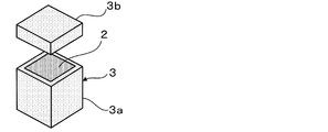
- it is a perspective view which shows the porous container before being filled with ceramic powder and sealing by a cover part.
- it is an exploded perspective view showing porous containers of rectangular solid shape (a) and cylindrical shape (b).
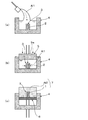
- it is a simple sectional view showing a process from pouring a molten metal to a knockout process in order of processes.
- it is a perspective view which shows the process after a knockout process in order of a process.
- the method for producing an aluminum alloy matrix composite material of the present embodiment is, as shown in FIGS. 1 to 3, a method for producing an aluminum alloy matrix composite material 1 in which a ceramic powder 2 as a reinforcing material is compounded in an aluminum alloy. And filling the ceramic container 2 with the porous container 3 made of a porous material, and placing the porous container 3 in the mold 4 and pouring the molten metal Al1 of the aluminum alloy into the mold 4 It has a process and an impregnating process of applying pressure to the molten metal Al1 in the mold 4 and impregnating the ceramic powder 2 inside with the molten metal Al1 through the porous container 3. Moreover, the manufacturing method of this embodiment has the preheating process which preheats the porous container 3 after the said filling process.
- the porous container 3 is formed of a porous (open porous) material having innumerable communication holes which do not melt even if the aluminum alloy molten metal Al1 is put therein.
- the porous container 3 is preferably made of carbon graphite.
- a powder of aluminum borate (9Al 2 O 3 .2B 2 O 3 ) is used as the ceramic powder 2.
- a powder of SiC silicon carbide is further added as the ceramic powder 2. In that case, in the filling step, it is preferable to mix the powder of aluminum borate with the powder of 20 at a volume ratio of 0.5 to 2.0.
- the case where the mixed powder of aluminum borate and SiC is used as the ceramic powder 2 using the porous container 3 of carbon graphite is demonstrated in more detail.
- a predetermined ceramic powder 2 is prepared and, as shown in FIG. 1, filled in a porous container 3 of carbon graphite.
- each other is sufficiently stirred and mixed uniformly by a rotary mixer etc.
- alloy numbers A1050, A5052, A6061, A7075, AC4C, AC8A, ADC12 and the like can be adopted, and other types can also be adopted.
- AC4C, AC8A and the like having high thermal conductivity and high strength are preferable for the aluminum alloy as materials having good physical properties and less occurrence of impregnation defects.
- the chemical composition of such an alloy is a volume ratio of Si: 6 to 13%, Mg: 0.2 to 1.3%, and Al: the remaining aluminum alloy.
- the content of Si described above is low, impregnation defects are likely to occur at the time of high pressure impregnation, so the content of Si is preferably set in the range of 6 to 12% by volume. That is, when the volume fraction of Si is less than 6%, the flow of the molten metal becomes worse, and it becomes difficult for the molten metal of the aluminum alloy to penetrate into the ceramic powder 2 as the reinforcing material.
- a powder of aluminum borate used for the ceramic powder 2 for example, one having a center particle diameter of about 30 to 50 ⁇ m is adopted, and as a SiC powder, for example, one having a center particle diameter of 2 to 4 ⁇ m is adopted Be done.
- porous container 3 those of various shapes using an open porous carbon graphite block can be adopted.
- a rectangular parallelepiped container 3 comprising a box-shaped main body 3a and a lid 3b may be used, or as shown in FIG. 2 (b), a bottomed cylindrical shape A container 23 may be employed, which comprises the main body 23a and the lid 23b.
- the porous diameter of the porous container 3 is preferably 10 ⁇ m or less.
- the SiC powder whose particle diameter is smaller than the diameter of the porous body does not flow out through the porous flow path.
- the porous container 3 can be filled in a state in which a gap is unlikely to be generated by filling the porous container 3 while applying vibration to the porous container 3.
- the porous container 3 is placed in a preheating furnace (muffle furnace etc.) together with the lid 3b in a sealed state, and preheated at, for example, 500 to 700.degree.
- This preheating step is a step for enhancing the interfacial energy of the ceramic powder 2 and improving the wettability with the aluminum alloy melt.
- the coefficient of thermal expansion coefficient is 14 to 17 ppm / k, so there is a problem that expansion deformation of the container occurs at the time of preheating.
- the more complicated the container shape the more difficult the design considering thermal expansion becomes.
- the porous container 3 using the carbon-graphite block of the present embodiment has an average coefficient of thermal expansion coefficient of about 5 to 7 ppm / k, so deformation of the container due to thermal expansion at the time of preheating hardly occurs. There is an advantage.
- the porous container 3 filled with the preheated ceramic powder 2 is placed in a mold 4 preheated to 200 to 250 ° C. Is poured into the mold 4.
- a plurality of projections may be provided on the bottom of the mold 4 so that the molten metal Al1 flows below the bottom of the porous container 3, and the porous container 3 may be placed on the plurality of projections.
- the porous container 3 can be installed in a floating state from the bottom of the mold 4, and the molten metal Al 1 can be wound around the bottom of the porous container 3.
- the molten metal Al1 can be permeated into the interior from all directions of the porous container 3.
- the aluminum alloy melt Al1 is quantitatively poured into the mold 4, as shown in FIG. 3B, the aluminum alloy melt Al1 is pressurized at 80 to 140 MPa by the punch 5a of the press 5. At this time, the porous container 3 is impregnated with the molten metal Al 1 of the aluminum alloy by pressure energy, and is further impregnated with the ceramic powder 2 in the porous container 3.
- Pressurization is continued in the press 5 until the aluminum alloy melt Al1 is completely solidified.
- the impregnation speed (flow velocity) of the molten alloy Al1 of this aluminum alloy is high, a turbulent flow occurs to move the ceramic powder 2, and the distribution of the ceramic powder 2 becomes uneven, and the insertion of aluminum called metal vane is
- the impregnation speed is set to a low speed so that turbulence does not occur. Therefore, the pressing force and the pressing speed by the press 5 are adjusted by the volume ratio and the shape of the ceramic powder 2 in the porous container 3.
- the porous container 3 and the aluminum inside thereof are knocked out by the knockout 6 in the mold 4.
- An integrally formed product 7 composed of the alloy base composite material 1 and the hardened portion Al 2 of the hardened aluminum alloy is taken out from the mold 4. Furthermore, as shown in (a) of FIG. 4, the single-piece 7 taken out is cut with a band saw or the like along the cutting line C, for example, and the excess thickness Al2 is removed, as shown in FIG. As shown to (b) of, the porous container 3 is exposed.
- the lid 3 b of the porous container 3 is removed, and as shown in (d) of FIG. 4, the wall portion and the bottom portion of the porous container 3 are cut.
- the composite material 1 is taken out by removing it.
- the porous container 3 is carbon graphite, the composite material 1 can be easily taken out.
- the composite material 1 taken out is processed into a desired shape by milling, polishing, NC processing or the like.
- the aluminum alloy base composite material 1 produced in the present embodiment illustrated uses the aluminum alloy as a base material, and contains 30 to 40% of aluminum borate and 1.5 to 2% of SiC by volume ratio as a reinforcing material. It is a composite material in which a ceramic powder 2 composed of an aluminum borate powder and a SiC powder is uniformly dispersed in an aluminum alloy matrix.
- the porous material of the porous container 3 is used.
- the molten aluminum Al 1 of the aluminum alloy uniformly flows into the porous container 3 from almost all directions, and uniform impregnation can be performed on the entire ceramic powder 2.
- the porous container 3 is formed of carbon graphite, the thermal expansion coefficient is smaller than that of iron or SUS containers, and deformation of the container due to thermal expansion hardly occurs, so that a container having a complicated shape is used. Will also be possible.
- the porous container 3 is carbon graphite, it is possible to separate the composite material 1 and the porous container 3 easily.
- the preheating step of preheating the porous container 3 is included after the filling step, the interface energy of the particles of the filled ceramic powder 2 becomes high, and the wettability with the aluminum alloy molten metal Al 1 is improved.
- the porous container 3 is formed of carbon graphite, the thermal expansion coefficient of the porous container 3 is low, and deformation of the container due to preheating hardly occurs.
- the ceramic powder 2 is a powder of aluminum borate
- a powder of aluminum borate having a relatively low hardness it is possible to obtain a composite material excellent in processability.
- powder of SiC is further added as ceramic powder 2
- the total coefficient of thermal expansion is lowered according to the addition ratio of SiC powder having a lower coefficient of thermal expansion than aluminum borate used in combination and high hardness. , Can increase the hardness.
- the wettability with the powder of aluminum borate is good, the interface with the powder of aluminum borate is modified, and a stronger bond can be obtained.
- the powder of aluminum borate is mixed with the powder of 20 at a ratio by volume to the powder of SiC at a ratio of 0.5 to 2.0, thereby reducing the overall thermal expansion coefficient and processing well. It is possible to obtain a composite material compatible with the properties.
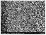
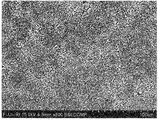
- FIGS. 7 to 10 SEM images of the aluminum alloy based composite materials actually produced based on the manufacturing method of the embodiment described above are shown in FIGS. 7 to 10.
- 7 and 8 are SEM images of an aluminum alloy matrix composite material using only aluminum borate as a ceramic powder.
- 9 and 10 are SEM images of an aluminum alloy based composite material using a mixed powder of aluminum borate and SiC as a ceramic powder. In both cases, an aluminum alloy of alloy number AC4C was used.
- FIG.5 and FIG.6 the SEM image was shown in FIG.5 and FIG.6 about the aluminum alloy base composite material produced based on the conventional manufacturing method shown in FIG.
- This conventional example is an aluminum alloy based composite material using only aluminum borate as a ceramic powder.
- the aluminum borate powder and the surrounding aluminum are distinguished by clear shading, and the boundary of the structure is clear, whereas in the present embodiment
- the shading of the aluminum borate powder and the surrounding aluminum is not clear as compared with the conventional example, and the boundary of the structure is not clear.
- the tendency is more remarkable in the material of the example of the present invention in which the powder of SiC is mixed.
- the material of the embodiment of the present invention has a stronger bond between aluminum borate and aluminum and the boundary between them is unclear compared to the material of the conventional example, and in particular, the SiC powder It is considered that the wettability was further improved and the bonding was further strengthened in the material of the example in which Moreover, it turns out that ceramic powder is disperse
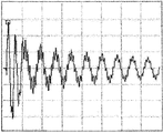
- vibration damping characteristics For vibration damping characteristics, a test piece (10 ⁇ 10 ⁇ 100 mm) of the composite material suspended by a string was vibrated by an impulse hammer, and the resulting vibration was detected by an accelerometer and measured by an FFT analyzer. And based on what plotted the peak of the damping wave of each composite material, damping ratio was computed and evaluated from a multiplier coefficient and frequency. Then, the vibration damping characteristics of the aluminum alloy matrix composite produced in the example of the present invention are shown in FIG. Further, for comparison, the vibration damping characteristics of aluminum are shown in FIG. 11, and the vibration damping characteristics of the aluminum alloy matrix composite material manufactured by the method of the conventional example shown in FIG. 14 are shown in FIG.
- the machinability was evaluated by observing the rake surface and the front flank of the tool when the composite material was subjected to three-dimensional cutting under a predetermined condition by an NC lathe using a metallurgical microscope and measuring the flank friction width.
- the aluminum alloy base composite material of the example of the present invention is significantly higher in Young's modulus, about 40% in density, and about 2.5 times in thermal conductivity than cast iron. It confirmed that it had a characteristic.
- the aluminum alloy matrix composite material of the example of the present invention has good processability comparable to that of 2000 series aluminum as compared with alumina ceramics.
- the aluminum alloy (T6 process) of alloy number A6061 although the tensile strength in 300 degreeC is about 30 Mpa, the aluminum alloy base composite material of the Example of this invention had high tensile strength of 90 Mpa.
- the thermal conductivity of an aluminum alloy based composite material (aluminum alloy based aluminum borate reinforced composite material) according to the conventional manufacturing method using only aluminum borate having a low thermal expansion coefficient of 8 to 10 w / m ⁇ k as a ceramic powder was low and the heat dissipation was poor.
- the thermal conductivity and the mechanical characteristics were improved as compared with the material of the conventional example.
- the aluminum alloy base composite material of the Example of this invention did not substantially change a processing characteristic, and was favorable.
- the vibration damping characteristics of the aluminum alloy matrix composite material obtained by the manufacturing method of the present embodiment are improved as compared with the aluminum alloy matrix aluminum borate reinforced composite material obtained by the conventional manufacturing method.
- the conventional aluminum alloy-based silicon carbide reinforced composite material is excellent in vibration damping characteristics but inferior in processability, whereas the aluminum alloy-based composite material of the embodiment of the present invention is also excellent in processability.
- the vibration damping characteristics of the aluminum shown in FIG. 11 are such that the vibration is not easily damped, but in the aluminum alloy based composite material of the embodiment of the present invention shown in FIG. Is obtained.
- the aluminum alloy matrix composite material of the conventional example shown in FIG. 12 has a lot of noise in the attenuation waveform
- the noise component of the aluminum alloy matrix composite material of the embodiment of the present invention shown in FIG. It was confirmed that there were few. This is because in the conventional aluminum alloy matrix composite material, there is a portion with insufficient bonding in the structure, and the bonding strength is nonuniform as a whole, resulting in noise in the attenuation waveform, which is an embodiment of the present invention.
- the aluminum alloy matrix composite material it is considered that a damping waveform with less noise component is obtained because the bonding in the tissue is uniform and strong.
- An aluminum alloy matrix composite produced by the process of the present invention is preferable as a material to be used.
Landscapes
- Engineering & Computer Science (AREA)
- Mechanical Engineering (AREA)
- Chemical & Material Sciences (AREA)
- Materials Engineering (AREA)
- Metallurgy (AREA)
- Organic Chemistry (AREA)
- Manufacture Of Alloys Or Alloy Compounds (AREA)
Abstract
均一にアルミニウム合金を含浸させることができるアルミニウム合金基複合材料の製造方法を提供する。アルミニウム合金の中に強化材であるセラミックス粉末が複合されたアルミニウム合金基複合材料の製造方法であって、前記セラミックス粉末を多孔質材料で形成された多孔質容器に充填し、前記多孔質容器を蓋部により密閉する充填工程と、前記多孔質容器を金型内に設置し、前記金型内にアルミニウム合金の溶湯を流し込む工程と、前記金型内の前記溶湯に圧力を加え、前記多孔質容器を通して内部の前記セラミックス粉末に前記溶湯を含浸させる含浸工程とを有していることを特徴とするアルミニウム合金基複合材料の製造方法及びアルミニウム合金基複合材料である。
Description
本発明は、強化材が均一に分布したアルミニウム合金基複合材料の製造方法及びアルミニウム合金基複合材料に関する。
従来、アルミニウム合金の中に強化材であるセラミックス粉末が複合されたアルミニウム合金基複合材料が知られている。このアルミニウム合金基複合材料の製造方法としては、例えば特許文献1には、強化材であるセラミックス粉末としてホウ酸アルミニウムの粉末を用いて、この粉末の充填体にアルミニウム合金の溶湯を含浸させるアルミニウム合金基複合材料の製造方法が記載されている。なお、このような製造方法は、溶湯鋳造法又は高圧鋳造法といわれる。
上記特許文献1に記載の製造方法は、ホウ酸アルミニウム粉末原料を充填して充填体を得る工程と、充填体を予熱する工程と、アルミニウム合金を加熱して溶融アルミニウム合金を得る工程と、予熱した充填体に溶融アルミニウム合金を加圧浸透させる工程とを含んでいる。このような従来の製法では、鉄製やSUS製の容器にホウ酸アルミニウム粉末原料等のセラミックス粉末を充填することで充填体を得ている。
上記従来の技術には、以下の課題が残されている。
すなわち、従来のアルミニウム合金基複合材料の製造方法では、図14に示すように、鉄製やSUS製の金属容器103にセラミックス粉末102を充填して充填体とし、この金属容器103の上部開口からアルミニウム合金の溶湯Al1を流入させてセラミックス粉末102の充填体にアルミニウム合金を含浸させるため、アルミニウム合金の溶湯Al1が流入する開口部付近と、開口部から遠い底部分とでは、アルミニウム合金の含浸率が異なり、セラミックス粉末102の充填体全体に均一に含浸されないという問題があった。そのため、特に複雑な形状や薄板状において、均一な複合材料を得ることが困難であった。
すなわち、従来のアルミニウム合金基複合材料の製造方法では、図14に示すように、鉄製やSUS製の金属容器103にセラミックス粉末102を充填して充填体とし、この金属容器103の上部開口からアルミニウム合金の溶湯Al1を流入させてセラミックス粉末102の充填体にアルミニウム合金を含浸させるため、アルミニウム合金の溶湯Al1が流入する開口部付近と、開口部から遠い底部分とでは、アルミニウム合金の含浸率が異なり、セラミックス粉末102の充填体全体に均一に含浸されないという問題があった。そのため、特に複雑な形状や薄板状において、均一な複合材料を得ることが困難であった。
本発明は、前述の課題に鑑みてなされたもので、均一にアルミニウム合金を含浸させることができるアルミニウム合金基複合材料の製造技術を提供することを目的とする。
本発明は、前記課題を解決するために以下の構成を採用した。すなわち、第1の発明に係るアルミニウム合金基複合材料の製造方法は、アルミニウム合金の中に強化材であるセラミックス粉末が複合されたアルミニウム合金基複合材料の製造方法であって、前記セラミックス粉末を多孔質材料で形成された多孔質容器に充填し、前記多孔質容器を蓋部により密閉する充填工程と、前記多孔質容器を金型内に設置し、前記金型内にアルミニウム合金の溶湯を流し込む工程と、前記金型内の前記溶湯に圧力を加え、前記多孔質容器を通して内部の前記セラミックス粉末に前記溶湯を含浸させる含浸工程とを有していることを特徴とする。
このアルミニウム合金基複合材料の製造方法では、多孔質容器を通して内部のセラミックス粉末に溶湯を含浸させる含浸工程を有しているので、多孔質容器のポーラスな材質を介してほぼ全方位からアルミニウム合金の溶湯が均等に多孔質容器内に流入し、セラミックス粉末全体に対して均一な含浸が可能になる。
第2の発明に係るアルミニウム合金基複合材料の製造方法は、第1の発明において、前記多孔質容器が、カーボングラファイトで形成されていることを特徴とする。
すなわち、このアルミニウム合金基複合材料の製造方法では、多孔質容器が、カーボングラファイトで形成されているので、熱膨張率が鉄製やSUS製の容器よりも小さく、熱膨張による容器の変形がほとんど生じず、複雑な形状の容器を用いることも可能になる。また、含浸工程後に硬化した複合材料を多孔質容器から取り出す際に、多孔質容器がカーボングラファイトであるため、容易に複合材料と多孔質容器とを分離することが可能である。
すなわち、このアルミニウム合金基複合材料の製造方法では、多孔質容器が、カーボングラファイトで形成されているので、熱膨張率が鉄製やSUS製の容器よりも小さく、熱膨張による容器の変形がほとんど生じず、複雑な形状の容器を用いることも可能になる。また、含浸工程後に硬化した複合材料を多孔質容器から取り出す際に、多孔質容器がカーボングラファイトであるため、容易に複合材料と多孔質容器とを分離することが可能である。
第3の発明に係るアルミニウム合金基複合材料の製造方法は、第1又は第2の発明において、前記充填工程後に、前記多孔質容器を予熱する予熱工程を有していることを特徴とする。
すなわち、このアルミニウム合金基複合材料の製造方法では、充填工程後に、多孔質容器を予熱する予熱工程を有しているので、充填されたセラミックス粉末の粒子の界面エネルギーが高くなり、アルミニウム合金の溶湯との濡れ性が改善する。特に、多孔質容器がカーボングラファイトで形成されていることで、多孔質容器の熱膨張率が低く、予熱による容器の変形がほとんど発生しない。
すなわち、このアルミニウム合金基複合材料の製造方法では、充填工程後に、多孔質容器を予熱する予熱工程を有しているので、充填されたセラミックス粉末の粒子の界面エネルギーが高くなり、アルミニウム合金の溶湯との濡れ性が改善する。特に、多孔質容器がカーボングラファイトで形成されていることで、多孔質容器の熱膨張率が低く、予熱による容器の変形がほとんど発生しない。
第4の発明に係るアルミニウム合金基複合材料の製造方法は、第1から第3の発明のいずれかにおいて、前記セラミックス粉末が、ホウ酸アルミニウムの粉末であることを特徴とする。
すなわち、このアルミニウム合金基複合材料の製造方法では、セラミックス粉末が、ホウ酸アルミニウムの粉末であるので、比較的硬度の低いホウ酸アルミニウムの粉末を用いることで、加工性に優れた複合材料を得ることができる。
すなわち、このアルミニウム合金基複合材料の製造方法では、セラミックス粉末が、ホウ酸アルミニウムの粉末であるので、比較的硬度の低いホウ酸アルミニウムの粉末を用いることで、加工性に優れた複合材料を得ることができる。
第5の発明に係るアルミニウム合金基複合材料の製造方法は、第4の発明において、前記セラミックス粉末として、さらにSiCの粉末が添加されていることを特徴とする。
すなわち、このアルミニウム合金基複合材料の製造方法では、セラミックス粉末として、さらにSiCの粉末が添加されているので、ホウ酸アルミニウムよりも熱膨張率が低く硬度の高いSiCの粉末の添加割合に応じて全体の熱膨張率を下げると共に硬度を高めることができる。
また、SiCの粉末の効果として、ホウ酸アルミニウムの粉末との濡れ性が良く、ホウ酸アルミニウム粉末との界面が改質され、より強固な接合を得ることができる。
すなわち、このアルミニウム合金基複合材料の製造方法では、セラミックス粉末として、さらにSiCの粉末が添加されているので、ホウ酸アルミニウムよりも熱膨張率が低く硬度の高いSiCの粉末の添加割合に応じて全体の熱膨張率を下げると共に硬度を高めることができる。
また、SiCの粉末の効果として、ホウ酸アルミニウムの粉末との濡れ性が良く、ホウ酸アルミニウム粉末との界面が改質され、より強固な接合を得ることができる。
第6の発明に係るアルミニウム合金基複合材料の製造方法は、第5の発明において、前記充填工程において、体積割合で前記ホウ酸アルミニウムの粉末が20に対して、前記SiCの粉末を0.5~2.0の割合で混合することを特徴とする。
すなわち、このアルミニウム合金基複合材料の製造方法では、充填工程において、体積割合でホウ酸アルミニウムの粉末が20に対して、SiCの粉末を0.5~2.0の割合で混合するので、全体の熱膨張率の低下と良好な加工性とを両立した複合材料を得ることができる。
なお、体積割合でホウ酸アルミニウムの粉末が20に対して、SiCの粉末の割合が0.5未満であると、熱膨張率の低下効果が十分に得られないと共に、SiCの粉末の割合が1.5を超えると、全体の硬度が高くなり過ぎ、加工性が悪くなってしまう。
すなわち、このアルミニウム合金基複合材料の製造方法では、充填工程において、体積割合でホウ酸アルミニウムの粉末が20に対して、SiCの粉末を0.5~2.0の割合で混合するので、全体の熱膨張率の低下と良好な加工性とを両立した複合材料を得ることができる。
なお、体積割合でホウ酸アルミニウムの粉末が20に対して、SiCの粉末の割合が0.5未満であると、熱膨張率の低下効果が十分に得られないと共に、SiCの粉末の割合が1.5を超えると、全体の硬度が高くなり過ぎ、加工性が悪くなってしまう。
第7の発明に係るアルミニウム合金基複合材料は、アルミニウム合金マトリックス中に強化材であるセラミックス粉末が均一に分散、分布してなるアルミニウム合金の中に強化材であるセラミックス粉末が複合されたアルミニウム合金基複合材料であって、第1から第6の発明のいずれかに記載のアルミニウム合金基複合材料の製造方法で得られたことを特徴とするアルミニウム合金基複合材料である。
本発明によれば、以下の効果を奏する。
すなわち、本発明に係るアルミニウム合金基複合材料の製造方法によれば、多孔質容器を通して内部のセラミックス粉末に溶湯を含浸させる含浸工程を有しているので、多孔質容器のポーラスな材質を介してほぼ全方位からアルミニウム合金の溶湯が均等に多孔質容器内に流入し、セラミックス粉末全体に対して均一な含浸が可能になる。
したがって、本発明の製造方法では、全体として均一な熱膨張率や硬度を有したアルミニウム合金基複合材料を得ることが可能であると共に複雑な形状や薄板状の均一なアルミニウム合金基複合材料を得ることが可能になる。
すなわち、本発明に係るアルミニウム合金基複合材料の製造方法によれば、多孔質容器を通して内部のセラミックス粉末に溶湯を含浸させる含浸工程を有しているので、多孔質容器のポーラスな材質を介してほぼ全方位からアルミニウム合金の溶湯が均等に多孔質容器内に流入し、セラミックス粉末全体に対して均一な含浸が可能になる。
したがって、本発明の製造方法では、全体として均一な熱膨張率や硬度を有したアルミニウム合金基複合材料を得ることが可能であると共に複雑な形状や薄板状の均一なアルミニウム合金基複合材料を得ることが可能になる。
この本発明の製法で作製したアルミニウム合金基複合材料は、軽量で、高ヤング率、高振動減衰率、高熱伝導性及び高耐摩耗性を有することから、ボンディングマシンなどのX-Yテーブル、半導体製造装置などに使用されるロボットアーム、チップマウンタ-、空気圧縮機用スクロール部品などの材料として好適である。
以下、本発明に係るアルミニウム合金基複合材料の製造方法の一実施形態を、図1から図6を参照しながら説明する。
本実施形態のアルミニウム合金基複合材料の製造方法は、図1から図3に示すように、アルミニウム合金の中に強化材であるセラミックス粉末2が複合されたアルミニウム合金基複合材料1の製造方法であって、セラミックス粉末2を多孔質材料で形成された多孔質容器3に充填する充填工程と、多孔質容器3を金型4内に設置し、金型4内にアルミニウム合金の溶湯Al1を流し込む工程と、金型4内の溶湯Al1に圧力を加え、多孔質容器3を通して内部のセラミックス粉末2に溶湯Al1を含浸させる含浸工程とを有している。
また、本実施形態の製造方法は、上記充填工程後に、多孔質容器3を予熱する予熱工程を有している。
また、本実施形態の製造方法は、上記充填工程後に、多孔質容器3を予熱する予熱工程を有している。
上記多孔質容器3は、アルミニウム合金の溶湯Al1を入れても溶けない無数の連通孔を有する多孔質(オープンポーラス)な材料で形成されている。特に、多孔質容器3をカーボングラファイトで形成することが好ましい。
上記セラミックス粉末2は、例えばホウ酸アルミニウム(9Al2O3・2B2O3)の粉末が用いられる。
また、ホウ酸アルミニウムよりも熱膨張率が低く硬度の高い複合材を得るためには、セラミックス粉末2として、さらにSiC(炭化ケイ素)の粉末が添加される。
その場合、充填工程において、体積割合でホウ酸アルミニウムの粉末が20に対して、SiCの粉末を0.5~2.0の割合で混合することが好ましい。
上記セラミックス粉末2は、例えばホウ酸アルミニウム(9Al2O3・2B2O3)の粉末が用いられる。
また、ホウ酸アルミニウムよりも熱膨張率が低く硬度の高い複合材を得るためには、セラミックス粉末2として、さらにSiC(炭化ケイ素)の粉末が添加される。
その場合、充填工程において、体積割合でホウ酸アルミニウムの粉末が20に対して、SiCの粉末を0.5~2.0の割合で混合することが好ましい。
本実施形態の製造方法について、カーボングラファイトの多孔質容器3を用い、セラミックス粉末2として、ホウ酸アルミニウムとSiCとの混合粉末を用いた場合について、より詳細に説明する。まず、所定のセラミックス粉末2を用意し、図1に示すように、カーボングラファイトの多孔質容器3内に充填する。なお、ホウ酸アルミニウムとSiCとの混合粉末をセラミックス粉末2とする場合は、予め、所定の割合で両粉末を混合すると共に、回転混合機等によって十分に互いを均一に撹拌混合させる。
本実施形態の製造方法に利用できるアルミニウム合金としては、例えば、合金番号A1050,A5052,A6061,A7075,AC4C,AC8A,ADC12等が採用可能であり、他の種類も採用可能である。特に、物性が良く、含浸不良が発生し難いものとして、高熱伝導率かつ高強度なAC4C,AC8A等がアルミニウム合金に好ましい。このような合金の化学組成は、体積率がSi:6~13%、Mg:0.2~1.3%、Al:残のアルミニウム合金である。
なお、上記したSiの含有率が少ないと高圧含浸時に含浸不良が発生し易いため、含有するSiは体積率6~12%の範囲に設定することが好ましい。すなわち、Siの体積率が6%未満であると、湯流れが悪くなり、強化材であるセラミックス粉末2間にアルミニウム合金の溶湯が浸透し難くなるためである。
また、セラミックス粉末2に利用されるホウ酸アルミニウムの粉末としては、例えば、中心粒径30~50μm程度のものが採用され、SiCの粉末としては、例えば、中心粒径2~4μmのものが採用される。
また、セラミックス粉末2に利用されるホウ酸アルミニウムの粉末としては、例えば、中心粒径30~50μm程度のものが採用され、SiCの粉末としては、例えば、中心粒径2~4μmのものが採用される。
上記多孔質容器3としては、オープンポーラスなカーボングラファイトブロックを用いた種々の形状のものが採用可能である。例えば、図2の(a)に示すように、箱形の本体3aと蓋部3bとからなる直方体形状の容器3としても良いし、図2の(b)に示すように、有底円筒形状の本体23aと蓋部23bとからなる容器23を採用しても構わない。
多孔質容器3のポーラス径としては、10μm以下が望ましい。なお、多孔質容器3のポーラスの流路は複雑であるため、ポーラス径よりも粒径が小さいSiC粉末がポーラスの流路をつたって外部に流出することはない。
多孔質容器3のポーラス径としては、10μm以下が望ましい。なお、多孔質容器3のポーラスの流路は複雑であるため、ポーラス径よりも粒径が小さいSiC粉末がポーラスの流路をつたって外部に流出することはない。
セラミックス粉末2を多孔質容器3内に充填する場合、振動機等によって多孔質容器3に振動を加えながら詰めることで、隙間が生じ難い状態で充填することができる。
充填後に、蓋部3bにより密閉した状態で多孔質容器3ごと予熱炉(マッフル炉等)に入れて、例えば500~700℃で予熱する。この予熱工程は、セラミックス粉末2の界面エネルギーを高め、アルミニウム合金の溶湯との濡れ性を改善するための工程である。
充填後に、蓋部3bにより密閉した状態で多孔質容器3ごと予熱炉(マッフル炉等)に入れて、例えば500~700℃で予熱する。この予熱工程は、セラミックス粉末2の界面エネルギーを高め、アルミニウム合金の溶湯との濡れ性を改善するための工程である。
ここで、従来の鉄製やSUS製の容器では、平均熱膨張率係数が14~17ppm/kであるため、予熱時に容器の膨張変形が発生してしまうという課題があった。特に、容器形状が複雑になるほど、熱膨張を考慮した設計が困難になる。これに対し、本実施形態のカーボングラファイトブロックを用いた多孔質容器3は、平均熱膨張率係数が5~7ppm/k程度であるので、予熱時の熱膨張による容器の変形がほとんど発生しないという利点がある。
次に、図3の(a)に示すように、予熱したセラミックス粉末2を詰めた多孔質容器3を、予め200~250℃に予熱した金型4内に設置して、アルミニウム合金の溶湯Al1を金型4内に流し込む。
この際、多孔質容器3の底部下まで溶湯Al1が流れるように、金型4の底部に複数の凸部を設け、複数の凸部上に多孔質容器3を載置しても構わない。この場合、金型4の底部から多孔質容器3を浮かした状態で設置でき、多孔質容器3の底部下まで溶湯Al1を回り込ませることが可能になる。これにより、多孔質容器3の全方位から溶湯Al1を内部に浸透させることができるようになる。
この際、多孔質容器3の底部下まで溶湯Al1が流れるように、金型4の底部に複数の凸部を設け、複数の凸部上に多孔質容器3を載置しても構わない。この場合、金型4の底部から多孔質容器3を浮かした状態で設置でき、多孔質容器3の底部下まで溶湯Al1を回り込ませることが可能になる。これにより、多孔質容器3の全方位から溶湯Al1を内部に浸透させることができるようになる。
アルミニウム合金の溶湯Al1を金型4内に定量流し込んだ後、図3の(b)に示すように、プレス機5のパンチ5aによりアルミニウム合金の溶湯Al1を80~140MPaで加圧する。
この際、加圧エネルギーにより、アルミニウム合金の溶湯Al1が多孔質容器3に含浸され、さらに多孔質容器3内のセラミックス粉末2に含浸される。
この際、加圧エネルギーにより、アルミニウム合金の溶湯Al1が多孔質容器3に含浸され、さらに多孔質容器3内のセラミックス粉末2に含浸される。
このアルミニウム合金の溶湯Al1が完全に凝固するまで、プレス機5にて加圧を続ける。
このアルミニウム合金の溶湯Al1の含浸スピード(流速)が速いと、乱流が発生し、セラミックス粉末2を移動させてしまい、セラミックス粉末2の分布が偏ってしまうと共に、メタルベインと呼ばれるアルミニウムの差し込みが発生してしまうため、乱流が発生しないように含浸スピードは低速に設定される。したがって、プレス機5による加圧力と加圧スピードとは、多孔質容器3内のセラミックス粉末2の体積率や形状によって調整される。
このアルミニウム合金の溶湯Al1の含浸スピード(流速)が速いと、乱流が発生し、セラミックス粉末2を移動させてしまい、セラミックス粉末2の分布が偏ってしまうと共に、メタルベインと呼ばれるアルミニウムの差し込みが発生してしまうため、乱流が発生しないように含浸スピードは低速に設定される。したがって、プレス機5による加圧力と加圧スピードとは、多孔質容器3内のセラミックス粉末2の体積率や形状によって調整される。
次に、上記含浸が終了し、温度が200~300℃程度まで低下したところで、図3の(c)に示すように、金型4内のノックアウト6によって、多孔質容器3とその内部のアルミニウム合金基複合材料1と硬化したアルミニウム合金の余肉部Al2とからなる一体成形物7を金型4から取り出す。
さらに、図4の(a)に示すように、取り出した一体成形物7をバンドソー等により、例えば切断線Cに沿って一体成形物7を切断し、余肉部Al2を取り除くことで、図4の(b)に示すように、多孔質容器3を露出させる。
さらに、図4の(a)に示すように、取り出した一体成形物7をバンドソー等により、例えば切断線Cに沿って一体成形物7を切断し、余肉部Al2を取り除くことで、図4の(b)に示すように、多孔質容器3を露出させる。
次に、図4の(c)に示すように、多孔質容器3の蓋部3bを外し、さらに図4の(d)に示すように、多孔質容器3の壁部分及び底部分を切断して外すことで、複合材料1を取り出す。例示した本実施形態では、多孔質容器3がカーボングラファイトであるため、複合材料1を容易に取り出すことができる。
取り出した複合材料1は、フライスや研磨、NC加工等によって、目的の形状に加工される。例示した本実施形態で作製されたアルミニウム合金基複合材料1は、アルミニウム合金を母材とし、強化材として体積率でホウ酸アルミニウムが30~40%、SiCが1.5~2%を含んだものであり、アルミニウム合金マトリックス中にホウ酸アルミニウムの粉末とSiCの粉末とからなるセラミックス粉末2が均一に分散した複合材料である。
本実施形態のアルミニウム合金基複合材料1の製造方法では、多孔質容器3を通して内部のセラミックス粉末2に溶湯Al1を含浸させる含浸工程を有しているので、多孔質容器3のポーラスな材質を介してほぼ全方位からアルミニウム合金の溶湯Al1が均等に多孔質容器3内に流入し、セラミックス粉末2全体に対して均一な含浸が可能になる。
また、多孔質容器3が、カーボングラファイトで形成されているので、熱膨張率が鉄製やSUS製の容器よりも小さく、熱膨張による容器の変形がほとんど生じず、複雑な形状の容器を用いることも可能になる。また、含浸工程後に硬化した複合材料1を多孔質容器3から取り出す際に、多孔質容器3がカーボングラファイトであるため、容易に複合材料1と多孔質容器3とを分離することが可能である。
また、充填工程後に、多孔質容器3を予熱する予熱工程を有しているので、充填されたセラミックス粉末2の粒子の界面エネルギーが高くなり、アルミニウム合金の溶湯Al1との濡れ性が改善する。特に、多孔質容器3がカーボングラファイトで形成されていることで、多孔質容器3の熱膨張率が低く、予熱による容器の変形がほとんど発生しない。
また、セラミックス粉末2が、ホウ酸アルミニウムの粉末である場合に、比較的硬度の低いホウ酸アルミニウムの粉末を用いることで、加工性に優れた複合材料を得ることが可能になる。
また、セラミックス粉末2として、さらにSiCの粉末が添加される場合は、併用するホウ酸アルミニウムよりも熱膨張率が低く硬度の高いSiCの粉末の添加割合に応じて全体の熱膨張率を下げると共に、硬度を高めることができる。
また、SiCの粉末を併用する効果として、ホウ酸アルミニウムの粉末との濡れ性が良く、ホウ酸アルミニウム粉末との界面が改質され、より強固な接合を得ることができる。
特に、充填工程において、体積割合でホウ酸アルミニウムの粉末が20に対して、SiCの粉末を0.5~2.0の割合で混合することで、全体の熱膨張率の低下と良好な加工性とを両立した複合材料を得ることができる。
また、セラミックス粉末2として、さらにSiCの粉末が添加される場合は、併用するホウ酸アルミニウムよりも熱膨張率が低く硬度の高いSiCの粉末の添加割合に応じて全体の熱膨張率を下げると共に、硬度を高めることができる。
また、SiCの粉末を併用する効果として、ホウ酸アルミニウムの粉末との濡れ性が良く、ホウ酸アルミニウム粉末との界面が改質され、より強固な接合を得ることができる。
特に、充填工程において、体積割合でホウ酸アルミニウムの粉末が20に対して、SiCの粉末を0.5~2.0の割合で混合することで、全体の熱膨張率の低下と良好な加工性とを両立した複合材料を得ることができる。
上記で説明した実施形態の製造方法に基づいて実際に作製したアルミニウム合金基複合材料について、SEM画像を図7から図10に示した。
図7及び図8は、セラミックス粉末としてホウ酸アルミニウムのみを用いたアルミニウム合金基複合材料のSEM画像である。また、図9及び図10は、セラミックス粉末としてホウ酸アルミニウムとSiCとの混合粉末を用いたアルミニウム合金基複合材料のSEM画像である。なお、どちらの場合も、合金番号AC4Cのアルミニウム合金を用いた。
図7及び図8は、セラミックス粉末としてホウ酸アルミニウムのみを用いたアルミニウム合金基複合材料のSEM画像である。また、図9及び図10は、セラミックス粉末としてホウ酸アルミニウムとSiCとの混合粉末を用いたアルミニウム合金基複合材料のSEM画像である。なお、どちらの場合も、合金番号AC4Cのアルミニウム合金を用いた。
また、図14で示した従来の製造方法に基づいて作製したアルミニウム合金基複合材料について、SEM画像を図5及び図6に示した。この従来例は、セラミックス粉末としてホウ酸アルミニウムのみを用いたアルミニウム合金基複合材料である。
これらの画像から分かるように、従来例で得た材料では、ホウ酸アルミニウムの粉末とその周囲のアルミニウムとが明確な濃淡で見分けられ、組織の境界がはっきりとしているのに対し、本実施形態の製造方法で作製した実施例の材料では、いずれもホウ酸アルミニウムの粉末とその周囲のアルミニウムとの濃淡が従来例に比べて明確でなく、組織の境界がはっきりとしていない。特に、SiCの粉末を混合した本発明の実施例の材料では、その傾向がより顕著になっていることが分かる。これは、本発明の実施例の材料は、従来例の材料に比べて、ホウ酸アルミニウムとアルミニウムとの結合が強く、互いの境界が曖昧になっているためであると考えられ、特にSiC粉末を混合した実施例の材料では、濡れ性がより向上して、さらに結合が強くなったものと考えられる。
また、本実施形態の製造方法で作製することで、いずれの材料も、アルミニウム合金マトリックス中に均一にセラミックス粉末が分散、分布していることが分かる。
また、本実施形態の製造方法で作製することで、いずれの材料も、アルミニウム合金マトリックス中に均一にセラミックス粉末が分散、分布していることが分かる。
次に、本発明の実施例として、セラミックス粉末としてホウ酸アルミニウムとSiCとの混合粉末を用いて、先に説明した実施形態の製造方法で作製したアルミニウム合金基複合材料について、ヤング率、密度、比ヤング率、熱伝導率、振動減衰特性及び加工性について測定した結果を、表1に示した。なお、表1において、本発明の実施例によるアルミニウム合金基複合材料を、「開発品」として記載した。また、比較として、鋳鉄FC100、アルミナセラミックス、従来の製法によるアルミニウム合金基炭化ケイ素強化複合材料、従来の製法によるアルミニウム合金基ホウ酸アルミニウム強化複合材料についても、「従来品」として同様の特性を表1に併せて記載した。

振動減衰特性については、ひもで吊した複合材料の試験片(10×10×100mm)をインパルスハンマで加振し、その結果生じる振動を加速度計で検出し、FFTアナライザで計測した。そして、各複合材料の減衰波の頂点をプロットしたものに基づいて、乗数係数と周波数とから減衰比を算出し、評価を行った。
そして、本発明の実施例で作製したアルミニウム合金基複合材料の振動減衰特性を図13に示した。また、比較のため、アルミニウムの振動減衰特性を図11に示し、図14に示した従来例の方法で作製したアルミニウム合金基複合材料の振動減衰特性を図12に示した。
そして、本発明の実施例で作製したアルミニウム合金基複合材料の振動減衰特性を図13に示した。また、比較のため、アルミニウムの振動減衰特性を図11に示し、図14に示した従来例の方法で作製したアルミニウム合金基複合材料の振動減衰特性を図12に示した。
加工性については、複合材料をNC旋盤により三次元切削を所定の条件で行った際の工具のすくい面、前逃げ面を金属顕微鏡で観察し、逃げ面摩擦幅を測定することで評価した。
これらの測定結果から、本発明の実施例のアルミニウム合金基複合材料は、鋳鉄と比較して、ヤング率が約2倍、密度は約40%、熱伝導率が2.5倍と大幅に高い特性を有していることを確認した。
また、本発明の実施例のアルミニウム合金基複合材料は、アルミナセラミックスと比較して、2000系アルミと同程度の良好な加工性を有していることが分かった。
また、合金番号A6061のアルミニウム合金(T6処理)では、300℃における引張強度が30MPa程度であるが、本発明の実施例のアルミニウム合金基複合材料は、90MPaの高い引張強度を有していた。
また、本発明の実施例のアルミニウム合金基複合材料は、アルミナセラミックスと比較して、2000系アルミと同程度の良好な加工性を有していることが分かった。
また、合金番号A6061のアルミニウム合金(T6処理)では、300℃における引張強度が30MPa程度であるが、本発明の実施例のアルミニウム合金基複合材料は、90MPaの高い引張強度を有していた。
さらに、熱膨張率が8~10w/m・kと低いホウ酸アルミニウムのみをセラミックス粉末として用いた従来の製法によるアルミニウム合金基複合材料(アルミニウム合金基ホウ酸アルミニウム強化複合材料)では、熱伝導率が低く、放熱性が悪かった。これに対し、SiCをさらに添加した本発明の製法で作製した実施例のアルミニウム合金基複合材料は、上記従来例の材料よりも熱伝導率と機械特性とが向上していた。また、SiCを添加しても本発明の実施例のアルミニウム合金基複合材料は、加工特性がほぼ変わらなく、良好であった。
また、本実施形態の製造方法で得たアルミニウム合金基複合材料は、従来の製法で得たアルミニウム合金基ホウ酸アルミニウム強化複合材料に比べて振動減衰特性が向上していることが分かる。従来のアルミニウム合金基炭化ケイ素強化複合材料では、振動減衰特性が優れているが加工性が悪いのに対し、本発明の実施例のアルミニウム合金基複合材料では、加工性も良い。
図11に示したアルミニウムの振動減衰特性は、振動がなかなか減衰していないのに対し、図13に示した本発明の実施例のアルミニウム合金基複合材料では、減衰が早く、良好な振動減衰特性が得られている。また、図12に示す従来例のアルミニウム合金基複合材料は、減衰波形に多くのノイズが生じているのに対し、図13に示す本発明の実施例のアルミニウム合金基複合材料では、ノイズ成分が少ないことが確認された。
これは、従来例のアルミニウム合金基複合材料では、組織内の結合が不十分な部分があり、結合強度が全体として不均一なため、減衰波形にノイズが生じており、本発明の実施例のアルミニウム合金基複合材料では、組織内の結合が、均一かつ強固であるために、ノイズ成分が少ない減衰波形が得られていると考えられる。
これは、従来例のアルミニウム合金基複合材料では、組織内の結合が不十分な部分があり、結合強度が全体として不均一なため、減衰波形にノイズが生じており、本発明の実施例のアルミニウム合金基複合材料では、組織内の結合が、均一かつ強固であるために、ノイズ成分が少ない減衰波形が得られていると考えられる。
したがって、軽量かつ高ヤング率が要求されるだけでなく、高い振動減衰特性や加工性が要求されるボンディングマシンなどのX-Yテーブルや、半導体製造装置などに使用されているロボットアーム等に使用する材料として、本発明の製法で作製されたアルミニウム合金基複合材料は好適である。
なお、本発明の技術範囲は上記実施形態及び実施例に限定されるものではなく、本発明の趣旨を逸脱しない範囲において種々の変更を加えることが可能である。
例えば、上記で例示した実施形態では、セラミックス粉末としてホウ酸アルミニウムやSiCを用いているが、アルミナ(Al3N4)の粉末、ウイスカ状のTi酸カリウムなど1種以上の他のセラミックス粉末を採用することも可能である。
例えば、上記で例示した実施形態では、セラミックス粉末としてホウ酸アルミニウムやSiCを用いているが、アルミナ(Al3N4)の粉末、ウイスカ状のTi酸カリウムなど1種以上の他のセラミックス粉末を採用することも可能である。
1 アルミニウム合金基複合材料
2,102 セラミックス粉末
3,23 多孔質容器
4 金型
6 ノックアウト
103 金属容器
Al1 アルミニウム合金の溶湯
2,102 セラミックス粉末
3,23 多孔質容器
4 金型
6 ノックアウト
103 金属容器
Al1 アルミニウム合金の溶湯
Claims (7)
- アルミニウム合金の中に強化材であるセラミックス粉末が複合されたアルミニウム合金基複合材料の製造方法であって、
前記セラミックス粉末を多孔質材料で形成された多孔質容器に充填し、前記多孔質容器を蓋部により密閉する充填工程と、
前記多孔質容器を金型内に設置し、前記金型内にアルミニウム合金の溶湯を流し込む工程と、
前記金型内の前記溶湯に圧力を加え、前記多孔質容器を通して内部の前記セラミックス粉末に前記溶湯を含浸させる含浸工程とを有していることを特徴とするアルミニウム合金基複合材料の製造方法。 - 請求項1に記載のアルミニウム合金基複合材料の製造方法において、
前記多孔質容器が、カーボングラファイトで形成されていることを特徴とするアルミニウム合金基複合材料の製造方法。 - 請求項1又は2に記載のアルミニウム合金基複合材料の製造方法において、
前記充填工程後に、前記多孔質容器を予熱する予熱工程を有していることを特徴とするアルミニウム合金基複合材料の製造方法。 - 請求項1から3のいずれか一項に記載のアルミニウム合金基複合材料の製造方法において、
前記セラミックス粉末が、ホウ酸アルミニウムの粉末であることを特徴とするアルミニウム合金基複合材料の製造方法。 - 請求項4に記載のアルミニウム合金基複合材料の製造方法において、
前記セラミックス粉末として、さらにSiCの粉末が添加されていることを特徴とするアルミニウム合金基複合材料の製造方法。 - 請求項5に記載のアルミニウム合金基複合材料の製造方法において、
前記充填工程において、体積割合で前記ホウ酸アルミニウムの粉末が20に対して、前記SiCの粉末を0.5~2.0の割合で混合することを特徴とするアルミニウム合金基複合材料の製造方法。 - アルミニウム合金マトリックス中に強化材であるセラミックス粉末が均一に分散、分布してなるアルミニウム合金の中に強化材であるセラミックス粉末が複合されたアルミニウム合金基複合材料であって、
請求項1から6のいずれか一項に記載のアルミニウム合金基複合材料の製造方法で得られたことを特徴とするアルミニウム合金基複合材料。
Priority Applications (2)
| Application Number | Priority Date | Filing Date | Title |
|---|---|---|---|
| CN201880077344.9A CN111479940B (zh) | 2017-11-30 | 2018-11-30 | 铝合金基复合材料的制造方法及铝合金基复合材料 |
| EP18884716.4A EP3719151B1 (en) | 2017-11-30 | 2018-11-30 | Production method for aluminum alloy-based composite material, and aluminum alloy-based composite material |
Applications Claiming Priority (2)
| Application Number | Priority Date | Filing Date | Title |
|---|---|---|---|
| JP2017-229851 | 2017-11-30 | ||
| JP2017229851A JP6681079B2 (ja) | 2017-11-30 | 2017-11-30 | アルミニウム合金基複合材料の製造方法及びアルミニウム合金基複合材料 |
Publications (1)
| Publication Number | Publication Date |
|---|---|
| WO2019107541A1 true WO2019107541A1 (ja) | 2019-06-06 |
Family
ID=66664908
Family Applications (1)
| Application Number | Title | Priority Date | Filing Date |
|---|---|---|---|
| PCT/JP2018/044170 Ceased WO2019107541A1 (ja) | 2017-11-30 | 2018-11-30 | アルミニウム合金基複合材料の製造方法及びアルミニウム合金基複合材料 |
Country Status (4)
| Country | Link |
|---|---|
| EP (1) | EP3719151B1 (ja) |
| JP (1) | JP6681079B2 (ja) |
| CN (1) | CN111479940B (ja) |
| WO (1) | WO2019107541A1 (ja) |
Families Citing this family (5)
| Publication number | Priority date | Publication date | Assignee | Title |
|---|---|---|---|---|
| JP6966728B1 (ja) * | 2020-10-01 | 2021-11-17 | アドバンスコンポジット株式会社 | 炭素基金属複合材およびその製造方法 |
| CN112548077B (zh) * | 2020-11-03 | 2022-08-12 | 南京理工大学 | 一种铝合金-陶瓷复合结构整体液态成型方法 |
| JP7050978B1 (ja) * | 2021-02-26 | 2022-04-08 | デンカ株式会社 | 成形体及びその製造方法 |
| JP7197946B1 (ja) * | 2022-01-14 | 2022-12-28 | アドバンスコンポジット株式会社 | 金属基複合材料の製造方法 |
| KR102735722B1 (ko) * | 2022-12-29 | 2024-11-27 | 국립한국해양대학교산학협력단 | 알루미늄 합금 스크랩을 이용한 발포 알루미늄 제조 방법 |
Citations (2)
| Publication number | Priority date | Publication date | Assignee | Title |
|---|---|---|---|---|
| JPH09192819A (ja) * | 1996-01-09 | 1997-07-29 | Mitsubishi Steel Mfg Co Ltd | 耐摩耗性複合材鋳造品の製造方法 |
| JP2008038172A (ja) | 2006-08-03 | 2008-02-21 | Taiheiyo Cement Corp | アルミニウム合金基複合材料の製造方法 |
Family Cites Families (10)
| Publication number | Priority date | Publication date | Assignee | Title |
|---|---|---|---|---|
| JPS509802B2 (ja) * | 1971-10-29 | 1975-04-16 | ||
| JPS60115361A (ja) * | 1983-11-25 | 1985-06-21 | Toyota Motor Corp | 複合材料の製造方法 |
| JPH11170027A (ja) * | 1997-12-10 | 1999-06-29 | Taiheiyo Cement Corp | 金属−セラミックス複合材料用インゴット及びその製造方法 |
| JP4113971B2 (ja) * | 2002-07-30 | 2008-07-09 | 株式会社豊田自動織機 | 低膨張材料及びその製造方法 |
| JP5601833B2 (ja) * | 2009-12-25 | 2014-10-08 | 日本ファインセラミックス株式会社 | 金属−セラミックス複合材料の製造方法 |
| CN103436825A (zh) * | 2013-08-23 | 2013-12-11 | 哈尔滨理工大学 | 纳米氧化锡涂覆陶瓷相增强体/铝基复合材料的制备方法 |
| CN103710561B (zh) * | 2013-12-23 | 2016-02-10 | 上海应用技术学院 | 一种可调节基体相和增强相组成的多孔陶瓷/金属双连续相复合材料的制备方法 |
| CN104018022B (zh) * | 2014-05-28 | 2016-07-20 | 成都西顿硬质合金有限公司 | 碳化硼基微观结构复合材料的制备方法 |
| CN104818402B (zh) * | 2015-05-12 | 2016-11-02 | 东南大学 | 一种挤压浸渗制备金刚石-Al复合材料的方法 |
| CN106670430B (zh) * | 2016-12-28 | 2019-04-26 | 新冶高科技集团有限公司 | 热等静压浸渍系统、方法和碳/金属复合材料 |
-
2017
- 2017-11-30 JP JP2017229851A patent/JP6681079B2/ja active Active
-
2018
- 2018-11-30 EP EP18884716.4A patent/EP3719151B1/en active Active
- 2018-11-30 CN CN201880077344.9A patent/CN111479940B/zh active Active
- 2018-11-30 WO PCT/JP2018/044170 patent/WO2019107541A1/ja not_active Ceased
Patent Citations (2)
| Publication number | Priority date | Publication date | Assignee | Title |
|---|---|---|---|---|
| JPH09192819A (ja) * | 1996-01-09 | 1997-07-29 | Mitsubishi Steel Mfg Co Ltd | 耐摩耗性複合材鋳造品の製造方法 |
| JP2008038172A (ja) | 2006-08-03 | 2008-02-21 | Taiheiyo Cement Corp | アルミニウム合金基複合材料の製造方法 |
Non-Patent Citations (1)
| Title |
|---|
| See also references of EP3719151A4 |
Also Published As
| Publication number | Publication date |
|---|---|
| EP3719151B1 (en) | 2023-06-07 |
| CN111479940B (zh) | 2021-05-11 |
| JP2019099850A (ja) | 2019-06-24 |
| JP6681079B2 (ja) | 2020-04-15 |
| EP3719151A1 (en) | 2020-10-07 |
| EP3719151A4 (en) | 2021-08-25 |
| CN111479940A (zh) | 2020-07-31 |
| EP3719151C0 (en) | 2023-06-07 |
Similar Documents
| Publication | Publication Date | Title |
|---|---|---|
| WO2019107541A1 (ja) | アルミニウム合金基複合材料の製造方法及びアルミニウム合金基複合材料 | |
| JP6755879B2 (ja) | アルミニウム−ダイヤモンド系複合体及びその製造方法 | |
| Li et al. | Effects of pouring temperature on microstructure, mechanical properties, and fracture behavior of Al/Mg bimetallic composites produced by lost foam casting process | |
| JP2017509791A (ja) | 金属マトリクス複合材料の製造方法 | |
| JP2017039997A (ja) | アルミニウム合金−セラミックス複合材およびアルミニウム合金−セラミックス複合材の製造方法 | |
| JPWO2013011668A1 (ja) | 放熱基板用複合材料の製造方法 | |
| WO2016002943A1 (ja) | 放熱部品及びその製造方法 | |
| JP5172232B2 (ja) | アルミニウム−セラミックス複合体とその製造方法 | |
| JP2017150040A (ja) | アルミニウム合金−セラミックス複合材およびアルミニウム合金−セラミックス複合材の製造方法 | |
| JP5117085B2 (ja) | 金属−セラミックス複合材料及びその製造方法 | |
| JP7037848B1 (ja) | 高金属粉末含有アルミニュウム複合体の製造方法、プリフォームの作製方法及び高金属粉末含有アルミニュウム複合体 | |
| JPS6021306A (ja) | 複合強化部材の製造方法 | |
| WO2023136101A1 (ja) | 金属基複合材料の製造方法 | |
| JP4178070B2 (ja) | 焼結用予成形体のキャニング方法およびそれによる焼結材料の製造方法 | |
| JP4167317B2 (ja) | 鋳造用金属−セラミックス複合材料の製造方法 | |
| JPS6229782A (ja) | 摺動材 | |
| JP7382105B1 (ja) | 高強度金属基複合体及び高強度金属基複合体の製造方法 | |
| JPWO2019045067A1 (ja) | 成形機用シリンダ及びその製造方法 | |
| JPH11157965A (ja) | 金属−セラミックス複合材料及びその製造方法 | |
| JP4279370B2 (ja) | 金属−セラミックス複合材料の製造方法 | |
| JP6867255B2 (ja) | 低熱膨張係数で高い密着性を有する複合体 | |
| JP2005036253A (ja) | シリコン−アルミニウム複合金属およびそのメッキ処理体 | |
| JP2007204808A (ja) | 金属マトリックス複合体の形成方法 | |
| WO2022249918A1 (ja) | アルミニウム-ダイヤモンド系複合体の製造方法 | |
| JPH0317204A (ja) | 粉末冶金製品の製造方法 |
Legal Events
| Date | Code | Title | Description |
|---|---|---|---|
| 121 | Ep: the epo has been informed by wipo that ep was designated in this application |
Ref document number: 18884716 Country of ref document: EP Kind code of ref document: A1 |
|
| NENP | Non-entry into the national phase |
Ref country code: DE |
|
| ENP | Entry into the national phase |
Ref document number: 2018884716 Country of ref document: EP Effective date: 20200630 |